Embed Size (px)
Citation preview

Preface
Thank you for choosing DELTA’s high-performance VFD-BW Series. The VFD-BW Series is
manufactured with high-quality components and materials and incorporates the latest microprocessor
technology available.
This manual is to be used for the installation, parameter setting, troubleshooting, and daily
maintenance of the AC motor drive. To guarantee safe operation of the equipment, read the following
safety guidelines before connecting power to the AC motor drive. Keep this operating manual at hand
and distribute to all users for reference.
To ensure the safety of operators and equipment, only qualified personnel familiar with AC motor
drive are to do installation, start-up and maintenance. Always read this manual thoroughly before
using VFD-BW series AC Motor Drive, especially the WARNING, DANGER and CAUTION notes.
Failure to comply may result in personal injury and equipment damage. If you have any questions,
please contact your dealer.
PLEASE READ PRIOR TO INSTALLATION FOR SAFETY.
DANGER!
1. Ensure that VFD-BW is grounded in a correct way before putting it into use.
2. AC input power must be disconnected before any wiring to the AC motor drive is made.
3. A charge may still remain in the DC-link capacitors with hazardous voltages, even if the power
has been turned off. To prevent personal injury, please ensure that power has been turned off
before opening the AC motor drive and wait ten minutes for the capacitors to discharge to safe
voltage levels.
4. Never reassemble internal components or wiring.
5. The AC motor drive may be destroyed beyond repair if incorrect cables are connected to the
input/output terminals. Never connect the AC motor drive output terminals U/T1, V/T2, and
W/T3 directly to the AC mains circuit power supply.
6. Ground the VFD-BW using the ground terminal. The grounding method must comply with the
laws of the country where the AC motor drive is to be installed. Refer to the Basic Wiring
Diagram.
7. VFD-BW series is used only to control variable speed of 3-phase induction motors, NOT for 1-
phase motors or other purpose.
8. VFD-BW series shall NOT be used for life support equipment or any life safety situation.
WARNING!
1. DO NOT use Hi-pot test for internal components. The semi-conductor used in the AC motor
drive is easily damaged by high-pressure.
2. There are highly sensitive MOS components on the printed circuit boards. These components
are especially sensitive to static electricity. To prevent damage to these components, do not
touch these components or the circuit boards with metal objects or your bare hands.
3. Only qualified persons are allowed to install, wire and maintain AC motor drives.
CAUTION!
1. Some parameter settings will cause the motor to run immediately after applying power.
2. DO NOT install the AC motor drive in a place subjected to high temperature, direct sunlight,
high humidity, excessive vibration, corrosive gases or liquids, or airborne dust or metallic
particles.
3. Only use AC motor drives within specification. Failure to comply may result in fire, explosion or
electric shock.
4. To prevent personal injury, please keep children and unqualified people away from the
equipment.
5. When the motor cable between the AC motor drive and motor is too long, the layer insulation of
the motor may be damaged. Please use a frequency inverter duty motor or add an AC output
reactor to prevent damage to the motor. Refer to appendix B Reactor for details.
6. The rated voltage for the AC motor drive must be ≤ 480V for 460V models and the mains
supply current capacity must be ≤ 5000A RMS (≤10000A RMS for the ≥ 40hp (30kW) models).
Table of Contents
Preface ............................................................................................................. i Table of Contents .......................................................................................... iii Chapter 1 Introduction................................................................................ 1-1
1.1 Receiving and Inspection ................................................................... 1-1 1.1.1 Nameplate Information................................................................ 1-1 1.1.2 Model Explanation ...................................................................... 1-1 1.1.3 Series Number Explanation ........................................................ 1-2 1.1.4 Drive Frames .............................................................................. 1-2
1.2 Appearances ...................................................................................... 1-3 1.3 Preparation for Installation and Wiring ............................................... 1-5
1.3.1 Remove Keypad ......................................................................... 1-5 1.3.2 Remove Front Cover................................................................... 1-6 1.3.3 Unpacking Instruction ................................................................. 1-8
1.4 Lifting................................................................................................ 1-10 1.5 Storage............................................................................................. 1-13
Chapter 2 Installation and Wiring .............................................................. 2-1 2.1 Ambient Conditions ............................................................................ 2-1 2.2 Installation .......................................................................................... 2-1 2.3 Dimensions......................................................................................... 2-3 2.4 Wiring ............................................................................................... 2-14
2.4.1 Basic Wiring .............................................................................. 2-14 2.4.2 External Wiring .......................................................................... 2-20 2.4.3 Main Terminals Connections.....................................................2-21 2.4.4 Control Terminals ...................................................................... 2-23 2.4.5 Specifications for Power Terminals and Control Terminals ....... 2-27
Chapter 3 Start Up .......................................................................................3-1 3.1 Preparations before Start-up...............................................................3-1 3.2 Operation Method ...............................................................................3-2 3.3 Trial Run .............................................................................................3-2
Chapter 4 Digital Keypad Operation ..........................................................4-1 4.1 Description of the Digital Keypad VFD-PU01......................................4-1 4.2 How to Operate the Digital Keypad VFD-PU01 ..................................4-3
Chapter 5 Parameters..................................................................................5-1 5.1 Summary of Parameter Settings.........................................................5-2 5.2 Parameter Settings for Applications..................................................5-21 5.3 Description of Parameter Settings ....................................................5-27
Chapter 6 Fault Code Information ..............................................................6-1 6.1 Common Problems and Solutions ......................................................6-1 6.2 Reset ..................................................................................................6-5
Chapter 7 Troubleshooting .........................................................................7-1 7.1 Over Current (OC) ..............................................................................7-1 7.2 Ground Fault.......................................................................................7-2 7.3 Over Voltage (OV) ..............................................................................7-2 7.4 Low Voltage (Lv).................................................................................7-3 7.5 Over Heat (OH)...................................................................................7-4
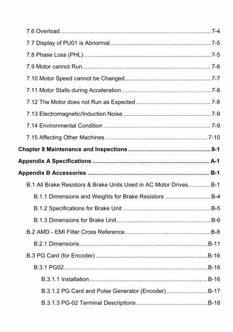
7.6 Overload............................................................................................. 7-4 7.7 Display of PU01 is Abnormal.............................................................. 7-5 7.8 Phase Loss (PHL) .............................................................................. 7-5 7.9 Motor cannot Run............................................................................... 7-6 7.10 Motor Speed cannot be Changed..................................................... 7-7 7.11 Motor Stalls during Acceleration....................................................... 7-8 7.12 The Motor does not Run as Expected .............................................. 7-8 7.13 Electromagnetic/Induction Noise ...................................................... 7-9 7.14 Environmental Condition .................................................................. 7-9 7.15 Affecting Other Machines ............................................................... 7-10
Chapter 8 Maintenance and Inspections................................................... 8-1 Appendix A Specifications ........................................................................ A-1 Appendix B Accessories ........................................................................... B-1
B.1 All Brake Resistors & Brake Units Used in AC Motor Drives..............B-1 B.1.1 Dimensions and Weights for Brake Resistors ............................B-4 B.1.2 Specifications for Brake Unit ......................................................B-5 B.1.3 Dimensions for Brake Unit ..........................................................B-6
B.2 AMD - EMI Filter Cross Reference.....................................................B-8 B.2.1 Dimensions...............................................................................B-11
B.3 PG Card (for Encoder) .....................................................................B-16 B.3.1 PG02 ........................................................................................B-16
B.3.1.1 Installation.........................................................................B-16 B.3.1.2 PG Card and Pulse Generator (Encoder) .........................B-17 B.3.1.3 PG-02 Terminal Descriptions............................................B-18
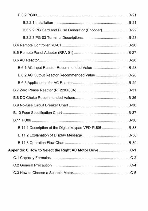
B.3.2 PG03.........................................................................................B-21
B.3.2.1 Installation .........................................................................B-21 B.3.2.2 PG Card and Pulse Generator (Encoder)..........................B-22 B.3.2.3 PG-03 Terminal Descriptions ............................................B-23
B.4 Remote Controller RC-01................................................................ B-26 B.5 Remote Panel Adapter (RPA 01) .................................................... B-27 B.6 AC Reactor...................................................................................... B-28
B.6.1 AC Input Reactor Recommended Value ...................................B-28 B.6.2 AC Output Reactor Recommended Value ................................B-28 B.6.3 Applications for AC Reactor......................................................B-29
B.7 Zero Phase Reactor (RF220X00A) ................................................. B-31 B.8 DC Choke Recommended Values................................................... B-36 B.9 No-fuse Circuit Breaker Chart ......................................................... B-36 B.10 Fuse Specification Chart ............................................................... B-37 B.11 PU06 ............................................................................................. B-38
B.11.1 Description of the Digital keypad VFD-PU06 ..........................B-38 B.11.2 Explanation of Display Message.............................................B-38 B.11.3 Operation Flow Chart..............................................................B-39
Appendix C How to Select the Right AC Motor Drive .............................. C-1 C.1 Capacity Formulas ............................................................................ C-2 C.2 General Precaution ........................................................................... C-4 C.3 How to Choose a Suitable Motor....................................................... C-5
Revision May 2009, BWE0, SW V1.05 1-1
Chapter 1 Introduction
1.1 Receiving and Inspection
This VFD-BW AC motor drive has gone through rigorous quality control tests at the factory before
shipment. After receiving the AC motor drive, please check for the following:
Check to make sure that the package includes an AC motor drive, a user manual, dust
covers and rubber bushings.
Inspect the unit to assure it was not damaged during shipment.
Make sure that the part number indicated on the nameplate corresponds with the part
number of your order.
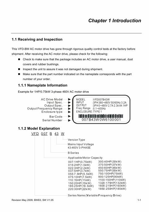
1.1.1 Nameplate Information Example for 1HP/0.75kW 3-phase 460V AC motor drive
007 B43W 0W6100 001
MODELINPUTOUT PUTFreq. Range ENCLOSURE
:VFD007B43W:3PH 380~480V 50/60Hz 3.2A:3PH 0~480V 2.7A 2.3kVA 1HP:0.1~400Hz:TYPE 1
Bar Code
AC Drive ModelInput Spec.
Output Spec .Output Frequency Range
Enclosure type
Serial Number 1.1.2 Model Explanation
危險!
VFD 0 07 B 43 W
B Series
43:460V 3-PHASE
007:1HP(0.75kW)015:2HP(1.5kW) 022:3HP(2.2kW)037:5HP(3.7kW) 055:7.5HP(5.5kW) 075:10HP(7.5kW)110:15HP(11kW) 150:20HP(15kW)185:25HP(18.5kW)220:30HP(22kW)
300:40HP(30kW) 370:50HP(37kW)450:60HP(45kW) 550:75HP(55kW) 750:100HP(75kW)900:125HP(90kW)1100:150HP(110kW)1320:175H P(132kW)1600:215H P(160kW)1850:250H P(185kW)
Vers ion TypeMains Input Voltage
Appl icable Motor Capac ity
Series Name ( ariable requency rive)V F D
Chapter 1 Introduction|VFD-BW Series
1-2 Revision May 2009, BWE0, SW V1.05
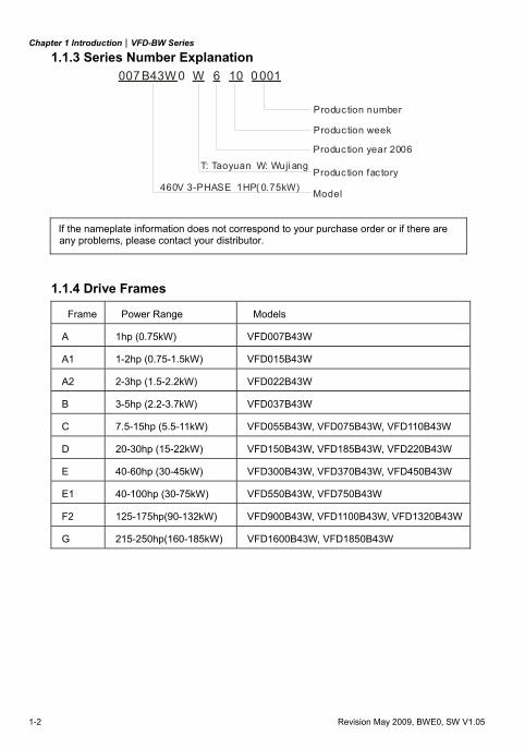
1.1.3 Series Number Explanation 007 B43W W 6 10 0 0010
460V 3-PHASE 1HP( 0.75kW)
T: Taoyuan W: Wuji ang
Produc tion number
Produc tion year 2006
Produc tion fac tory
Produc tion week
Model
If the nameplate information does not correspond to your purchase order or if there are any problems, please contact your distributor.
1.1.4 Drive Frames
Frame Power Range Models
A 1hp (0.75kW) VFD007B43W
A1 1-2hp (0.75-1.5kW) VFD015B43W
A2 2-3hp (1.5-2.2kW) VFD022B43W
B 3-5hp (2.2-3.7kW) VFD037B43W
C 7.5-15hp (5.5-11kW) VFD055B43W, VFD075B43W, VFD110B43W
D 20-30hp (15-22kW) VFD150B43W, VFD185B43W, VFD220B43W
E 40-60hp (30-45kW) VFD300B43W, VFD370B43W, VFD450B43W
E1 40-100hp (30-75kW) VFD550B43W, VFD750B43W
F2 125-175hp(90-132kW) VFD900B43W, VFD1100B43W, VFD1320B43W
G 215-250hp(160-185kW) VFD1600B43W, VFD1850B43W
Chapter 1 Introduction|VFD-BW Series
Revision May 2009, BWE0, SW V1.05 1-3
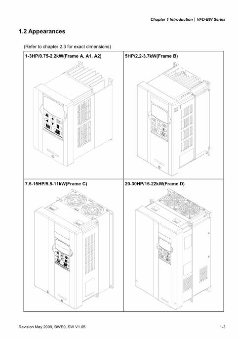
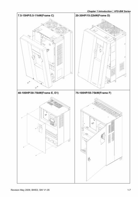
1.2 Appearances
(Refer to chapter 2.3 for exact dimensions)
1-3HP/0.75-2.2kW(Frame A, A1, A2)
5HP/2.2-3.7kW(Frame B)
7.5-15HP/5.5-11kW(Frame C)
20-30HP/15-22kW(Frame D)
Chapter 1 Introduction|VFD-BW Series
1-4 Revision May 2009, BWE0, SW V1.05
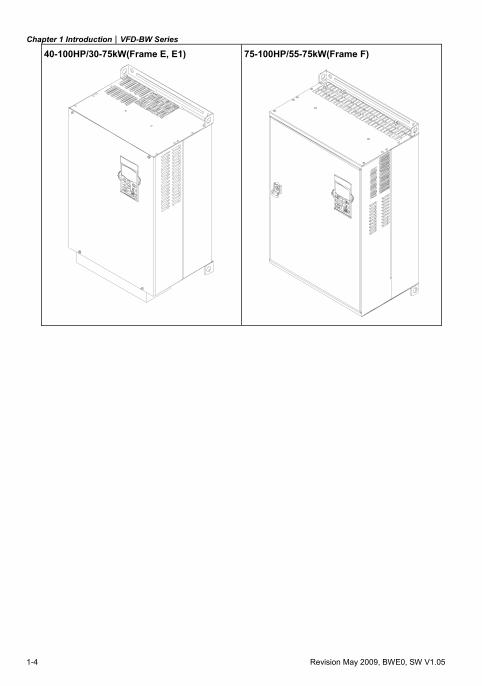
40-100HP/30-75kW(Frame E, E1)
75-100HP/55-75kW(Frame F)
Chapter 1 Introduction|VFD-BW Series
Revision May 2009, BWE0, SW V1.05 1-5
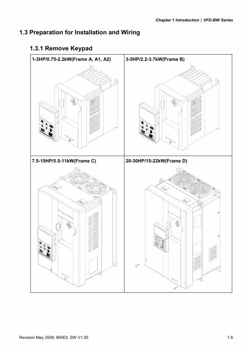
1.3 Preparation for Installation and Wiring
1.3.1 Remove Keypad 1-3HP/0.75-2.2kW(Frame A, A1, A2) 3-5HP/2.2-3.7kW(Frame B)
7.5-15HP/5.5-11kW(Frame C) 20-30HP/15-22kW(Frame D)
Chapter 1 Introduction|VFD-BW Series
1-6 Revision May 2009, BWE0, SW V1.05
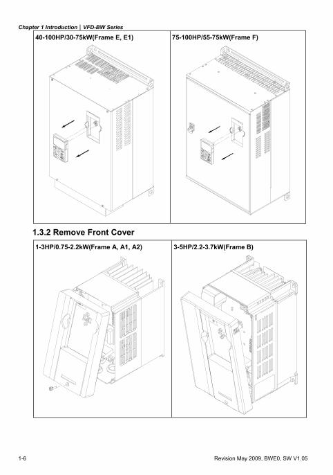
40-100HP/30-75kW(Frame E, E1)
75-100HP/55-75kW(Frame F)
1.3.2 Remove Front Cover 1-3HP/0.75-2.2kW(Frame A, A1, A2) 3-5HP/2.2-3.7kW(Frame B)
Chapter 1 Introduction|VFD-BW Series
Revision May 2009, BWE0, SW V1.05 1-7
7.5-15HP/5.5-11kW(Frame C) 20-30HP/15-22kW(Frame D)
40-100HP/30-75kW(Frame E, E1) 75-100HP/55-75kW(Frame F)
Chapter 1 Introduction|VFD-BW Series
1-8 Revision May 2009, BWE0, SW V1.05
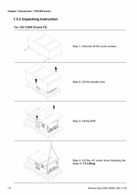
1.3.3 Unpacking Instruction
For 125-175HP (Frame F2)
Step 1: Unscrew all the cover screws.
Step 2: Lift the wooden box.
Step 3: Lift the EPE.
Step 4: Lift the AC motor drive following the steps in 1.4 Lifting.
Chapter 1 Introduction|VFD-BW Series
Revision May 2009, BWE0, SW V1.05 1-9
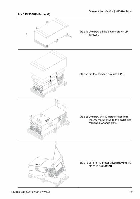
For 215-250HP (Frame G)
Step 1: Unscrew all the cover screws (24 screws).
Step 2: Lift the wooden box and EPE.
Step 3: Unscrew the 12 screws that fixed the AC motor drive to the pallet and remove 4 wooden slats.
Step 4: Lift the AC motor drive following the steps in 1.4 Lifting.
Chapter 1 Introduction|VFD-BW Series
1-10 Revision May 2009, BWE0, SW V1.05
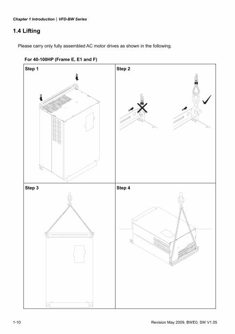
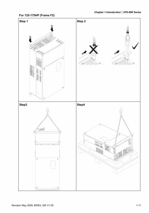
1.4 Lifting
Please carry only fully assembled AC motor drives as shown in the following.
For 40-100HP (Frame E, E1 and F)
Step 1
Step 2
Step 3
Step 4
Chapter 1 Introduction|VFD-BW Series
Revision May 2009, BWE0, SW V1.05 1-11
For 125-175HP (Frame F2)
Step 1
Step 2
Step3
Step4
Chapter 1 Introduction|VFD-BW Series
1-12 Revision May 2009, BWE0, SW V1.05
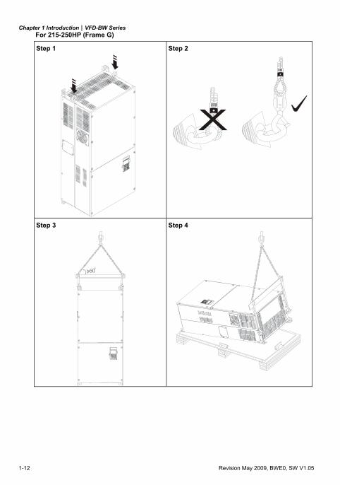
For 215-250HP (Frame G)
Step 1
Step 2
Step 3
Step 4
Chapter 1 Introduction|VFD-BW Series
Revision May 2009, BWE0, SW V1.05 1-13
1.5 Storage
The AC motor drive should be kept in the shipping carton or crate before installation. In order to retain
the warranty coverage, the AC motor drive should be stored properly when it is not to be used for an
extended period of time. Storage conditions are:
Store in a clean and dry location free from direct sunlight or corrosive fumes.
Store within an ambient temperature range of -20 °C to +60 °C.
Store within a relative humidity range of 0% to 90% and non-condensing environment.
Store within an air pressure range of 86 kPA to 106kPA.
CAUTION!
1. DO NOT store in an area with rapid changes in temperature. It may cause condensation and
frost.
2. DO NOT place on the ground directly. It should be stored properly. Moreover, if the surrounding
environment is humid, you should put exsiccator in the package.
3. If the AC motor drive is stored for more than 3 months, the temperature should not be higher
than 30 °C. Storage longer than one year is not recommended, it could result in the degradation
of the electrolytic capacitors.
4. When the AC motor drive is not used for a long time after installation on building sites or places
with humidity and dust, it’s best to move the AC motor drive to an environment as stated above.

Chapter 1 Introduction|VFD-BW Series
1-14 Revision May 2009, BWE0, SW V1.05
This page intentionally left blank.
Revision May 2009, BWE0, SW V1.05 2-1
Chapter 2 Installation and Wiring
2.1 Ambient Conditions
Install the AC motor drive in an environment with the following conditions:
Operation Air Temperature: -10 ~ +40°C (14 ~ 104°F) Relative Humidity: <90%, no condensation allowed Atmosphere pressure: 86 ~ 106 kPa Installation Site Altitude: <1000m Vibration: <20Hz: 9.80 m/s2 (1G) max
20 ~ 50Hz: 5.88 m/s2 (0.6G) max
Storage Transportation
Temperature: -20°C ~ +60°C (-4°F ~ 140°F) Relative Humidity: <90%, no condensation allowed Atmosphere pressure: 86 ~ 106 kPa Vibration: <20Hz: 9.80 m/s2 (1G) max
20 ~ 50Hz: 5.88 m/s2 (0.6G) max
Pollution Degree 2: good for a factory type environment.
CAUTION!
1. Operating, storing or transporting the AC motor drive outside these conditions may cause
damage to the AC motor drive.
2. Failure to observe these precautions may void the warranty!
2.2 Installation
1. Mount the AC motor drive vertically on a flat vertical surface by using bolts or screws. Other
directions are not allowed.
2. The AC motor drive will generate heat during operation. Allow sufficient space around the unit
for heat dissipation.
3. The heat sink temperature may rise to 90°C when running. The material on which the AC motor
drive is mounted must be noncombustible and be able to withstand this high temperature.
4. When the AC motor drive is installed in a confined space (e.g. cabinet), the surrounding
temperature must be within 10 ~ 40°C with good ventilation. DO NOT install the AC motor drive
in a space with bad ventilation.
Chapter 2 Installation and Wiring|VFD-BW Series
2-2 Revision May 2009, BWE0, SW V1.05
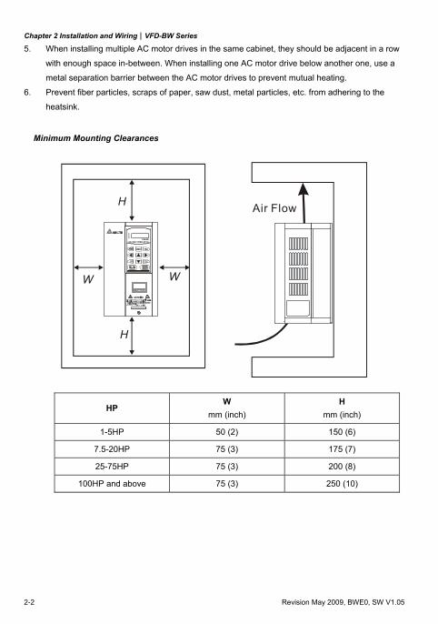
5. When installing multiple AC motor drives in the same cabinet, they should be adjacent in a row
with enough space in-between. When installing one AC motor drive below another one, use a
metal separation barrier between the AC motor drives to prevent mutual heating.
6. Prevent fiber particles, scraps of paper, saw dust, metal particles, etc. from adhering to the
heatsink.
Minimum Mounting Clearances
H
DATAPROG
REVFWD
Air Flow
H
W W
HP W
mm (inch) H
mm (inch)
1-5HP 50 (2) 150 (6)
7.5-20HP 75 (3) 175 (7)
25-75HP 75 (3) 200 (8)
100HP and above 75 (3) 250 (10)
Chapter 2 Installation and Wiring|VFD-BW Series
Revision May 2009, BWE0, SW V1.05 2-3
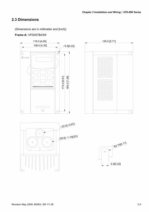
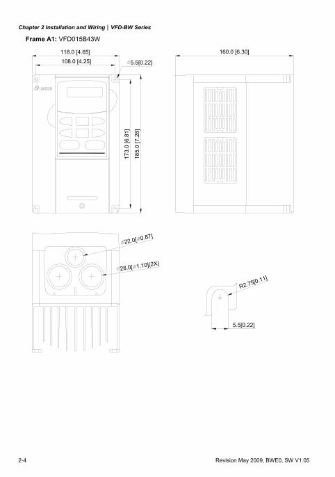
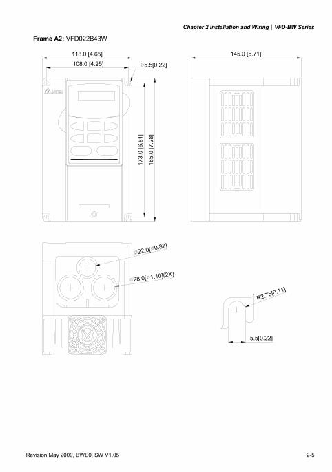
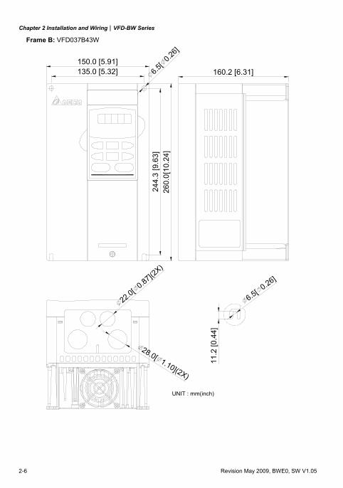
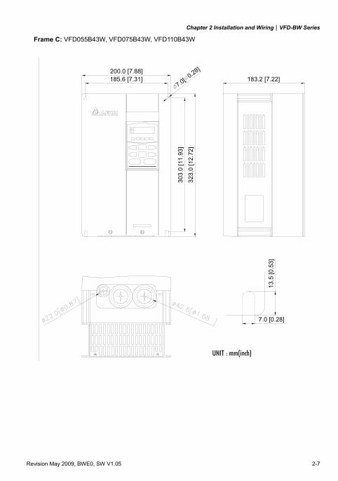
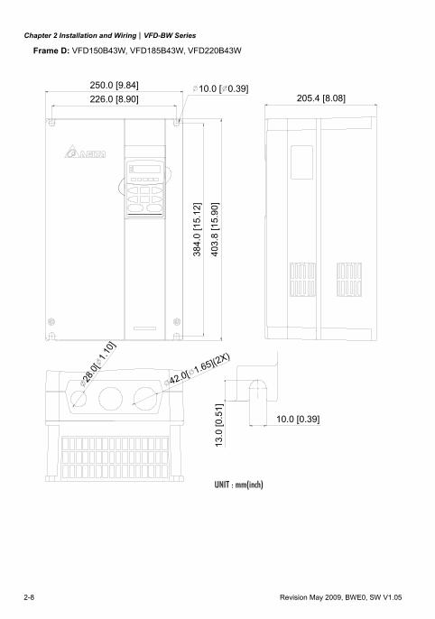
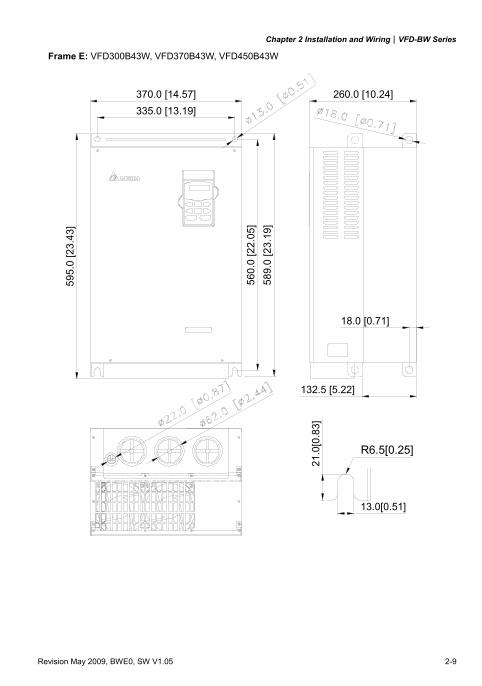
2.3 Dimensions
(Dimensions are in millimeter and [inch])
Frame A: VFD007B43W
5.5[0.22]
5.5[0.22]108.0 [4.25]118.0 [4.65]
173.
0 [6
.81]
185.
0 [7
.28]
R2.75[0.11]
145.0 [5.71]
22.0[ 0.87]
28.0[ 1.10](2X)
Chapter 2 Installation and Wiring|VFD-BW Series
2-4 Revision May 2009, BWE0, SW V1.05
Frame A1: VFD015B43W
5.5[0.22]
R2.75[0.11]
5.5[0.22]
185.
0 [7
.28]
173.
0 [6
.81]
160.0 [6.30]118.0 [4.65]108.0 [4.25]
28.0[ 1.10](2X)
22.0[ 0.87]
Chapter 2 Installation and Wiring|VFD-BW Series
Revision May 2009, BWE0, SW V1.05 2-5
Frame A2: VFD022B43W
5.5[0.22]
R2.75[0.11]
5.5[0.22]
185.
0 [7
.28]
173.
0 [6
.81]
145.0 [5.71]118.0 [4.65]108.0 [4.25]
28.0[ 1.10](2X)
22.0[ 0.87]
Chapter 2 Installation and Wiring|VFD-BW Series
2-6 Revision May 2009, BWE0, SW V1.05
Frame B: VFD037B43W
22.0[ 0.87](2X)
28.0[ 1.10](2X)
6.5[
0.26]
11.2
[0.4
4]
6.5[ 0.26]
260.
0[10
.24]
UNIT : mm(inch)
135.0 [5.32] 160.2 [6.31]
244.
3 [9
.63]
150.0 [5.91]
Chapter 2 Installation and Wiring|VFD-BW Series
Revision May 2009, BWE0, SW V1.05 2-7
Frame C: VFD055B43W, VFD075B43W, VFD110B43W
7.0 [0.28]
13.5
[0.5
3]
183.2 [7.22]7.0[ 0.28]200.0 [7.88]
323.
0 [1
2.72
]
185.6 [7.31]
303.
0 [1
1.93
]
Chapter 2 Installation and Wiring|VFD-BW Series
2-8 Revision May 2009, BWE0, SW V1.05
Frame D: VFD150B43W, VFD185B43W, VFD220B43W
403.
8 [1
5.90
]
384.
0 [1
5.12
]
13.0
[0.5
1]
10.0 [0.39]
205.4 [8.08]10.0 [ 0.39]
42.0[ 1.65](2X)
250.0 [9.84]226.0 [8.90]
28.0
[1.
10]
Chapter 2 Installation and Wiring|VFD-BW Series
Revision May 2009, BWE0, SW V1.05 2-9
Frame E: VFD300B43W, VFD370B43W, VFD450B43W
132.5 [5.22]
18.0 [0.71]21
.0[0
.83]
335.0 [13.19]370.0 [14.57] 260.0 [10.24]
589.
0 [2
3.19
]56
0.0
[22.
05]
R6.5[0.25]
13.0[0.51]
595.
0 [2
3.43
]
Chapter 2 Installation and Wiring|VFD-BW Series
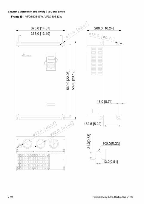
2-10 Revision May 2009, BWE0, SW V1.05
Frame E1: VFD550B43W, VFD750B43W
335.0 [13.19]370.0 [14.57] 260.0 [10.24]
589.
0 [2
3.19
]56
0.0
[22.
05]
18.0 [0.71]
132.5 [5.22]
R6.5[0.25]
13.0[0.51]
21.0
[0.8
3]
Chapter 2 Installation and Wiring|VFD-BW Series
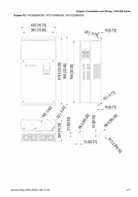
Revision May 2009, BWE0, SW V1.05 2-11
Frame F2: VFD900B43W, VFD1100B43W, VFD1320B43W
Chapter 2 Installation and Wiring|VFD-BW Series
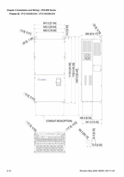
2-12 Revision May 2009, BWE0, SW V1.05
Frame G: VFD1600B43W, VFD1850B43W
Chapter 2 Installation and Wiring|VFD-BW Series
Revision May 2009, BWE0, SW V1.05 2-13
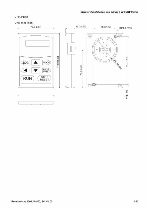
VFD-PU01
Unit: mm [inch]
6.5
[0.2
6]
19.0 [0.75]
110.
0 [4
.33]
73.0 [2.87]
97.0
[3.8
2]
44.0 [1.73]
77.0
[3.0
3]
M4* 0.7(2X)
DATAPROG
STOP
MODE
RUN
JOG
?40.0[1.58]
Chapter 2 Installation and Wiring|VFD-BW Series
2-14 Revision May 2009, BWE0, SW V1.05
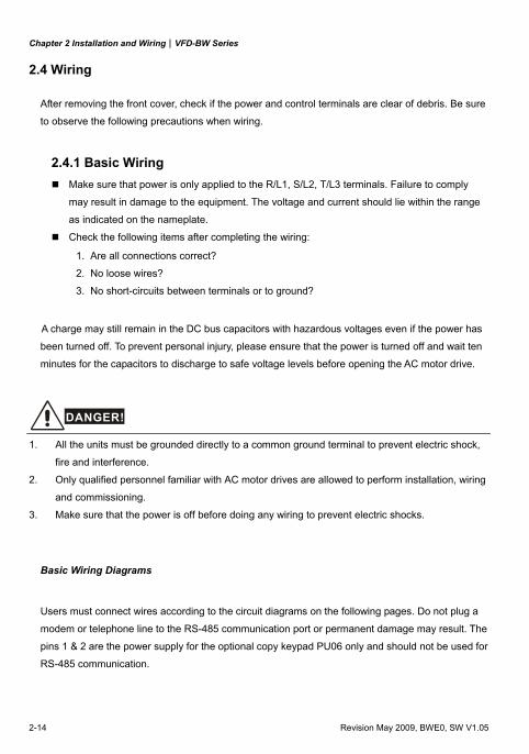
2.4 Wiring
After removing the front cover, check if the power and control terminals are clear of debris. Be sure
to observe the following precautions when wiring.
2.4.1 Basic Wiring Make sure that power is only applied to the R/L1, S/L2, T/L3 terminals. Failure to comply
may result in damage to the equipment. The voltage and current should lie within the range
as indicated on the nameplate.
Check the following items after completing the wiring:
1. Are all connections correct?
2. No loose wires?
3. No short-circuits between terminals or to ground?
A charge may still remain in the DC bus capacitors with hazardous voltages even if the power has
been turned off. To prevent personal injury, please ensure that the power is turned off and wait ten
minutes for the capacitors to discharge to safe voltage levels before opening the AC motor drive.
DANGER!
1. All the units must be grounded directly to a common ground terminal to prevent electric shock,
fire and interference.
2. Only qualified personnel familiar with AC motor drives are allowed to perform installation, wiring
and commissioning.
3. Make sure that the power is off before doing any wiring to prevent electric shocks.
Basic Wiring Diagrams
Users must connect wires according to the circuit diagrams on the following pages. Do not plug a
modem or telephone line to the RS-485 communication port or permanent damage may result. The
pins 1 & 2 are the power supply for the optional copy keypad PU06 only and should not be used for
RS-485 communication.
Chapter 2 Installation and Wiring|VFD-BW Series
Revision May 2009, BWE0, SW V1.05 2-15
R(L1)S(L2)T(L3)
SA
OFF ON
MC
MC
RB
RC
AVI
ACIAUI
ACM
+1 +2/B1 B2
MO1
MO2
MO3
Power Supply+10V 20mA
Master Frequency0~10V(47K )
4~20mA-10~+10V
+10V
5K
32
1
AFM
ACM
RA
RB
RC
MCM
DFM
DCM
RS-4856 1←
U(T1)
V(T2)
W(T3)
M3~
R(L1)S(L2)T(L3)
FWDREVJOGEFMI1
MI2MI3MI4
MI6TRG
MI5
DCM
+24VFactory Setting:Sink Mode
SW1
Sink
Source
1: EV2: GND3: SG-4: SG+5: 6:
Reserved Reserved
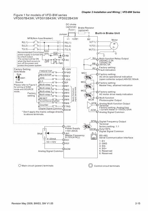
Figure 1 for models of VFD-BW seriesVFD007B43W; VFD015B43W; VFD022B43W
NFB(Non-fuse Breaker)
Jumper
DC choke(optional)
Motor
Recommended Circuit when power supply is turned OFF by a fault output.The contact will be ONwhen the fault occurs to turn off the power and protect the power system.
Please refer to Figure 5for wiring of SINKmode and SOURCEmode.
FWD/STOPREV/STOPJOGE.F.Mult i-step 1Mult i-step 2Mult i-step 3Multi-step 4
RESETAccel/Decel prohibit
CounterDigital Signal Common
* Don't apply the mains voltage directly to above terminals.
Factory sett ing:Master freq. attained indication
Factory setting:AC drive operational indication(open collector output) 48VDC 50mA
Factory sett ing:AC motor drive ready indicationMult i-function Photocoupler OutputAnalog Multi-function OutputTerminalFactory setting: Analog freq./ current meter 0~10VDC/2mAAnalog Signal Common
Digital Frequency OutputTerminalfactory setting: 1:1 Duty=50%Digital Signal Common
Serial Communication Interface
Analog Signal Common
Main circuit (power) terminals Control circuit terminals
Factorysetting
Mul
ti-fu
nctio
n in
put t
erm
inal
s
Built-in Brake Unit
Factory setting:Fault indication
Brake Resistor(optional)
Multi-function Relay Output 240VAC 2.5A 120VAC 5A 28VDC 5A
Chapter 2 Installation and Wiring|VFD-BW Series
2-16 Revision May 2009, BWE0, SW V1.05
MO1
MO2
MO3
RA
RB
RC
MCM
DFM
DCM
RS-4856 1←
+1 +2/B1 B2 -
VFDB
BR
BR
R(L1)S(L2)T(L3)
SA
OFF ON
MC
MC
RB
RC
RST
U(T1)
V(T2)
W(T3)
M3~
AFM
ACM
AVI
ACIAUI
ACM
Power Supply+10V 20mA
Master Frequency0~10V(47K )4~20mA
-10~+10V
+10V
5K
32
1
FWDREVJOGEFMI1MI2MI3MI4
MI6TRG
MI5
DCM
+24VFactory Setting:Sink Mode
SW1Sink
Source
1: EV2: GND3: SG-4: SG+5: 6:
ReservedReserved
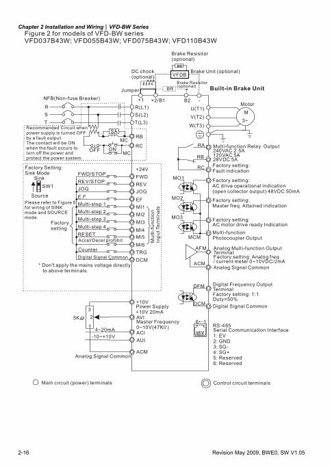
Figure 2 for models of VFD-BW seriesVFD037B43W; VFD055B43W; VFD075B43W; VFD110B43W
NFB(Non-fuse Breaker)
Recommended Circuit when power supply is turned OFF by a fault output.The contact will be ONwhen the fault occurs toturn off the power and protect the power system.
DC chock(optional)
Jumper Built-in Brake Unit
Motor
Factory setting:Fault indication
Factory sett ing:AC drive operational indication(open collector output) 48VDC 50mA
Factory sett ing:Master freq. Attained indication
Factory setting:AC motor drive ready IndicationMulti-function Photocoupler Output
Analog Mult i-function OutputTerminalFactory sett ing: Analog freq./ current meter 0~10VDC/2mAAnalog Signal Common
Digital Frequency OutputTerminalFactory sett ing: 1:1 Duty=50%Digital Signal Common
Serial Communication Interface
Analog Signal Common
Main circuit (power) terminals Control circuit terminals
Please refer to Figure 5for wiring of SINKmode and SOURCEmode.
FWD/STOPREV/STOPJOGE.F.Mult i-step 1Mult i-step 2Mult i-step 3Mult i-step 4RESETAccel/Decel prohib it
CounterDigital Signal Common
* Don't apply the mains voltage directly to above terminals.
Factorysetting
Mul
ti-fu
nctio
n In
put T
erm
inal
s
Brake Resisitor(optional)
Brake Resisitor(optional)
Brake Unit (optional)
Multi-function Relay Output 240VAC 2.5A 120VAC 5A 28VDC 5A
Chapter 2 Installation and Wiring|VFD-BW Series
Revision May 2009, BWE0, SW V1.05 2-17
FWDREVJOGEFMI1MI2MI3MI4
MI6TRG
MI5
DCM
+24V
Sink
SW1
SourceMO1
MO2
MO3
RA
RB
RC
Multi-function Relay Output 240VAC 2.5A 120VAC 5A 28VDC 5A
(open collector output) 48VDC 50mA
MCM
RS-485Serial Communication Interface
6 1←
DFM
DCM
U(T1)
V(T2)
W(T3)
M3~
+1 +2
R(L1)S(L2)T(L3)
SA
OFF ON
MC
MC
RB
RC
RST
AFM
ACM
AVI
ACIAUI
ACM
Power Supply+10V 20mA
Master Frequency0~10V(47K )4~20mA
-10~+10V
+10V
5K
32
1
1: EV2: GND3: SG-4: SG+5: 6:
ReservedReserved
VFDB
BR
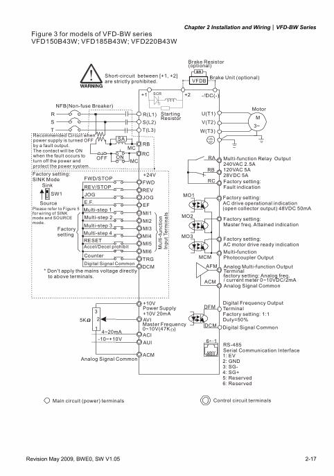
SCR
Short-circuit between [+1, +2] are strictly prohibited.
Starting Resistor
Brake Resistor(optional)
Brake Unit (optional)
MotorNFB(Non-fuse Breaker)
Recommended Circui t when power supply is turned OFF by a fault output.The contact will be ONwhen the faul t occurs toturn off the power and protect the power system.
Factory setting:Fault indication
Factory setting:AC drive operational indication
Factory setting:Master freq. Attained indication
Factory setting:AC motor drive ready indicationMulti-function Photocoupler Output
Analog Multi-function OutputTerminalfactory setting: Analog freq./ current meter 0~10VDC/2mAAnalog Signal Common
Digital Frequency OutputTerminalFactory setting: 1:1 Duty=50%Digital Signal Common
Factory setting: SINK Mode
Please refer to Figure 5for wir ing of SINKmode and SOURCEmode.
Factorysetting
FWD/STOP
REV/STOPJOGE.F.Mult i-step 1Multi-step 2Mult i-step 3Multi-step 4RESETAccel/Decel prohib it
CounterDigi tal Signal Common
* Don't apply the mains voltage directly to above terminals.
Mul
ti-fu
nctio
nIn
put T
erm
inal
s
Analog Signal Common
Main circuit (power) terminals Control circuit terminals
Figure 3 for models of VFD-BW seriesVFD150B43W; VFD185B43W; VFD220B43W
Chapter 2 Installation and Wiring|VFD-BW Series
2-18 Revision May 2009, BWE0, SW V1.05
FWDREVJOGEFMI1MI2MI3MI4
MI6TRG
MI5
DCM
+24V
SW1Sink
SourceMO1
MO2
MO3
RA
RB
RC
240VAC 2.5A
120VAC 5A 28VDC 5A
Multi-function Relay Output
(open collector output) 48VDC 50mA
Factory sett ing:AC drive operational indication
MCM
RS-485Serial Communication Interface
6 1←
DFM
DCM
U(T1)
V(T2)
W(T3)
M3~
+1/P1 +2/P2
VFDB
BR
R(L1)S(L2)T(L3)
SA
OFF ON
MC
MC
RB
RC
RST
AFM
ACM
AVI
ACIAUI
ACM
Power Supply+10V 20mA
Master Frequency0~10V(47K )4~20mA
-10~+10V
+10V
5K
32
1
1: EV2: GND3: SG-4: SG+5: 6:
ReservedReserved
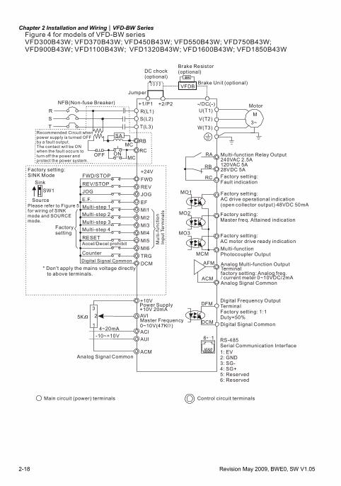
Figure 4 for models of VFD-BW seriesVFD300B43W; VFD370B43W; VFD450B43W; VFD550B43W; VFD750B43W; VFD900B43W; VFD1100B43W; VFD1320B43W; VFD1600B43W; VFD1850B43W
NFB(Non-fuse Breaker)
DC chock(optional)
Jumper
Brake Resistor(optional)
Brake Unit (optional)
Motor
Recommended Circuit when power supply is turned OFF by a fault output.The contact will be ONwhen the fault occurs toturn off the power and protect the power system.
Factory sett ing: SINK Mode
Please refer to Figure 5for wiring of SINKmode and SOURCEmode.
FWD/STOPREV/STOPJOGE.F.Mult i-step 1Multi-step 2Mult i-step 3Multi-step 4RESETAccel/Decel prohibit
CounterDigital Signal Common
* Don't apply the mains voltage directly to above terminals.
Analog Signal Common
Factory sett ing:Fault indication
Factory sett ing:Master freq. Attained indication
Factory sett ing:AC motor drive ready indicationMulti-function Photocoupler Output
Analog Mult i-function OutputTerminalfactory setting: Analog freq./ current meter 0~10VDC/2mAAnalog Signal Common
Digital Frequency OutputTerminalFactory sett ing: 1:1 Duty=50%Digital Signal Common
Main circuit (power) terminals Control circuit terminals
Mul
ti-fu
nctio
nIn
put T
erm
inal
s
Factorysetting
Chapter 2 Installation and Wiring|VFD-BW Series
Revision May 2009, BWE0, SW V1.05 2-19
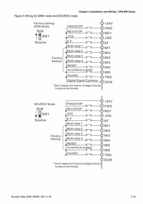
Figure 5 Wiring for SINK mode and SOURCE mode
FWDREVJOGEFMI1MI2MI3MI4
MI6TRG
MI5
DCM
+24V
SW1Sink
Source
Factory setting: SINK Mode FWD/STOP
REV/STOP
JOG
E.F.
Multi-step 1
Multi-step 2
Multi-step 3
Multi-step 4
RESETAccel/Decel prohibit
Counter
Digital Signal Common
* Don't apply the mains voltage directly to above terminals.
Factory Setting
FWDREVJOGEFMI1MI2MI3MI4
MI6TRG
MI5
DCM
+24VSOURCE Mode
SW1Sink
Source
Factory Setting
FWD/STOP
REV/STOP
JOG
E.F.
Multi-step 1
Multi-step 2
Multi-step 3
Multi-step 4
RESETAccel/Decel prohibit
Counter
* Don't apply the mains voltage directly to above terminals.
Chapter 2 Installation and Wiring|VFD-BW Series
2-20 Revision May 2009, BWE0, SW V1.05
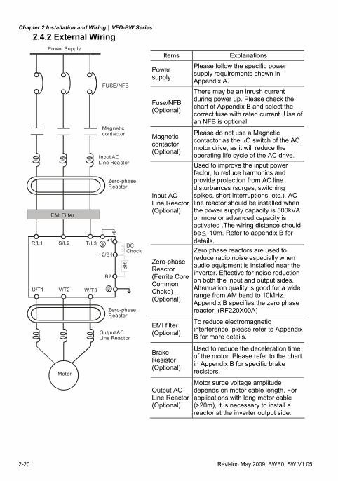
2.4.2 External Wiring
Motor
Output AC Line Reactor
Power Supply
Magneticcontactor
Input AC Line Reactor
EMI Filter
R/L1 S/L2 T/L3
U/T1 V/T2 W/T3
+2/B1
Zero-phase Reactor
Zero-phase Reactor
FUSE/NFB
B2
BR
+1DCChock
Items Explanations
Power supply
Please follow the specific power supply requirements shown in Appendix A.
Fuse/NFB (Optional)
There may be an inrush current during power up. Please check the chart of Appendix B and select the correct fuse with rated current. Use of an NFB is optional.
Magnetic contactor (Optional)
Please do not use a Magnetic contactor as the I/O switch of the AC motor drive, as it will reduce the operating life cycle of the AC drive.
Input AC Line Reactor(Optional)
Used to improve the input power factor, to reduce harmonics and provide protection from AC line disturbances (surges, switching spikes, short interruptions, etc.). AC line reactor should be installed when the power supply capacity is 500kVA or more or advanced capacity is activated .The wiring distance should be≤ 10m. Refer to appendix B for details.
Zero-phase Reactor (Ferrite Core Common Choke) (Optional)
Zero phase reactors are used to reduce radio noise especially when audio equipment is installed near the inverter. Effective for noise reduction on both the input and output sides. Attenuation quality is good for a wide range from AM band to 10MHz. Appendix B specifies the zero phase reactor. (RF220X00A)
EMI filter (Optional)
To reduce electromagnetic interference, please refer to Appendix B for more details.
Brake Resistor (Optional)
Used to reduce the deceleration time of the motor. Please refer to the chart in Appendix B for specific brake resistors.
Output AC Line Reactor(Optional)
Motor surge voltage amplitude depends on motor cable length. For applications with long motor cable (>20m), it is necessary to install a reactor at the inverter output side.
Chapter 2 Installation and Wiring|VFD-BW Series
Revision May 2009, BWE0, SW V1.05 2-21
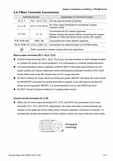
2.4.3 Main Terminals Connections Terminal Symbol Explanation of Terminal Function
R, S, T R/L1, S/L2, T/L3 AC line input terminals (3-phase)
U, V, W U/T1, V/T2, W/T3 AC drive output terminals for connecting 3-phase induction motor
P1, P2 +1, +2 Connections for DC reactor (optional). Please remove the jumper before connecting DC reactor. Models of 15kW and above have a built-in DC reactor.
P-B, P2/B1-B2 +2/B1, B2 Connections for brake resistor (optional)
P2-N, P2/B1-N [+2-(-),+2/B1-(-)] Connections for external brake unit (VFDB series)
Earth connection, please comply with local regulations.
Mains power terminals (R/L1, S/L2, T/L3)
Connect these terminals (R/L1, S/L2, T/L3) via a non-fuse breaker or earth leakage breaker
to 3-phase AC power for circuit protection. It is unnecessary to consider phase-sequence.
It is recommended to add a magnetic contactor (MC) in the power input wiring to cut off
power quickly and reduce malfunction when activating the protection function of AC motor
drives. Both ends of the MC should have an R-C surge absorber.
Do NOT run/stop AC motor drives by turning the power ON/OFF. Run/stop AC motor drives
by RUN/STOP command via control terminals or keypad. If you still need to run/stop AC
drives by turning power ON/OFF, it is recommended to do so only ONCE per hour.
Do NOT connect 3-phase models to a 1-phase power source.
Control circuit terminals (U, V, W)
When the AC drive output terminals U/T1, V/T2, and W/T3 are connected to the motor
terminals U/T1, V/T2, and W/T3, respectively, the motor will rotate counterclockwise (as
viewed on the shaft end of the motor) when a forward operation command is received. To
permanently reverse the direction of motor rotation, switch over any of the two motor leads.
Forwardrunning
Chapter 2 Installation and Wiring|VFD-BW Series
2-22 Revision May 2009, BWE0, SW V1.05
DO NOT connect phase-compensation capacitors or surge absorbers at the output terminals
of AC motor drives.
With long motor cables, high capacitive switching current peaks can cause over-current, high
leakage current or lower current readout accuracy. To prevent this, the motor cable should
be less than 20m for 3.7kW models and below. And the cable should be less than 50m for
5.5kW models and above. For longer motor cables use an AC output reactor.
Use a well-insulated motor, suitable for inverter operation.
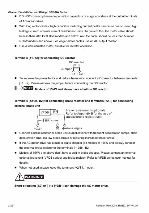
Terminals [+1, +2] for connecting DC reactor
+1
Jumper
DC reactor
To improve the power factor and reduce harmonics, connect a DC reactor between terminals
[+1, +2]. Please remove the jumper before connecting the DC reactor.
NOTE Models of 15kW and above have a built-in DC reactor.
Terminals [+2/B1, B2] for connecting brake resistor and terminals [+2, -] for connecting external brake unit
B2
VFDB
-(minus sign)
BR
BR
Connect a brake resistor or brake unit in applications with frequent deceleration ramps, short
deceleration time, too low brake torque or requiring increased brake torque.
If the AC motor drive has a built-in brake chopper (all models of 15kW and below), connect
the external brake resistor to the terminals [+2/B1, B2].
Models of 15kW and above don’t have a built-in brake chopper. Please connect an external
optional brake unit (VFDB series) and brake resistor. Refer to VFDB series user manual for
details.
When not used, please leave the terminals [+2/B1, -] open.
WARNING!
Short-circuiting [B2] or [-] to [+2/B1] can damage the AC motor drive.
Chapter 2 Installation and Wiring|VFD-BW Series
Revision May 2009, BWE0, SW V1.05 2-23
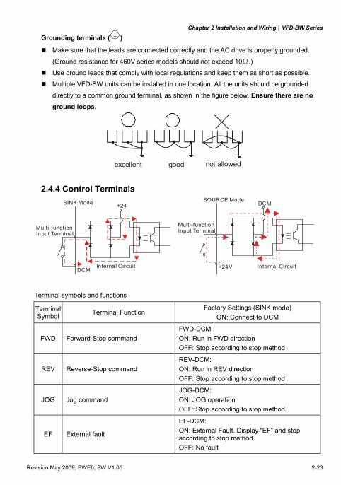
Grounding terminals ( )
Make sure that the leads are connected correctly and the AC drive is properly grounded.
(Ground resistance for 460V series models should not exceed 10Ω.)
Use ground leads that comply with local regulations and keep them as short as possible.
Multiple VFD-BW units can be installed in one location. All the units should be grounded
directly to a common ground terminal, as shown in the figure below. Ensure there are no ground loops.
goodexcellent not allowed
2.4.4 Control Terminals
+24SINK Mode
DCMInternal Circuit
Multi-functionInput Terminal
SOURCE Mode
+24V
DCM
Multi-functionInput Terminal
Internal Circuit
Terminal symbols and functions
Terminal Symbol Terminal Function
Factory Settings (SINK mode) ON: Connect to DCM
FWD Forward-Stop command FWD-DCM: ON: Run in FWD direction OFF: Stop according to stop method
REV Reverse-Stop command REV-DCM: ON: Run in REV direction OFF: Stop according to stop method
JOG Jog command JOG-DCM: ON: JOG operation OFF: Stop according to stop method
EF External fault
EF-DCM: ON: External Fault. Display “EF” and stop according to stop method. OFF: No fault
Chapter 2 Installation and Wiring|VFD-BW Series
2-24 Revision May 2009, BWE0, SW V1.05
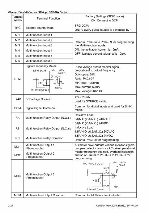
Terminal Symbol Terminal Function
Factory Settings (SINK mode) ON: Connect to DCM
TRG External counter input TRG-DCM: ON: At every pulse counter is advanced by 1.
MI1 Multi-function Input 1
MI2 Multi-function Input 2
MI3 Multi-function Input 3
MI4 Multi-function Input 4
MI5 Multi-function Input 5
MI6 Multi-function Input 6
Refer to Pr.04-04 to Pr.04-09 for programming the Multi-function Inputs. ON: the activation current is 16mA. OFF: leakage current tolerance is 10μA.
DFM
Digital Frequency Meter Max: 48V 50mA
DFM-DCM
100%
50%
Internal Circuit
Pulse voltage output monitor signal, proportional to output frequency Duty-cycle: 50% Ratio: Pr.03-07 Min. load: 10Kohm Max. current: 50mA Max. voltage: 48VDC
+24V DC Voltage Source +24V 20mA used for SOURCE mode.
DCM Digital Signal Common Common for digital inputs and used for SINK mode.
RA Multi-function Relay Output (N.O.) a
RB Multi-function Relay Output (N.C.) b
RC Multi-function Relay Common
Resistive Load: 5A(N.O.)/3A(N.C.) 240VAC 5A(N.O.)/3A(N.C.) 24VDC Inductive Load: 1.5A(N.O.)/0.5A(N.C.) 240VAC 1.5A(N.O.)/0.5A(N.C.) 24VDC Refer to Pr.03-00 for programming.
MO1 Multi-function Output 1 (Photocoupler)
MO2 Multi-function Output 2 (Photocoupler)
MO3 Multi-function Output 3 (Photocoupler)
AC motor drive outputs various monitor signals by open collector, such as AC drive operational, master frequency attained, overload indication and so on. Refer to Pr.03-01 to Pr.03-03 for programming.
MO1~MO3-DCM
MO1~
MO3
MCM
Max: 48Vdc 50mA
Internal Circuit MCM Multi-function Output Common Common for Multi-function Outputs
Chapter 2 Installation and Wiring|VFD-BW Series
Revision May 2009, BWE0, SW V1.05 2-25
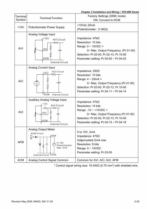
Terminal Symbol Terminal Function
Factory Settings (SINK mode) ON: Connect to DCM
+10V Potentiometer Power Supply +10Vdc 20mA (Potentiometer: 3~5KΩ)
AVI
Analog Voltage Input
ACM
AVI
+10V AVI Circuit
Internal Circuit
Impedance: 47kΩ Resolution: 10 bits Range: 0 ~ 10VDC =
0~ Max. Output Frequency (Pr.01-00) Selection: Pr.02-00, Pr.02-13, Pr.10-00 Parameter setting: Pr.04-00 ~ Pr.04-03
ACI
Analog Current Input
ACM
ACI ACI Circuit
Internal Circuit
Impedance: 250Ω Resolution: 10 bits Range: 4 ~ 20mA =
0~ Max. Output Frequency (Pr.01-00) Selection: Pr.02-00, Pr.02-13, Pr.10-00 Parameter setting: Pr.04-11 ~ Pr.04-14
AUI
Auxiliary Analog Voltage Input
ACM
AUI
+10~
-10VAUI Circuit
Internal Circuit
Impedance: 47kΩ Resolution: 10 bits Range: -10 ~ +10VDC =
0~ Max. Output Frequency (Pr.01-00) Selection: Pr.02-00, Pr.02-13, Pr.10-00 Parameter setting: Pr.04-15 ~ Pr.04-18
AFM
Analog Output Meter ACM Circuit
AFM
ACM
0~10VPotentiometerMax. 2mA
Internal Circuit
0 to 10V, 2mA Impedance: 470Ω Output current: 2mA max Resolution: 8 bits Range: 0 ~ 10VDC Parameter setting: Pr.03-05
ACM Analog Control Signal Common Common for AVI, ACI, AUI, AFM
* Control signal wiring size: 18 AWG (0.75 mm2) with shielded wire.
Chapter 2 Installation and Wiring|VFD-BW Series
2-26 Revision May 2009, BWE0, SW V1.05
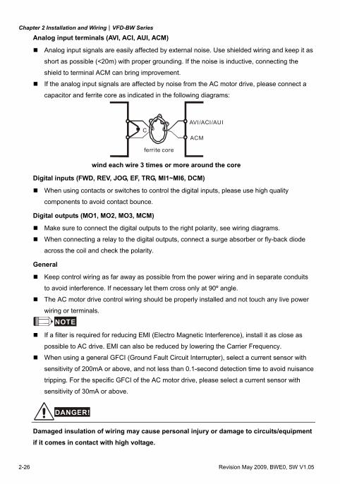
Analog input terminals (AVI, ACI, AUI, ACM)
Analog input signals are easily affected by external noise. Use shielded wiring and keep it as
short as possible (<20m) with proper grounding. If the noise is inductive, connecting the
shield to terminal ACM can bring improvement.
If the analog input signals are affected by noise from the AC motor drive, please connect a
capacitor and ferrite core as indicated in the following diagrams:
CAVI/ACI/AUI
ACM
ferrite core
wind each wire 3 times or more around the core
Digital inputs (FWD, REV, JOG, EF, TRG, MI1~MI6, DCM)
When using contacts or switches to control the digital inputs, please use high quality
components to avoid contact bounce.
Digital outputs (MO1, MO2, MO3, MCM)
Make sure to connect the digital outputs to the right polarity, see wiring diagrams.
When connecting a relay to the digital outputs, connect a surge absorber or fly-back diode
across the coil and check the polarity.
General
Keep control wiring as far away as possible from the power wiring and in separate conduits
to avoid interference. If necessary let them cross only at 90º angle.
The AC motor drive control wiring should be properly installed and not touch any live power
wiring or terminals.
NOTE If a filter is required for reducing EMI (Electro Magnetic Interference), install it as close as
possible to AC drive. EMI can also be reduced by lowering the Carrier Frequency.
When using a general GFCI (Ground Fault Circuit Interrupter), select a current sensor with
sensitivity of 200mA or above, and not less than 0.1-second detection time to avoid nuisance
tripping. For the specific GFCI of the AC motor drive, please select a current sensor with
sensitivity of 30mA or above.
DANGER!
Damaged insulation of wiring may cause personal injury or damage to circuits/equipment if it comes in contact with high voltage.
Chapter 2 Installation and Wiring|VFD-BW Series
Revision May 2009, BWE0, SW V1.05 2-27
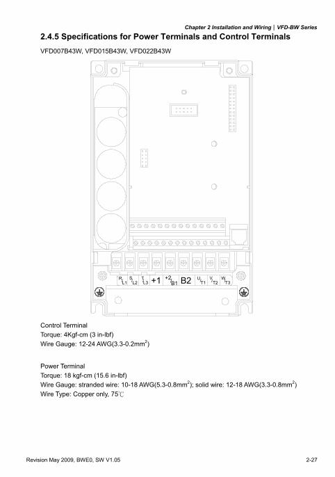
2.4.5 Specifications for Power Terminals and Control Terminals VFD007B43W, VFD015B43W, VFD022B43W
L1/ TS/ / U V W/ / /T3T2T1+2/B1
RL2 L3 +1 B2
Control Terminal Torque: 4Kgf-cm (3 in-lbf) Wire Gauge: 12-24 AWG(3.3-0.2mm2)
Power Terminal Torque: 18 kgf-cm (15.6 in-lbf) Wire Gauge: stranded wire: 10-18 AWG(5.3-0.8mm2); solid wire: 12-18 AWG(3.3-0.8mm2) Wire Type: Copper only, 75
Chapter 2 Installation and Wiring|VFD-BW Series
2-28 Revision May 2009, BWE0, SW V1.05
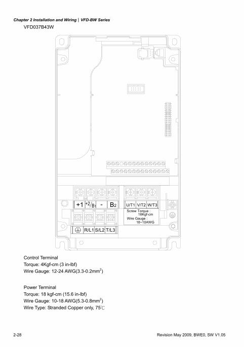
VFD037B43W
+1 +2 B1 - B2
R/L1 S/L2 T/L3
Screw Torque :
Wire Gauge : 18Kgf-cm
18~10AWG
U/T1 V/T2 W/T3
Control Terminal Torque: 4Kgf-cm (3 in-lbf) Wire Gauge: 12-24 AWG(3.3-0.2mm2)
Power Terminal Torque: 18 kgf-cm (15.6 in-lbf) Wire Gauge: 10-18 AWG(5.3-0.8mm2) Wire Type: Stranded Copper only, 75
Chapter 2 Installation and Wiring|VFD-BW Series
Revision May 2009, BWE0, SW V1.05 2-29
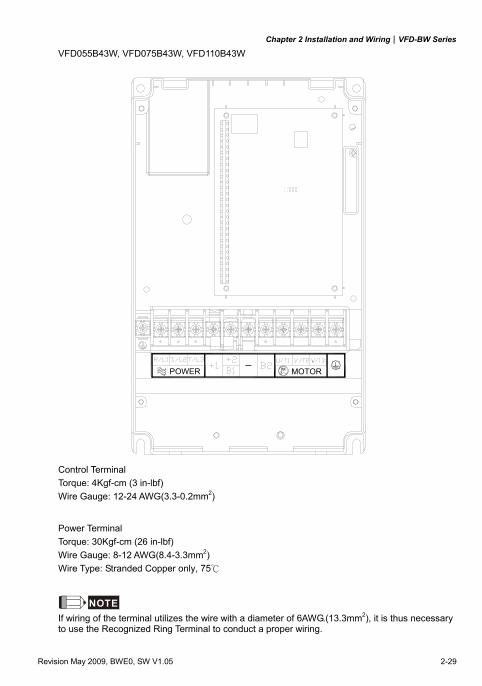
VFD055B43W, VFD075B43W, VFD110B43W
POWER IM MOTOR3
Control Terminal Torque: 4Kgf-cm (3 in-lbf) Wire Gauge: 12-24 AWG(3.3-0.2mm2)
Power Terminal Torque: 30Kgf-cm (26 in-lbf) Wire Gauge: 8-12 AWG(8.4-3.3mm2) Wire Type: Stranded Copper only, 75
NOTE If wiring of the terminal utilizes the wire with a diameter of 6AWG.(13.3mm2), it is thus necessary to use the Recognized Ring Terminal to conduct a proper wiring.
Chapter 2 Installation and Wiring|VFD-BW Series
2-30 Revision May 2009, BWE0, SW V1.05
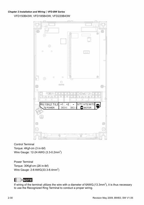
VFD150B43W, VFD185B43W, VFD220B43W
3IMPOWER
S/L2R/L1- ( ) ( ) + DC DC
T/L3 +1 -+2MOTOR
W/T3V/T2
Control Terminal Torque: 4Kgf-cm (3 in-lbf) Wire Gauge: 12-24 AWG (3.3-0.2mm2)
Power Terminal Torque: 30Kgf-cm (26 in-lbf) Wire Gauge: 2-8 AWG(33.3-8.4mm2)
NOTE If wiring of the terminal utilizes the wire with a diameter of 6AWG.(13.3mm2), it is thus necessary to use the Recognized Ring Terminal to conduct a proper wiring.
Chapter 2 Installation and Wiring|VFD-BW Series
Revision May 2009, BWE0, SW V1.05 2-31
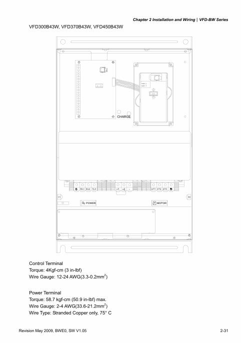
VFD300B43W, VFD370B43W, VFD450B43W
R/L1 +1 +2 -S/L2 T/L3 U/T1 V/T2 2/T3
POWER IM MOTOR3
CHARGE
POWER
ALARM
Control Terminal Torque: 4Kgf-cm (3 in-lbf) Wire Gauge: 12-24 AWG(3.3-0.2mm2)
Power Terminal Torque: 58.7 kgf-cm (50.9 in-lbf) max. Wire Gauge: 2-4 AWG(33.6-21.2mm2) Wire Type: Stranded Copper only, 75° C
Chapter 2 Installation and Wiring|VFD-BW Series
2-32 Revision May 2009, BWE0, SW V1.05
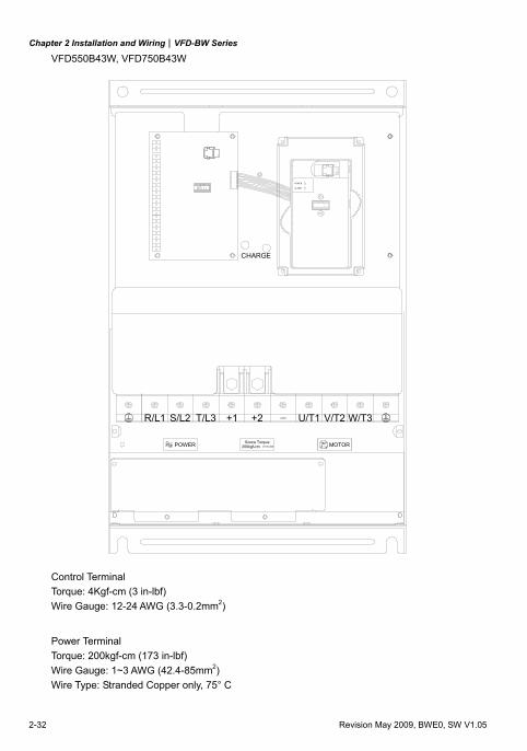
VFD550B43W, VFD750B43W
POWER
ALARM
W/T3S/L2R/L1 T/L3 +2+1 U/T1 V/T2
(173in-lbf)Screw Torque:
200kgf-cmPOWER IM MOTOR3
CHARGE
Control Terminal Torque: 4Kgf-cm (3 in-lbf) Wire Gauge: 12-24 AWG (3.3-0.2mm2)
Power Terminal Torque: 200kgf-cm (173 in-lbf) Wire Gauge: 1~3 AWG (42.4-85mm2) Wire Type: Stranded Copper only, 75° C
Chapter 2 Installation and Wiring|VFD-BW Series
Revision May 2009, BWE0, SW V1.05 2-33
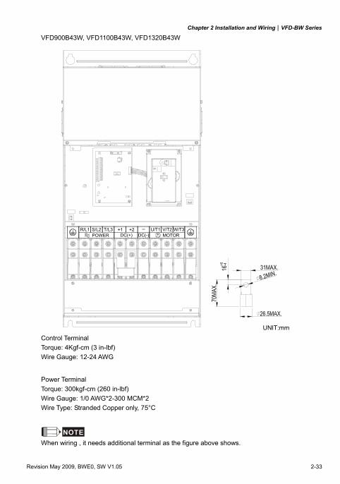
VFD900B43W, VFD1100B43W, VFD1320B43W
POWER DC(+) IM MOTORDC(-) 3
V/T2S/L2R/L1 +2T/L3 +1 U/T1 W/T3
UNIT:mm Control Terminal Torque: 4Kgf-cm (3 in-lbf) Wire Gauge: 12-24 AWG
Power Terminal Torque: 300kgf-cm (260 in-lbf) Wire Gauge: 1/0 AWG*2-300 MCM*2 Wire Type: Stranded Copper only, 75°C
NOTE When wiring , it needs additional terminal as the figure above shows.
Chapter 2 Installation and Wiring|VFD-BW Series
2-34 Revision May 2009, BWE0, SW V1.05
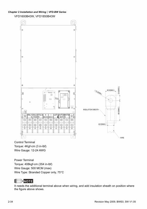
VFD1600B43W, VFD1850B43W
DC + DC ( ) ( )-POWER U/T1T/L3R/L1 S/L2 + - W/T3V/T2
Control Terminal Torque: 4Kgf-cm (3 in-lbf) Wire Gauge: 12-24 AWG
Power Terminal Torque: 408kgf-cm (354 in-lbf) Wire Gauge: 500 MCM (max) Wire Type: Stranded Copper only, 75°C
NOTE It needs the additional terminal above when wiring, and add insulation sheath on position where the figure above shows.
Revision May 2009, BWE0, SW V1.05 3-1
Chapter 3 Start Up
3.1 Preparations before Start-up
Carefully check the following items before proceeding.
Make sure that the wiring is correct. In particular, check that the output terminals U, V, W.
are NOT connected to power and that the drive is well grounded.
Verify that there are no short-circuits between terminals and from terminals to ground or
mains power.
Check for loose terminals, connectors or screws.
Verify that no other equipment is connected to the AC motor
Make sure that all switches are OFF before applying power to ensure that the AC motor
drive doesn’t start running and there is no abnormal operation after applying power.
Make sure that the front cover is correctly installed before applying power.
Do NOT operate the AC motor drive with humid hands.
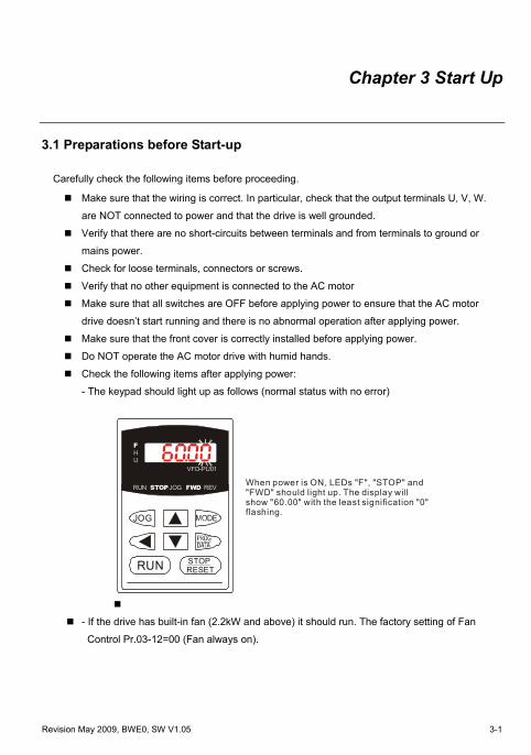
Check the following items after applying power:
- The keypad should light up as follows (normal status with no error)
U
FH
STOPRUN REV
VFD-PU01
FWDJOG
JOG
RUN RESETSTOP
When power is ON, LEDs "F", "STOP" and "FWD" should light up. The display will show "60.00" with the least signification "0" flashing.
- If the drive has built-in fan (2.2kW and above) it should run. The factory setting of Fan
Control Pr.03-12=00 (Fan always on).
Chapter 3 Start Up|VFD-BW Series
3-2 Revision May 2009, BWE0, SW V1.05
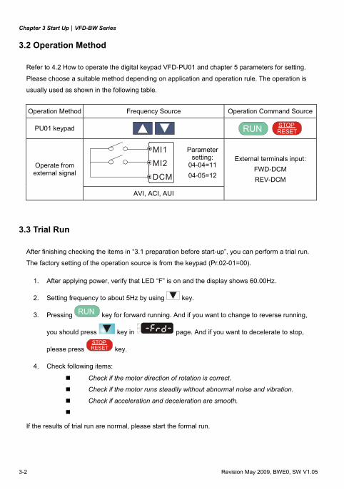
3.2 Operation Method
Refer to 4.2 How to operate the digital keypad VFD-PU01 and chapter 5 parameters for setting.
Please choose a suitable method depending on application and operation rule. The operation is
usually used as shown in the following table.
3.3 Trial Run
After finishing checking the items in “3.1 preparation before start-up”, you can perform a trial run.
The factory setting of the operation source is from the keypad (Pr.02-01=00).
1. After applying power, verify that LED “F” is on and the display shows 60.00Hz.
2. Setting frequency to about 5Hz by using key.
3. Pressing RUN key for forward running. And if you want to change to reverse running,
you should press key in U
FH
page. And if you want to decelerate to stop,
please press RESETSTOP
key.
4. Check following items: Check if the motor direction of rotation is correct.
Check if the motor runs steadily without abnormal noise and vibration.
Check if acceleration and deceleration are smooth.
If the results of trial run are normal, please start the formal run.
Operation Method Frequency Source Operation Command Source
PU01 keypad RUN RESET
STOP
MI1MI2
DCM
Parameter setting:
04-04=11 04-05=12
Operate from external signal
AVI, ACI, AUI
External terminals input: FWD-DCM REV-DCM

Chapter 3 Start Up|VFD-BW Series
Revision May 2009, BWE0, SW V1.05 3-3
NOTE
1. Stop running immediately if any fault occurs and refer to the troubleshooting guide for solving
the problem.
2. Do NOT touch output terminals U, V, W when power is still applied to L1/R, L2/S, L3/T even
when the AC motor drive has stopped. The DC-link capacitors may still be charged to
hazardous voltage levels, even if the power has been turned off.
3. To avoid damage to components, do not touch them or the circuit boards with metal objects or
your bare hands.

Chapter 3 Start Up|VFD-BW Series
3-4 Revision May 2009, BWE0, SW V1.05
This page intentionally left blank.
Revision May 2009, BWE0, SW V1.05 4-1
Chapter 4 Digital Keypad Operation
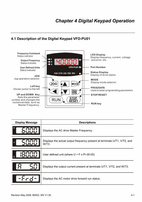
4.1 Description of the Digital Keypad VFD-PU01
U
FH
VFD-PU01
JOG
RUN RESETSTOP
LED DisplayDisplay frequency, current, voltage and error, etc.
Status DisplayDisplay of drive status
Part Number
RUN key
STOP/RESET
MODEDisplay mode selector
Left keyMoves cursor to the left
UP and DOWN KeySets the parameter
number and changes the numerical data, such as
Master Frequency.
JOGJog operation selector
Display Message Descriptions
Displays the AC drive Master Frequency.
Displays the actual output frequency present at terminals U/T1, V/T2, and W/T3.
User defined unit (where U = F x Pr.00-05)
Displays the output current present at terminals U/T1, V/T2, and W/T3.
Displays the AC motor drive forward run status.
Chapter 4 Digital Keypad Operation|VFD-BW Series
4-2 Revision May 2009, BWE0, SW V1.05
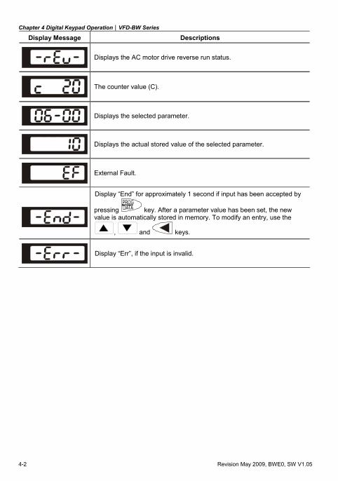
Display Message Descriptions
Displays the AC motor drive reverse run status.
The counter value (C).
Displays the selected parameter.
Displays the actual stored value of the selected parameter.
External Fault.
Display “End” for approximately 1 second if input has been accepted by
pressing key. After a parameter value has been set, the new value is automatically stored in memory. To modify an entry, use the
, and keys.
Display “Err”, if the input is invalid.
Chapter 4 Digital Keypad Operation|VFD-BW Series
Revision May 2009, BWE0, SW V1.05 4-3
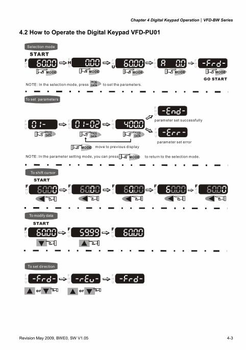
4.2 How to Operate the Digital Keypad VFD-PU01
MODE
MODE
MODEMODEMODEMODE
START
U
FH
Selection mode
START
To shift cursor
To modify data
To set direction
or
To set parameters
U
FH
UFH
U
FH
GO START
U
FH
U
FH
U
FH
U
FH
U
FH
U
FH
to set the parameters. NOTE: In the selection mode, press
to return to the selection mode.NOTE: In the parameter setting mode, you can press
move to previous display
U
FH
U
FH
U
FH
U
FH
U
FH
START
U
FH
U
FH
U
FH
U
FH
or
U
FH
U
FH
parameter set successfully
parameter set error
MODE

Chapter 4 Digital Keypad Operation|VFD-BW Series
4-4 Revision May 2009, BWE0, SW V1.05
This page intentionally left blank.
Revision May 2009, BWE0, SW V1.05 5-1
Chapter 5 Parameters
The VFD-BW parameters are divided into 12 groups by property for easy setting. In most applications,
the user can finish all parameter settings before start-up without the need for re-adjustment during
operation.
The 12 groups are as follows:
Group 00: User Parameters
Group 01: Basic Parameters
Group 02: Operation Method Parameters
Group 03: Output Function Parameters
Group 04: Input Function Parameters
Group 05: Multi-Step Speed and PLC Parameters
Group 06: Protection Parameters
Group 07: Motor Parameters
Group 08: Special Parameters
Group 09: Communication Parameters
Group 10: PID Control Parameters
Group 11: Fan & Pump Control Parameters
Chapter 5 Parameters|VFD-BW Series
5-2 Revision May 2009, BWE0, SW V1.05
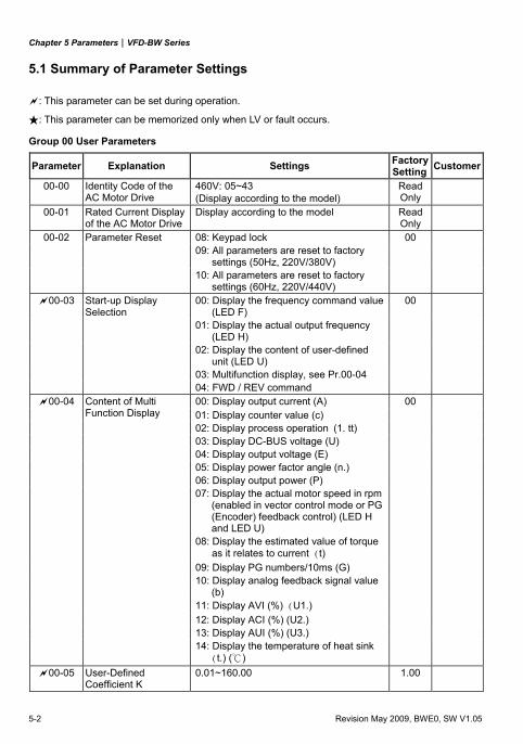
5.1 Summary of Parameter Settings
: This parameter can be set during operation.
: This parameter can be memorized only when LV or fault occurs.
Group 00 User Parameters
Parameter Explanation Settings Factory Setting Customer
00-00 Identity Code of the AC Motor Drive
460V: 05~43 (Display according to the model)
Read Only
00-01 Rated Current Display of the AC Motor Drive
Display according to the model Read Only
00-02 Parameter Reset 08: Keypad lock 00 09: All parameters are reset to factory
settings (50Hz, 220V/380V)
10: All parameters are reset to factory settings (60Hz, 220V/440V)
00-03 Start-up Display Selection
00: Display the frequency command value (LED F)
00
01: Display the actual output frequency (LED H)
02: Display the content of user-defined unit (LED U)
03: Multifunction display, see Pr.00-04 04: FWD / REV command
00: Display output current (A) 00 00-04 Content of Multi Function Display 01: Display counter value (c)
02: Display process operation (1. tt) 03: Display DC-BUS voltage (U) 04: Display output voltage (E) 05: Display power factor angle (n.) 06: Display output power (P) 07: Display the actual motor speed in rpm
(enabled in vector control mode or PG (Encoder) feedback control) (LED H and LED U)
08: Display the estimated value of torque as it relates to current (t)
09: Display PG numbers/10ms (G) 10: Display analog feedback signal value
(b)
11: Display AVI (%) (U1.) 12: Display ACI (%) (U2.) 13: Display AUI (%) (U3.) 14: Display the temperature of heat sink
(t.) ()
00-05 User-Defined Coefficient K
0.01~160.00 1.00
Chapter 5 Parameters|VFD-BW Series
Revision May 2009, BWE0, SW V1.05 5-3
Parameter Explanation Settings Factory Setting Customer
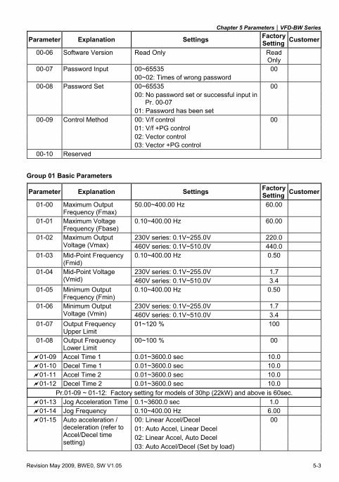
00-06 Software Version Read Only Read Only
00-07 Password Input 00~65535 00 00~02: Times of wrong password
00-08 Password Set 00~65535 00 00: No password set or successful input in
Pr. 00-07
01: Password has been set 00-09 Control Method 00: V/f control 00
01: V/f +PG control 02: Vector control 03: Vector +PG control
00-10 Reserved
Group 01 Basic Parameters
Parameter Explanation Settings Factory Setting Customer
01-00 Maximum Output Frequency (Fmax)
50.00~400.00 Hz 60.00
01-01 Maximum Voltage Frequency (Fbase)
0.10~400.00 Hz 60.00
230V series: 0.1V~255.0V 220.0 01-02 Maximum Output Voltage (Vmax) 460V series: 0.1V~510.0V 440.0
01-03 Mid-Point Frequency (Fmid)
0.10~400.00 Hz 0.50
230V series: 0.1V~255.0V 1.7 01-04 Mid-Point Voltage (Vmid) 460V series: 0.1V~510.0V 3.4
01-05 Minimum Output Frequency (Fmin)
0.10~400.00 Hz 0.50
230V series: 0.1V~255.0V 1.7 01-06 Minimum Output Voltage (Vmin) 460V series: 0.1V~510.0V 3.4
01-07 Output Frequency Upper Limit
01~120 % 100
01-08 Output Frequency Lower Limit
00~100 % 00
01-09 Accel Time 1 0.01~3600.0 sec 10.0 01-10 Decel Time 1 0.01~3600.0 sec 10.0 01-11 Accel Time 2 0.01~3600.0 sec 10.0 01-12 Decel Time 2 0.01~3600.0 sec 10.0
Pr.01-09 ~ 01-12: Factory setting for models of 30hp (22kW) and above is 60sec. 01-13 Jog Acceleration Time 0.1~3600.0 sec 1.0 01-14 Jog Frequency 0.10~400.00 Hz 6.00
00: Linear Accel/Decel 00 01: Auto Accel, Linear Decel 02: Linear Accel, Auto Decel
01-15 Auto acceleration / deceleration (refer to Accel/Decel time setting) 03: Auto Accel/Decel (Set by load)
Chapter 5 Parameters|VFD-BW Series
5-4 Revision May 2009, BWE0, SW V1.05
Parameter Explanation Settings Factory Setting Customer
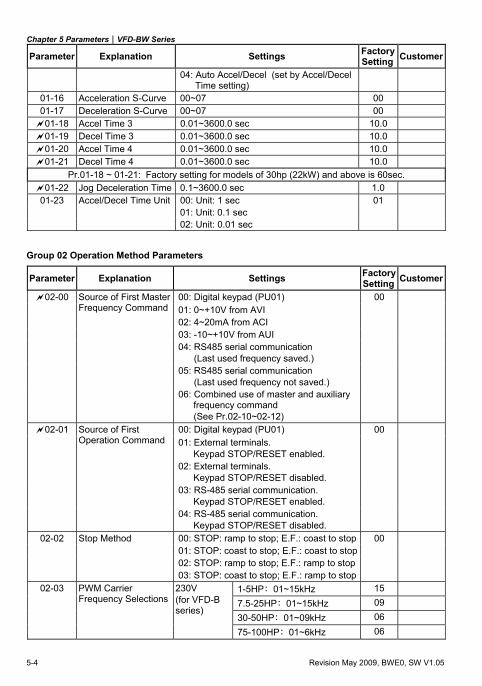
04: Auto Accel/Decel (set by Accel/Decel Time setting)
01-16 Acceleration S-Curve 00~07 00 01-17 Deceleration S-Curve 00~07 00 01-18 Accel Time 3 0.01~3600.0 sec 10.0 01-19 Decel Time 3 0.01~3600.0 sec 10.0 01-20 Accel Time 4 0.01~3600.0 sec 10.0 01-21 Decel Time 4 0.01~3600.0 sec 10.0
Pr.01-18 ~ 01-21: Factory setting for models of 30hp (22kW) and above is 60sec. 01-22 Jog Deceleration Time 0.1~3600.0 sec 1.0
01-23 Accel/Decel Time Unit 00: Unit: 1 sec 01 01: Unit: 0.1 sec 02: Unit: 0.01 sec
Group 02 Operation Method Parameters
Parameter Explanation Settings Factory Setting Customer
00: Digital keypad (PU01) 00 02-00 Source of First Master Frequency Command 01: 0~+10V from AVI
02: 4~20mA from ACI 03: -10~+10V from AUI 04: RS485 serial communication
(Last used frequency saved.)
05: RS485 serial communication (Last used frequency not saved.)
06: Combined use of master and auxiliary frequency command
(See Pr.02-10~02-12)
00: Digital keypad (PU01) 00 02-01 Source of First Operation Command 01: External terminals.
Keypad STOP/RESET enabled.
02: External terminals. Keypad STOP/RESET disabled.
03: RS-485 serial communication. Keypad STOP/RESET enabled.
04: RS-485 serial communication. Keypad STOP/RESET disabled.
02-02 Stop Method 00: STOP: ramp to stop; E.F.: coast to stop 00 01: STOP: coast to stop; E.F.: coast to stop 02: STOP: ramp to stop; E.F.: ramp to stop 03: STOP: coast to stop; E.F.: ramp to stop
1-5HP:01~15kHz 15 7.5-25HP:01~15kHz 09
02-03 PWM Carrier Frequency Selections
230V (for VFD-B series)
30-50HP:01~09kHz 06 75-100HP:01~6kHz 06
Chapter 5 Parameters|VFD-BW Series
Revision May 2009, BWE0, SW V1.05 5-5
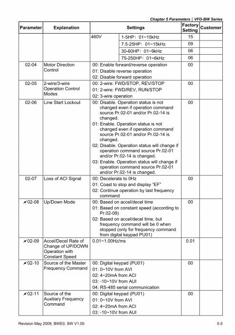
Parameter Explanation Settings Factory Setting Customer
460V 1-5HP:01~15kHz 15 7.5-25HP:01~15kHz 09 30-60HP:01~9kHz 06 75-250HP:01~6kHz 06
00: Enable forward/reverse operation 00 02-04 Motor Direction Control 01: Disable reverse operation
02: Disable forward operation 00: 2-wire: FWD/STOP, REV/STOP 00 01: 2-wire: FWD/REV, RUN/STOP
02-05 2-wire/3-wire Operation Control Modes 02: 3-wire operation
02-06 Line Start Lockout 00: Disable. Operation status is not changed even if operation command source Pr.02-01 and/or Pr.02-14 is changed.
00
01: Enable. Operation status is not changed even if operation command source Pr.02-01 and/or Pr.02-14 is changed.
02: Disable. Operation status will change if operation command source Pr.02-01 and/or Pr.02-14 is changed.
03: Enable. Operation status will change if operation command source Pr.02-01 and/or Pr.02-14 is changed.
02-07 Loss of ACI Signal 00: Decelerate to 0Hz 00 01: Coast to stop and display “EF” 02: Continue operation by last frequency
command
02-08 Up/Down Mode 00: Based on accel/decel time 00 01: Based on constant speed (according to
Pr.02-09)
02: Based on accel/decel time, but frequency command will be 0 when stopped (only for frequency command from digital keypad PU01)
02-09 Accel/Decel Rate of Change of UP/DOWN Operation with Constant Speed
0.01~1.00Hz/ms 0.01
00: Digital keypad (PU01) 00 02-10 Source of the Master Frequency Command 01: 0~10V from AVI
02: 4~20mA from ACI 03: -10~10V from AUI 04: RS-485 serial communication
00: Digital keypad (PU01) 00
01: 0~10V from AVI 02-11 Source of the
Auxiliary Frequency Command 02: 4~20mA from ACI
03: -10~10V from AUI
Chapter 5 Parameters|VFD-BW Series
5-6 Revision May 2009, BWE0, SW V1.05
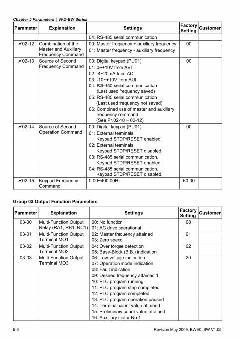
Parameter Explanation Settings Factory Setting Customer
04: RS-485 serial communication
00: Master frequency + auxiliary frequency 00 02-12 Combination of the Master and Auxiliary Frequency Command
01: Master frequency - auxiliary frequency
00: Digital keypad (PU01) 00 02-13 Source of Second Frequency Command 01: 0~+10V from AVI
02: 4~20mA from ACI 03: -10~+10V from AUI 04: RS-485 serial communication
(Last used frequency saved)
05: RS-485 serial communication (Last used frequency not saved)
06: Combined use of master and auxiliary frequency command (See Pr.02-10 ~ 02-12)
00: Digital keypad (PU01) 00 02-14 Source of Second Operation Command 01: External terminals.
Keypad STOP/RESET enabled.
02: External terminals. Keypad STOP/RESET disabled.
03: RS-485 serial communication. Keypad STOP/RESET enabled.
04: RS-485 serial communication. Keypad STOP/RESET disabled.
02-15 Keypad Frequency Command
0.00~400.00Hz 60.00
Group 03 Output Function Parameters
Parameter Explanation Settings Factory Setting Customer
03-00 Multi-Function Output Relay (RA1, RB1, RC1)
00: No function 01: AC drive operational
08
03-01 Multi-Function Output Terminal MO1
02: Master frequency attained 03: Zero speed
01
03-02 Multi-Function Output Terminal MO2
04: Over torque detection 05: Base-Block (B.B.) indication
02
03-03 Multi-Function Output Terminal MO3
06: Low-voltage indication 07: Operation mode indication
20
08: Fault indication 09: Desired frequency attained 1 10: PLC program running 11: PLC program step completed 12: PLC program completed 13: PLC program operation paused 14: Terminal count value attained 15: Preliminary count value attained 16: Auxiliary motor No.1
Chapter 5 Parameters|VFD-BW Series
Revision May 2009, BWE0, SW V1.05 5-7
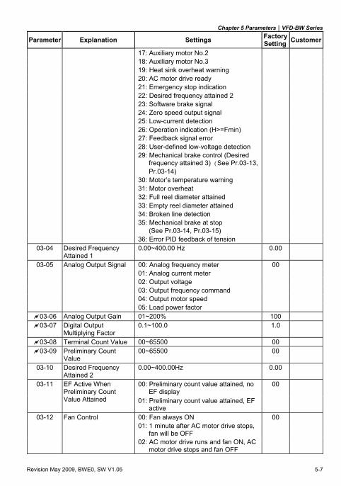
Parameter Explanation Settings Factory Setting Customer
17: Auxiliary motor No.2 18: Auxiliary motor No.3 19: Heat sink overheat warning 20: AC motor drive ready 21: Emergency stop indication 22: Desired frequency attained 2 23: Software brake signal 24: Zero speed output signal 25: Low-current detection 26: Operation indication (H>=Fmin) 27: Feedback signal error 28: User-defined low-voltage detection 29: Mechanical brake control (Desired
frequency attained 3) (See Pr.03-13, Pr.03-14)
30: Motor’s temperature warning 31: Motor overheat 32: Full reel diameter attained 33: Empty reel diameter attained 34: Broken line detection 35: Mechanical brake at stop
(See Pr.03-14, Pr.03-15)
36: Error PID feedback of tension 03-04 Desired Frequency
Attained 1 0.00~400.00 Hz 0.00
03-05 Analog Output Signal 00: Analog frequency meter 00 01: Analog current meter 02: Output voltage 03: Output frequency command 04: Output motor speed 05: Load power factor
03-06 Analog Output Gain 01~200% 100
03-07 Digital Output Multiplying Factor
0.1~100.0 1.0
03-08 Terminal Count Value 00~65500 00
03-09 Preliminary Count Value
00~65500 00
03-10 Desired Frequency Attained 2
0.00~400.00Hz 0.00
00: Preliminary count value attained, no EF display
00 03-11 EF Active When Preliminary Count Value Attained 01: Preliminary count value attained, EF
active
03-12 Fan Control 00: Fan always ON 00 01: 1 minute after AC motor drive stops,
fan will be OFF
02: AC motor drive runs and fan ON, AC motor drive stops and fan OFF
Chapter 5 Parameters|VFD-BW Series
5-8 Revision May 2009, BWE0, SW V1.05
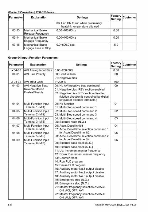
Parameter Explanation Settings Factory Setting Customer
03: Fan ON to run when preliminary heatsink temperature attained
03-13 Mechanical Brake Release Frequency
0.00~400.00Hz 0.00
03-14 Mechanical Brake Engage Frequency
0.00~400.00Hz 0.00
03-15 Mechanical Brake Engage Time at Stop
0.0~600.0 sec 5.0
Group 04 Input Function Parameters
Parameter Explanation Settings Factory Setting Customer
04-00 AVI Analog Input Bias 0.00~200.00% 0.00 00: Positive bias 00 04-01 AVI Bias Polarity 01: Negative bias
04-02 AVI Input Gain 1~200 % 100 00: No AVI negative bias command 00 01: Negative bias: REV motion enabled
04-03 AVI Negative Bias, Reverse Motion Enable/Disable 02: Negative bias: REV motion disabled
(Motion direction is controlled by digital keypad or external terminals.)
04-04 Multi-Function Input Terminal 1 (MI1)
00: No function 01: Multi-Step speed command 1
01
04-05 Multi-Function Input Terminal 2 (MI2)
02: Multi-Step speed command 2 03: Multi-Step speed command 3
02
04-06 Multi-Function Input Terminal 3 (MI3)
04: Multi-Step speed command 4 05: External reset (N.O.)
03
04-07 Multi-Function Input Terminal 4 (MI4)
04
04-08 Multi-Function Input Terminal 5 (MI5)
05
04-09 Multi-Function Input Terminal 6 (MI6)
06: Accel/Decel inhibit 07: Accel/Decel time selection command 1
for Accel/Decel time 1/2 08: Accel/Decel time selection command 2
for Accel/Decel time 3/4 09: External base block (N.O.)
06
10: External base block (N.C.) 11: Up: Increment master frequency 12: Down: Decrement master frequency 13: Counter reset 14: Run PLC program 15: Pause PLC program 16: Auxiliary motor No.1 output disable 17: Auxiliary motor No.2 output disable 18: Auxiliary motor No.3 output disable 19: Emergency stop (N.O.) 20: Emergency stop (N.C.) 21: Master frequency selection AVI/ACI
ON: ACI; OFF: AVI
22: Master frequency selection AVI/AUI ON: AUI; OFF: AVI
Chapter 5 Parameters|VFD-BW Series
Revision May 2009, BWE0, SW V1.05 5-9
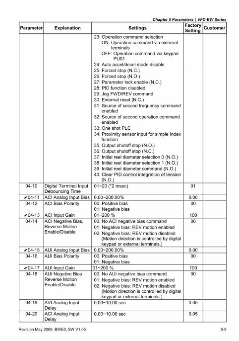
Parameter Explanation Settings Factory Setting Customer
23: Operation command selection ON: Operation command via external
terminals OFF: Operation command via keypad
PU01
24: Auto accel/decel mode disable 25: Forced stop (N.C.) 26: Forced stop (N.O.) 27: Parameter lock enable (N.C.) 28: PID function disabled 29: Jog FWD/REV command 30: External reset (N.C.) 31: Source of second frequency command
enabled
32: Source of second operation command enabled
33: One shot PLC 34: Proximity sensor input for simple Index
function
35: Output shutoff stop (N.O.) 36: Output shutoff stop (N.C.) 37: Initial reel diameter selection 0 (N.O.) 38: Initial reel diameter selection 1 (N.O.) 39: Initial reel diameter command (N.O.) 40: Clear PID control integration of tension
(N.O.)
04-10 Digital Terminal Input Debouncing Time
01~20 (*2 msec) 01
04-11 ACI Analog Input Bias 0.00~200.00% 0.00 04-12 ACI Bias Polarity 00: Positive bias 00
01: Negative bias 04-13 ACI Input Gain 01~200 % 100
00: No ACI negative bias command 00 01: Negative bias: REV motion enabled
04-14 ACI Negative Bias, Reverse Motion Enable/Disable 02: Negative bias: REV motion disabled
(Motion direction is controlled by digital keypad or external terminals.)
04-15 AUI Analog Input Bias 0.00~200.00% 0.00 04-16 AUI Bias Polarity 00: Positive bias 00
01: Negative bias 04-17 AUI Input Gain 01~200 % 100
00: No AUI negative bias command 00 01: Negative bias: REV motion enabled
04-18 AUI Negative Bias Reverse Motion Enable/Disable 02: Negative bias: REV motion disabled
(Motion direction is controlled by digital keypad or external terminals.)
04-19 AVI Analog Input Delay
0.00~10.00 sec 0.05
04-20 ACI Analog Input Delay
0.00~10.00 sec 0.05
Chapter 5 Parameters|VFD-BW Series
5-10 Revision May 2009, BWE0, SW V1.05
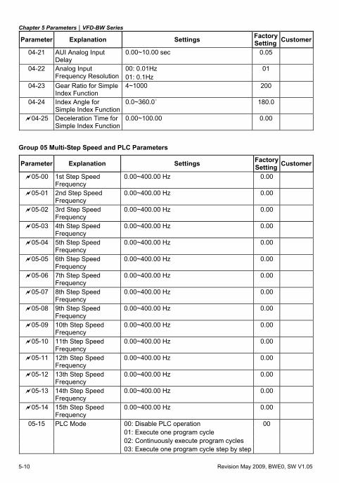
Parameter Explanation Settings Factory Setting Customer
04-21 AUI Analog Input Delay
0.00~10.00 sec 0.05
00: 0.01Hz 04-22 Analog Input Frequency Resolution 01: 0.1Hz
01
04-23 Gear Ratio for Simple Index Function
4~1000 200
04-24 Index Angle for Simple Index Function
0.0~360.0∘ 180.0
04-25 Deceleration Time for Simple Index Function
0.00~100.00 0.00
Group 05 Multi-Step Speed and PLC Parameters
Parameter Explanation Settings Factory Setting Customer
05-00 1st Step Speed Frequency
0.00~400.00 Hz 0.00
05-01 2nd Step Speed Frequency
0.00~400.00 Hz 0.00
05-02 3rd Step Speed Frequency
0.00~400.00 Hz 0.00
05-03 4th Step Speed Frequency
0.00~400.00 Hz 0.00
05-04 5th Step Speed Frequency
0.00~400.00 Hz 0.00
05-05 6th Step Speed Frequency
0.00~400.00 Hz 0.00
05-06 7th Step Speed Frequency
0.00~400.00 Hz 0.00
05-07 8th Step Speed Frequency
0.00~400.00 Hz 0.00
05-08 9th Step Speed Frequency
0.00~400.00 Hz 0.00
05-09 10th Step Speed Frequency
0.00~400.00 Hz 0.00
05-10 11th Step Speed Frequency
0.00~400.00 Hz 0.00
05-11 12th Step Speed Frequency
0.00~400.00 Hz 0.00
05-12 13th Step Speed Frequency
0.00~400.00 Hz 0.00
05-13 14th Step Speed Frequency
0.00~400.00 Hz 0.00
05-14 15th Step Speed Frequency
0.00~400.00 Hz 0.00
05-15 PLC Mode 00: Disable PLC operation 00 01: Execute one program cycle 02: Continuously execute program cycles 03: Execute one program cycle step by step
Chapter 5 Parameters|VFD-BW Series
Revision May 2009, BWE0, SW V1.05 5-11
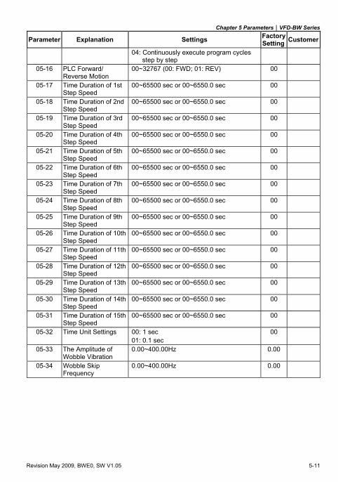
Parameter Explanation Settings Factory Setting Customer
04: Continuously execute program cycles step by step
05-16 PLC Forward/ Reverse Motion
00~32767 (00: FWD; 01: REV) 00
05-17 Time Duration of 1st Step Speed
00~65500 sec or 00~6550.0 sec 00
05-18 Time Duration of 2nd Step Speed
00~65500 sec or 00~6550.0 sec 00
05-19 Time Duration of 3rd Step Speed
00~65500 sec or 00~6550.0 sec 00
05-20 Time Duration of 4th Step Speed
00~65500 sec or 00~6550.0 sec 00
05-21 Time Duration of 5th Step Speed
00~65500 sec or 00~6550.0 sec 00
05-22 Time Duration of 6th Step Speed
00~65500 sec or 00~6550.0 sec 00
05-23 Time Duration of 7th Step Speed
00~65500 sec or 00~6550.0 sec 00
05-24 Time Duration of 8th Step Speed
00~65500 sec or 00~6550.0 sec 00
05-25 Time Duration of 9th Step Speed
00~65500 sec or 00~6550.0 sec 00
05-26 Time Duration of 10th Step Speed
00~65500 sec or 00~6550.0 sec 00
05-27 Time Duration of 11th Step Speed
00~65500 sec or 00~6550.0 sec 00
05-28 Time Duration of 12th Step Speed
00~65500 sec or 00~6550.0 sec 00
05-29 Time Duration of 13th Step Speed
00~65500 sec or 00~6550.0 sec 00
05-30 Time Duration of 14th Step Speed
00~65500 sec or 00~6550.0 sec 00
05-31 Time Duration of 15th Step Speed
00~65500 sec or 00~6550.0 sec 00
05-32 Time Unit Settings 00: 1 sec 00 01: 0.1 sec
05-33 The Amplitude of Wobble Vibration
0.00~400.00Hz 0.00
05-34 Wobble Skip Frequency
0.00~400.00Hz 0.00
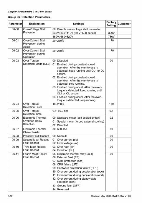
Chapter 5 Parameters|VFD-BW Series
5-12 Revision May 2009, BWE0, SW V1.05
Group 06 Protection Parameters
Parameter Explanation Settings Factory Setting Customer
00: Disable over-voltage stall prevention 06-00 Over-Voltage Stall Prevention 230V: 330~410V (for VFD-B series) 390V
460V: 660~820V 780V 06-01 Over-Current Stall
Prevention during Accel
20~250% 170
06-02 Over-Current Stall Prevention during Operation
20~250% 170
00: Disabled 00 06-03 Over-Torque Detection Mode (OL2) 01: Enabled during constant speed
operation. After the over-torque is detected, keep running until OL1 or OL occurs.
02: Enabled during constant speed operation. After the over-torque is detected, stop running.
03: Enabled during accel. After the over-torque is detected, keep running until OL1 or OL occurs.
04: Enabled during accel. After the over-torque is detected, stop running.
06-04 Over-Torque Detection Level
10~200% 150
06-05 Over-Torque Detection Time
0.1~60.0 sec 0.1
00: Standard motor (self cooled by fan) 02 01: Special motor (forced external cooling)
06-06 Electronic Thermal Overload Relay Selection 02: Disabled
06-07 Electronic Thermal Characteristic
30~600 sec 60
06-08 Present Fault Record 00: No fault 00 06-09 Second Most Recent
Fault Record 01: Over current (oc) 02: Over voltage (ov)
00
06-10 Third Most Recent Fault Record
03: Over heat (oH) 04: Overload (oL)
00
06-11 Fourth Most Recent Fault Record
05: Electronic thermal relay (oL1) 06: External fault (EF)
00
07: IGBT protection (occ) 08: CPU failure (cF3) 09: Hardware protection failure (HPF) 10: Over-current during acceleration (ocA) 11: Over-current during deceleration (ocd) 12: Over-current during steady state
operation (ocn)
13: Ground fault (GFF)) 14: Reserved
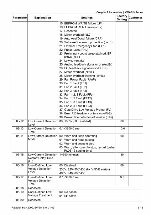
Chapter 5 Parameters|VFD-BW Series
Revision May 2009, BWE0, SW V1.05 5-13
Parameter Explanation Settings Factory Setting Customer
15: EEPROM WRITE failure (cF1) 16: EEPROM READ failure (cF2) 17: Reserved 18: Motor overload (oL2) 19: Auto Acel/Decel failure (CFA) 20: Software/Password protection (codE) 21: External Emergency Stop (EF1) 22: Phase-Loss (PHL) 23: Preliminary count value attained, EF
active (cEF)
24: Low current (Lc) 25: Analog feedback signal error (AnLEr) 26: PG feedback signal error (PGErr) 27: Motor overheat (oH9F) 28: Motor overheat warning (oH9L) 29: Fan Power Fault (FAnP) 30: Fan 1 Fault (FF1) 31: Fan 2 Fault (FF2) 32: Fan 3 Fault (FF3) 33: Fan 1, 2, 3 Fault (FFo) 34: Fan 1, 2 Fault (FF12) 35: Fan 1, 3 Fault (FF13) 36: Fan 2, 3 Fault (FF23) 37: Gate Drive Low Voltage Protect (Fv) 38: Error PID feedback of tension (rFbE) 39: Broken line detection of tension (rLbr)
06-12 Low Current Detection Level
00~100% (00: Disabled) 00
06-13 Low Current Detection Time
0.1~3600.0 sec 10.0
00: Warn and keep operating 00 06-14 Low Current Detection Mode 01: Warn and ramp to stop
02: Warn and coast to stop 03: Warn, after coast to stop, restart (delay
Pr.06-15 setting time)
06-15 Low Current Detection Restart Delay Time (Lv)
1~600 minutes 10
00: Disabled 00 230V: 220~300VDC (for VFD-B series)
06-16 User-Defined Low-Voltage Detection Level 460V: 440~600VDC
06-17 User-Defined Low-Voltage Detection Time
0.1~3600.0 sec 0.5
06-18 Reserved 00: No action 06-19 User-Defined Low-
Voltage Treatment 01: EF active 06-20 Reserved
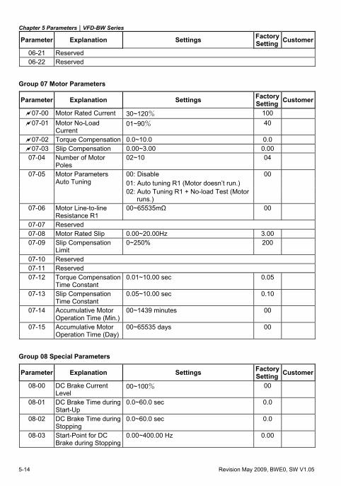
Chapter 5 Parameters|VFD-BW Series
5-14 Revision May 2009, BWE0, SW V1.05
Parameter Explanation Settings Factory Setting Customer
06-21 Reserved 06-22 Reserved
Group 07 Motor Parameters
Parameter Explanation Settings Factory Setting Customer
07-00 Motor Rated Current 30~120% 100
07-01 Motor No-Load Current
01~90% 40
07-02 Torque Compensation 0.0~10.0 0.0
07-03 Slip Compensation 0.00~3.00 0.00
07-04 Number of Motor Poles
02~10 04
00: Disable 00 07-05 Motor Parameters Auto Tuning 01: Auto tuning R1 (Motor doesn’t run.)
02: Auto Tuning R1 + No-load Test (Motor runs.)
07-06 Motor Line-to-line Resistance R1
00~65535mΩ 00
07-07 Reserved 07-08 Motor Rated Slip 0.00~20.00Hz 3.00
07-09 Slip Compensation Limit
0~250% 200
07-10 Reserved 07-11 Reserved 07-12 Torque Compensation
Time Constant 0.01~10.00 sec 0.05
07-13 Slip Compensation Time Constant
0.05~10.00 sec 0.10
07-14 Accumulative Motor Operation Time (Min.)
00~1439 minutes 00
07-15 Accumulative Motor Operation Time (Day)
00~65535 days 00
Group 08 Special Parameters
Parameter Explanation Settings Factory Setting Customer
08-00 DC Brake Current Level
00~100% 00
08-01 DC Brake Time during Start-Up
0.0~60.0 sec 0.0
08-02 DC Brake Time during Stopping
0.0~60.0 sec 0.0
08-03 Start-Point for DC Brake during Stopping
0.00~400.00 Hz 0.00
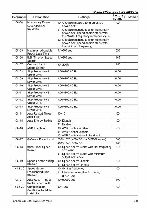
Chapter 5 Parameters|VFD-BW Series
Revision May 2009, BWE0, SW V1.05 5-15
Parameter Explanation Settings Factory Setting Customer
00: Operation stops after momentary power loss
00 08-04 Momentary Power Loss Operation Selection 01: Operation continues after momentary
power loss, speed search starts with the Master Frequency reference value.
02: Operation continues after momentary power loss, speed search starts with the minimum frequency.
08-05 Maximum Allowable Power Loss Time
0.1~5.0 sec 2.0
08-06 B.B. Time for Speed Search
0.1~5.0 sec 0.5
08-07 Current Limit for Speed Search
30~200% 150
08-08 Skip Frequency 1 Upper Limit
0.00~400.00 Hz 0.00
08-09 Skip Frequency 1 Lower Limit
0.00~400.00 Hz 0.00
08-10 Skip Frequency 2 Upper Limit
0.00~400.00 Hz 0.00
08-11 Skip Frequency 2 Lower Limit
0.00~400.00 Hz 0.00
08-12 Skip Frequency 3 Upper Limit
0.00~400.00 Hz 0.00
08-13 Skip Frequency 3 Lower Limit
0.00~400.00 Hz 0.00
08-14 Auto Restart Times After Fault
00~10 00
08-15 Auto Energy Saving 00: Disable 00 01: Enable
08-16 AVR Function 00: AVR function enable 00 01: AVR function disable 02: AVR function disable for decel.
08-17 Software Brake Level 230V: 370~430VDC (for VFD-B series) 380 460V: 740~860VDC 760
08-18 Base Block Speed Search
00: Speed search starts with last frequency command
00
01: Speed search starts with minimum output frequency
00: Speed search disable 00 08-19 Speed Search during Start-up 01: Speed search enable
00: Setting frequency 00 08-20 Speed Search Frequency during Start-up
01: Maximum operation frequency (Pr.01-00)
08-21 Auto Reset Time at Restart after Fault
00~60000 sec 600
08-22 Compensation Coefficient for Motor Instability
00~1000 00
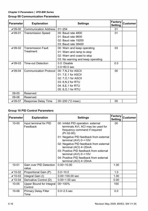
Chapter 5 Parameters|VFD-BW Series
5-16 Revision May 2009, BWE0, SW V1.05
Group 09 Communication Parameters
Parameter Explanation Settings Factory Setting Customer
09-00 Communication Address 01~254 01 09-01 Transmission Speed 00: Baud rate 4800 01
01: Baud rate 9600 02: Baud rate 19200 03: Baud rate 38400
00: Warn and keep operating 03 09-02 Transmission Fault Treatment 01: Warn and ramp to stop
02: Warn and coast to stop 03: No warning and keep operating
09-03 Time-out Detection 0.0: Disable 0.0 0.0~60.0 sec
09-04 Communication Protocol 00: 7,N,2 for ASCII 00 01: 7,E,1 for ASCII 02: 7,O,1 for ASCII 03: 8,N,2 for RTU 04: 8,E,1 for RTU 05: 8,O,1 for RTU
09-05 Reserved 09-06 Reserved 09-07 Response Delay Time 00~200 (*2 msec) 00
Group 10 PID Control Parameters
Parameter Explanation Settings Factory Setting Customer
00: Inhibit PID operation: external terminals AVI, ACI may be used for frequency command if required (Pr.02-00).
00 10-00 Input terminal for PID Feedback
01: Negative PID feedback from external terminal (AVI) 0~+10V
02: Negative PID feedback from external terminal (ACI) 4~20mA
03: Positive PID feedback from external terminal (AVI) 0~+10V
04: Positive PID feedback from external terminal (ACI) 4~20mA
10-01 Gain over PID Detection value
0.00~10.00 1.00
10-02 Proportional Gain (P) 0.0~10.0 1.0 10-03 Integral Gain (I) 0.00~100.00 sec 1.00 10-04 Derivative Control (D) 0.00~1.00 sec 0.00
10-05 Upper Bound for Integral Control
00~100% 100
10-06 Primary Delay Filter Time
0.0~2.5 sec 0.0
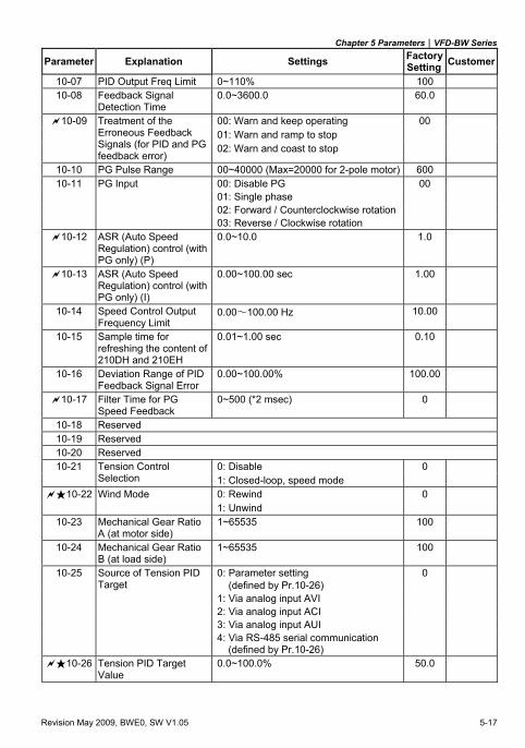
Chapter 5 Parameters|VFD-BW Series
Revision May 2009, BWE0, SW V1.05 5-17
Parameter Explanation Settings Factory Setting Customer
10-07 PID Output Freq Limit 0~110% 100 10-08 Feedback Signal
Detection Time 0.0~3600.0 60.0
00: Warn and keep operating 00 01: Warn and ramp to stop
10-09 Treatment of the Erroneous Feedback Signals (for PID and PG feedback error)
02: Warn and coast to stop
10-10 PG Pulse Range 00~40000 (Max=20000 for 2-pole motor) 600 10-11 PG Input 00: Disable PG 00
01: Single phase 02: Forward / Counterclockwise rotation 03: Reverse / Clockwise rotation
10-12 ASR (Auto Speed Regulation) control (with PG only) (P)
0.0~10.0 1.0
10-13 ASR (Auto Speed Regulation) control (with PG only) (I)
0.00~100.00 sec 1.00
10-14 Speed Control Output Frequency Limit
0.00∼100.00 Hz 10.00
10-15 Sample time for refreshing the content of 210DH and 210EH
0.01~1.00 sec 0.10
10-16 Deviation Range of PID Feedback Signal Error
0.00~100.00% 100.00
10-17 Filter Time for PG Speed Feedback
0~500 (*2 msec) 0
10-18 Reserved 10-19 Reserved 10-20 Reserved
0: Disable 10-21 Tension Control Selection 1: Closed-loop, speed mode
0
0: Rewind 10 -22 Wind Mode 1: Unwind
0
10-23 Mechanical Gear Ratio A (at motor side)
1~65535 100
10-24 Mechanical Gear Ratio B (at load side)
1~65535 100
10-25 Source of Tension PID Target
0: Parameter setting (defined by Pr.10-26)
0
1: Via analog input AVI 2: Via analog input ACI 3: Via analog input AUI 4: Via RS-485 serial communication
(defined by Pr.10-26)
10 -26 Tension PID Target Value
0.0~100.0% 50.0
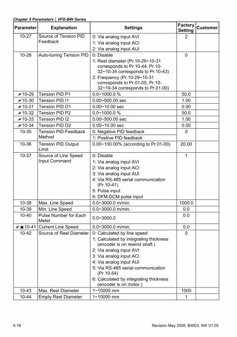
Chapter 5 Parameters|VFD-BW Series
5-18 Revision May 2009, BWE0, SW V1.05
Parameter Explanation Settings Factory Setting Customer
0: Via analog input AVI 2 10-27 Source of Tension PID Feedback 1: Via analog input ACI
2: Via analog input AUI 10-28 Auto-tuning Tension PID 0: Disable 0
1: Reel diameter (Pr.10-29~10-31 corresponds to Pr.10-44, Pr.10-32~10-34 corresponds to Pr.10-43)
2: Frequency (Pr.10-29~10-31 corresponds to Pr.01-05, Pr.10-32~10-34 corresponds to Pr.01-00)
10-29 Tension PID P1 0.0~1000.0 % 50.0 10-30 Tension PID I1 0.00~500.00 sec 1.00 10-31 Tension PID D1 0.00~10.00 sec 0.00 10-32 Tension PID P2 0.0~1000.0 % 50.0 10-33 Tension PID I2 0.00~500.00 sec 1.00 10-34 Tension PID D2 0.00~10.00 sec 0.00
0: Negative PID feedback 0 10-35 Tension PID Feedback Method 1: Positive PID feedback
10-36 Tension PID Output Limit
0.00~100.00% (according to Pr.01-00) 20.00
0: Disable 1 10-37 Source of Line Speed Input Command 1: Via analog input AVI
2: Via analog input ACI 3: Via analog input AUI 4: Via RS-485 serial communication
(Pr.10-41)
5: Pulse input 6: DFM-DCM pulse input
10-38 Max. Line Speed 0.0~3000.0 m/min. 1000.0 10-39 Min. Line Speed 0.0~3000.0 m/min. 0.0 10-40 Pulse Number for Each
Meter 0.0~3000.0 0.0
10 -41 Current Line Speed 0.0~3000.0 m/min. 0.0 10-42 Source of Reel Diameter 0: Calculated by line speed 0
1: Calculated by integrating thickness (encoder is on rewind shaft.)
2: Via analog input AVI 3: Via analog input ACI 4: Via analog input AUI 5: Via RS-485 serial communication
(Pr.10-54)
6: Calculated by integrating thickness (encoder is on motor.)
10-43 Max. Reel Diameter 1~10000 mm 1000 10-44 Empty Reel Diameter 1~10000 mm 1
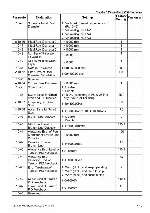
Chapter 5 Parameters|VFD-BW Series
Revision May 2009, BWE0, SW V1.05 5-19
Parameter Explanation Settings Factory Setting Customer
10-45 Source of Initial Reel Diameter
0: Via RS-485 serial communication (Pr.10-46)
0
1: Via analog input AVI 2: Via analog input ACI 3: Via analog input AUI
10 -46 Initial Reel Diameter 0 1~10000 mm 1 10-47 Initial Reel Diameter 1 1~10000 mm 1 10-48 Initial Reel Diameter 2 1~10000 mm 1 10-49 Number of Pulse per
Revolution 1~10000 1
10-50 Coil Number for Each Layer 1~10000 1
10-51 Material Thickness 0.001~60.000 mm 0.001 10-52 Filter Time of Reel
Diameter Calculation 0.00~100.00 sec 1.00
10-53 Reserved 10 -54 Current Reel Diameter 1~10000 mm 1
10-55 Smart Start 0: Disable 0 1: Enable
10-56 Switch Level for Smart Start and PID function
0~100% (according to Pr.10-26 PID Target Value of Tension)
15.0
10-57 Frequency for Smart Start 0.10~400.00Hz 2.00
10-58 Accel. Time for Smart Start 0.1~3600.0 sec/0.01~3600.00 sec 3.0
10-59 Broken Line Detection 0: Disable 0 1: Enable
10-60 Min. Line Speed of Broken Line Detection 0.1~3000.0 m/min. 200.0
10-61 Allowance Error of Reel Diameter of Broken Line Detection
1~10000 mm 100
10-62 Detection Time of Broken Line 0.1~1000.0 sec 0.5
10-63 Allowance Error Level of Tension PID Feedback 0.0~100.0% 100.0
10-64 Allowance Error Detection Time of Tension PID Feedback
0.1~1000.0 sec 0.5
0: Warn (rFbE) and keep operating 2 10-65 Error Treatment of Tension PID Feedback 1: Warn (rFbE) and ramp to stop
2: Warn (rFbE) and coast to stop 10-66 Upper Limit of Tension
PID Feedback 0.0~100.0% 100.0
10-67 Lower Limit of Tension PID Feedback 0.0~100.0% 0.0
10-68 Reserved
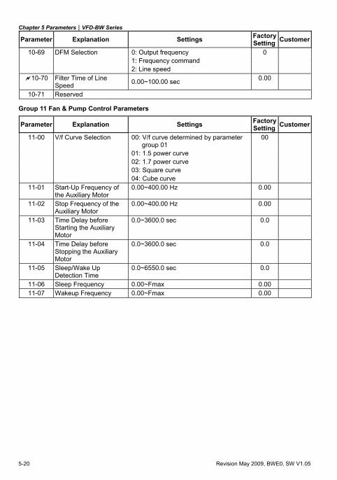
Chapter 5 Parameters|VFD-BW Series
5-20 Revision May 2009, BWE0, SW V1.05
Parameter Explanation Settings Factory Setting Customer
10-69 DFM Selection 0: Output frequency 0 1: Frequency command 2: Line speed
10-70 Filter Time of Line Speed 0.00~100.00 sec 0.00
10-71 Reserved
Group 11 Fan & Pump Control Parameters
Parameter Explanation Settings Factory Setting Customer
11-00 V/f Curve Selection 00: V/f curve determined by parameter group 01
00
01: 1.5 power curve 02: 1.7 power curve 03: Square curve 04: Cube curve
11-01 Start-Up Frequency of the Auxiliary Motor
0.00~400.00 Hz 0.00
11-02 Stop Frequency of the Auxiliary Motor
0.00~400.00 Hz 0.00
11-03 Time Delay before Starting the Auxiliary Motor
0.0~3600.0 sec 0.0
11-04 Time Delay before Stopping the Auxiliary Motor
0.0~3600.0 sec 0.0
11-05 Sleep/Wake Up Detection Time
0.0~6550.0 sec 0.0
11-06 Sleep Frequency 0.00~Fmax 0.00 11-07 Wakeup Frequency 0.00~Fmax 0.00
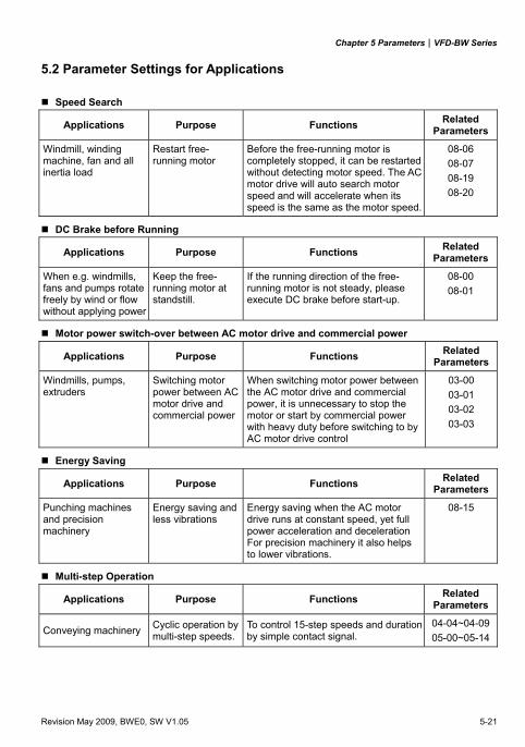
Chapter 5 Parameters|VFD-BW Series
Revision May 2009, BWE0, SW V1.05 5-21
5.2 Parameter Settings for Applications
Speed Search
Applications Purpose Functions Related Parameters
Windmill, winding machine, fan and all inertia load
Restart free-running motor
Before the free-running motor is completely stopped, it can be restarted without detecting motor speed. The AC motor drive will auto search motor speed and will accelerate when its speed is the same as the motor speed.
08-06 08-07 08-19 08-20
DC Brake before Running
Applications Purpose Functions Related Parameters
When e.g. windmills, fans and pumps rotate freely by wind or flow without applying power
Keep the free-running motor at standstill.
If the running direction of the free-running motor is not steady, please execute DC brake before start-up.
08-00 08-01
Motor power switch-over between AC motor drive and commercial power
Applications Purpose Functions Related Parameters
Windmills, pumps, extruders
Switching motor power between AC motor drive and commercial power
When switching motor power between the AC motor drive and commercial power, it is unnecessary to stop the motor or start by commercial power with heavy duty before switching to by AC motor drive control
03-00 03-01 03-02 03-03
Energy Saving
Applications Purpose Functions Related Parameters
Punching machines and precision machinery
Energy saving and less vibrations
Energy saving when the AC motor drive runs at constant speed, yet full power acceleration and deceleration For precision machinery it also helps to lower vibrations.
08-15
Multi-step Operation
Applications Purpose Functions Related Parameters
Conveying machinery Cyclic operation by multi-step speeds.
To control 15-step speeds and duration by simple contact signal.
04-04~04-0905-00~05-14
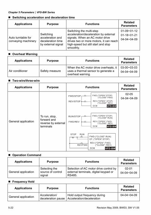
Chapter 5 Parameters|VFD-BW Series
5-22 Revision May 2009, BWE0, SW V1.05
Switching acceleration and deceleration time
Applications Purpose Functions Related Parameters
Auto turntable for conveying machinery
Switching acceleration and deceleration time by external signal
Switching the multi-step acceleration/deceleration by external signals. When an AC motor drive drives two or more motors, it can reach high-speed but still start and stop smoothly.
01-09~01-1201-18~01-2104-04~04-09
Overheat Warning
Applications Purpose Functions Related Parameters
Air conditioner Safety measure When the AC motor drive overheats, it uses a thermal sensor to generate a overheat warning.
03-00~03-0304-04~04-09
Two-wire/three-wire
Applications Purpose Functions Related Parameters
General application
To run, stop, forward and reverse by external terminals
VFD-BW
FWD:("OPEN":STOP)("CLOSE":FWD)
REV:("OPEN": STOP)("CLOSE": REV)
DCM
FWD/STOP
REV/STOP
VFD-BW
FWD:("OPEN":STOP)("CLOSE":RUN)
REV:("OPEN": F("CLOSE": REV)
DCM
RUN/STOP
FWD/REV WD)
VFD-BW
FWD:("CLOSE":RUN)EF: ("OPEN":STOP)
REV:("OPEN": F("CLOSE": REV)
DCM
STOP RUN
REV/FWDWD)
02-05 04-04~04-09
Operation Command
Applications Purpose Functions Related Parameters
General application Selecting the source of control signal
Selection of AC motor drive control by external terminals, digital keypad or RS485.
02-01 04-04~04-09
Frequency Hold
Applications Purpose Functions Related Parameters
General application Acceleration/ deceleration pause
Hold output frequency during Acceleration/deceleration
04-04~04-09
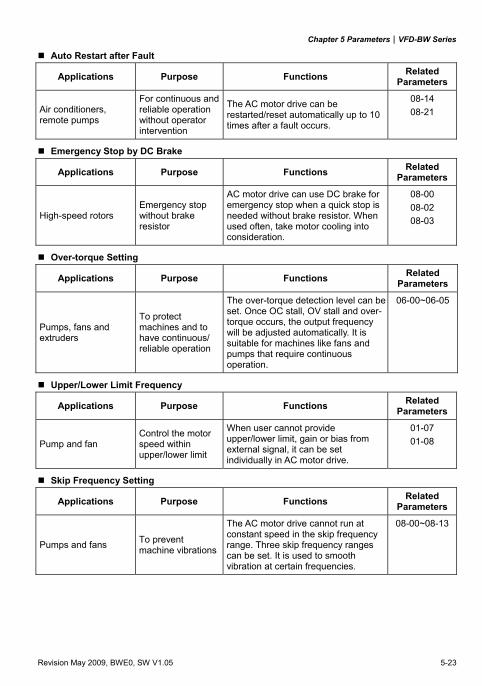
Chapter 5 Parameters|VFD-BW Series
Revision May 2009, BWE0, SW V1.05 5-23
Auto Restart after Fault
Applications Purpose Functions Related Parameters
Air conditioners, remote pumps
For continuous and reliable operation without operator intervention
The AC motor drive can be restarted/reset automatically up to 10 times after a fault occurs.
08-14 08-21
Emergency Stop by DC Brake
Applications Purpose Functions Related Parameters
High-speed rotors Emergency stop without brake resistor
AC motor drive can use DC brake for emergency stop when a quick stop is needed without brake resistor. When used often, take motor cooling into consideration.
08-00 08-02 08-03
Over-torque Setting
Applications Purpose Functions Related Parameters
Pumps, fans and extruders
To protect machines and to have continuous/ reliable operation
The over-torque detection level can be set. Once OC stall, OV stall and over-torque occurs, the output frequency will be adjusted automatically. It is suitable for machines like fans and pumps that require continuous operation.
06-00~06-05
Upper/Lower Limit Frequency
Applications Purpose Functions Related Parameters
Pump and fan Control the motor speed within upper/lower limit
When user cannot provide upper/lower limit, gain or bias from external signal, it can be set individually in AC motor drive.
01-07 01-08
Skip Frequency Setting
Applications Purpose Functions Related Parameters
Pumps and fans To prevent machine vibrations
The AC motor drive cannot run at constant speed in the skip frequency range. Three skip frequency ranges can be set. It is used to smooth vibration at certain frequencies.
08-00~08-13
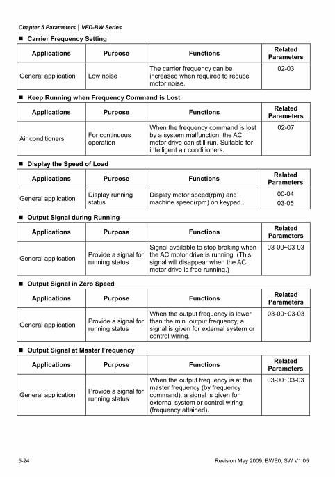
Chapter 5 Parameters|VFD-BW Series
5-24 Revision May 2009, BWE0, SW V1.05
Carrier Frequency Setting
Applications Purpose Functions Related Parameters
General application Low noise The carrier frequency can be increased when required to reduce motor noise.
02-03
Keep Running when Frequency Command is Lost
Applications Purpose Functions Related Parameters
Air conditioners For continuous operation
When the frequency command is lost by a system malfunction, the AC motor drive can still run. Suitable for intelligent air conditioners.
02-07
Display the Speed of Load
Applications Purpose Functions Related Parameters
General application Display running status
Display motor speed(rpm) and machine speed(rpm) on keypad.
00-04 03-05
Output Signal during Running
Applications Purpose Functions Related Parameters
General application Provide a signal for running status
Signal available to stop braking when the AC motor drive is running. (This signal will disappear when the AC motor drive is free-running.)
03-00~03-03
Output Signal in Zero Speed
Applications Purpose Functions Related Parameters
General application Provide a signal for running status
When the output frequency is lower than the min. output frequency, a signal is given for external system or control wiring.
03-00~03-03
Output Signal at Master Frequency
Applications Purpose Functions Related Parameters
General application Provide a signal for running status
When the output frequency is at the master frequency (by frequency command), a signal is given for external system or control wiring (frequency attained).
03-00~03-03
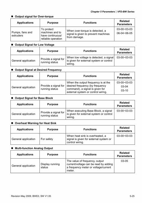
Chapter 5 Parameters|VFD-BW Series
Revision May 2009, BWE0, SW V1.05 5-25
Output signal for Over-torque
Applications Purpose Functions Related Parameters
Pumps, fans and extruders
To protect machines and to have continuous/ reliable operation
When over-torque is detected, a signal is given to prevent machines from damage.
03-00~03-0306-04~06-05
Output Signal for Low Voltage
Applications Purpose Functions Related Parameters
General application Provide a signal for running status
When low voltage is detected, a signal is given for external system or control wiring.
03-00~03-03
Output Signal at Desired Frequency
Applications Purpose Functions Related Parameters
General application Provide a signal for running status
When the output frequency is at the desired frequency (by frequency command), a signal is given for external system or control wiring.
03-00~03-0303-04 03-10
Output Signal for Base Block
Applications Purpose Functions Related Parameters
General application Provide a signal for running status
When executing Base Block, a signal is given for external system or control wiring.
03-00~03-03
Overheat Warning for Heat Sink
Applications Purpose Functions Related Parameters
General application For safety When heat sink is overheated, a signal is given for external system or control wiring.
03-00~03-03
Multi-function Analog Output
Applications Purpose Functions Related Parameters
General application Display running status
The value of frequency, output current/voltage can be read by adding a frequency meter or voltage/current meter.
03-05
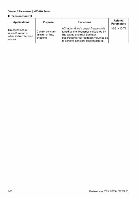
Chapter 5 Parameters|VFD-BW Series
5-26 Revision May 2009, BWE0, SW V1.05
Tension Control
Applications Purpose Functions Related Parameters
On occasions of rewind/unwind or other indirect tension control
Control constant tension of line, sheeting
AC motor drive’s output frequency is tuned by the frequency calculated by line speed and reel diameter superposing PID feedback value so as to achieve constant tension control.
10-21~10-71
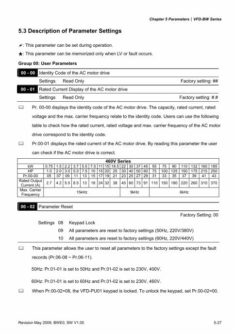
Chapter 5 Parameters|VFD-BW Series
Revision May 2009, BWE0, SW V1.05 5-27
5.3 Description of Parameter Settings
: This parameter can be set during operation.
: This parameter can be memorized only when LV or fault occurs.
Group 00: User Parameters
00 - 00 Identity Code of the AC motor drive
Settings Read Only Factory setting: ##
00 - 01 Rated Current Display of the AC motor drive
Settings Read Only Factory setting: #.#
Pr. 00-00 displays the identity code of the AC motor drive. The capacity, rated current, rated
voltage and the max. carrier frequency relate to the identity code. Users can use the following
table to check how the rated current, rated voltage and max. carrier frequency of the AC motor
drive correspond to the identity code.
Pr.00-01 displays the rated current of the AC motor drive. By reading this parameter the user
can check if the AC motor drive is correct.
460V Series kW 0.75 1.5 2.2 3.7 5.5 7.5 11 15 18.5 22 30 37 45 55 75 90 110 132 160 185HP 1.0 2.0 3.0 5.0 7.5 10 15 20 25 30 40 50 60 75 100 125 150 175 215 250
Pr.00-00 05 07 09 11 13 15 17 19 21 23 25 27 29 31 33 35 37 39 41 43Rated Output Current (A) 2.7 4.2 5.5 8.5 13 18 24 32 38 45 60 73 91 110 150 180 220 260 310 370
Max. Carrier Frequency 15kHz 9kHz 6kHz
00 - 02 Parameter Reset
Factory Setting: 00
Settings 08 Keypad Lock
09 All parameters are reset to factory settings (50Hz, 220V/380V)
10 All parameters are reset to factory settings (60Hz, 220V/440V)
This parameter allows the user to reset all parameters to the factory settings except the fault
records (Pr.06-08 ~ Pr.06-11).
50Hz: Pr.01-01 is set to 50Hz and Pr.01-02 is set to 230V, 400V.
60Hz: Pr.01-01 is set to 60Hz and Pr.01-02 is set to 230V, 460V. When Pr.00-02=08, the VFD-PU01 keypad is locked. To unlock the keypad, set Pr.00-02=00.
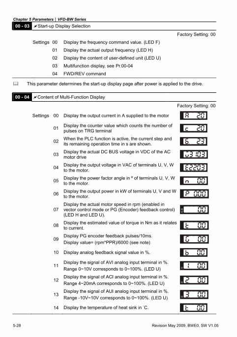
Chapter 5 Parameters|VFD-BW Series
5-28 Revision May 2009, BWE0, SW V1.05
00 - 03 Start-up Display Selection
Factory Setting: 00
Settings 00 Display the frequency command value. (LED F)
01 Display the actual output frequency (LED H)
02 Display the content of user-defined unit (LED U)
03 Multifunction display, see Pr.00-04
04 FWD/REV command
This parameter determines the start-up display page after power is applied to the drive.
00 - 04 Content of Multi-Function Display
Factory Setting: 00
Settings 00 Display the output current in A supplied to the motor
01 Display the counter value which counts the number of pulses on TRG terminal
02 When the PLC function is active, the current step and its remaining operation time in s are shown.
03 Display the actual DC BUS voltage in VDC of the AC motor drive
04 Display the output voltage in VAC of terminals U, V, W to the motor.
05 Display the power factor angle in º of terminals U, V, W to the motor.
06 Display the output power in kW of terminals U, V and W to the motor.
07 Display the actual motor speed in rpm (enabled in vector control mode or PG (Encoder) feedback control) (LED H and LED U).
08 Display the estimated value of torque in Nm as it relates to current.
09 Display PG encoder feedback pulses/10ms. Display value= (rpm*PPR)/6000 (see note)
10 Display analog feedback signal value in %.
11 Display the signal of AVI analog input terminal in %. Range 0~10V corresponds to 0~100%. (LED U)
12 Display the signal of ACI analog input terminal in %. Range 4~20mA corresponds to 0~100%. (LED U)
13 Display the signal of AUI analog input terminal in %. Range -10V~10V corresponds to 0~100%. (LED U)
14 Display the temperature of heat sink in °C.
Chapter 5 Parameters|VFD-BW Series
Revision May 2009, BWE0, SW V1.05 5-29
This parameter sets the display when Pr. 00-03 is set to 03.
Pr.00-04=09. The display value is (((rpm/60)*PPR)/1000ms)*10ms
with rpm=motor speed in revs/min and PPR=encoder pulse per revolution
When the display shows the multi-function display (Pr.00-03=03), the user also can view other
information by pressing the “LEFT” key on the VFD-PU01 keypad. 00-05 User Defined Coefficient K Unit: 0.01
Settings 0.01 to 160.00 Factory Setting: 1.00
The coefficient K determines the multiplying factor for the user-defined unit.
The display value is calculated as follows:
U (User-defined unit) = Frequency Command * K (Pr.00-05)
H (actual output) = Actual output frequency * K (Pr.00-05)
Example:
A conveyor belt runs at 13.6m/s at motor speed 60Hz.
K = 13.6/60 = 0.23 (0.226667 rounded to 2 decimals), therefore Pr.00-05=0.23
With Frequency command 35Hz, display shows LED U and 35*0.23=8.05m/s.
(To increase accuracy, use K=2.27 or K=22.67 and disregard decimal point.) 00 - 06 Software Version
Settings Read Only
Display #.## 00 - 07 Password Input Unit: 1
Settings 00 to 65535 Factory Setting: 00
Display 00~02 (times of wrong password)
The function of this parameter is to input the password that is set in Pr.00-08. Input the correct
password here to enable changing parameters. You are limited to a maximum of 3 attempts.
After 3 consecutive failed attempts, a blinking “PcodE” will show up to force the user to restart
the AC motor drive in order to try again to input the correct password. 00 - 08 Password Set Unit: 1
Settings 00 to 65535 Factory Setting: 00
Display 00 No password set or successful input in Pr. 00-07
01 Password has been set
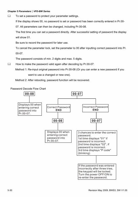
Chapter 5 Parameters|VFD-BW Series
5-30 Revision May 2009, BWE0, SW V1.05
To set a password to protect your parameter settings.
If the display shows 00, no password is set or password has been correctly entered in Pr.00-
07. All parameters can then be changed, including Pr.00-08.
The first time you can set a password directly. After successful setting of password the display
will show 01.
Be sure to record the password for later use.
To cancel the parameter lock, set the parameter to 00 after inputting correct password into Pr.
00-07.
The password consists of min. 2 digits and max. 5 digits.
How to make the password valid again after decoding by Pr.00-07:
Method 1: Re-input original password into Pr.00-08 (Or you can enter a new password if you
want to use a changed or new one).
Method 2: After rebooting, password function will be recovered.
Password Decode Flow Chart
3 chances to enter the correctpassword.1st time displays "01" ifpassword is incorrect.2nd time displays "02", ifpassword is incorrect.3rd time displays "P code"(blinking)
If the password was entered incorrectly after three tries,the keypad will be locked.Turn the power OFF/ON tore-enter the password.
Incorrect PasswordEND
Displays 00 whenentering correctpassword into Pr.00-07.
00-08 00-07
00-07
Displays 00 whenentering correctpassword into Pr.00-07.
Correct PasswordEND
00-08
Chapter 5 Parameters|VFD-BW Series
Revision May 2009, BWE0, SW V1.05 5-31
00 - 09 Control method Factory Setting: 00
Settings 00 V/f control
01 V/f + PG Control
02 Vector Control
03 Vector + PG Control
This parameter determines the control method of the AC motor drive.
PG is encoder (Pulse Generator) feedback for which an optional PG card is required.
00 - 10 Reserved
Chapter 5 Parameters|VFD-BW Series
5-32 Revision May 2009, BWE0, SW V1.05
Group 01: Basic Parameters
01 - 00 Maximum Output Frequency (Fmax) Unit: 0.01
Settings 50.00 to 400.00Hz Factory Setting: 60.00
This parameter determines the AC motor drive’s Maximum Output Frequency. All the AC
motor drive frequency command sources (analog inputs 0 to +10V, 4 to 20mA and -10V to
+10V) are scaled to correspond to the output frequency range. 01 - 01 Maximum Voltage Frequency (Fbase) Unit: 0.01
Settings 0.10 to 400.00Hz Factory Setting: 60.00
This value should be set according to the rated frequency of the motor as indicated on the
motor nameplate. Maximum Voltage Frequency determines the v/f curve ratio. For example, if
the drive is rated for 460 VAC output and the Maximum Voltage Frequency is set to 60Hz, the
drive will maintain a constant ratio of 7.66 V/Hz (460V/60Hz=7.66V/Hz). This parameter value
must be equal to or greater than the Mid-Point Frequency (Pr.01-03).
01 - 02 Maximum Output Voltage (Vmax) Unit: 0.1
Settings 230V series 0.1 to 255.0V Factory Setting: 220.0
460V series 0.1 to 510.0V Factory Setting: 440.0
This parameter determines the Maximum Output Voltage of the AC motor drive. The Maximum
Output Voltage setting must be smaller than or equal to the rated voltage of the motor as
indicated on the motor nameplate. This parameter value must be equal to or greater than the
Mid-Point Voltage (Pr.01-04). 01 - 03 Mid-Point Frequency (Fmid) Unit: 0.01
Settings 0.10 to 400.00Hz Factory Setting: 0.50
This parameter sets the Mid-Point Frequency of the V/f curve. With this setting, the V/f ratio
between Minimum Frequency and Mid-Point frequency can be determined. This parameter
must be equal to or greater than Minimum Output Frequency (Pr.01-05) and equal to or less
than Maximum Voltage Frequency (Pr.01-01).
This parameter is ineffective when Pr.11-00 is set to 1 to 4.
The settings of 01-03, 01-04, and 01-06 are invalid in vector control mode.
Chapter 5 Parameters|VFD-BW Series
Revision May 2009, BWE0, SW V1.05 5-33
01 - 04 Mid-Point Voltage (Vmid) Unit: 0.1
Settings 230V series 0.1 to 255.0V Factory Setting: 1.7V
460V series 0.1 to 510.0V Factory Setting: 3.4V
This parameter sets the Mid-Point Voltage of any V/f curve. With this setting, the V/f ratio
between Minimum Frequency and Mid-Point Frequency can be determined. This parameter
must be equal to or greater than Minimum Output Voltage (Pr.01-06) and equal to or less than
Maximum Output Voltage (Pr.01-02).
This parameter is ineffective when Pr.11-00 is set to 1 to 4.
The settings of 01-03, 01-04, and 01-06 are invalid in vector control mode.
01 - 05 Minimum Output Frequency (Fmin) Unit: 0.01
Settings 0.10 to 400.00Hz Factory Setting: 0.50
This parameter sets the Minimum Output Frequency of the AC motor drive. This parameter
must be equal to or less than Mid-Point Frequency (Pr.01-03).
01 - 06 Minimum Output Voltage (Vmin) Unit: 0.1
Settings 230V series 0.1 to 255.0V Factory Setting: 1.7V
460V series 0.1 to 510.0V Factory Setting: 3.4V
This parameter sets the Minimum Output Voltage of the AC motor drive. This parameter must
be equal to or less than Mid-Point Voltage (Pr.01-04).
The settings of Pr.01-01 to Pr.01-06 have to meet the condition of Pr.01-02 ≥ Pr.01-04 ≥ Pr.01-
06 and Pr.01-01 ≥ Pr.01-03 ≥ Pr.01-05.
In vector control mode, the settings of 01-03, 01-04, and 01-06 are invalid, whereas, Pr.01-05
is still the Minimum Output Frequency of the AC motor drive.
01 - 07 Output Frequency Upper Limit Unit: 1
Settings 01 to 120% Factory Setting: 100
This parameter must be equal to or greater than the Output Frequency Lower Limit (Pr.01-08).
The Maximum Output Frequency (Pr.01-00) is regarded as 100%.
Output Frequency Upper Limit value = (Pr.01-00 * Pr.01-07)/100.
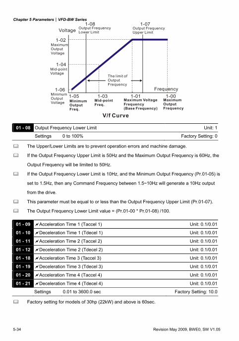
Chapter 5 Parameters|VFD-BW Series
5-34 Revision May 2009, BWE0, SW V1.05
1-05 1-03 1-011-06
1-04
1-02
1-00
1-071-08
V/f Curve
Voltage
Frequency
Output FrequencyLower Limit
Output FrequencyUpper Limit
The limit of Output Frequency
Mid-point Freq.
Maximum OutputFrequency
MaximumOutputVoltage
Mid-pointVoltage
MinimumOutputVoltage Minimum
OutputFreq.
Maximum VoltageFrequency(Base Frequency)
01 - 08 Output Frequency Lower Limit Unit: 1
Settings 0 to 100% Factory Setting: 0
The Upper/Lower Limits are to prevent operation errors and machine damage.
If the Output Frequency Upper Limit is 50Hz and the Maximum Output Frequency is 60Hz, the
Output Frequency will be limited to 50Hz.
If the Output Frequency Lower Limit is 10Hz, and the Minimum Output Frequency (Pr.01-05) is
set to 1.5Hz, then any Command Frequency between 1.5~10Hz will generate a 10Hz output
from the drive.
This parameter must be equal to or less than the Output Frequency Upper Limit (Pr.01-07).
The Output Frequency Lower Limit value = (Pr.01-00 * Pr.01-08) /100.
01 - 09 Acceleration Time 1 (Taccel 1) Unit: 0.1/0.01
01 - 10 Deceleration Time 1 (Tdecel 1) Unit: 0.1/0.01
01 - 11 Acceleration Time 2 (Taccel 2) Unit: 0.1/0.01
01 - 12 Deceleration Time 2 (Tdecel 2) Unit: 0.1/0.01
01 - 18 Acceleration Time 3 (Taccel 3) Unit: 0.1/0.01
01 - 19 Deceleration Time 3 (Tdecel 3) Unit: 0.1/0.01
01 - 20 Acceleration Time 4 (Taccel 4) Unit: 0.1/0.01
01 - 21 Deceleration Time 4 (Tdecel 4) Unit: 0.1/0.01
Settings 0.01 to 3600.0 sec Factory Setting: 10.0
Factory setting for models of 30hp (22kW) and above is 60sec.
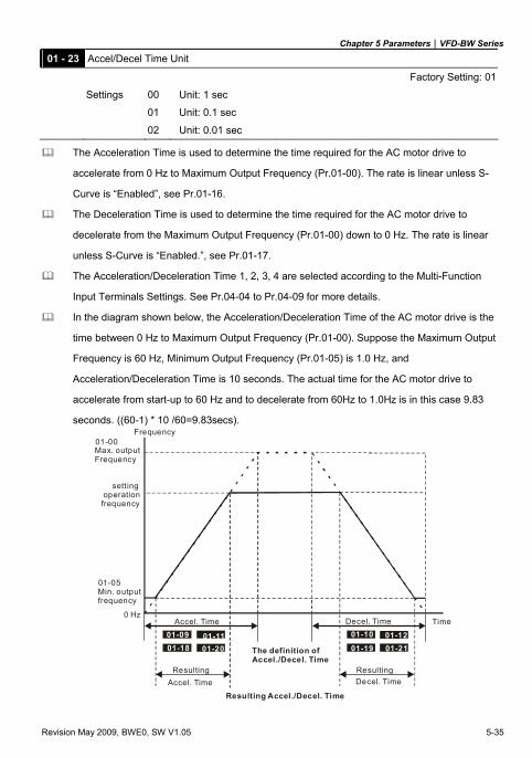
Chapter 5 Parameters|VFD-BW Series
Revision May 2009, BWE0, SW V1.05 5-35
01 - 23 Accel/Decel Time Unit
Factory Setting: 01
Settings 00 Unit: 1 sec
01 Unit: 0.1 sec
02 Unit: 0.01 sec
The Acceleration Time is used to determine the time required for the AC motor drive to
accelerate from 0 Hz to Maximum Output Frequency (Pr.01-00). The rate is linear unless S-
Curve is “Enabled”, see Pr.01-16.
The Deceleration Time is used to determine the time required for the AC motor drive to
decelerate from the Maximum Output Frequency (Pr.01-00) down to 0 Hz. The rate is linear
unless S-Curve is “Enabled.”, see Pr.01-17.
The Acceleration/Deceleration Time 1, 2, 3, 4 are selected according to the Multi-Function
Input Terminals Settings. See Pr.04-04 to Pr.04-09 for more details.
In the diagram shown below, the Acceleration/Deceleration Time of the AC motor drive is the
time between 0 Hz to Maximum Output Frequency (Pr.01-00). Suppose the Maximum Output
Frequency is 60 Hz, Minimum Output Frequency (Pr.01-05) is 1.0 Hz, and
Acceleration/Deceleration Time is 10 seconds. The actual time for the AC motor drive to
accelerate from start-up to 60 Hz and to decelerate from 60Hz to 1.0Hz is in this case 9.83
seconds. ((60-1) * 10 /60=9.83secs).
01-00
01-09 01-1101-18 01-20
01-10 01-1201-19 01-21
Frequency
TimeAccel. Time Decel. Time
The definition of Accel./Decel. Time
Max. outputFrequency
sett ing operationfrequency
Min. outputfrequency
01-05
Resulting ResultingAccel. Time Decel. Time
Resulting Accel./Decel. Time
0 Hz
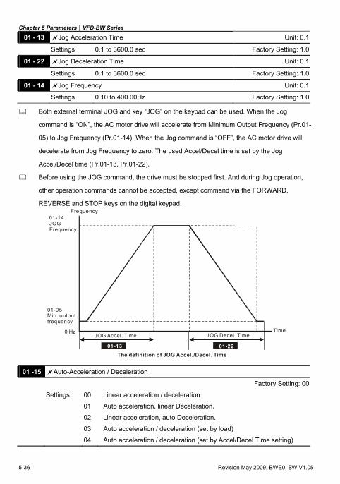
Chapter 5 Parameters|VFD-BW Series
5-36 Revision May 2009, BWE0, SW V1.05
01 - 13 Jog Acceleration Time Unit: 0.1
Settings 0.1 to 3600.0 sec Factory Setting: 1.0
01 - 22 Jog Deceleration Time Unit: 0.1
Settings 0.1 to 3600.0 sec Factory Setting: 1.0
01 - 14 Jog Frequency Unit: 0.1
Settings 0.10 to 400.00Hz Factory Setting: 1.0
Both external terminal JOG and key “JOG” on the keypad can be used. When the Jog
command is “ON”, the AC motor drive will accelerate from Minimum Output Frequency (Pr.01-
05) to Jog Frequency (Pr.01-14). When the Jog command is “OFF”, the AC motor drive will
decelerate from Jog Frequency to zero. The used Accel/Decel time is set by the Jog
Accel/Decel time (Pr.01-13, Pr.01-22).
Before using the JOG command, the drive must be stopped first. And during Jog operation,
other operation commands cannot be accepted, except command via the FORWARD,
REVERSE and STOP keys on the digital keypad.
01-13
Frequency
TimeJOG Accel. Time JOG Decel. Time
The definition of JOG Accel./Decel. Time
01-14JOGFrequency
Min. outputfrequency
01-05
0 Hz
01-22
01 -15 Auto-Acceleration / Deceleration
Factory Setting: 00
Settings 00 Linear acceleration / deceleration
01 Auto acceleration, linear Deceleration.
02 Linear acceleration, auto Deceleration.
03 Auto acceleration / deceleration (set by load)
04 Auto acceleration / deceleration (set by Accel/Decel Time setting)
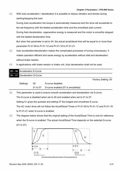
Chapter 5 Parameters|VFD-BW Series
Revision May 2009, BWE0, SW V1.05 5-37
With Auto acceleration / deceleration it is possible to reduce vibration and shocks during
starting/stopping the load.
During Auto acceleration the torque is automatically measured and the drive will accelerate to
the set frequency with the fastest acceleration time and the smoothest start current.
During Auto deceleration, regenerative energy is measured and the motor is smoothly stopped
with the fastest deceleration time.
But when this parameter is set to 04, the actual accel/decel time will be equal to or more than
parameter Pr.01-09 to Pr.01-12 and Pr.01-18 to Pr.01-21.
Auto acceleration/deceleration makes the complicated processes of tuning unnecessary. It
makes operation efficient and saves energy by acceleration without stall and deceleration
without brake resistor.
In applications with brake resistor or brake unit, Auto deceleration shall not be used.
01 - 16 Acceleration S-Curve
01 - 17 Deceleration S-Curve
Factory Setting: 00
Settings 00 S-curve disabled
01 to 07 S-curve enabled (07 is smoothest)
This parameter is used to ensure smooth acceleration and deceleration via S-curve.
The S-curve is disabled when set to 00 and enabled when set to 01 to 07.
Setting 01 gives the quickest and setting 07 the longest and smoothest S-curve.
The AC motor drive will not follow the Accel/Decel Times in Pr.01-09 to Pr.01-12 and Pr.01-18
to Pr.01-21 when S-curve is enabled.
The diagram below shows that the original setting of the Accel/Decel Time is only for reference
when the S-curve is enabled. The actual Accel/Decel Time depends on the selected S-curve
(01 to 07).
31 2
4
1
34
2
1 2Disable S curve
3 4Enable S curve
Acceleration/deceleration Characteristics
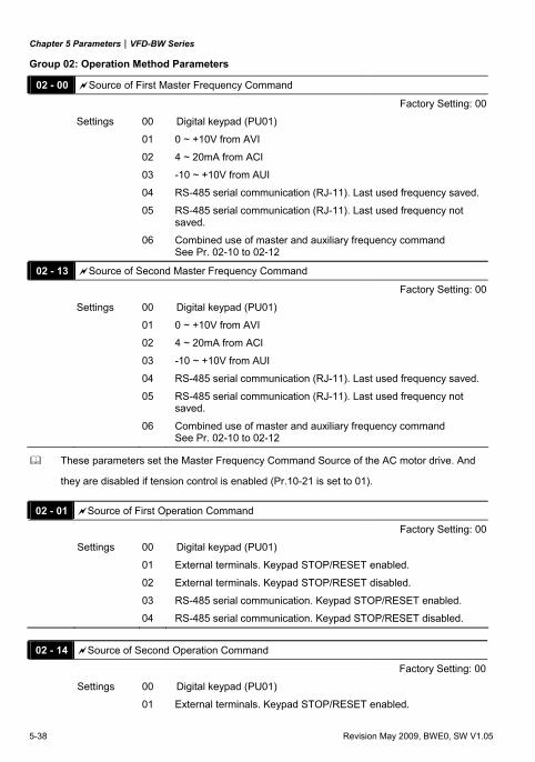
Chapter 5 Parameters|VFD-BW Series
5-38 Revision May 2009, BWE0, SW V1.05
Group 02: Operation Method Parameters
02 - 00 Source of First Master Frequency Command
Factory Setting: 00
Settings 00 Digital keypad (PU01)
01 0 ~ +10V from AVI
02 4 ~ 20mA from ACI
03 -10 ~ +10V from AUI
04 RS-485 serial communication (RJ-11). Last used frequency saved.
05 RS-485 serial communication (RJ-11). Last used frequency not saved.
06 Combined use of master and auxiliary frequency command See Pr. 02-10 to 02-12
02 - 13 Source of Second Master Frequency Command
Factory Setting: 00
Settings 00 Digital keypad (PU01)
01 0 ~ +10V from AVI
02 4 ~ 20mA from ACI
03 -10 ~ +10V from AUI
04 RS-485 serial communication (RJ-11). Last used frequency saved.
05 RS-485 serial communication (RJ-11). Last used frequency not saved.
06 Combined use of master and auxiliary frequency command See Pr. 02-10 to 02-12
These parameters set the Master Frequency Command Source of the AC motor drive. And
they are disabled if tension control is enabled (Pr.10-21 is set to 01).
02 - 01 Source of First Operation Command
Factory Setting: 00
Settings 00 Digital keypad (PU01)
01 External terminals. Keypad STOP/RESET enabled.
02 External terminals. Keypad STOP/RESET disabled.
03 RS-485 serial communication. Keypad STOP/RESET enabled.
04 RS-485 serial communication. Keypad STOP/RESET disabled.
02 - 14 Source of Second Operation Command
Factory Setting: 00
Settings 00 Digital keypad (PU01)
01 External terminals. Keypad STOP/RESET enabled.
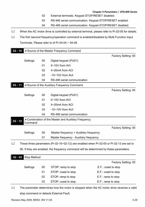
Chapter 5 Parameters|VFD-BW Series
Revision May 2009, BWE0, SW V1.05 5-39
02 External terminals. Keypad STOP/RESET disabled.
03 RS-485 serial communication. Keypad STOP/RESET enabled.
04 RS-485 serial communication. Keypad STOP/RESET disabled.
When the AC motor drive is controlled by external terminal, please refer to Pr.02-05 for details.
The first /second frequency/operation command is enabled/disabled by Multi Function Input
Terminals. Please refer to of Pr.04-04 ~ 04-09.
02 - 10 Source of the Master Frequency Command
Factory Setting: 00
Settings 00 Digital keypad (PU01)
01 0~10V from AVI
02 4~20mA from ACI
03 -10~10V from AUI
04 RS-485 serial communication
02 - 11 Source of the Auxiliary Frequency Command
Factory Setting: 00
Settings 00 Digital keypad (PU01)
01 0~10V from AVI
02 4~20mA from ACI
03 -10~10V from AUI
04 RS-485 serial communication
02 - 12 Combination of the Master and Auxiliary Frequency Command
Factory Setting: 00
Settings 00 Master frequency + Auxiliary frequency
01 Master frequency - Auxiliary frequency
These three parameters (Pr.02-10~02-12) are enabled when Pr.02-00 or Pr.02-13 are set to
06. If they are enabled, the frequency command will be determined by these parameters.
02 - 02 Stop Method
Factory Setting: 00
Settings 00 STOP: ramp to stop E.F.: coast to stop
01 STOP: coast to stop E.F.: coast to stop
02 STOP: ramp to stop E.F.: ramp to stop
03 STOP: coast to stop E.F.: ramp to stop
The parameter determines how the motor is stopped when the AC motor drive receives a valid
stop command or detects External Fault.
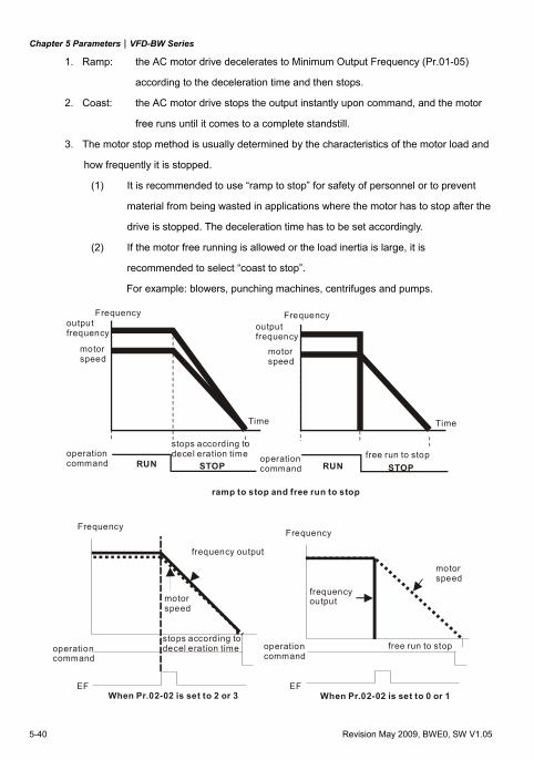
Chapter 5 Parameters|VFD-BW Series
5-40 Revision May 2009, BWE0, SW V1.05
1. Ramp: the AC motor drive decelerates to Minimum Output Frequency (Pr.01-05)
according to the deceleration time and then stops.
2. Coast: the AC motor drive stops the output instantly upon command, and the motor
free runs until it comes to a complete standstill.
3. The motor stop method is usually determined by the characteristics of the motor load and
how frequently it is stopped.
(1) It is recommended to use “ramp to stop” for safety of personnel or to prevent
material from being wasted in applications where the motor has to stop after the
drive is stopped. The deceleration time has to be set accordingly.
(2) If the motor free running is allowed or the load inertia is large, it is
recommended to select “coast to stop”.
For example: blowers, punching machines, centrifuges and pumps.
RUN STOP RUN STOP
Frequency Frequency
TimeTime
outputfrequency
outputfrequency
motorspeed
motorspeed
operationcommand
operationcommand
stops according to decel eration time free run to stop
ramp to stop and free run to stop
EF
FrequencyFrequency
frequency output
motorspeed
EF
operationcommand
stops according to decel eration time
When Pr.02-02 is set to 2 or 3
frequency output
free run to stopoperationcommand
When Pr.02-02 is set to 0 or 1
motorspeed
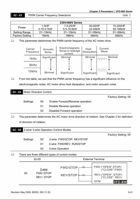
Chapter 5 Parameters|VFD-BW Series
Revision May 2009, BWE0, SW V1.05 5-41
02 - 03 PWM Carrier Frequency Selections Unit: 1
230V/460V Series
Power 1-5HP 0.75-3.7kW
7.5-25HP 5.5-18.5kW
30-60HP 22-45kW
75-250HP 55-185kW
Setting Range 01~15kHz 01~15kHz 01~09kHz 01~06kHz Factory Setting 15kHz 09kHz 06kHz 06kHz
This parameter determines the PWM carrier frequency of the AC motor drive.
1kHz
8kHz
15kHz
CarrierFrequency
Acoustic Noise
ElectromagneticNoise or leakage current
HeatDissipation
Current Wave
Significant
MinimalSignificant
Minimal
Minimal
Significant
Minimal
Significant From the table, we see that the PWM carrier frequency has a significant influence on the
electromagnetic noise, AC motor drive heat dissipation, and motor acoustic noise.
02 - 04 Motor Direction Control
Factory Setting: 00
Settings 00 Enable Forward/Reverse operation
01 Disable Reverse operation
02 Disabled Forward operation
The parameter determines the AC motor drive direction of rotation. See Chapter 2 for definition
of direction of rotation.
02 - 05 2-wire/ 3-wire Operation Control Modes
Factory Setting: 00
Settings 00 2-wire: FWD/STOP, REV/STOP
01 2-wire: FWD/REV, RUN/STOP
02 3-wire Operation
There are three different types of control modes:
02-05 External Terminal
00 2-wire
FWD /STOP REV / STOP
VFD-BW
FWD:("OPEN":STOP)("CLOSE":FWD)
REV:("OPEN": STOP)("CLOSE": REV)
DCM
FWD/STOP
REV/STOP
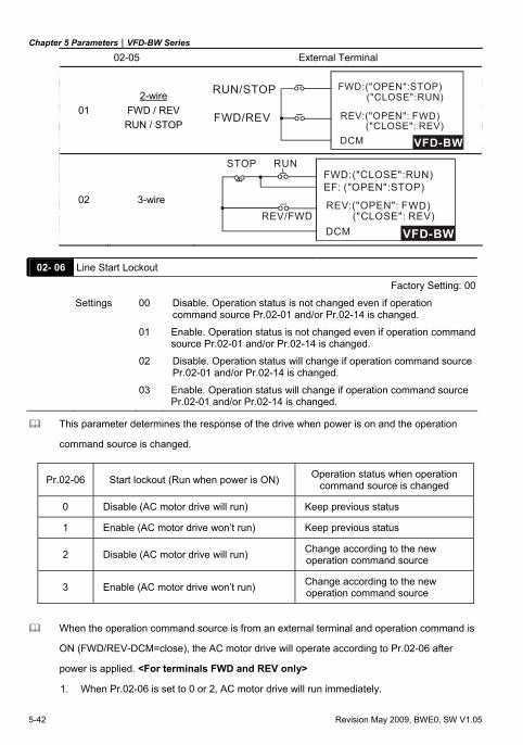
Chapter 5 Parameters|VFD-BW Series
5-42 Revision May 2009, BWE0, SW V1.05
02-05 External Terminal
01 2-wire
FWD / REV RUN / STOP
VFD-BW
FWD:("OPEN":STOP)("CLOSE":RUN)
REV:("OPEN": F("CLOSE": REV)
DCM
RUN/STOP
FWD/REV WD)
02 3-wire
VFD-BW
FWD:("CLOSE":RUN)EF: ("OPEN":STOP)
REV:("OPEN": F("CLOSE": REV)
DCM
STOP RUN
REV/FWDWD)
02- 06 Line Start Lockout
Factory Setting: 00
Settings 00 Disable. Operation status is not changed even if operation command source Pr.02-01 and/or Pr.02-14 is changed.
01 Enable. Operation status is not changed even if operation command source Pr.02-01 and/or Pr.02-14 is changed.
02 Disable. Operation status will change if operation command source Pr.02-01 and/or Pr.02-14 is changed.
03 Enable. Operation status will change if operation command source Pr.02-01 and/or Pr.02-14 is changed.
This parameter determines the response of the drive when power is on and the operation
command source is changed.
Pr.02-06 Start lockout (Run when power is ON) Operation status when operation command source is changed
0 Disable (AC motor drive will run) Keep previous status
1 Enable (AC motor drive won’t run) Keep previous status
2 Disable (AC motor drive will run) Change according to the new operation command source
3 Enable (AC motor drive won’t run) Change according to the new operation command source
When the operation command source is from an external terminal and operation command is
ON (FWD/REV-DCM=close), the AC motor drive will operate according to Pr.02-06 after
power is applied. <For terminals FWD and REV only>
1. When Pr.02-06 is set to 0 or 2, AC motor drive will run immediately.
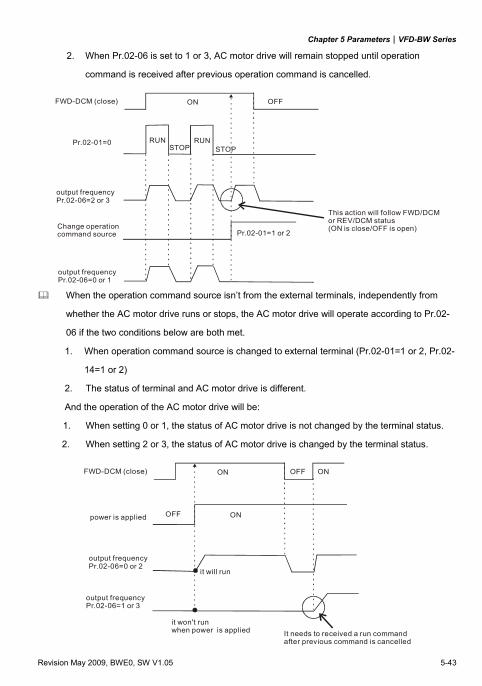
Chapter 5 Parameters|VFD-BW Series
Revision May 2009, BWE0, SW V1.05 5-43
2. When Pr.02-06 is set to 1 or 3, AC motor drive will remain stopped until operation
command is received after previous operation command is cancelled.
RUN RUNSTOP STOP
Pr.02-01=1 or 2
This action will follow FWD/DCMor REV/DCM status (ON is close/OFF is open)
ON OFFFWD-DCM (close)
Pr.02-01=0
output frequencyPr.02-06=2 or 3
Change operation command source
output frequencyPr.02-06=0 or 1
When the operation command source isn’t from the external terminals, independently from
whether the AC motor drive runs or stops, the AC motor drive will operate according to Pr.02-
06 if the two conditions below are both met.
1. When operation command source is changed to external terminal (Pr.02-01=1 or 2, Pr.02-
14=1 or 2)
2. The status of terminal and AC motor drive is different.
And the operation of the AC motor drive will be:
1. When setting 0 or 1, the status of AC motor drive is not changed by the terminal status.
2. When setting 2 or 3, the status of AC motor drive is changed by the terminal status.
It needs to received a run commandafter previous command is cancelled
ON OFFFWD-DCM (close)
power is applied
output frequencyPr.02-06=0 or 2
output frequencyPr.02-06=1 or 3
ON
OFF ON
it will run
it won't runwhen power is applied
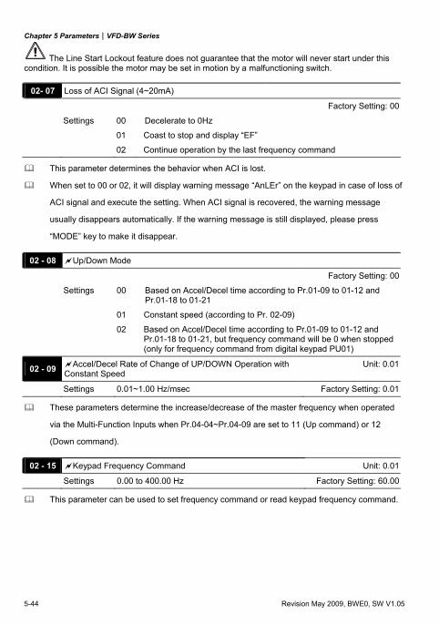
Chapter 5 Parameters|VFD-BW Series
5-44 Revision May 2009, BWE0, SW V1.05
The Line Start Lockout feature does not guarantee that the motor will never start under this condition. It is possible the motor may be set in motion by a malfunctioning switch.
02- 07 Loss of ACI Signal (4~20mA)
Factory Setting: 00
Settings 00 Decelerate to 0Hz
01 Coast to stop and display “EF”
02 Continue operation by the last frequency command
This parameter determines the behavior when ACI is lost.
When set to 00 or 02, it will display warning message “AnLEr” on the keypad in case of loss of
ACI signal and execute the setting. When ACI signal is recovered, the warning message
usually disappears automatically. If the warning message is still displayed, please press
“MODE” key to make it disappear.
02 - 08 Up/Down Mode
Factory Setting: 00
Settings 00 Based on Accel/Decel time according to Pr.01-09 to 01-12 and Pr.01-18 to 01-21
01 Constant speed (according to Pr. 02-09)
02 Based on Accel/Decel time according to Pr.01-09 to 01-12 and Pr.01-18 to 01-21, but frequency command will be 0 when stopped (only for frequency command from digital keypad PU01)
02 - 09 Accel/Decel Rate of Change of UP/DOWN Operation with Constant Speed
Unit: 0.01
Settings 0.01~1.00 Hz/msec Factory Setting: 0.01
These parameters determine the increase/decrease of the master frequency when operated
via the Multi-Function Inputs when Pr.04-04~Pr.04-09 are set to 11 (Up command) or 12
(Down command).
02 - 15 Keypad Frequency Command Unit: 0.01
Settings 0.00 to 400.00 Hz Factory Setting: 60.00
This parameter can be used to set frequency command or read keypad frequency command.
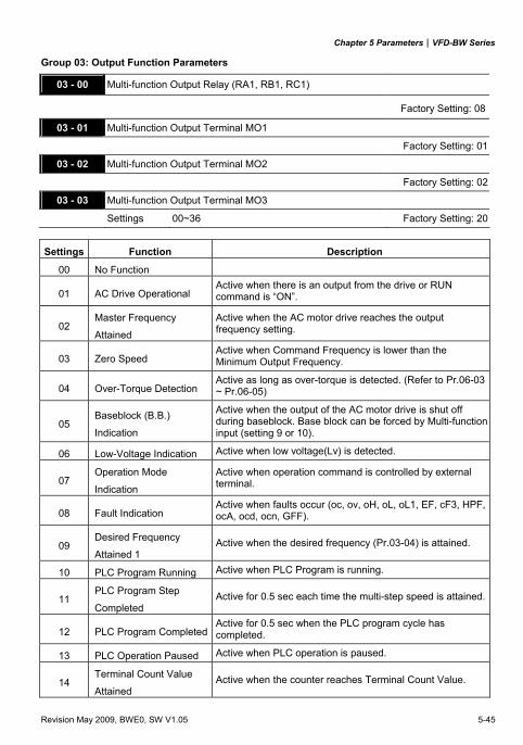
Chapter 5 Parameters|VFD-BW Series
Revision May 2009, BWE0, SW V1.05 5-45
Group 03: Output Function Parameters
03 - 00 Multi-function Output Relay (RA1, RB1, RC1)
Factory Setting: 08
03 - 01 Multi-function Output Terminal MO1 Factory Setting: 01
03 - 02 Multi-function Output Terminal MO2
Factory Setting: 02
03 - 03 Multi-function Output Terminal MO3
Settings 00~36 Factory Setting: 20
Settings Function Description
00 No Function
01 AC Drive Operational Active when there is an output from the drive or RUN command is “ON”.
02 Master Frequency
Attained
Active when the AC motor drive reaches the output frequency setting.
03 Zero Speed Active when Command Frequency is lower than the Minimum Output Frequency.
04 Over-Torque Detection Active as long as over-torque is detected. (Refer to Pr.06-03 ~ Pr.06-05)
05 Baseblock (B.B.)
Indication
Active when the output of the AC motor drive is shut off during baseblock. Base block can be forced by Multi-function input (setting 9 or 10).
06 Low-Voltage Indication Active when low voltage(Lv) is detected.
07 Operation Mode
Indication
Active when operation command is controlled by external terminal.
08 Fault Indication Active when faults occur (oc, ov, oH, oL, oL1, EF, cF3, HPF, ocA, ocd, ocn, GFF).
09 Desired Frequency
Attained 1 Active when the desired frequency (Pr.03-04) is attained.
10 PLC Program Running Active when PLC Program is running.
11 PLC Program Step
Completed Active for 0.5 sec each time the multi-step speed is attained.
12 PLC Program CompletedActive for 0.5 sec when the PLC program cycle has completed.
13 PLC Operation Paused Active when PLC operation is paused.
14 Terminal Count Value
Attained Active when the counter reaches Terminal Count Value.
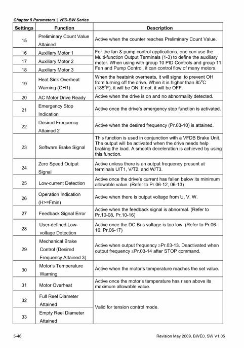
Chapter 5 Parameters|VFD-BW Series
5-46 Revision May 2009, BWE0, SW V1.05
Settings Function Description
15 Preliminary Count Value
Attained Active when the counter reaches Preliminary Count Value.
16 Auxiliary Motor 1
17 Auxiliary Motor 2
18 Auxiliary Motor 3
For the fan & pump control applications, one can use the Multi-function Output Terminals (1-3) to define the auxiliary motor. When using with group 10 PID Controls and group 11 Fan and Pump Control, it can control flow of many motors.
19 Heat Sink Overheat
Warning (OH1)
When the heatsink overheats, it will signal to prevent OH from turning off the drive. When it is higher than 85oC (185oF), it will be ON. If not, it will be OFF.
20 AC Motor Drive Ready Active when the drive is on and no abnormality detected.
21 Emergency Stop
Indication Active once the drive’s emergency stop function is activated.
22 Desired Frequency
Attained 2 Active when the desired frequency (Pr.03-10) is attained.
23 Software Brake Signal
This function is used in conjunction with a VFDB Brake Unit. The output will be activated when the drive needs help braking the load. A smooth deceleration is achieved by using this function.
24 Zero Speed Output
Signal
Active unless there is an output frequency present at terminals U/T1, V/T2, and W/T3.
25 Low-current Detection Active once the drive’s current has fallen below its minimum allowable value. (Refer to Pr.06-12, 06-13)
26 Operation Indication
(H>=Fmin) Active when there is output voltage from U, V, W.
27 Feedback Signal Error Active when the feedback signal is abnormal. (Refer to Pr.10-08, Pr.10-16)
28 User-defined Low-
voltage Detection
Active once the DC Bus voltage is too low. (Refer to Pr.06-16, Pr.06-17)
29
Mechanical Brake
Control (Desired
Frequency Attained 3)
Active when output frequency ≥Pr.03-13. Deactivated when output frequency ≤Pr.03-14 after STOP command.
30 Motor’s Temperature
Warning Active when the motor’s temperature reaches the set value.
31 Motor Overheat Active once the motor’s temperature has risen above its maximum allowable value.
32 Full Reel Diameter
Attained
33 Empty Reel Diameter
Attained
Valid for tension control mode.
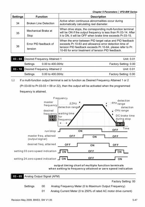
Chapter 5 Parameters|VFD-BW Series
Revision May 2009, BWE0, SW V1.05 5-47
Settings Function Description
34 Broken Line Detection Active when continuous abnormalities occur during automatically calculating reel diameter.
35 Mechanical Brake at
Stop
When drive stops, the corresponding multi-function terminal will be ON if the output frequency is less than Pr.03-14. After it is ON, it will be OFF when brake time exceeds Pr.03-15.
36 Error PID feedback of
tension
When the error between PID target value and PID feedback exceeds Pr.10-63 and allowance error detection time of tension PID feedback exceeds Pr.10-64, please refer to Pr. 10-65 for error treatment of tension PID feedback.
03 - 04 Desired Frequency Attained 1 Unit: 0.01
Settings 0.00 to 400.00Hz Factory Setting: 0.00
03 - 10 Desired Frequency Attained 2 Unit: 0.01
Settings 0.00 to 400.00Hz Factory Setting: 0.00
If a multi-function output terminal is set to function as Desired Frequency Attained 1 or 2
(Pr.03-00 to Pr.03-03 = 09 or 22), then the output will be activated when the programmed
frequency is attained.
-2Hz
4Hz2Hz
OFF
OFF
ON
ON
OFF
ON
OFF ON OFF
OFF ON OFF
ON
ON
detec ti on range
Frequencymasterfrequency
desiredfrequency
detec ti on range detec ti on range
DC brake timeduring stop
Time
waiting t imefor frequency
run/stop
master freq. attained(output signal)
desired freq. attai ned
setting 03 z ero speed indication
sett ing 24 zero speed indication
output t iming chart of multiple function terminals when setting to frequency attained or zero speed indication
03 - 05 Analog Output Signal (AFM)
Factory Setting: 00
Settings 00 Analog Frequency Meter (0 to Maximum Output Frequency)
01 Analog Current Meter (0 to 250% of rated AC motor drive current)
Chapter 5 Parameters|VFD-BW Series
5-48 Revision May 2009, BWE0, SW V1.05
02 Output voltage (0 to Pr.01-02)
03 Output frequency command (0 to Maximum Frequency)
04 Output motor speed (0 to the Maximum Frequency)
05 Load power factor (cos90o to 0o)
This parameter sets the function of the AFM output 0~+10VDC (ACM is common).
03 - 06 Analog Output Gain Unit: 1
Settings 01 to 200% Factory Setting: 100
This parameter sets the voltage range of the analog output signal.
When Pr.03-05 is set to 0, the analog output voltage is directly proportional to the output
frequency of the AC motor drive. With Pr.03-06 set to 100%, the Maximum Output Frequency
(Pr.01-00) of the AC motor drive corresponds to +10VDC on the AFM output.
Similarly, if Pr.03-05 is set to 1, the analog output voltage is directly proportional to the output
current of the AC drive. With Pr.03-06 set to 100%, then 2.5 times the rated current
corresponds to +10VDC on the AFM output.
NOTE
Any type of voltmeter can be used. If the meter reads full scale at a voltage less than 10 volts,
the parameter 03-06 should be set using the following formula:
Pr. 03-06 = ((meter full scale voltage)/10) x 100%
For Example: When using the meter with full scale of 5 volts, adjust Pr.03-06 to 50%. If
Pr.03-05 is set to 0, then 5VDC will correspond to Maximum Output Frequency.
03 - 07 Digital Output Multiplying Factor Unit: 0.1
Settings 0.1 to 100.0 times Factory Setting: 1.0
This parameter determines the multiplying factor for the AC drives digital output frequency at
the digital output terminals (DFM-DCM). The pulse frequency is equal to the AC motor drive
output frequency multiplied by Pr.03-07. (Pulse frequency = actual output frequency x Pr.03-07)
03 - 08 Terminal Count Value Unit: 1
Settings 00 to 65500 Factory Setting: 00
This parameter sets the count value of the internal counter. The external terminal TRG
increases the internal counter. Upon completion of counting, the specified output terminal will
be activated. (Pr.03-00 to Pr.03-03 set to 14).
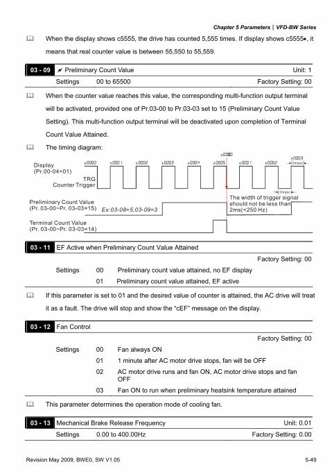
Chapter 5 Parameters|VFD-BW Series
Revision May 2009, BWE0, SW V1.05 5-49
When the display shows c5555, the drive has counted 5,555 times. If display shows c5555•, it
means that real counter value is between 55,550 to 55,559.
03 - 09 Preliminary Count Value Unit: 1
Settings 00 to 65500 Factory Setting: 00
When the counter value reaches this value, the corresponding multi-function output terminal
will be activated, provided one of Pr.03-00 to Pr.03-03 set to 15 (Preliminary Count Value
Setting). This multi-function output terminal will be deactivated upon completion of Terminal
Count Value Attained.
The timing diagram:
Terminal Count Value(Pr. 03-00~Pr. 03-03=14)
Preliminary Count Value(Pr. 03-00~Pr. 03-03=15)
Display(Pr.00-04=01)
TRGCounter Trigger
The width of trigger signalshould not be less than2ms(<250 Hz)
2msec
2msec
Ex:03-08=5,03-09=3
03 - 11 EF Active when Preliminary Count Value Attained
Factory Setting: 00
Settings 00 Preliminary count value attained, no EF display
01 Preliminary count value attained, EF active
If this parameter is set to 01 and the desired value of counter is attained, the AC drive will treat
it as a fault. The drive will stop and show the “cEF” message on the display.
03 - 12 Fan Control
Factory Setting: 00
Settings 00 Fan always ON
01 1 minute after AC motor drive stops, fan will be OFF
02 AC motor drive runs and fan ON, AC motor drive stops and fan OFF
03 Fan ON to run when preliminary heatsink temperature attained
This parameter determines the operation mode of cooling fan.
03 - 13 Mechanical Brake Release Frequency Unit: 0.01
Settings 0.00 to 400.00Hz Factory Setting: 0.00
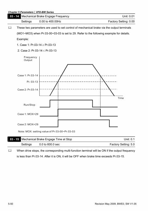
Chapter 5 Parameters|VFD-BW Series
5-50 Revision May 2009, BWE0, SW V1.05
03 - 14 Mechanical Brake Engage Frequency Unit: 0.01
Settings 0.00 to 400.00Hz Factory Setting: 0.00
These two parameters are used to set control of mechanical brake via the output terminals
(MO1~MO3) when Pr.03-00~03-03 is set to 29. Refer to the following example for details.
Example:
1. Case 1: Pr.03-14 ≥ Pr.03-13
2. Case 2: Pr.03-14 ≤ Pr.03-13
Case 1: Pr.03-14
Case 2: Pr.03-14
Pr. 03-13
FrequencyOutput
Time
Run/Stop
Case 1: MOX=29
Case 2: MOX=29
Note: MOX: setting value of Pr.03-00~Pr.03-03
03 - 15 Mechanical Brake Engage Time at Stop Unit: 0.1
Settings 0.0 to 600.0 sec Factory Setting: 5.0
When drive stops, the corresponding multi-function terminal will be ON if the output frequency
is less than Pr.03-14. After it is ON, it will be OFF when brake time exceeds Pr.03-15.
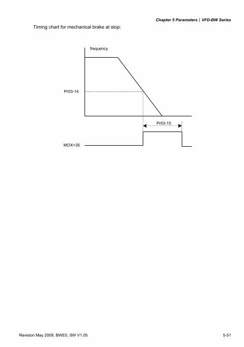
Chapter 5 Parameters|VFD-BW Series
Revision May 2009, BWE0, SW V1.05 5-51
Timing chart for mechanical brake at stop:
Pr03-14
MOX=35
Pr03-15
frequency
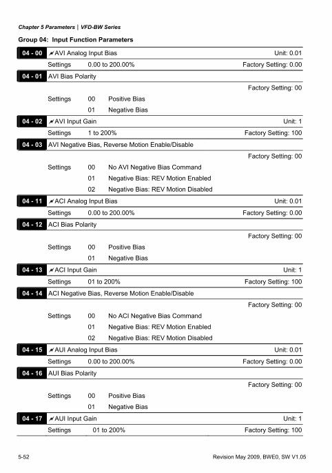
Chapter 5 Parameters|VFD-BW Series
5-52 Revision May 2009, BWE0, SW V1.05
Group 04: Input Function Parameters
04 - 00 AVI Analog Input Bias Unit: 0.01
Settings 0.00 to 200.00% Factory Setting: 0.00
04 - 01 AVI Bias Polarity
Factory Setting: 00
Settings 00 Positive Bias
01 Negative Bias
04 - 02 AVI Input Gain Unit: 1
Settings 1 to 200% Factory Setting: 100
04 - 03 AVI Negative Bias, Reverse Motion Enable/Disable
Factory Setting: 00
Settings 00 No AVI Negative Bias Command
01 Negative Bias: REV Motion Enabled
02 Negative Bias: REV Motion Disabled
04 - 11 ACI Analog Input Bias Unit: 0.01
Settings 0.00 to 200.00% Factory Setting: 0.00
04 - 12 ACI Bias Polarity
Factory Setting: 00
Settings 00 Positive Bias
01 Negative Bias
04 - 13 ACI Input Gain Unit: 1
Settings 01 to 200% Factory Setting: 100
04 - 14 ACI Negative Bias, Reverse Motion Enable/Disable
Factory Setting: 00
Settings 00 No ACI Negative Bias Command
01 Negative Bias: REV Motion Enabled
02 Negative Bias: REV Motion Disabled
04 - 15 AUI Analog Input Bias Unit: 0.01
Settings 0.00 to 200.00% Factory Setting: 0.00
04 - 16 AUI Bias Polarity
Factory Setting: 00
Settings 00 Positive Bias
01 Negative Bias
04 - 17 AUI Input Gain Unit: 1
Settings 01 to 200% Factory Setting: 100
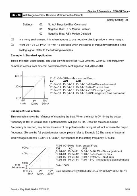
Chapter 5 Parameters|VFD-BW Series
Revision May 2009, BWE0, SW V1.05 5-53
04 - 18 AUI Negative Bias, Reverse Motion Enable/Disable
Factory Setting: 00
Settings 00 No AUI Negative Bias Command
01 Negative Bias: REV Motion Enabled
02 Negative Bias: REV Motion Disabled
In a noisy environment, it is advantageous to use negative bias to provide a noise margin.
Pr.04-00 ~ 04-03, Pr.04-11 ~ 04-18 are used when the source of frequency command is the
analog signal. Refer to the following examples.
Example 1: Standard application
This is the most used setting. The user only needs to set Pr.02-00 to 01, 02 or 03. The frequency
command comes from external potentiometer/current signal on AVI, ACI or AUI.
60Hz
0Hz 0V4mA
5V12mA
10V20mA
Pr.01-00=60Hz--Max. output Freq.AVI ACI AUIPr.04-00 Pr.04-11 Pr.04-15=0%--Bias adjustmentPr.04-01 Pr.04-12 Pr.04-16=0--Positive biasPr.04-02 Pr.04-13 Pr.04-17=100%--Input gainPr.04-03 Pr.04-14 Pr.04-18=0No negative bias command
30Hz
Example 2: Use of bias
This example shows the influence of changing the bias. When the input is 0V (4mA) the output
frequency is 10 Hz. At mid-point a potentiometer will give 40 Hz. Once the Maximum Output
Frequency is reached, any further increase of the potentiometer or signal will not increase the output
frequency. (To use the full potentiometer range, please refer to Example 3.) The value of external
input voltage/current 0-8.33V (4-17.33mA) corresponds to the setting frequency 10-60Hz.
60Hz
0Hz 0V4mA
5V12mA
10V20mA
Pr.01-00=60Hz--Max. output Freq.AVI ACI AUIPr.04-00 Pr.04-11 Pr.04-15=16.7%--Bias adjustmentPr.04-01 Pr.04-12 Pr.04-16=0--Positive biasPr.04-02 Pr.04-13 Pr.04-17=100%--Input gainPr.04-03 Pr.04-14 Pr.04-18=0--No negative bias command
Gain:100%
Bias adjustment:((10Hz/60Hz)/(Gain/100%))*100%=16.7%
10Hz BiasAdjustment
40Hz
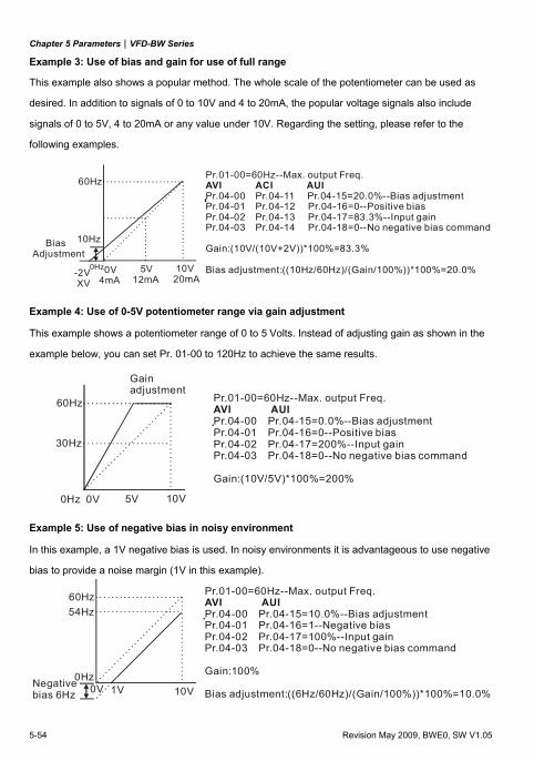
Chapter 5 Parameters|VFD-BW Series
5-54 Revision May 2009, BWE0, SW V1.05
Example 3: Use of bias and gain for use of full range
This example also shows a popular method. The whole scale of the potentiometer can be used as
desired. In addition to signals of 0 to 10V and 4 to 20mA, the popular voltage signals also include
signals of 0 to 5V, 4 to 20mA or any value under 10V. Regarding the setting, please refer to the
following examples.
60Hz
0Hz 0V4mA
5V12mA
10V20mA
Pr.01-00=60Hz--Max. output Freq.AVI ACI AUIPr.04-00 Pr.04-11 Pr.04-15=20.0%--Bias adjustmentPr.04-01 Pr.04-12 Pr.04-16=0--Positive biasPr.04-02 Pr.04-13 Pr.04-17=83.3%--Input gainPr.04-03 Pr.04-14 Pr.04-18=0--No negative bias command
Gain:(10V/(10V+2V))*100%=83.3%
Bias adjustment:((10Hz/60Hz)/(Gain/100%))*100%=20.0%
10Hz BiasAdjustment
-2V XV
Example 4: Use of 0-5V potentiometer range via gain adjustment
This example shows a potentiometer range of 0 to 5 Volts. Instead of adjusting gain as shown in the
example below, you can set Pr. 01-00 to 120Hz to achieve the same results.
Pr.01-00=60Hz--Max. output Freq.AVI AUIPr.04-00 Pr.04-15=0.0%--Bias adjustmentPr.04-01 Pr.04-16=0--Positive biasPr.04-02 Pr.04-17=200%--Input gainPr.04-03 Pr.04-18=0--No negative bias command
Gain:(10V/5V)*100%=200%
60Hz
0Hz 0V 5V
30Hz
Gainadjustment
10V
Example 5: Use of negative bias in noisy environment
In this example, a 1V negative bias is used. In noisy environments it is advantageous to use negative
bias to provide a noise margin (1V in this example).
60Hz
0Hz 0V 10V
Pr.01-00=60Hz--Max. output Freq.AVI AUIPr.04-00 Pr.04-15=10.0%--Bias adjustmentPr.04-01 Pr.04-16=1--Negative biasPr.04-02 Pr.04-17=100%--Input gainPr.04-03 Pr.04-18=0--No negative bias command
Gain:100%
Bias adjustment:((6Hz/60Hz)/(Gain/100%))*100%=10.0%Negativebias 6Hz 1V
54Hz
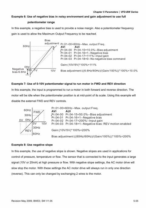
Chapter 5 Parameters|VFD-BW Series
Revision May 2009, BWE0, SW V1.05 5-55
Example 6: Use of negative bias in noisy environment and gain adjustment to use full
potentiometer range
In this example, a negative bias is used to provide a noise margin. Also a potentiometer frequency
gain is used to allow the Maximum Output Frequency to be reached.
60Hz
0Hz 0V 10V
Pr.01-00=60Hz--Max. output Freq.
Negativebias 6.6Hz 1V
Biasadjustment
AVI AUIPr.04-00 Pr.04-15=10.0%--Bias adjustmentPr.04-01 Pr.04-16=1--Negative biasPr.04-02 Pr.04-17=111%--Input gainPr.04-03 Pr.04-18=0--No negative bias command
Gain:(10V/9V)*100%=111%
Bias adjustment:((6.6Hz/60Hz)/(Gain/100%))*100%=10.0%
Example 7: Use of 0-10V potentiometer signal to run motor in FWD and REV direction
In this example, the input is programmed to run a motor in both forward and reverse direction. The
motor will be idle when the potentiometer position is at mid-point of its scale. Using this example will
disable the external FWD and REV controls.
Pr.01-00=60Hz--Max. output Freq.AVI AUIPr.04-00 Pr.04-15=50.0%--Bias adjustmentPr.04-01 Pr.04-16=1--Negative biasPr.04-02 Pr.04-17=200%--Input gainPr.04-03 Pr.04-18=1--Negative bias: REV motion enabled
Gain:(10V/5V)*100%=200%
Bias adjustment:((60Hz/60Hz)/(Gain/100%))*100%=200%
60Hz
30Hz0Hz0V
5V 10V30Hz
60HzREV
FWD
Example 8: Use negative slope
In this example, the use of negative slope is shown. Negative slopes are used in applications for
control of pressure, temperature or flow. The sensor that is connected to the input generates a large
signal (10V or 20mA) at high pressure or flow. With negative slope settings, the AC motor drive will
slow stop the motor. With these settings the AC motor drive will always run in only one direction
(reverse). This can only be changed by exchanging 2 wires to the motor.
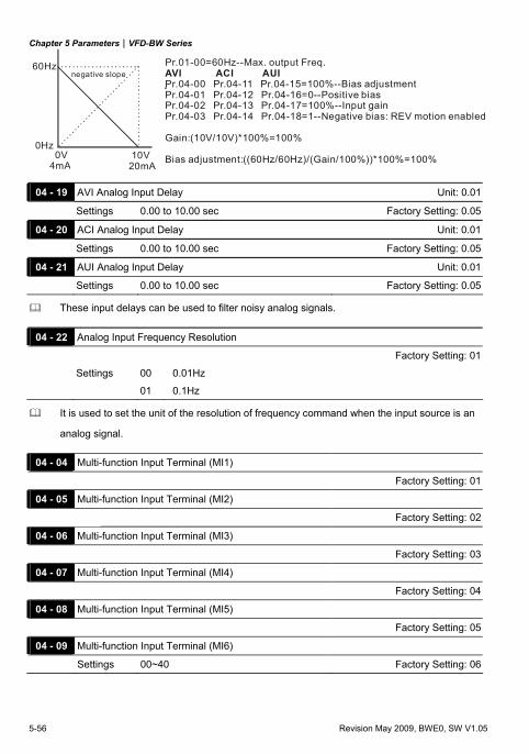
Chapter 5 Parameters|VFD-BW Series
5-56 Revision May 2009, BWE0, SW V1.05
60Hz
0Hz 0V4mA
10V20mA
Pr.01-00=60Hz--Max. output Freq.AVI ACI AUIPr.04-00 Pr.04-11 Pr.04-15=100%--Bias adjustmentPr.04-01 Pr.04-12 Pr.04-16=0--Positive biasPr.04-02 Pr.04-13 Pr.04-17=100%--Input gainPr.04-03 Pr.04-14 Pr.04-18=1--Negative bias: REV motion enabled
Gain:(10V/10V)*100%=100%
Bias adjustment:((60Hz/60Hz)/(Gain/100%))*100%=100%
negative slope
04 - 19 AVI Analog Input Delay Unit: 0.01
Settings 0.00 to 10.00 sec Factory Setting: 0.05
04 - 20 ACI Analog Input Delay Unit: 0.01
Settings 0.00 to 10.00 sec Factory Setting: 0.05
04 - 21 AUI Analog Input Delay Unit: 0.01
Settings 0.00 to 10.00 sec Factory Setting: 0.05
These input delays can be used to filter noisy analog signals.
04 - 22 Analog Input Frequency Resolution
Factory Setting: 01
Settings 00 0.01Hz
01 0.1Hz
It is used to set the unit of the resolution of frequency command when the input source is an
analog signal.
04 - 04 Multi-function Input Terminal (MI1)
Factory Setting: 01
04 - 05 Multi-function Input Terminal (MI2)
Factory Setting: 02
04 - 06 Multi-function Input Terminal (MI3)
Factory Setting: 03
04 - 07 Multi-function Input Terminal (MI4)
Factory Setting: 04
04 - 08 Multi-function Input Terminal (MI5)
Factory Setting: 05
04 - 09 Multi-function Input Terminal (MI6)
Settings 00~40 Factory Setting: 06
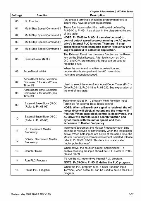
Chapter 5 Parameters|VFD-BW Series
Revision May 2009, BWE0, SW V1.05 5-57
Settings Function Description
00 No Function Any unused terminals should be programmed to 0 to insure they have no effect on operation.
01 Multi-Step Speed Command 1
02 Multi-Step Speed Command 2
03 Multi-Step Speed Command 3
04 Multi-Step Speed Command 4
These four inputs select the multi-speed defined by Pr.05-00 to Pr.05-14 as shown in the diagram at the end of this table. NOTE: Pr.05-00 to Pr.05-14 can also be used to control output speed by programming the AC motor drive’s internal PLC function. There are 17 step speed frequencies (including Master Frequency and Jog Frequency) to select for application.
05 External Reset (N.O.)
The External Reset has the same function as the Reset key on the Digital keypad. After faults such as O.H., O.C. and O.V. are cleared this input can be used to reset the drive.
06 Accel/Decel Inhibit When the command is active, acceleration and deceleration is stopped and the AC motor drive maintains a constant speed.
07 Accel/Decel Time Selection Command 1 for Accel/Decel Time 1/2
08 Accel/Decel Time Selection Command 2 for Accel/Decel Time 3/4
Used to select the one of four Accel/Decel Times (Pr.01-09 to Pr.01-12, Pr.01-18 to Pr.01-21). See explanation at the end of this table.
09 External Base Block (N.O.) (Refer to Pr. 08-06)
10 External Base Block (N.C.) (Refer to Pr. 08-06)
Parameter values 9, 10 program Multi-Function Input Terminals for external Base Block control. NOTE: When a Base-Block signal is received, the AC motor drive will block all output and the motor will free run. When base block control is deactivated, the AC drive will start its speed search function and synchronize with the motor speed, and then accelerate to Master Frequency.
11 UP: Increment Master Frequency
12 DOWN: Decrement Master Frequency
Increment/decrement the Master Frequency each time an input is received or continuously when the input stays active. When both inputs are active at the same time, the Master Frequency increment/decrement is halted. Please refer to Pr.02-08, 02-09. This function is also called “motor potentiometer”.
13 Counter Reset When active, the counter is reset and inhibited. To enable counting the input should be OFF. Refer to Pr.03-08 and 03-09.
14 Run PLC Program To run the AC motor drive internal PLC program. NOTE: Pr.05-00 to Pr.05-16 define the PLC program.
15 Pause PLC Program When the PLC program runs, a Multi-Function Input Terminal, when set to 15, can be used to pause the PLC program.
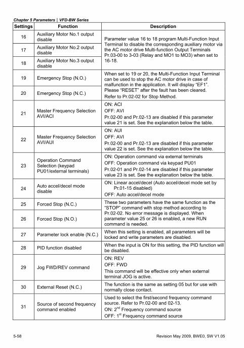
Chapter 5 Parameters|VFD-BW Series
5-58 Revision May 2009, BWE0, SW V1.05
Settings Function Description
16 Auxiliary Motor No.1 output disable
17 Auxiliary Motor No.2 output disable
18 Auxiliary Motor No.3 output disable
Parameter value 16 to 18 program Multi-Function Input Terminal to disable the corresponding auxiliary motor via the AC motor drive Multi-function Output Terminals Pr.03-00 to 3-03 (Relay and MO1 to MO3) when set to 16-18.
19 Emergency Stop (N.O.)
20 Emergency Stop (N.C.)
When set to 19 or 20, the Multi-Function Input Terminal can be used to stop the AC motor drive in case of malfunction in the application. It will display “EF1”. Please “RESET” after the fault has been cleared. Refer to Pr.02-02 for Stop Method.
21 Master Frequency Selection AVI/ACI
ON: ACI OFF: AVI Pr.02-00 and Pr.02-13 are disabled if this parameter value 21 is set. See the explanation below the table.
22 Master Frequency Selection AVI/AUI
ON: AUI OFF: AVI Pr.02-00 and Pr.02-13 are disabled if this parameter value 22 is set. See the explanation below the table.
23 Operation Command Selection (keypad PU01/external terminals)
ON: Operation command via external terminals OFF: Operation command via keypad PU01 Pr.02-01 and Pr.02-14 are disabled if this parameter value 23 is set. See the explanation below the table.
24 Auto accel/decel mode disable
ON: Linear accel/decel (Auto accel/decel mode set by Pr.01-15 disabled)
OFF: Auto accel/decel mode
25 Forced Stop (N.C.)
26 Forced Stop (N.O.)
These two parameters have the same function as the “STOP” command with stop method according to Pr.02-02. No error message is displayed. When parameter value 25 or 26 is enabled, a new RUN command is needed.
27 Parameter lock enable (N.C.) When this setting is enabled, all parameters will be locked and write parameters are disabled.
28 PID function disabled When the input is ON for this setting, the PID function will be disabled.
29 Jog FWD/REV command
ON: REV OFF: FWD This command will be effective only when external terminal JOG is active.
30 External Reset (N.C.) The function is the same as setting 05 but for use with normally close contact.
31 Source of second frequency command enabled
Used to select the first/second frequency command source. Refer to Pr.02-00 and 02-13. ON: 2nd Frequency command source OFF: 1st Frequency command source
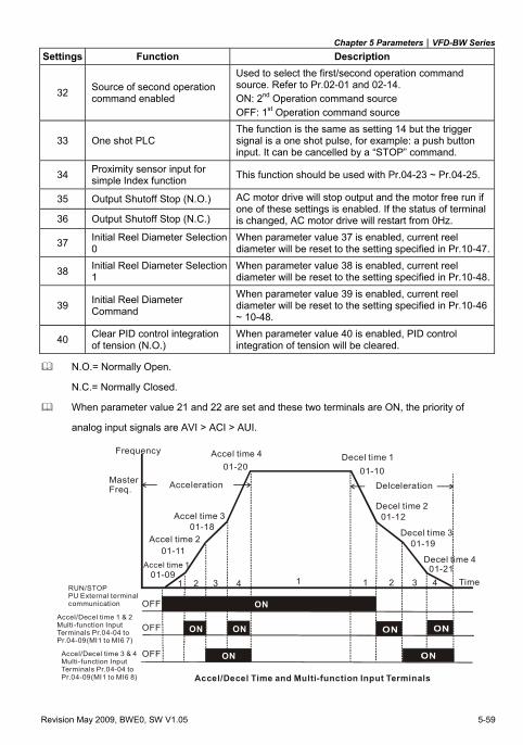
Chapter 5 Parameters|VFD-BW Series
Revision May 2009, BWE0, SW V1.05 5-59
Settings Function Description
32 Source of second operation command enabled
Used to select the first/second operation command source. Refer to Pr.02-01 and 02-14. ON: 2nd Operation command source OFF: 1st Operation command source
33 One shot PLC The function is the same as setting 14 but the trigger signal is a one shot pulse, for example: a push button input. It can be cancelled by a “STOP” command.
34 Proximity sensor input for simple Index function This function should be used with Pr.04-23 ~ Pr.04-25.
35 Output Shutoff Stop (N.O.)
36 Output Shutoff Stop (N.C.)
AC motor drive will stop output and the motor free run if one of these settings is enabled. If the status of terminal is changed, AC motor drive will restart from 0Hz.
37 Initial Reel Diameter Selection 0
When parameter value 37 is enabled, current reel diameter will be reset to the setting specified in Pr.10-47.
38 Initial Reel Diameter Selection 1
When parameter value 38 is enabled, current reel diameter will be reset to the setting specified in Pr.10-48.
39 Initial Reel Diameter Command
When parameter value 39 is enabled, current reel diameter will be reset to the setting specified in Pr.10-46 ~ 10-48.
40 Clear PID control integration of tension (N.O.)
When parameter value 40 is enabled, PID control integration of tension will be cleared.
N.O.= Normally Open.
N.C.= Normally Closed.
When parameter value 21 and 22 are set and these two terminals are ON, the priority of
analog input signals are AVI > ACI > AUI.
Frequency
Time
Acceleration Delceleration
Accel time 1
Accel time 2
Accel time 3
Accel time 4 Decel time 1
Decel time 2
Decel time 3
Decel time 4
01-09
01-11
01-18
01-20 01-10
01-12
01-19
01-21
MasterFreq.
1 12 23 34 4
OFF
OFF
OFF
1
ON
ON
ON
ON
RUN/STOPPU External terminalcommunication
Accel/Decel time 1 & 2Multi-function InputTerminals Pr.04-04 toPr.04-09(MI1 to MI6 7)
Accel/Decel time 3 & 4Multi-function InputTerminals Pr.04-04 toPr.04-09(MI1 to MI6 8) Accel/Decel Time and Multi-function Input Terminals
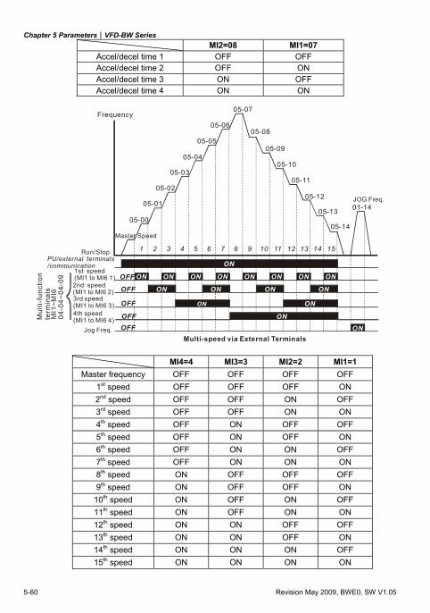
Chapter 5 Parameters|VFD-BW Series
5-60 Revision May 2009, BWE0, SW V1.05
MI2=08 MI1=07 Accel/decel time 1 OFF OFF Accel/decel time 2 OFF ON Accel/decel time 3 ON OFF Accel/decel time 4 ON ON
ON ON ON ON ON ON ON ON
ONONONON
ON
ON
ON
ON
05-00
05-01
05-02
05-03
05-04
05-05
05-06
05-07
05-08
05-09
05-10
05-11
05-12
05-13
05-14
01-14
OFF
OFF
OFF
OFF
OFF
1 2 3 4 5 6 7 8 9 10 11 12 13 14 15
Mul
ti-fu
nctio
nte
rmin
als
MI1
~MI6
04-0
4~04
-09
Frequency
Master Speed
JOG Freq.
2nd speed(MI1 to MI6 2)
1st speed(MI1 to MI6 1)
Jog Freq.Multi-speed via External Terminals
Run/StopPU/external terminals/communication
3rd speed(MI1 to MI6 3)4th speed(MI1 to MI6 4)
MI4=4 MI3=3 MI2=2 MI1=1 Master frequency OFF OFF OFF OFF
1st speed OFF OFF OFF ON 2nd speed OFF OFF ON OFF 3rd speed OFF OFF ON ON 4th speed OFF ON OFF OFF 5th speed OFF ON OFF ON 6th speed OFF ON ON OFF 7th speed OFF ON ON ON 8th speed ON OFF OFF OFF 9th speed ON OFF OFF ON
10th speed ON OFF ON OFF 11th speed ON OFF ON ON 12th speed ON ON OFF OFF 13th speed ON ON OFF ON 14th speed ON ON ON OFF 15th speed ON ON ON ON
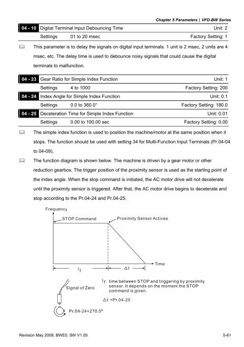
Chapter 5 Parameters|VFD-BW Series
Revision May 2009, BWE0, SW V1.05 5-61
This parameter is to delay the signals on digital input terminals. 1 unit is 2 msec, 2 units are 4
msec, etc. The delay time is used to debounce noisy signals that could cause the digital
terminals to malfunction.
04 - 23 Gear Ratio for Simple Index Function Unit: 1
Settings 4 to 1000 Factory Setting: 200
04 - 24 Index Angle for Simple Index Function Unit: 0.1
Settings 0.0 to 360.0° Factory Setting: 180.0
04 - 25 Deceleration Time for Simple Index Function Unit: 0.01
Settings 0.00 to 100.00 sec Factory Setting: 0.00
The simple index function is used to position the machine/motor at the same position when it
stops. The function should be used with setting 34 for Multi-Function Input Terminals (Pr.04-04
to 04-09).
The function diagram is shown below. The machine is driven by a gear motor or other
reduction gearbox. The trigger position of the proximity sensor is used as the starting point of
the index angle. When the stop command is initiated, the AC motor drive will not decelerate
until the proximity sensor is triggered. After that, the AC motor drive begins to decelerate and
stop according to the Pr.04-24 and Pr.04-25.
time between STOP and triggering by proximity sensor. It depends on the moment the STOP command is given.
Frequency
Proximity Sensor Actives
Time
Signal of Zero
=Pr.04-25
STOP Command
:
04 - 10 Digital Terminal Input Debouncing Time Unit: 2
Settings 01 to 20 msec Factory Setting: 1
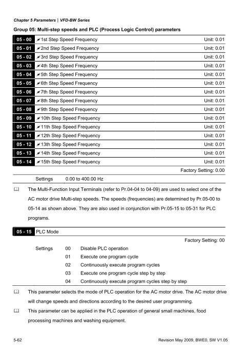
Chapter 5 Parameters|VFD-BW Series
5-62 Revision May 2009, BWE0, SW V1.05
Group 05: Multi-step speeds and PLC (Process Logic Control) parameters
05 - 00 1st Step Speed Frequency Unit: 0.01
05 - 01 2nd Step Speed Frequency Unit: 0.01
05 - 02 3rd Step Speed Frequency Unit: 0.01
05 - 03 4th Step Speed Frequency Unit: 0.01
05 - 04 5th Step Speed Frequency Unit: 0.01
05 - 05 6th Step Speed Frequency Unit: 0.01
05 - 06 7th Step Speed Frequency Unit: 0.01
05 - 07 8th Step Speed Frequency Unit: 0.01
05 - 08 9th Step Speed Frequency Unit: 0.01
05 - 09 10th Step Speed Frequency Unit: 0.01
05 - 10 11th Step Speed Frequency Unit: 0.01
05 - 11 12th Step Speed Frequency Unit: 0.01
05 - 12 13th Step Speed Frequency Unit: 0.01
05 - 13 14th Step Speed Frequency Unit: 0.01
05 - 14 15th Step Speed Frequency Unit: 0.01
Factory Setting: 0.00
Settings 0.00 to 400.00 Hz
The Multi-Function Input Terminals (refer to Pr.04-04 to 04-09) are used to select one of the
AC motor drive Multi-step speeds. The speeds (frequencies) are determined by Pr.05-00 to
05-14 as shown above. They are also used in conjunction with Pr.05-15 to 05-31 for PLC
programs.
05 - 15 PLC Mode
Factory Setting: 00
Settings 00 Disable PLC operation
01 Execute one program cycle
02 Continuously execute program cycles
03 Execute one program cycle step by step
04 Continuously execute program cycles step by step
This parameter selects the mode of PLC operation for the AC motor drive. The AC motor drive
will change speeds and directions according to the desired user programming.
This parameter can be applied in the PLC operation of general small machines, food
processing machines and washing equipment.
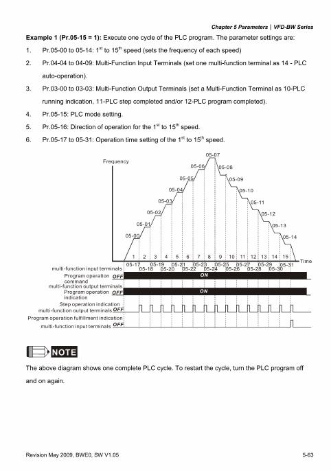
Chapter 5 Parameters|VFD-BW Series
Revision May 2009, BWE0, SW V1.05 5-63
Example 1 (Pr.05-15 = 1): Execute one cycle of the PLC program. The parameter settings are:
1. Pr.05-00 to 05-14: 1st to 15th speed (sets the frequency of each speed)
2. Pr.04-04 to 04-09: Multi-Function Input Terminals (set one multi-function terminal as 14 - PLC
auto-operation).
3. Pr.03-00 to 03-03: Multi-Function Output Terminals (set a Multi-Function Terminal as 10-PLC
running indication, 11-PLC step completed and/or 12-PLC program completed).
4. Pr.05-15: PLC mode setting.
5. Pr.05-16: Direction of operation for the 1st to 15th speed.
6. Pr.05-17 to 05-31: Operation time setting of the 1st to 15th speed.
ON
05-00
05-01
05-02
05-03
05-04
05-05
05-06
05-07
05-08
05-09
05-10
05-11
05-12
05-13
05-14
OFF
OFF
1 2 3 4 5 6 7 8 9 10 11 12 13 14 15
ONOFF
OFF
05-1705-18
05-1905-20
05-2105-22
05-2305-24
05-2505-26
05-2705-28
05-2905-30
05-31
Frequency
Time
Program operationcommand
Program operationindication
Step operation indication
Program operation fulfillment indication
multi-function input terminals
multi-function output terminals
multi-function output terminals
multi-function input terminals
NOTE
The above diagram shows one complete PLC cycle. To restart the cycle, turn the PLC program off
and on again.
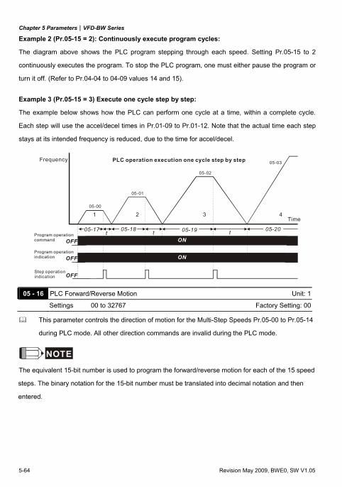
Chapter 5 Parameters|VFD-BW Series
5-64 Revision May 2009, BWE0, SW V1.05
Example 2 (Pr.05-15 = 2): Continuously execute program cycles:
The diagram above shows the PLC program stepping through each speed. Setting Pr.05-15 to 2
continuously executes the program. To stop the PLC program, one must either pause the program or
turn it off. (Refer to Pr.04-04 to 04-09 values 14 and 15).
Example 3 (Pr.05-15 = 3) Execute one cycle step by step:
The example below shows how the PLC can perform one cycle at a time, within a complete cycle.
Each step will use the accel/decel times in Pr.01-09 to Pr.01-12. Note that the actual time each step
stays at its intended frequency is reduced, due to the time for accel/decel.
ON ON ON
ON
OFF
1 2 3 4
ONOFF
OFFttt05-17 05-18 05-19 05-20
05-00
05-01
05-02
05-03Frequency
Time
Program operationcommand
Program operationindication
Step operation indication
PLC operation execution one cycle step by step
05 - 16 PLC Forward/Reverse Motion Unit: 1
Settings 00 to 32767 Factory Setting: 00
This parameter controls the direction of motion for the Multi-Step Speeds Pr.05-00 to Pr.05-14
during PLC mode. All other direction commands are invalid during the PLC mode.
NOTE
The equivalent 15-bit number is used to program the forward/reverse motion for each of the 15 speed
steps. The binary notation for the 15-bit number must be translated into decimal notation and then
entered.
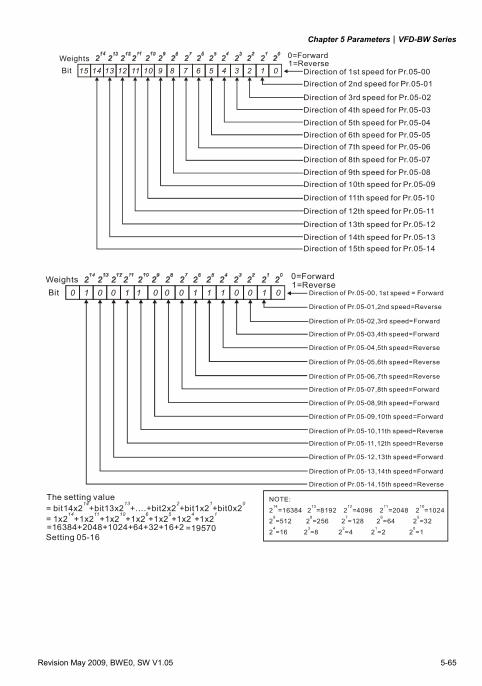
Chapter 5 Parameters|VFD-BW Series
Revision May 2009, BWE0, SW V1.05 5-65
123456789101112131415 0WeightsBit
0=Forward1=Reverse
Direction of Pr.05-001st speed for Direction of Pr.05-012nd speed for
Direction of Pr.05-023rd speed for Direction of Pr.05-034th speed for
Direction of Pr.05-045th speed for Direction of Pr.05-056th speed for Direction of Pr.05-067th speed for
Direction of Pr.05-078th speed for Direction of Pr.05-089th speed for Direction of Pr.05-0910th speed for
Direction of Pr.05-1011th speed for
Direction of Pr.05-1112th speed for
Direction of 1 Pr.05-123th speed for
Direction of Pr.05-1314th speed for Direction of Pr.05-1415th speed for
100111000110010 0WeightsBit
0=Forward1=Reverse
Direction of Pr.05-00, 1st speed = Forward
Direction of Pr.05-01,2nd speed=Reverse
Direction of ,Pr.05-02 3rd speed=Forward
Direction of ,Pr.05-03 4th speed=Forward
Direction of ,Pr.05-04 5th speed=Reverse
Direction of Pr.05-05,6th speed=Reverse
Direction of Pr.05-06,7th speed=Reverse
Direction of Pr.05-07,8th speed=Forward
Direction of Pr.05-08,9th speed=Forward
Direction of Pr.05-09,10th speed=Forward
Direction of Pr.05-10,11th speed=Reverse
Direction of Pr.05-11,12th speed=Reverse
Direction of 1Pr.05-12, 3th speed=Forward
Direction of Pr.05-13,14th speed=Forward
Direction of Pr.05-14,15th speed=Reverse
The setting value= bit14x2 +
14bit13x2 +....+bit2x2 +bit1x2 +bit0x2
13 2 1 0
= 1x2 +14
1x2 +1x2 +1x2 +1x2 +1x2 +1x211 10 6 5 4 1
=16384+2048+1024+64+32+16+2Setting 05-16
=19570
NOTE:
2 =16384 2 =8192 2 =4096 2 =2048 2 =10242 =512 2 =256 2 =128 2 =64 2 =32
2 =16 2 =8 2 =4 2 =2 2 =1
14 13 12 11 10
9 8 7 6 5
4 3 2 1 0
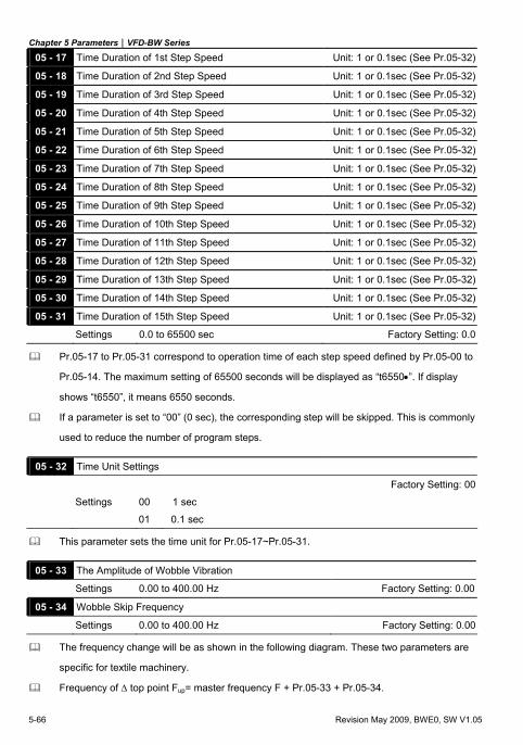
Chapter 5 Parameters|VFD-BW Series
5-66 Revision May 2009, BWE0, SW V1.05
05 - 17 Time Duration of 1st Step Speed Unit: 1 or 0.1sec (See Pr.05-32)
05 - 18 Time Duration of 2nd Step Speed Unit: 1 or 0.1sec (See Pr.05-32)
05 - 19 Time Duration of 3rd Step Speed Unit: 1 or 0.1sec (See Pr.05-32)
05 - 20 Time Duration of 4th Step Speed Unit: 1 or 0.1sec (See Pr.05-32)
05 - 21 Time Duration of 5th Step Speed Unit: 1 or 0.1sec (See Pr.05-32)
05 - 22 Time Duration of 6th Step Speed Unit: 1 or 0.1sec (See Pr.05-32)
05 - 23 Time Duration of 7th Step Speed Unit: 1 or 0.1sec (See Pr.05-32)
05 - 24 Time Duration of 8th Step Speed Unit: 1 or 0.1sec (See Pr.05-32)
05 - 25 Time Duration of 9th Step Speed Unit: 1 or 0.1sec (See Pr.05-32)
05 - 26 Time Duration of 10th Step Speed Unit: 1 or 0.1sec (See Pr.05-32)
05 - 27 Time Duration of 11th Step Speed Unit: 1 or 0.1sec (See Pr.05-32)
05 - 28 Time Duration of 12th Step Speed Unit: 1 or 0.1sec (See Pr.05-32)
05 - 29 Time Duration of 13th Step Speed Unit: 1 or 0.1sec (See Pr.05-32)
05 - 30 Time Duration of 14th Step Speed Unit: 1 or 0.1sec (See Pr.05-32)
05 - 31 Time Duration of 15th Step Speed Unit: 1 or 0.1sec (See Pr.05-32)
Settings 0.0 to 65500 sec Factory Setting: 0.0
Pr.05-17 to Pr.05-31 correspond to operation time of each step speed defined by Pr.05-00 to
Pr.05-14. The maximum setting of 65500 seconds will be displayed as “t6550•”. If display
shows “t6550”, it means 6550 seconds.
If a parameter is set to “00” (0 sec), the corresponding step will be skipped. This is commonly
used to reduce the number of program steps.
05 - 32 Time Unit Settings
Factory Setting: 00
Settings 00 1 sec
01 0.1 sec
This parameter sets the time unit for Pr.05-17~Pr.05-31.
05 - 33 The Amplitude of Wobble Vibration
Settings 0.00 to 400.00 Hz Factory Setting: 0.00
05 - 34 Wobble Skip Frequency
Settings 0.00 to 400.00 Hz Factory Setting: 0.00
The frequency change will be as shown in the following diagram. These two parameters are
specific for textile machinery.
Frequency of Δ top point Fup= master frequency F + Pr.05-33 + Pr.05-34.
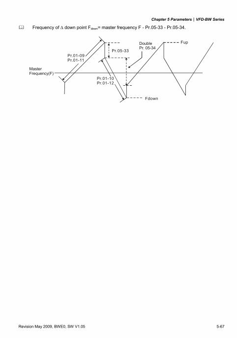
Chapter 5 Parameters|VFD-BW Series
Revision May 2009, BWE0, SW V1.05 5-67
Frequency of Δ down point Fdown= master frequency F - Pr.05-33 - Pr.05-34.
Fup
Fdown
Pr.01-09Pr.01-11
Pr.01-10Pr.01-12
Pr.05-33
MasterFrequency(F)
Double Pr. 05-34
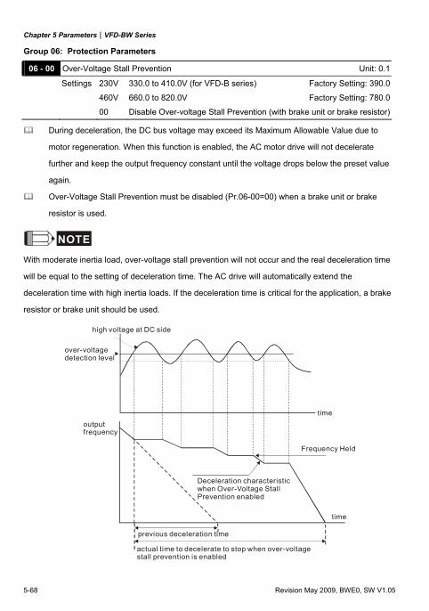
Chapter 5 Parameters|VFD-BW Series
5-68 Revision May 2009, BWE0, SW V1.05
Group 06: Protection Parameters
06 - 00 Over-Voltage Stall Prevention Unit: 0.1
Settings 230V 330.0 to 410.0V (for VFD-B series) Factory Setting: 390.0
460V 660.0 to 820.0V Factory Setting: 780.0
00 Disable Over-voltage Stall Prevention (with brake unit or brake resistor)
During deceleration, the DC bus voltage may exceed its Maximum Allowable Value due to
motor regeneration. When this function is enabled, the AC motor drive will not decelerate
further and keep the output frequency constant until the voltage drops below the preset value
again.
Over-Voltage Stall Prevention must be disabled (Pr.06-00=00) when a brake unit or brake
resistor is used.
NOTE
With moderate inertia load, over-voltage stall prevention will not occur and the real deceleration time
will be equal to the setting of deceleration time. The AC drive will automatically extend the
deceleration time with high inertia loads. If the deceleration time is critical for the application, a brake
resistor or brake unit should be used.
high voltage at DC side
over-voltage detection level
outputfrequency
time
Deceleration characteristicwhen Over-Voltage StallPrevention enabled
Frequency Held
time
previous deceleration time
actual time to decelerate to stop when over-voltage stall prevention is enabled
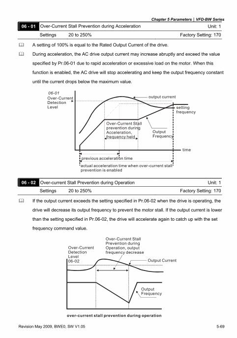
Chapter 5 Parameters|VFD-BW Series
Revision May 2009, BWE0, SW V1.05 5-69
06 - 01 Over-Current Stall Prevention during Acceleration Unit: 1
Settings 20 to 250% Factory Setting: 170
A setting of 100% is equal to the Rated Output Current of the drive.
During acceleration, the AC drive output current may increase abruptly and exceed the value
specified by Pr.06-01 due to rapid acceleration or excessive load on the motor. When this
function is enabled, the AC drive will stop accelerating and keep the output frequency constant
until the current drops below the maximum value.
06-01Over-CurrentDetectionLevel
Output Frequency
Over-Current Stallprevention duringAcceleration,frequency held
output current
time
settingfrequency
previous acceleration time
actual acceleration time when over-current stall prevention is enabled
06 - 02 Over-current Stall Prevention during Operation Unit: 1
Settings 20 to 250% Factory Setting: 170
If the output current exceeds the setting specified in Pr.06-02 when the drive is operating, the
drive will decrease its output frequency to prevent the motor stall. If the output current is lower
than the setting specified in Pr.06-02, the drive will accelerate again to catch up with the set
frequency command value.
Over-CurrentDetectionLevel06-02 Output Current
OutputFrequency
Over-Current StallPrevention duringOperation, outputfrequency decrease
over-current stall prevention during operation
Chapter 5 Parameters|VFD-BW Series
5-70 Revision May 2009, BWE0, SW V1.05
06 - 03 Over-Torque Detection Mode (OL2)
Factory Setting: 00
Settings 00 Over-Torque detection disabled.
01 Over-Torque detection enabled during constant speed operation. After over-torque is detected, keep running until OL1 or OL occurs.
02 Over-Torque detection enabled during constant speed operation. After over-torque is detected, stop running.
03 Over-Torque detection enabled during acceleration. After over-torque is detected, keep running until OL1 or OL occurs.
04 Over-Torque detection enabled during acceleration. After over-torque is detected, stop running.
This parameter determines the operation mode of the drive after the over-torque (OL2) is
detected via the following method: if the output current exceeds the over-torque detection level
(Pr.06-04) longer than the setting of Pr.06-05 Over-Torque Detection Time, the warning
message “OL2” is displayed. If a Multi-Functional Output Terminal is set to over-torque
detection (Pr.03-00~03-03=04), the output is on. Please refer to Pr.03-00~03-03 for details.
06 - 04 Over-Torque Detection Level (OL2) Unit: 1
Settings 10 to 200% Factory Setting: 150
This setting is proportional to the Rated Output Current of the drive.
06 - 05 Over-Torque Detection Time (OL2) Unit: 0.1
Settings 0.1 to 60.0 sec Factory Setting: 0.1
This parameter sets the time for how long over-torque must be detected before “OL2” is
displayed.
06 - 06 Electronic Thermal Overload Relay Selection (OL1)
Factory Setting: 02
Settings 00 Operate with a Standard Motor (self-cooled by fan)
01 Operate with a Special Motor (forced external cooling)
02 Operation disabled
This function is used to protect the motor from overloading or overheating.
06 - 07 Electronic Thermal Characteristic Unit: 1
Settings 30 to 600 sec Factory Setting: 60
The parameter determines the time required for activating the I2t electronic thermal protection
function. The graph below shows I2t curves for 150% output power for 1 minute.
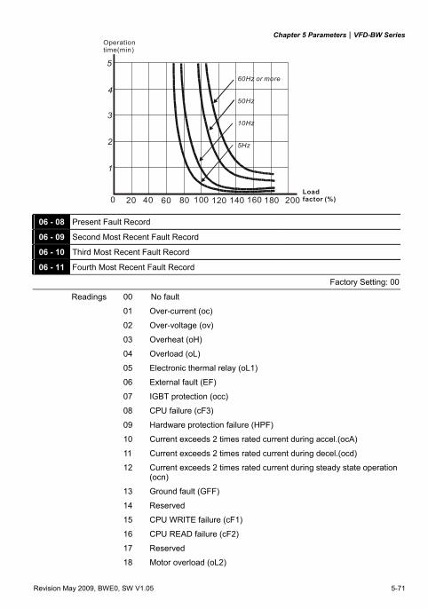
Chapter 5 Parameters|VFD-BW Series
Revision May 2009, BWE0, SW V1.05 5-71
1
2
3
4
5
60Hz or more
50Hz
10Hz
5Hz
0 20 40 60 80 100 120 140 160 180 200
Operationtime(min)
Loadfactor (%)
06 - 08 Present Fault Record
06 - 09 Second Most Recent Fault Record
06 - 10 Third Most Recent Fault Record
06 - 11 Fourth Most Recent Fault Record
Factory Setting: 00
Readings 00 No fault
01 Over-current (oc)
02 Over-voltage (ov)
03 Overheat (oH)
04 Overload (oL)
05 Electronic thermal relay (oL1)
06 External fault (EF)
07 IGBT protection (occ)
08 CPU failure (cF3)
09 Hardware protection failure (HPF)
10 Current exceeds 2 times rated current during accel.(ocA)
11 Current exceeds 2 times rated current during decel.(ocd)
12 Current exceeds 2 times rated current during steady state operation (ocn)
13 Ground fault (GFF)
14 Reserved
15 CPU WRITE failure (cF1)
16 CPU READ failure (cF2)
17 Reserved
18 Motor overload (oL2)
Chapter 5 Parameters|VFD-BW Series
5-72 Revision May 2009, BWE0, SW V1.05
19 Auto accel/decel failure (CFA)
20 Software/password protection (codE)
21 Emergency stop (EF1)
22 Phase-Loss (PHL)
23 Preliminary count value attained, EF active (cEF)
24 Low current (Lc)
25 Analog feedback signal error (AnLEr)
26 PG feedback signal error (PGErr)
27 Motor overheat (oH9F)
28 Motor overheat warning (oH9L)
29 Fan Power Fault (FAnP)
30 Fan 1 Fault (FF1)
31 Fan 2 Fault (FF2)
32 Fan 3 Fault (FF3)
33 Fan 1, 2, 3 Fault (FFo)
34 Fan 1, 2 Fault (FF12)
35 Fan 1, 3 Fault (FF13)
36 Fan 2, 3 Fault (FF23)
37 Gate Drive Low Voltage Protect (Fv)
38 Error PID feedback of tension (rFbE)
39 Broken line detection of tension (rLbr)
In Pr.06-08 to Pr.06-11 the four most recent faults that occurred, are stored. After removing the
cause of the fault, use the reset command to reset the drive.
06 - 12 Low Current Detection Level Unit: 1
Settings 00 ~ 100% Factory Setting: 00
00 Disabled
06 - 13 Low Current Detection Time Unit: 0.1
Settings 0.1 to 3600.0 sec Factory Setting: 10.0
06 - 14 Low Current Detection Mode
Factory Setting: 00
Settings 00 Warn and keep operating
01 Warn and ramp to stop
02 Warn and coast to stop
03 Warn, after coast to stop, restart (delay 06-15 setting time)
Chapter 5 Parameters|VFD-BW Series
Revision May 2009, BWE0, SW V1.05 5-73
06 - 15 Low Current Detection Restart Delay Time Unit: 0.1
Settings 1 to 600 min Factory Setting: 10
If output current is lower than the setting Pr.06-12 for a time that exceeds Pr.06-13 setting
during operation, the AC drive will warn per Pr.06-14 setting. If Pr.06-14 is set to 03, the AC
drive will restart after the delay time set by Pr.06-15 is up.
06 - 16 User-Defined Low-Voltage Detection Level (Lv) Unit: 1
Settings 00 Disabled
230V: 220 ~ 300VDC (for VFD-B series) Factory Setting: 00
460V: 440 ~ 600VDC Factory Setting: 00
06 - 17 User-Defined Low-Voltage Detection Time Unit: 0.1
Settings 0.1 to 3600.0 sec Factory Setting: 0.5
When the DC BUS voltage is lower than the setting of Pr.06-16 for a time exceeding the
setting of Pr.06-17, the AC motor drive will output a signal when Pr.03-00 ~ Pr.03-03 is set to
28.
06 - 18 Reserved
06 - 19 User-Defined Low-Voltage Treatment
Factory Setting: 00
Settings 00 No action
01 EF active
06 - 20 Reserved
06 - 21 Reserved
06 - 22 Reserved
Chapter 5 Parameters|VFD-BW Series
5-74 Revision May 2009, BWE0, SW V1.05
Group 07: Motor Parameters
07 - 00 Motor Rated Current Unit: 1
Settings 30 to 120% Factory Setting: 100
Use the following formula to calculate the percentage value entered into this parameter:
(Motor Current / AC Drive Current) x 100%
with Motor Current=Motor rated current in A shown to motor nameplate
AC Drive Current=Rated current of AC drive in A (see Pr.00-01)
Pr.07-00 and Pr.07-01 must be set if the drive is programmed to operate in Vector Control
mode (Pr.0-09 = 2 or 3). They also must be set if the "Electronic Thermal Overload Relay"
(Pr.06-06) or "Slip Compensation" functions are selected.
07 - 01 Motor No-load Current Unit: 1
Settings 01 to 90% Factory Setting: 40
The rated current of the AC drive is regarded as 100%. The setting of the Motor no-load
current will affect the slip compensation.
The setting value must be less than Pr.07-00 (Motor Rated Current).
07 - 02 Torque Compensation Unit: 0.1
Settings 0.0 to 10.0 Factory Setting: 0.0
This parameter may be set so that the AC drive will increase its voltage output to obtain a
higher torque. Only to be used for V/f control mode.
Too high torque compensation can overheat the motor.
07 - 03 Slip Compensation (Used without PG) Unit: 0.01
Settings 0.00 to 3.00 Factory Setting: 0.00
While driving an asynchronous motor, increasing the load on the AC motor drive will cause an
increase in slip and decrease in speed. This parameter may be used to compensate the slip by
increasing the output frequency. When the output current of the AC motor drive is bigger than
the motor no-load current (Pr.07-01), the AC drive will adjust its output frequency according to
this parameter.
07 - 04 Number of Motor Poles Unit: 2
Settings 02 to 10 Factory Setting: 04
This parameter sets the number of motor poles (must be an even number).
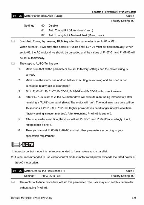
Chapter 5 Parameters|VFD-BW Series
Revision May 2009, BWE0, SW V1.05 5-75
07 - 05 Motor Parameters Auto Tuning Unit: 1
Factory Setting: 00
Settings 00 Disable
01 Auto Tuning R1 (Motor doesn’t run.)
02 Auto Tuning R1 + No-load Test (Motor runs.)
Start Auto Tuning by pressing RUN key after this parameter is set to 01 or 02.
When set to 01, it will only auto detect R1 value and Pr.07-01 must be input manually. When
set to 02, the AC motor drive should be unloaded and the values of Pr.07-01 and Pr.07-06 will
be set automatically.
The steps to AUTO-Tuning are: 1. Make sure that all the parameters are set to factory settings and the motor wiring is
correct.
2. Make sure the motor has no-load before executing auto-tuning and the shaft is not
connected to any belt or gear motor.
3. Fill in Pr.01-01, Pr.01-02, Pr.07-00, Pr.07-04 and Pr.07-08 with correct values.
4. After Pr.07-05 is set to 2, the AC motor drive will execute auto-tuning immediately after
receiving a ”RUN” command. (Note: The motor will run!). The total auto tune time will be
15 seconds + Pr.01-09 + Pr.01-10. Higher power drives need longer Accel/|Decel time
(factory setting is recommended). After executing, Pr.07-05 is set to 0.
5. After successful execution, the drive will set Pr.07-01 and Pr.07-06 accordingly. If not,
repeat steps 3 and 4.
6. Then you can set Pr.00-09 to 02/03 and set other parameters according to your
application requirement.
NOTE
1. In vector control mode it is not recommended to have motors run in parallel.
2. It is not recommended to use vector control mode if motor rated power exceeds the rated power of
the AC motor drive.
07 - 06 Motor Line-to-line Resistance R1 Unit: 1
Settings 00 to 65535 mΩ Factory Setting: 00
The motor auto tune procedure will set this parameter. The user may also set this parameter
without using Pr.07-05.
Chapter 5 Parameters|VFD-BW Series
5-76 Revision May 2009, BWE0, SW V1.05
07 - 07 Reserved
07 - 08 Motor Rated Slip Unit: 0.01
Settings 0.00 to 20.00Hz Factory Setting: 3.00
Refer to the rated rpm and the number of poles on the nameplate of the motor and use the
following equation to calculate the rated slip.
Rated Slip (Hz) = Fbase (Pr.01-01 base frequency) - (rated rpm x motor pole/120)
This parameter is valid only in vector mode.
07 - 09 Slip Compensation Limit Unit: 1
Settings 00 to 250% Factory Setting: 200
This parameter sets the upper limit of the compensation frequency (the percentage of Pr.07-
08).
Example: when Pr.07-08=5Hz and Pr.07-09=150%, the upper limit of the compensation
frequency is 7.5Hz. Therefore, for a 50Hz motor, the max. output is 57.5Hz.
07 - 10 Reserved
07 - 11 Reserved
07 - 12 Torque Compensation Time Constant Unit: 0.01
Settings 0.01 to 10.00 sec Factory Setting: 0.05
07 - 13 Slip Compensation Time Constant Unit: 0.01
Settings 0.05 to 10.00 sec Factory Setting: 0.10
Setting Pr.07-12 and Pr.07-13 changes the response time for the compensation. When Pr.07-12 and Pr.07-13 are set to 10.00 sec, its response time for the compensation will
be the longest. But if the settings are too short, unstable system may occur.
07 - 14 Accumulative Motor Operation Time (Min.) Unit: 1
Settings 00 to 1439 Factory Setting: 00
07 - 15 Accumulative Motor Operation Time (Day) Unit: 1
Settings 00 to 65535 Factory Setting: 00
Pr.07-14 and Pr.07-15 are used to record the motor operation time. They can be cleared by
setting to 00 and it is not recorded when the motor operation time is less than 60 seconds.
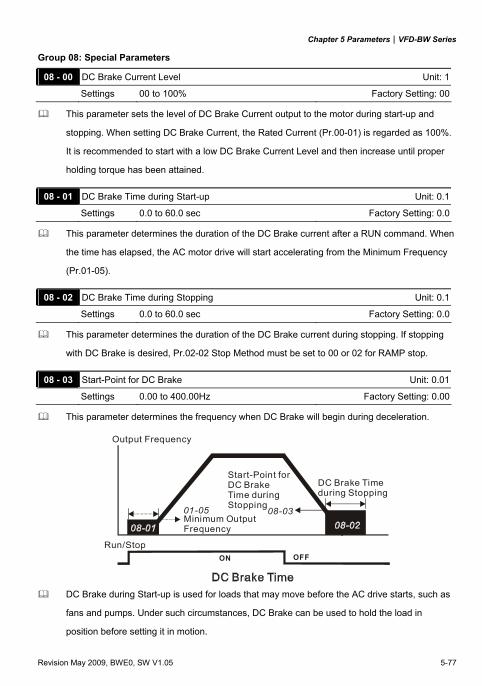
Chapter 5 Parameters|VFD-BW Series
Revision May 2009, BWE0, SW V1.05 5-77
Group 08: Special Parameters
08 - 00 DC Brake Current Level Unit: 1
Settings 00 to 100% Factory Setting: 00
This parameter sets the level of DC Brake Current output to the motor during start-up and
stopping. When setting DC Brake Current, the Rated Current (Pr.00-01) is regarded as 100%.
It is recommended to start with a low DC Brake Current Level and then increase until proper
holding torque has been attained.
08 - 01 DC Brake Time during Start-up Unit: 0.1
Settings 0.0 to 60.0 sec Factory Setting: 0.0
This parameter determines the duration of the DC Brake current after a RUN command. When
the time has elapsed, the AC motor drive will start accelerating from the Minimum Frequency
(Pr.01-05).
08 - 02 DC Brake Time during Stopping Unit: 0.1
Settings 0.0 to 60.0 sec Factory Setting: 0.0
This parameter determines the duration of the DC Brake current during stopping. If stopping
with DC Brake is desired, Pr.02-02 Stop Method must be set to 00 or 02 for RAMP stop.
08 - 03 Start-Point for DC Brake Unit: 0.01
Settings 0.00 to 400.00Hz Factory Setting: 0.00
This parameter determines the frequency when DC Brake will begin during deceleration.
Run/StopON OFF
01-05 08-03
Output Frequency
Minimum OutputFrequency
Start-Point forDC BrakeTime duringStopping
DC Brake Timeduring Stopping
DC Brake during Start-up is used for loads that may move before the AC drive starts, such as
fans and pumps. Under such circumstances, DC Brake can be used to hold the load in
position before setting it in motion.
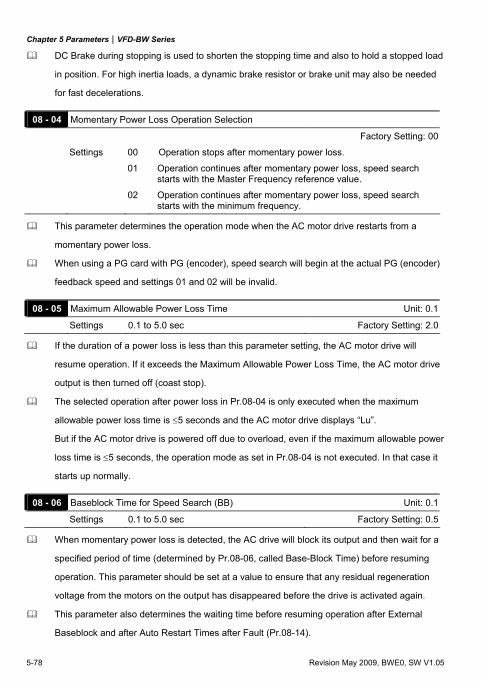
Chapter 5 Parameters|VFD-BW Series
5-78 Revision May 2009, BWE0, SW V1.05
DC Brake during stopping is used to shorten the stopping time and also to hold a stopped load
in position. For high inertia loads, a dynamic brake resistor or brake unit may also be needed
for fast decelerations.
08 - 04 Momentary Power Loss Operation Selection
Factory Setting: 00
Settings 00 Operation stops after momentary power loss.
01 Operation continues after momentary power loss, speed search starts with the Master Frequency reference value.
02 Operation continues after momentary power loss, speed search starts with the minimum frequency.
This parameter determines the operation mode when the AC motor drive restarts from a
momentary power loss.
When using a PG card with PG (encoder), speed search will begin at the actual PG (encoder)
feedback speed and settings 01 and 02 will be invalid.
08 - 05 Maximum Allowable Power Loss Time Unit: 0.1
Settings 0.1 to 5.0 sec Factory Setting: 2.0
If the duration of a power loss is less than this parameter setting, the AC motor drive will
resume operation. If it exceeds the Maximum Allowable Power Loss Time, the AC motor drive
output is then turned off (coast stop).
The selected operation after power loss in Pr.08-04 is only executed when the maximum
allowable power loss time is ≤5 seconds and the AC motor drive displays “Lu”.
But if the AC motor drive is powered off due to overload, even if the maximum allowable power
loss time is ≤5 seconds, the operation mode as set in Pr.08-04 is not executed. In that case it
starts up normally.
08 - 06 Baseblock Time for Speed Search (BB) Unit: 0.1
Settings 0.1 to 5.0 sec Factory Setting: 0.5
When momentary power loss is detected, the AC drive will block its output and then wait for a
specified period of time (determined by Pr.08-06, called Base-Block Time) before resuming
operation. This parameter should be set at a value to ensure that any residual regeneration
voltage from the motors on the output has disappeared before the drive is activated again.
This parameter also determines the waiting time before resuming operation after External
Baseblock and after Auto Restart Times after Fault (Pr.08-14).
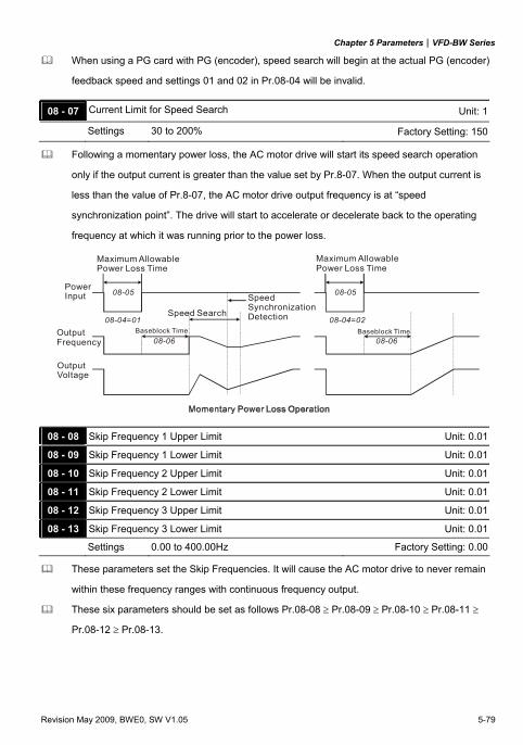
Chapter 5 Parameters|VFD-BW Series
Revision May 2009, BWE0, SW V1.05 5-79
When using a PG card with PG (encoder), speed search will begin at the actual PG (encoder)
feedback speed and settings 01 and 02 in Pr.08-04 will be invalid.
08 - 07 Current Limit for Speed Search Unit: 1
Settings 30 to 200% Factory Setting: 150
Following a momentary power loss, the AC motor drive will start its speed search operation
only if the output current is greater than the value set by Pr.8-07. When the output current is
less than the value of Pr.8-07, the AC motor drive output frequency is at “speed
synchronization point”. The drive will start to accelerate or decelerate back to the operating
frequency at which it was running prior to the power loss.
OutputFrequency
OutputVoltage
08-06
08-05
08-04=01
08-06
08-05
08-04=02
PowerInput
Maximum AllowablePower Loss Time
Baseblock Time
Speed Search
SpeedSynchronizationDetection
Baseblock Time
Maximum AllowablePower Loss Time
08 - 08 Skip Frequency 1 Upper Limit Unit: 0.01
08 - 09 Skip Frequency 1 Lower Limit Unit: 0.01
08 - 10 Skip Frequency 2 Upper Limit Unit: 0.01
08 - 11 Skip Frequency 2 Lower Limit Unit: 0.01
08 - 12 Skip Frequency 3 Upper Limit Unit: 0.01
08 - 13 Skip Frequency 3 Lower Limit Unit: 0.01
Settings 0.00 to 400.00Hz Factory Setting: 0.00
These parameters set the Skip Frequencies. It will cause the AC motor drive to never remain
within these frequency ranges with continuous frequency output.
These six parameters should be set as follows Pr.08-08 ≥ Pr.08-09 ≥ Pr.08-10 ≥ Pr.08-11 ≥
Pr.08-12 ≥ Pr.08-13.
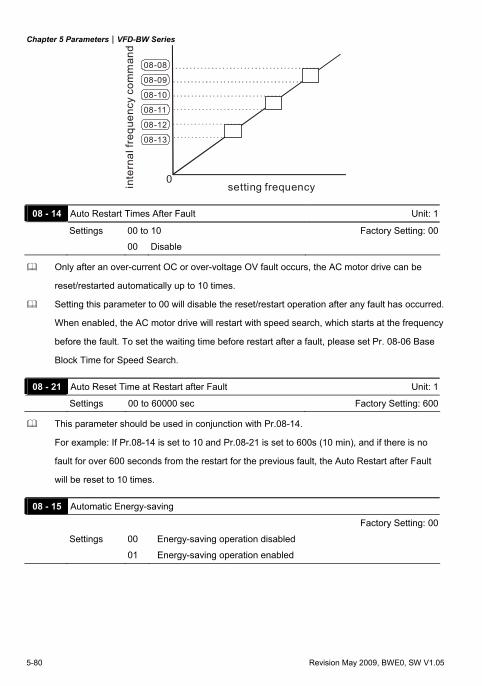
Chapter 5 Parameters|VFD-BW Series
5-80 Revision May 2009, BWE0, SW V1.05
0
08-08
08-09
08-10
08-11
08-12
08-13
setting frequencyinte
rnal
freq
uenc
y co
mm
and
08 - 14 Auto Restart Times After Fault Unit: 1
Settings 00 to 10 Factory Setting: 00
00 Disable
Only after an over-current OC or over-voltage OV fault occurs, the AC motor drive can be
reset/restarted automatically up to 10 times.
Setting this parameter to 00 will disable the reset/restart operation after any fault has occurred.
When enabled, the AC motor drive will restart with speed search, which starts at the frequency
before the fault. To set the waiting time before restart after a fault, please set Pr. 08-06 Base
Block Time for Speed Search.
08 - 21 Auto Reset Time at Restart after Fault Unit: 1
Settings 00 to 60000 sec Factory Setting: 600
This parameter should be used in conjunction with Pr.08-14.
For example: If Pr.08-14 is set to 10 and Pr.08-21 is set to 600s (10 min), and if there is no
fault for over 600 seconds from the restart for the previous fault, the Auto Restart after Fault
will be reset to 10 times.
08 - 15 Automatic Energy-saving
Factory Setting: 00
Settings 00 Energy-saving operation disabled
01 Energy-saving operation enabled
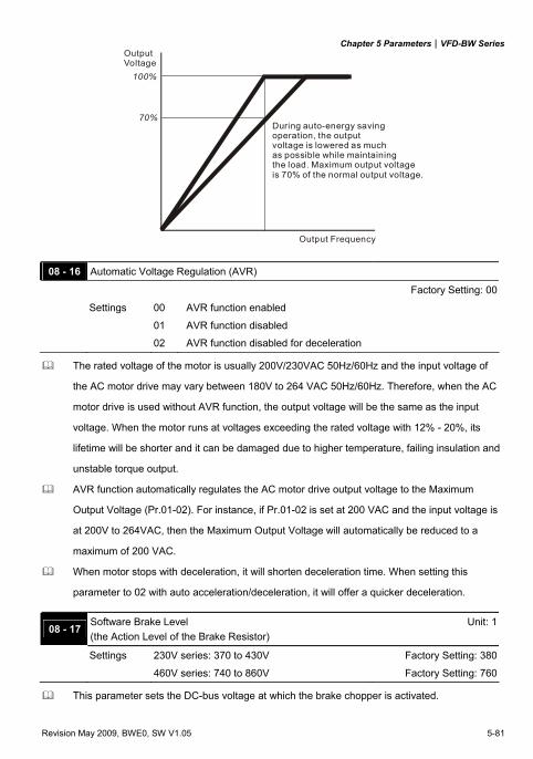
Chapter 5 Parameters|VFD-BW Series
Revision May 2009, BWE0, SW V1.05 5-81
70%
100%
OutputVoltage
Output Frequency
During auto-energy saving operation, the output voltage is lowered as much as possible while maintaining the load. Maximum output voltage is 70% of the normal output voltage.
08 - 16 Automatic Voltage Regulation (AVR)
Factory Setting: 00
Settings 00 AVR function enabled
01 AVR function disabled
02 AVR function disabled for deceleration
The rated voltage of the motor is usually 200V/230VAC 50Hz/60Hz and the input voltage of
the AC motor drive may vary between 180V to 264 VAC 50Hz/60Hz. Therefore, when the AC
motor drive is used without AVR function, the output voltage will be the same as the input
voltage. When the motor runs at voltages exceeding the rated voltage with 12% - 20%, its
lifetime will be shorter and it can be damaged due to higher temperature, failing insulation and
unstable torque output.
AVR function automatically regulates the AC motor drive output voltage to the Maximum
Output Voltage (Pr.01-02). For instance, if Pr.01-02 is set at 200 VAC and the input voltage is
at 200V to 264VAC, then the Maximum Output Voltage will automatically be reduced to a
maximum of 200 VAC.
When motor stops with deceleration, it will shorten deceleration time. When setting this
parameter to 02 with auto acceleration/deceleration, it will offer a quicker deceleration.
08 - 17 Software Brake Level (the Action Level of the Brake Resistor)
Unit: 1
Settings 230V series: 370 to 430V Factory Setting: 380
460V series: 740 to 860V Factory Setting: 760
This parameter sets the DC-bus voltage at which the brake chopper is activated.
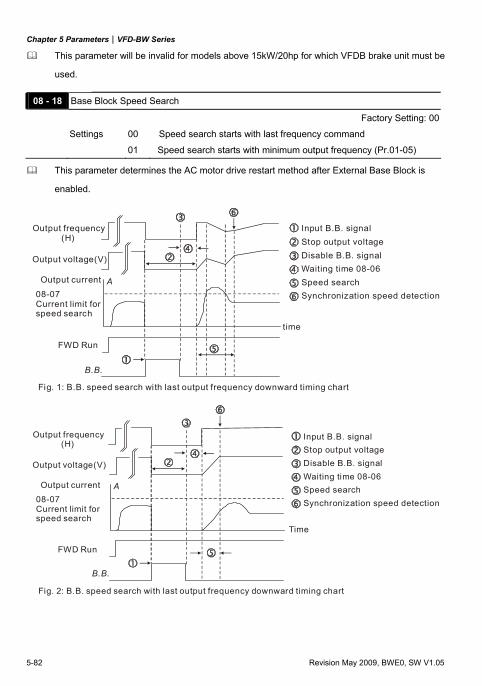
Chapter 5 Parameters|VFD-BW Series
5-82 Revision May 2009, BWE0, SW V1.05
This parameter will be invalid for models above 15kW/20hp for which VFDB brake unit must be
used.
08 - 18 Base Block Speed Search
Factory Setting: 00
Settings 00 Speed search starts with last frequency command
01 Speed search starts with minimum output frequency (Pr.01-05)
This parameter determines the AC motor drive restart method after External Base Block is
enabled.
B.B.
A
Input B.B. signalStop output voltageDisable B.B. signalWaiting time 08-06Speed searchSynchronization speed detection
time
Fig. 1: B.B. speed search with last output frequency downward timing chart
FWD Run
Output current
Output voltage(V)
Output frequency (H)
08-07Current limit forspeed search
B.B.
A
Input B.B. signalStop output voltageDisable B.B. signalWaiting time 08-06Speed searchSynchronization speed detection
Fig. 2: B.B. speed search with last output frequency downward timing chart
FWD Run
Output current
Output voltage(V)
Output frequency (H)
08-07Current limit forspeed search
Time
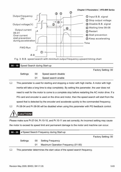
Chapter 5 Parameters|VFD-BW Series
Revision May 2009, BWE0, SW V1.05 5-83
B.B.
A
Input B.B. signalStop output voltageDisable B.B. signalWaiting time 08-06RestartStall preventionKeep accelerating
Fig. 3: B.B. speed search with minimum output frequency upward timing chart
FWD Run
Output current
Output voltage(V)
Output frequency (H)
06-01Over currentstall preventionduring acceleration
Time
08 - 19 Speed Search during Start-up
Factory Setting: 00
Settings 00 Speed search disable
01 Speed search enable
This parameter is used for starting and stopping a motor with high inertia. A motor with high
inertia will take a long time to stop completely. By setting this parameter, the user does not
need to wait for the motor to come to a complete stop before restarting the AC motor drive. If a
PG card and encoder is used on the drive and motor, then the speed search will start from the
speed that is detected by the encoder and accelerate quickly to the commanded frequency.
Pr.08-04 and Pr.08-06 will be disabled when using this parameter with PG feedback control.
CAUTION!
Please make sure Pr.07-04, Pr.10-10, and Pr.10-11 are set correctly. An incorrect setting may cause
the motor to exceed its speed limit and permanent damage to the motor and machine can occur.
08 - 20 Speed Search Frequency during Start-up
Factory Setting: 00
Settings 00 Setting Frequency
01 Maximum Operation Frequency (01-00)
This parameter determines the start value of the speed search frequency.
Chapter 5 Parameters|VFD-BW Series
5-84 Revision May 2009, BWE0, SW V1.05
08 - 22 Compensation Coefficient for Motor Instability Unit: 1
Settings 00 to 1000 Factory Setting: 00
The drift current occurs in a specific zone and causes motor instability. By using this parameter,
motor instability greatly improves.
The drift current zone of the larger horsepower motor is usually in the low frequency range.
A setting of more than 500 is recommended.
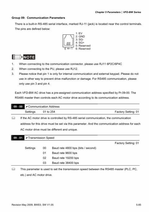
Chapter 5 Parameters|VFD-BW Series
Revision May 2009, BWE0, SW V1.05 5-85
Group 09: Communication Parameters
There is a built-in RS-485 serial interface, marked RJ-11 (jack) is located near the control terminals.
The pins are defined below:
6 1
1: EV2: GND3: SG-4: SG+5: Reserved6: Reserved
NOTE
1. When connecting to the communication connector, please use RJ11 6P2C/6P4C
2. When connecting to the PU, please use RJ12.
3. Please notice that pin 1 is only for internal communication and external keypad. Please do not
use in other way to prevent drive malfunction or damage. For RS485 communication, please
only use pin 3 and pin 4.
Each VFD-BW AC drive has a pre-assigned communication address specified by Pr.09-00. The
RS485 master then controls each AC motor drive according to its communication address.
09 - 00 Communication Address
Settings 01 to 254 Factory Setting: 01
If the AC motor drive is controlled by RS-485 serial communication, the communication
address for this drive must be set via this parameter. And the communication address for each
AC motor drive must be different and unique.
09 - 01 Transmission Speed
Factory Setting: 01
Settings 00 Baud rate 4800 bps (bits / second)
01 Baud rate 9600 bps
02 Baud rate 19200 bps
03 Baud rate 38400 bps
This parameter is used to set the transmission speed between the RS485 master (PLC, PC,
etc.) and AC motor drive.
Chapter 5 Parameters|VFD-BW Series
5-86 Revision May 2009, BWE0, SW V1.05
09 - 02 Transmission Fault Treatment
Factory Setting: 03
Settings 00 Warn and keep operating
01 Warn and RAMP to stop
02 Warn and COAST to stop
03 No warning and keep operating
This parameter is set to how to react if transmission errors occur.
See list of error messages below (see section 3.6.)
09 - 03 Time-out Detection Unit: 0.1
Settings 0.0 to 60.0 sec Factory Setting: 0.0
0.0 Disable
If Pr.09-03 is not equal to 0.0, Pr.09-02=00~02, and there is no communication on the bus
during the Time Out detection period (set by Pr.09-03), “cE10” will be shown on the keypad.
09 - 04 Communication Protocol
Factory Setting: 00
Settings 00 Modbus ASCII mode, protocol <7,N,2>
01 Modbus ASCII mode, protocol <7,E,1>
02 Modbus ASCII mode, protocol <7,O,1>
03 Modbus RTU mode, protocol <8,N,2>
04 Modbus RTU mode, protocol <8,E,1>
05 Modbus RTU mode, protocol <8,O,1>
1. Control by PC or PLC
A VFD-BW can be set up to communicate on Modbus networks using one of the following modes:
ASCII (American Standard Code for Information Interchange) or RTU (Remote Terminal Unit).
Users can select the desired mode along with the serial port communication protocol in Pr.09-04.
Code Description:
ASCII mode:
Each 8-bit data is the combination of two ASCII characters. For example, a 1-byte data: 64 Hex,
shown as ‘64’ in ASCII, consists of ‘6’ (36Hex) and ‘4’ (34Hex). Character ‘0’ ‘1’ ‘2’ ‘3’ ‘4’ ‘5’ ‘6’ ‘7’
ASCII code 30H 31H 32H 33H 34H 35H 36H 37H
Character ‘8’ ‘9’ ‘A’ ‘B’ ‘C’ ‘D’ ‘E’ ‘F’ ASCII code 38H 39H 41H 42H 43H 44H 45H 46H
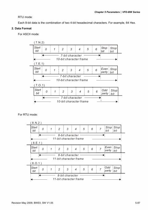
Chapter 5 Parameters|VFD-BW Series
Revision May 2009, BWE0, SW V1.05 5-87
RTU mode:
Each 8-bit data is the combination of two 4-bit hexadecimal characters. For example, 64 Hex. 2. Data Format
For ASCII mode:
( 7.N.2)
( 7.E.1)
Start bit 0 1 2 3 4 5 6 Stop
bit
10-bit character frame
( 7.O.1)
Oddparity
Start bit 0 1 2 3 4 5 6 Stop
bit
10-bit character frame
Evenparity
Start bit 0 1 2 3 4 5 6 Stop
bit
7-bit character
10-bit character frame
Stopbit
7-bit character
7-bit character
For RTU mode:
Start bit 0 1 2 3 4 5 6 Stop
bitStopbit
8-bit character11-bit character frame
( 8.N.2 )
Start bit 0 1 2 3 4 5 6 Even
parityStopbit
11-bit character frame
( 8.E.1 )
Start bit 0 1 2 3 4 5 6 Stop
bit
11-bit character frame
( 8.O.1 )Oddparity
7
7
7
8-bit character
8-bit character
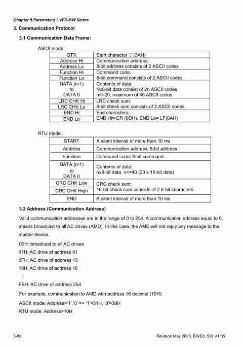
Chapter 5 Parameters|VFD-BW Series
5-88 Revision May 2009, BWE0, SW V1.05
3. Communication Protocol
3.1 Communication Data Frame:
ASCII mode: STX Start character ‘:’ (3AH)
Address Hi Address Lo
Communication address: 8-bit address consists of 2 ASCII codes
Function Hi Function Lo
Command code: 8-bit command consists of 2 ASCII codes
DATA (n-1) to
DATA 0
Contents of data: Nx8-bit data consist of 2n ASCII codes n<=20, maximum of 40 ASCII codes
LRC CHK Hi LRC CHK Lo
LRC check sum: 8-bit check sum consists of 2 ASCII codes
END Hi END Lo
End characters: END Hi= CR (0DH), END Lo= LF(0AH)
RTU mode: START A silent interval of more than 10 ms Address Communication address: 8-bit address Function Command code: 8-bit command
DATA (n-1) to
DATA 0
Contents of data: n×8-bit data, n<=40 (20 x 16-bit data)
CRC CHK Low CRC CHK High
CRC check sum: 16-bit check sum consists of 2 8-bit characters
END A silent interval of more than 10 ms
3.2 Address (Communication Address)
Valid communication addresses are in the range of 0 to 254. A communication address equal to 0,
means broadcast to all AC drives (AMD). In this case, the AMD will not reply any message to the
master device.
00H: broadcast to all AC drives
01H: AC drive of address 01
0FH: AC drive of address 15
10H: AC drive of address 16
:
FEH: AC drive of address 254
For example, communication to AMD with address 16 decimal (10H):
ASCII mode: Address=’1’,’0’ => ‘1’=31H, ‘0’=30H
RTU mode: Address=10H
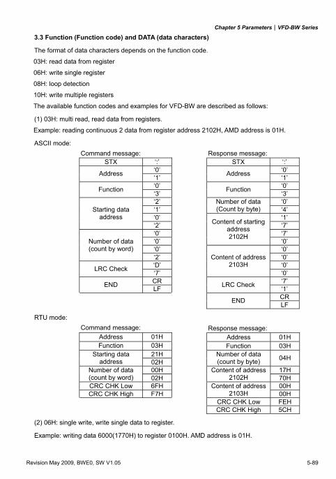
Chapter 5 Parameters|VFD-BW Series
Revision May 2009, BWE0, SW V1.05 5-89
3.3 Function (Function code) and DATA (data characters)
The format of data characters depends on the function code.
03H: read data from register
06H: write single register
08H: loop detection
10H: write multiple registers
The available function codes and examples for VFD-BW are described as follows:
(1) 03H: multi read, read data from registers.
Example: reading continuous 2 data from register address 2102H, AMD address is 01H.
ASCII mode: Command message: Response message:
STX ‘:’ STX ‘:’ ‘0’ ‘0’ Address ‘1’ Address ‘1’ ‘0’ ‘0’ Function ‘3’ Function ‘3’ ‘2’ ‘0’ ‘1’
Number of data (Count by byte) ‘4’
‘0’ ‘1’ Starting data
address ‘2’ ‘7’ ‘0’ ‘7’ ‘0’
Content of starting address 2102H
‘0’ ‘0’ ‘0’
Number of data (count by word)
‘2’ ‘0’ ‘D’ ‘0’ LRC Check ‘7’
Content of address 2103H
‘0’ CR ‘7’ END LF LRC Check ‘1’
CR END LF
RTU mode: Command message: Response message:
Address 01H Address 01H Function 03H Function 03H
21H Starting data address 02H
Number of data (count by byte) 04H
00H 17H Number of data (count by word) 02H
Content of address 2102H 70H
CRC CHK Low 6FH 00H CRC CHK High F7H
Content of address 2103H 00H
CRC CHK Low FEH CRC CHK High 5CH
(2) 06H: single write, write single data to register. Example: writing data 6000(1770H) to register 0100H. AMD address is 01H.
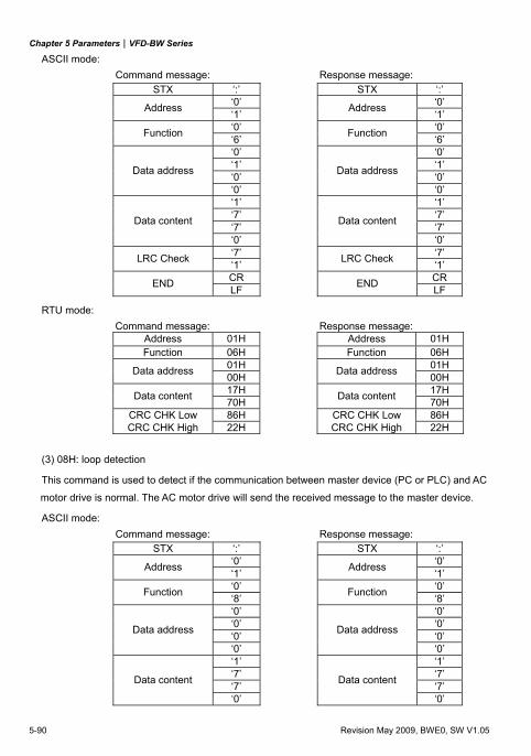
Chapter 5 Parameters|VFD-BW Series
5-90 Revision May 2009, BWE0, SW V1.05
ASCII mode: Command message: Response message:
STX ‘:’ STX ‘:’ ‘0’ ‘0’ Address ‘1’ Address ‘1’ ‘0’ ‘0’ Function ‘6’ Function ‘6’ ‘0’ ‘0’ ‘1’ ‘1’ ‘0’ ‘0’ Data address
‘0’
Data address
‘0’ ‘1’ ‘1’ ‘7’ ‘7’ ‘7’ ‘7’ Data content
‘0’
Data content
‘0’ ‘7’ ‘7’ LRC Check ‘1’ LRC Check ‘1’ CR CR END LF END LF
RTU mode: Command message: Response message:
Address 01H Address 01H Function 06H Function 06H
01H 01H Data address 00H Data address 00H 17H 17H Data content 70H Data content 70H
CRC CHK Low 86H CRC CHK Low 86H CRC CHK High 22H CRC CHK High 22H
(3) 08H: loop detection This command is used to detect if the communication between master device (PC or PLC) and AC
motor drive is normal. The AC motor drive will send the received message to the master device.
ASCII mode: Command message: Response message:
STX ‘:’ STX ‘:’ ‘0’ ‘0’ Address ‘1’ Address ‘1’ ‘0’ ‘0’ Function ‘8’ Function ‘8’ ‘0’ ‘0’ ‘0’ ‘0’ ‘0’ ‘0’ Data address
‘0’
Data address
‘0’ ‘1’ ‘1’ ‘7’ ‘7’ ‘7’ ‘7’ Data content
‘0’
Data content
‘0’
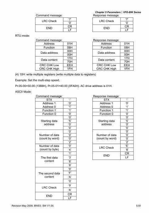
Chapter 5 Parameters|VFD-BW Series
Revision May 2009, BWE0, SW V1.05 5-91
Command message: Response message: ‘7’ ‘7’ LRC Check ‘0’ LRC Check ‘0’ CR CR END LF END LF
RTU mode: Command message: Response message:
Address 01H Address 01H Function 08H Function 08H
00H 00H Data address 00H Data address 00H 17H 17H Data content 70H Data content 70H
CRC CHK Low EEH CRC CHK Low EEH CRC CHK High 1FH CRC CHK High 1FH
(4) 10H: write multiple registers (write multiple data to registers)
Example: Set the multi-step speed,
Pr.05-00=50.00 (1388H), Pr.05-01=40.00 (0FA0H). AC drive address is 01H.
ASCII Mode: Command message: Response message:
STX ‘:’ STX ‘:’ Address 1 ‘0’ Address 1 ‘0’ Address 0 ‘1’ Address 0 ‘1’ Function 1 ‘1’ Function 1 ‘1’ Function 0 ‘0’ Function 0 ‘0’
‘0’ ‘0’ ‘5’ ‘5’ ‘0’ ‘0’
Starting data address
‘0’
Starting data address
‘0’ ‘0’ ‘0’ ‘0’ ‘0’ ‘0’ ‘0’
Number of data (count by word)
‘2’
Number of data (count by word)
‘2’ ‘0’ ‘E’ Number of data
(count by byte) ‘4’ LRC Check
‘8’ ‘1’ CR ‘3’ END LF ‘8’
The first data content
‘8’ ‘0’ ‘F’ ‘A’
The second data content
‘0’ ‘9’
LRC Check ‘A’ CR END LF
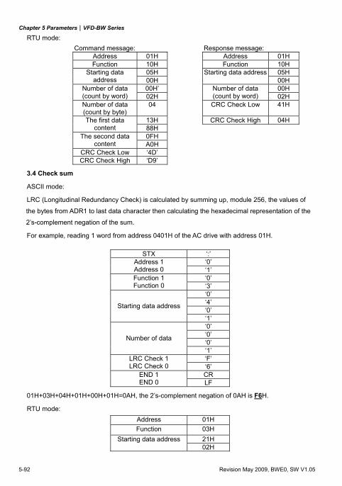
Chapter 5 Parameters|VFD-BW Series
5-92 Revision May 2009, BWE0, SW V1.05
RTU mode: Command message: Response message:
Address 01H Address 01H Function 10H Function 10H
05H 05H Starting data address 00H
Starting data address00H
00H’ 00H Number of data (count by word) 02H
Number of data (count by word) 02H
Number of data (count by byte)
04 CRC Check Low 41H
13H CRC Check High 04H The first data content 88H
0FH The second data content A0H
CRC Check Low ‘4D’ CRC Check High ‘D9’
3.4 Check sum
ASCII mode:
LRC (Longitudinal Redundancy Check) is calculated by summing up, module 256, the values of
the bytes from ADR1 to last data character then calculating the hexadecimal representation of the
2’s-complement negation of the sum.
For example, reading 1 word from address 0401H of the AC drive with address 01H.
STX ‘:’ ‘0’ Address 1
Address 0 ‘1’ ‘0’ Function 1
Function 0 ‘3’ ‘0’ ‘4’ ‘0’ Starting data address
‘1’ ‘0’ ‘0’ ‘0’ Number of data
‘1’ ‘F’ LRC Check 1
LRC Check 0 ‘6’ CR END 1
END 0 LF
01H+03H+04H+01H+00H+01H=0AH, the 2’s-complement negation of 0AH is F6H.
RTU mode: Address 01H Function 03H
21H Starting data address02H
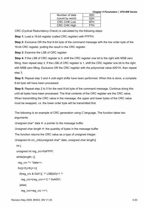
Chapter 5 Parameters|VFD-BW Series
Revision May 2009, BWE0, SW V1.05 5-93
00H Number of data (count by word) 02H CRC CHK Low 6FH CRC CHK High F7H
CRC (Cyclical Redundancy Check) is calculated by the following steps:
Step 1: Load a 16-bit register (called CRC register) with FFFFH.
Step 2: Exclusive OR the first 8-bit byte of the command message with the low order byte of the
16-bit CRC register, putting the result in the CRC register.
Step 3: Examine the LSB of CRC register.
Step 4: If the LSB of CRC register is 0, shift the CRC register one bit to the right with MSB zero
filling, then repeat step 3. If the LSB of CRC register is 1, shift the CRC register one bit to the right
with MSB zero filling, Exclusive OR the CRC register with the polynomial value A001H, then repeat
step 3.
Step 5: Repeat step 3 and 4 until eight shifts have been performed. When this is done, a complete
8-bit byte will have been processed.
Step 6: Repeat step 2 to 5 for the next 8-bit byte of the command message. Continue doing this
until all bytes have been processed. The final contents of the CRC register are the CRC value.
When transmitting the CRC value in the message, the upper and lower bytes of the CRC value
must be swapped, i.e. the lower order byte will be transmitted first.
The following is an example of CRC generation using C language. The function takes two
arguments:
Unsigned char* data a pointer to the message buffer
Unsigned char length the quantity of bytes in the message buffer
The function returns the CRC value as a type of unsigned integer.
Unsigned int crc_chk(unsigned char* data, unsigned char length)
int j;
unsigned int reg_crc=0xFFFF;
while(length--)
reg_crc ^= *data++;
for(j=0;j<8;j++)
if(reg_crc & 0x01) /* LSB(b0)=1 */
reg_crc=(reg_crc>>1) ^ 0xA001;
else
reg_crc=reg_crc >>1;
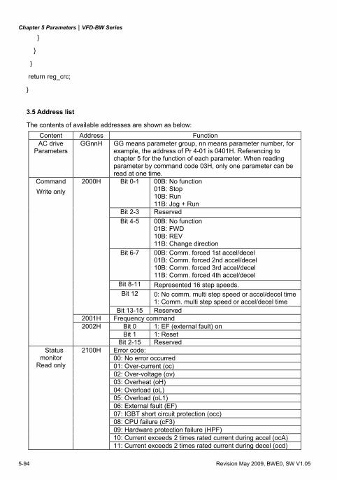
Chapter 5 Parameters|VFD-BW Series
5-94 Revision May 2009, BWE0, SW V1.05
return reg_crc;
3.5 Address list
The contents of available addresses are shown as below: Content Address Function AC drive
Parameters GGnnH GG means parameter group, nn means parameter number, for
example, the address of Pr 4-01 is 0401H. Referencing to chapter 5 for the function of each parameter. When reading parameter by command code 03H, only one parameter can be read at one time.
Bit 0-1 00B: No function 01B: Stop 10B: Run 11B: Jog + Run
Bit 2-3 Reserved Bit 4-5 00B: No function
01B: FWD 10B: REV 11B: Change direction
Bit 6-7 00B: Comm. forced 1st accel/decel 01B: Comm. forced 2nd accel/decel 10B: Comm. forced 3rd accel/decel 11B: Comm. forced 4th accel/decel
Bit 8-11 Represented 16 step speeds. Bit 12 0: No comm. multi step speed or accel/decel time
1: Comm. multi step speed or accel/decel time
Command Write only
2000H
Bit 13-15 Reserved 2001H Frequency command
Bit 0 1: EF (external fault) on Bit 1 1: Reset
2002H
Bit 2-15 Reserved Error code: 00: No error occurred
Status monitor
Read only
2100H
01: Over-current (oc) 02: Over-voltage (ov) 03: Overheat (oH) 04: Overload (oL) 05: Overload (oL1) 06: External fault (EF) 07: IGBT short circuit protection (occ) 08: CPU failure (cF3) 09: Hardware protection failure (HPF) 10: Current exceeds 2 times rated current during accel (ocA) 11: Current exceeds 2 times rated current during decel (ocd)
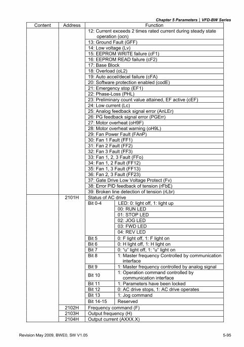
Chapter 5 Parameters|VFD-BW Series
Revision May 2009, BWE0, SW V1.05 5-95
Content Address Function 12: Current exceeds 2 times rated current during steady state
operation (ocn) 13: Ground Fault (GFF) 14: Low voltage (Lv) 15: EEPROM WRITE failure (cF1) 16: EEPROM READ failure (cF2) 17: Base Block 18: Overload (oL2) 19: Auto accel/decel failure (cFA) 20: Software protection enabled (codE) 21: Emergency stop (EF1) 22: Phase-Loss (PHL) 23: Preliminary count value attained, EF active (cEF) 24: Low current (Lc) 25: Analog feedback signal error (AnLEr) 26: PG feedback signal error (PGErr) 27: Motor overheat (oH9F) 28: Motor overheat warning (oH9L) 29: Fan Power Fault (FAnP) 30: Fan 1 Fault (FF1) 31: Fan 2 Fault (FF2) 32: Fan 3 Fault (FF3) 33: Fan 1, 2, 3 Fault (FFo) 34: Fan 1, 2 Fault (FF12) 35: Fan 1, 3 Fault (FF13) 36: Fan 2, 3 Fault (FF23) 37: Gate Drive Low Voltage Protect (Fv) 38: Error PID feedback of tension (rFbE) 39: Broken line detection of tension (rLbr)
Status of AC drive LED: 0: light off, 1: light up 00: RUN LED 01: STOP LED 02: JOG LED 03: FWD LED
2101H Bit 0-4
04: REV LED Bit 5 0: F light off, 1: F light on Bit 6 0: H light off, 1: H light on Bit 7 0: “u” light off, 1: “u” light on Bit 8 1: Master frequency Controlled by communication
interface Bit 9 1: Master frequency controlled by analog signal
Bit 10 1: Operation command controlled by communication interface
Bit 11 1: Parameters have been locked Bit 12 0: AC drive stops, 1: AC drive operates Bit 13 1: Jog command
Bit 14-15 Reserved 2102H Frequency command (F) 2103H Output frequency (H) 2104H Output current (AXXX.X)
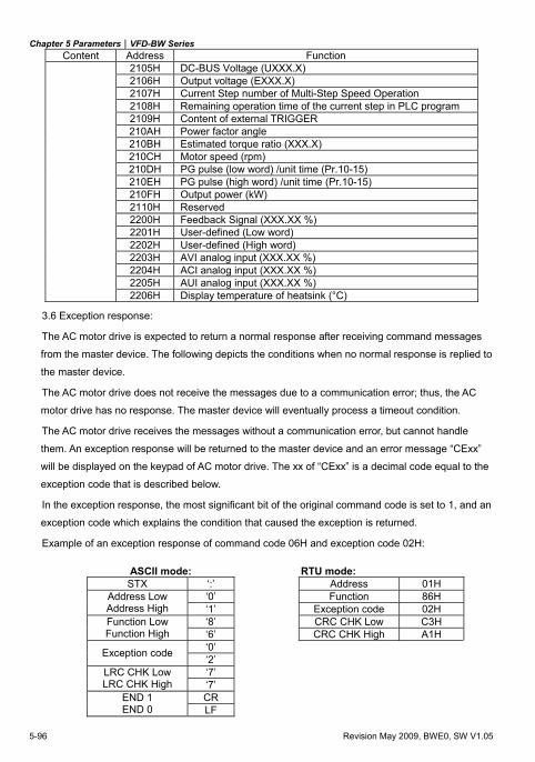
Chapter 5 Parameters|VFD-BW Series
5-96 Revision May 2009, BWE0, SW V1.05
Content Address Function 2105H DC-BUS Voltage (UXXX.X) 2106H Output voltage (EXXX.X) 2107H Current Step number of Multi-Step Speed Operation 2108H Remaining operation time of the current step in PLC program
2109H Content of external TRIGGER 210AH Power factor angle
210BH Estimated torque ratio (XXX.X) 210CH Motor speed (rpm) 210DH PG pulse (low word) /unit time (Pr.10-15) 210EH PG pulse (high word) /unit time (Pr.10-15) 210FH Output power (kW) 2110H Reserved 2200H Feedback Signal (XXX.XX %) 2201H User-defined (Low word) 2202H User-defined (High word) 2203H AVI analog input (XXX.XX %) 2204H ACI analog input (XXX.XX %) 2205H AUI analog input (XXX.XX %) 2206H Display temperature of heatsink (°C)
3.6 Exception response:
The AC motor drive is expected to return a normal response after receiving command messages
from the master device. The following depicts the conditions when no normal response is replied to
the master device.
The AC motor drive does not receive the messages due to a communication error; thus, the AC
motor drive has no response. The master device will eventually process a timeout condition.
The AC motor drive receives the messages without a communication error, but cannot handle
them. An exception response will be returned to the master device and an error message “CExx”
will be displayed on the keypad of AC motor drive. The xx of “CExx” is a decimal code equal to the
exception code that is described below.
In the exception response, the most significant bit of the original command code is set to 1, and an
exception code which explains the condition that caused the exception is returned.
Example of an exception response of command code 06H and exception code 02H:
ASCII mode: RTU mode: STX ‘:’ Address 01H
‘0’ Function 86H Address Low Address High ‘1’ Exception code 02H
‘8’ CRC CHK Low C3H Function Low Function High ‘6’ CRC CHK High A1H
‘0’ Exception code ‘2’ ‘7’ LRC CHK Low
LRC CHK High ‘7’ CR END 1
END 0 LF
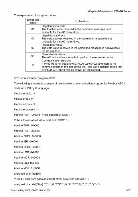
Chapter 5 Parameters|VFD-BW Series
Revision May 2009, BWE0, SW V1.05 5-97
The explanation of exception codes: Exception
code Explanation
01 Illegal function code: The function code received in the command message is not available for the AC motor drive.
02 Illegal data address: The data address received in the command message is not available for the AC motor drive.
03 Illegal data value: The data value received in the command message is not available for the AC drive.
04 Slave device failure: The AC motor drive is unable to perform the requested action.
10
Communication time-out: If Pr.09-03 is not equal to 0.0, Pr.09-02=00~02, and there is no communication on the bus during the Time Out detection period (set by Pr.09-03), “cE10” will be shown on the keypad.
3.7 Communication program of PC:
The following is a simple example of how to write a communication program for Modbus ASCII
mode on a PC by C language.
#include<stdio.h>
#include<dos.h>
#include<conio.h>
#include<process.h>
#define PORT 0x03F8 /* the address of COM1 */
/* the address offset value relative to COM1 */
#define THR 0x0000
#define RDR 0x0000
#define BRDL 0x0000
#define IER 0x0001
#define BRDH 0x0001
#define LCR 0x0003
#define MCR 0x0004
#define LSR 0x0005
#define MSR 0x0006
unsigned char rdat[60];
/* read 2 data from address 2102H of AC drive with address 1 */
unsigned char tdat[60]=':','0','1','0','3','2','1','0',’2', '0','0','0','2','D','7','\r','\n';
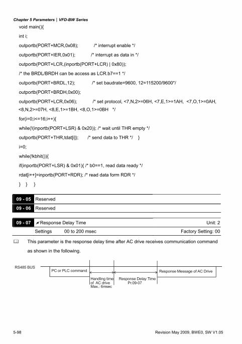
Chapter 5 Parameters|VFD-BW Series
5-98 Revision May 2009, BWE0, SW V1.05
void main()
int i;
outportb(PORT+MCR,0x08); /* interrupt enable */
outportb(PORT+IER,0x01); /* interrupt as data in */
outportb(PORT+LCR,(inportb(PORT+LCR) | 0x80));
/* the BRDL/BRDH can be access as LCR.b7==1 */
outportb(PORT+BRDL,12); /* set baudrate=9600, 12=115200/9600*/
outportb(PORT+BRDH,0x00);
outportb(PORT+LCR,0x06); /* set protocol, <7,N,2>=06H, <7,E,1>=1AH, <7,O,1>=0AH,
<8,N,2>=07H, <8,E,1>=1BH, <8,O,1>=0BH */
for(i=0;i<=16;i++)
while(!(inportb(PORT+LSR) & 0x20)); /* wait until THR empty */
outportb(PORT+THR,tdat[i]); /* send data to THR */
i=0;
while(!kbhit())
if(inportb(PORT+LSR) & 0x01) /* b0==1, read data ready */
rdat[i++]=inportb(PORT+RDR); /* read data form RDR */
09 - 05 Reserved 09 - 06 Reserved
09 - 07 Response Delay Time Unit: 2
Settings 00 to 200 msec Factory Setting: 00
This parameter is the response delay time after AC drive receives communication command
as shown in the following.
RS485 BUSPC or PLC command
Handling time of AC drive
Response Delay Time
Response Message of AC Drive
Max.: 6msec Pr.09-07
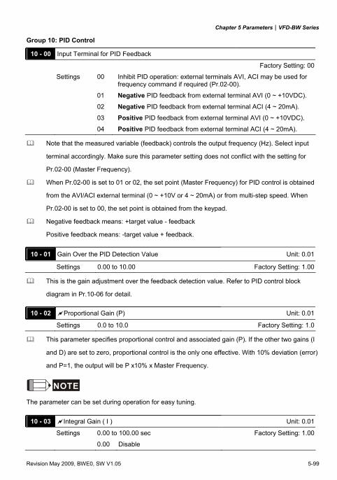
Chapter 5 Parameters|VFD-BW Series
Revision May 2009, BWE0, SW V1.05 5-99
Group 10: PID Control
10 - 00 Input Terminal for PID Feedback
Factory Setting: 00
Settings 00 Inhibit PID operation: external terminals AVI, ACI may be used for frequency command if required (Pr.02-00).
01 Negative PID feedback from external terminal AVI (0 ~ +10VDC).
02 Negative PID feedback from external terminal ACI (4 ~ 20mA).
03 Positive PID feedback from external terminal AVI (0 ~ +10VDC).
04 Positive PID feedback from external terminal ACI (4 ~ 20mA).
Note that the measured variable (feedback) controls the output frequency (Hz). Select input
terminal accordingly. Make sure this parameter setting does not conflict with the setting for
Pr.02-00 (Master Frequency).
When Pr.02-00 is set to 01 or 02, the set point (Master Frequency) for PID control is obtained
from the AVI/ACI external terminal (0 ~ +10V or 4 ~ 20mA) or from multi-step speed. When
Pr.02-00 is set to 00, the set point is obtained from the keypad.
Negative feedback means: +target value - feedback
Positive feedback means: -target value + feedback.
10 - 01 Gain Over the PID Detection Value Unit: 0.01
Settings 0.00 to 10.00 Factory Setting: 1.00
This is the gain adjustment over the feedback detection value. Refer to PID control block
diagram in Pr.10-06 for detail.
10 - 02 Proportional Gain (P) Unit: 0.01
Settings 0.0 to 10.0 Factory Setting: 1.0
This parameter specifies proportional control and associated gain (P). If the other two gains (I
and D) are set to zero, proportional control is the only one effective. With 10% deviation (error)
and P=1, the output will be P x10% x Master Frequency.
NOTE
The parameter can be set during operation for easy tuning.
10 - 03 Integral Gain ( I ) Unit: 0.01
Settings 0.00 to 100.00 sec Factory Setting: 1.00
0.00 Disable
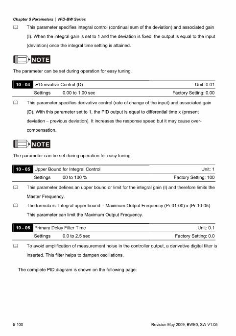
Chapter 5 Parameters|VFD-BW Series
5-100 Revision May 2009, BWE0, SW V1.05
This parameter specifies integral control (continual sum of the deviation) and associated gain
(I). When the integral gain is set to 1 and the deviation is fixed, the output is equal to the input
(deviation) once the integral time setting is attained.
NOTE
The parameter can be set during operation for easy tuning.
10 - 04 Derivative Control (D) Unit: 0.01
Settings 0.00 to 1.00 sec Factory Setting: 0.00
This parameter specifies derivative control (rate of change of the input) and associated gain
(D). With this parameter set to 1, the PID output is equal to differential time x (present
deviation − previous deviation). It increases the response speed but it may cause over-
compensation.
NOTE
The parameter can be set during operation for easy tuning.
10 - 05 Upper Bound for Integral Control Unit: 1
Settings 00 to 100 % Factory Setting: 100
This parameter defines an upper bound or limit for the integral gain (I) and therefore limits the
Master Frequency.
The formula is: Integral upper bound = Maximum Output Frequency (Pr.01-00) x (Pr.10-05).
This parameter can limit the Maximum Output Frequency.
10 - 06 Primary Delay Filter Time Unit: 0.1
Settings 0.0 to 2.5 sec Factory Setting: 0.0
To avoid amplification of measurement noise in the controller output, a derivative digital filter is
inserted. This filter helps to dampen oscillations.
The complete PID diagram is shown on the following page:
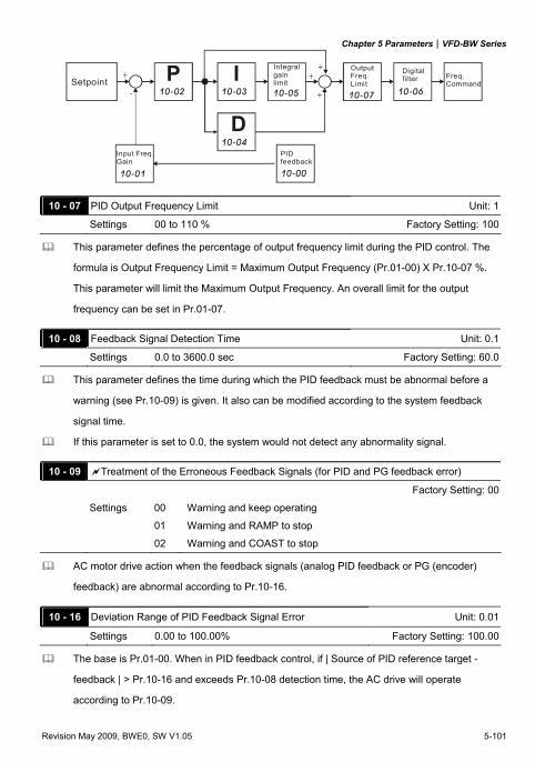
Chapter 5 Parameters|VFD-BW Series
Revision May 2009, BWE0, SW V1.05 5-101
P10-02
I10-03
D10-04
10-05
10-01
10-07 10-06
10-00
+
-
+
+
+Setpoint
Input Freq.Gain
PIDfeedback
Integral gainlimit
Output Freq.Limit
Digitalfilter Freq.
Command
10 - 07 PID Output Frequency Limit Unit: 1
Settings 00 to 110 % Factory Setting: 100
This parameter defines the percentage of output frequency limit during the PID control. The
formula is Output Frequency Limit = Maximum Output Frequency (Pr.01-00) X Pr.10-07 %.
This parameter will limit the Maximum Output Frequency. An overall limit for the output
frequency can be set in Pr.01-07.
10 - 08 Feedback Signal Detection Time Unit: 0.1
Settings 0.0 to 3600.0 sec Factory Setting: 60.0
This parameter defines the time during which the PID feedback must be abnormal before a
warning (see Pr.10-09) is given. It also can be modified according to the system feedback
signal time.
If this parameter is set to 0.0, the system would not detect any abnormality signal.
10 - 09 Treatment of the Erroneous Feedback Signals (for PID and PG feedback error)
Factory Setting: 00
Settings 00 Warning and keep operating
01 Warning and RAMP to stop
02 Warning and COAST to stop
AC motor drive action when the feedback signals (analog PID feedback or PG (encoder)
feedback) are abnormal according to Pr.10-16.
10 - 16 Deviation Range of PID Feedback Signal Error Unit: 0.01
Settings 0.00 to 100.00% Factory Setting: 100.00
The base is Pr.01-00. When in PID feedback control, if | Source of PID reference target -
feedback | > Pr.10-16 and exceeds Pr.10-08 detection time, the AC drive will operate
according to Pr.10-09.
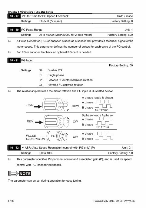
Chapter 5 Parameters|VFD-BW Series
5-102 Revision May 2009, BWE0, SW V1.05
10 - 17 Filter Time for PG Speed Feedback Unit: 2 msec
Settings 0 to 500 (*2 msec) Factory Setting: 0
10 - 10 PG Pulse Range Unit: 1
Settings 00 to 40000 (Max=20000 for 2-pole motor) Factory Setting: 600
A Pulse Generator (PG) or encoder is used as a sensor that provides a feedback signal of the
motor speed. This parameter defines the number of pulses for each cycle of the PG control.
For PG or encoder feedback an optional PG-card is needed.
10 - 11 PG Input
Factory Setting: 00
Settings 00 Disable PG
01 Single phase
02 Forward / Counterclockwise rotation
03 Reverse / Clockwise rotation
The relationship between the motor rotation and PG input is illustrated below:
FWD CCW
REV CW
PULSE GENERATOR
PG
10-11=02
10-11=03
A phase leads B phase
A phase
A phase
A phase
B phase
B phase
B phaseCW
B phase leads A phase
10 - 12 ASR (Auto Speed Regulation) control (with PG only) (P) Unit: 0.1
Settings 0.0 to 10.0 Factory Setting: 1.0
This parameter specifies Proportional control and associated gain (P), and is used for speed
control with PG (encoder) feedback.
NOTE
The parameter can be set during operation for easy tuning.
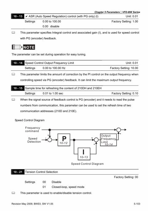
Chapter 5 Parameters|VFD-BW Series
Revision May 2009, BWE0, SW V1.05 5-103
10 - 13 ASR (Auto Speed Regulation) control (with PG only) (I) Unit: 0.01
Settings 0.00 to 100.00 Factory Setting: 1.00
0.00 disable
This parameter specifies Integral control and associated gain (I), and is used for speed control
with PG (encoder) feedback.
NOTE
The parameter can be set during operation for easy tuning.
10 - 14 Speed Control Output Frequency Limit Unit: 0.01
Settings 0.00 to 100.00 Hz Factory Setting: 10.00
This parameter limits the amount of correction by the PI control on the output frequency when
controlling speed via PG (encoder) feedback. It can limit the maximum output frequency.
10 - 15 Sample time for refreshing the content of 210DH and 210EH
Settings 0.01 to 1.00 sec Factory Setting: 0.10
When the signal source of feedback control is PG (encoder) and it needs to read the pulse
numbers from communication, this parameter can be used to set the refresh time of two
communication addresses (210D and 210E).
Speed Control Diagram
10-13I
P10-12 10-14
+- +
+
+
Speed Control Diagram
Frequency command
Speed Detection
OutputFrequencyLimit
10 - 21 Tension Control Selection
Factory Setting: 00
Settings 00 Disable
01 Closed-loop, speed mode
This parameter is used to enable/disable tension control.
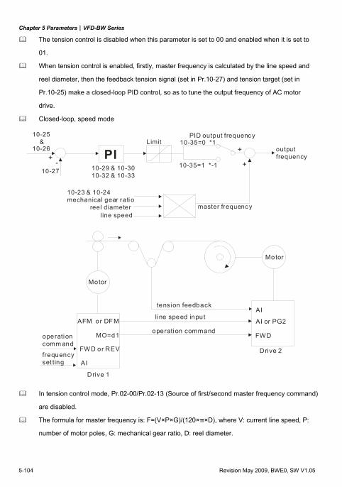
Chapter 5 Parameters|VFD-BW Series
5-104 Revision May 2009, BWE0, SW V1.05
The tension control is disabled when this parameter is set to 00 and enabled when it is set to
01.
When tension control is enabled, firstly, master frequency is calculated by the line speed and
reel diameter, then the feedback tension signal (set in Pr.10-27) and tension target (set in
Pr.10-25) make a closed-loop PID control, so as to tune the output frequency of AC motor
drive.
Closed-loop, speed mode
+-
10-25 & 10-26
10-27
PI10-29 & 10-3010-32 & 10-33
Limit +
+
PID output frequenc y10-35=0 *1
10-35=1 *-1
10-23 & 10-24mechanical gear rati o
output frequency
master frequencyreel diameterline speed
Motor
Motor
AFM or DFM
AI
FW D or REV
MO=d1
AI
AI or PG2
FW D
Drive 1
Drive 2frequencyset ting
operationcomm and
tension feedback
line speed input
operation command
In tension control mode, Pr.02-00/Pr.02-13 (Source of first/second master frequency command)
are disabled.
The formula for master frequency is: F=(V×P×G)/(120×π×D), where V: current line speed, P:
number of motor poles, G: mechanical gear ratio, D: reel diameter.
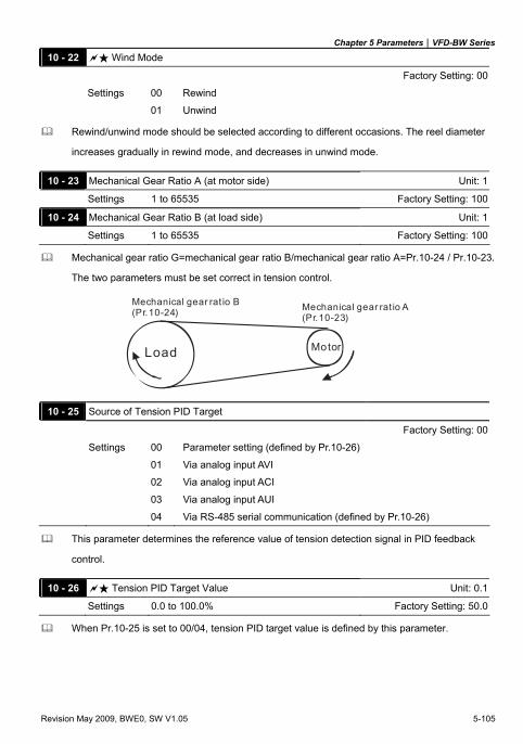
Chapter 5 Parameters|VFD-BW Series
Revision May 2009, BWE0, SW V1.05 5-105
10 - 22 Wind Mode
Factory Setting: 00
Settings 00 Rewind
01 Unwind
Rewind/unwind mode should be selected according to different occasions. The reel diameter
increases gradually in rewind mode, and decreases in unwind mode.
10 - 23 Mechanical Gear Ratio A (at motor side) Unit: 1
Settings 1 to 65535 Factory Setting: 100
10 - 24 Mechanical Gear Ratio B (at load side) Unit: 1
Settings 1 to 65535 Factory Setting: 100
Mechanical gear ratio G=mechanical gear ratio B/mechanical gear ratio A=Pr.10-24 / Pr.10-23.
The two parameters must be set correct in tension control.
Load Motor
Mechanical gear rat io B (Pr.10-24) Mechanical gear rat io A
(Pr.10-23)
10 - 25 Source of Tension PID Target
Factory Setting: 00
Settings 00 Parameter setting (defined by Pr.10-26)
01 Via analog input AVI
02 Via analog input ACI
03 Via analog input AUI
04 Via RS-485 serial communication (defined by Pr.10-26)
This parameter determines the reference value of tension detection signal in PID feedback
control.
10 - 26 Tension PID Target Value Unit: 0.1
Settings 0.0 to 100.0% Factory Setting: 50.0
When Pr.10-25 is set to 00/04, tension PID target value is defined by this parameter.
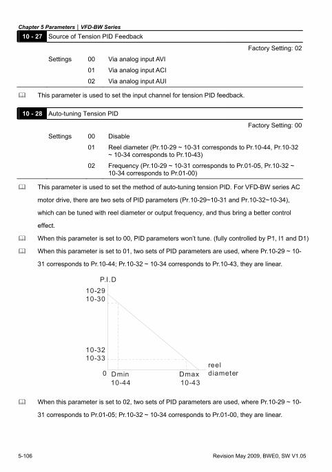
Chapter 5 Parameters|VFD-BW Series
5-106 Revision May 2009, BWE0, SW V1.05
10 - 27 Source of Tension PID Feedback
Factory Setting: 02
Settings 00 Via analog input AVI
01 Via analog input ACI
02 Via analog input AUI
This parameter is used to set the input channel for tension PID feedback.
10 - 28 Auto-tuning Tension PID
Factory Setting: 00
Settings 00 Disable
01 Reel diameter (Pr.10-29 ~ 10-31 corresponds to Pr.10-44, Pr.10-32 ~ 10-34 corresponds to Pr.10-43)
02 Frequency (Pr.10-29 ~ 10-31 corresponds to Pr.01-05, Pr.10-32 ~ 10-34 corresponds to Pr.01-00)
This parameter is used to set the method of auto-tuning tension PID. For VFD-BW series AC
motor drive, there are two sets of PID parameters (Pr.10-29~10-31 and Pr.10-32~10-34),
which can be tuned with reel diameter or output frequency, and thus bring a better control
effect.
When this parameter is set to 00, PID parameters won’t tune. (fully controlled by P1, I1 and D1)
When this parameter is set to 01, two sets of PID parameters are used, where Pr.10-29 ~ 10-
31 corresponds to Pr.10-44; Pr.10-32 ~ 10-34 corresponds to Pr.10-43, they are linear.
10-2910-30
P.I.D
0
10-3210-33
10-44 10-43DmaxDmin
reel diameter
When this parameter is set to 02, two sets of PID parameters are used, where Pr.10-29 ~ 10-
31 corresponds to Pr.01-05; Pr.10-32 ~ 10-34 corresponds to Pr.01-00, they are linear.
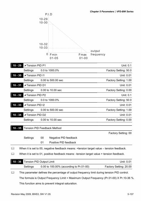
Chapter 5 Parameters|VFD-BW Series
Revision May 2009, BWE0, SW V1.05 5-107
FmaxFmin
10-2910-30
P.I.D
0
10-3210-33
01-05 01-00
outputfrequency
10 - 29 Tension PID P1 Unit: 0.1
Settings 0.0 to 1000.0% Factory Setting: 50.0
10 - 30 Tension PID I1 Unit: 0.01
Settings 0.00 to 500.00 sec Factory Setting: 1.00
10 - 31 Tension PID D1 Unit: 0.01
Settings 0.00 to 10.00 sec Factory Setting: 0.00
10 - 32 Tension PID P2 Unit: 0.1
Settings 0.0 to 1000.0% Factory Setting: 50.0
10 - 33 Tension PID I2 Unit: 0.01
Settings 0.00 to 500.00 sec Factory Setting: 1.00
10 - 34 Tension PID D2 Unit: 0.01
Settings 0.00 to 10.00 sec Factory Setting: 0.00
10 - 35 Tension PID Feedback Method
Factory Setting: 00
Settings 00 Negative PID feedback
01 Positive PID feedback
When it is set to 00, negative feedback means: +tension target value – tension feedback.
When it is set to 01, positive feedback means: -tension target value + tension feedback.
10 - 36 Tension PID Output Limit Unit: 0.01
Settings 0.00 to 100.00% (according to Pr.01-00) Factory Setting: 20.00
This parameter defines the percentage of output frequency limit during tension PID control.
The formula is Output Frequency Limit = Maximum Output Frequency (Pr.01-00) X Pr.10-36 %.
This function aims to prevent integral saturation.
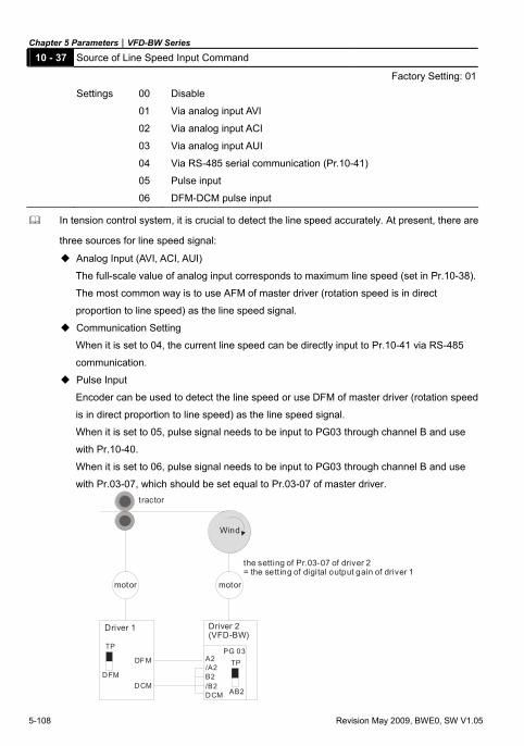
Chapter 5 Parameters|VFD-BW Series
5-108 Revision May 2009, BWE0, SW V1.05
10 - 37 Source of Line Speed Input Command
Factory Setting: 01
Settings 00 Disable
01 Via analog input AVI
02 Via analog input ACI
03 Via analog input AUI
04 Via RS-485 serial communication (Pr.10-41)
05 Pulse input
06 DFM-DCM pulse input
In tension control system, it is crucial to detect the line speed accurately. At present, there are
three sources for line speed signal:
Analog Input (AVI, ACI, AUI)
The full-scale value of analog input corresponds to maximum line speed (set in Pr.10-38).
The most common way is to use AFM of master driver (rotation speed is in direct
proportion to line speed) as the line speed signal.
Communication Setting
When it is set to 04, the current line speed can be directly input to Pr.10-41 via RS-485
communication.
Pulse Input
Encoder can be used to detect the line speed or use DFM of master driver (rotation speed
is in direct proportion to line speed) as the line speed signal.
When it is set to 05, pulse signal needs to be input to PG03 through channel B and use
with Pr.10-40.
When it is set to 06, pulse signal needs to be input to PG03 through channel B and use
with Pr.03-07, which should be set equal to Pr.03-07 of master driver.
TP
DFM
DF M
DCM
TP
AB2
A2/A2B2/B2DCM
PG 03
tractor
motor motor
Driver 1 Driver 2(VFD-BW)
the setting of Pr.03-07 of driver 2= the setting of digital output gain of driver 1
Wind
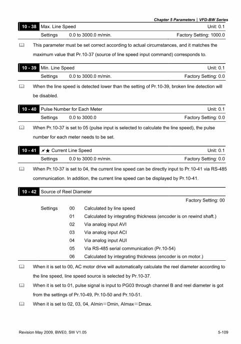
Chapter 5 Parameters|VFD-BW Series
Revision May 2009, BWE0, SW V1.05 5-109
10 - 38 Max. Line Speed Unit: 0.1
Settings 0.0 to 3000.0 m/min. Factory Setting: 1000.0
This parameter must be set correct according to actual circumstances, and it matches the
maximum value that Pr.10-37 (source of line speed input command) corresponds to.
10 - 39 Min. Line Speed Unit: 0.1
Settings 0.0 to 3000.0 m/min. Factory Setting: 0.0
When the line speed is detected lower than the setting of Pr.10-39, broken line detection will
be disabled.
10 - 40 Pulse Number for Each Meter Unit: 0.1
Settings 0.0 to 3000.0 Factory Setting: 0.0
When Pr.10-37 is set to 05 (pulse input is selected to calculate the line speed), the pulse
number for each meter needs to be set.
10 - 41 Current Line Speed Unit: 0.1
Settings 0.0 to 3000.0 m/min. Factory Setting: 0.0
When Pr.10-37 is set to 04, the current line speed can be directly input to Pr.10-41 via RS-485
communication. In addition, the current line speed can be displayed by Pr.10-41.
10 - 42 Source of Reel Diameter
Factory Setting: 00
Settings 00 Calculated by line speed
01 Calculated by integrating thickness (encoder is on rewind shaft.)
02 Via analog input AVI
03 Via analog input ACI
04 Via analog input AUI
05 Via RS-485 serial communication (Pr.10-54)
06 Calculated by integrating thickness (encoder is on motor.)
When it is set to 00, AC motor drive will automatically calculate the reel diameter according to
the line speed, line speed source is selected by Pr.10-37.
When it is set to 01, pulse signal is input to PG03 through channel B and reel diameter is got
from the settings of Pr.10-49, Pr.10-50 and Pr.10-51.
When it is set to 02, 03, 04, AImin=Dmin, AImax=Dmax.
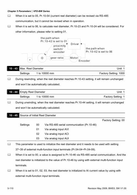
Chapter 5 Parameters|VFD-BW Series
5-110 Revision May 2009, BWE0, SW V1.05
When it is set to 05, Pr.10-54 (current reel diameter) can be revised via RS-485
communication, but it cannot be revised when in operation.
When it is set to 06, to calculate reel diameter, Pr.10-23 and Pr.10-24 will be considered. For
other information, please refer to setting 01.
the path when Pr.10-42 is set to 01
Driverthe path when Pr.10-42 is set to 06
gear ratio MotorEncoder
proxi mityswitch/encoder
10 - 43 Max. Reel Diameter Unit: 1
Settings 1 to 10000 mm Factory Setting: 1000
During rewinding, when the reel diameter reaches Pr.10-43 setting, it will remain unchanged
and won’t be automatically calculated.
10 - 44 Empty Reel Diameter Unit: 1
Settings 1 to 10000 mm Factory Setting: 1
During unwinding, when the reel diameter reaches Pr.10-44 setting, it will remain unchanged
and won’t be automatically calculated.
10 - 45 Source of Initial Reel Diameter
Factory Setting: 00
Settings 00 Via RS-485 serial communication (Pr.10-46)
01 Via analog input AVI
02 Via analog input ACI
03 Via analog input AUI
This parameter is used to initialize the reel diameter and it needs to be used with setting
37~39 of external multi-function input terminals (Pr.04-04~Pr.04-09).
When it is set to 00, a value is assigned to Pr.10-46 via RS-485 serial communication. And the
reel diameter is initialized to the value of Pr.10-46 by using with external multi-function input
terminals.
When it is set to 01, 02, 03, the reel diameter is initialized to AI current value by using with
external multi-function input terminals.
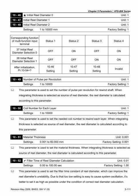
Chapter 5 Parameters|VFD-BW Series
Revision May 2009, BWE0, SW V1.05 5-111
10 - 46 Initial Reel Diameter 0 Unit: 1
10 - 47 Initial Reel Diameter 1 Unit: 1
10 - 48 Initial Reel Diameter 2 Unit: 1
Settings 1 to 10000 mm Factory Setting: 1
Corresponding function of multi-function input
terminal Status 1 Status 2 Status 3 Status 4
37 Initial Reel Diameter Selection 0 OFF ON OFF ON
38 Initial Reel Diameter Selection 1 OFF OFF ON ON
After initialization, Pr.10-54=?
10-46 Setting
10-47 Setting
10-48 Setting
Invalid
10 - 49 Number of Pulse per Revolution Unit: 1
Settings 1 to 10000 Factory Setting: 1
This parameter is used to set the number of pulse per revolution for rewind shaft. When
integrating thickness is selected as source of reel diameter, the reel diameter is calculated
according to this parameter.
10 - 50 Coil Number for Each Layer Unit: 1
Settings 1 to 10000 Factory Setting: 1
This parameter is used to set the needed coil number to rewind each layer. When integrating
thickness is selected as source of reel diameter, the reel diameter is calculated according to
this parameter.
10 - 51 Material Thickness Unit: 0.001
Settings 0.001 to 60.000 mm Factory Setting: 0.001
This parameter is used to set the material thickness. When integrating thickness is selected as
source of reel diameter, the reel diameter is calculated according to this parameter.
10 - 52 Filter Time of Reel Diameter Calculation Unit: 0.01
Settings 0.00 to 100.00 sec Factory Setting: 1.00
This parameter is used to set the filter time constant of reel diameter, which can improve the
reel diameter’s unstability. Due to that too low setting is easy to cause system oscillation, it’s
better to set it as high as possible under the condition of correct reel diameter calculation.
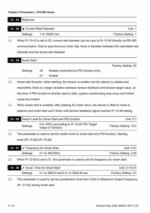
Chapter 5 Parameters|VFD-BW Series
5-112 Revision May 2009, BWE0, SW V1.05
10 - 53 Reserved
10 - 54 Current Reel Diameter Unit: 1
Settings 1 to 10000 mm Factory Setting: 1
When Pr.10-42 is set to 05, current reel diameter can be input to Pr.10-54 directly via RS-485
communication. Due to asynchronous motor slip, there is deviation between the calculated reel
diameter and the actual reel diameter.
10 - 55 Smart Start
Factory Setting: 00
Settings 00 Disable (controlled by PID function only)
01 Enable
Smart start function: when starting, the tension is smaller and the dancer is unbalanced,
meanwhile, there is a larger deviation between tension feedback and tension target value, at
this time, if PID function is directly used to start, system overshooting may occur and further
cause line broken.
When smart start is enabled, after starting AC motor drive, the dancer is lifted to close to
balance and smart start won’t finish until tension feedback signal reaches Pr.10-56 setting.
10 - 56 Switch Level for Smart Start and PID function Unit: 0.1
Settings 0 to 100% (according to Pr.10-26 PID Target Value of Tension) Factory Setting: 15.0
This parameter is used to set the switch level for smart start and PID function. Starting
level=(Pr.10-26)-(Pr.10-56)
10 - 57 Frequency for Smart Start Unit: 0.01
Settings 0.1 to 400.00Hz Factory Setting: 2.00
When Pr.10-55 is set to 01, this parameter is used to set the frequency for smart start.
10 - 58 Accel. Time for Smart Start Unit: 0.1/0.01
Settings 0.1 to 3600.0 sec/0.01 to 3600.00 sec Factory Setting: 3.0
This parameter is used to set the acceleration time from 0.0Hz to Maximum Output Frequency
(Pr. 01-00) during smart start.
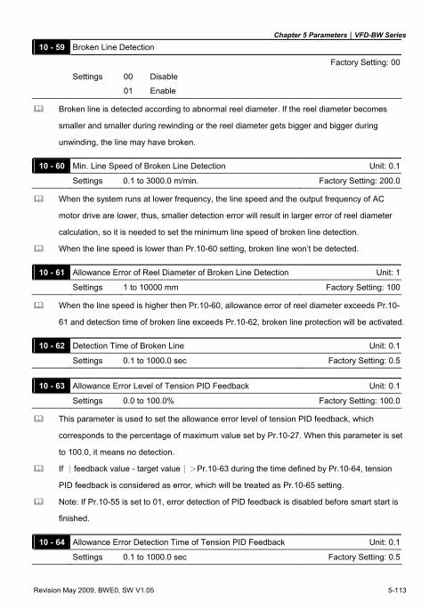
Chapter 5 Parameters|VFD-BW Series
Revision May 2009, BWE0, SW V1.05 5-113
10 - 59 Broken Line Detection
Factory Setting: 00
Settings 00 Disable
01 Enable
Broken line is detected according to abnormal reel diameter. If the reel diameter becomes
smaller and smaller during rewinding or the reel diameter gets bigger and bigger during
unwinding, the line may have broken.
10 - 60 Min. Line Speed of Broken Line Detection Unit: 0.1
Settings 0.1 to 3000.0 m/min. Factory Setting: 200.0
When the system runs at lower frequency, the line speed and the output frequency of AC
motor drive are lower, thus, smaller detection error will result in larger error of reel diameter
calculation, so it is needed to set the minimum line speed of broken line detection.
When the line speed is lower than Pr.10-60 setting, broken line won’t be detected.
10 - 61 Allowance Error of Reel Diameter of Broken Line Detection Unit: 1
Settings 1 to 10000 mm Factory Setting: 100
When the line speed is higher then Pr.10-60, allowance error of reel diameter exceeds Pr.10-
61 and detection time of broken line exceeds Pr.10-62, broken line protection will be activated.
10 - 62 Detection Time of Broken Line Unit: 0.1
Settings 0.1 to 1000.0 sec Factory Setting: 0.5
10 - 63 Allowance Error Level of Tension PID Feedback Unit: 0.1
Settings 0.0 to 100.0% Factory Setting: 100.0
This parameter is used to set the allowance error level of tension PID feedback, which
corresponds to the percentage of maximum value set by Pr.10-27. When this parameter is set
to 100.0, it means no detection.
If ∣feedback value - target value∣>Pr.10-63 during the time defined by Pr.10-64, tension
PID feedback is considered as error, which will be treated as Pr.10-65 setting.
Note: If Pr.10-55 is set to 01, error detection of PID feedback is disabled before smart start is
finished.
10 - 64 Allowance Error Detection Time of Tension PID Feedback Unit: 0.1
Settings 0.1 to 1000.0 sec Factory Setting: 0.5
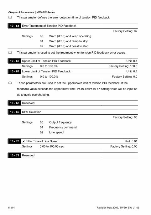
Chapter 5 Parameters|VFD-BW Series
5-114 Revision May 2009, BWE0, SW V1.05
This parameter defines the error detection time of tension PID feedback.
10 - 65 Error Treatment of Tension PID Feedback
Factory Setting: 02
Settings 00 Warn (rFbE) and keep operating
01 Warn (rFbE) and ramp to stop
02 Warn (rFbE) and coast to stop
This parameter is used to set the treatment when tension PID feedback error occurs.
10 - 66 Upper Limit of Tension PID Feedback Unit: 0.1
Settings 0.0 to 100.0% Factory Setting: 100.0
10 - 67 Lower Limit of Tension PID Feedback Unit: 0.1
Settings 0.0 to 100.0% Factory Setting: 0.0
These parameters are used to set the upper/lower limit of tension PID feedback. If the
feedback value exceeds the upper/lower limit, Pr.10-66/Pr.10-67 setting value will be input so
as to avoid overshooting.
10 - 68 Reserved
10 - 69 DFM Selection
Factory Setting: 00
Settings 00 Output frequency
01 Frequency command
02 Line speed
10 - 70 Filter Time of Line Speed Unit: 0.01
Settings 0.00 to 100.00 sec Factory Setting: 0.00
10 - 71 Reserved
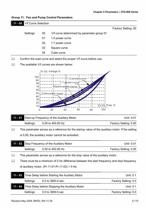
Chapter 5 Parameters|VFD-BW Series
Revision May 2009, BWE0, SW V1.05 5-115
Group 11: Fan and Pump Control Parameters
11 - 00 V/f Curve Selection
Factory Setting: 00
Settings 00 V/f curve determined by parameter group 01
01 1.5 power curve
02 1.7 power curve
03 Square curve
04 Cube curve
Confirm the load curve and select the proper V/f curve before use.
The available V/f curves are shown below:
Freq. %
0 20 40 60 80 100102030405060708090
100
01-02
01-01
1.5 power curve1.7 power curve
Square power curve
Cube power curve
Voltage %
11 - 01 Start-up Frequency of the Auxiliary Motor Unit: 0.01
Settings 0.00 to 400.00 Hz Factory Setting: 0.00
This parameter serves as a reference for the startup value of the auxiliary motor. If the setting
is 0.00, the auxiliary motor cannot be activated.
11 - 02 Stop Frequency of the Auxiliary Motor Unit: 0.01
Settings 0.00 to 400.00 Hz Factory Setting: 0.00
This parameter serves as a reference for the stop value of the auxiliary motor.
There must be a minimum of 5 Hz difference between the start frequency and stop frequency
of auxiliary motor. (Pr.11-01-Pr.11-02) > 5 Hz.
11 - 03 Time Delay before Starting the Auxiliary Motor Unit: 0.1
Settings 0.0 to 3600.0 sec Factory Setting: 0.0
11 - 04 Time Delay before Stopping the Auxiliary Motor Unit: 0.1
Settings 0.0 to 3600.0 sec Factory Setting: 0.0
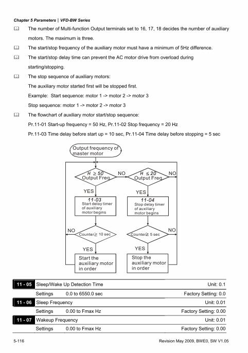
Chapter 5 Parameters|VFD-BW Series
5-116 Revision May 2009, BWE0, SW V1.05
The number of Multi-function Output terminals set to 16, 17, 18 decides the number of auxiliary
motors. The maximum is three.
The start/stop frequency of the auxiliary motor must have a minimum of 5Hz difference.
The start/stop delay time can prevent the AC motor drive from overload during
starting/stopping.
The stop sequence of auxiliary motors:
The auxiliary motor started first will be stopped first.
Example: Start sequence: motor 1 -> motor 2 -> motor 3
Stop sequence: motor 1 -> motor 2 -> motor 3
The flowchart of auxiliary motor start/stop sequence:
Pr.11-01 Start-up frequency = 50 Hz, Pr.11-02 Stop frequency = 20 Hz
Pr.11-03 Time delay before start up = 10 sec, Pr.11-04 Time delay before stopping = 5 sec
H 50
11-03
H 20
11-04
Output frequency ofmaster motor
Output Freq. Output Freq.NO NO
NONO
Start delay timerof auxiliarymotor begins
Stop delay timerof auxiliarymotor begins
Counter 10 sec Counter 5 sec
Start the auxiliary motorin order
Stop the auxiliary motorin order
YES YES
YES YES
11 - 05 Sleep/Wake Up Detection Time Unit: 0.1
Settings 0.0 to 6550.0 sec Factory Setting: 0.0
11 - 06 Sleep Frequency Unit: 0.01
Settings 0.00 to Fmax Hz Factory Setting: 0.00
11 - 07 Wakeup Frequency Unit: 0.01
Settings 0.00 to Fmax Hz Factory Setting: 0.00
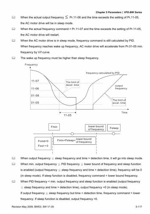
Chapter 5 Parameters|VFD-BW Series
Revision May 2009, BWE0, SW V1.05 5-117
When the actual output frequency ≤ Pr.11-06 and the time exceeds the setting of Pr.11-05,
the AC motor drive will be in sleep mode.
When the actual frequency command > Pr.11-07 and the time exceeds the setting of Pr.11-05,
the AC motor drive will restart.
When the AC motor drive is in sleep mode, frequency command is still calculated by PID.
When frequency reaches wake up frequency, AC motor drive will accelerate from Pr.01-05 min.
frequency by V/f curve.
The wake up frequency must be higher than sleep frequency.
11-07
11-06
01-08
01-05
11-05
Frequency
The limit of decel. time
frequency calculated by PID
outputfrequency
Time
The limit of accel. time
Fmin
Fsleep
Fcmd=0
Fout = 0
lower bound of frequency
Fmin<Fsleep< lower bound of frequency
When output frequency ≦ sleep frequency and time > detection time, it will go into sleep mode.
When min. output frequency ≦ PID frequency ≦ lower bound of frequency and sleep function
is enabled (output frequency ≦ sleep frequency and time > detection time), frequency will be 0
(in sleep mode). If sleep function is disabled, frequency command = lower bound frequency.
When PID frequency < min. output frequency and sleep function is enabled (output frequency
≦ sleep frequency and time > detection time), output frequency =0 (in sleep mode).
If output frequency ≦ sleep frequency but time < detection time, frequency command = lower
frequency. If sleep function is disabled, output frequency =0.

Chapter 5 Parameters|VFD-BW Series
5-118 Revision May 2009, BWE0, SW V1.05
This page intentionally left blank.
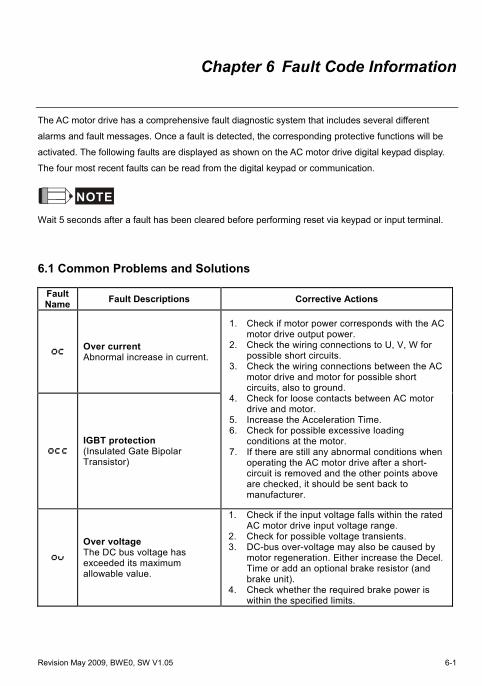
Revision May 2009, BWE0, SW V1.05 6-1
Chapter 6 Fault Code Information
The AC motor drive has a comprehensive fault diagnostic system that includes several different
alarms and fault messages. Once a fault is detected, the corresponding protective functions will be
activated. The following faults are displayed as shown on the AC motor drive digital keypad display.
The four most recent faults can be read from the digital keypad or communication.
NOTE
Wait 5 seconds after a fault has been cleared before performing reset via keypad or input terminal.
6.1 Common Problems and Solutions
Fault Name Fault Descriptions Corrective Actions
Over current Abnormal increase in current.
IGBT protection (Insulated Gate Bipolar Transistor)
1. Check if motor power corresponds with the AC motor drive output power.
2. Check the wiring connections to U, V, W for possible short circuits.
3. Check the wiring connections between the AC motor drive and motor for possible short circuits, also to ground.
4. Check for loose contacts between AC motor drive and motor.
5. Increase the Acceleration Time. 6. Check for possible excessive loading
conditions at the motor. 7. If there are still any abnormal conditions when
operating the AC motor drive after a short-circuit is removed and the other points above are checked, it should be sent back to manufacturer.
Over voltage The DC bus voltage has exceeded its maximum allowable value.
1. Check if the input voltage falls within the rated AC motor drive input voltage range.
2. Check for possible voltage transients. 3. DC-bus over-voltage may also be caused by
motor regeneration. Either increase the Decel. Time or add an optional brake resistor (and brake unit).
4. Check whether the required brake power is within the specified limits.
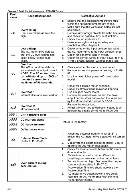
Chapter 6 Fault Code Information|VFD-BW Series
6-2 Revision May 2009, BWE0, SW V1.05
Fault Name Fault Descriptions Corrective Actions
Overheating Heat sink temperature is too high
1. Ensure that the ambient temperature falls within the specified temperature range.
2. Make sure that the ventilation holes are not obstructed.
3. Remove any foreign objects from the heatsinks and check for possible dirty heat sink fins.
4. Check the fan and clean it. 5. Provide enough spacing for adequate
ventilation. (See chapter 2)
Low voltage The AC motor drive detects that the DC bus voltage has fallen below its minimum value.
1. Check whether the input voltage falls within the AC motor drive rated input voltage range.
2. Check for abnormal load in motor. 3. Check for correct wiring of input power to R-S-
T (for 3-phase models) without phase loss.
Overload The AC motor drive detects excessive drive output current.NOTE: The AC motor drive can withstand up to 150% of the rated current for a maximum of 60 seconds.
1. Check whether the motor is overloaded. 2. Reduce torque compensation setting in Pr.07-
02. 3. Use the next higher power AC motor drive
model.
Overload 1 Internal electronic overload trip
1. Check for possible motor overload. 2. Check electronic thermal overload setting. 3. Use a higher power motor. 4. Reduce the current level so that the drive
output current does not exceed the value set by the Motor Rated Current Pr.07-00.
Overload 2 Motor overload.
1. Reduce the motor load. 2. Adjust the over-torque detection setting to an
appropriate setting (Pr.06-03 to Pr.06-05).
GFF hardware error
CC (current clamp)
OC hardware error
OV hardware error
Return to the factory.
External Base Block. (Refer to Pr. 08-06)
1. When the external input terminal (B.B) is active, the AC motor drive output will be turned off.
2. Deactivate the external input terminal (B.B) to operate the AC motor drive again.
Over-current during acceleration
1. Check for loose contacts between AC motor drive and motor.
2. Short-circuit at motor output: Check for possible poor insulation at the output lines.
3. Torque boost too high: Decrease the torque compensation setting in Pr.07-02.
4. Acceleration Time too short: Increase the Acceleration Time.
5. AC motor drive output power is too small: Replace the AC motor drive with the next higher power model.
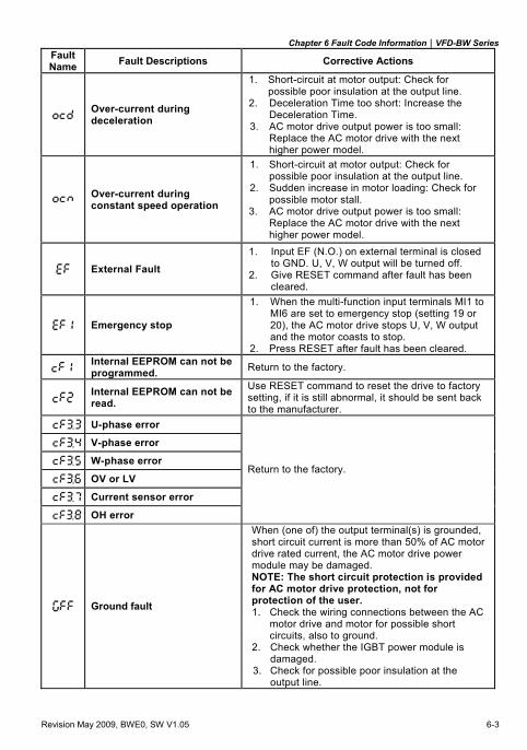
Chapter 6 Fault Code Information|VFD-BW Series
Revision May 2009, BWE0, SW V1.05 6-3
Fault Name Fault Descriptions Corrective Actions
Over-current during deceleration
1. Short-circuit at motor output: Check for possible poor insulation at the output line.
2. Deceleration Time too short: Increase the Deceleration Time.
3. AC motor drive output power is too small: Replace the AC motor drive with the next higher power model.
Over-current during constant speed operation
1. Short-circuit at motor output: Check for possible poor insulation at the output line.
2. Sudden increase in motor loading: Check for possible motor stall.
3. AC motor drive output power is too small: Replace the AC motor drive with the next higher power model.
External Fault 1. Input EF (N.O.) on external terminal is closed
to GND. U, V, W output will be turned off. 2. Give RESET command after fault has been
cleared.
Emergency stop
1. When the multi-function input terminals MI1 to MI6 are set to emergency stop (setting 19 or 20), the AC motor drive stops U, V, W output and the motor coasts to stop.
2. Press RESET after fault has been cleared.
Internal EEPROM can not be programmed. Return to the factory.
Internal EEPROM can not be read.
Use RESET command to reset the drive to factory setting, if it is still abnormal, it should be sent back to the manufacturer.
U-phase error
V-phase error
W-phase error
OV or LV
Current sensor error
OH error
Return to the factory.
Ground fault
When (one of) the output terminal(s) is grounded, short circuit current is more than 50% of AC motor drive rated current, the AC motor drive power module may be damaged. NOTE: The short circuit protection is provided for AC motor drive protection, not for protection of the user. 1. Check the wiring connections between the AC
motor drive and motor for possible short circuits, also to ground.
2. Check whether the IGBT power module is damaged.
3. Check for possible poor insulation at the output line.
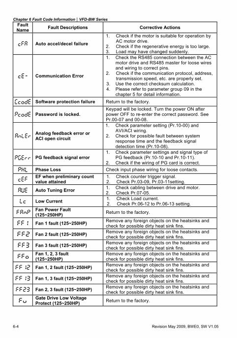
Chapter 6 Fault Code Information|VFD-BW Series
6-4 Revision May 2009, BWE0, SW V1.05
Fault Name Fault Descriptions Corrective Actions
Auto accel/decel failure 1. Check if the motor is suitable for operation by
AC motor drive. 2. Check if the regenerative energy is too large. 3. Load may have changed suddenly.
Communication Error
1. Check the RS485 connection between the AC motor drive and RS485 master for loose wires and wiring to correct pins.
2. Check if the communication protocol, address, transmission speed, etc. are properly set.
3. Use the correct checksum calculation. 4. Please refer to parameter group 09 in the
chapter 5 for detail information.
Software protection failure Return to the factory.
Password is locked. Keypad will be locked. Turn the power ON after power OFF to re-enter the correct password. See Pr.00-07 and 00-08.
Analog feedback error or ACI open circuit
1. Check parameter setting (Pr.10-00) and AVI/ACI wiring.
2. Check for possible fault between system response time and the feedback signal detection time (Pr.10-08).
PG feedback signal error 1. Check parameter settings and signal type of
PG feedback (Pr.10-10 and Pr.10-11). 2. Check if the wiring of PG card is correct.
Phase Loss Check input phase wiring for loose contacts.
EF when preliminary count value attained
1. Check counter trigger signal. 2. Check Pr.03-09, Pr.03-11setting.
Auto Tuning Error 1. Check cabling between drive and motor. 2. Check Pr.07-05.
Low Current 1. Check Load current. 2. Check Pr.06-12 to Pr.06-13 setting.
Fan Power Fault (125~250HP) Return to the factory.
Fan 1 fault (125~250HP) Remove any foreign objects on the heatsinks and check for possible dirty heat sink fins.
Fan 2 fault (125~250HP) Remove any foreign objects on the heatsinks and check for possible dirty heat sink fins.
Fan 3 fault (125~250HP) Remove any foreign objects on the heatsinks and check for possible dirty heat sink fins.
Fan 1, 2, 3 fault (125~250HP)
Remove any foreign objects on the heatsinks and check for possible dirty heat sink fins.
Fan 1, 2 fault (125~250HP) Remove any foreign objects on the heatsinks and check for possible dirty heat sink fins.
Fan 1, 3 fault (125~250HP) Remove any foreign objects on the heatsinks and check for possible dirty heat sink fins.
Fan 2, 3 fault (125~250HP) Remove any foreign objects on the heatsinks and check for possible dirty heat sink fins.
Gate Drive Low Voltage Protect (125~250HP) Return to the factory.
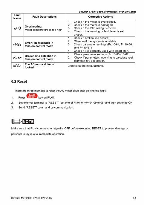
Chapter 6 Fault Code Information|VFD-BW Series
Revision May 2009, BWE0, SW V1.05 6-5
Fault Name Fault Descriptions Corrective Actions
Overheating Motor temperature is too high
1. Check if the motor is overloaded. 2. Check if the motor is damaged. 3. Check if the PTC wiring is correct. 4. Check if the warning or fault level is set
proper.
Error PID feedback in tension control mode
1. Check if broken line occurs. 2. Observe if the system is unstable. 3. Check parameter settings (Pr.10-64, Pr.10-66,
and Pr.10-67). 4. Check if it is correctly used with smart start.
Broken line detection in tension control mode
1. Check parameter settings (Pr.10-60~10-62). 2. Check if parameters involving to calculate reel
diameter are set proper.
The AC motor drive is locked. Contact to the manufacturer.
6.2 Reset
There are three methods to reset the AC motor drive after solving the fault:
1. Press RESETSTOP
key on PU01.
2. Set external terminal to “RESET” (set one of Pr.04-04~Pr.04-09 to 05) and then set to be ON.
3. Send “RESET” command by communication.
NOTE
Make sure that RUN command or signal is OFF before executing RESET to prevent damage or
personal injury due to immediate operation.

Chapter 6 Fault Code Information|VFD-BW Series
6-6 Revision May 2009, BWE0, SW V1.05
This page intentionally left blank.
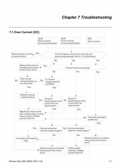
Revision May 2009, BWE0, SW V1.05 7-1
Chapter 7 Troubleshooting
7.1 Over Current (OC)
ocA ocd OC
Over-current during acceleration
Over-current during dec eleration
Over current
Check if there i s any between the U, V, W and motor
short circuits and grounding
Yes
No No No
No No No
Yes
YesYes
Remove shor t cir cuit or ground fault
Reduce the load orincrease the powerof AC motor dr ive
NoNoCan torquecompensation be reduced?
Reduce torque compensation
Is torquecompensation suitable?
No No
No
NoNo
Yes Yes
Yes
YesYes
Maybe AC motor drivehas malfunc ti on or errordue to noise. Please contact DELTA.
Can acc el eration time be made longer?
Can deceleration t ime be made longer?
Reduc e load or inc reasethe power of AC motordriv e
Check brakemethod. Please contact DELTA
Reduce load or inc reasethe power of AC motordriv e
Has l oad changedsuddenly?
Check if accelerati on t imeis too short by load iner ti a.
Check if deceleration timeis too short by load iner ti a.
Increase accel/decel t ime
Check if load i s too large
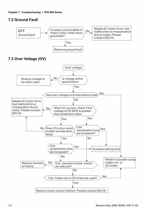
Chapter 7 Troubleshooting |VFD-BW Series
7-2 Revision May 2009, BWE0, SW V1.05
7.2 Ground Fault
GFFGround fault
No
Yes
Is output circuit(cable or motor) of AC motor drive grounded?
Remove ground fault
Maybe AC motor drive has malfunction or misoperationdue to noise. Please contact DELTA.
7.3 Over Voltage (OV)
Over voltage
Yes
No
Yes
No
No
No
Is voltage within specification
Reduce voltage tobe within spec.
Has over-voltage occurred without load
Maybe AC motor drivehas malfunction or misoperation due tonoise. Please contactDELTA.
Yes Yes
Yes
Yes
Yes
Yes
No
No
No
No
No
When OV occurs, check if the voltage of DC BUS is greaterthan protection value
Does OV occur when sudden accelerationstops
Can deceleration time be increased?
Increase setting timeCan acceleration time be increased?
Reduce moment of inertia
Can moment of load inertia be reduced?
Can brake unit or DC brake be used?
Need to check control method. Please contact DELTA.
Need to consider usingbrake unit or DC brake
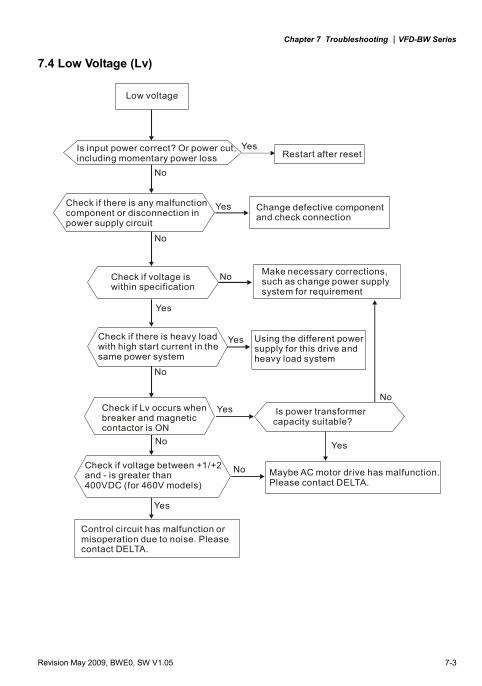
Chapter 7 Troubleshooting |VFD-BW Series
Revision May 2009, BWE0, SW V1.05 7-3
7.4 Low Voltage (Lv)
Low voltage
Is input power correct? Or power cut, including momentary power loss
Yes
Yes
Yes
Yes
Yes
Yes
No
No
No
No
No
No
No
Restart after reset
Check if there is any malfunctioncomponent in power supply circuit
or disconnection Change defective componentand check connection
Check if voltage is within specification
Make necessary corrections, such as change power supply system for requirement
Check if there is heavy loadwith high start current in thesame power system
Check if Lv occurs when breaker and magnetic contactor is ON
Is transformer power capacity suitable?
Check if voltage between +1/+2 and - is greater than 400VDC (for 460V models)
Maybe AC motor drive has malfunction.Please contact DELTA.
Control circuit has malfunction or misoperation due to noise. Pleasecontact DELTA.
Yes Using the different powersupply for this drive and heavy load system
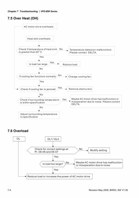
Chapter 7 Troubleshooting |VFD-BW Series
7-4 Revision May 2009, BWE0, SW V1.05
7.5 Over Heat (OH)
AC motor driv e overheats
Heat sink overheats
Check if temperature of heat si nkis greater than 90 OC
No
No
No
Yes
Yes
Yes
Yes
Yes
No
Reduce load
No Temperature detection mal functions.Please contac t DELTA.
If cooling fan functions normally Change cooling fan
Check if cooling fan is jammed Remove obstruc tion
Check if sur rounding temperatureis withi n specif ication
Adjust surrounding temperatureto speci fic ati on
Maybe AC motor drive has malfunction or misoperation due to noise. Pleas e contactDELTA.
Is load too large
7.6 Overload
OL1/ OL2OL
Reduce load or increase the power of AC motor drive
Check for correct settings at Pr. 06-06 and 06-07
Yes
Yes
No
No Modify setting
Is load too large? Maybe AC motor drive has malfunctionor misoperation due to noise.
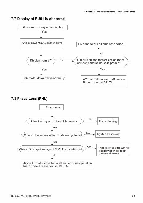
Chapter 7 Troubleshooting |VFD-BW Series
Revision May 2009, BWE0, SW V1.05 7-5
7.7 Display of PU01 is Abnormal
Abnormal display or no display
Cycle power to AC motor drive
No
Yes
Yes Yes
No
Display normal?
AC motor drive works normally
Fix connector and eliminate noise
Check if all connectors are connect correctly and no noise is present
AC motor drive has malfunction.Please contact DELTA.
7.8 Phase Loss (PHL)
Phase loss
No
No
Yes
Yes
Check wiring at R, S and T terminals Correct wiring
Check if the screws of terminals are tightenedNo Tighten all screws
Yes Please check the wiring and power system for abnormal power
Maybe AC motor drive has malfunction or misoperationdue to noise. Please contact DELTA.
Check if the input voltage of R, S, T is unbalanced
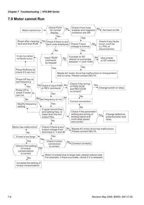
Chapter 7 Troubleshooting |VFD-BW Series
7-6 Revision May 2009, BWE0, SW V1.05
7.9 Motor cannot Run
Motor cannot run Check PU01 for normal display
No No
No
No
No No
NoNo
No No No No
No
No
No
Check if non-fuse breaker and magneticcontactor are ON
YesYes
Yes
YesYes
Yes
Yes
YesYes
Yes
Yes
Set them to ON
Reset after clearingfault and then RUN
Check if there is any fault code displayed Check if input
voltage is normal
Check if any faults occur, such asLv, PHL or disconnection
Input "RUN" command by keypad
It can run whenno faults occur
If jumper or DC reactor is connectedbetween +1 and +2/B1
Use jumperor DC reactor
Press RUN key to check if it can run Maybe AC motor drive has malfunction or misoperation
due to noise. Please contact DELTA.Press UP key to set frequency
Yes
Modify frequencysetting
Check if input FWDor REV command
Check if the wiring of FWD-DCM and REV-DCM is correct?
YesChange switch or relay
Set frequency or not
Press UP to check if motor can run
Correct connection
Check if the parameter setting and wiring of analog signal andmulti-step speed are correct
No
Motor has malfunction No Maybe AC motor drive has malfunction.Please contact DELTA.
Check if there is any output voltage from terminals U, V and W
Check if motor connection is correct
NoConnect correctly
Check if the setting of torque compensation is correct
Increase the setting oftorque compensation
Motor is locked due to large load, please reduce load.For example, if there is a brake, check if it is released.
If load is too large
if upper bound freq. and setting freq. is lower than the min.output freq.
Yes Change defectivepotentiometer and relay
Yes
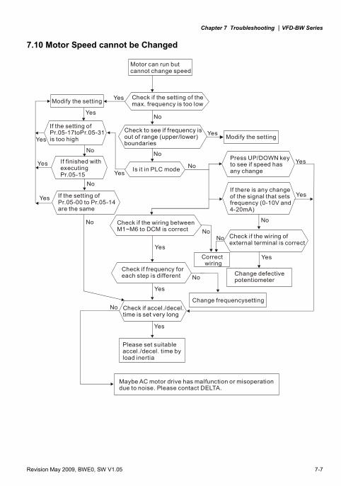
Chapter 7 Troubleshooting |VFD-BW Series
Revision May 2009, BWE0, SW V1.05 7-7
7.10 Motor Speed cannot be Changed
Motor can run butcannot change speed
Yes
Yes
Yes
Yes
Yes
Yes
Yes
Yes
Yes
Yes
No
No
No
No
NoNo
No
No
No
No
Check if the setting of the max. frequency is too low
Check to see if frequency is out of range (upper/lower) boundaries
Modify the setting
Modify the settingYes
NoYes
If the setting of Pr.05-17toPr.05-31is too high Yes
If finished with executingPr.05-15
If the setting ofPr.05-00 to Pr.05-14 are the same
Is it in PLC mode
Press UP/DOWN keyto see if speed has any change
If there is any changeof the signal that setsfrequency (0-10V and4-20mA)
Check if the wiring betweenM1~M6 to DCM is correct
Correct wiring
Check if frequency for each step is different
Check if the wiring of external terminal is correct
Change frequencysettingCheck if accel./decel. time is set very long
Please set suitableaccel./decel. time byload inertia
Maybe AC motor drive has malfunction or misoperationdue to noise. Please contact DELTA.
Change defectivepotentiometer
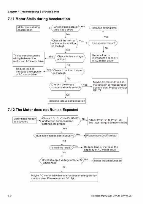
Chapter 7 Troubleshooting |VFD-BW Series
7-8 Revision May 2009, BWE0, SW V1.05
7.11 Motor Stalls during Acceleration
Motor stalls during acceleration
Check if accelerationtime is too short
Yes
Yes
Yes
Yes
No
NoNo
No
No
No
Increase setting time
YesUse special motor?
Reduce load orincrease the capacityof AC motor drive
Check if the inertia of the motor and load is too high
Check for low voltage at input
Check if the load torqueis too high
YesMaybe AC motor drive hasmalfunction or misoperationdue to noise. Please contactDELTA
Increase torque compensation
Check if the torque compensation is suitable
Thicken or shorten the wiring between the motor and AC motor drive
Reduce load orincrease the capacityof AC motor drive
7.12 The Motor does not Run as Expected
Check if Pr. 01-01 to Pr. 01-06 and torque compensation settings are proper
No
Yes
Yes
Yes
Yes
No
No
No
Adjust Pr.01-01 to Pr.01-06and lower torque compensation
Run in low speed continuously?
Is load too large?
Please use specific motor
Reduce load or increase the capacity of AC motor drive
Check if output voltage of U, V, W is balanced
Motor has malfunction
Maybe AC motor drive has malfunction or misoperationdue to noise. Please contact DELTA.
Motor does not runas expected
Chapter 7 Troubleshooting |VFD-BW Series
Revision May 2009, BWE0, SW V1.05 7-9
7.13 Electromagnetic/Induction Noise
There are many noises surround the AC motor drives and invade it by radiation or power circuit. It
may cause the misoperation of control circuit and even damage the AC motor drive. Of course, that
is a solution to increase the noise tolerance of AC motor drive. But it is not the best one due to the
limit. Therefore, solve it from the outside as following will be the best.
1. Add surge suppressor on the relay or contact to suppress switching surge between ON/OFF.
2. Shorten the wiring length of the control circuit or serial circuit and separate from the main AC
circuit wiring.
3. Comply with the wiring regulation for those shielded wire and use isolation amplifier for long
wire length.
4. The grounding terminal should comply with the local regulation and ground independently, i.e.
not to have common ground with electric welding machine and power equipment.
5. Connect a noise filter at the input terminal of the AC motor drive to prevent noise from power
circuit.
In a word, three-level solutions for electromagnetic noise are “no product”, “no spread” and “no
receive”.
7.14 Environmental Condition
Since the AC motor drive is an electronic device, you should comply with the environmental
condition stated in the Chapter 2.1. The following steps should also be followed. 1. To prevent vibration, anti-vibration spacer is the last choice. The vibration tolerance must be
within the specification. The vibration effect is equal to the mechanical stress and it cannot
occur frequently, continuously or repeatedly to prevent damaging to the AC motor drive.
2. Store in a clean and dry location free from corrosive fumes/dust to prevent corrosion and poor
contacts. It also may cause short by low insulation in a humid location. The solution is to use
both paint and dust-proof. For particular occasion, use the enclosure with whole-seal structure.
3. The surrounding temperature should be within the specification. Too high or low temperature
will affect the lifetime and reliability. For semiconductor components, damage will occur once
any specification is out of range. Therefore, it is necessary to clean and periodical check for the
air cleaner and cooling fan besides having cooler and sunshade. In addition, the microcomputer
may not work in extreme low temperature and needs to have heater.
4. Store within a relative humidity range of 0% to 90% and non-condensing environment. Do not
turn off the air conditioner and have exsiccator for it.
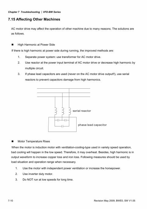
Chapter 7 Troubleshooting |VFD-BW Series
7-10 Revision May 2009, BWE0, SW V1.05
7.15 Affecting Other Machines
AC motor drive may affect the operation of other machine due to many reasons. The solutions are
as follows.
High Harmonic at Power Side
If there is high harmonic at power side during running, the improved methods are:
1. Separate power system: use transformer for AC motor drive.
2. Use reactor at the power input terminal of AC motor drive or decrease high harmonic by
multiple circuit.
3. If phase lead capacitors are used (never on the AC motor drive output!!), use serial
reactors to prevent capacitors damage from high harmonics.
serial reactor
phase lead capacitor
Motor Temperature Rises
When the motor is induction motor with ventilation-cooling-type used in variety speed operation,
bad cooling will happen in the low speed. Therefore, it may overheat. Besides, high harmonic is in
output waveform to increase copper loss and iron loss. Following measures should be used by
load situation and operation range when necessary.
1. Use the motor with independent power ventilation or increase the horsepower.
2. Use inverter duty motor.
3. Do NOT run at low speeds for long time.
Revision May 2009, BWE0, SW V1.05 8-1
Chapter 8 Maintenance and Inspections
Modern AC motor drives are based on solid state electronics technology. Preventive maintenance is
required to operate this AC motor drive in its optimal condition, and to ensure a long life. It is
recommended to have a check-up of the AC motor drive performed by a qualified technician.
Daily Inspection:
Basic check-up items to detect if there were any abnormalities during operation are:
1. Whether the motors are operating as expected.
2. Whether the installation environment is abnormal.
3. Whether the cooling system is operating as expected.
4. Whether any irregular vibration or sound occurred during operation.
5. Whether the motors are overheating during operation.
6. Always check the input voltage of the AC drive with a Voltmeter.
Periodic Inspection: Before the check-up, always turn off the AC input power and remove the cover. Wait at least 10
minutes after all display lamps have gone out, and then confirm that the capacitors have fully
discharged by measuring the voltage between +1/+2 and -. The voltage between +1/+2 and - should
be less than 25VDC.
DANGER!
1. Disconnect AC power before processing!
2. Only qualified personnel can install, wire and maintain AC motor drives. Please take off any
metal objects, such as watches and rings, before operation. And only insulated tools are
allowed.
3. Never reassemble internal components or wiring.
4. Prevent electric shocks.
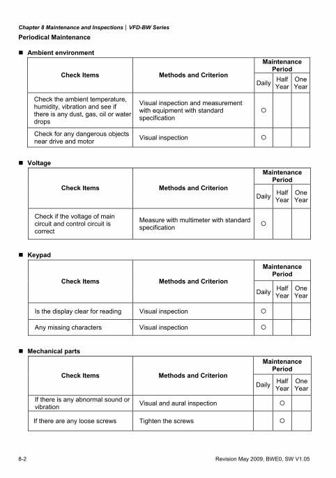
Chapter 8 Maintenance and Inspections|VFD-BW Series
8-2 Revision May 2009, BWE0, SW V1.05
Periodical Maintenance
Ambient environment Maintenance
Period Check Items Methods and Criterion
Daily Half Year
One Year
Check the ambient temperature, humidity, vibration and see if there is any dust, gas, oil or water drops
Visual inspection and measurement with equipment with standard specification
Check for any dangerous objects near drive and motor Visual inspection
Voltage Maintenance
Period Check Items Methods and Criterion
Daily Half Year
One Year
Check if the voltage of main circuit and control circuit is correct
Measure with multimeter with standard specification
Keypad Maintenance
Period Check Items Methods and Criterion
Daily Half Year
One Year
Is the display clear for reading Visual inspection
Any missing characters Visual inspection
Mechanical parts Maintenance
Period Check Items Methods and Criterion
Daily Half Year
One Year
If there is any abnormal sound or vibration Visual and aural inspection
If there are any loose screws Tighten the screws
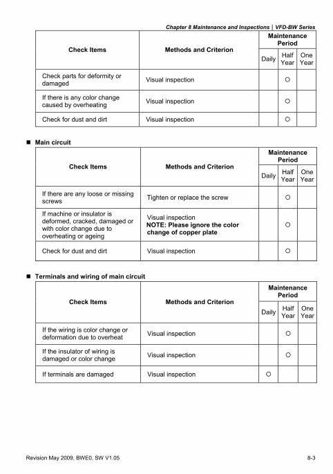
Chapter 8 Maintenance and Inspections|VFD-BW Series
Revision May 2009, BWE0, SW V1.05 8-3
Maintenance Period
Check Items Methods and Criterion Daily Half
YearOne Year
Check parts for deformity or damaged Visual inspection
If there is any color change caused by overheating Visual inspection
Check for dust and dirt Visual inspection
Main circuit Maintenance
Period Check Items Methods and Criterion
Daily Half Year
One Year
If there are any loose or missing screws Tighten or replace the screw
If machine or insulator is deformed, cracked, damaged or with color change due to overheating or ageing
Visual inspection NOTE: Please ignore the color change of copper plate
Check for dust and dirt Visual inspection
Terminals and wiring of main circuit Maintenance
Period Check Items Methods and Criterion
Daily Half Year
One Year
If the wiring is color change or deformation due to overheat Visual inspection
If the insulator of wiring is damaged or color change Visual inspection
If terminals are damaged Visual inspection
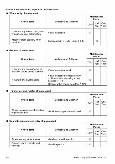
Chapter 8 Maintenance and Inspections|VFD-BW Series
8-4 Revision May 2009, BWE0, SW V1.05
DC capacity of main circuit Maintenance
Period Check Items Methods and Criterion
Daily Half Year
One Year
If there is any leak of liquid, color change, crack or deformation Visual inspection
Measure static capacity when required Static capacity ≥ initial value X 0.85
Resistor of main circuit Maintenance
Period Check Items Methods and Criterion
Daily Half Year
One Year
If there is any peculiar smell or insulator cracks due to overheat Visual inspection, smell
If there is any disconnection
Visual inspection or measure with multimeter after removing wiring between +1/+2 ~ - Resistor value should be within ± 10%
Transformer and reactor of main circuit Maintenance
Period Check Items Methods and Criterion
Daily Half Year
One Year
If there is any abnormal vibration or peculiar smell Visual, aural inspection and smell
Magnetic contactor and relay of main circuit Maintenance
Period Check Items Methods and Criterion
Daily Half Year
One Year
If there are any loose screws Visual and aural inspection
Check to see if contacts work correctly Visual inspection
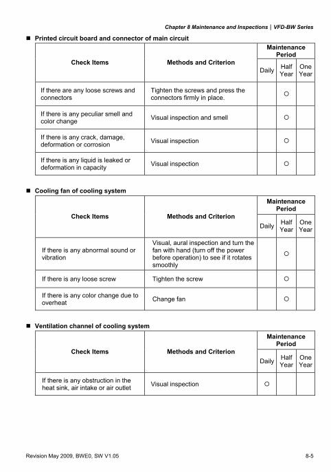
Chapter 8 Maintenance and Inspections|VFD-BW Series
Revision May 2009, BWE0, SW V1.05 8-5
Printed circuit board and connector of main circuit Maintenance
Period Check Items Methods and Criterion
Daily Half Year
One Year
If there are any loose screws and connectors
Tighten the screws and press the connectors firmly in place.
If there is any peculiar smell and color change Visual inspection and smell
If there is any crack, damage, deformation or corrosion Visual inspection
If there is any liquid is leaked or deformation in capacity Visual inspection
Cooling fan of cooling system Maintenance
Period Check Items Methods and Criterion
Daily Half Year
One Year
If there is any abnormal sound or vibration
Visual, aural inspection and turn the fan with hand (turn off the power before operation) to see if it rotates smoothly
If there is any loose screw Tighten the screw
If there is any color change due to overheat Change fan
Ventilation channel of cooling system Maintenance
Period Check Items Methods and Criterion
Daily Half Year
One Year
If there is any obstruction in the heat sink, air intake or air outlet Visual inspection

Chapter 8 Maintenance and Inspections|VFD-BW Series
8-6 Revision May 2009, BWE0, SW V1.05
This page intentionally left blank.
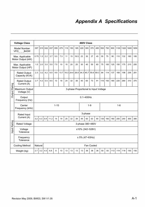
Revision May 2009, BWE0, SW V1.05 A-1
Appendix A Specifications
Voltage Class 460V Class
Model Number VFD_ _ _B43W
007 015 022 037 055 075 110 150 185 220 300 370 450 550 750 900 1100 1320 1600 1850
Max. Applicable Motor Output (kW)
0.75 1.5 2.2 3.7 5.5 7.5 11 15 18.5 22 30 37 45 55 75 90 110 132 160 185
Max. Applicable Motor Output (HP)
1.0 2.0 3.0 5.0 7.5 10 15 20 25 30 40 50 60 75 100 125 150 175 215 250
Rated Output Capacity (KVA)
2.3 3.2 4.2 6.5 9.9 13.7 18.3 24.4 28.9 34.3 45.7 55.6 69.3 84 114 137 168 198 236 281
Rated Output Current (A)
2.7 4.2 5.5 8.5 13 18 24 32 38 45 60 73 91 110 150 180 220 260 310 370
Maximum Output Voltage (V)
3-phase Proportional to Input Voltage
Output Frequency (Hz)
0.1~400Hz Out
put R
atin
g
Carrier Frequency (kHz)
1-15 1-9 1-6
3-phase Rated Input Current (A) 3.2 4.3 5.9 11.2 14 19 25 32 39 49 60 63 90 130 160 180 200 240 300 380
Rated Voltage 3-phase 380~480V
Voltage Tolerance
±10% (342~528V)
Inpu
t Rat
ing
Frequency Tolerance
± 5% (47~63Hz)
Cooling Method Natural Fan Cooled
Weight (kg) 2.7 3.2 4.5 6.8 8 10 13 13 13 13 36 36 36 50 50 113 119 119 150 150
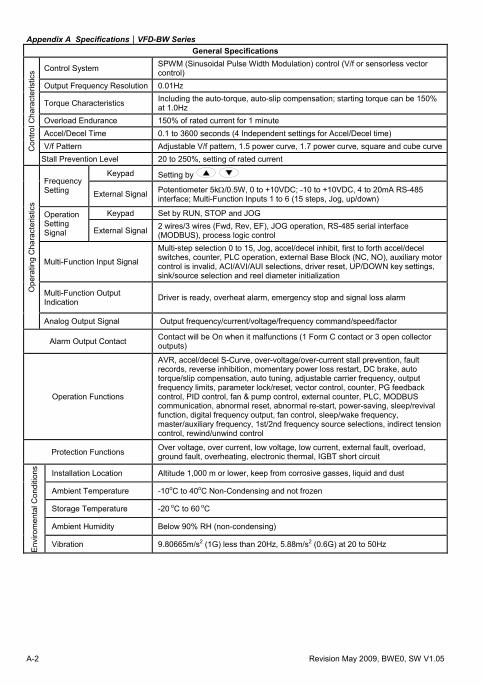
Appendix A Specifications|VFD-BW Series
A-2 Revision May 2009, BWE0, SW V1.05
General Specifications
Control System SPWM (Sinusoidal Pulse Width Modulation) control (V/f or sensorless vector control)
Output Frequency Resolution 0.01Hz
Torque Characteristics Including the auto-torque, auto-slip compensation; starting torque can be 150% at 1.0Hz
Overload Endurance 150% of rated current for 1 minute Accel/Decel Time 0.1 to 3600 seconds (4 Independent settings for Accel/Decel time) V/f Pattern Adjustable V/f pattern, 1.5 power curve, 1.7 power curve, square and cube curveC
ontro
l Cha
ract
eris
tics
Stall Prevention Level 20 to 250%, setting of rated current
Keypad Setting by Frequency Setting External Signal Potentiometer 5kΩ/0.5W, 0 to +10VDC; -10 to +10VDC, 4 to 20mA RS-485
interface; Multi-Function Inputs 1 to 6 (15 steps, Jog, up/down)
Keypad Set by RUN, STOP and JOG Operation Setting Signal External Signal 2 wires/3 wires (Fwd, Rev, EF), JOG operation, RS-485 serial interface
(MODBUS), process logic control
Multi-Function Input Signal
Multi-step selection 0 to 15, Jog, accel/decel inhibit, first to forth accel/decel switches, counter, PLC operation, external Base Block (NC, NO), auxiliary motor control is invalid, ACI/AVI/AUI selections, driver reset, UP/DOWN key settings, sink/source selection and reel diameter initialization
Multi-Function Output Indication Driver is ready, overheat alarm, emergency stop and signal loss alarm
Ope
ratin
g C
hara
cter
istic
s
Analog Output Signal Output frequency/current/voltage/frequency command/speed/factor
Alarm Output Contact Contact will be On when it malfunctions (1 Form C contact or 3 open collector outputs)
Operation Functions
AVR, accel/decel S-Curve, over-voltage/over-current stall prevention, fault records, reverse inhibition, momentary power loss restart, DC brake, auto torque/slip compensation, auto tuning, adjustable carrier frequency, output frequency limits, parameter lock/reset, vector control, counter, PG feedback control, PID control, fan & pump control, external counter, PLC, MODBUS communication, abnormal reset, abnormal re-start, power-saving, sleep/revival function, digital frequency output, fan control, sleep/wake frequency, master/auxiliary frequency, 1st/2nd frequency source selections, indirect tension control, rewind/unwind control
Protection Functions Over voltage, over current, low voltage, low current, external fault, overload, ground fault, overheating, electronic thermal, IGBT short circuit
Installation Location Altitude 1,000 m or lower, keep from corrosive gasses, liquid and dust
Ambient Temperature -10oC to 40oC Non-Condensing and not frozen
Storage Temperature -20 oC to 60 oC
Ambient Humidity Below 90% RH (non-condensing)
Env
irom
enta
l Con
ditio
ns
Vibration 9.80665m/s2 (1G) less than 20Hz, 5.88m/s2 (0.6G) at 20 to 50Hz
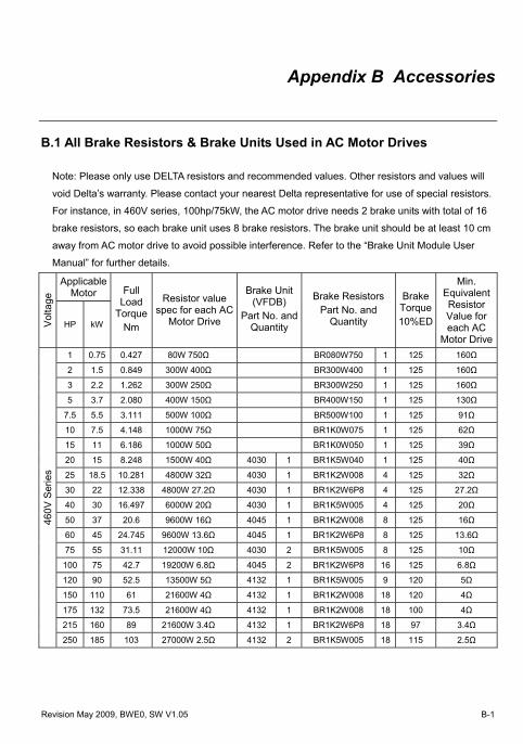
Revision May 2009, BWE0, SW V1.05 B-1
Appendix B Accessories
B.1 All Brake Resistors & Brake Units Used in AC Motor Drives
Note: Please only use DELTA resistors and recommended values. Other resistors and values will
void Delta’s warranty. Please contact your nearest Delta representative for use of special resistors.
For instance, in 460V series, 100hp/75kW, the AC motor drive needs 2 brake units with total of 16
brake resistors, so each brake unit uses 8 brake resistors. The brake unit should be at least 10 cm
away from AC motor drive to avoid possible interference. Refer to the “Brake Unit Module User
Manual” for further details.
Applicable Motor
Vol
tage
HP kW
Full Load
Torque Nm
Resistor value spec for each AC
Motor Drive
Brake Unit (VFDB)
Part No. and Quantity
Brake ResistorsPart No. and
Quantity
Brake Torque 10%ED
Min. Equivalent Resistor Value for each AC
Motor Drive1 0.75 0.427 80W 750Ω BR080W750 1 125 160Ω
2 1.5 0.849 300W 400Ω BR300W400 1 125 160Ω
3 2.2 1.262 300W 250Ω BR300W250 1 125 160Ω
5 3.7 2.080 400W 150Ω BR400W150 1 125 130Ω
7.5 5.5 3.111 500W 100Ω BR500W100 1 125 91Ω
10 7.5 4.148 1000W 75Ω BR1K0W075 1 125 62Ω
15 11 6.186 1000W 50Ω BR1K0W050 1 125 39Ω
20 15 8.248 1500W 40Ω 4030 1 BR1K5W040 1 125 40Ω
25 18.5 10.281 4800W 32Ω 4030 1 BR1K2W008 4 125 32Ω
30 22 12.338 4800W 27.2Ω 4030 1 BR1K2W6P8 4 125 27.2Ω
40 30 16.497 6000W 20Ω 4030 1 BR1K5W005 4 125 20Ω
50 37 20.6 9600W 16Ω 4045 1 BR1K2W008 8 125 16Ω
60 45 24.745 9600W 13.6Ω 4045 1 BR1K2W6P8 8 125 13.6Ω
75 55 31.11 12000W 10Ω 4030 2 BR1K5W005 8 125 10Ω
100 75 42.7 19200W 6.8Ω 4045 2 BR1K2W6P8 16 125 6.8Ω
120 90 52.5 13500W 5Ω 4132 1 BR1K5W005 9 120 5Ω
150 110 61 21600W 4Ω 4132 1 BR1K2W008 18 120 4Ω
175 132 73.5 21600W 4Ω 4132 1 BR1K2W008 18 100 4Ω
215 160 89 21600W 3.4Ω 4132 1 BR1K2W6P8 18 97 3.4Ω
460V
Ser
ies
250 185 103 27000W 2.5Ω 4132 2 BR1K5W005 18 115 2.5Ω
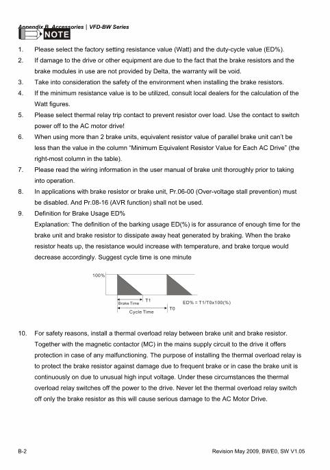
Appendix B Accessories|VFD-BW Series
B-2 Revision May 2009, BWE0, SW V1.05
NOTE
1. Please select the factory setting resistance value (Watt) and the duty-cycle value (ED%).
2. If damage to the drive or other equipment are due to the fact that the brake resistors and the
brake modules in use are not provided by Delta, the warranty will be void.
3. Take into consideration the safety of the environment when installing the brake resistors.
4. If the minimum resistance value is to be utilized, consult local dealers for the calculation of the
Watt figures.
5. Please select thermal relay trip contact to prevent resistor over load. Use the contact to switch
power off to the AC motor drive!
6. When using more than 2 brake units, equivalent resistor value of parallel brake unit can’t be
less than the value in the column “Minimum Equivalent Resistor Value for Each AC Drive” (the
right-most column in the table).
7. Please read the wiring information in the user manual of brake unit thoroughly prior to taking
into operation.
8. In applications with brake resistor or brake unit, Pr.06-00 (Over-voltage stall prevention) must
be disabled. And Pr.08-16 (AVR function) shall not be used.
9. Definition for Brake Usage ED%
Explanation: The definition of the barking usage ED(%) is for assurance of enough time for the
brake unit and brake resistor to dissipate away heat generated by braking. When the brake
resistor heats up, the resistance would increase with temperature, and brake torque would
decrease accordingly. Suggest cycle time is one minute
100%
T0
T1Brake Time
Cycle Time
ED% = T1/T0x100(%)
10. For safety reasons, install a thermal overload relay between brake unit and brake resistor.
Together with the magnetic contactor (MC) in the mains supply circuit to the drive it offers
protection in case of any malfunctioning. The purpose of installing the thermal overload relay is
to protect the brake resistor against damage due to frequent brake or in case the brake unit is
continuously on due to unusual high input voltage. Under these circumstances the thermal
overload relay switches off the power to the drive. Never let the thermal overload relay switch
off only the brake resistor as this will cause serious damage to the AC Motor Drive.
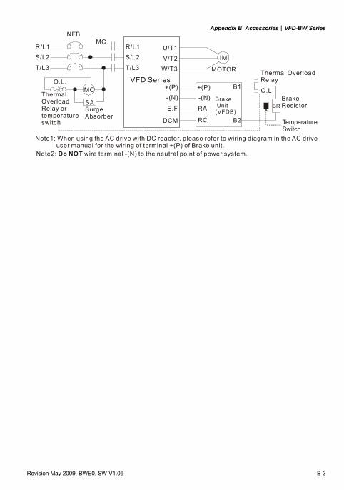
Appendix B Accessories|VFD-BW Series
Revision May 2009, BWE0, SW V1.05 B-3
R/L1S/L2
T/L3
NFBMC
VFD SeriesMOTOR
O.L.
U/T1
V/T2W/T3
+ P- N( )( )
B1
B2
SA
R/L1S/L2
T/L3
MC
IM
BR
O.L.ThermalOverloadRelay ortemperatureswitch
SurgeAbsorber
Thermal OverloadRelay
BrakeResistor
Brake Unit(VFDB)
+ P- N( )( )
Note1: When using the AC drive with DC reactor, please refer to wiring diagram in the AC drive user manual for the wiring of terminal +(P) of Brake unit. Note2: wire terminal -(N) to the neutral point of power system.Do NOT
TemperatureSwitch
E.F
DCM
RA
RC
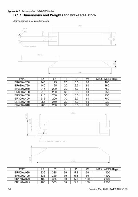
Appendix B Accessories|VFD-BW Series
B-4 Revision May 2009, BWE0, SW V1.05
B.1.1 Dimensions and Weights for Brake Resistors (Dimensions are in millimeter)
TYPE L1 L2 H D W MAX. WEIGHT(g) BR080W200 140 125 20 5.3 60 160 BR080W750 140 125 20 5.3 60 160 BR300W070 215 200 30 5.3 60 750 BR300W100 215 200 30 5.3 60 750 BR300W250 215 200 30 5.3 60 750 BR300W400 215 200 30 5.3 60 750 BR400W150 265 250 30 5.3 60 930 BR400W040 265 250 30 5.3 60 930
TYPE L1 L2 H D W MAX. WEIGHT(g) BR500W030 335 320 30 5.3 60 1100 BR500W100 335 320 30 5.3 60 1100 BR1K0W020 400 385 50 5.3 100 2800 BR1K0W075 400 385 50 5.3 100 2800
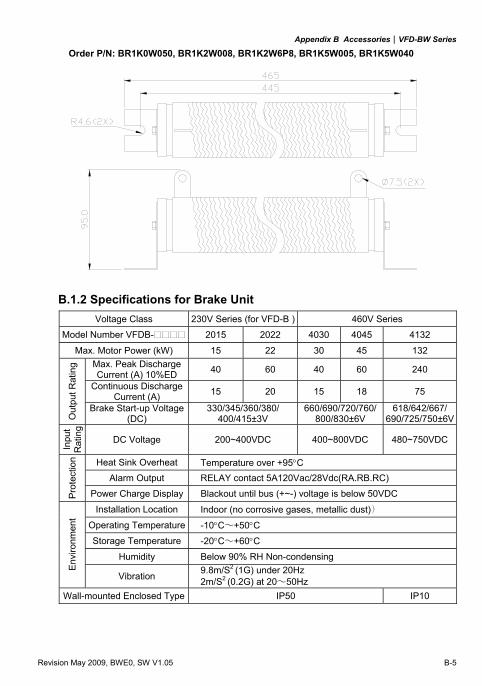
Appendix B Accessories|VFD-BW Series
Revision May 2009, BWE0, SW V1.05 B-5
Order P/N: BR1K0W050, BR1K2W008, BR1K2W6P8, BR1K5W005, BR1K5W040
B.1.2 Specifications for Brake Unit Voltage Class 230V Series (for VFD-B ) 460V Series
Model Number VFDB- 2015 2022 4030 4045 4132
Max. Motor Power (kW) 15 22 30 45 132 Max. Peak Discharge Current (A) 10%ED 40 60 40 60 240
Continuous Discharge Current (A) 15 20 15 18 75
Out
put R
atin
g
Brake Start-up Voltage (DC)
330/345/360/380/ 400/415±3V
660/690/720/760/800/830±6V
618/642/667/690/725/750±6V
Inpu
t R
atin
g
DC Voltage 200~400VDC 400~800VDC 480~750VDC
Heat Sink Overheat Temperature over +95°C Alarm Output RELAY contact 5A120Vac/28Vdc(RA.RB.RC)
Pro
tect
ion
Power Charge Display Blackout until bus (+~-) voltage is below 50VDC
Installation Location Indoor (no corrosive gases, metallic dust))
Operating Temperature -10°C∼+50°C
Storage Temperature -20°C∼+60°C
Humidity Below 90% RH Non-condensing
Env
ironm
ent
Vibration 9.8m/S2 (1G) under 20Hz 2m/S2 (0.2G) at 20∼50Hz
Wall-mounted Enclosed Type IP50 IP10
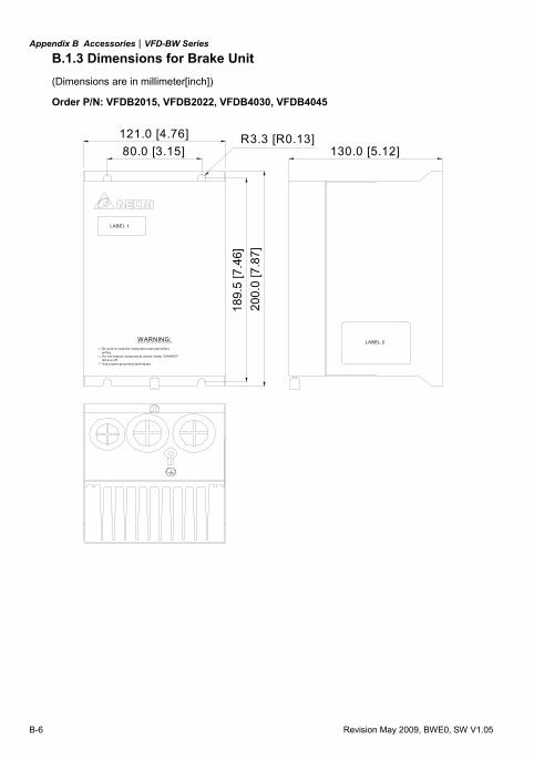
Appendix B Accessories|VFD-BW Series
B-6 Revision May 2009, BWE0, SW V1.05
B.1.3 Dimensions for Brake Unit (Dimensions are in millimeter[inch])
Order P/N: VFDB2015, VFDB2022, VFDB4030, VFDB4045
80.0 [3.15]121.0 [4.76]
189.
5 [7
.46]
200.
0 [7
.87]
130.0 [5.12]R3.3 [R0.13]
lamp is off.Use proper grounding techniques.
Be sure to read the instruction manunal before
Do not inspect components unless inside "CHARGE"wiring.
WARNING:
LABEL 1
LABEL 2
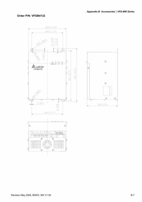
Appendix B Accessories|VFD-BW Series
Revision May 2009, BWE0, SW V1.05 B-7
Order P/N: VFDB4132
VFDB4132
CHARGE ACT OC OH
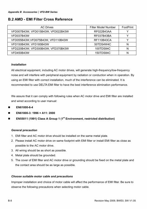
Appendix B Accessories|VFD-BW Series
B-8 Revision May 2009, BWE0, SW V1.05
B.2 AMD - EMI Filter Cross Reference
AC Drives Filter Model Number FootPrintVFD007B43W, VFD015B43W, VFD022B43W RF022B43AA Y VFD037B43W RF037B43BA Y VFD055B43W,VFD075B43W, VFD110B43W RF110B43CA Y VFD150B43W, VFD185B43W 50TDS4W4C N VFD220B43W, VFD300B43W, VFD370B43W 100TDS84C N VFD450B43W 150TDS84C N
Installation
All electrical equipment, including AC motor drives, will generate high-frequency/low-frequency
noise and will interfere with peripheral equipment by radiation or conduction when in operation. By
using an EMI filter with correct installation, much of the interference can be eliminated. It is
recommended to use DELTA EMI filter to have the best interference elimination performance.
We assure that it can comply with following rules when AC motor drive and EMI filter are installed
and wired according to user manual:
EN61000-6-4
EN61800-3: 1996 + A11: 2000
EN55011 (1991) Class A Group 1 (1st Environment, restricted distribution)
General precaution
1. EMI filter and AC motor drive should be installed on the same metal plate.
2. Please install AC motor drive on same footprint with EMI filter or install EMI filter as close as
possible to the AC motor drive.
3. All wiring should be as short as possible.
4. Metal plate should be grounded.
5. The cover of EMI filter and AC motor drive or grounding should be fixed on the metal plate and
the contact area should be as large as possible.
Choose suitable motor cable and precautions Improper installation and choice of motor cable will affect the performance of EMI filter. Be sure to
observe the following precautions when selecting motor cable.
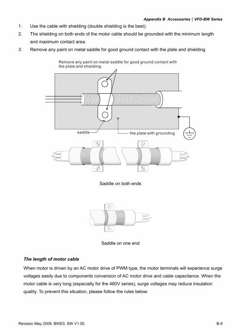
Appendix B Accessories|VFD-BW Series
Revision May 2009, BWE0, SW V1.05 B-9
1. Use the cable with shielding (double shielding is the best).
2. The shielding on both ends of the motor cable should be grounded with the minimum length
and maximum contact area.
3. Remove any paint on metal saddle for good ground contact with the plate and shielding.
Remove any paint on metal saddle for good ground contact with the plate and shielding.
saddle the plate with grounding
Saddle on both ends
Saddle on one end
The length of motor cable When motor is driven by an AC motor drive of PWM type, the motor terminals will experience surge
voltages easily due to components conversion of AC motor drive and cable capacitance. When the
motor cable is very long (especially for the 460V series), surge voltages may reduce insulation
quality. To prevent this situation, please follow the rules below:
Appendix B Accessories|VFD-BW Series
B-10 Revision May 2009, BWE0, SW V1.05
Use a motor with enhanced insulation.
Connect an output reactor (optional) to the output terminals of the AC motor drive
The length of the cable between AC motor drive and motor should be as short as possible
(10 to 20 m or less)
For models 7.5hp/5.5kW and above: Insulation level of motor 1000V 1300V 1600V 460VAC input voltage 66 ft (20m) 328 ft (100m) 1312 ft (400m)
For models 5hp/3.7kW and less: Insulation level of motor 1000V 1300V 1600V 460VAC input voltage 66 ft (20m) 165 ft (50m) 165 ft (50m)
NOTE When a thermal O/L relay protected by motor is used between AC motor drive and motor, it may
malfunction (especially for 460V series), even if the length of motor cable is only 165 ft (50m) or
less. To prevent it, please use AC reactor and/or lower the carrier frequency (Pr. 02-03 PWM
carrier frequency).
Never connect phase lead capacitors or surge absorbers to the output terminals of the AC motor
drive.
If the length is too long, the stray capacitance between cables will increase and may cause
leakage current. It will activate the protection of over current, increase leakage current or not
insure the correction of current display. The worst case is that AC motor drive may be damaged.
If more than one motor is connected to the AC motor drive, the total wiring length is the sum of
the wiring length from AC motor drive to each motor.
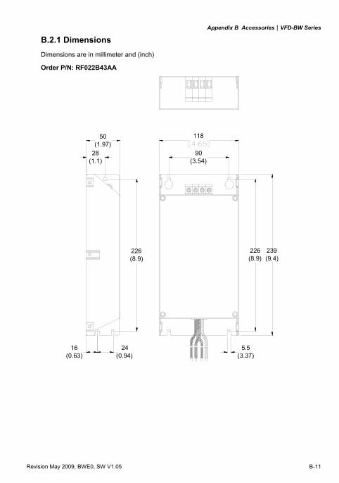
Appendix B Accessories|VFD-BW Series
Revision May 2009, BWE0, SW V1.05 B-11
B.2.1 Dimensions Dimensions are in millimeter and (inch)
Order P/N: RF022B43AA
239(9.4)
118
90(3.54)
28(1.1)
50(1.97)
226(8.9)
5.5(3.37)
226(8.9)
16(0.63)
24(0.94)
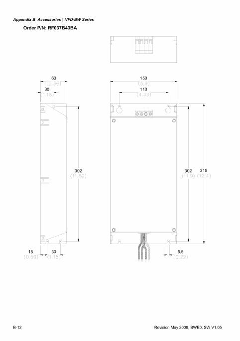
Appendix B Accessories|VFD-BW Series
B-12 Revision May 2009, BWE0, SW V1.05
Order P/N: RF037B43BA
302
110
150
315
5.5
30
60
302
15 30
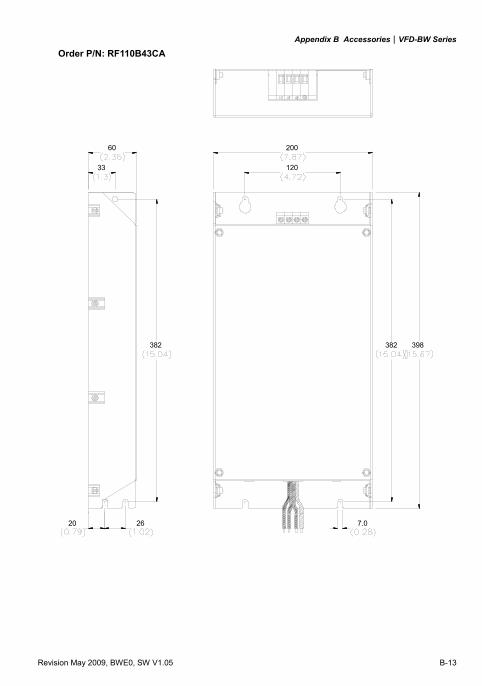
Appendix B Accessories|VFD-BW Series
Revision May 2009, BWE0, SW V1.05 B-13
Order P/N: RF110B43CA
60
33
200
120
398382
2620
382
7.0
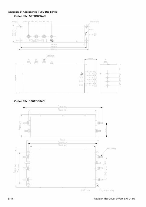
Appendix B Accessories|VFD-BW Series
B-14 Revision May 2009, BWE0, SW V1.05
Order P/N: 50TDS4W4C
Order P/N: 100TDS84C
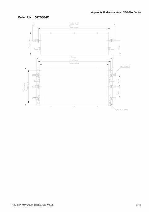
Appendix B Accessories|VFD-BW Series
Revision May 2009, BWE0, SW V1.05 B-15
Order P/N: 150TDS84C
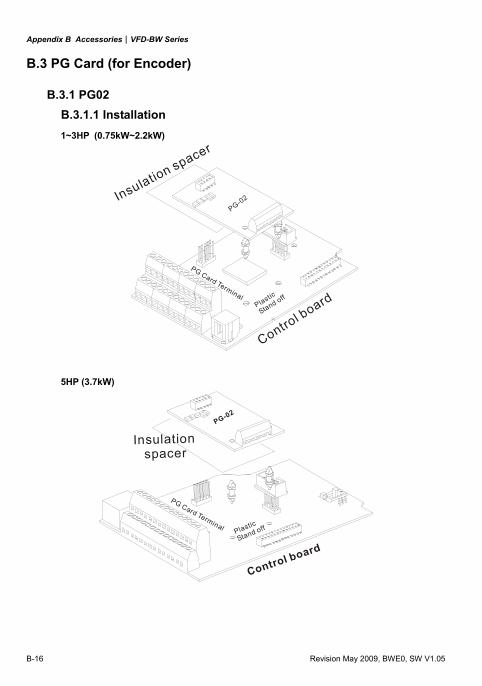
Appendix B Accessories|VFD-BW Series
B-16 Revision May 2009, BWE0, SW V1.05
B.3 PG Card (for Encoder)
B.3.1 PG02 B.3.1.1 Installation 1~3HP (0.75kW~2.2kW)
PG-02
Control boardPlastic
Stand off
PG Card Terminal
Insulation spacer
5HP (3.7kW)
PG-02
Control board
PG Card Terminal
Insulation spacer
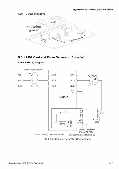
Appendix B Accessories|VFD-BW Series
Revision May 2009, BWE0, SW V1.05 B-17
7.5HP (5.5kW) and above
PG-02
Plastic Stand off
PG Card Terminal
Insulation spacer
B.3.1.2 PG Card and Pulse Generator (Encoder) 1. Basic Wiring Diagram
R/L1
S/L2
T/L3
NFBU/T1
V/T2
W/T3
IM3~
Motor
PGA
B
DCM
PG-02
VP +12VGND
A
B
OC
5VTP
12VFactory Setting
PG-02 and Pulse Generator Connections
Pulse Generator Output 12V DC
A
BA
B
R/L1
S/L2
T/L3
None fused breaker
Main circuit (power) terminals Control circuit terminals
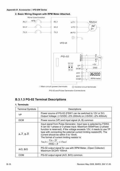
Appendix B Accessories|VFD-BW Series
B-18 Revision May 2009, BWE0, SW V1.05
2. Basic Wiring Diagram with RPM Meter Attached.
R/L1
S/L2
T/L3
NFBU/T1
V/T2
W/T3
IM3~
VP
COM
VFD-B
+5V
GND
OC
5VTP
12V
PG-02 and Pulse Generator Connections
A/O
B/ORPM meter
DCM
PGA
B
A
B
A
BA
B
R/L1
S/L2
T/L3
None fused breaker
Main circuit (power) terminals Control circuit terminals
B.3.1.3 PG-02 Terminal Descriptions
1. Terminals
Terminal Symbols Descriptions
VP Power source of PG-02 (FSW1 can be switched to 12V or 5V) Output Voltage: (+12VDC ±5% 200mA) or (+5VDC ±2% 400mA)
DCM Power source (VP) and input signal (A, B) common
A- A , B-B
Input signal from Pulse Generator. Input type is selected by FSW2. It can be 1-phase or 2-phase input. Maximum 500kP/sec (z-phase function is reserved). If the voltage exceeds 12V, it needs to use TP type with connecting the external current limiting resistor(R). The current should be within 5 to 15mA. The formal of current limiting resistor is:
mAR
VVinmA 15480
25 ≤+Ω
−≤
A/O, B/O PG-02 output signal for use with RPM Meter. (Open Collector) Maximum DC24V 100mA
COM PG-02 output signal (A/O, B/O) common.
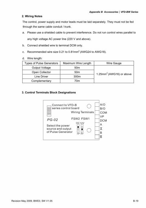
Appendix B Accessories|VFD-BW Series
Revision May 2009, BWE0, SW V1.05 B-19
2. Wiring Notes
The control, power supply and motor leads must be laid separately. They must not be fed
through the same cable conduit / trunk.
a. Please use a shielded cable to prevent interference. Do not run control wires parallel to
any high voltage AC power line (220 V and above).
b. Connect shielded wire to terminal DCM only.
c. Recommended wire size 0.21 to 0.81mm2 (AWG24 to AWG18).
d. Wire length:
Types of Pulse Generators Maximum Wire Length Wire Gauge Output Voltage 50m Open Collector 50m
Line Driver 300m Complementary 70m
1.25mm2 (AWG16) or above
3. Control Terminals Block Designations
OC
5VTP
12V
A/OB/OCOMVPDCMA
B
PG-02 FSW2 FSW1
Connect to VFD-Bseries control board
Wiring Terminals
Select the powersource and outputof Pulse Generator
A
B
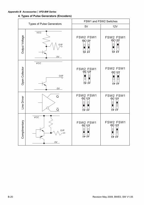
Appendix B Accessories|VFD-BW Series
B-20 Revision May 2009, BWE0, SW V1.05
4. Types of Pulse Generators (Encoders)
FSW1 and FSW2 Switches Types of Pulse Generators
5V 12V O
utpu
t Vol
tage
O/P
0V
VCC
OC
5VTP
12VFSW2 FSW1
FSW2 FSW1OC
5VTP
12V
Ope
n C
olle
ctor
O/P
0V
VCC
FSW2 FSW1OC
5VTP
12V
FSW2 FSW1OC
5VTP
12V
Line
Driv
er Q
Q
FSW2 FSW1OC
5VTP
12V
FSW2 FSW1OC
5VTP
12V
Com
plim
enta
ry
O/P
0V
VCC
FSW2 FSW1OC
5VTP
12V
FSW2 FSW1OC
5VTP
12V
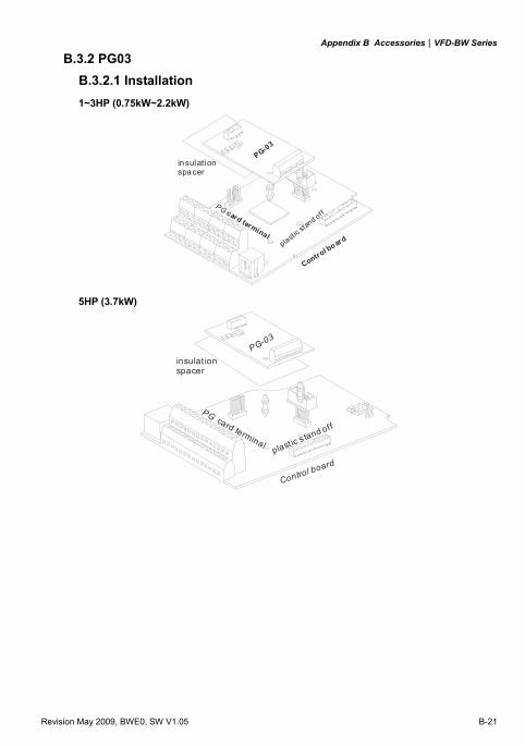
Appendix B Accessories|VFD-BW Series
Revision May 2009, BWE0, SW V1.05 B-21
B.3.2 PG03 B.3.2.1 Installation 1~3HP (0.75kW~2.2kW)
PG-03
Control board
PG card terminalplast i
c stan
d off
insulationspacer
5HP (3.7kW)
PG-03
Control boardplast ic s tand off
PG card terminal
insulat ionspacer
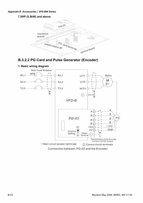
Appendix B Accessories|VFD-BW Series
B-22 Revision May 2009, BWE0, SW V1.05
7.5HP (5.5kW) and above
PG-03
control board
plast ic s tand off
PG card termi nal
insulat ionspacer
B.3.2.2 PG Card and Pulse Generator (Encoder) 1. Basic wiring diagram
NFBR/L1
S/L2
T/L3
U/T1
V/T2
W/T3
M3~
Motor
PG
A
B
12V0V
PG-03
+12VGND
OC
TP
Connection between PG-03 and the Encoder
*Specification of the Encoder is of the 12V/OC Output
A
B
A
B
A
B
ShieldTerminal
R/L1
S/L2
T/L3
Main circuit (power) terminals Control circuit terminals
VFD-B
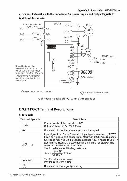
Appendix B Accessories|VFD-BW Series
Revision May 2009, BWE0, SW V1.05 B-23
2. Connect Externally with the Encoder of 5V Power Supply and Output Signals to Additional Tachometer
NFBM3~
VFD-B
OC
TP
A
B12V
0V
A
B
A/OB/O
RPM Meter
0V
A
B
A
B
PG-03
R/L1
S/L2
T/L3
R/L1
S/L2
T/L3
U/T1
V/T2
W/T3
PG
GND5V 5V
0V
Non-Fuse Breaker
*Specification of the Encoder is of 5V/OC output, which could also connect externally with the RPM wire.*Power of the should be supplied by the customers.
RPM meter
Connection between PG-03 and the Encoder
Main circuit (power) terminals Control circuit terminals
DC Power
Shield Terminal
B.3.2.3 PG-03 Terminal Descriptions 1. Terminals
Terminal Symbols Descriptions
+12V Power Supply of the Encoder: +12V Output Voltage: +12V±5% 200mA
0V Common point for the power supply and the signal
A- A , B-B
Input signal from Pulse Generator. Input type is selected by FSW2. It can be 1-phase or 2-phase input. Maximum 500kP/sec (z-phase function is reserved). If the voltage exceeds 12V, it needs to use TP type with connecting the external current limiting resistor(R). The current should be within 5 to 15mA. The formal of current limiting resistor is:
mAR
VVinmA 15600
25 ≤+Ω
−≤
A/O, B/O The Encoder signal output Maximum: DC24V 300mA
Common point for signal grounding
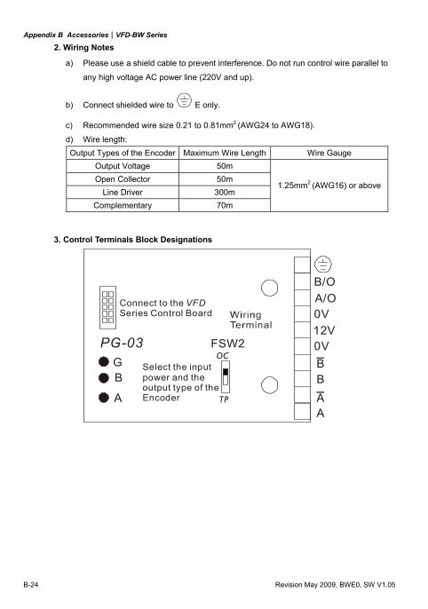
Appendix B Accessories|VFD-BW Series
B-24 Revision May 2009, BWE0, SW V1.05
2. Wiring Notes
a) Please use a shield cable to prevent interference. Do not run control wire parallel to
any high voltage AC power line (220V and up).
b) Connect shielded wire to E only.
c) Recommended wire size 0.21 to 0.81mm2 (AWG24 to AWG18). d) Wire length: Output Types of the Encoder Maximum Wire Length Wire Gauge
Output Voltage 50m Open Collector 50m
Line Driver 300m Complementary 70m
1.25mm2 (AWG16) or above
3. Control Terminals Block Designations
OC
TP
A/OB/O
0V12V0V
AAB
Connect to theSeries Control Board
VFD
Select the input power and the output type of theEncoder
PG-03 FSW2
BGB
A
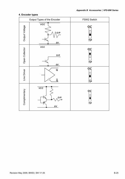
Appendix B Accessories|VFD-BW Series
Revision May 2009, BWE0, SW V1.05 B-25
4. Encoder types
Output Types of the Encoder FSW2 Switch
Out
put V
olta
ge
O/P
0V
VCC
OC
TP
Ope
n C
olle
ctor
O/P
0V
VCC
OC
TP
Line
Driv
er
Q
Q
OC
TP
Com
plim
enta
ry
O/P
0V
VCC
OC
TP
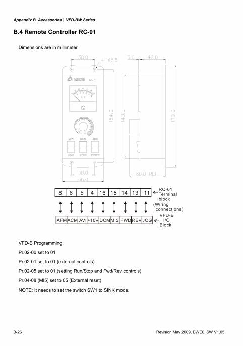
Appendix B Accessories|VFD-BW Series
B-26 Revision May 2009, BWE0, SW V1.05
B.4 Remote Controller RC-01
Dimensions are in millimeter
AFM ACM +10VAVI DCMMI5 FWD REV JOG
8 6 5 4 16 15 14 13 11RC-01Terminalblock
(Wiring connections)
VFD-B I/OBlock
VFD-B Programming:
Pr.02-00 set to 01
Pr.02-01 set to 01 (external controls)
Pr.02-05 set to 01 (setting Run/Stop and Fwd/Rev controls)
Pr.04-08 (MI5) set to 05 (External reset)
NOTE: It needs to set the switch SW1 to SINK mode.
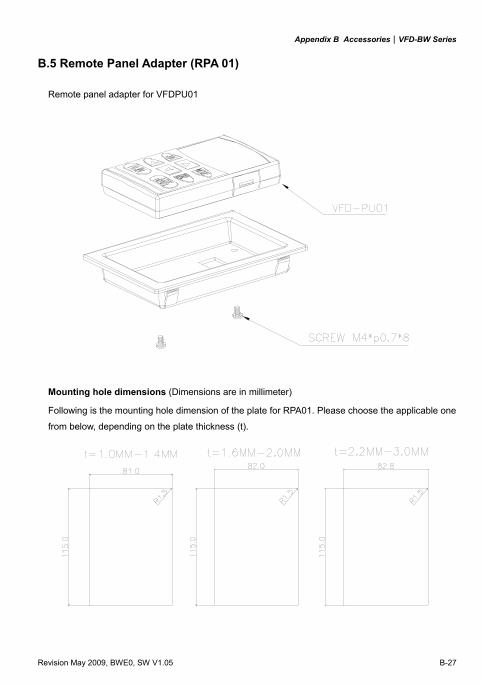
Appendix B Accessories|VFD-BW Series
Revision May 2009, BWE0, SW V1.05 B-27
B.5 Remote Panel Adapter (RPA 01)
Remote panel adapter for VFDPU01
Mounting hole dimensions (Dimensions are in millimeter)
Following is the mounting hole dimension of the plate for RPA01. Please choose the applicable one
from below, depending on the plate thickness (t).
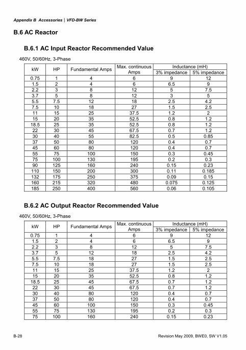
Appendix B Accessories|VFD-BW Series
B-28 Revision May 2009, BWE0, SW V1.05
B.6 AC Reactor
B.6.1 AC Input Reactor Recommended Value 460V, 50/60Hz, 3-Phase
Inductance (mH) kW HP Fundamental Amps Max. continuous Amps 3% impedance 5% impedance
0.75 1 4 6 9 12 1.5 2 4 6 6.5 9 2.2 3 8 12 5 7.5 3.7 5 8 12 3 5 5.5 7.5 12 18 2.5 4.2 7.5 10 18 27 1.5 2.5 11 15 25 37.5 1.2 2 15 20 35 52.5 0.8 1.2
18.5 25 35 52.5 0.8 1.2 22 30 45 67.5 0.7 1.2 30 40 55 82.5 0.5 0.85 37 50 80 120 0.4 0.7 45 60 80 120 0.4 0.7 55 75 100 150 0.3 0.45 75 100 130 195 0.2 0.3 90 125 160 240 0.15 0.23
110 150 200 300 0.11 0.185 132 175 250 375 0.09 0.15 160 215 320 480 0.075 0.125 185 250 400 560 0.06 0.105
B.6.2 AC Output Reactor Recommended Value 460V, 50/60Hz, 3-Phase
Inductance (mH) kW HP Fundamental Amps Max. continuous Amps 3% impedance 5% impedance
0.75 1 4 6 9 12 1.5 2 4 6 6.5 9 2.2 3 8 12 5 7.5 3.7 5 12 18 2.5 4.2 5.5 7.5 18 27 1.5 2.5 7.5 10 18 27 1.5 2.5 11 15 25 37.5 1.2 2 15 20 35 52.5 0.8 1.2
18.5 25 45 67.5 0.7 1.2 22 30 45 67.5 0.7 1.2 30 40 80 120 0.4 0.7 37 50 80 120 0.4 0.7 45 60 100 150 0.3 0.45 55 75 130 195 0.2 0.3 75 100 160 240 0.15 0.23
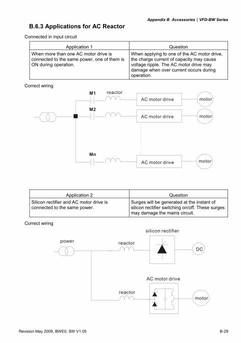
Appendix B Accessories|VFD-BW Series
Revision May 2009, BWE0, SW V1.05 B-29
B.6.3 Applications for AC Reactor Connected in input circuit
Application 1 Question When more than one AC motor drive is connected to the same power, one of them is ON during operation.
When applying to one of the AC motor drive, the charge current of capacity may cause voltage ripple. The AC motor drive may damage when over current occurs during operation.
Correct wiring M1
M2
Mn
reactorAC motor drive
AC motor drive
AC motor drive
motor
motor
motor
Application 2 Question Silicon rectifier and AC motor drive is connected to the same power.
Surges will be generated at the instant of silicon rectifier switching on/off. These surges may damage the mains circuit.
Correct wiring
DC
power reactor
reactor
AC motor drive
motor
silicon rectifier
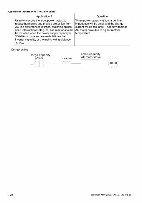
Appendix B Accessories|VFD-BW Series
B-30 Revision May 2009, BWE0, SW V1.05
Application 3 Question Used to improve the input power factor, to reduce harmonics and provide protection from AC line disturbances (surges, switching spikes, short interruptions, etc.). AC line reactor should be installed when the power supply capacity is 500kVA or more and exceeds 6 times the inverter capacity, or the mains wiring distance ≤ 10m.
When power capacity is too large, line impedance will be small and the charge current will be too large. That may damage AC motor drive due to higher rectifier temperature.
Correct wiring
large-capacity power reactor
small-capacityAC motor drive
motor
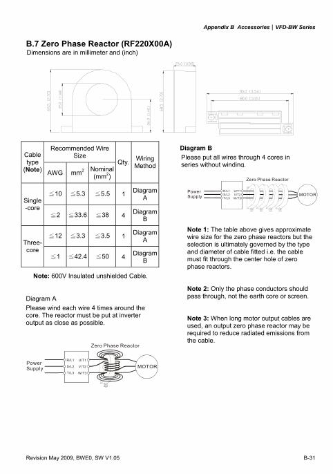
Appendix B Accessories|VFD-BW Series
Revision May 2009, BWE0, SW V1.05 B-31
B.7 Zero Phase Reactor (RF220X00A)
Recommended Wire
Size Cable type
(Note) AWG mm2 Nominal(mm2)
Qty. Wiring Method
≦10 ≦5.3 ≦5.5 1 Diagram A Single
-core ≦2 ≦33.6 ≦38 4 Diagram
B
≦12 ≦3.3 ≦3.5 1 Diagram A Three-
core ≦1 ≦42.4 ≦50 4 Diagram
B
Note: 600V Insulated unshielded Cable.
PowerSupply
Zero Phase Reactor
MOTORU/T1
V/T2
W/T3
R/L1
S/L2
T/L3
U/T1V/T2W/T3
R/L1S/L2T/L3
PowerSupply
Zero Phase Reactor
MOTOR
Note 1: The table above gives approximate wire size for the zero phase reactors but the selection is ultimately governed by the type and diameter of cable fitted i.e. the cable must fit through the center hole of zero phase reactors. Note 2: Only the phase conductors should pass through, not the earth core or screen. Note 3: When long motor output cables are used, an output zero phase reactor may be required to reduce radiated emissions from the cable.
Dimensions are in millimeter and (inch)
Diagram B Please put all wires through 4 cores in series without winding.
Diagram A Please wind each wire 4 times around the core. The reactor must be put at inverter output as close as possible.
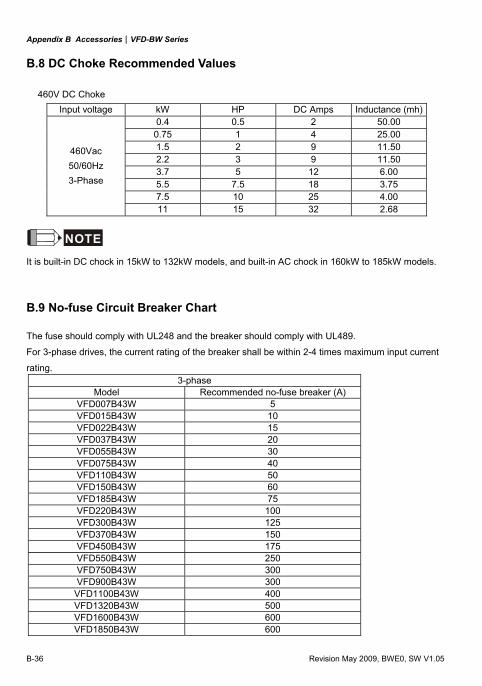
Appendix B Accessories|VFD-BW Series
B-36 Revision May 2009, BWE0, SW V1.05
B.8 DC Choke Recommended Values
460V DC Choke Input voltage kW HP DC Amps Inductance (mh)
0.4 0.5 2 50.00 0.75 1 4 25.00 1.5 2 9 11.50 2.2 3 9 11.50 3.7 5 12 6.00 5.5 7.5 18 3.75 7.5 10 25 4.00
460Vac 50/60Hz 3-Phase
11 15 32 2.68
NOTE
It is built-in DC chock in 15kW to 132kW models, and built-in AC chock in 160kW to 185kW models.
B.9 No-fuse Circuit Breaker Chart
The fuse should comply with UL248 and the breaker should comply with UL489.
For 3-phase drives, the current rating of the breaker shall be within 2-4 times maximum input current
rating. 3-phase
Model Recommended no-fuse breaker (A) VFD007B43W 5 VFD015B43W 10 VFD022B43W 15 VFD037B43W 20 VFD055B43W 30 VFD075B43W 40 VFD110B43W 50 VFD150B43W 60 VFD185B43W 75 VFD220B43W 100 VFD300B43W 125 VFD370B43W 150 VFD450B43W 175 VFD550B43W 250 VFD750B43W 300 VFD900B43W 300
VFD1100B43W 400 VFD1320B43W 500 VFD1600B43W 600 VFD1850B43W 600
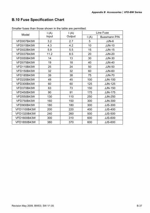
Appendix B Accessories|VFD-BW Series
Revision May 2009, BWE0, SW V1.05 B-37
B.10 Fuse Specification Chart
Smaller fuses than those shown in the table are permitted. Line Fuse
Model I (A) Input
I (A) Output I (A) Bussmann P/N
VFD007B43W 3.2 2.7 5 JJN-6 VFD015B43W 4.3 4.2 10 JJN-10 VFD022B43W 5.9 5.5 15 JJN-15 VFD037B43W 11.2 8.5 20 JJN-20 VFD055B43W 14 13 30 JJN-30 VFD075B43W 19 18 40 JJN-40 VFD110B43W 25 24 50 JJN-50 VFD150B43W 32 32 60 JJN-60 VFD185B43W 39 38 75 JJN-70 VFD220B43W 49 45 100 JJN-100 VFD300B43W 60 60 125 JJN-125 VFD370B43W 63 73 150 JJN-150 VFD450B43W 90 91 175 JJN-175 VFD550B43W 130 110 250 JJN-250 VFD750B43W 160 150 300 JJN-300 VFD900B43W 180 180 300 JJS-300 VFD1100B43W 200 220 400 JJS-400 VFD1320B43W 240 260 500 JJS-500 VFD1600B43W 300 310 600 JJS-600 VFD1850B43W 380 370 600 JJS-600
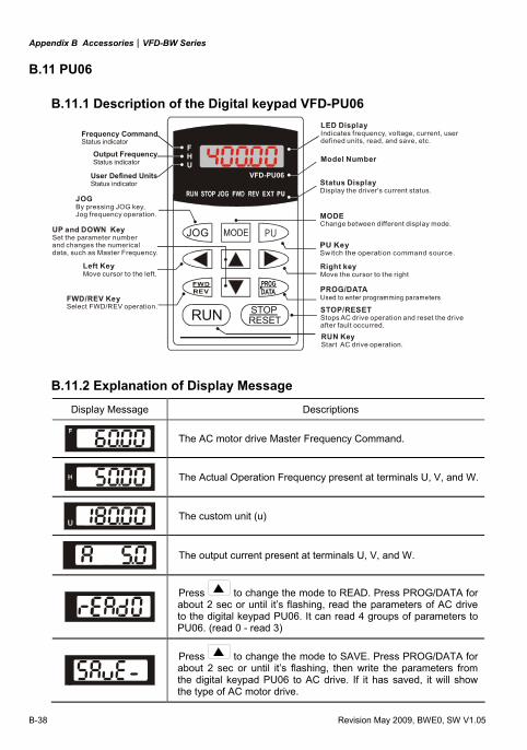
Appendix B Accessories|VFD-BW Series
B-38 Revision May 2009, BWE0, SW V1.05
B.11 PU06
B.11.1 Description of the Digital keypad VFD-PU06
U
FH
VFD-PU06
JOG
RUN RESETSTOP
LED DisplayIndicates frequency, voltage, current, userdefined units, read, and save, etc.
Status DisplayDisplay the driver's current status.
Model Number
STOP/RESET
Stops AC drive operation and reset the drive after fault occurred.
PU
EXT PU
Right keyMove the cursor to the right
RUN KeyStart AC drive operation.
Frequency CommandStatus indicator
Output FrequencyStatus indicator
User Defined UnitsStatus indicator
JOGBy pressing JOG key,Jog frequency operation. MODE
Change between different display mode.
Left KeyMove cursor to the left.
UP and DOWN KeySet the parameter number and changes the numerical data, such as Master Frequency.
FWD/REV KeySelect FWD/REV operation.
B.11.2 Explanation of Display Message
Display Message Descriptions
The AC motor drive Master Frequency Command.
The Actual Operation Frequency present at terminals U, V, and W.
The custom unit (u)
The output current present at terminals U, V, and W.
Press to change the mode to READ. Press PROG/DATA for about 2 sec or until it’s flashing, read the parameters of AC drive to the digital keypad PU06. It can read 4 groups of parameters to PU06. (read 0 - read 3)
Press to change the mode to SAVE. Press PROG/DATA for about 2 sec or until it’s flashing, then write the parameters from the digital keypad PU06 to AC drive. If it has saved, it will show the type of AC motor drive.
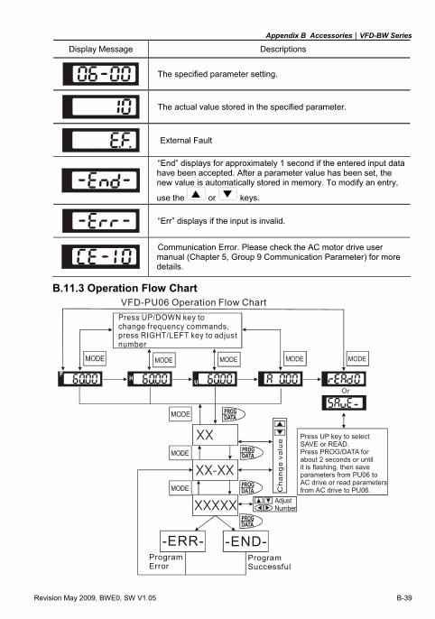
Appendix B Accessories|VFD-BW Series
Revision May 2009, BWE0, SW V1.05 B-39
Display Message Descriptions
The specified parameter setting.
The actual value stored in the specified parameter.
External Fault
“End” displays for approximately 1 second if the entered input data have been accepted. After a parameter value has been set, the new value is automatically stored in memory. To modify an entry,
use the or keys.
“Err” displays if the input is invalid.
Communication Error. Please check the AC motor drive user manual (Chapter 5, Group 9 Communication Parameter) for more details.
B.11.3 Operation Flow Chart
XX XX-XX
XXXXX
-END-
VFD-PU06 Operation Flow Chart
Program Error
-ERR-
Or
ProgramSuccessful
Press UP key to selectSAVE or READ.Press PROG/DATA for about 2 seconds or until it is flashing, then saveparameters
or read parameters.
from PU06 to AC drive from AC drive to PU06

Appendix B Accessories|VFD-BW Series
B-40 Revision May 2009, BWE0, SW V1.05
This page intentionally left blank.
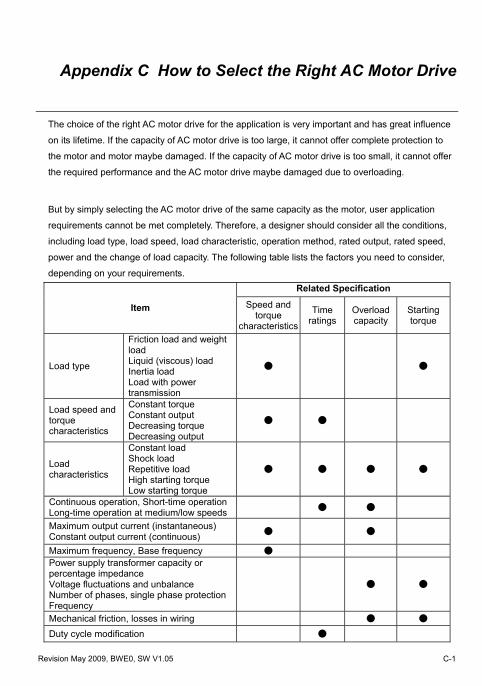
Revision May 2009, BWE0, SW V1.05 C-1
Appendix C How to Select the Right AC Motor Drive
The choice of the right AC motor drive for the application is very important and has great influence
on its lifetime. If the capacity of AC motor drive is too large, it cannot offer complete protection to
the motor and motor maybe damaged. If the capacity of AC motor drive is too small, it cannot offer
the required performance and the AC motor drive maybe damaged due to overloading.
But by simply selecting the AC motor drive of the same capacity as the motor, user application
requirements cannot be met completely. Therefore, a designer should consider all the conditions,
including load type, load speed, load characteristic, operation method, rated output, rated speed,
power and the change of load capacity. The following table lists the factors you need to consider,
depending on your requirements. Related Specification
Item Speed and torque
characteristics
Time ratings
Overload capacity
Starting torque
Load type
Friction load and weight load Liquid (viscous) load Inertia load Load with power transmission
Load speed and torque characteristics
Constant torque Constant output Decreasing torque Decreasing output
Load characteristics
Constant load Shock load Repetitive load High starting torque Low starting torque
Continuous operation, Short-time operationLong-time operation at medium/low speeds
Maximum output current (instantaneous) Constant output current (continuous)
Maximum frequency, Base frequency Power supply transformer capacity or percentage impedance Voltage fluctuations and unbalance Number of phases, single phase protectionFrequency
Mechanical friction, losses in wiring
Duty cycle modification
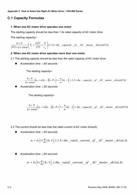
Appendix C How to Select the Right AC Motor Drive|VFD-BW Series
C-2 Revision May 2009, BWE0, SW V1.05
C.1 Capacity Formulas
1. When one AC motor drive operates one motor
The starting capacity should be less than 1.5x rated capacity of AC motor drive
The starting capacity=
)(_____5.1375cos973
2
kVAdrivemotorACofcapacitythetNGDTNk
AL ×≤⎟⎟
⎠
⎞⎜⎜⎝
⎛×+
×××
ϕη
2. When one AC motor drive operates more than one motor
2.1 The starting capacity should be less than the rated capacity of AC motor drive
Acceleration time ≦60 seconds
The starting capacity=
( )[ ] ( ) )(_____5.11cos
111 kVAdrivemotorACofcapacitytheknnPknnNk
sCssT
sT ×≤+=+
××
⎥⎥⎥
⎦
⎤
⎢⎢⎢
⎣
⎡
−−ϕη
Acceleration time ≧60 seconds
The starting capacity=
( )[ ] ( ) )(_____1cos
111 kVAdrivemotorACofcapacitytheknnPknnNk
sCssT
sT ≤+=+
××
⎥⎥⎥
⎦
⎤
⎢⎢⎢
⎣
⎡
−−ϕη
2.2 The current should be less than the rated current of AC motor drive(A)
Acceleration time ≦60 seconds
)(______5.111 AdrivemotorACofcurrentratedtheknnIn SM
T
ST ×≤++ ⎥
⎦
⎤⎢⎣
⎡⎟⎠⎞⎜
⎝⎛ −
Acceleration time ≧60 seconds
)(______11 AdrivemotorACofcurrentratedtheknnIn SM
T
ST ≤++ ⎥
⎦
⎤⎢⎣
⎡⎟⎠⎞⎜
⎝⎛ −
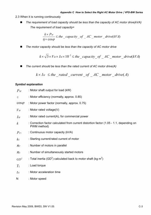
Appendix C How to Select the Right AC Motor Drive|VFD-BW Series
Revision May 2009, BWE0, SW V1.05 C-3
2.3 When it is running continuously
The requirement of load capacity should be less than the capacity of AC motor drive(kVA)
The requirement of load capacity=
)(_____cos
kVAdrivemotorACofcapacitythePk M≤
××
ϕη
The motor capacity should be less than the capacity of AC motor drive
)(_____103 3 kVAdrivemotorACofcapacitytheIVk MM ≤×××× −
The current should be less than the rated current of AC motor drive(A)
)(______ AdrivemotorACofcurrentratedtheIk M ≤×
Symbol explanation
MP : Motor shaft output for load (kW)
η : Motor efficiency (normally, approx. 0.85)
ϕcos : Motor power factor (normally, approx. 0.75)
MV : Motor rated voltage(V)
MI : Motor rated current(A), for commercial power
k : Correction factor calculated from current distortion factor (1.05 - 1.1, depending on PWM method)
1CP : Continuous motor capacity (kVA)
Sk : Starting current/rated current of motor
Tn : Number of motors in parallel
Sn : Number of simultaneously started motors
2GD : Total inertia (GD2) calculated back to motor shaft (kg m2)
LT : Load torque
At : Motor acceleration time
N : Motor speed
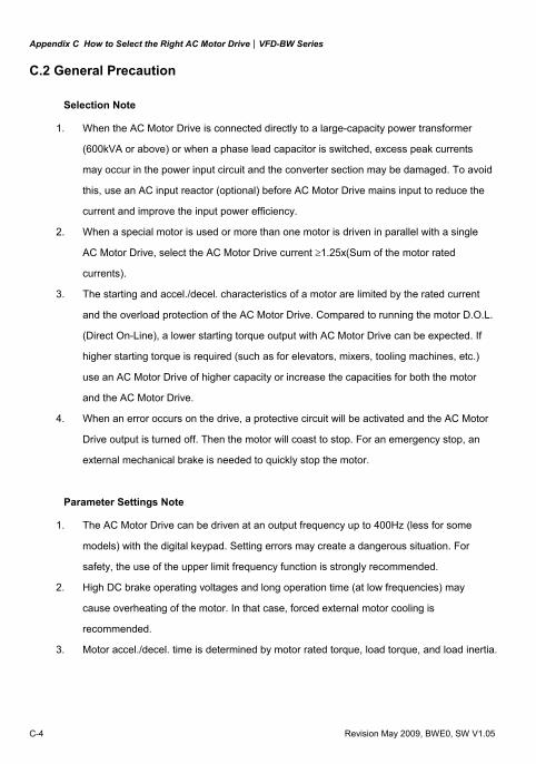
Appendix C How to Select the Right AC Motor Drive|VFD-BW Series
C-4 Revision May 2009, BWE0, SW V1.05
C.2 General Precaution
Selection Note
1. When the AC Motor Drive is connected directly to a large-capacity power transformer
(600kVA or above) or when a phase lead capacitor is switched, excess peak currents
may occur in the power input circuit and the converter section may be damaged. To avoid
this, use an AC input reactor (optional) before AC Motor Drive mains input to reduce the
current and improve the input power efficiency.
2. When a special motor is used or more than one motor is driven in parallel with a single
AC Motor Drive, select the AC Motor Drive current ≥1.25x(Sum of the motor rated
currents).
3. The starting and accel./decel. characteristics of a motor are limited by the rated current
and the overload protection of the AC Motor Drive. Compared to running the motor D.O.L.
(Direct On-Line), a lower starting torque output with AC Motor Drive can be expected. If
higher starting torque is required (such as for elevators, mixers, tooling machines, etc.)
use an AC Motor Drive of higher capacity or increase the capacities for both the motor
and the AC Motor Drive.
4. When an error occurs on the drive, a protective circuit will be activated and the AC Motor
Drive output is turned off. Then the motor will coast to stop. For an emergency stop, an
external mechanical brake is needed to quickly stop the motor.
Parameter Settings Note
1. The AC Motor Drive can be driven at an output frequency up to 400Hz (less for some
models) with the digital keypad. Setting errors may create a dangerous situation. For
safety, the use of the upper limit frequency function is strongly recommended.
2. High DC brake operating voltages and long operation time (at low frequencies) may
cause overheating of the motor. In that case, forced external motor cooling is
recommended.
3. Motor accel./decel. time is determined by motor rated torque, load torque, and load inertia.
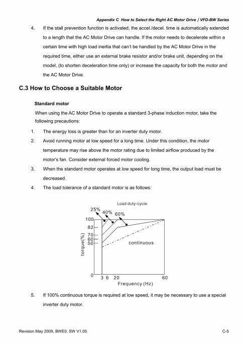
Appendix C How to Select the Right AC Motor Drive|VFD-BW Series
Revision May 2009, BWE0, SW V1.05 C-5
4. If the stall prevention function is activated, the accel./decel. time is automatically extended
to a length that the AC Motor Drive can handle. If the motor needs to decelerate within a
certain time with high load inertia that can’t be handled by the AC Motor Drive in the
required time, either use an external brake resistor and/or brake unit, depending on the
model, (to shorten deceleration time only) or increase the capacity for both the motor and
the AC Motor Drive.
C.3 How to Choose a Suitable Motor
Standard motor
When using the AC Motor Drive to operate a standard 3-phase induction motor, take the
following precautions:
1. The energy loss is greater than for an inverter duty motor.
2. Avoid running motor at low speed for a long time. Under this condition, the motor
temperature may rise above the motor rating due to limited airflow produced by the
motor’s fan. Consider external forced motor cooling.
3. When the standard motor operates at low speed for long time, the output load must be
decreased.
4. The load tolerance of a standard motor is as follows:
3 6 20 60
100
82
70
60
50
0
60%
40%
25%
to
rque
(%)
continuous
Frequency (Hz)
Load duty-cycle
5. If 100% continuous torque is required at low speed, it may be necessary to use a special
inverter duty motor.
Appendix C How to Select the Right AC Motor Drive|VFD-BW Series
C-6 Revision May 2009, BWE0, SW V1.05
6. Motor dynamic balance and rotor endurance should be considered once the operating
speed exceeds the rated speed (60Hz) of a standard motor.
7. Motor torque characteristics vary when an AC Motor Drive instead of commercial power
supply drives the motor. Check the load torque characteristics of the machine to be
connected.
8. Because of the high carrier frequency PWM control of the VFD series, pay attention to the
following motor vibration problems: Resonant mechanical vibration: anti-vibration (damping) rubbers should be
used to mount equipment that runs at varying speed.
Motor imbalance: special care is required for operation at 50 or 60 Hz and
higher frequency.
To avoid resonances, use the Skip frequencies.
9. The motor fan will be very noisy when the motor speed exceeds 50 or 60Hz.
Special motors:
1. Pole-changing (Dahlander) motor:
The rated current is differs from that of a standard motor. Please check before operation
and select the capacity of the AC motor drive carefully. When changing the pole number
the motor needs to be stopped first. If over current occurs during operation or
regenerative voltage is too high, please let the motor free run to stop (coast).
2. Submersible motor:
The rated current is higher than that of a standard motor. Please check before operation
and choose the capacity of the AC motor drive carefully. With long motor cable between
AC motor drive and motor, available motor torque is reduced.
3. Explosion-proof (Ex) motor:
Needs to be installed in a safe place and the wiring should comply with the (Ex)
requirements. Delta AC Motor Drives are not suitable for (Ex) areas with special
precautions.
4. Gear reduction motor:
The lubricating method of reduction gearbox and speed range for continuous operation
will be different and depending on brand. The lubricating function for operating long time
at low speed and for high-speed operation needs to be considered carefully.
Appendix C How to Select the Right AC Motor Drive|VFD-BW Series
Revision May 2009, BWE0, SW V1.05 C-7
5. Synchronous motor:
The rated current and starting current are higher than for standard motors. Please check
before operation and choose the capacity of the AC motor drive carefully. When the AC
motor drive operates more than one motor, please pay attention to starting and changing
the motor.
Power Transmission Mechanism
Pay attention to reduced lubrication when operating gear reduction motors, gearboxes, belts
and chains, etc. over longer periods at low speeds. At high speeds of 50/60Hz and above,
lifetime reducing noises and vibrations may occur.
Motor torque
The torque characteristics of a motor operated by an AC motor drive and commercial mains
power are different. Below you’ll find the torque-speed characteristics of a standard motor (4-pole, 15kW):
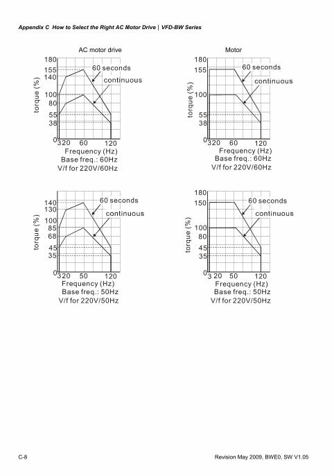
Appendix C How to Select the Right AC Motor Drive|VFD-BW Series
C-8 Revision May 2009, BWE0, SW V1.05
AC motor drive Motor 180155140
10080
5538
0320 60 120
60 seconds
Base freq.: 60HzV/f for 220V/60Hz
180155
100
5538
0320 60 120
torq
ue (%
)
Frequency (Hz) Frequency (Hz)
60 seconds60 seconds
torq
ue (%
)
Base freq.: 60HzV/f for 220V/60Hz
130140
10085
4535
0320 50 120
180150
100
4535
0 50 120
68 80
torq
ue (%
)
torq
ue (%
)
60 seconds 60 seconds
Frequency (Hz)Frequency (Hz)3 20
Base freq.: 50HzV/f for 220V/50Hz
Base freq.: 50HzV/f for 220V/50Hz