Embed Size (px)
Citation preview

This is an unvented gas-fired heater. It uses air (oxygen) from the room in which it is installed. Provisions for adequate combustion and venti-lation air must be provided. Refer to Page 8.
INSTALLER: Leave this manual with the appliance.CONSUMER: Retain this manual for future
reference.
• Do not store or use gasoline or other flammable vapors and liquids in the vicinity of this or any other appliance.
• WHAT TO DO IF YOU SMELL GAS – Do not try to light any appliance. – Do not touch any electrical switch; do
not use any phone in your building. – Leave the building immediately. – Immediately call your gas supplier from
a neighbor's phone. Follow the gas supplier's instructions.
– If you cannot reach your gas supplier, call the fire department.
• Installation and service must be performed by a qualified installer, service agency or the gas supplier.
WARNING: If the information in this manual is not followed exactly, a fire or explosion may result causing property damage, personal injury or loss of life.
VFC Vent Free Fireplace System Installation & Operating InstructionsModels: VFC24C, VFC24L, VFC32C & VFC32L
Monessen • VFC 24/32 Owner Manual • 20308011 • Rev B • 04/18
2
VFC Vent Free Fireplace System
Monessen • VFC 24/32 Owner Manual • 20308011 • Rev B • 04/18
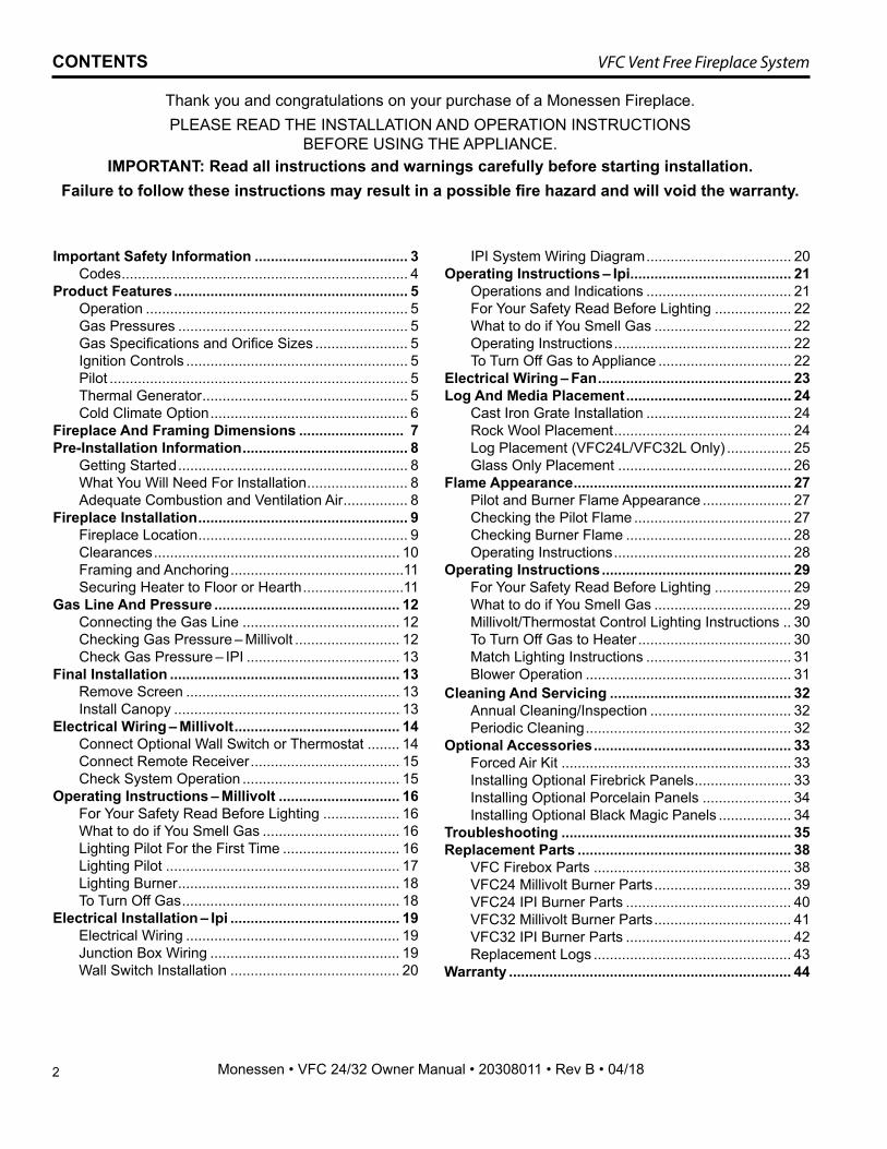
CONTENTS
Thank you and congratulations on your purchase of a Monessen Fireplace.PLEASE READ THE INSTALLATION AND OPERATION INSTRUCTIONS
BEFORE USING THE APPLIANCE.IMPORTANT: Read all instructions and warnings carefully before starting installation.
Failure to follow these instructions may result in a possible fire hazard and will void the warranty.
Important Safety Information ...................................... 3Codes ....................................................................... 4
Product Features .......................................................... 5Operation ................................................................. 5Gas Pressures ......................................................... 5Gas Specifications and Orifice Sizes ....................... 5Ignition Controls ....................................................... 5Pilot .......................................................................... 5Thermal Generator ................................................... 5Cold Climate Option ................................................. 6
Fireplace And Framing Dimensions .......................... 7Pre-Installation Information ......................................... 8
Getting Started ......................................................... 8What You Will Need For Installation ......................... 8Adequate Combustion and Ventilation Air ................ 8
Fireplace Installation .................................................... 9Fireplace Location .................................................... 9Clearances ............................................................. 10Framing and Anchoring ...........................................11Securing Heater to Floor or Hearth .........................11
Gas Line And Pressure .............................................. 12Connecting the Gas Line ....................................... 12Checking Gas Pressure – Millivolt .......................... 12Check Gas Pressure – IPI ...................................... 13
Final Installation ......................................................... 13Remove Screen ..................................................... 13Install Canopy ........................................................ 13
Electrical Wiring – Millivolt ......................................... 14Connect Optional Wall Switch or Thermostat ........ 14Connect Remote Receiver ..................................... 15Check System Operation ....................................... 15
Operating Instructions – Millivolt .............................. 16For Your Safety Read Before Lighting ................... 16What to do if You Smell Gas .................................. 16Lighting Pilot For the First Time ............................. 16Lighting Pilot .......................................................... 17Lighting Burner ....................................................... 18To Turn Off Gas ...................................................... 18
Electrical Installation – Ipi .......................................... 19Electrical Wiring ..................................................... 19Junction Box Wiring ............................................... 19Wall Switch Installation .......................................... 20
IPI System Wiring Diagram .................................... 20Operating Instructions – Ipi ........................................ 21
Operations and Indications .................................... 21For Your Safety Read Before Lighting ................... 22What to do if You Smell Gas .................................. 22Operating Instructions ............................................ 22To Turn Off Gas to Appliance ................................. 22
Electrical Wiring – Fan ................................................ 23Log And Media Placement ......................................... 24
Cast Iron Grate Installation .................................... 24Rock Wool Placement ............................................ 24Log Placement (VFC24L/VFC32L Only) ................ 25Glass Only Placement ........................................... 26
Flame Appearance ...................................................... 27Pilot and Burner Flame Appearance ...................... 27Checking the Pilot Flame ....................................... 27Checking Burner Flame ......................................... 28Operating Instructions ............................................ 28
Operating Instructions ............................................... 29For Your Safety Read Before Lighting ................... 29What to do if You Smell Gas .................................. 29Millivolt/Thermostat Control Lighting Instructions .. 30To Turn Off Gas to Heater ...................................... 30Match Lighting Instructions .................................... 31Blower Operation ................................................... 31
Cleaning And Servicing ............................................. 32Annual Cleaning/Inspection ................................... 32Periodic Cleaning ................................................... 32
Optional Accessories ................................................. 33Forced Air Kit ......................................................... 33Installing Optional Firebrick Panels ........................ 33Installing Optional Porcelain Panels ...................... 34Installing Optional Black Magic Panels .................. 34
Troubleshooting ......................................................... 35Replacement Parts ..................................................... 38
VFC Firebox Parts ................................................. 38VFC24 Millivolt Burner Parts .................................. 39VFC24 IPI Burner Parts ......................................... 40VFC32 Millivolt Burner Parts .................................. 41VFC32 IPI Burner Parts ......................................... 42Replacement Logs ................................................. 43
Warranty ...................................................................... 44
3
VFC Vent Free Fireplace System
Monessen • VFC 24/32 Owner Manual • 20308011 • Rev B • 04/18
IMPORTANT SAFETY INFORMATION
INSTALLERPlease leave these instructions with the appliance.
OWNERPlease retain these instructions for future reference.
WARNING: • Any change to this heater or its controls can be dangerous.
• Improper installation or use of the heater can cause serious injury or death from fire, burns, explosion or carbon monoxide poisoning.
• Do not allow fans to blow directly into the fireplace. Avoid any drafts that alter burner flame patterns.
• Do not use a blower insert, heat exchanger insert or other accessory, not approved for use with this heater where applicable.
13. Avoid any drafts that alter burner flame patterns. Do not allow fans to blow directly into fireplace. Do not place a blower inside burn area of firebox. Ceiling fans may create drafts that alter burner flame patterns. Sooting and improper burning will occur.
14. CAUTION: Candles, incense, oil lamps, etc. produce combustion byproducts including soot. Vent-free appliances will not filter or clean soot produced by these types of products. In addition, the smoke and/or aromatics (scents) may be reburned in the vent-free appliance which can produce odors. It is recommended to minimize the use of candles, incense, etc. while the vent-free appliance is in operation.
15. This is an unvented gas-fired heater. It uses air (oxygen) from the room in which it is installed. Provi-sions for adequate combustion and ventilation air must be provided.
16. This heater shall not be installed in a room or space unless the required volume of indoor combustion air is provided by the method described in the National Fuel Gas Code, ANSI Z223.1/NFPA 54, the International Fuel Gas Code or applicable local codes.
17. Keep room area clear and free from combustible mate-rials, gasoline and other flammable vapors and liquids.
18. Unvented gas heaters are a supplemental zone heater. They are not intended to be the primary heating appli-ance.
19. Unvented gas heaters emit moisture into the living area. In most homes of average construction, this does not pose a problem. In houses of extremely tight construction, additional mechanical ventilation is recommended.
20. During manufacturing, fabricating and shipping, various components of this appliance are treated with certain oils, films or bonding agents. These chemicals are not harmful but may produce annoying smoke and smells as they are burned off during the initial operation of the appliance; possibly causing headaches or eye or lung irritation. This is a normal and temporary occurrence.
1. Due to high temperatures, the appliance should be located out of traffic and away from furniture and draperies.
2. Children and adults should be alerted to the hazard of high surface temperature and should stay away to avoid burns or clothing ignition.
3. Young children should be carefully supervised when they are in the same room with the appliance.
4. Do not place clothing or other flammable material on or near the appliance.
5. Any safety screen or guard removed for servicing an appliance, must be replaced prior to operating the heater.
6. Installation and repair should be done by a qualified service person.
7. To prevent malfunction and/or sooting, an unvented gas heater should be cleaned before use and at least annually by a professional service person. More frequent cleaning may be required due to excessive lint from carpeting, bedding materials, etc. It is imperative that control compartments, burners and circulating air passageways be kept clean.
8. CARBON MONOXIDE POISONING: Early signs of carbon monoxide poisoning are similar to the flu with headaches, dizziness and/or nausea. If you have these signs, obtain fresh air immediately. Have the heater serviced as it may not be operating properly.
9. The installation must conform with local codes or, in the absence of local codes, with the National Fuel Gas Code, ANSI Z223.l/NFPA54.
10. This unit complies with the latest edition of ANSI Z21.11.2–2013, Unvented Heaters.
11. Do not install the heaters in a bathroom or bedroom.12. Correct installation of the refractory cement logs,
proper location of the heater, and annual cleaning are necessary to avoid potential problems with sooting. Sooting, resulting from improper installation or opera-tion, can settle on surfaces outside the fireplace. See log placement instructions for proper installation.
4
VFC Vent Free Fireplace System
Monessen • VFC 24/32 Owner Manual • 20308011 • Rev B • 04/18
IMPORTANT SAFETY INFORMATION
CODESAdhere to all local codes or, in their absence, the latest edition of THE NATIONAL FUEL GAS CODE ANSI Z223.1 or NFPA54 which can be obtained from:
American National Standards Institute, Inc.1430 Broadway
New York, NY 10018or
National Fire Protection Association, Inc.Batterymarch ParkQuincy, MA 02269
The initial break-in operation should last six hours with the burner at the highest setting. Provide maximum ventilation by opening windows or doors to allow odors to dissipate. Any odors remaining after this initial break-in period will be slight and will disappear with continued use.
21. Input ratings are shown in BTU per hour and are for elevations up to 2,000 feet. For elevations above 2,000 feet, input ratings should be reduced 4 percent for each 1,000 feet above sea level. Refer to the National Fuel Gas Code.
22. The appliance must be isolated from the gas supply piping system by closing its equipment shutoff valve during any pressure testing of the gas supply piping system at test pressures equal to or less than 1/2 psig (3.5 kPa).
23. Do not use this room heater if any part has been under water. Immediately call a qualified service technician to inspect the room heater and to replace any part of the control system and any gas control which has been under water.
24. Never burn solid fuels in a fireplace where a unvented room heater is installed.
25. Always have a fireplace screen in place when the appliance is in operation and, unless other provisions for combustion air are provided, the screen must have an opening(s) for induction of combustion air.
THIS APPLIANCE MAY BE INSTALLED IN AN AFTER-MARKET, PERMANENTLY LOCATED, MANUFACTURED (MOBILE) HOME, WHERE NOT PROHIBITED BY LOCAL CODES.THIS APPLIANCE IS ONLY FOR USE WITH THE TYPE OF GAS INDICATED ON THE RATING PLATE. THIS APPLIANCE IS NOT CONVERT-IBLE FOR USE WITH OTHER GASES.
Nous recommandons que nos appareils de chauffage au gaz soient installés et entretenus par des professionnels qui ont été accrédités aux È.U. par le National Fireplace Institute ® (NFI) comme étant des spécialistes du NFI en matièred’appareils de chauffage au gaz.
WARNING: Never connect unit to private (non-utility) gas wells. This gas
is commonly known as wellhead gas.
5
VFC Vent Free Fireplace System
Monessen • VFC 24/32 Owner Manual • 20308011 • Rev B • 04/18
PRODUCT FEATURES
OPERATION This unvented gas heater requires no outside venting and burns cleanly with excellent heating efficiency. As a zero-clearance appliance, it can be installed against (or recessed into) any wall that is accessible to a gas line.
Piezo Ignition
Fireplace Screen
Control Knobs
Figure 1. VFC Shown with Control Access Door Open
On/Off Switch
GAS PRESSURES
Control Fuel Millivolt and IPIRegulator Pressure Nat. 3.5" w.c.Pilot Regulator Nat. 3.5" w.c.Max. Inlet Pressure Nat. 10.5" w.c.Min. Inlet Pressure Nat. 5.0" w.c.Regulator Pressure LP 10.0" w.c.Max. Inlet Pressure LP 13.0" w.c.Min. Inlet Pressure LP 11.0" w.c.
GAS SPECIFICATIONS AND ORIFICE SIZES
NOTE: For LP models an external regulator is required to reduce supply pressure to a maximum of 13" w.c.
MODEL FUEL CONTROLMAX BTU
MIN BTU
ORIFICE SIZE
VFC24CNV NAT MILLIVOLT 22,000 16,000 2.35mmVFC24CPV LP MILLIVOLT 22,000 20,000 1.45mmVFC24CNI NAT IPI 22,000 16,000 2.35mmVFC24CPI LP IPI 22,000 20,000 1.45mmVFC24LNV NAT MILLIVOLT 22,000 16,000 2.35mmVFC24LPV LP MILLIVOLT 22,000 20,000 1.45mmVFC24LNI NAT IPI 22,000 16,000 2.35mmVFC24LPI LP IPI 22,000 20,000 1.45mmVFC32CNV NAT MILLIVOLT 28,000 19,000 #38VFC32CPV LP MILLIVOLT 27,000 22,000 #52VFC32CNI NAT IPI 28,000 19,000 #38VFC32CPI LP IPI 27,000 22,000 #52VFC32LNV NAT MILLIVOLT 28,000 19,000 #38VFC32LPV LP MILLIVOLT 27,000 22,000 #52VFC32LNI NAT IPI 28,000 19,000 #38VFC32LPI LP IPI 27,000 22,000 #52
IGNITION CONTROLS Piezo ignitor allows ignition of the pilot without the use of matches or batteries.Millivolt and EcoLogic® 2.0 controls have four (4) positions: OFF - All gas to the gas logs is shut off at the valve. IGN - Valve position to light/maintain a standing pilot. ON - Valve position to turn ON/OFF log set with remote switch/thermostat. LOW/HI - Variable position to control flame height (heat output).
PILOTThe gas log heater is fitted with a specially designed safety pilot light (ODS assembly) which senses the amount of oxygen available in the room and shuts the gas log heater off if the oxygen level begins to drop below a satisfactory level. The pilot can only be re-lit when adequate fresh air is available.
THERMAL GENERATORThe millivolt gas log pilot is fitted with a millivolt generator to provide power for remote activation.
6
VFC Vent Free Fireplace System
Monessen • VFC 24/32 Owner Manual • 20308011 • Rev B • 04/18
COLD CLIMATE OPTION (IPI Models Only)NOTE: If you live in a cold climate, seal all cracks around your appliance and wherever cold air could enter the room, with noncombustible material. It is especially important to insulate the outside chase cavity between the studs and under the floor on which the appliance rests, if the floor is above ground level.Your fireplace is equipped with an intermittent pilot ignition (IPI) control. An IPI control with a standing pilot option pro-vides the dual benefit of an economical and environmentally responsible product and one which lights easily even in the coldest climates. When in intermittent pilot mode (as it comes from the factory), your pilot remains unlit until needed, saving you fuel. Standing pilot mode, by com-parison, is characterized by a continuously burning pilot. The benefit of a pilot which lights only when needed is fuel savings. However, with no pilot burning in your fireplace, units operating in colder climates may experience delayed start up or lock out. Because colder air is heavier than milder air and there is no pilot burning to maintain a warm stable temperature in your firebox, establishing a draft to aid ignition becomes difficult. This is perfectly normal but can be somewhat frustrating.
To remedy this issue, your fireplace has been designed with a cold climate pilot option, which, when active, maintains a warmer temperature inside your firebox to make ignition faster and more efficient. Operating your appliance in cold climate (aka standing) pilot mode will prohibit the need for multiple ignition attempts and will prevent the system from delaying start up or locking out.To activate the cold climate option, simply move the cold climate toggle switch located on the right side of the black control center to the “On” (left) position. (Figure 2) You can operate your appliance in this mode regardless of whether you are using a remote control, wall switch or thermostat.
Cold Climate Switch
Master Switch
PRODUCT FEATURES
Figure 2. Cold Climate Option

7
VFC Vent Free Fireplace System
Monessen • VFC 24/32 Owner Manual • 20308011 • Rev B • 04/18
O - Min. Rough Opening Width
Min. RoughOpening Depth
1/2” or 5/8”
Min. RoughOpeningHeight
L
334051VFS DBX dims
A
BC
D
H
E
F
G
J
P
S
R
Q
S
I
N
M
K
FIREPLACE AND FRAMING DIMENSIONS
Figure 3. Fireplace and Framing Dimensions
Ref. VFC24 VFC32A 245⁄8" (625 mm) 32" (813 mm)B 225⁄8" (575 mm) 283⁄4" (730 mm)C 261⁄2" (673 mm) 30" (762 mm)D 19" (482 mm) 253⁄4" (654 mm)E 161⁄4" (413 mm) 191⁄2" (495 mm)F 41⁄2" (114 mm) 53⁄4" (146 mm)G 47⁄8" (124 mm) 5" (127 mm)H 141⁄2" (368 mm) 141⁄2" (368 mm)I 1" (25 mm) 15⁄8" (41 mm)J 131⁄8" (333 mm) 131⁄8" (333 mm)K 113⁄8" (289 mm) 113⁄8" (289 mm)L 16" (406 mm) 171⁄2" (445 mm)M 223⁄4" (578 mm) 283⁄4" (730 mm)
Framing DimensionsN 263⁄4" (680 mm) 301⁄4" (768 mm)O 251⁄8" (638 mm) 321⁄2" (826 mm)P 133⁄8" (340 mm) 133⁄8" (340 mm)Q 447⁄8" (1140 mm) 58" (1478 mm)R 24" (610 mm) 291⁄4" (743 mm)S 321⁄2" (826 mm) 41" (1041 mm)
8
VFC Vent Free Fireplace System
Monessen • VFC 24/32 Owner Manual • 20308011 • Rev B • 04/18
GETTING STARTEDMake sure you have received all parts:Check your packing list to verify that all listed parts have been received. You should have the following:
• Unvented gas heater • Installation/operating instruction • Four (4) black screws • Canopy and three (3) screws • Two (2) anchoring screws
• Refractory cement logs or glass media
Carefully inspect the contents for shipping damage. If any parts are missing or damaged, immediately inform the dealer from whom you purchased the appliance. Do not attempt to install any part of the appliance unless you have all parts in good condition.
WHAT YOU WILL NEED FOR INSTALLATION:You must have the following items available before pro-ceeding with installation:
• External regulator (for propane/LPG only) • Manual shutoff valve • Piping which complies with local codes • Sediment trap • Phillips head screwdriver • Tee joint • Pipe sealant approved for use with propane/LPG • Pipe wrench (resistant to sulfur compounds)
When planning the installation for the fireplace it is nec-essary to determine where the unit is to be installed and whether optional accessories are desired. Gas supply piping should also be planned. The following steps repre-sent the normal sequence of installation. Each installation is unique, however, and might require a different sequence.1. Position fireplace in desired location. Refer to the
Location of Fireplace and Clearances and Height Requirements, and Firebox Framing sections found in this manual.
PRE-INSTALLATION INFORMATION
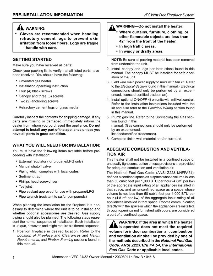
• Gloves are recommended when handling refractory cement logs to prevent skin irritation from loose fibers. Logs are fragile — handle with care.
WARNING: WARNING—Do not install the heater:• Where curtains, furniture, clothing, or
other flammable objects are less than 42" from the front of the heater.
• In high traffic areas.• In windy or drafty areas.
WARNING: If the area in which the heater is operated does not meet the required
volume for indoor combustion air, combustion and ventilation air shall be provided by one of the methods described in the National Fuel Gas Code, ANSI Z223.1/NFPA 54, the International Fuel Gas Code or applicable local codes.
NOTE: Be sure all packing material has been removed from underside the unit.
2. Install canopy and logs per instructions found in this manual. The canopy MUST be installed for safe oper-ation of the unit.
3. Field wire main power supply to units with fan kit. Refer to the Electrical Section found in this manual. (Electrical connections should only be performed by an experi-enced, licensed certified tradesman).
4. Install optional ON/OFF kit on units with millivolt control. Refer to the installation instructions included with the kit and also refer to the Electrical Wiring section found in this manual.
5. Plumb gas line. Refer to the Connecting the Gas sec-tion found in this manual. (Gas connections should only be performed by an experienced, licensed/certified tradesman).
6. Complete finish wall material and/or surround.
ADEQUATE COMBUSTION AND VENTILA-TION AIRThis heater shall not be installed in a confined space or unusually tight construction unless provisions are provided for adequate combustion and ventilation air.The National Fuel Gas Code, (ANSI Z223.1/NFPA54), defines a confined space as a space whose volume is less than 50 cubic feet per 1,000 BTU per hour (4.8m3 per kw) of the aggregate input rating of all appliances installed in that space, and an unconfined space as a space whose volume is not less than 50 cubic feet per 1,000 BTU per hour (4.8 m3 per kw) of the aggregate input rating of all appliances installed in that space. Rooms communicating directly with the space in which the appliances are installed, through openings not furnished with doors, are considered a part of a confined space.
9
VFC Vent Free Fireplace System
Monessen • VFC 24/32 Owner Manual • 20308011 • Rev B • 04/18
FIREPLACE INSTALLATION
FIREPLACE LOCATIONCarefully select the best location for installation of your unvented fireplace. The following factors should be taken into consideration.
• Clearance to side wall, ceiling, woodwork and window or other combustibles. Refer to “Clearances” section. Minimum clearances to combustibles must be maintained.
• Location must not be affected by drafts caused by kitchen exhaust fans, ceiling fans, return air registers for forced air furnaces / air conditioners, windows or doors.
• Installation must provide adequate ventilation and combustion air.
• DO NOT INSTALL THESE MODELS IN A BED-ROOM OR BATHROOM.
• Location should be out of high traffic areas and away from furniture and draperies due to heat from firebox.
• Never obstruct the front opening of the unvented fireplace or restrict the flow of combustion and ven-tilation air.
• Minimize modifications to existing construction. Refer to Figure 5 below for location suggestions.
• Do not install in the vicinity where gasoline or other flammable liquids may be stored. The unvented fire-box must be kept clear and free from the combustible materials.
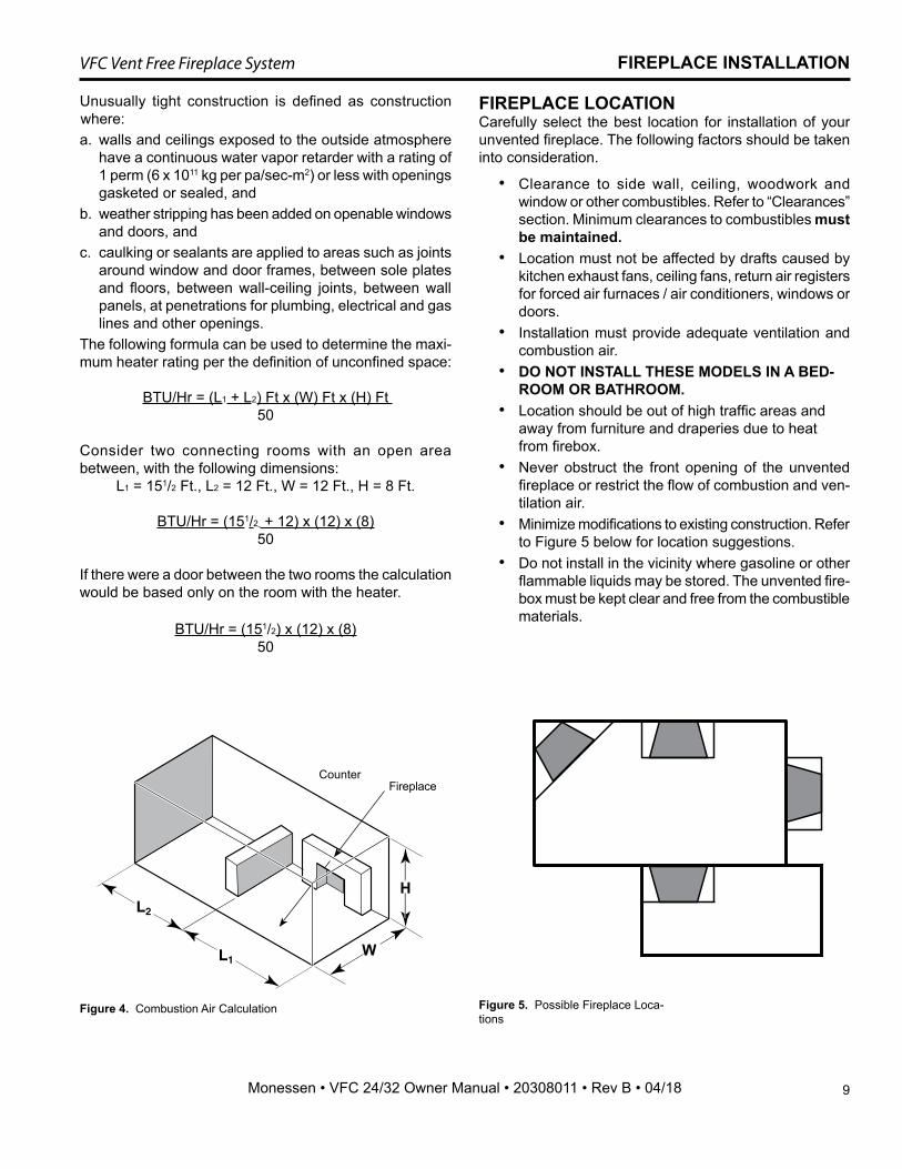
FP2440fireplace locations
W
H
CounterFireplace
Unusually tight construction is defined as construction where: a. walls and ceilings exposed to the outside atmosphere
have a continuous water vapor retarder with a rating of 1 perm (6 x 10¹¹ kg per pa/sec-m2) or less with openings gasketed or sealed, and
b. weather stripping has been added on openable windows and doors, and
c. caulking or sealants are applied to areas such as joints around window and door frames, between sole plates and floors, between wall-ceiling joints, between wall panels, at penetrations for plumbing, electrical and gas lines and other openings.
The following formula can be used to determine the maxi-mum heater rating per the definition of unconfined space:
BTU/Hr = (L1 + L2) Ft x (W) Ft x (H) Ft 50
Consider two connecting rooms with an open area between, with the following dimensions:
L1 = 151/2 Ft., L2 = 12 Ft., W = 12 Ft., H = 8 Ft.
BTU/Hr = (151/2 + 12) x (12) x (8)50
If there were a door between the two rooms the calculation would be based only on the room with the heater.
BTU/Hr = (151/2) x (12) x (8)50
Figure 4. Combustion Air Calculation Figure 5. Possible Fireplace Loca-tions
10
VFC Vent Free Fireplace System
Monessen • VFC 24/32 Owner Manual • 20308011 • Rev B • 04/18
FIREPLACE INSTALLATION
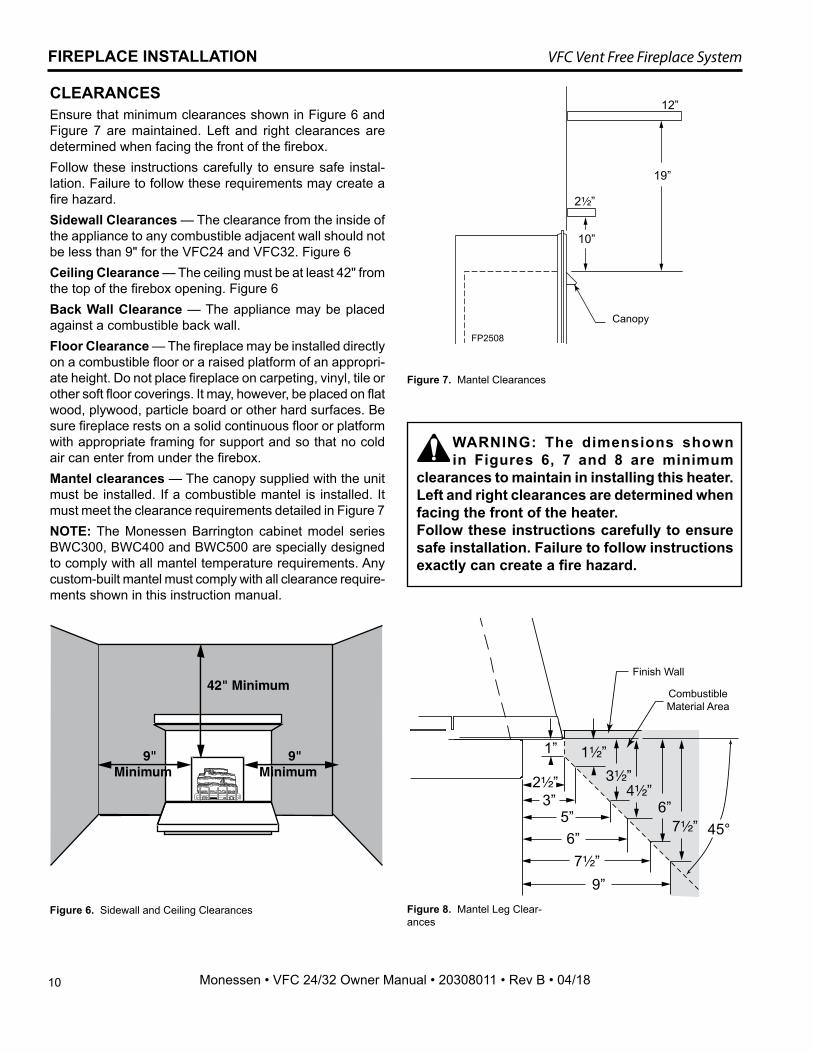
2¹⁄₂”
12”
10”
19”
FP2508VFS DBX mantel clearances
Canopy
FP2508
Figure 7. Mantel Clearances
WARNING: The dimensions shown in Figures 6, 7 and 8 are minimum
clearances to maintain in installing this heater. Left and right clearances are determined when facing the front of the heater. Follow these instructions carefully to ensure safe installation. Failure to follow instructions exactly can create a fire hazard.
CLEARANCES Ensure that minimum clearances shown in Figure 6 and Figure 7 are maintained. Left and right clearances are determined when facing the front of the firebox.Follow these instructions carefully to ensure safe instal-lation. Failure to follow these requirements may create a fire hazard.Sidewall Clearances — The clearance from the inside of the appliance to any combustible adjacent wall should not be less than 9" for the VFC24 and VFC32. Figure 6Ceiling Clearance — The ceiling must be at least 42" from the top of the firebox opening. Figure 6Back Wall Clearance — The appliance may be placed against a combustible back wall.Floor Clearance — The fireplace may be installed directly on a combustible floor or a raised platform of an appropri-ate height. Do not place fireplace on carpeting, vinyl, tile or other soft floor coverings. It may, however, be placed on flat wood, plywood, particle board or other hard surfaces. Be sure fireplace rests on a solid continuous floor or platform with appropriate framing for support and so that no cold air can enter from under the firebox. Mantel clearances — The canopy supplied with the unit must be installed. If a combustible mantel is installed. It must meet the clearance requirements detailed in Figure 7 NOTE: The Monessen Barrington cabinet model series BWC300, BWC400 and BWC500 are specially designed to comply with all mantel temperature requirements. Any custom-built mantel must comply with all clearance require-ments shown in this instruction manual.
9"Minimum
9"Minimum
42" Minimum
FP2441sidewall clg clear
Figure 6. Sidewall and Ceiling Clearances Figure 8. Mantel Leg Clear-ances
45°
1”
2¹⁄₂”3”
5”
6”
1¹⁄₂”
3¹⁄₂”4¹⁄₂”
FP2692mantel leg clearance
6”7¹⁄₂”
7¹⁄₂”
9”
Finish Wall
Combustible Material Area
11
VFC Vent Free Fireplace System
Monessen • VFC 24/32 Owner Manual • 20308011 • Rev B • 04/18
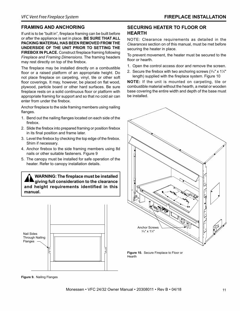
FP2509nailing flanges
Nail Sides Through Nailing Flanges
Figure 9. Nailing Flanges
FIREPLACE INSTALLATION
SECURING HEATER TO FLOOR OR HEARTHNOTE: Clearance requirements as detailed in the Clearances section on of this manual, must be met before securing the heater in place.To prevent movement, the heater must be secured to the floor or hearth.1. Open the control access door and remove the screen.2. Secure the firebox with two anchoring screws (3⁄16" x 11⁄4"
length) supplied with the fireplace system. Figure 10NOTE: If the unit is mounted on carpeting, tile or combustible material without the hearth, a metal or wooden base covering the entire width and depth of the base must be installed.
Figure 10. Secure Fireplace to Floor or Hearth
FRAMING AND ANCHORINGIf unit is to be “built in”, fireplace framing can be built before or after the appliance is set in place. BE SURE THAT ALL PACKING MATERIAL HAS BEEN REMOVED FROM THE UNDERSIDE OF THE UNIT PRIOR TO SETTING THE FIREBOX IN PLACE. Construct fireplace framing following Fireplace and Framing Dimensions. The framing headers may rest directly on top of the firebox.The fireplace may be installed directly on a combustible floor or a raised platform of an appropriate height. Do not place fireplace on carpeting, vinyl, tile or other soft floor coverings. It may, however, be placed on flat wood, plywood, particle board or other hard surfaces. Be sure fireplace rests on a solid continuous floor or platform with appropriate framing for support and so that no cold air can enter from under the firebox.Anchor fireplace to the side framing members using nailing flanges.1. Bend out the nailing flanges located on each side of the
firebox.2. Slide the firebox into prepared framing or position firebox
in its final position and frame later.3. Level the firebox by checking the top edge of the firebox.
Shim if necessary.4. Anchor firebox to the side framing members using 8d
nails or other suitable fasteners. Figure 95. The canopy must be installed for safe operation of the
heater. Refer to canopy installation details.
WARNING: The fireplace must be installed giving full consideration to the clearance
and height requirements identified in this manual.
Anchor Screws 3⁄16" x 11⁄4"
FP2781millivolt valve
Test Port"OUT"
12
VFC Vent Free Fireplace System
Monessen • VFC 24/32 Owner Manual • 20308011 • Rev B • 04/18
CONNECTING THE GAS LINE
NOTICE: A qualified gas appliance installer must connect the heater to the gas supply. Consult all local codes.
GAS LINE & PRESSURE
FP2447gas connection
3” Min.
To Fireplace
Pipe Coupling
Stainless Flexible Tube
PipeLocations Pressure Tapping Point Instal-lation
Manual Shutoff Valve
Gas Supply Inlet
Figure 11. Gas Connection
IMPORTANT: Loosen the pipe adapter on the flex tube before installing to the system piping.Always use an external regulator for all propane/LPG heat-ers only, to reduce the supply tank pressure to a maximum of 13" w.c. This is in addition to the internal regulator in the heater valve.To reach factory installed flex line, go through access door on right or left side of firebox.
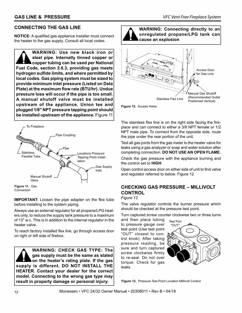
Figure 12. Access Holes
Manual Gas Shutoff(Recommended Outlet Positioned Vertical)
Stainless Flex Line
Access Door for Gas Line
WARNING: Connecting directly to an unregulated propane/LPG tank can cause an explosion
WARNING: Use new black iron or steel pipe. Internally tinned copper or copper tubing can be used per National
Fuel Code, section 2.6.3, providing gas meets hydrogen sulfide limits, and where permitted by local codes. Gas piping system must be sized to provide minimum inlet pressure (Listed on Data Plate) at the maximum flow rate (BTU/hr). Undue pressure loss will occur if the pipe is too small.A manual shutoff valve must be installed upstream of the appliance. Union tee and plugged 1/8" NPT pressure tapping point should be installed upstream of the appliance. Figure 11
WARNING: CHECK GAS TYPE: The gas supply must be the same as stated on the heater’s rating plate. If the gas
supply is different, DO NOT INSTALL THE HEATER. Contact your dealer for the correct model. Connecting to the wrong gas type may result in property damage or personal injury.
The stainless flex line is on the right side facing the fire-place and can connect to either a 3/8 NPT female or 1/2 NPT male pipe. To connect from the opposite side, route the pipe under the rear portion of the unit. Test all gas joints from the gas meter to the heater valve for leaks using a gas analyzer or soap and water solution after completing connection. DO NOT USE AN OPEN FLAME.Check the gas pressure with the appliance burning and the control set to HIGH.Open control access door on either side of unit to find valve and regulator referred to below. Figure 12
CHECKING GAS PRESSURE – MILLIVOLT CONTROL Figure 12The valve regulator controls the burner pressure which should be checked at the pressure test point.Turn captured screw counter clockwise two or three turns and then place tubing to pressure gauge over test point (Use test point “OUT” closest to con-trol knob). After taking pressure reading, be sure and turn captured screw clockwise firmly to re-seal. Do not over torque. Check for gas leaks.
Figure 13. Pressure Test Point Location Millivolt Control
13
VFC Vent Free Fireplace System
Monessen • VFC 24/32 Owner Manual • 20308011 • Rev B • 04/18
CHECK GAS PRESSURE – IPI1. Check gas type. The gas supply must be the same as
stated on the appliance’s rating decal. If the gas supply is different from the fireplace, STOP! Do not install the appliance. Contact your dealer immediately.
2. To facilitate easier installation, a 18" (610 mm) flex line with manual shut-off valve has been provided with this appliance. Install and attach 1/2" gas line onto shut-off valve.
3. After completing gas line connection, purge air from gas line and test all gas joints from the gas meter to the fireplace for leaks. Use a solution of 50/50 water and soap solution or a gas sniffer.
4. To check gas pressures at valve, turn captured screw counter clockwise 2 or 3 turns and then place tubing to pressure gauge over test point. Turn unit to high. Fig-ure 14 After taking pressure reading, be sure and turn captured screw clockwise firmly to reseal. Do not over torque. Check test points for gas leaks.
Figure 14. IPI Valve
FP3034IPI gas valve
Pressure Inlet
Pilot Adjust-ment Screw
Pressure Outlet
FP3034
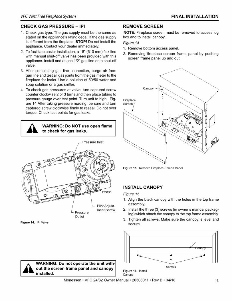
FINAL INSTALLATION
REMOVE SCREENNOTE: Fireplace screen must be removed to access log box and to install canopy. Figure 141. Remove bottom access panel. 2. Removing fireplace screen frame panel by pushing
screen frame panel up and out.
INSTALL CANOPYFigure 151. Align the black canopy with the holes in the top frame
assembly. 2. Install the three (3) screws (in owner’s manual packag-
ing) which attach the canopy to the top frame assembly.3. Tighten all screws. Make sure the canopy is level and
secure.
Canopy
WARNING: Do not operate the unit with-out the screen frame panel and canopy installed.
Screws
Fireplace Screen
Canopy
WARNING: Do NOT use open flame to check for gas leaks.
Figure 15. Remove Fireplace Screen Panel
Figure 16. Install Canopy
14
VFC Vent Free Fireplace System
Monessen • VFC 24/32 Owner Manual • 20308011 • Rev B • 04/18
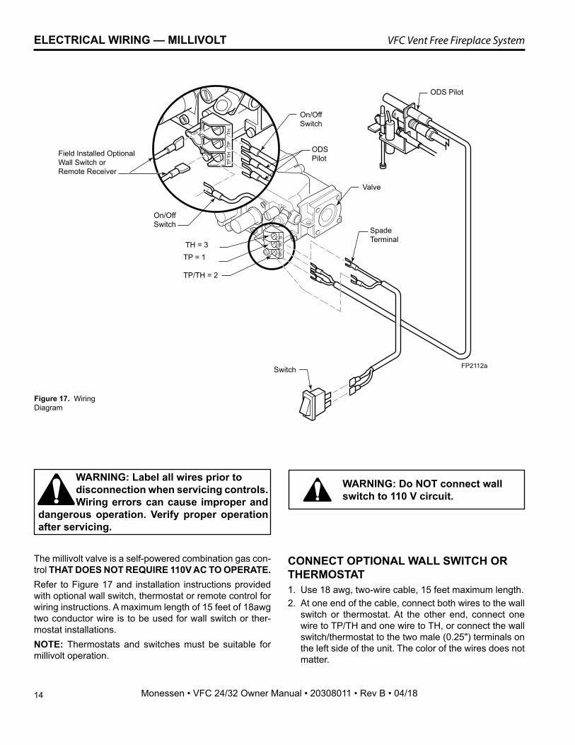
Figure 17. Wiring Diagram
FP2112awiring diagram8/09
Field Installed Optional Wall Switch or Remote Receiver
Switch
On/OffSwitch
On/OffSwitch
ODS Pilot
Valve
ODS Pilot
Spade Terminal
FP2112a
TH = 3TP = 1
TP/TH = 2
The millivolt valve is a self-powered combination gas con-trol THAT DOES NOT REQUIRE 110V AC TO OPERATE.Refer to Figure 17 and installation instructions provided with optional wall switch, thermostat or remote control for wiring instructions. A maximum length of 15 feet of 18awg two conductor wire is to be used for wall switch or ther-mostat installations. NOTE: Thermostats and switches must be suitable for millivolt operation.
CONNECT OPTIONAL WALL SWITCH OR THERMOSTAT1. Use 18 awg, two-wire cable, 15 feet maximum length.2. At one end of the cable, connect both wires to the wall
switch or thermostat. At the other end, connect one wire to TP/TH and one wire to TH, or connect the wall switch/thermostat to the two male (0.25") terminals on the left side of the unit. The color of the wires does not matter.
WARNING: Do NOT connect wall switch to 110 V circuit.
WARNING: Label all wires prior to disconnection when servicing controls. Wiring errors can cause improper and dangerous operation. Verify proper operation after servicing.
ELECTRICAL WIRING — MILLIVOLT
15
VFC Vent Free Fireplace System
Monessen • VFC 24/32 Owner Manual • 20308011 • Rev B • 04/18
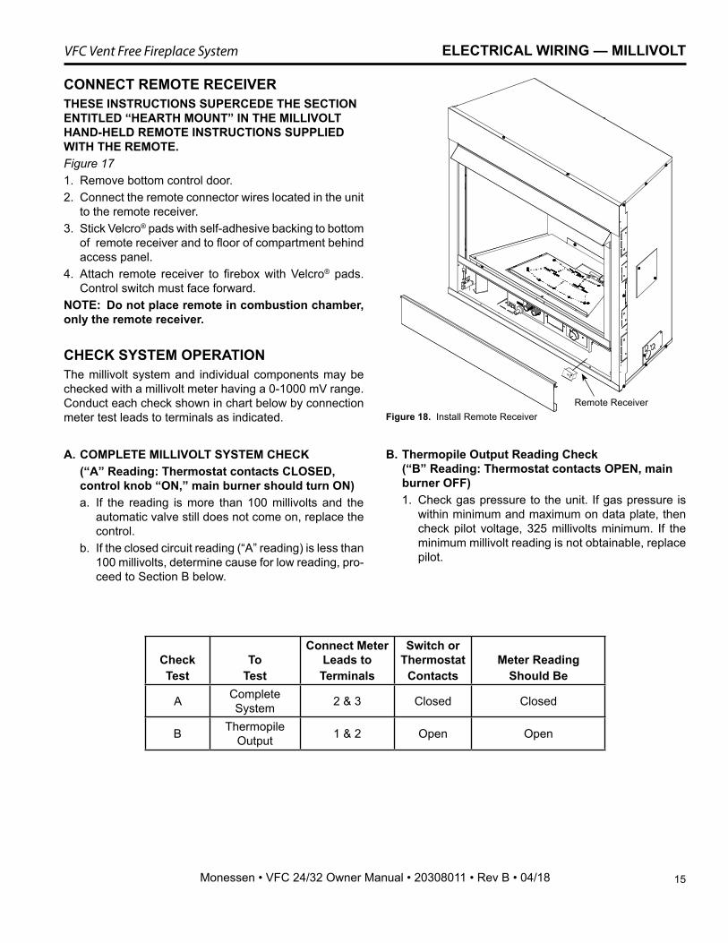
Figure 18. Install Remote Receiver
CheckTest
ToTest
Connect Meter Leads toTerminals
Switch or Thermostat
ContactsMeter Reading
Should Be
A Complete System 2 & 3 Closed Closed
B Thermopile Output 1 & 2 Open Open
CONNECT REMOTE RECEIVERTHESE INSTRUCTIONS SUPERCEDE THE SECTION ENTITLED “HEARTH MOUNT” IN THE MILLIVOLT HAND-HELD REMOTE INSTRUCTIONS SUPPLIED WITH THE REMOTE.Figure 171. Remove bottom control door. 2. Connect the remote connector wires located in the unit
to the remote receiver.3. Stick Velcro® pads with self-adhesive backing to bottom
of remote receiver and to floor of compartment behind access panel.
4. Attach remote receiver to firebox with Velcro® pads. Control switch must face forward.
NOTE: Do not place remote in combustion chamber, only the remote receiver.
CHECK SYSTEM OPERATIONThe millivolt system and individual components may be checked with a millivolt meter having a 0-1000 mV range. Conduct each check shown in chart below by connection meter test leads to terminals as indicated.
A. COMPLETE MILLIVOLT SYSTEM CHECK (“A” Reading: Thermostat contacts CLOSED,
control knob “ON,” main burner should turn ON)a. If the reading is more than 100 millivolts and the
automatic valve still does not come on, replace the control.
b. If the closed circuit reading (“A” reading) is less than 100 millivolts, determine cause for low reading, pro-ceed to Section B below.
B. Thermopile Output Reading Check (“B” Reading: Thermostat contacts OPEN, main burner OFF)1. Check gas pressure to the unit. If gas pressure is
within minimum and maximum on data plate, then check pilot voltage, 325 millivolts minimum. If the minimum millivolt reading is not obtainable, replace pilot.
ELECTRICAL WIRING — MILLIVOLT
Remote Receiver
16
VFC Vent Free Fireplace System
Monessen • VFC 24/32 Owner Manual • 20308011 • Rev B • 04/18
OPERATING INSTRUCTIONS—MILLIVOLT
A. This appliance is equipped with a pilot which must be lit with built-in piezo ignitor while following these instructions exactly.
B. BEFORE OPERATING smell all around the appliance area for gas. Be sure to smell next to the floor because some gas is heavier than air and will settle on the floor.
WHAT TO DO IF YOU SMELL GAS: • Turn off all gas to the appliance. • Open windows. • Do not attempt to light any appliance. • Do not touch any electric switch; do not use any phone in your building. • Immediately call your gas supplier from a neighbor's phone. Follow the gas supplier's instructions. • If you cannot reach your gas supplier, call the fire department.C. Use only your hand to push in, or turn the gas control knob. Never use tools. If the knob will not push
in or turn by hand, don't try to repair it. Call a qualified service technician. Force or attempted repair may result in a fire or explosion.
D. Do not use this appliance if any part of it has been under water. Immediately call a qualified service technician to inspect the appliance and to replace any part of the control system and any gas control that has been under water.
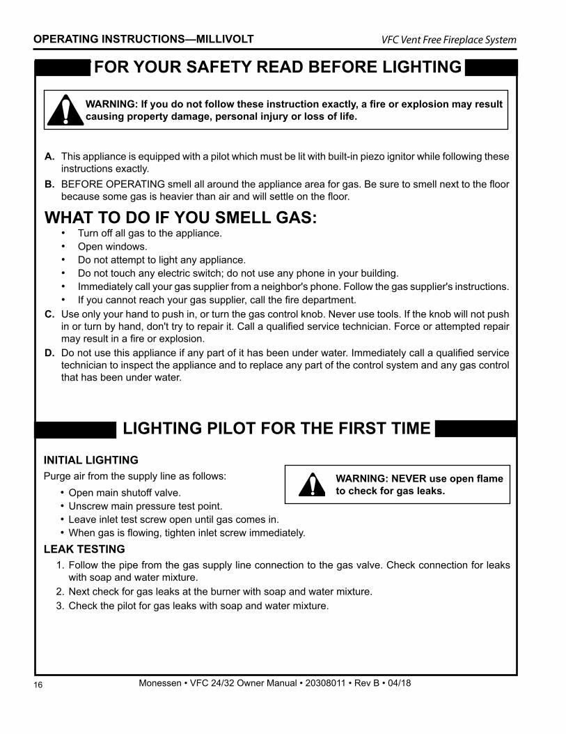
FOR YOUR SAFETY READ BEFORE LIGHTING
LIGHTING PILOT FOR THE FIRST TIME
INITIAL LIGHTING Purge air from the supply line as follows:
• Open main shutoff valve. • Unscrew main pressure test point. • Leave inlet test screw open until gas comes in. • When gas is flowing, tighten inlet screw immediately.
LEAK TESTING1. Follow the pipe from the gas supply line connection to the gas valve. Check connection for leaks
with soap and water mixture. 2. Next check for gas leaks at the burner with soap and water mixture.3. Check the pilot for gas leaks with soap and water mixture.
WARNING: If you do not follow these instruction exactly, a fire or explosion may result causing property damage, personal injury or loss of life.
WARNING: NEVER use open flame to check for gas leaks.
17
VFC Vent Free Fireplace System
Monessen • VFC 24/32 Owner Manual • 20308011 • Rev B • 04/18
OPERATING INSTRUCTIONS—MILLIVOLT
PILOT
OFF
P
ILO
T
ON
FP1935control knob pilot
Continued on next page
APPROVED LEAK TESTING METHOD You may check for gas leaks with the following methods only:
• Soap and water solution• An approved leak testing spray• Electronic sniffer
NOTE: Remove any excessive pipe compound from the connections. Excessive pipe compound can set off electronic sniffers.
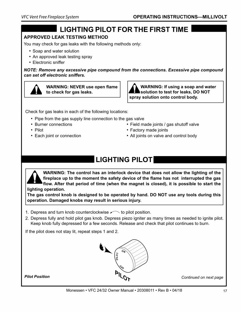
1. Depress and turn knob counterclockwise to pilot position. 2. Depress fully and hold pilot gas knob. Depress piezo igniter as many times as needed to ignite pilot.
Keep knob fully depressed for a few seconds. Release and check that pilot continues to burn.
If the pilot does not stay lit, repeat steps 1 and 2.
LIGHTING PILOT
Pilot Position
Check for gas leaks in each of the following locations: • Pipe from the gas supply line connection to the gas valve • Burner connections • Field made joints / gas shutoff valve • Pilot • Factory made joints • Each joint or connection • All joints on valve and control body
LIGHTING PILOT FOR THE FIRST TIME
WARNING: NEVER use open flame to check for gas leaks.
WARNING: If using a soap and water solution to test for leaks, DO NOT
spray solution onto control body.
WARNING: The control has an interlock device that does not allow the lighting of the fireplace up to the moment the safety device of the flame has not interrupted the gas flow. After that period of time (when the magnet is closed), it is possible to start the
lighting operation. The gas control knob is designed to be operated by hand. DO NOT use any tools during this operation. Damaged knobs may result in serious injury.
18
VFC Vent Free Fireplace System
Monessen • VFC 24/32 Owner Manual • 20308011 • Rev B • 04/18
PILOT
OFF
PILOT
ON
Wall Switch
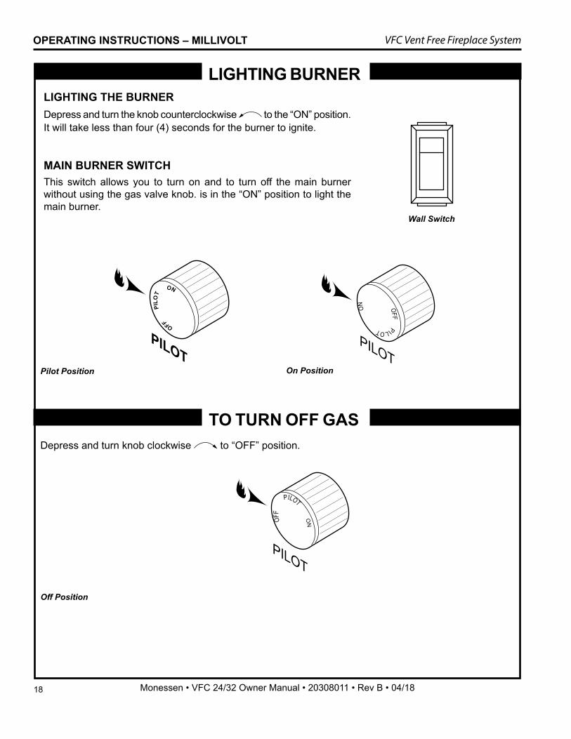
LIGHTING BURNER LIGHTING THE BURNERDepress and turn the knob counterclockwise to the “ON” position. It will take less than four (4) seconds for the burner to ignite.
MAIN BURNER SWITCH This switch allows you to turn on and to turn off the main burner without using the gas valve knob. is in the “ON” position to light the main burner.
Depress and turn knob clockwise to “OFF” position.
TO TURN OFF GAS
Off Position
FP3033wall switch
PILOT
OFF
P
ILO
T
ON
FP1935control knob pilot
OFF PILOT
ON
PILOT
FP1937control knob on
Pilot Position On Position
OPERATING INSTRUCTIONS – MILLIVOLT
19
VFC Vent Free Fireplace System
Monessen • VFC 24/32 Owner Manual • 20308011 • Rev B • 04/18
ELECTRICAL WIRING General1. This fireplace is equipped with an IPI control valve which
operates on 6 volts. The 6 volt DC adapter plugs into the fireplace junction box A/C power supply.
2. The IPI system can also be operated without A/C power. The system can run on four (4) “AA” batteries using the optional battery backup for approximately six (6) months under normal use.
Optional AccessoriesThis fireplace may be used with a wall switch, wall mounted thermostat or IPI hand held remote control.
CA
UTI
ON Label all wires before disconnecting when
servicing controls. Wiring errors can cause improper and dangerous operation.
ELECTRICAL INSTALLATION — IPI
WARNING: Electrical connections should only be performed by a qualified, licensed electrician. Main power must be off
when connecting to main electrical power supply or performing service. All wiring shall be in compliance with all local, city and state codes. The appliance, when installed, must be electrically grounded in accordance with local codes or in the absence of local codes, with the National Electrical Code ANSI/NFPA 70 (latest edition) and Canadian Electrical Code, CSA C22.1.
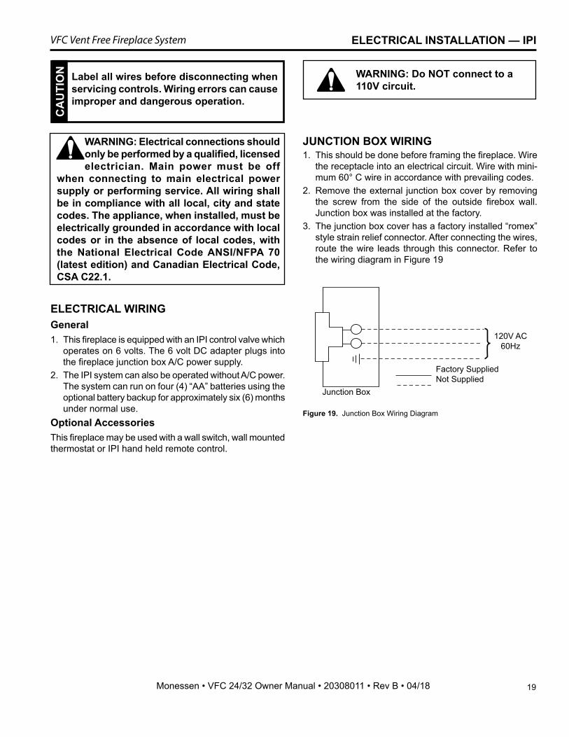
Figure 19. Junction Box Wiring Diagram
FP1912 Junction box wiring 8/08
Junction Box
Factory SuppliedNot Supplied
120V AC60Hz
WARNING: Do NOT connect to a 110V circuit.
JUNCTION BOX WIRING1. This should be done before framing the fireplace. Wire
the receptacle into an electrical circuit. Wire with mini-mum 60° C wire in accordance with prevailing codes.
2. Remove the external junction box cover by removing the screw from the side of the outside firebox wall. Junction box was installed at the factory.
3. The junction box cover has a factory installed “romex” style strain relief connector. After connecting the wires, route the wire leads through this connector. Refer to the wiring diagram in Figure 19
20
VFC Vent Free Fireplace System
Monessen • VFC 24/32 Owner Manual • 20308011 • Rev B • 04/18
RED
RED
RED
RED
RED
BLAC
K
D/C
PO
WER
GRE
EN
GRO
UN
D
BROWN
BLACK
BLACK
ORANGEYELLOWBLACK
BLACK
RED
CA
UTI
ON Electrical connections should only be performed by a qualified, licensed electrician. Main
power supply must be turned off before connecting fans to the main electrical power supply or performing service.
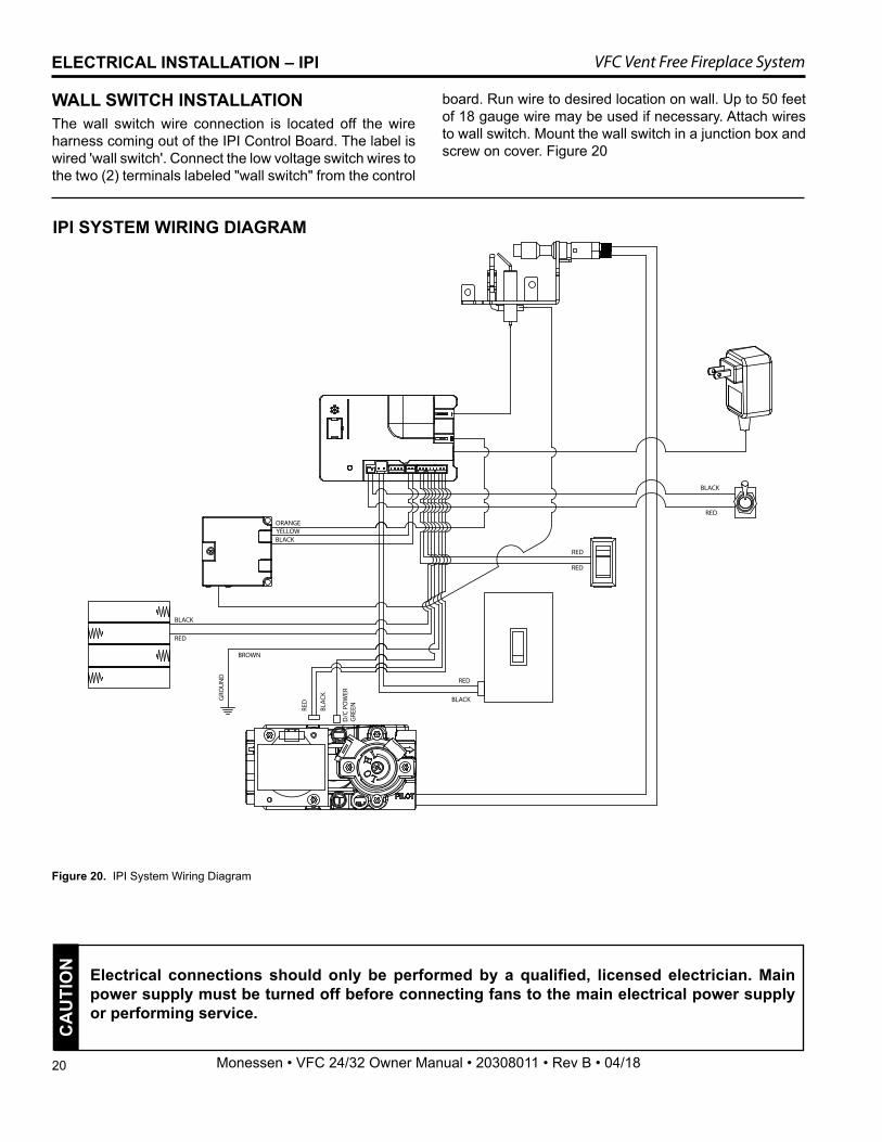
Figure 20. IPI System Wiring Diagram
IPI SYSTEM WIRING DIAGRAM
ELECTRICAL INSTALLATION – IPI
WALL SWITCH INSTALLATIONThe wall switch wire connection is located off the wire harness coming out of the IPI Control Board. The label is wired 'wall switch'. Connect the low voltage switch wires to the two (2) terminals labeled "wall switch" from the control
board. Run wire to desired location on wall. Up to 50 feet of 18 gauge wire may be used if necessary. Attach wires to wall switch. Mount the wall switch in a junction box and screw on cover. Figure 20
21
VFC Vent Free Fireplace System
Monessen • VFC 24/32 Owner Manual • 20308011 • Rev B • 04/18
OPERATING INSTRUCTIONS – IPI
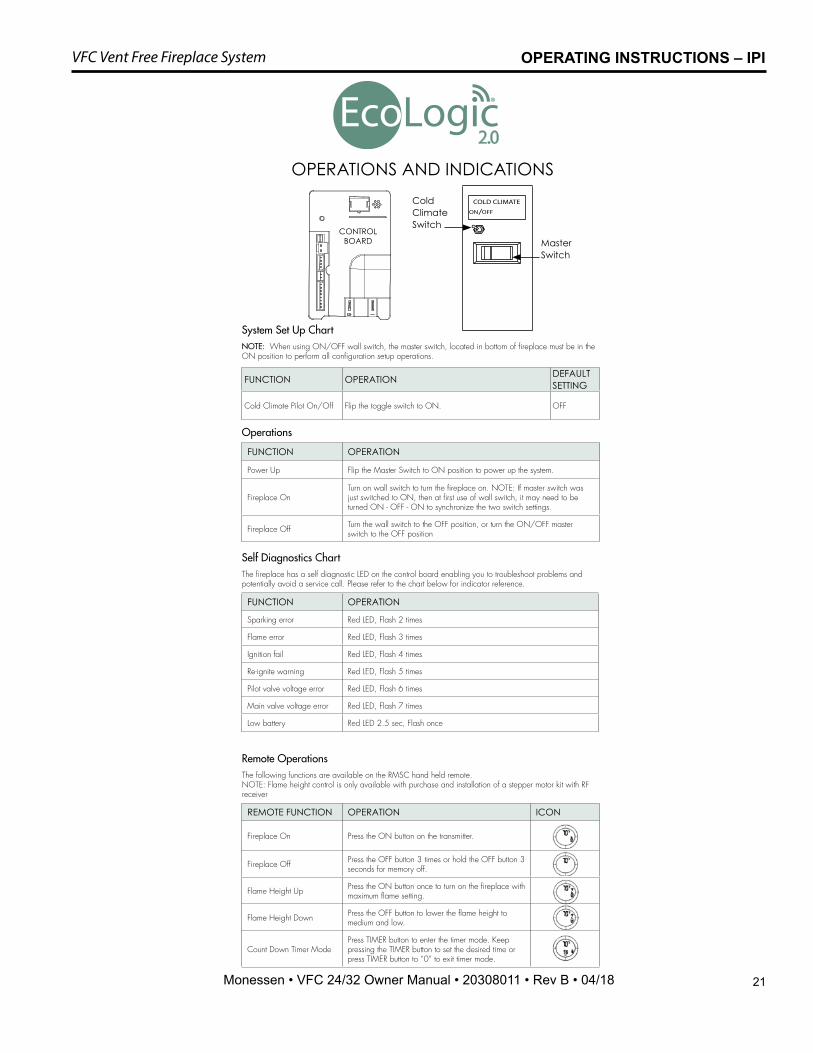
OPERATIONS AND INDICATIONS
System Set Up ChartNOTE: When using ON/OFF wall switch, the master switch, located in bottom of fireplace must be in the ON position to perform all configuration setup operations.
Self Diagnostics ChartThe fireplace has a self diagnostic LED on the control board enabling you to troubleshoot problems and potentially avoid a service call. Please refer to the chart below for indicator reference.
Remote OperationsThe following functions are available on the RMSC hand held remote. NOTE: Flame height control is only available with purchase and installation of a stepper motor kit with RF receiver
Operations
FUNCTION OPERATION DEFAULT SETTING
Cold Climate Pilot On/Off Flip the toggle switch to ON. OFF
FUNCTION OPERATION
Sparking error Red LED, Flash 2 times
Flame error Red LED, Flash 3 times
Ignition fail Red LED, Flash 4 times
Re-ignite warning Red LED, Flash 5 times
Pilot valve voltage error Red LED, Flash 6 times
Main valve voltage error Red LED, Flash 7 times
Low battery Red LED 2.5 sec, Flash once
REMOTE FUNCTION OPERATION ICON
Fireplace On Press the ON button on the transmitter.
Fireplace Off Press the OFF button 3 times or hold the OFF button 3 seconds for memory off.
Flame Height Up Press the ON button once to turn on the fireplace with maximum flame setting.
Flame Height Down Press the OFF button to lower the flame height to medium and low.
Count Down Timer ModePress TIMER button to enter the timer mode. Keep pressing the TIMER button to set the desired time or press TIMER button to “0” to exit timer mode.
FUNCTION OPERATION
Power Up Flip the Master Switch to ON position to power up the system.
Fireplace OnTurn on wall switch to turn the fireplace on. NOTE: If master switch was just switched to ON, then at first use of wall switch, it may need to be turned ON - OFF - ON to synchronize the two switch settings.
Fireplace Off Turn the wall switch to the OFF position, or turn the ON/OFF master switch to the OFF position
Cold Climate Switch
Master Switch
®
2.0
CONTROL BOARD
22
VFC Vent Free Fireplace System
Monessen • VFC 24/32 Owner Manual • 20308011 • Rev B • 04/18
OPERATING INSTRUCTIONS – IPI
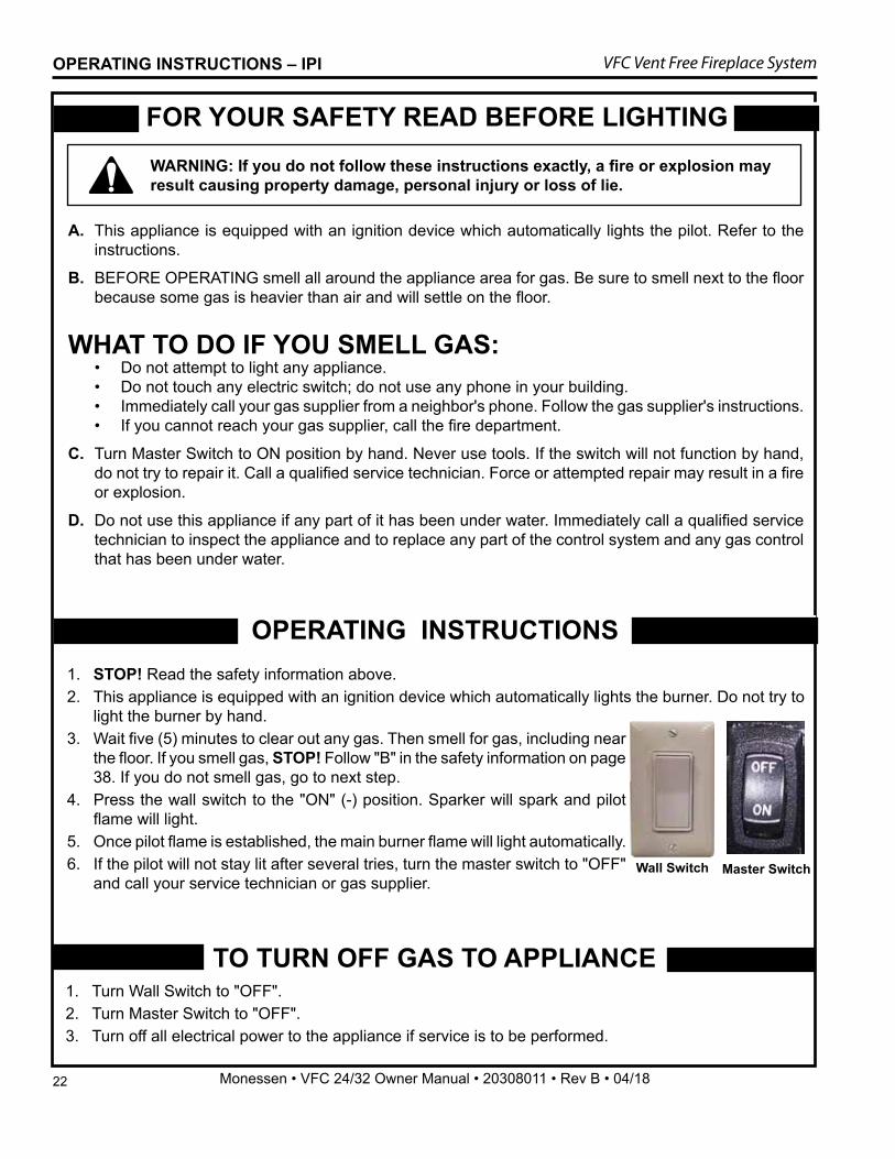
A. This appliance is equipped with an ignition device which automatically lights the pilot. Refer to the instructions.
B. BEFORE OPERATING smell all around the appliance area for gas. Be sure to smell next to the floor because some gas is heavier than air and will settle on the floor.
WHAT TO DO IF YOU SMELL GAS: • Do not attempt to light any appliance. • Do not touch any electric switch; do not use any phone in your building. • Immediately call your gas supplier from a neighbor's phone. Follow the gas supplier's instructions. • If you cannot reach your gas supplier, call the fire department.
C. Turn Master Switch to ON position by hand. Never use tools. If the switch will not function by hand, do not try to repair it. Call a qualified service technician. Force or attempted repair may result in a fire or explosion.
D. Do not use this appliance if any part of it has been under water. Immediately call a qualified service technician to inspect the appliance and to replace any part of the control system and any gas control that has been under water.
FOR YOUR SAFETY READ BEFORE LIGHTING WARNING: If you do not follow these instructions exactly, a fire or explosion may result causing property damage, personal injury or loss of lie.
TO TURN OFF GAS TO APPLIANCE1. Turn Wall Switch to "OFF".2. Turn Master Switch to "OFF".3. Turn off all electrical power to the appliance if service is to be performed.
OPERATING INSTRUCTIONS 1. STOP! Read the safety information above.2. This appliance is equipped with an ignition device which automatically lights the burner. Do not try to
light the burner by hand.3. Wait five (5) minutes to clear out any gas. Then smell for gas, including near
the floor. If you smell gas, STOP! Follow "B" in the safety information on page 38. If you do not smell gas, go to next step.
4. Press the wall switch to the "ON" (-) position. Sparker will spark and pilot flame will light.
5. Once pilot flame is established, the main burner flame will light automatically.6. If the pilot will not stay lit after several tries, turn the master switch to "OFF"
and call your service technician or gas supplier.
FP3045wall switch
Wall SwitchFP3046master switch
Master Switch
23
VFC Vent Free Fireplace System
Monessen • VFC 24/32 Owner Manual • 20308011 • Rev B • 04/18
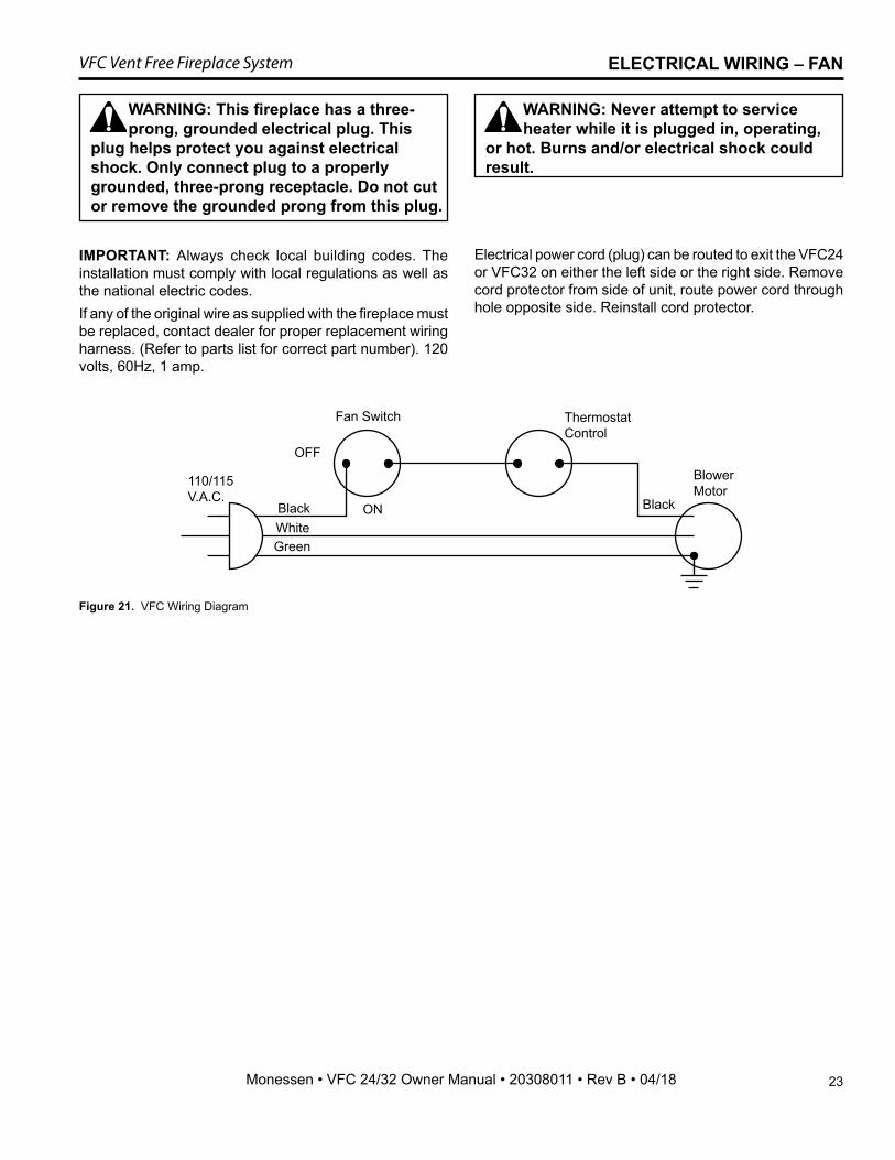
ELECTRICAL WIRING – FAN
IMPORTANT: Always check local building codes. The installation must comply with local regulations as well as the national electric codes.If any of the original wire as supplied with the fireplace must be replaced, contact dealer for proper replacement wiring harness. (Refer to parts list for correct part number). 120 volts, 60Hz, 1 amp.
110/115V.A.C.
Fan Switch
OFF
Black
White
Green
ON
ThermostatControl
BlowerMotor
Black
FP2783DIS wiring
Figure 21. VFC Wiring Diagram
Electrical power cord (plug) can be routed to exit the VFC24 or VFC32 on either the left side or the right side. Remove cord protector from side of unit, route power cord through hole opposite side. Reinstall cord protector.
WARNING: Never attempt to service heater while it is plugged in, operating,
or hot. Burns and/or electrical shock could result.
WARNING: This fireplace has a three-prong, grounded electrical plug. This
plug helps protect you against electrical shock. Only connect plug to a properly grounded, three-prong receptacle. Do not cut or remove the grounded prong from this plug.
24
VFC Vent Free Fireplace System
Monessen • VFC 24/32 Owner Manual • 20308011 • Rev B • 04/18
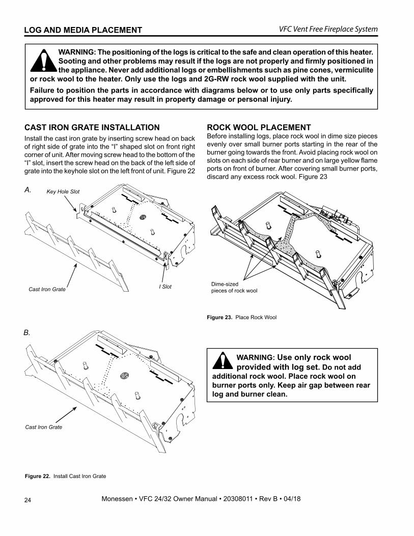
Figure 22. Install Cast Iron Grate
CAST IRON GRATE INSTALLATION Install the cast iron grate by inserting screw head on back of right side of grate into the “I” shaped slot on front right corner of unit. After moving screw head to the bottom of the “I” slot, insert the screw head on the back of the left side of grate into the keyhole slot on the left front of unit. Figure 22
WARNING: The positioning of the logs is critical to the safe and clean operation of this heater. Sooting and other problems may result if the logs are not properly and firmly positioned in the appliance. Never add additional logs or embellishments such as pine cones, vermiculite
or rock wool to the heater. Only use the logs and 2G-RW rock wool supplied with the unit. Failure to position the parts in accordance with diagrams below or to use only parts specifically approved for this heater may result in property damage or personal injury.
B.
Cast Iron Grate
A.
Cast Iron Grate I Slot
Key Hole Slot
LOG AND MEDIA PLACEMENT
Figure 23. Place Rock Wool
ROCK WOOL PLACEMENT Before installing logs, place rock wool in dime size pieces evenly over small burner ports starting in the rear of the burner going towards the front. Avoid placing rock wool on slots on each side of rear burner and on large yellow flame ports on front of burner. After covering small burner ports, discard any excess rock wool. Figure 23
Dime-sizedpieces of rock wool
WARNING: Use only rock wool provided with log set. Do not add additional rock wool. Place rock wool on burner ports only. Keep air gap between rear log and burner clean.
25
VFC Vent Free Fireplace System
Monessen • VFC 24/32 Owner Manual • 20308011 • Rev B • 04/18
LOG AND MEDIA PLACEMENT
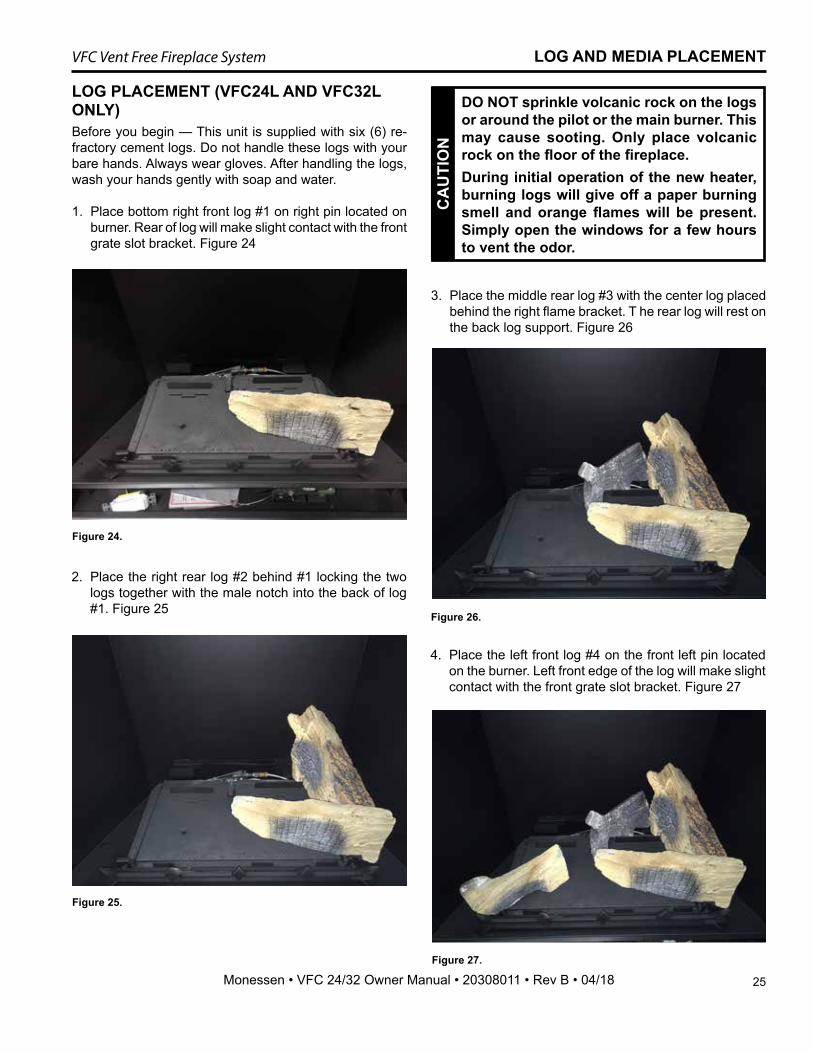
LOG PLACEMENT (VFC24L AND VFC32L ONLY)Before you begin — This unit is supplied with six (6) re-fractory cement logs. Do not handle these logs with your bare hands. Always wear gloves. After handling the logs, wash your hands gently with soap and water.
1. Place bottom right front log #1 on right pin located on burner. Rear of log will make slight contact with the front grate slot bracket. Figure 24
CA
UTI
ON
DO NOT sprinkle volcanic rock on the logs or around the pilot or the main burner. This may cause sooting. Only place volcanic rock on the floor of the fireplace.During initial operation of the new heater, burning logs will give off a paper burning smell and orange flames will be present. Simply open the windows for a few hours to vent the odor.
2. Place the right rear log #2 behind #1 locking the two logs together with the male notch into the back of log #1. Figure 25
3. Place the middle rear log #3 with the center log placed behind the right flame bracket. T he rear log will rest on the back log support. Figure 26
4. Place the left front log #4 on the front left pin located on the burner. Left front edge of the log will make slight contact with the front grate slot bracket. Figure 27
Figure 24.
Figure 25.
Figure 26.
Figure 27.
26
VFC Vent Free Fireplace System
Monessen • VFC 24/32 Owner Manual • 20308011 • Rev B • 04/18
LOG AND MEDIA PLACEMENT
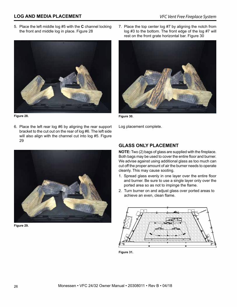
5. Place the left middle log #5 with the C channel locking the front and middle log in place. Figure 28
6. Place the left rear log #6 by aligning the rear support bracket to the cut out on the rear of log #6. The left side will also align with the channel cut into log #5. Figure 29
7. Place the top center log #7 by aligning the notch from log #3 to the bottom. The front edge of the log #7 will rest on the front grate horizontal bar. Figure 30
Log placement complete.
GLASS ONLY PLACEMENTNOTE: Two (2) bags of glass are supplied with the fireplace. Both bags may be used to cover the entire floor and burner. We advise against using additional glass as too much can cut off the proper amount of air the burner needs to operate cleanly. This may cause sooting.1. Spread glass evenly in one layer over the entire floor
and burner. Be sure to use a single layer only over the ported area so as not to impinge the flame.
2. Turn burner on and adjust glass over ported areas to achieve an even, clean flame.
Figure 28.
Figure 29.
Figure 30.
Figure 31.
27
VFC Vent Free Fireplace System
Monessen • VFC 24/32 Owner Manual • 20308011 • Rev B • 04/18
FLAME APPEARANCE
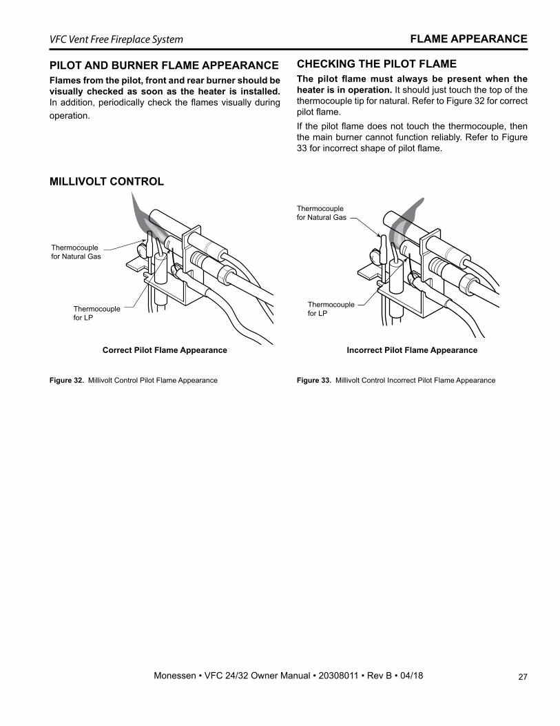
PILOT AND BURNER FLAME APPEARANCEFlames from the pilot, front and rear burner should be visually checked as soon as the heater is installed. In addition, periodically check the flames visually during operation.
Figure 32. Millivolt Control Pilot Flame Appearance
MILLIVOLT CONTROL
FP2273pilot bad flame
FP2272pilot correct flame
Thermocouple for Natural Gas
Thermocouple for LP
Thermocouple for Natural Gas
Thermocouple for LP
Correct Pilot Flame Appearance Incorrect Pilot Flame Appearance
CHECKING THE PILOT FLAMEThe pilot flame must always be present when the heater is in operation. It should just touch the top of the thermocouple tip for natural. Refer to Figure 32 for correct pilot flame. If the pilot flame does not touch the thermocouple, then the main burner cannot function reliably. Refer to Figure 33 for incorrect shape of pilot flame.
Figure 33. Millivolt Control Incorrect Pilot Flame Appearance
28
VFC Vent Free Fireplace System
Monessen • VFC 24/32 Owner Manual • 20308011 • Rev B • 04/18
FLAME APPEARANCE
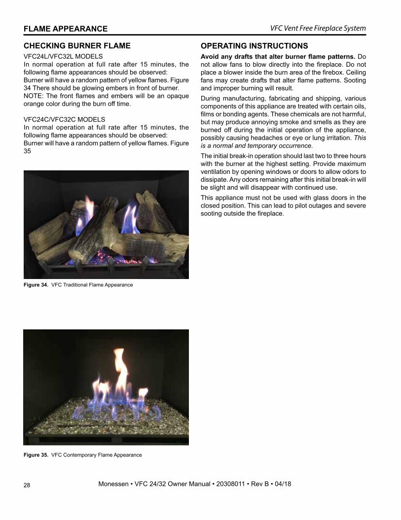
CHECKING BURNER FLAMEVFC24L/VFC32L MODELSIn normal operation at full rate after 15 minutes, the following flame appearances should be observed:Burner will have a random pattern of yellow flames. Figure 34 There should be glowing embers in front of burner.NOTE: The front flames and embers will be an opaque orange color during the burn off time.
VFC24C/VFC32C MODELSIn normal operation at full rate after 15 minutes, the following flame appearances should be observed:Burner will have a random pattern of yellow flames. Figure 35
Figure 34. VFC Traditional Flame Appearance
Figure 35. VFC Contemporary Flame Appearance
OPERATING INSTRUCTIONSAvoid any drafts that alter burner flame patterns. Do not allow fans to blow directly into the fireplace. Do not place a blower inside the burn area of the firebox. Ceiling fans may create drafts that alter flame patterns. Sooting and improper burning will result.During manufacturing, fabricating and shipping, various components of this appliance are treated with certain oils, films or bonding agents. These chemicals are not harmful, but may produce annoying smoke and smells as they are burned off during the initial operation of the appliance, possibly causing headaches or eye or lung irritation. This is a normal and temporary occurrence.The initial break-in operation should last two to three hours with the burner at the highest setting. Provide maximum ventilation by opening windows or doors to allow odors to dissipate. Any odors remaining after this initial break-in will be slight and will disappear with continued use.This appliance must not be used with glass doors in the closed position. This can lead to pilot outages and severe sooting outside the fireplace.
29
VFC Vent Free Fireplace System
Monessen • VFC 24/32 Owner Manual • 20308011 • Rev B • 04/18
Location of Piezo Ignitor, Control Knobs and Switch on Millivolt Unit, Hi/Lo Remote Control and Manual Unit
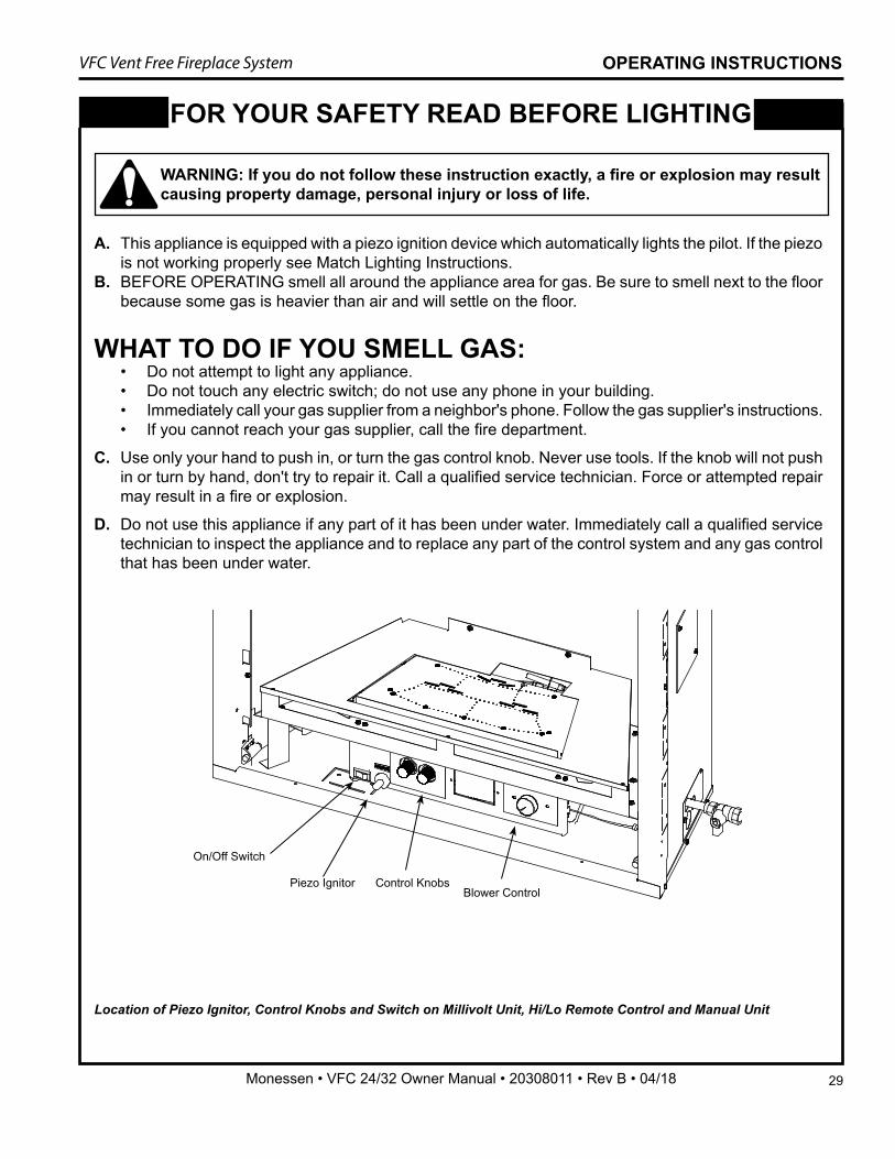
A. This appliance is equipped with a piezo ignition device which automatically lights the pilot. If the piezo is not working properly see Match Lighting Instructions.
B. BEFORE OPERATING smell all around the appliance area for gas. Be sure to smell next to the floor because some gas is heavier than air and will settle on the floor.
WHAT TO DO IF YOU SMELL GAS: • Do not attempt to light any appliance. • Do not touch any electric switch; do not use any phone in your building. • Immediately call your gas supplier from a neighbor's phone. Follow the gas supplier's instructions. • If you cannot reach your gas supplier, call the fire department.
C. Use only your hand to push in, or turn the gas control knob. Never use tools. If the knob will not push in or turn by hand, don't try to repair it. Call a qualified service technician. Force or attempted repair may result in a fire or explosion.
D. Do not use this appliance if any part of it has been under water. Immediately call a qualified service technician to inspect the appliance and to replace any part of the control system and any gas control that has been under water.
FOR YOUR SAFETY READ BEFORE LIGHTING
OPERATING INSTRUCTIONS
WARNING: If you do not follow these instruction exactly, a fire or explosion may result causing property damage, personal injury or loss of life.
Piezo Ignitor Control Knobs
On/Off Switch
Blower Control
30
VFC Vent Free Fireplace System
Monessen • VFC 24/32 Owner Manual • 20308011 • Rev B • 04/18
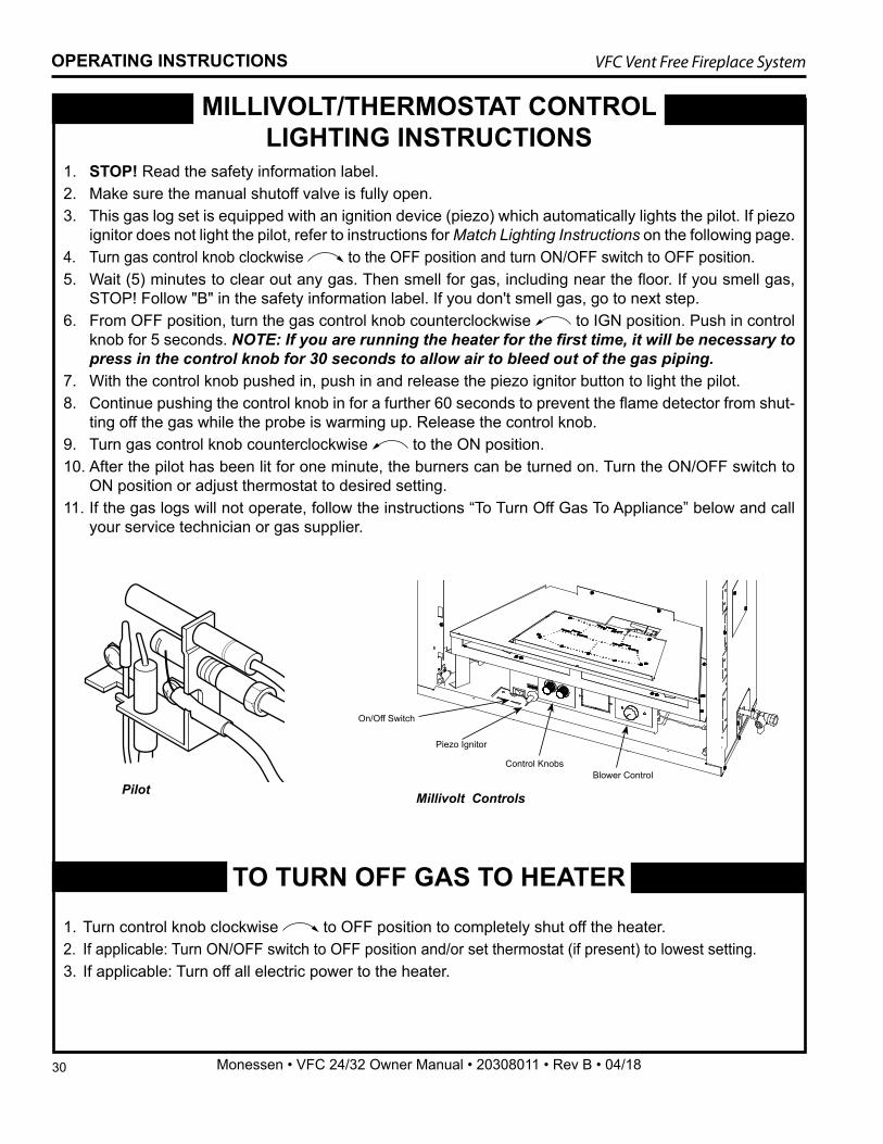
1. STOP! Read the safety information label.2. Make sure the manual shutoff valve is fully open.3. This gas log set is equipped with an ignition device (piezo) which automatically lights the pilot. If piezo
ignitor does not light the pilot, refer to instructions for Match Lighting Instructions on the following page.4. Turn gas control knob clockwise to the OFF position and turn ON/OFF switch to OFF position.5. Wait (5) minutes to clear out any gas. Then smell for gas, including near the floor. If you smell gas,
STOP! Follow "B" in the safety information label. If you don't smell gas, go to next step.6. From OFF position, turn the gas control knob counterclockwise to IGN position. Push in control
knob for 5 seconds. NOTE: If you are running the heater for the first time, it will be necessary to press in the control knob for 30 seconds to allow air to bleed out of the gas piping.
7. With the control knob pushed in, push in and release the piezo ignitor button to light the pilot.8. Continue pushing the control knob in for a further 60 seconds to prevent the flame detector from shut-
ting off the gas while the probe is warming up. Release the control knob.9. Turn gas control knob counterclockwise to the ON position.10. After the pilot has been lit for one minute, the burners can be turned on. Turn the ON/OFF switch to
ON position or adjust thermostat to desired setting.11. If the gas logs will not operate, follow the instructions “To Turn Off Gas To Appliance” below and call
your service technician or gas supplier.
Pilot
1. Turn control knob clockwise to OFF position to completely shut off the heater.2. If applicable: Turn ON/OFF switch to OFF position and/or set thermostat (if present) to lowest setting.3. If applicable: Turn off all electric power to the heater.
MILLIVOLT/THERMOSTAT CONTROL LIGHTING INSTRUCTIONS
TO TURN OFF GAS TO HEATER
OPERATING INSTRUCTIONS
Millivolt Controls
Piezo Ignitor
Control Knobs
On/Off Switch
Blower Control
31
VFC Vent Free Fireplace System
Monessen • VFC 24/32 Owner Manual • 20308011 • Rev B • 04/18
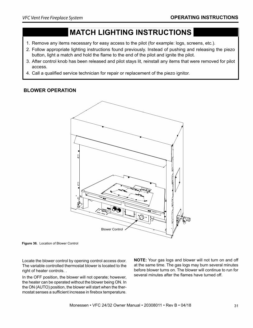
Locate the blower control by opening control access door. The variable controlled thermostat blower is located to the right of heater controls. .In the OFF position, the blower will not operate; however, the heater can be operated without the blower being ON. In the ON (AUTO) position, the blower will start when the ther-mostat senses a sufficient increase in firebox temperature.
BLOWER OPERATION
OPERATING INSTRUCTIONS
MATCH LIGHTING INSTRUCTIONS 1. Remove any items necessary for easy access to the pilot (for example: logs, screens, etc.).2. Follow appropriate lighting instructions found previously. Instead of pushing and releasing the piezo
button, light a match and hold the flame to the end of the pilot and ignite the pilot.3. After control knob has been released and pilot stays lit, reinstall any items that were removed for pilot
access.4. Call a qualified service technician for repair or replacement of the piezo ignitor.
Figure 36. Location of Blower Control
NOTE: Your gas logs and blower will not turn on and off at the same time. The gas logs may burn several minutes before blower turns on. The blower will continue to run for several minutes after the flames have turned off.
Blower Control
32
VFC Vent Free Fireplace System
Monessen • VFC 24/32 Owner Manual • 20308011 • Rev B • 04/18
ANNUAL CLEANING/INSPECTIONRefer to parts diagram for location of items discussed below.Annual inspection and cleaning by your dealer or qualified service technician is recommended to prevent malfunction and/or sooting.Remove logs, handling carefully by holding gently at each end. Gloves are recommended. If skin becomes irritated, wash gently with soap and water. Refer to manual for correct log placement.
• Inspect and clean burner air intake holes. Remove lint or particles with vacuum, brush or pipe cleaners. Failure to keep air intake holes clean will result in sooting and poor combustion.
• Inspect and clean all burner ports.• Inspect ODS pilot for operation and accumulation of
lint at air intake holes.• Verify flame pattern and log placement for proper
operation.• Verify smooth and responsive ignition of main burner
and rear burner.
CLEANING AND SERVICING
PERIODIC CLEANINGRefer to parts diagram for location of items discussed below.
• Do not use cleaning fluid to clean logs or any part of heater.
• Brush logs with soft bristle brush or vacuum with brush attachment.
• Vacuum loose particles and dust from the front and rear burner, control and piezo covers and grate weldment.
• Inspect and clean burner air intake holes. Remove lint or particles with vacuum, brush, or pipe cleaners. Failure to keep air intake holes clean will result in sooting and poor combustion.
• External case should be dusted and wiped with a wet soapy cloth.
WARNING: Turn off heater and allow to cool before cleaning. Disconnect electrical power before cleaning or servicing.
33
VFC Vent Free Fireplace System
Monessen • VFC 24/32 Owner Manual • 20308011 • Rev B • 04/18
OPTIONAL ACCESSORIES
FORCED AIR KITIf you are installing the forced air kit (Models BLO24T or BLOT), see the installation instructions provided with the kit for electrical wiring requirements or the blower instal-lation section. Model VFC24 uses blower model BLO24T. Model VFC32 uses blower model BLOT.
The firebox must be connected to main power supply at time of firebox installation. The blower must be installed prior to the installation of the unvented heater. The electri-cal connections must be made before the firebox is framed and enclosed in the finished walls.
INSTALLING OPTIONAL FIREBRICK PANELSNOTE: Firebrick liner kits may be used only with the VFC vent free fireplace systems. Please verify the size and model number of your insert to be certain the kit you pur-chased is correct.
KIT CONTENTS:• One (1) Center panel • Two (2) self-drilling #8 screws• One (1) Left panel• Two (2) Brick retainer brackets• One (1) Right panel TOOLS REQUIRED:Drill with 1/4" hex head or Phillips bit
INSTRUCTIONS:1. Remove screen frame, stones, fireglass or logs (if ap-
plicable) per the VFC Installation and Operating In-structions.
2. Place rear ceramic firebrick panel against the center of the rear wall of the firebox. Place on rear log support bracket.
3. Place left and right ceramic firebrick panels against firebox sides and attach at the top with retainer bracket with supplied self drilling screws.
4. Replace fireglass, stones and/or logs as applicable and re-install screen frame.
Figure 37. Install Side Firebrick Panel
KT1434install firebrick
Retainer Brackets
KT1435installed
Figure 38. Install Back Firebrick Panel

34
VFC Vent Free Fireplace System
Monessen • VFC 24/32 Owner Manual • 20308011 • Rev B • 04/18
INSTALLING OPTIONAL PORCELAIN PANELSNOTE: Porcelain liner kits are approved for use with op-tional fireglass and log kits. These kits are designed to fit VFC vent free fireplace systems. Please verify the size and model number of your fireplace to be certain the kit you purchased is correct.
KIT CONTENTS:• One (1) Right panel• One (1) Left panel• One (1) Rear panel• Four (4) Self-drilling #8 screws
INSTALLATION INSTRUCTIONS:1. Remove screen frame, stones, fireglass or logs (if ap-
plicable).2. Place rear panel against the center of the rear wall of
the firebox.3. Place left and right panels against firebox sides and at-
tach top flanges of the panels using self-drilling screws provided.
4. Replace fireglass or logs as applicable and re-install screen frame.
Figure 39. Install Porcelain Panels
INSTALLING OPTIONAL BLACK MAGIC PANELSNOTE: Black Magic glass liner kits are approved for use with optional fireglass and log kits. These kits are designed to fit VFC vent free fireplace systems. Please verify the size and model number of your fireplace to be certain the kit you purchased is correct.
KIT CONTENTS:• One (1) Center panel• One (1) Left panel• One (1) Right panel• Two (2) Glass retainer brackets• Two (2) Self drilling #8 screws
INSTALLATION INSTRUCTIONS:1. Remove screen frame, fireglass or logs (if applicable).2. NOTE: All panels will be installed with the dimples in
the glass facing the firebox. Place rear glass liner panel against the center of the
rear wall of the firebox.3. Place left and right glass liner panels against firebox
sides and attach at the top with retainer bracket using supplied screws.
4. Replace fireglass or logs as applicable and re-install screen frame.
Figure 40. Install Black Magic Glass Panels
35
VFC Vent Free Fireplace System
Monessen • VFC 24/32 Owner Manual • 20308011 • Rev B • 04/18
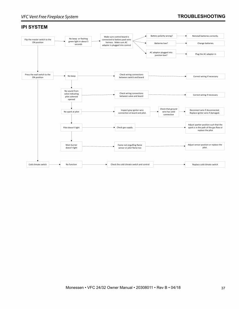
NOTE: All troubleshooting items are listed in order of operation.
TROUBLESHOOTING
WARNING: Turn appliance OFF and allow to cool before servicing. Only a qualified service person should service and repair the heater.
OBSERVED PROBLEM POSSIBLE CAUSE SOLUTIONWhen ignitor button is pressed, there is no spark at ODS/pilot.
1. Ignitor electrode positioned wrong.2. Ignitor electrode is broken.3. Ignitor electrode not connected to
ignitor cable.4. Ignitor cable pinched or wet. Keep
ignitor cable dry.5. Broken ignitor cable.6. Bad piezo ignitor.
1 Replace ignitor.2. Replace ignitor.3. Reconnect ignitor cable.
4. Free ignitor cable if pinched by any metal or tubing.
5. Replace ignitor cable.6. Replace piezo ignitor.
Appliance produces unwanted odors.
1. Appliance burning vapors from paint, hair spray, glues, etc.
2. Gas leak.3. Initial burn off.
1. Ventilate room. Stop using odor causing prod-ucts while heater is running.
2. Locate and correct all leaks.3. Ventilate room and turn unit on high until odor
is gone. Odor should be gone after 6 hours of continuous use.
Appliance shuts off during use. 1. Not enough fresh air is available for ODS/ pilot to operate.
2. Low line pressure.3. ODS/pilot is partially clogged.4. Defective Thermopile.
5. Restrictions in incoming air flow
1. Open window and/or door for ventilation.2. Contact local gas company.3. Clean ODS/pilot.4. Check pilot flame, check wire connections, check
output, should be 325 millivolts across TH/TP and TP Terminals with ON/OFF switches off.
5. Check for bottom riser on glass door, sunken fireplace, excessive lava rock/cinders densely packed against grate.
Gas odor even when control knob is in OFF position.
1. Gas leak.2. Control valve defective.
1. Locate and correct all leaks.2. Replace control valve.
When ignitor button is pressed, there is spark at ODS pilot, but no ignition.
1. Gas supply turned off or manual shutoff valve closed.
2. Control knob not in PILOT position.3. Control knob not pressed in while in
PILOT position.4. Air in gas lines when installed.
5. ODS/pilot is clogged.6. Gas regulator setting is not correct.
1. Turn on gas supply or open manual shutoff valve.
2. Turn control knob to PILOT position.3. Press in control knob while in PILOT position.
4. Continue holding down control knob. Repeat igniting operation until air is removed.
5. Replace ODS/pilot assembly or get it serviced.6. Replace gas regulator.
continued on following page
36
VFC Vent Free Fireplace System
Monessen • VFC 24/32 Owner Manual • 20308011 • Rev B • 04/18
OBSERVED PROBLEM POSSIBLE CAUSE SOLUTIONODS/pilot lights, but flame goes out when control knob is released.
1. Control knob not fully pressed in.2. Control knob not pressed in long
enough.3. Manual shutoff valve not fully open.4. Thermocouple connection loose at
control valve.5. Pilot flame not touching thermocou-
ple, which allows thermocouple to cool, causing pilot flame to go out. This problem could be caused by either low gas pressure, or a dirty or partially clogged ODS/pilot.
6. Thermocouple damaged.7. Control valve damaged.
1. Press in control knob fully.2. After ODS/pilot lights, keep control knob pressed
in for 30 seconds.3. Fully open manual shutoff valve.4. Hand tighten thermocouple connection until
snug, then tighten 1/4 turn more.5a.Contact local gas company.5b.Clean pilot with vacuum cleaner.
6. Replace thermocouple.7. Replace control valve.
Burner does not light after ODS/pilot is lit.
1. Burner orifice is clogged.2. Burner orifice diameter is too small.3. Inlet gas pressure is too low.
1. Clean orifice.2. Replace burner orifice.3. Contact qualified service person.
Burner backfires during com-bustion.
1. Manifold pressure is too low.2. Burner orifice is clogged.
1. Contact local gas company.2. Clean burner or replace burner orifice.
Slight smoke or odor during initial operation.
1. Burner orifice is clogged or dam-aged.
2. Burner is damaged.3. Gas regulator defective.
1. Clean burner or replace burner orifice.2. Replace burner.
3. Replace gas regulator.Logs appear to smoke after initial operation.
1. Vapors from paint or curing process of logs.
2. Vapors or smoke continue after heater is run with damper or window open for several hours.
1. Problem will stop after a few hours of operation. Run the heater with the damper open if you have one, or open a window for the first few hours.
2. Log heater is intended to be smokeless. Turn OFF heater and call qualified service person.
Heater produces a whistling noise when burner is lit.
1. Turning control knob to HIGH posi-tion when burner is cold.
2. Air in gas line.
3. Dirty or partially clogged burner ori-fices.
1. Turn control knob to LOW position and let warm up for a minute.
2. Operate burner until air is removed from line. Have gas line checked by local gas company.
3. Clean burner or replace burner orifice.
No gas to pilot. 1. LP-regulator shut down due to inlet pressure too high.
1. Verify LP tank regulator is installed and set at 11" to 13" w.c.
2. Replace regulator on heater.Blower does not work. 1. Power cord not plugged in.
2. Loose wire connections.3. Defective blower thermostat.
1. Plug power cord into junction box found in lower access level.
2. Check wire connections, reconnect if loose.3. Replace thermostat.
WARNING: If the gas quality is bad, your pilot may not stay lit, the burners may produce soot and the heater may backfire when lit. If the gas quality or pressure is low, contact your local gas supplier immediately.
WARNING: Failure to position the parts in accordance with these diagrams or failure to use only parts specifically approved with this appliance may result in property damage or personal injury.
TROUBLESHOOTING
37
VFC Vent Free Fireplace System
Monessen • VFC 24/32 Owner Manual • 20308011 • Rev B • 04/18
IPI SYSTEM
TROUBLESHOOTING
Flip the master switch to the ON position
No beep or flashing green light in about 5
seconds
Make sure control board is connected to battery pack wire
harness. Make sure AC adaptor is plugged into control
Battery polarity wrong? Reinstall batteries correctly.
Batteries low? Change batteries.
AC adaptor plugged into junction box? Plug the AC adaptor in
Press the wall switch to the ON position No beep Check wiring connections
between switch and board Correct wiring if necessary
No sound from valve indicating pilot solenoid
opened
Check wiring connections between valve and board Correct wiring if necessary
No spark at pilotInspect gray ignitor wire
connection at board and pilot. Reconnect wire if disconnected. Replace ignitor wire if damaged.
Pilot doesn't light Check gas supply.
Check that ground wire has solid
connection
Adjust sparker position such that the spark is in the path of the gas flow or
replace the pilot
Main burner doesn't light
Flame not engulfing flame sensor or pilot flame too
Adjust sensor position or replace the pilot.
Cold climate switch No function Check the cold climate switch and control Replace cold climate switch
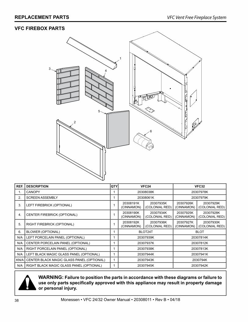
38
VFC Vent Free Fireplace System
Monessen • VFC 24/32 Owner Manual • 20308011 • Rev B • 04/18
REPLACEMENT PARTS
1
43
2
5
6
WARNING: Failure to position the parts in accordance with these diagrams or failure to use only parts specifically approved with this appliance may result in property damage or personal injury.
VFC FIREBOX PARTS
REF. DESCRIPTION QTY VFC24 VFC321. CANOPY 1 20308038K 20307978K
2. SCREEN ASSEMBLY 1 20308061K 20307979K
3. LEFT FIREBRICK (OPTIONAL) 1 20308191K (CINNAMON)
20307935K (COLONIAL RED)
20307926K (CINNAMON)
20307929K (COLONIAL RED)
4. CENTER FIREBRICK (OPTIONAL) 1 20308190K (CINNAMON)
20307934K (COLONIAL RED)
20307925K (CINNAMON)
20307928K (COLONIAL RED)
5. RIGHT FIREBRICK (OPTIONAL) 1 20308192K (CINNAMON)
20307936K (COLONIAL RED)
20307927K (CINNAMON)
20307930K (COLONIAL RED)
6. BLOWER (OPTIONAL) 1 BLOT24T BLOT
N/A LEFT PORCELAIN PANEL (OPTIONAL) 1 20307939K 20307814K
N/A CENTER PORCELAIN PANEL (OPTIONAL) 1 20307937K 20307812K
N/A RIGHT PORCELAIN PANEL (OPTIONAL) 1 20307938K 20307813K
N/A LEFT BLACK MAGIC GLASS PANEL (OPTIONAL) 1 20307944K 20307941K
KN/A CENTER BLACK MAGIC GLASS PANEL (OPTIONAL) 1 20307943K 2030794K
N/A RIGHT BLACK MAGIC GLASS PANEL (OPTIONAL) 1 20307945K 20307942K
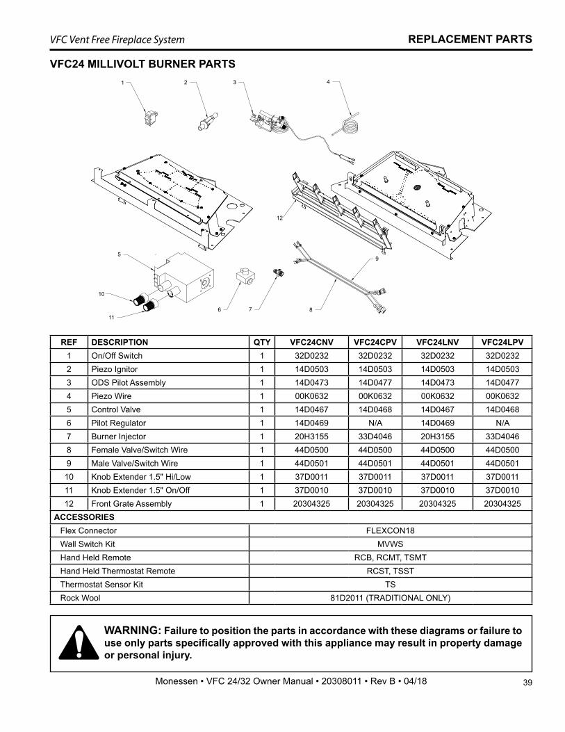
39
VFC Vent Free Fireplace System
Monessen • VFC 24/32 Owner Manual • 20308011 • Rev B • 04/18
REPLACEMENT PARTS
VFC24 MILLIVOLT BURNER PARTS
REF DESCRIPTION QTY VFC24CNV VFC24CPV VFC24LNV VFC24LPV1 On/Off Switch 1 32D0232 32D0232 32D0232 32D02322 Piezo Ignitor 1 14D0503 14D0503 14D0503 14D05033 ODS Pilot Assembly 1 14D0473 14D0477 14D0473 14D04774 Piezo Wire 1 00K0632 00K0632 00K0632 00K06325 Control Valve 1 14D0467 14D0468 14D0467 14D04686 Pilot Regulator 1 14D0469 N/A 14D0469 N/A7 Burner Injector 1 20H3155 33D4046 20H3155 33D40468 Female Valve/Switch Wire 1 44D0500 44D0500 44D0500 44D05009 Male Valve/Switch Wire 1 44D0501 44D0501 44D0501 44D0501
10 Knob Extender 1.5" Hi/Low 1 37D0011 37D0011 37D0011 37D001111 Knob Extender 1.5" On/Off 1 37D0010 37D0010 37D0010 37D001012 Front Grate Assembly 1 20304325 20304325 20304325 20304325
ACCESSORIESFlex Connector FLEXCON18Wall Switch Kit MVWSHand Held Remote RCB, RCMT, TSMTHand Held Thermostat Remote RCST, TSSTThermostat Sensor Kit TSRock Wool 81D2011 (TRADITIONAL ONLY)
WARNING: Failure to position the parts in accordance with these diagrams or failure to use only parts specifically approved with this appliance may result in property damage or personal injury.
1 2 3 4
6 7 8
9
10
11
5
12
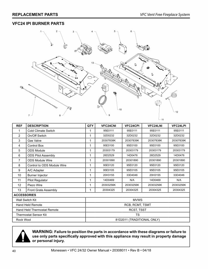
40
VFC Vent Free Fireplace System
Monessen • VFC 24/32 Owner Manual • 20308011 • Rev B • 04/18
REPLACEMENT PARTS
WARNING: Failure to position the parts in accordance with these diagrams or failure to use only parts specifically approved with this appliance may result in property damage or personal injury.
VFC24 IPI BURNER PARTS
REF DESCRIPTION QTY VFC24CNI VFC24CPI VFC24LNI VFC24LPI1 Cold Climate Switch 1 95E0111 95E0111 95E0111 95E0111
2 On/Off Switch 1 32D0232 32D0232 32D0232 32D0232
3 Gas Valve 1 20307838K 20307839K 20307838K 20307839K
4 Control Box 1 95E0100 95E0100 95E0100 95E0100
5 ODS Module 1 20303179 20303179 20303179 20303179
6 ODS Pilot Assembly 1 26D2529 14D0476 26D2529 14D0476
7 ODS Module Wire 1 20301890 20301890 20301890 20301890
8 Control to ODS Module Wire 1 95E0120 95E0120 95E0120 95E0120
9 A/C Adapter 1 95E0105 95E0105 95E0105 95E0105
10 Burner Injector 1 20H3155 33D4046 20H3155 33D4046
11 Pilot Regulator 1 14D0469 N/A 14D0469 N/A
12 Piezo Wire 1 20303256K 20303256K 20303256K 20303256K
13 Front Grate Assembly 1 20304325 20304325 20304325 20304325
ACCESSORIESWall Switch Kit MVWSHand Held Remote RCB, RCMT, TSMTHand Held Thermostat Remote RCST, TSSTThermostat Sensor Kit TSRock Wool 81D2011 (TRADITIONAL ONLY)
1 2 3 4 5 6
7 8 9
10
11
12
13

41
VFC Vent Free Fireplace System
Monessen • VFC 24/32 Owner Manual • 20308011 • Rev B • 04/18
REPLACEMENT PARTS
VFC32 MILLIVOLT BURNER PARTS
WARNING: Failure to position the parts in accordance with these diagrams or failure to use only parts specifically approved with this appliance may result in property damage or personal injury.
REF DESCRIPTION QTY VFC32CNV VFC32CPV VFC32LNV VFC32LPV1 On/Off Switch 1 32D0232 32D0232 32D0232 32D02322 Piezo Ignitor 1 14D0503 14D0503 14D0503 14D05033 ODS Pilot Assembly 1 14D0473 14D0477 14D0473 14D04774 Piezo Wire 1 00K0632 00K0632 00K0632 00K06325 Control Valve 1 14D0467 14D0468 14D0467 14D04686 Pilot Regulator 1 14D0469 N/A 14D0469 N/A7 Burner Injector 1 33D5040 58D0052 33D5040 58D00528 Female Valve/Switch Wire 1 44D0500 44D0500 44D0500 44D05009 Male Valve/Switch Wire 1 44D0501 44D0501 44D0501 44D0501
10 Knob Extender 1.5" Hi/Low 1 37D0011 37D0011 37D0011 37D001111 Knob Extender 1.5" On/Off 1 37D0010 37D0010 37D0010 37D001012 Front Grate Assembly 1 20304325 20304325 20304325 20304325
ACCESSORIESFlex Connector FLEXCON18Wall Switch Kit MVWSHand Held Remote RCB, RCMT, TSMTHand Held Thermostat Remote RCST, TSSTThermostat Sensor Kit TSRock Wool 81D2011 (TRADITIONAL ONLY)
1 2 3 4
6 7 8
9
10
11
5
12
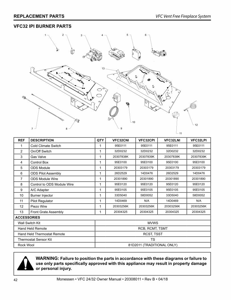
42
VFC Vent Free Fireplace System
Monessen • VFC 24/32 Owner Manual • 20308011 • Rev B • 04/18
REPLACEMENT PARTS
WARNING: Failure to position the parts in accordance with these diagrams or failure to use only parts specifically approved with this appliance may result in property damage or personal injury.
REF DESCRIPTION QTY VFC32CNI VFC32CPI VFC32LNI VFC32LPI1 Cold Climate Switch 1 95E0111 95E0111 95E0111 95E0111
2 On/Off Switch 1 32D0232 32D0232 32D0232 32D0232
3 Gas Valve 1 20307838K 20307839K 20307838K 20307839K
4 Control Box 1 95E0100 95E0100 95E0100 95E0100
5 ODS Module 1 20303179 20303179 20303179 20303179
6 ODS Pilot Assembly 1 26D2529 14D0476 26D2529 14D0476
7 ODS Module Wire 1 20301890 20301890 20301890 20301890
8 Control to ODS Module Wire 1 95E0120 95E0120 95E0120 95E0120
9 A/C Adapter 1 95E0105 95E0105 95E0105 95E0105
10 Burner Injector 1 33D5040 58D0052 33D5040 58D0052
11 Pilot Regulator 1 14D0469 N/A 14D0469 N/A
12 Piezo Wire 1 20303256K 20303256K 20303256K 20303256K
13 Front Grate Assembly 1 20304325 20304325 20304325 20304325
ACCESSORIESWall Switch Kit MVWSHand Held Remote RCB, RCMT, TSMTHand Held Thermostat Remote RCST, TSSTThermostat Sensor Kit TSRock Wool 81D2011 (TRADITIONAL ONLY)
VFC32 IPI BURNER PARTS
1 2 3 4 5 6
7 8 9
10
11
12
13
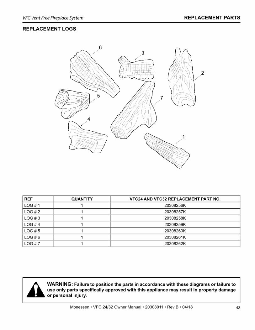
43
VFC Vent Free Fireplace System
Monessen • VFC 24/32 Owner Manual • 20308011 • Rev B • 04/18
REPLACEMENT LOGS
1
2
36
5
4
7
REF QUANTITY VFC24 AND VFC32 REPLACEMENT PART NO.LOG # 1 1 20308256KLOG # 2 1 20308257KLOG # 3 1 20308258KLOG # 4 1 20308259KLOG # 5 1 20308260KLOG # 6 1 20308261KLOG # 7 1 20308262K
REPLACEMENT PARTS
WARNING: Failure to position the parts in accordance with these diagrams or failure to use only parts specifically approved with this appliance may result in property damage or personal injury.
44
VFC Vent Free Fireplace System
Monessen • VFC 24/32 Owner Manual • 20308011 • Rev B • 04/18
LIMITED LIFETIME WARRANTY POLICYLIFETIME WARRANTYThe following components are warranted for life to the original owner, subject to proof of purchase: Firebox, Combustion Chamber, Heat Exchanger, Grate and Stainless Steel Burners.
FIVE YEAR WARRANTYThe following components are warranted for 5 years to the original owner, subject of proof of pur-chase: Refractory cement Logs, Catalytic Filter and Aluminized Burners.
BASIC WARRANTYMonessen warrants the components and materials in your gas appliance to be free from manufac-turing and material defects for a period of one year from date of installation. After installation, if any of the components manufactured by Monessen in the appliance are found to be defective in mate-rials or workmanship, Monessen will, at its option, replace or repair the defective components at no charge to the original owner. Monessen will also pay for reasonable labor costs incurred in replacing or repairing such components for a period of one year from the date of installation. Any products presented for warranty repair must be accompanied by a dated proof of purchase.
This Limited Warranty will be void if the appliance is not installed by a qualified installer in accordance with the installation instructions. The Limited Lifetime Warranty will also be void if the appliance is not operated and maintained according to the operating instructions supplied with the appliance, and does not extend to (1) firebox/burner assembly damage by accident, neglect, misuse, abuse, alteration, negligence of others, including the installation thereof by unqualified installers, (2) the costs of removal, re-installation or transportation of defective parts on the appliance, or (3) incidental or consequential damage. All service work must be performed by an authorized service representative.
This warranty is expressly in lieu of other warranties, express or implied, including the warranty of merchantability of fitness for purpose and of all other obligations or liabilities. Monessen does not assume for it any other obligations or liability in connection with the sale or use of the appliance. In states that do not allow limitations on how long an implied warranty lasts, or do not allow exclusion of indirect damages, those limitations of exclusions may not apply to you. You may also have additional rights not covered in this Limited Warranty.
Monessen reserves the right to investigate any and all claims against the Limited Warranty and de-cide upon method of settlement.
IF WARRANTY SERVICE IS NEEDED...1. Contact your supplier. Make sure you have your warranty, your sales receipt and the model/
serial number of your Monessen product.2. DO NOT ATTEMPT TO DO ANY SERVICE WORK YOURSELF.


Monessen, a brand of Hearth & Home Technologies7571 215th Street West, Lakeville, MN 50044
www.monessenhearth.com