Embed Size (px)
Citation preview
www.kozyheat.com
August 2011 SLA-42-REV-01
DIRECT VENT LINEAR FIREPLACE
INSTALLATION AND OPERATION MANUAL
Report No. 216-S-36-6.5
—Do not store or use gasoline or other flammable vapors and liquids in the vicinity of this or any other appliance. WHAT TO DO IF YOU SMELL GAS: ◙ Do not light any appliance. ◙ Do not touch any electrical switch: do not use any phone in your building. ◙ Immediately call gas supplier from a neighbors phone. Follow the gas supplier instructions. ◙ If you cannot reach your gas supplier, call the fire department. — Installation and service must be performed by a qualified installer, service agency or the gas supplier.
WARNING: If the information in these instructions is not followed exactly, a fire or explosion may result causing property damage, personal injury or loss of life.
WARNING
This appliance may be installed in an aftermarket permanently located, manufactured home (USA only) or mobile home where not prohibited by local codes. This appliance is only for use with the type of gas indicated on the rating plate. This appliance is not convertible for use with other gases, unless a certified kit is used.
HOT GLASS WILL CAUSE BURNS. DO NOT TOUCH GLASS UNTIL COOLED. NEVER ALLOW CHILDREN TO TOUCH GLASS.
INSTALLER: LEAVE THIS MANUAL WITH THE APPLIANCE.
CONSUMER: RETAIN THIS MANUAL FOR FUTURE REFERENCE .
CONGRATULATIONS! We welcome you as a new owner of a Kozy Heat gas fireplace. Kozy Heat products are designed with superior components and materials and assembled by trained craftsmen who take pride in their work. The burner and valve assembly are 100% test-fired and the complete fireplace is thoroughly inspected before packaging to ensure that you receive a quality product. Our commitment to quality and customer satisfaction have remained the same for over 30 years. We offer a complete line of gas and wood fireplaces, unique cabinets and stylish accessories to compliment any décor. Adding a fireplace is one of the best ways to increase the value of your home and we are proud to offer a network of dealers throughout the country to help make your experience everything you imagine. We pride ourselves in being dedicated to not only function and reliability, but customer safety as well. We offer our continual support and guidance to help you achieve the maximum benefit and enjoyment from your Kozy Heat gas fireplace. Jim Hussong Dudley Hussong
President Board Chairman
INTRODUCTION
Read this manual before installing or operating this appliance.
Please retain this owner‟s manual for future reference.
Homeowner Reference Information We recommend that you record the following information about your fireplace.
Model Name:______________________________ Date purchased/installed:_____________________________________
Serial Number:____________________________ Location on fireplace:________________________________________
Dealership purchased from:__________________ Dealer Phone:______________________________________________
Notes:_______________________________________________________________________________________________
____________________________________________________________________________________________________
____________________________________________________________________________________________________
PAGE 1
PAGE 2
TABLE OF CONTENTS INTRODUCTION
Introduction and Homeowner Reference Information 1
CONTENTS
Table of Contents 2
SAFETY INFORMATION
Safety Information 3
FEATURES
Features 4
COMMONWEALTH OF MASSACHUSETTS INFORMATION
Commonwealth of Massachusetts Information 5
SPECIFICATIONS
Fireplace Dimensions 6
Clearances 6
Components List 7
Additional Components Required 7
Installation Overview 7
Placement Clearance Requirements 8
Television Positioning Considerations 8
FIREPLACE PREPARATION
Stand-off / Stand-off Heat Shield Assembly & Installation 9
Nailing Flange Assembly & Installation 10
FRAMING
Wall Enclosure Rough Opening 11
Minimum Finished Opening Dimensions 11-12
Vertical Terminations 12
Horizontal Terminations 12
Facing and Finishing 13
TYPICAL INSTALLATION OPTIONS
Typical Installation Options 14
MANTEL REQUIREMENTS
Mantel Requirements 14
GLASS FRAME / CONTEMPORARY FRAME
Glass Frame Assembly Removal / Installation 15
OPTIONAL FAN KIT INSTALLATION
Optional Fan Kit Installation 16
GAS LINE CONNECTION
Gas Line Connection 17
VENTING
Approved Venting 18
Horizontal Vent System Clearances 18
Horizontal Termination Minimum / Maximum 18
#800-WPT Wall Pass-Thru Installation Instructions 19
Horizontal Min. / Max. Venting Illustrations 20
Horizontal Vent Heat Shield Installation Instructions 20
Vertical Vent System Clearances 21
Vertical Min. / Max. Venting Illustrations 21
Restrictor 21
VENTING (cont.)
Elbows 22
Horizontal & Vertical Combination Venting Illustrations 22
#800 Series Flex Vent Installation Instructions 23-24
Termination Vent Cap Location 25
Vent Termination Clearances 26
LIGHT KIT
Light Kit 27
GLASS MEDIA INSTALLATION
Glass Media Installation 27
CONTROL BOARD
Control Board Removal 28
Control Board Installation 28
OPERATING INSTRUCTIONS
Wiring Schematics 29
Valve and Pilot Assembly Components 30
Control Module Components 31
Remote Control Components 32
IPI Information 33
Remote Control Operation 34-36
Lighting and Shutdown Instructions 37-38
Pressure Testing 39
Error Codes 40
FINALIZING THE INSTALLATION
Burner Tube Adjustment / Troubleshooting 41
Restrictor Troubleshooting / Installation after Termination Completion 42
MAINTENANCE
Maintenance 43
TROUBLESHOOTING
Troubleshooting 44-45
CONVERSION KIT INSTRUCTIONS
Nat and LP Conversion Instructions 46-47
OPTIONAL #970 HEAT DUCT KIT INSTALLATION
Optional #970 Heat Duct Kit Installation 48-51
REPLACEMENT PARTS LIST
Replacement Parts List 52
WARRANTY
Warranty 53-54
SAFETY INFORMATION
PAGE 3
Installation and repair should be done only by a qualified service person. The appliance should be inspected by a
qualified service person before use. Annual inspection by a qualified service person is required to maintain warranty.
More frequent cleaning may be required due to excessive lint from carpeting, bedding materials, etc. It is imperative
that control compartments, burners and circulation air passageways of the appliance be kept clean.
If this appliance is installed directly on carpeting, tile or other combustible material other than wood flooring, the
appliance shall be installed on a metal or wood panel extending the full width and depth of the appliance.
Children and adults should be alerted to the hazards of high surface temperatures and should stay away to avoid burns
or clothing ignition.
Young children should be carefully supervised when they are in the same room as the appliance. Toddlers, young
children and others may be susceptible to accidental contact burns. A physical barrier is recommended if there are at
risk individuals in the house. To restrict access to a fireplace or stove, install an adjustable safety gate to keep toddlers,
young children and other at risk individuals out of the room and away from hot surfaces.
Clothing or other flammable material should not be placed on or near the appliance.
Adequate accessibility clearances for servicing and proper operation must be maintained.
This appliance must not share or be connected to a chimney flue serving any other appliance.
Keep area around the appliance clear of combustible materials, gasoline and other flammable vapor and liquids.
The flow of combustion and ventilation air must not be obstructed.
Due to high temperatures the appliance should be located out of traffic and away from furniture and draperies.
The glass front or any part removed for servicing the appliance must be replaced prior to operating the appliance.
Work should be done by a qualified service technician.
Clean glass only when cool and only with non-abrasive cleansers.
WARNING: DO NOT OPERATE APPLIANCE WITH THE GLASS/FRAME ASSEMBLY REMOVED, CRACKED
OR BROKEN. REPLACEMENT OF THE GLASS SHOULD ONLY BE PERFORMED BY A LICENSED OR
QUALIFIED SERVICE PERSON.
The glass assembly, Part #SL42-057T, shall only be replaced as a complete unit, as supplied by Hussong Mfg. Co., Inc.
DO NOT SUBSTITUTE MATERIALS.
Do not strike or slam glass assembly.
Any safety screen or guard removed for servicing the appliance must be replaced prior to operating the appliance.
Under no circumstances should any solid fuel (wood, coal, paper or cardboard etc.) be used in this appliance.
Keep burner and control compartment clean.
Do not use this fireplace if any part has been under water. Immediately call a qualified service technician to inspect this
appliance and to replace any part of the control system and any gas control which has been under water.
This fireplace has been tested to and complies with ANSI Z21.88-2009 / CSA 2.33-2009 “VENTED GAS FIREPLACE HEATERS” and
Testing Method for Measuring Annual Effiency, CSA P.4.1-09 / CGA 2.17-M91 (R2009) by OMNI-Test Laboratories, Portland, OR. This
installation must conform with local codes, or in the absence of local codes, with the National Fuel Gas Code, ANSI Z223.1/NFPA 54, or the Natural
Gas and Propane Installation Codes, CSA B149.1
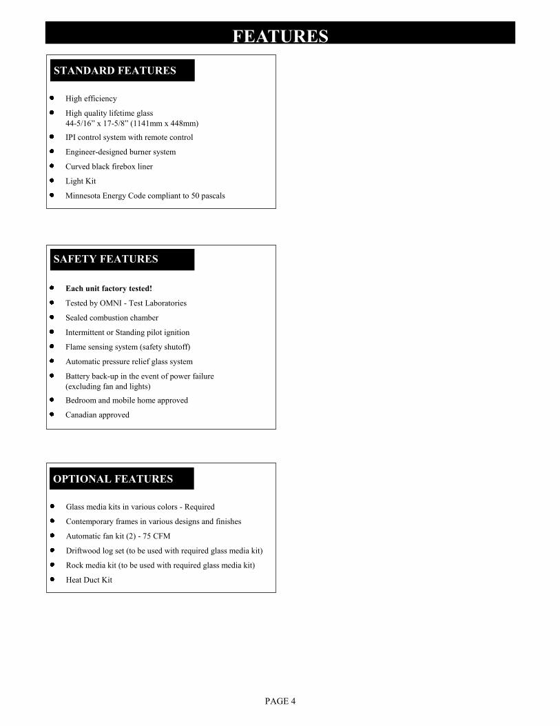
High efficiency
High quality lifetime glass
44-5/16” x 17-5/8” (1141mm x 448mm)
IPI control system with remote control
Engineer-designed burner system
Curved black firebox liner
Light Kit
Minnesota Energy Code compliant to 50 pascals
Glass media kits in various colors - Required
Contemporary frames in various designs and finishes
Automatic fan kit (2) - 75 CFM
Driftwood log set (to be used with required glass media kit)
Rock media kit (to be used with required glass media kit)
Heat Duct Kit
FEATURES
STANDARD FEATURES
OPTIONAL FEATURES
SAFETY FEATURES
PAGE 4
Each unit factory tested!
Tested by OMNI - Test Laboratories
Sealed combustion chamber
Intermittent or Standing pilot ignition
Flame sensing system (safety shutoff)
Automatic pressure relief glass system
Battery back-up in the event of power failure
(excluding fan and lights)
Bedroom and mobile home approved
Canadian approved
PAGE 5
COMMONWEALTH OF MASSACHUSETTS REQUIREMENTS
For all sidewall horizontally vented gas fueled equipment installed in every dwelling, building or structure used in whole or in part for residential purposes, including those owned or operated by the Commonwealth and where the side wall exhaust vent termination is less than (7) feet above finished grade in the
area of the venting, including but not limited to decks and porches, the following requirements shall be satisfied:
INSTALLATION OF CARBON MONOXIDE DETECTORS
At time of installation of side wall horizontally vented gas fueled equipment, the installing plumber or gas-fitter shall observe that a hard wired carbon monoxide detector with an alarm and battery back-up is installed on the floor level where the gas equipment is to be installed. In addition, the installing
plumber or gas-fitter shall observe that a battery operated or hard wired carbon monoxide detector is installed on each additional level of the dwelling,
building or structure served by the side wall horizontal vented gas fueled equipment. It shall be the responsibility of the property owner to secure the services of qualified licensed professionals for the installation of hard wired carbon monoxide detectors.
In the event that the side wall horizontally vented gas fueled equipment is installed in a crawl space or attic, the hard wired carbon monoxide detector with alarm and battery back-up may be installed on the next adjacent floor level.
In the event that the requirements of this subdivision can not be met at the time of completion of installation, the owner shall have a period of thirty (30) days
to comply with the above requirements; provided, however, that during said thirty (30) day period, a battery operated carbon monoxide detector with an
alarm shall be installed.
APPROVED CARBON MONOXIDE DETECTORS
Each carbon monoxide detector as required in accordance with the above provisions shall comply with NFPA 720 and be ANSI/UL 2034 listed and IAS certified.
SIGNAGE
A metal or plastic identification plate shall be permanently mounted to the exterior of the building at a minimum of eight (8) feet above grade directly in line with the exhaust vent terminal for the horizontally vented gas fueled heating appliance or equipment. The sign shall read, in print no less the one-half inch
(1/2) in size, “GAS VENT DIRECTLY BELOW. KEEP CLEAR OF ALL OBSTRUCTIONS”.
INSPECTION
The state or local gas inspector of the side wall horizontally vented gas fueled equipment shall not approve the installation unless, upon inspection, the inspector observes carbon monoxide detectors and signage installed in accordance with the provisions of 248 CMR 5.08 (2) (a) 1 through 4.
EXEMPTIONS
The following equipment is exempt from 248 CMR 5.08 (2) (a) 1 through 4:The equipment listed in Chapter 10 entitled “Equipment Not Required To Be Vented” in the most current edition of NFPA 54 as adopted by the Board; and Product Approved side wall horizontally vented gas fueled equipment installed
in a room or structure separate from the dwelling, building or structure used in whole or in part for residential purposes.
MANUFACTURER REQUIREMENTS - GAS EQUIPMENT VENTING SYSTEM PROVIDED
When the manufacturer of Product Approved side wall horizontally vented gas equipment provides a venting system design or venting system components with the equipment, the instructions provided by the manufacturer for installation of the equipment and the venting system shall include:
Detailed instructions for the installation of the venting system design or the venting system components; and
A complete parts list for the venting system design or venting system.
MANUFACTURER REQUIREMENTS - GAS EQUIPMENT VENTING SYSTEM NOT PROVIDED
When the manufacturer of Product Approved side wall horizontally vented gas equipment does not provide the parts for venting the flue gases, but identifies “special venting systems”, the following requirements shall be satisfied by the manufacturer:
The referenced “special venting systems” instructions shall be included with the appliance or equipment installation instructions and;
The “special venting systems” shall be Product Approved by the Board, and the instructions for that system shall include a parts list and detailed
installation instructions.
A copy of all installation instructions for all Product Approved side wall horizontally vented gas fueled equipment, all venting instructions, all parts lists for
venting instructions, and/or all venting design instructions shall remain with the appliance or equipment at the completion of the installation.
NOTE The following requirements reference various Massachusetts and national codes not contained in this manual.
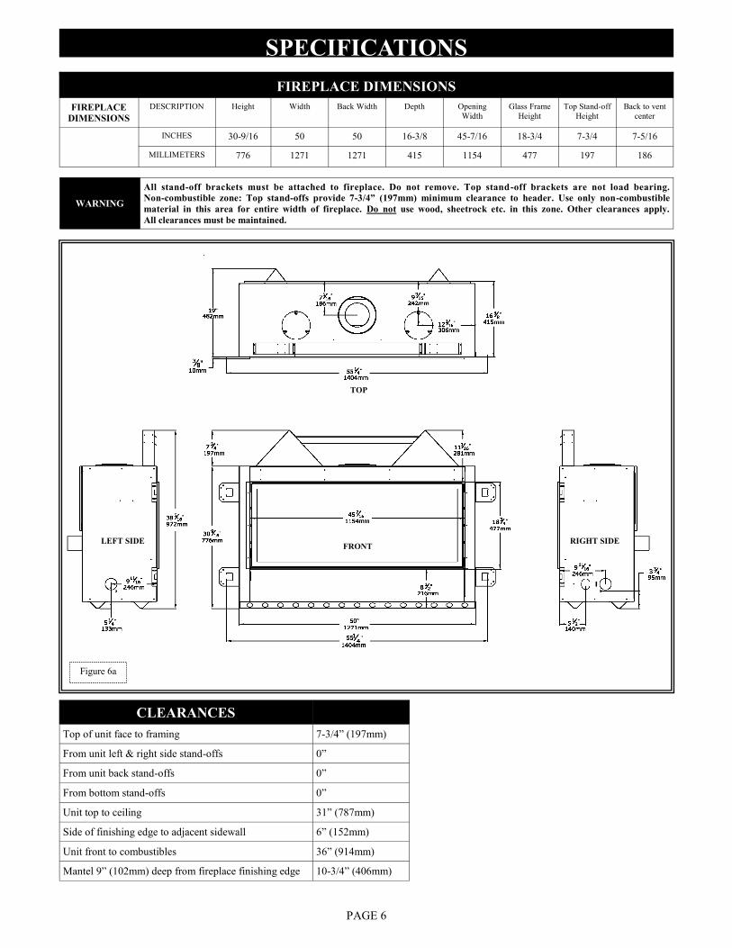
FIREPLACE DIMENSIONS
FIREPLACE
DIMENSIONS
DESCRIPTION Height Width Back Width Depth Opening
Width
Glass Frame
Height
Top Stand-off
Height
Back to vent
center
INCHES 30-9/16 50 50 16-3/8 45-7/16 18-3/4 7-3/4 7-5/16
MILLIMETERS 776 1271 1271 415 1154 477 197 186
SPECIFICATIONS
PAGE 6
CLEARANCES
Top of unit face to framing 7-3/4” (197mm)
From unit left & right side stand-offs 0”
From unit back stand-offs 0”
From bottom stand-offs 0”
Unit top to ceiling 31” (787mm)
Side of finishing edge to adjacent sidewall 6” (152mm)
Unit front to combustibles 36” (914mm)
Mantel 9” (102mm) deep from fireplace finishing edge 10-3/4” (406mm)
Figure 6a
WARNING
All stand-off brackets must be attached to fireplace. Do not remove. Top stand-off brackets are not load bearing.
Non-combustible zone: Top stand-offs provide 7-3/4” (197mm) minimum clearance to header. Use only non-combustible
material in this area for entire width of fireplace. Do not use wood, sheetrock etc. in this zone. Other clearances apply.
All clearances must be maintained.
LEFT SIDE RIGHT SIDE FRONT
TOP
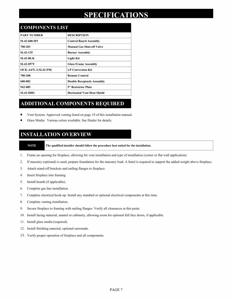
1. Frame an opening for fireplace, allowing for vent installation and type of installation (corner or flat wall application).
2. If masonry (optional) is used, prepare foundation for the masonry load. A lintel is required to support the added weight above fireplace.
3. Attach stand-off brackets and nailing flanges to fireplace.
4. Insert fireplace into framing.
5. Install hearth (if applicable).
6. Complete gas line installation.
7. Complete electrical hook-up. Install any standard or optional electrical components at this time.
8. Complete venting installation.
9. Secure fireplace to framing with nailing flanges. Verify all clearances at this point.
10. Install facing material, mantel or cabinetry, allowing room for optional full face doors, if applicable.
11. Install glass media (required).
12. Install finishing material, optional surrounds.
13. Verify proper operation of fireplace and all components.
SPECIFICATIONS
INSTALLATION OVERVIEW
COMPONENTS LIST
PAGE 7
PART NUMBER DESCRIPTION
SL42-600-IPI Control Board Assembly
700-203 Manual Gas Shut-off Valve
SL42-135 Burner Assembly
SL42-BLK Light Kit
SL42-057T Glass Frame Assembly
OCK-A47L-I-SL42-PSE LP Conversion Kit
700-208 Remote Control
600-002 Double Receptacle Assembly
942-085 5” Restrictor Plate
SL42-HHS Horizontal Vent Heat Shield
ADDITIONAL COMPONENTS REQUIRED
Vent System: Approved venting listed on page 18 of this installation manual.
Glass Media: Various colors available. See Dealer for details.
NOTE The qualified installer should follow the procedure best suited for the installation.
Mounting a TV above a fireplace has become common practice. With this in mind, we advise you to read the following paragraphs
carefully before considering installing a television above your fireplace.
Most TV manufacturers specify in their instructions that a TV should not be installed on, near, or above a heat source. Television location
rests solely on the homeowner and Hussong Manufacturing will not be held liable for any adverse affects on a TV located near a Kozy Heat
Fireplace that may be caused by heat.
TV operating temperature is also affected by wall and mantle construction material. It is the customers responsibility to satisfy themselves
that their TV mounting and mantle design will not exceed the listed maximum operating temperature of their electronic goods.
TELEVISION POSITIONING CONSIDERATIONS
PLACEMENT CLEARANCE REQUIREMENTS
This fireplace must be installed on a level surface capable of supporting fireplace and venting.
Fireplace must be placed directly on wood or non-combustible surface (not linoleum or carpet) extending entire depth and width of
fireplace.
Due to high surface temperatures, fireplace should be located out of traffic and away from furniture and draperies.
This fireplace may be installed in a bedroom.
Please be aware of the large amount of heat this fireplace will produce when determining a location.
SPECIFICATIONS
PAGE 8
FIREPLACE PREPARATION
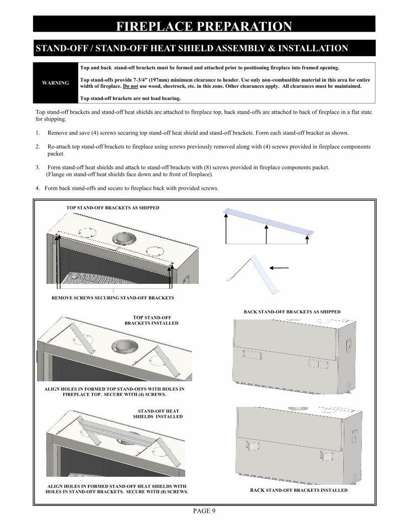
Top stand-off brackets and stand-off heat shields are attached to fireplace top, back stand-offs are attached to back of fireplace in a flat state
for shipping.
1. Remove and save (4) screws securing top stand-off heat shield and stand-off brackets. Form each stand-off bracket as shown.
2. Re-attach top stand-off brackets to fireplace using screws previously removed along with (4) screws provided in fireplace components
packet.
3. Form stand-off heat shields and attach to stand-off brackets with (8) screws provided in fireplace components packet.
(Flange on stand-off heat shields face down and to front of fireplace).
4. Form back stand-offs and secure to fireplace back with provided screws.
STAND-OFF / STAND-OFF HEAT SHIELD ASSEMBLY & INSTALLATION
PAGE 9
TOP STAND-OFF BRACKETS AS SHIPPED
REMOVE SCREWS SECURING STAND-OFF BRACKETS
ALIGN HOLES IN FORMED TOP STAND-OFFS WITH HOLES IN
FIREPLACE TOP. SECURE WITH (4) SCREWS.
TOP STAND-OFF
BRACKETS INSTALLED
ALIGN HOLES IN FORMED STAND-OFF HEAT SHIELDS WITH
HOLES IN STAND-OFF BRACKETS. SECURE WITH (8) SCREWS.
STAND-OFF HEAT
SHIELDS INSTALLED
WARNING
Top and back stand-off brackets must be formed and attached prior to positioning fireplace into framed opening.
Top stand-offs provide 7-3/4” (197mm) minimum clearance to header. Use only non-combustible material in this area for entire
width of fireplace. Do not use wood, sheetrock, etc. in this zone. Other clearances apply. All clearances must be maintained.
Top stand-off brackets are not load bearing.
BACK STAND-OFF BRACKETS AS SHIPPED
BACK STAND-OFF BRACKETS INSTALLED
FIREPLACE PREPARATION
PAGE 10
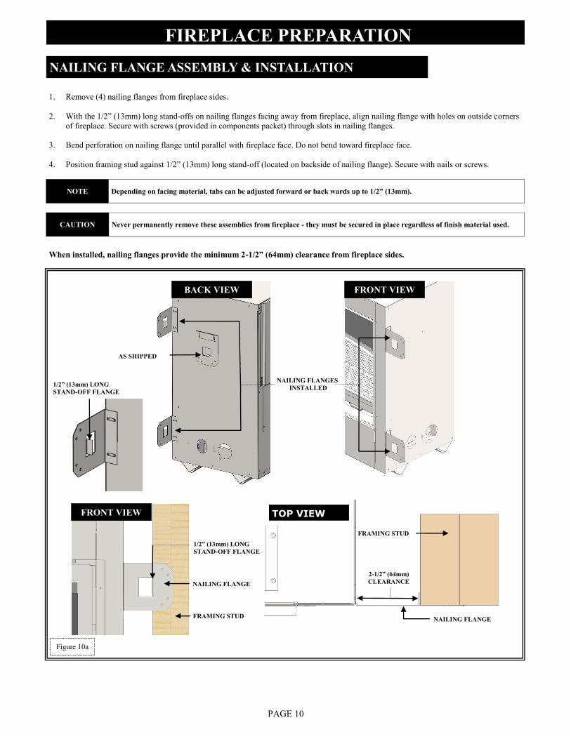
When installed, nailing flanges provide the minimum 2-1/2” (64mm) clearance from fireplace sides.
NAILING FLANGE ASSEMBLY & INSTALLATION
1. Remove (4) nailing flanges from fireplace sides.
2. With the 1/2” (13mm) long stand-offs on nailing flanges facing away from fireplace, align nailing flange with holes on outside corners
of fireplace. Secure with screws (provided in components packet) through slots in nailing flanges.
3. Bend perforation on nailing flange until parallel with fireplace face. Do not bend toward fireplace face.
4. Position framing stud against 1/2” (13mm) long stand-off (located on backside of nailing flange). Secure with nails or screws.
FRAMING STUD
NAILING FLANGE
FRAMING STUD
2-1/2” (64mm)
CLEARANCE
FRONT VIEW
AS SHIPPED
NAILING FLANGES
INSTALLED
NAILING FLANGE
1/2” (13mm) LONG
STAND-OFF FLANGE
TOP VIEW
Figure 10a
NOTE Depending on facing material, tabs can be adjusted forward or back wards up to 1/2” (13mm).
CAUTION Never permanently remove these assemblies from fireplace - they must be secured in place regardless of finish material used.
BACK VIEW FRONT VIEW
1/2” (13mm) LONG
STAND-OFF FLANGE
FRAMING
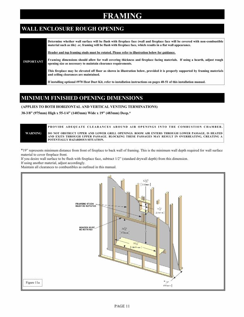
(APPLIES TO BOTH HORIZONTAL AND VERTICAL VENTING TERMINATIONS) 38-3/8” (975mm) High x 55-1/4” (1403mm) Wide x 19” (483mm) Deep.*
MINIMUM FINISHED OPENING DIMENSIONS
WALL ENCLOSURE ROUGH OPENING
PAGE 11
Figure 11a
IMPORTANT
Determine whether wall surface will be flush with fireplace face (wall and fireplace face will be covered with non-combustible
material such as tile) or, framing will be flush with fireplace face, which results in a flat wall appearance.
Header and top framing studs must be rotated. Please refer to illustration below for guidance.
Framing dimensions should allow for wall covering thickness and fireplace facing materials. If using a hearth, adjust rough
opening size as necessary to maintain clearance requirements.
This fireplace may be elevated off floor as shown in illustration below, provided it is properly supported by framing materials
and ceiling clearances are maintained.
If installing optional #970 Heat Duct Kit, refer to installation instructions on pages 48-51 of this installation manual.
WARNING
P R O V I D E A D E Q U A T E C L E A R A N C E S A R O U N D A I R O P E N I N G S I N T O T H E C O M B U S T I O N C H A M B E R .
DO NOT OBSTRUCT UPPER AND LOWER GRILL OPENINGS. ROOM AIR ENTERS THROUGH LOWER PASSAGE, IS HEATED
AND EXITS THROUGH UPPER PASSAGE. BLOCKING THESE PASSAGES MAY RESULT IN OVERHEATING, CREATING A
POTENTIALLY HAZARDOUS SITUATION.
*19” represents minimum distance from front of fireplace to back wall of framing. This is the minimum wall depth required for wall surface
material to cover fireplace front.
If you desire wall surface to be flush with fireplace face, subtract 1/2” (standard drywall depth) from this dimension.
If using another material, adjust accordingly.
Maintain all clearances to combustibles as outlined in this manual.
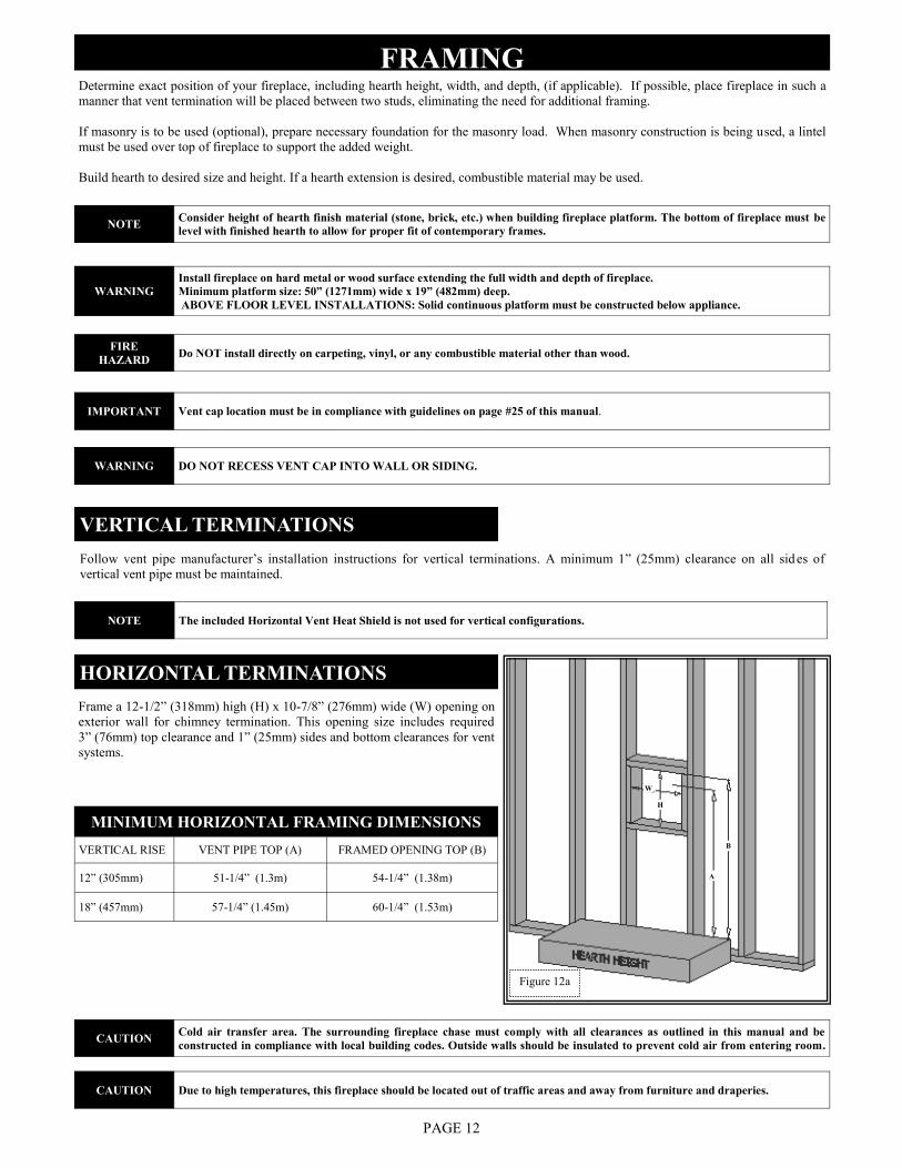
Frame a 12-1/2” (318mm) high (H) x 10-7/8” (276mm) wide (W) opening on
exterior wall for chimney termination. This opening size includes required
3” (76mm) top clearance and 1” (25mm) sides and bottom clearances for vent
systems.
HORIZONTAL TERMINATIONS
Follow vent pipe manufacturer‟s installation instructions for vertical terminations. A minimum 1” (25mm) clearance on all sid es of
vertical vent pipe must be maintained.
VERTICAL TERMINATIONS
MINIMUM HORIZONTAL FRAMING DIMENSIONS
VERTICAL RISE VENT PIPE TOP (A) FRAMED OPENING TOP (B)
12” (305mm) 51-1/4” (1.3m) 54-1/4” (1.38m)
18” (457mm) 57-1/4” (1.45m) 60-1/4” (1.53m)
FRAMING Determine exact position of your fireplace, including hearth height, width, and depth, (if applicable). If possible, place fireplace in such a
manner that vent termination will be placed between two studs, eliminating the need for additional framing.
If masonry is to be used (optional), prepare necessary foundation for the masonry load. When masonry construction is being used, a lintel
must be used over top of fireplace to support the added weight.
Build hearth to desired size and height. If a hearth extension is desired, combustible material may be used.
PAGE 12
Figure 12a
CAUTION Cold air transfer area. The surrounding fireplace chase must comply with all clearances as outlined in this manual and be
constructed in compliance with local building codes. Outside walls should be insulated to prevent cold air from entering room.
CAUTION Due to high temperatures, this fireplace should be located out of traffic areas and away from furniture and draperies.
WARNING DO NOT RECESS VENT CAP INTO WALL OR SIDING.
WARNING Install fireplace on hard metal or wood surface extending the full width and depth of fireplace.
Minimum platform size: 50” (1271mm) wide x 19” (482mm) deep.
ABOVE FLOOR LEVEL INSTALLATIONS: Solid continuous platform must be constructed below appliance.
IMPORTANT Vent cap location must be in compliance with guidelines on page #25 of this manual.
NOTE Consider height of hearth finish material (stone, brick, etc.) when building fireplace platform. The bottom of fireplace must be
level with finished hearth to allow for proper fit of contemporary frames.
NOTE The included Horizontal Vent Heat Shield is not used for vertical configurations.
FIRE
HAZARD Do NOT install directly on carpeting, vinyl, or any combustible material other than wood.
W
H
B
A
PAGE 13
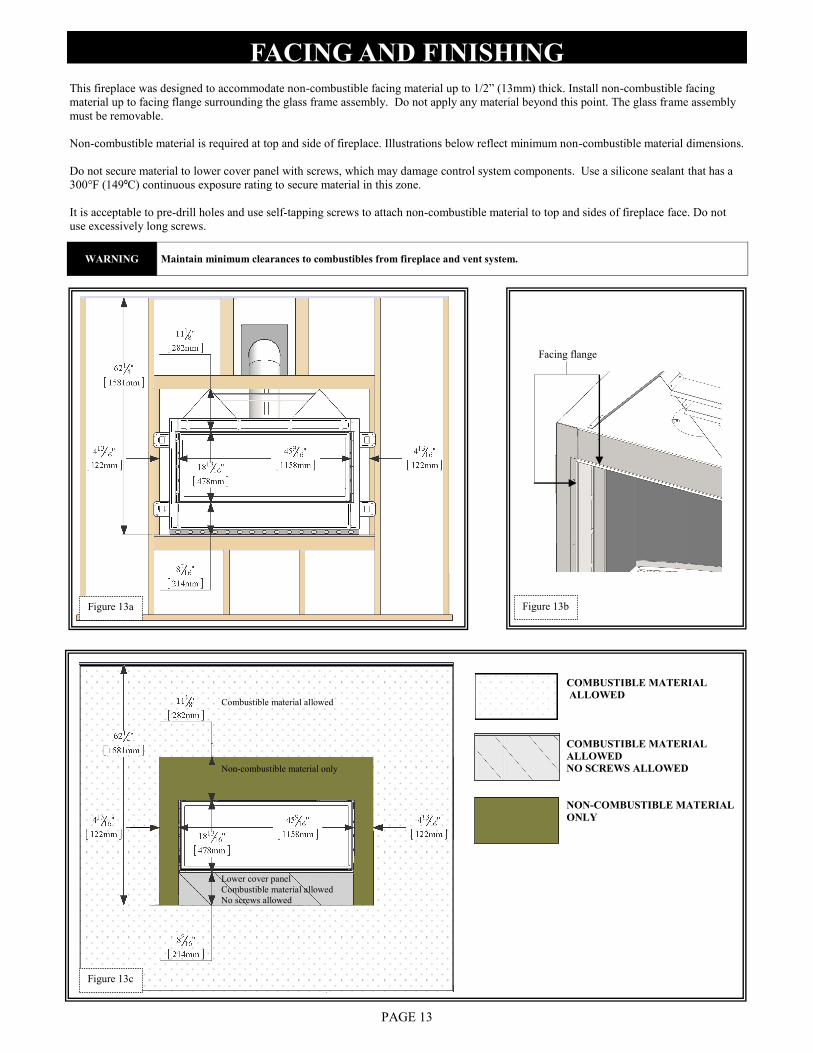
FACING AND FINISHING This fireplace was designed to accommodate non-combustible facing material up to 1/2” (13mm) thick. Install non-combustible facing
material up to facing flange surrounding the glass frame assembly. Do not apply any material beyond this point. The glass frame assembly
must be removable.
Non-combustible material is required at top and side of fireplace. Illustrations below reflect minimum non-combustible material dimensions.
Do not secure material to lower cover panel with screws, which may damage control system components. Use a silicone sealant that has a
300°F (149ºC) continuous exposure rating to secure material in this zone.
It is acceptable to pre-drill holes and use self-tapping screws to attach non-combustible material to top and sides of fireplace face. Do not
use excessively long screws.
WARNING Maintain minimum clearances to combustibles from fireplace and vent system.
COMBUSTIBLE MATERIAL
ALLOWED
COMBUSTIBLE MATERIAL
ALLOWED
NO SCREWS ALLOWED
NON-COMBUSTIBLE MATERIAL
ONLY
Lower cover panel
Combustible material allowed
No screws allowed
Facing flange
Combustible material allowed
Non-combustible material only
Figure 13a
Figure 13c
Figure 13b
PAGE 14
MANTEL REQUIREMENTS
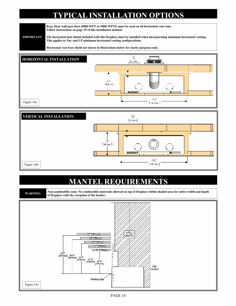
TYPICAL INSTALLATION OPTIONS
HORIZONTAL INSTALLATION
Figure 14b
Figure 14c
Figure 14a
IMPORTANT
Kozy Heat wall pass-thru (#800-WPT or #800-WPT2) must be used on all horizontal vent runs.
Follow instructions on page 19 of this installation manual.
The horizontal heat shield included with this fireplace must be installed when incorporating minimum horizontal venting.
This applies to Nat. and LP minimum horizontal venting configurations.
Horizontal vent heat shield not shown in illustrations below for clarity purposes only.
WARNING Non-combustible zone: No combustible materials allowed on top of fireplace within shaded area for entire width and depth
of fireplace with the exception of the header.
VERTICAL INSTALLATION
GLASS FRAME
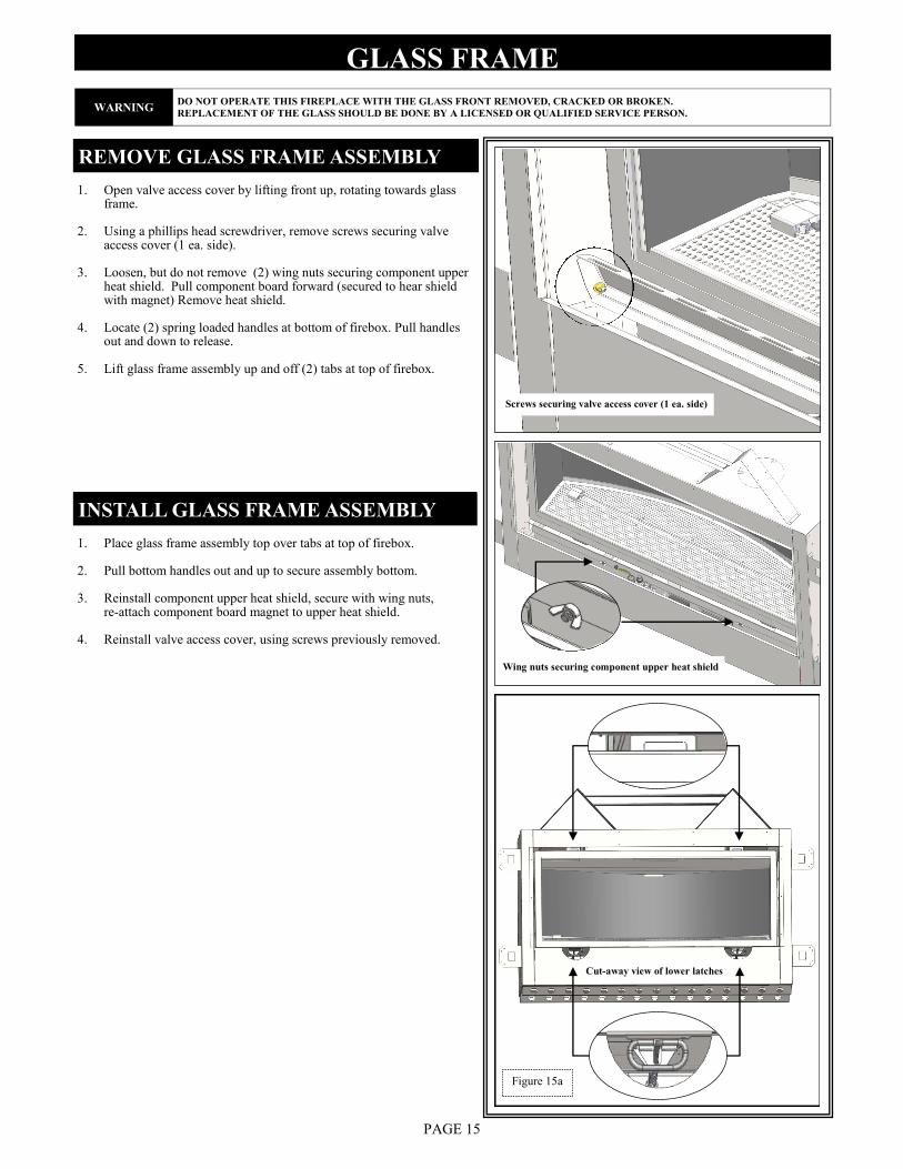
1. Place glass frame assembly top over tabs at top of firebox.
2. Pull bottom handles out and up to secure assembly bottom.
3. Reinstall component upper heat shield, secure with wing nuts, re-attach component board magnet to upper heat shield.
4. Reinstall valve access cover, using screws previously removed.
REMOVE GLASS FRAME ASSEMBLY
1. Open valve access cover by lifting front up, rotating towards glass frame.
2. Using a phillips head screwdriver, remove screws securing valve access cover (1 ea. side).
3. Loosen, but do not remove (2) wing nuts securing component upper heat shield. Pull component board forward (secured to hear shield with magnet) Remove heat shield.
4. Locate (2) spring loaded handles at bottom of firebox. Pull handles out and down to release.
5. Lift glass frame assembly up and off (2) tabs at top of firebox.
INSTALL GLASS FRAME ASSEMBLY
PAGE 15
Figure 15a
WARNING DO NOT OPERATE THIS FIREPLACE WITH THE GLASS FRONT REMOVED, CRACKED OR BROKEN.
REPLACEMENT OF THE GLASS SHOULD BE DONE BY A LICENSED OR QUALIFIED SERVICE PERSON.
Screws securing valve access cover (1 ea. side)
Wing nuts securing component upper heat shield
Cut-away view of lower latches
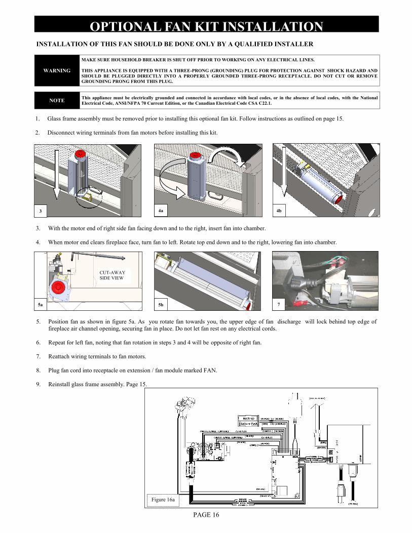
5. Position fan as shown in figure 5a. As you rotate fan towards you, the upper edge of fan discharge will lock behind top edge of
fireplace air channel opening, securing fan in place. Do not let fan rest on any electrical cords.
6. Repeat for left fan, noting that fan rotation in steps 3 and 4 will be opposite of right fan.
7. Reattach wiring terminals to fan motors.
8. Plug fan cord into receptacle on extension / fan module marked FAN.
9. Reinstall glass frame assembly. Page 15.
OPTIONAL FAN KIT INSTALLATION
INSTALLATION OF THIS FAN SHOULD BE DONE ONLY BY A QUALIFIED INSTALLER
WARNING
MAKE SURE HOUSEHOLD BREAKER IS SHUT OFF PRIOR TO WORKING ON ANY ELECTRICAL LINES.
THIS APPLIANCE IS EQUIPPED WITH A THREE-PRONG (GROUNDING) PLUG FOR PROTECTION AGAINST SHOCK HAZARD AND
SHOULD BE PLUGGED DIRECTLY INTO A PROPERLY GROUNDED THREE-PRONG RECEPTACLE. DO NOT CUT OR REMOVE
GROUNDING PRONG FROM THIS PLUG.
NOTE This appliance must be electrically grounded and connected in accordance with local codes, or in the absence of local codes, with the National
Electrical Code, ANSI/NFPA 70 Current Edition, or the Canadian Electrical Code CSA C22.1.
PAGE 16
1. Glass frame assembly must be removed prior to installing this optional fan kit. Follow instructions as outlined on page 15.
2. Disconnect wiring terminals from fan motors before installing this kit.
3. With the motor end of right side fan facing down and to the right, insert fan into chamber.
4. When motor end clears fireplace face, turn fan to left. Rotate top end down and to the right, lowering fan into chamber.
CUT-AWAY
SIDE VIEW
Figure 16a
3 4b 4a
7 5b 5a
GAS LINE CONNECTION
PAGE 17
This fireplace is manufactured for use with Natural Gas. An LP conversion kit, is included with this fireplace. Follow instructions included
with conversion kit if converting to LP gas.
GAS CONVERSION
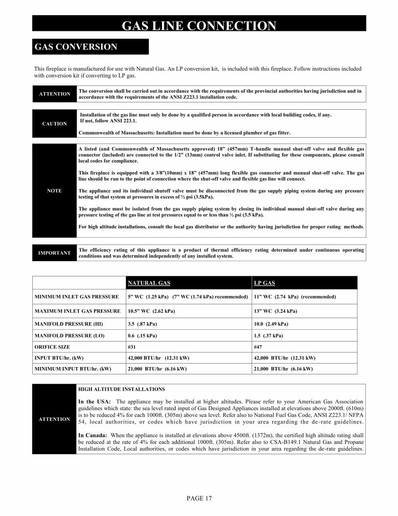
NATURAL GAS LP GAS
MINIMUM INLET GAS PRESSURE 5” WC (1.25 kPa) (7” WC (1.74 kPa) recommended) 11” WC (2.74 kPa) (recommended)
MAXIMUM INLET GAS PRESSURE 10.5” WC (2.62 kPa) 13” WC (3.24 kPa)
MANIFOLD PRESSURE (HI) 3.5 (.87 kPa) 10.0 (2.49 kPa)
MANIFOLD PRESSURE (LO) 0.6 (.15 kPa) 1.5 (.37 kPa)
ORIFICE SIZE #31 #47
INPUT BTU/hr. (kW) 42,000 BTU/hr (12.31 kW) 42,000 BTU/hr (12.31 kW)
MINIMUM INPUT BTU/hr. (kW) 21,000 BTU/hr (6.16 kW) 21,000 BTU/hr (6.16 kW)
ATTENTION The conversion shall be carried out in accordance with the requirements of the provincial authorities having jurisdiction and in
accordance with the requirements of the ANSI Z223.1 installation code.
CAUTION
Installation of the gas line must only be done by a qualified person in accordance with local building codes, if any.
If not, follow ANSI 223.1.
Commonwealth of Massachusetts: Installation must be done by a licensed plumber of gas fitter.
NOTE
A listed (and Commonwealth of Massachusetts approved) 18” (457mm) T-handle manual shut-off valve and flexible gas
connector (included) are connected to the 1/2” (13mm) control valve inlet. If substituting for these components, please consult
local codes for compliance.
This fireplace is equipped with a 3/8”(10mm) x 18” (457mm) long flexible gas connector and manual shut-off valve. The gas
line should be run to the point of connection where the shut-off valve and flexible gas line will connect.
The appliance and its individual shutoff valve must be disconnected from the gas supply piping system during any pressure
testing of that system at pressures in excess of ½ psi (3.5kPa).
The appliance must be isolated from the gas supply piping system by closing its individual manual shut-off valve during any
pressure testing of the gas line at test pressures equal to or less than ½ psi (3.5 kPa).
For high altitude installations, consult the local gas distributor or the authority having jurisdiction for proper rating methods.
IMPORTANT The efficiency rating of this appliance is a product of thermal efficiency rating determined under continuous operating
conditions and was determined independently of any installed system.
ATTENTION
HIGH ALTITUDE INSTALLATIONS
In the USA: The appliance may be installed at higher altitudes. Please refer to your American Gas Association
guidelines which state: the sea level rated input of Gas Designed Appliances installed at elevations above 2000ft. (610m)
is to be reduced 4% for each 1000ft. (305m) above sea level. Refer also to National Fuel Gas Code, ANSI Z223.1/ NFPA
54, local authorities, or codes which have jurisdiction in your area regarding the de -rate guidelines.
In Canada: When the appliance is installed at elevations above 4500ft. (1372m), the certified high altitude rating shall
be reduced at the rate of 4% for each additional 1000ft. (305m). Refer also to CSA-B149.1 Natural Gas and Propane
Installation Code, Local authorities, or codes which have jurisdiction in your area regarding the de-rate guidelines.
Simpson Dura-Vent DV-PRO 5” x 8” direct vent system (horizontal and vertical terminations).
Selkirk Metalbestos 5” x 8” direct vent chimney system (horizontal and vertical terminations).
Kozy Heat #800 series flexible vent system (horizontal terminations).
Metal Fab 5” x 8” direct vent chimney system (horizontal and vertical terminations).
ICC 5” x 8” direct vent chimney system (horizontal and vertical terminations).
Security 5” x 8” direct vent chimney system (horizontal and vertical terminations).
Amerivent / American Metal 5” x 8” direct vent chimney system (horizontal and vertical terminations).
BDM 5” x 8” direct vent chimney system (horizontal and vertical terminations).
RLH 5” x 8” direct vent chimney system (vertical terminations).
HORIZONTAL VENT SYSTEM CLEARANCES
TOP BOTTOM SIDES
ALL APPROVED VENTING 3 inches (76mm) 1 inch (25mm) 1 inch (25mm)
HORIZONTAL TERMINATIONS (NAT GAS)
MINIMUM: 12” (305mm) vertical rise + 90° elbow + 9” (229mm) horizontal + termination cap.
(Horizontal Vent Heat Shield required).
MAXIMUM: 12” (305mm) vertical rise + 90° elbow + 12ft. (3.66m) horizontal + termination cap.
(Horizontal Vent Heat Shield required).
VENTING
APPROVED VENTING
This fireplace is designed to be used with any of the following vent systems without the use of an additional adaptor.
Refer to vent manufacturer's installation manual for complete installation instructions. Installation must conform with venting requirements and
restrictions as outlined in this manual.
Provide a means for visually checking vent connection to fireplace after fireplace is installed.
PAGE 18
IMPORTANT Consult the local and national installation codes to assure adequate combustion and ventilation air is available.
IMPORTANT Kozy Heat Wall Pass-thru, #800-WPT (4-1/2” (114mm) - 6-1/2” (165mm) wall thickness),
or #800-WPT2 (6-1/2” (165mm) -12-1/2” (318mm) wall thickness) must be used on all horizontal vent runs.
IMPORTANT
The horizontal heat shield included with this fireplace must be installed when incorporating minimum horizontal venting. This
applies to Nat. and LP minimum horizontal venting configurations.
Flame height and appearance will vary depending upon venting configuration and type of fuel used.
HORIZONTAL TERMINATIONS (LP GAS)
MINIMUM*: 12” (305mm) vertical rise + 90° elbow + 9” (229mm) horizontal + termination cap.
(Horizontal Vent Heat Shield required).
MAXIMUM: 18” (457mm) vertical rise + 90° elbow / Max. 12ft. (3.66m) horizontal + termination cap.
(Horizontal Vent Heat Shield required).
*For horizontal runs greater than 2ft. (601mm): 18” (457mm) minimum vertical rise is required.
VENTING
#800-WPT WALL PASS-THRU
12-1/2” (318mm) HIGH x 10-7/8” (276mm) WIDE
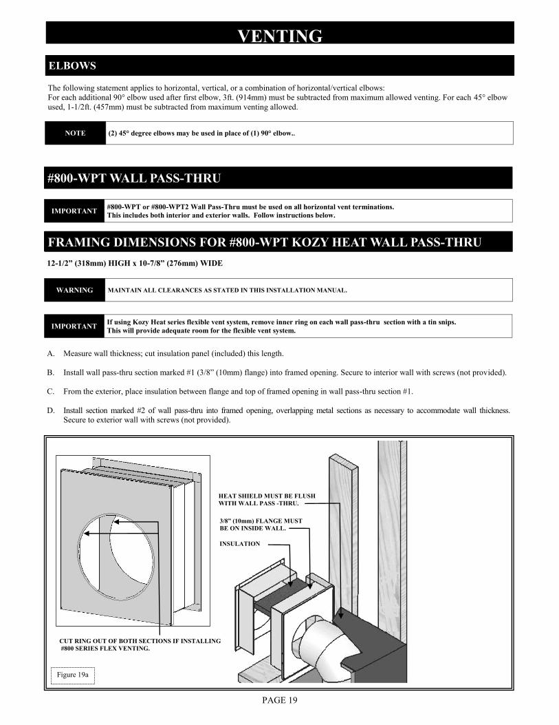
A. Measure wall thickness; cut insulation panel (included) this length.
B. Install wall pass-thru section marked #1 (3/8” (10mm) flange) into framed opening. Secure to interior wall with screws (not provided).
C. From the exterior, place insulation between flange and top of framed opening in wall pass-thru section #1.
D. Install section marked #2 of wall pass-thru into framed opening, overlapping metal sections as necessary to accommodate wall thickness.
Secure to exterior wall with screws (not provided).
FRAMING DIMENSIONS FOR #800-WPT KOZY HEAT WALL PASS-THRU
CUT RING OUT OF BOTH SECTIONS IF INSTALLING
#800 SERIES FLEX VENTING.
INSULATION
HEAT SHIELD MUST BE FLUSH
WITH WALL PASS -THRU.
PAGE 19
3/8” (10mm) FLANGE MUST
BE ON INSIDE WALL.
Figure 19a
IMPORTANT #800-WPT or #800-WPT2 Wall Pass-Thru must be used on all horizontal vent terminations.
This includes both interior and exterior walls. Follow instructions below.
WARNING MAINTAIN ALL CLEARANCES AS STATED IN THIS INSTALLATION MANUAL.
IMPORTANT If using Kozy Heat series flexible vent system, remove inner ring on each wall pass-thru section with a tin snips.
This will provide adequate room for the flexible vent system.
The following statement applies to horizontal, vertical, or a combination of horizontal/vertical elbows:
For each additional 90° elbow used after first elbow, 3ft. (914mm) must be subtracted from maximum allowed venting. For each 45° elbow
used, 1-1/2ft. (457mm) must be subtracted from maximum venting allowed.
ELBOWS
NOTE (2) 45° degree elbows may be used in place of (1) 90° elbow..
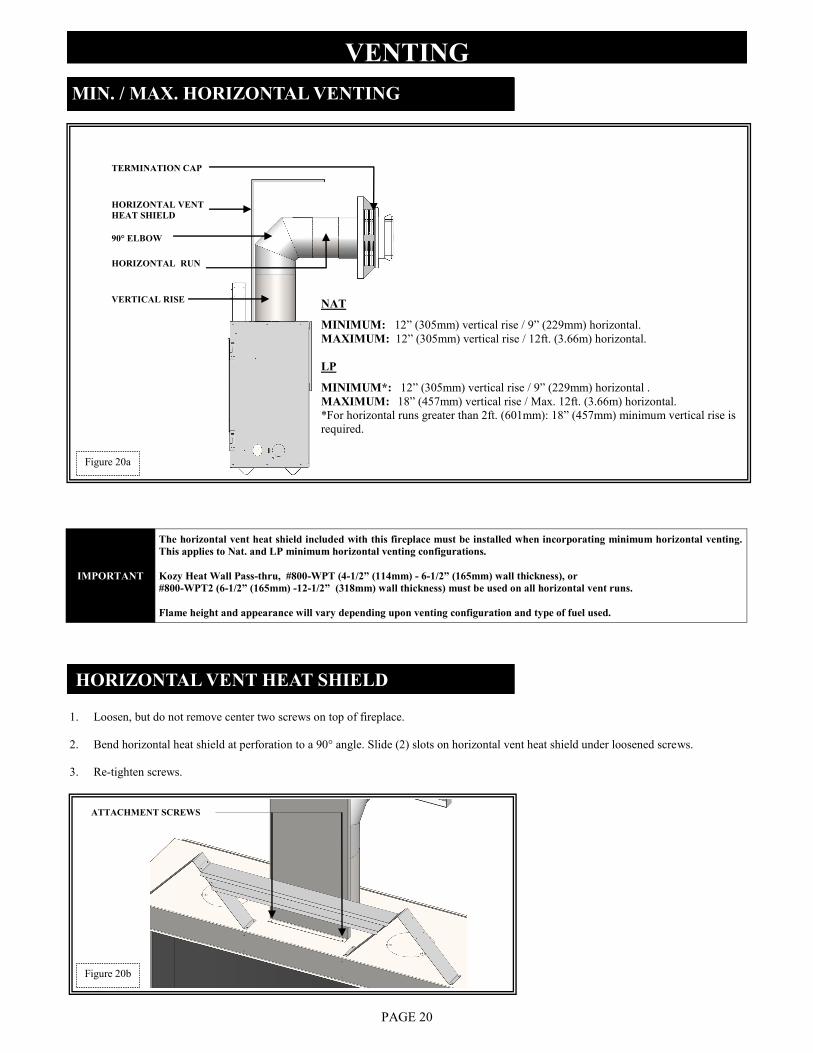
VENTING MIN. / MAX. HORIZONTAL VENTING
90° ELBOW
HORIZONTAL VENT
HEAT SHIELD
TERMINATION CAP
PAGE 20
HORIZONTAL VENT HEAT SHIELD
1. Loosen, but do not remove center two screws on top of fireplace.
2. Bend horizontal heat shield at perforation to a 90° angle. Slide (2) slots on horizontal vent heat shield under loosened screws.
3. Re-tighten screws.
ATTACHMENT SCREWS
Figure 20b
NAT
MINIMUM: 12” (305mm) vertical rise / 9” (229mm) horizontal.
MAXIMUM: 12” (305mm) vertical rise / 12ft. (3.66m) horizontal.
LP
MINIMUM*: 12” (305mm) vertical rise / 9” (229mm) horizontal .
MAXIMUM: 18” (457mm) vertical rise / Max. 12ft. (3.66m) horizontal.
*For horizontal runs greater than 2ft. (601mm): 18” (457mm) minimum vertical rise is
required.
HORIZONTAL RUN
VERTICAL RISE
IMPORTANT
The horizontal vent heat shield included with this fireplace must be installed when incorporating minimum horizontal venting.
This applies to Nat. and LP minimum horizontal venting configurations.
Kozy Heat Wall Pass-thru, #800-WPT (4-1/2” (114mm) - 6-1/2” (165mm) wall thickness), or
#800-WPT2 (6-1/2” (165mm) -12-1/2” (318mm) wall thickness) must be used on all horizontal vent runs.
Flame height and appearance will vary depending upon venting configuration and type of fuel used.
Figure 20a
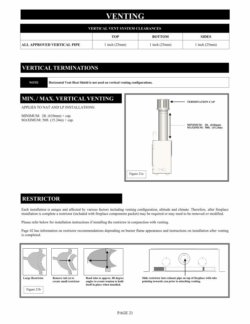
APPLIES TO NAT AND LP INSTALLATIONS:
MINIMUM: 2ft. (610mm) + cap.
MAXIMUM: 50ft. (15.24m) + cap.
Each installation is unique and affected by various factors including venting configuration, altitude and climate. Therefore, after fireplace
installation is complete a restrictor (included with fireplace components packet) may be required or may need to be removed or modified.
Please refer below for installation instructions if installing the restrictor in conjunction with venting.
Page 42 has information on restrictor recommendations depending on burner flame appearance and instructions on installation after venting
is completed.
RESTRICTOR
VERTICAL VENT SYSTEM CLEARANCES
TOP BOTTOM SIDES
ALL APPROVED VERTICAL PIPE 1 inch (25mm) 1 inch (25mm) 1 inch (25mm)
VERTICAL TERMINATIONS
MIN. / MAX. VERTICAL VENTING
VENTING
MINIMUM: 2ft. (610mm) MAXIMUM: 50ft. (15.24m)
PAGE 21
TERMINATION CAP
Slide restrictor into exhaust pipe on top of fireplace with tabs
pointing towards you prior to attaching venting.
Large Restrictor Remove tab (s) to
create small restrictor
Bend tabs to approx. 80 degree
angles to create tension to hold
itself in place when installed.
Figure 21b
Figure 21a
NOTE Horizontal Vent Heat Shield is not used on vertical venting configurations.
For each additional 90° elbow used after first elbow, 3ft. (914mm) must be subtracted from maximum allowed venting.
For each 45° elbow used, 1-1/2ft. (457mm) must be subtracted from maximum venting allowed.
(2) 45° degree elbows may be used in place of (1) 90° elbow.
The horizontal vent heat shield must be installed when using a 90-degree elbow to horizontally position the vent system.
Kozy Heat Wall Pass-thru, #800-WPT (4-1/2” (114mm) - 6-1/2” (165mm) wall thickness) or,
#800-WPT2 (6-1/2” (165mm) - 12-1/2” (318mm) wall thickness), must be used on all horizontal vent runs.
Horizontal sections require 1/4” (6mm) rise for every 12” (305mm) of travel.
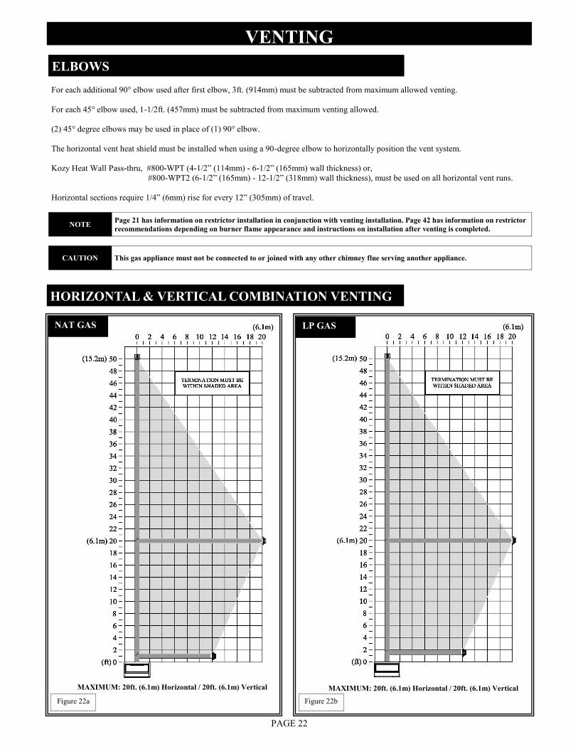
HORIZONTAL & VERTICAL COMBINATION VENTING
ELBOWS
VENTING
PAGE 22
Figure 22b Figure 22a
NOTE Page 21 has information on restrictor installation in conjunction with venting installation. Page 42 has information on restrictor
recommendations depending on burner flame appearance and instructions on installation after venting is completed.
CAUTION This gas appliance must not be connected to or joined with any other chimney flue serving another appliance.
NAT GAS
MAXIMUM: 20ft. (6.1m) Horizontal / 20ft. (6.1m) Vertical
LP GAS
MAXIMUM: 20ft. (6.1m) Horizontal / 20ft. (6.1m) Vertical
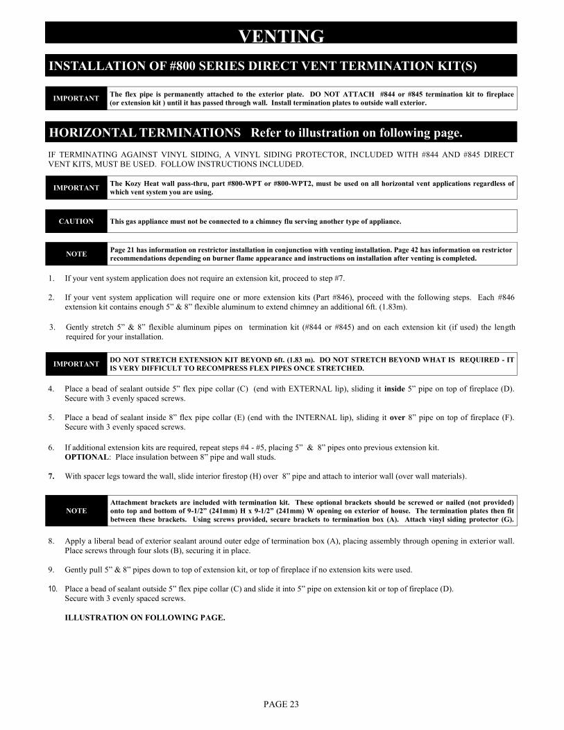
VENTING INSTALLATION OF #800 SERIES DIRECT VENT TERMINATION KIT(S)
HORIZONTAL TERMINATIONS Refer to illustration on following page.
IF TERMINATING AGAINST VINYL SIDING, A VINYL SIDING PROTECTOR, INCLUDED WITH #844 AND #845 DIRECT
VENT KITS, MUST BE USED. FOLLOW INSTRUCTIONS INCLUDED.
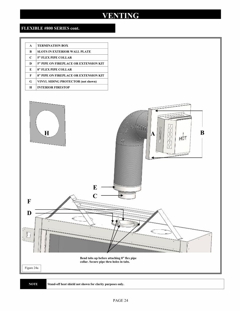
1. If your vent system application does not require an extension kit, proceed to step #7.
2. If your vent system application will require one or more extension kits (Part #846), proceed with the following steps. Each #846
extension kit contains enough 5” & 8” flexible aluminum to extend chimney an additional 6ft. (1.83m).
3. Gently stretch 5” & 8” flexible aluminum pipes on termination kit (#844 or #845) and on each extension kit (if used) the length
required for your installation.
PAGE 23
6. If additional extension kits are required, repeat steps #4 - #5, placing 5” & 8” pipes onto previous extension kit.
OPTIONAL: Place insulation between 8” pipe and wall studs.
7. With spacer legs toward the wall, slide interior firestop (H) over 8” pipe and attach to interior wall (over wall materials).
8. Apply a liberal bead of exterior sealant around outer edge of termination box (A), placing assembly through opening in exterior wall.
Place screws through four slots (B), securing it in place.
9. Gently pull 5” & 8” pipes down to top of extension kit, or top of fireplace if no extension kits were used.
10. Place a bead of sealant outside 5” flex pipe collar (C) and slide it into 5” pipe on extension kit or top of fireplace (D).
Secure with 3 evenly spaced screws.
ILLUSTRATION ON FOLLOWING PAGE.
4. Place a bead of sealant outside 5” flex pipe collar (C) (end with EXTERNAL lip), sliding it inside 5” pipe on top of fireplace (D).
Secure with 3 evenly spaced screws.
5. Place a bead of sealant inside 8” flex pipe collar (E) (end with the INTERNAL lip), sliding it over 8” pipe on top of fireplace (F).
Secure with 3 evenly spaced screws.
IMPORTANT The flex pipe is permanently attached to the exterior plate. DO NOT ATTACH #844 or #845 termination kit to fireplace
(or extension kit ) until it has passed through wall. Install termination plates to outside wall exterior.
IMPORTANT The Kozy Heat wall pass-thru, part #800-WPT or #800-WPT2, must be used on all horizontal vent applications regardless of
which vent system you are using.
CAUTION This gas appliance must not be connected to a chimney flu serving another type of appliance.
NOTE Page 21 has information on restrictor installation in conjunction with venting installation. Page 42 has information on restrictor
recommendations depending on burner flame appearance and instructions on installation after venting is completed.
IMPORTANT DO NOT STRETCH EXTENSION KIT BEYOND 6ft. (1.83 m). DO NOT STRETCH BEYOND WHAT IS REQUIRED - IT
IS VERY DIFFICULT TO RECOMPRESS FLEX PIPES ONCE STRETCHED.
NOTE
Attachment brackets are included with termination kit. These optional brackets should be screwed or nailed (not provided)
onto top and bottom of 9-1/2” (241mm) H x 9-1/2” (241mm) W opening on exterior of house. The termination plates then fit
between these brackets. Using screws provided, secure brackets to termination box (A). Attach vinyl siding protector (G).
VENTING
F
D
A
E
C
H
PAGE 24
A TERMINATION BOX
B SLOTS IN EXTERIOR WALL PLATE
C 5” FLEX PIPE COLLAR
D 5” PIPE ON FIREPLACE OR EXTENSION KIT
E 8” FLEX PIPE COLLAR
F 8” PIPE ON FIREPLACE OR EXTENSION KIT
G VINYL SIDING PROTECTOR (not shown)
H INTERIOR FIRESTOP
FLEXIBLE #800 SERIES cont.
Bend tabs up before attaching 8” flex pipe
collar. Secure pipe thru holes in tabs.
Figure 24a
NOTE Stand-off heat shield not shown for clarity purposes only.
B
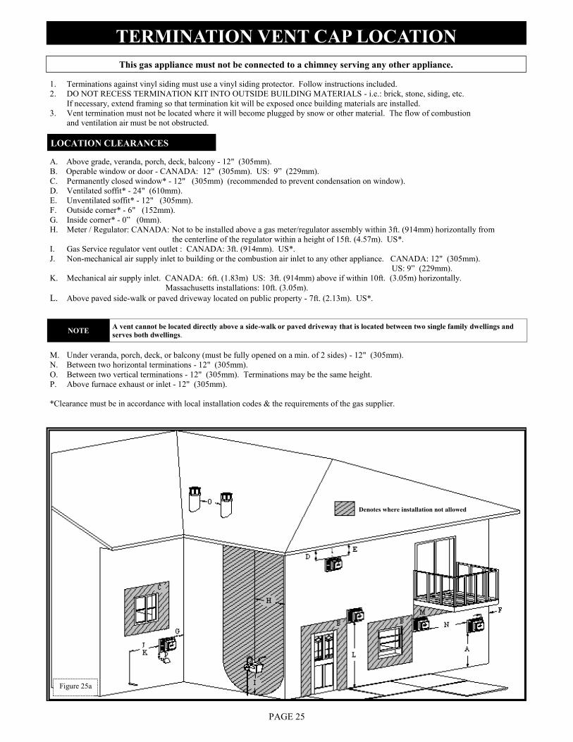
1. Terminations against vinyl siding must use a vinyl siding protector. Follow instructions included.
2. DO NOT RECESS TERMINATION KIT INTO OUTSIDE BUILDING MATERIALS - i.e.: brick, stone, siding, etc.
If necessary, extend framing so that termination kit will be exposed once building materials are installed.
3. Vent termination must not be located where it will become plugged by snow or other material. The flow of combustion
and ventilation air must be not obstructed.
A. Above grade, veranda, porch, deck, balcony - 12" (305mm).
B. Operable window or door - CANADA: 12" (305mm). US: 9” (229mm).
C. Permanently closed window* - 12" (305mm) (recommended to prevent condensation on window).
D. Ventilated soffit* - 24" (610mm).
E. Unventilated soffit* - 12" (305mm).
F. Outside corner* - 6" (152mm).
G. Inside corner* - 0” (0mm).
H. Meter / Regulator: CANADA: Not to be installed above a gas meter/regulator assembly within 3ft. (914mm) horizontally from
the centerline of the regulator within a height of 15ft. (4.57m). US*.
I. Gas Service regulator vent outlet : CANADA: 3ft. (914mm). US*.
J. Non-mechanical air supply inlet to building or the combustion air inlet to any other appliance. CANADA: 12" (305mm).
US: 9” (229mm).
K. Mechanical air supply inlet. CANADA: 6ft. (1.83m) US: 3ft. (914mm) above if within 10ft. (3.05m) horizontally.
Massachusetts installations: 10ft. (3.05m).
L. Above paved side-walk or paved driveway located on public property - 7ft. (2.13m). US*.
This gas appliance must not be connected to a chimney serving any other appliance.
TERMINATION VENT CAP LOCATION
LOCATION CLEARANCES
M. Under veranda, porch, deck, or balcony (must be fully opened on a min. of 2 sides) - 12" (305mm).
N. Between two horizontal terminations - 12" (305mm).
O. Between two vertical terminations - 12" (305mm). Terminations may be the same height.
P. Above furnace exhaust or inlet - 12" (305mm).
*Clearance must be in accordance with local installation codes & the requirements of the gas supplier.
PAGE 25
Denotes where installation not allowed
Figure 25a
NOTE A vent cannot be located directly above a side-walk or paved driveway that is located between two single family dwellings and
serves both dwellings.
PAGE 26
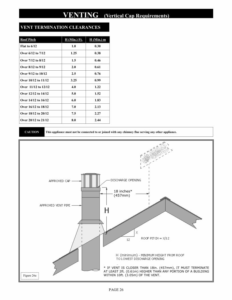
Roof Pitch H (Min.) Ft. H (Min.) m
Flat to 6/12 1.0 0.30
Over 6/12 to 7/12 1.25 0.38
Over 7/12 to 8/12 1.5 0.46
Over 8/12 to 9/12 2.0 0.61
Over 9/12 to 10/12 2.5 0.76
Over 10/12 to 11/12 3.25 0.99
Over 11/12 to 12/12 4.0 1.22
Over 12/12 to 14/12 5.0 1.52
Over 14/12 to 16/12 6.0 1.83
Over 16/12 to 18/12 7.0 2.13
Over 18/12 to 20/12 7.5 2.27
Over 20/12 to 21/12 8.0 2.44
VENT TERMINATION CLEARANCES
VENTING (Vertical Cap Requirements)
18 inches*(457mm)
* IF VENT IS CLOSER THAN 18in. (457mm), IT MUST TERMINATE AT LEAST 2ft. (0.61m) HIGHER THAN ANY PORTION OF A BUILDING WITHIN 10ft. (3.05m) OF THE VENT. Figure 26a
CAUTION This appliance must not be connected to or joined with any chimney flue serving any other appliance.
LIGHT KIT
PAGE 27
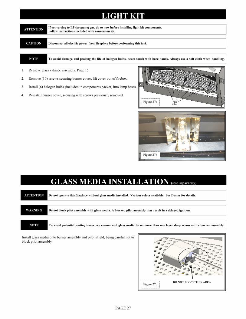
1. Remove glass valance assembly. Page 15.
2. Remove (10) screws securing burner cover, lift cover out of firebox.
3. Install (6) halogen bulbs (included in components packet) into lamp bases.
4. Reinstall burner cover, securing with screws previously removed.
GLASS MEDIA INSTALLATION (sold separately)
Install glass media onto burner assembly and pilot shield, being careful not to
block pilot assembly.
DO NOT BLOCK THIS AREA
ATTENTION If converting to LP (propane) gas, do so now before installing light kit components.
Follow instructions included with conversion kit.
CAUTION Disconnect all electric power from fireplace before performing this task.
NOTE To avoid damage and prolong the life of halogen bulbs, never touch with bare hands. Always use a soft cloth when handling.
ATTENTION Do not operate this fireplace without glass media installed. Various colors available. See Dealer for details.
WARNING Do not block pilot assembly with glass media. A blocked pilot assembly may result in a delayed ignition.
NOTE To avoid potential sooting issues, we recommend glass media be no more than one layer deep across entire burner assembly.
Figure 27a
Figure 27b
Figure 27c
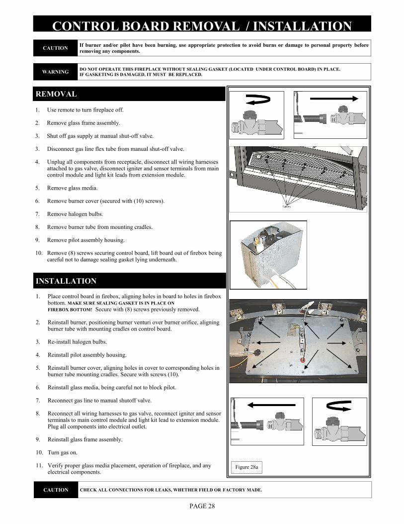
CONTROL BOARD REMOVAL / INSTALLATION
1. Use remote to turn fireplace off.
2. Remove glass frame assembly.
3. Shut off gas supply at manual shut-off valve.
3. Disconnect gas line flex tube from manual shut-off valve.
4. Unplug all components from receptacle, disconnect all wiring harnesses attached to gas valve, disconnect igniter and sensor terminals from main control module and light kit leads from extension module.
5. Remove glass media.
6. Remove burner cover (secured with (10) screws).
7. Remove halogen bulbs.
8. Remove burner tube from mounting cradles.
9. Remove pilot assembly housing.
10. Remove (8) screws securing control board, lift board out of firebox being careful not to damage sealing gasket lying underneath.
PAGE 28
REMOVAL
INSTALLATION
1. Place control board in firebox, aligning holes in board to holes in firebox bottom. MAKE SURE SEALING GASKET IS IN PLACE ON
FIREBOX BOTTOM! Secure with (8) screws previously removed.
2. Reinstall burner, positioning burner venturi over burner orifice, aligning burner tube with mounting cradles on control board.
3. Re-install halogen bulbs.
4. Reinstall pilot assembly housing.
5. Reinstall burner cover, aligning holes in cover to corresponding holes in burner tube mounting cradles. Secure with screws (10).
6. Reinstall glass media, being careful not to block pilot.
7. Reconnect gas line to manual shutoff valve.
8. Reconnect all wiring harnesses to gas valve, reconnect igniter and sensor terminals to main control module and light kit lead to extension module. Plug all components into electrical outlet.
9. Reinstall glass frame assembly.
10. Turn gas on.
11. Verify proper glass media placement, operation of fireplace, and any electrical components.
CAUTION If burner and/or pilot have been burning, use appropriate protection to avoid burns or damage to personal property before
removing any components.
WARNING DO NOT OPERATE THIS FIREPLACE WITHOUT SEALING GASKET (LOCATED UNDER CONTROL BOARD) IN PLACE.
IF GASKETING IS DAMAGED, IT MUST BE REPLACED.
CAUTION CHECK ALL CONNECTIONS FOR LEAKS, WHETHER FIELD OR FACTORY MADE.
Figure 28a
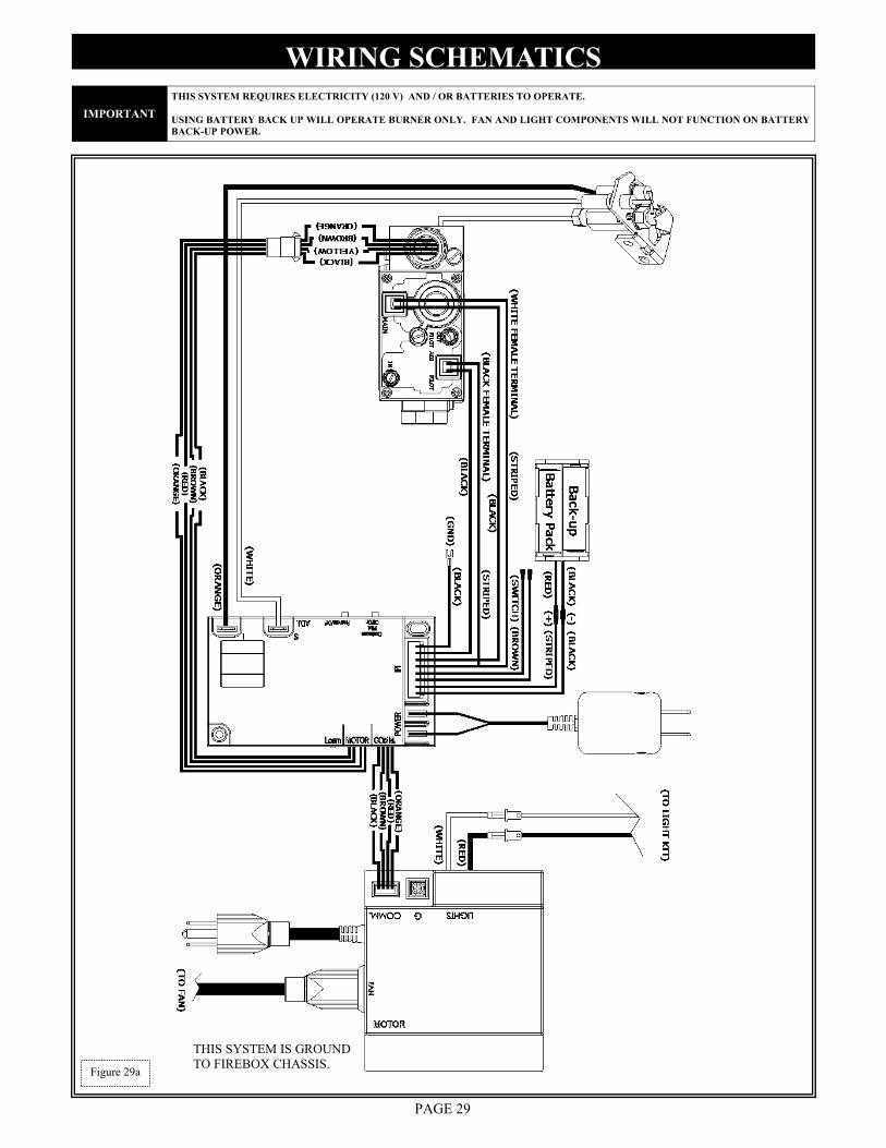
WIRING SCHEMATICS
PAGE 29
Figure 29a
IMPORTANT
THIS SYSTEM REQUIRES ELECTRICITY (120 V) AND / OR BATTERIES TO OPERATE.
USING BATTERY BACK UP WILL OPERATE BURNER ONLY. FAN AND LIGHT COMPONENTS WILL NOT FUNCTION ON BATTERY
BACK-UP POWER.
THIS SYSTEM IS GROUND
TO FIREBOX CHASSIS.
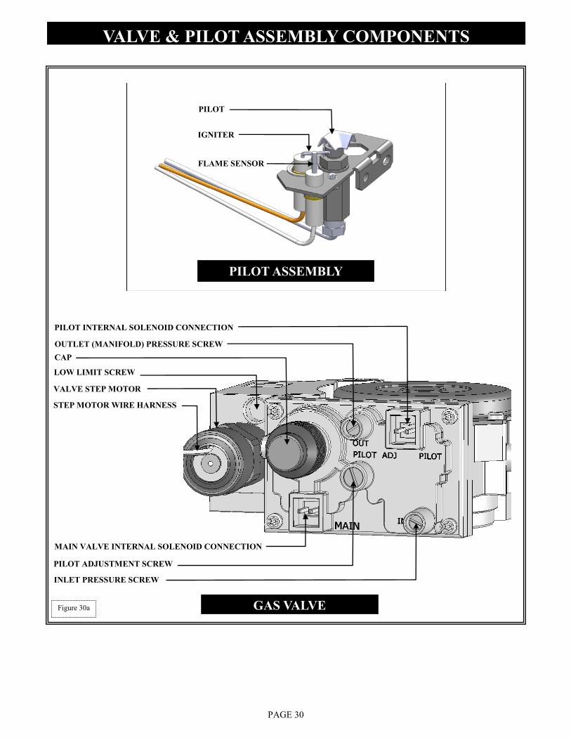
VALVE & PILOT ASSEMBLY COMPONENTS
PAGE 30
CAP
VALVE STEP MOTOR
LOW LIMIT SCREW
STEP MOTOR WIRE HARNESS
MAIN VALVE INTERNAL SOLENOID CONNECTION
PILOT INTERNAL SOLENOID CONNECTION
PILOT ADJUSTMENT SCREW
INLET PRESSURE SCREW
OUTLET (MANIFOLD) PRESSURE SCREW
GAS VALVE
IGNITER
PILOT
FLAME SENSOR
PILOT ASSEMBLY
Figure 30a
PAGE 31
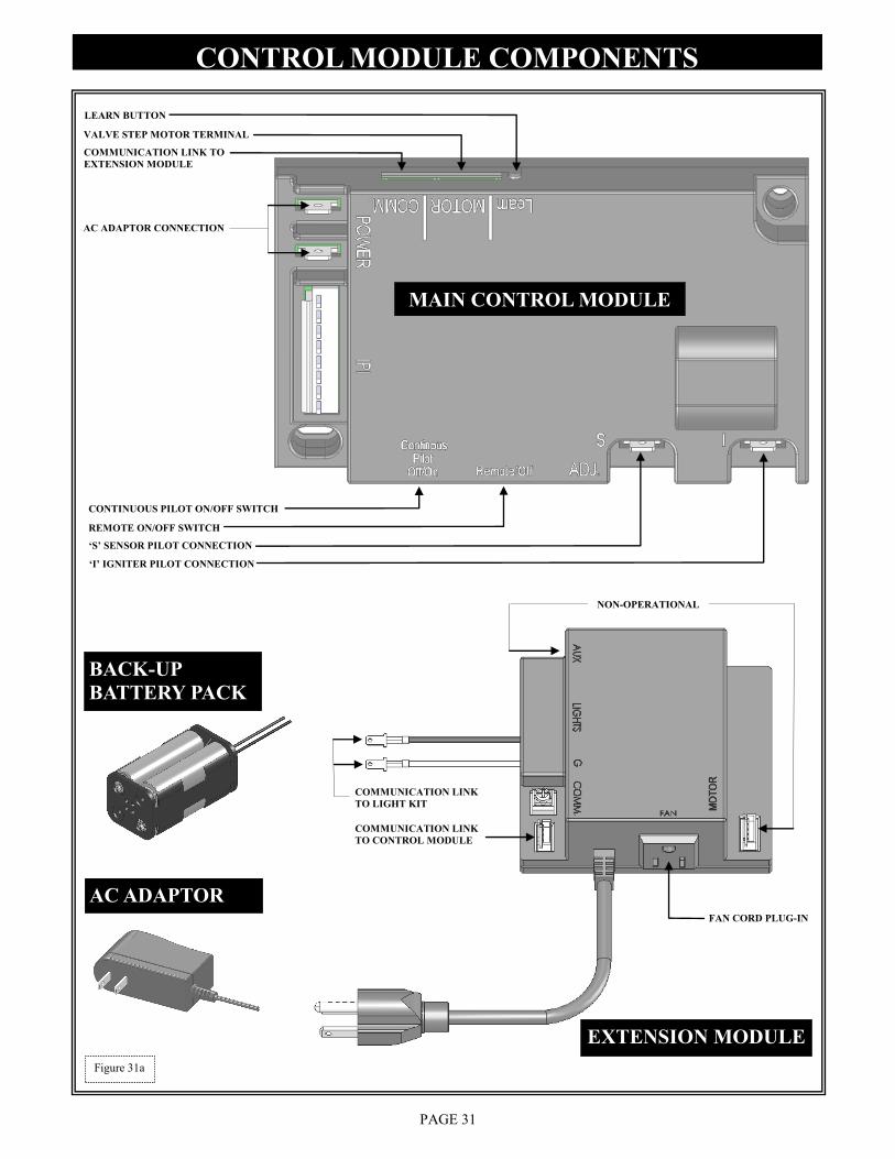
CONTROL MODULE COMPONENTS
„S‟ SENSOR PILOT CONNECTION
„I‟ IGNITER PILOT CONNECTION
REMOTE ON/OFF SWITCH
CONTINUOUS PILOT ON/OFF SWITCH
LEARN BUTTON
MAIN CONTROL MODULE
VALVE STEP MOTOR TERMINAL
COMMUNICATION LINK TO
EXTENSION MODULE
AC ADAPTOR CONNECTION
EXTENSION MODULE
COMMUNICATION LINK
TO CONTROL MODULE
FAN CORD PLUG-IN
BACK-UP
BATTERY PACK
AC ADAPTOR
COMMUNICATION LINK
TO LIGHT KIT
NON-OPERATIONAL
Figure 31a
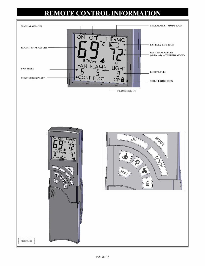
REMOTE CONTROL INFORMATION
PAGE 32
CHILD PROOF ICON
LIGHT LEVEL
FLAME HEIGHT
FAN SPEED
BATTERY LIFE ICON
THERMOSTAT MODE ICON
SET TEMPERATURE
(visible only in THERMO MODE)
MANUAL ON / OFF
ROOM TEMPERATURE
CONTINUOUS PILOT
Figure 32a
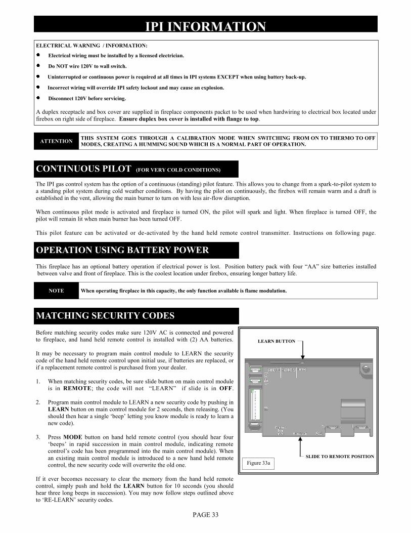
IPI INFORMATION
PAGE 33
ELECTRICAL WARNING / INFORMATION:
Electrical wiring must be installed by a licensed electrician.
Do NOT wire 120V to wall switch.
Uninterrupted or continuous power is required at all times in IPI systems EXCEPT when using battery back-up.
Incorrect wiring will override IPI safety lockout and may cause an explosion.
Disconnect 120V before servicing.
A duplex receptacle and box cover are supplied in fireplace components packet to be used when hardwiring to electrical box located under
firebox on right side of fireplace. Ensure duplex box cover is installed with flange to top.
The IPI gas control system has the option of a continuous (standing) pilot feature. This allows you to change from a spark-to-pilot system to
a standing pilot system during cold weather conditions. By having the pilot on continuously, the firebox will remain warm and a draft is
established in the vent, allowing the main burner to turn on with less air-flow disruption.
When continuous pilot mode is activated and fireplace is turned ON, the pilot will spark and light. When fireplace is turned OFF, the
pilot will remain lit when main burner has been turned OFF.
This pilot feature can be activated or de-activated by the hand held remote control transmitter. Instructions on following page.
CONTINUOUS PILOT (FOR VERY COLD CONDITIONS)
OPERATION USING BATTERY POWER
This fireplace has an optional battery operation if electrical power is lost. Position battery pack with four “AA” size batteries installed
between valve and front of fireplace. This is the coolest location under firebox, ensuring longer battery life.
Before matching security codes make sure 120V AC is connected and powered
to fireplace, and hand held remote control is installed with (2) AA batteries.
It may be necessary to program main control module to LEARN the security
code of the hand held remote control upon initial use, if batteries are replaced, or
if a replacement remote control is purchased from your dealer.
1. When matching security codes, be sure slide button on main control module
is in REMOTE; the code will not “LEARN” if slide is in OFF.
2. Program main control module to LEARN a new security code by pushing in
LEARN button on main control module for 2 seconds, then releasing. (You
should then hear a single „beep‟ letting you know module is ready to learn a
new code).
3. Press MODE button on hand held remote control (you should hear four
„beeps‟ in rapid succession in main control module, indicating remote
control‟s code has been programmed into the main control module). When
an existing main control module is introduced to a new hand held remote
control, the new security code will overwrite the old one.
If it ever becomes necessary to clear the memory from the hand held remote
control, simply push and hold the LEARN button for 10 seconds (you should
hear three long beeps in succession). You may now follow steps outlined above
to „RE-LEARN‟ security codes.
MATCHING SECURITY CODES
LEARN BUTTON
SLIDE TO REMOTE POSITION
Figure 33a
ATTENTION THIS SYSTEM GOES THROUGH A CALIBRATION MODE WHEN SWITCHING FROM ON TO THERMO TO OFF
MODES, CREATING A HUMMING SOUND WHICH IS A NORMAL PART OF OPERATION.
NOTE When operating fireplace in this capacity, the only function available is flame modulation.
REMOTE CONTROL OPERATION
PAGE 34
INITIAL SET-UP:
Plug Extension Module and AC Adaptor into receptacles.
Install (4) AAA batteries into battery compartment of Backup Battery Pack, making sure batteries are installed in proper direction.
Position between valve and front of stove. A Velcro strip has been attached to help secure in place.
The Hand Held Remote operates on (2) 1.5V AAA batteries. We recommend always using ALKALINE batteries to extend battery life
and improve operational performance.
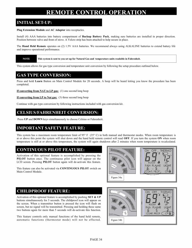
CONTINUOUS PILOT FEATURE:
Activation of this optional feature is accomplished by pressing the
PILOT button once. The continuous pilot icon will appear on the
LCD screen. Pressing PILOT button again will de-activate this feature.
This feature can also be activated via CONTINUOUS PILOT switch on
Main Control Module.
CHILDPROOF FEATURE:
Activation of this optional feature is accomplished by pushing SET & UP
buttons simultaneously for 5 seconds. The childproof icon will appear on
the screen. When a transmitter button is pressed the icon will flash on
screen, but no signal will be transmitted. Pressing and holding these same
two buttons again for more than 5 seconds will de-activate this function.
This feature controls only manual functions of the hand held remote,
automatic functions (thermostat mode) will not be effected.
CELSIUS/FAHRENHEIT CONVERSION:
GAS TYPE CONVERSION:
Press and hold Learn Button on Main Control Module for 20 seconds. A beep will be heard letting you know the procedure has been
completed.
If converting from NAT to LP gas: (1) one second long beep
If converting from LP to Nat gas: (3) three second long beep
Continue with gas type conversion by following instructions included with gas conversion kit.
Press UP and DOWN keys simultaneously to choose Celsius or Fahrenheit.
This system allows for gas type conversion and temperature unit conversion by following the setup procedure outlined below.
This system has a maximum room temperature limit of 95° F (35° C) in both manual and thermostat modes. When room temperature is
at or above this point the system will shut down and the hand held remote control will read OFF. If you turn the system ON when room
temperature is still at or above this temperature, the system will again shutdown after 2 minutes when room temperature is recalculated.
IMPORTANT SAFETY FEATURE:
Figure 34b
Figure 34a
NOTE This system is sent to you set up for Natural Gas and temperature units readable in Fahrenheit.
REMOTE CONTROL INFORMATION cont.
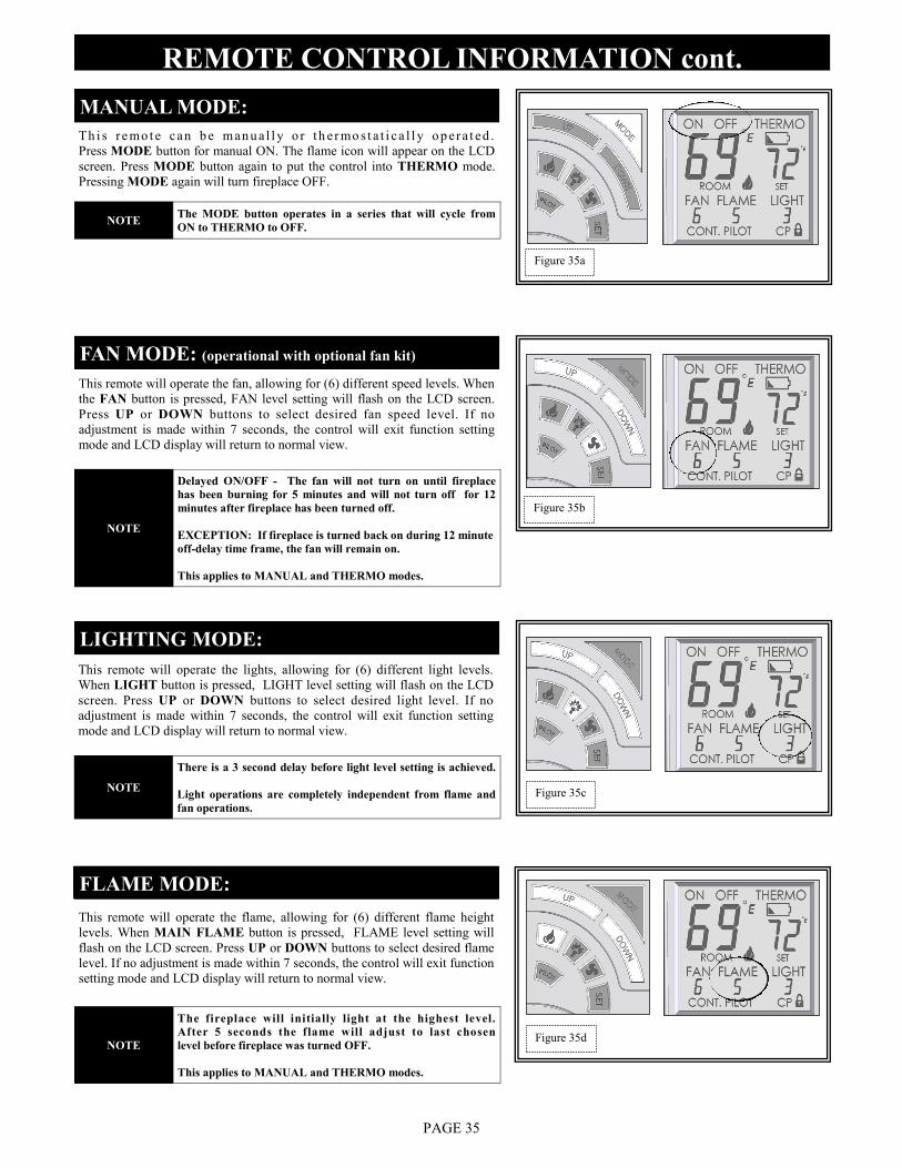
MANUAL MODE:
Th i s r e mo t e can b e man u a l l y o r t h e r mo s t a t i ca l l y o p era t ed .
Press MODE button for manual ON. The flame icon will appear on the LCD
screen. Press MODE button again to put the control into THERMO mode.
Pressing MODE again will turn fireplace OFF.
FAN MODE: (operational with optional fan kit)
This remote will operate the fan, allowing for (6) different speed levels. When
the FAN button is pressed, FAN level setting will flash on the LCD screen.
Press UP or DOWN buttons to select desired fan speed level. If no
adjustment is made within 7 seconds, the control will exit function setting
mode and LCD display will return to normal view.
LIGHTING MODE:
This remote will operate the lights, allowing for (6) different light levels.
When LIGHT button is pressed, LIGHT level setting will flash on the LCD
screen. Press UP or DOWN buttons to select desired light level. If no
adjustment is made within 7 seconds, the control will exit function setting
mode and LCD display will return to normal view.
FLAME MODE:
This remote will operate the flame, allowing for (6) different flame height
levels. When MAIN FLAME button is pressed, FLAME level setting will
flash on the LCD screen. Press UP or DOWN buttons to select desired flame
level. If no adjustment is made within 7 seconds, the control will exit function
setting mode and LCD display will return to normal view.
PAGE 35
Figure 35d
Figure 35c
Figure 35b
Figure 35a
NOTE The MODE button operates in a series that will cycle from
ON to THERMO to OFF.
NOTE
Delayed ON/OFF - The fan will not turn on until fireplace
has been burning for 5 minutes and will not turn off for 12
minutes after fireplace has been turned off.
EXCEPTION: If fireplace is turned back on during 12 minute
off-delay time frame, the fan will remain on.
This applies to MANUAL and THERMO modes.
NOTE
There is a 3 second delay before light level setting is achieved.
Light operations are completely independent from flame and
fan operations.
NOTE
The fireplace will initially light at the highest level.
After 5 seconds the flame will adjust to last chosen
level before fireplace was turned OFF.
This applies to MANUAL and THERMO modes.
REMOTE CONTROL INFORMATION cont.
PAGE 36
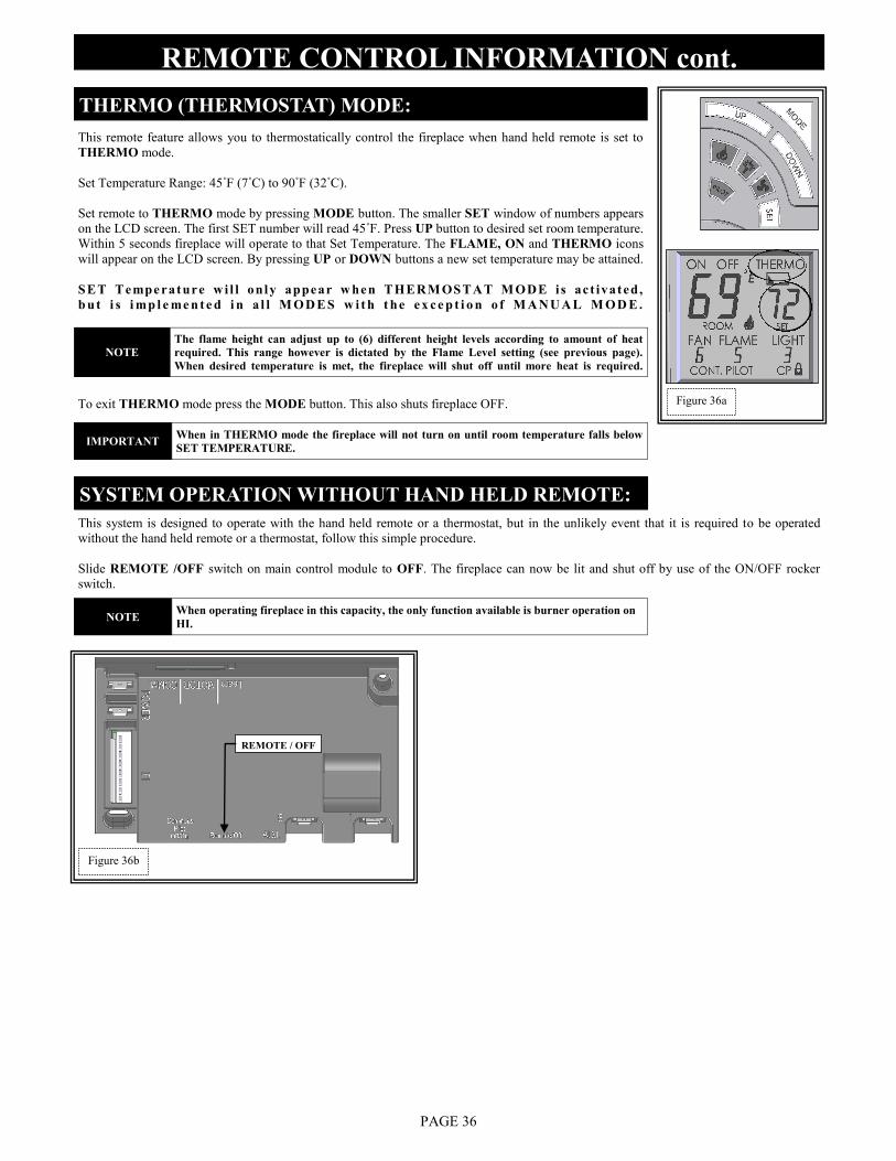
THERMO (THERMOSTAT) MODE:
This remote feature allows you to thermostatically control the fireplace when hand held remote is set to
THERMO mode.
Set Temperature Range: 45˚F (7˚C) to 90˚F (32˚C).
Set remote to THERMO mode by pressing MODE button. The smaller SET window of numbers appears
on the LCD screen. The first SET number will read 45˚F. Press UP button to desired set room temperature.
Within 5 seconds fireplace will operate to that Set Temperature. The FLAME, ON and THERMO icons
will appear on the LCD screen. By pressing UP or DOWN buttons a new set temperature may be attained.
SET Tempe rature w i l l only appear w hen THERM OSTAT M ODE i s ac t ivated,
b u t i s i mp l e me n t e d i n a l l M O D E S w i t h t he e x c e p t i o n o f M A N U A L M O D E .
To exit THERMO mode press the MODE button. This also shuts fireplace OFF.
SYSTEM OPERATION WITHOUT HAND HELD REMOTE:
This system is designed to operate with the hand held remote or a thermostat, but in the unlikely event that it is required to be operated
without the hand held remote or a thermostat, follow this simple procedure.
Slide REMOTE /OFF switch on main control module to OFF. The fireplace can now be lit and shut off by use of the ON/OFF rocker
switch.
REMOTE / OFF
Figure 36b
Figure 36a
NOTE
The flame height can adjust up to (6) different height levels according to amount of heat
required. This range however is dictated by the Flame Level setting (see previous page).
When desired temperature is met, the fireplace will shut off until more heat is required.
IMPORTANT When in THERMO mode the fireplace will not turn on until room temperature falls below
SET TEMPERATURE.
NOTE When operating fireplace in this capacity, the only function available is burner operation on
HI.
FOR YOUR SAFETY - READ BEFORE OPERATING
LIGHTING AND SHUTDOWN
PAGE 37
WARNING IF YOU DO NOT FOLLOW THESE INSTRUCTIONS EXACTLY, A FIRE OR EXPLOSION MAY RESULT, CAUSING
PROPERTY DAMAGE, PERSONAL INJURY OR LOSS OF LIFE.
WARNING
CHILDREN AND ADULTS SHOULD BE ALERTED TO THE HAZARDS OF HIGH SURFACE TEMPERATURES AND
SHOULD STAY AWAY TO AVOID BURNS OR CLOTHING IGNITION. YOUNG CHILDREN SHOULD BE CAREFULLY
SUPERVISED WHEN THEY ARE IN THE SAME ROOM AS THE APPLIANCE. CLOTHING OR OTHER FLAMMABLE
MATERIAL MUST NOT BE PLACED ON OR NEAR THE APPLIANCE.
NOTE
A PAINT SMELL WILL OCCUR DURING THE FIRST FEW HOURS OF BURNING. IT IS RECOMMENDED TO LEAVE
THE FAN OFF DURING THIS PERIOD TO HELP SPEED THE PAINT CURING PROCESS.
THIS FIREPLACE MAY PRODUCE NOISES OF VARYING DEGREE AS IT HEATS AND COOLS DUE TO METAL
EXPANSION AND CONTRACTION. THIS IS NORMAL AND DOES NOT AFFECT THE PERFORMANCE OR
LONGEVITY OF THE FIREPLACE.
1. This appliance is equipped with an ignition device which automatically lights the pilot. DO NOT try to light the pilot by hand.
2. BEFORE LIGHTING, smell all around the appliance area for gas. Be sure to smell next to the floor because some gas is heavier than
air and will settle on the floor.
WHAT TO DO IF YOU SMELL GAS:
* Do not try to light any appliance.
* Do not touch any electrical switches; do not use the phone in your building.
* Immediately call your gas supplier from a neighbor‟s phone. Follow the gas supplier‟s instructions.
* If you cannot reach your gas supplier, call the fire department.
3. Do not use this appliance if any part has been under water. Immediately call a qualified service technician to inspect the appliance and
to replace any part of the control system and any gas control which has been under water.
DUE TO HIGH SURFACE TEMPERATURES, KEEP CHILDREN, CLOTHING AND FURNITURE AWAY.
This appliance needs fresh air for safe operation and must be installed so there are provisions for adequate combustion and ventilation air.
DO NOT STORE OR USE GASOLINE OR OTHER FLAMMABLE VAPORS AND LIQUIDS IN THE VICINITY OF THIS OR
ANY OTHER APPLIANCE.
LIGHTING AND SHUTDOWN (cont.)
PAGE 38
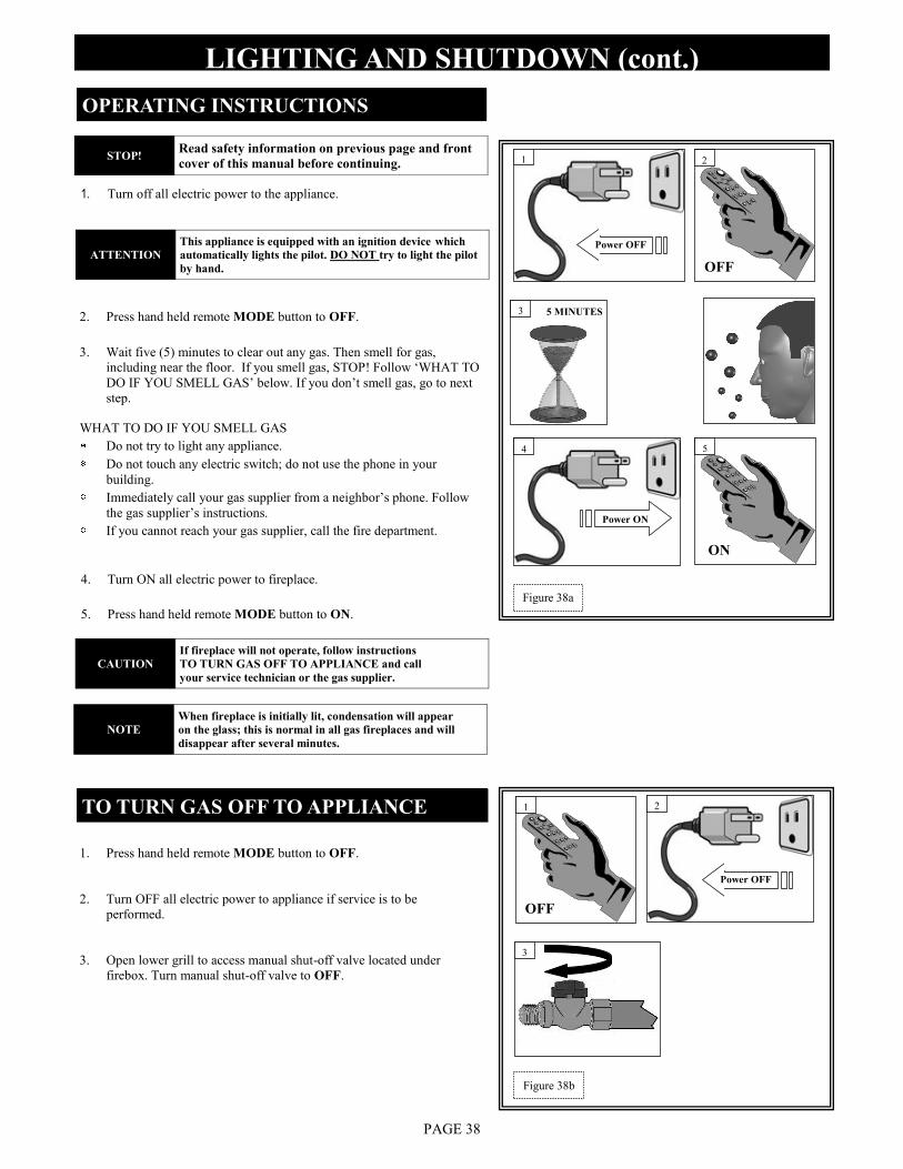
STOP! Read safety information on previous page and front
cover of this manual before continuing.
1. Turn off all electric power to the appliance.
3. Wait five (5) minutes to clear out any gas. Then smell for gas,
including near the floor. If you smell gas, STOP! Follow „WHAT TO
DO IF YOU SMELL GAS‟ below. If you don‟t smell gas, go to next
step.
OPERATING INSTRUCTIONS
5 MINUTES 2. Press hand held remote MODE button to OFF.
4. Turn ON all electric power to fireplace.
5. Press hand held remote MODE button to ON.
TO TURN GAS OFF TO APPLIANCE
1. Press hand held remote MODE button to OFF.
2. Turn OFF all electric power to appliance if service is to be
performed.
3. Open lower grill to access manual shut-off valve located under
firebox. Turn manual shut-off valve to OFF.
Power OFF
Power ON
Power OFF
OFF
OFF
ON
1
4
1
3
2
5
3
2
Figure 38b
Figure 38a
WHAT TO DO IF YOU SMELL GAS
Do not try to light any appliance.
Do not touch any electric switch; do not use the phone in your
building.
Immediately call your gas supplier from a neighbor‟s phone. Follow
the gas supplier‟s instructions.
If you cannot reach your gas supplier, call the fire department.
ATTENTION
This appliance is equipped with an ignition device which
automatically lights the pilot. DO NOT try to light the pilot
by hand.
CAUTION
If fireplace will not operate, follow instructions
TO TURN GAS OFF TO APPLIANCE and call
your service technician or the gas supplier.
NOTE
When fireplace is initially lit, condensation will appear
on the glass; this is normal in all gas fireplaces and will
disappear after several minutes.
INLET PRESSURE TEST:
1. Loosen inlet (IN) pressure tap screw (counter-clockwise).
2. Attach manometer using a 1/4” I.D. hose.
3. Light fireplace using hand held remote control. Note manometer reading.
4. Turn fireplace off using hand held remote control.
5. Disconnect hose and tighten screw (clockwise). Screw should be snug, do not over tighten.
9. Relight fireplace using hand held remote control. Reattach manometer to inlet pressure tap to verify it is completely sealed.
Manometer should read no pressure.
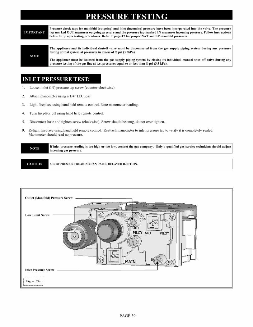
PRESSURE TESTING
PAGE 39
Outlet (Manifold) Pressure Screw
Inlet Pressure Screw
Low Limit Screw
Figure 39a
IMPORTANT
Pressure check taps for manifold (outgoing) and inlet (incoming) pressure have been incorporated into the valve. The pressure
tap marked OUT measures outgoing pressure and the pressure tap marked IN measures incoming pressure. Follow instructions
below for proper testing procedures. Refer to page 17 for proper NAT and LP manifold pressures.
NOTE
The appliance and its individual shutoff valve must be disconnected from the gas supply piping system during any pressure
testing of that system at pressures in excess of ½ psi (3.5kPa).
The appliance must be isolated from the gas supply piping system by closing its individual manual shut-off valve during any
pressure testing of the gas line at test pressures equal to or less than ½ psi (3.5 kPa).
NOTE If inlet pressure reading is too high or too low, contact the gas company. Only a qualified gas service technician should adjust
incoming gas pressure.
CAUTION A LOW PRESSURE READING CAN CAUSE DELAYED IGNITION.
PAGE 40
ERROR CODES
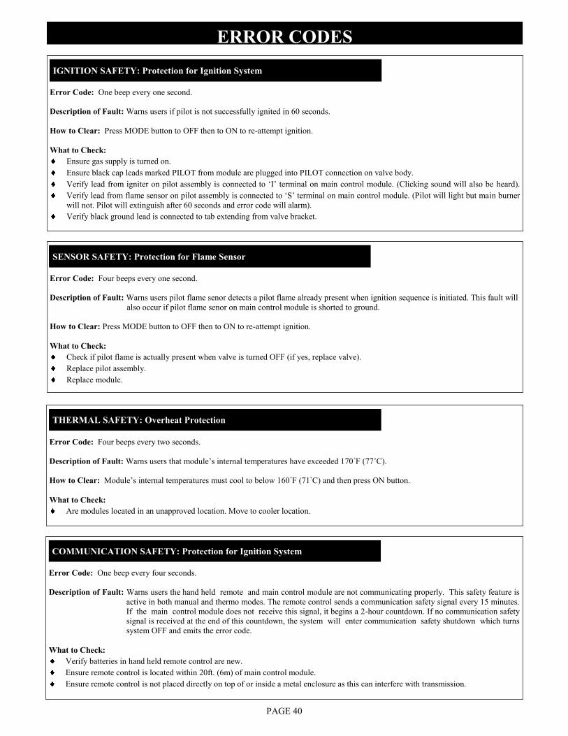
Error Code: One beep every one second.
Description of Fault: Warns users if pilot is not successfully ignited in 60 seconds.
How to Clear: Press MODE button to OFF then to ON to re-attempt ignition.
What to Check:
Ensure gas supply is turned on.
Ensure black cap leads marked PILOT from module are plugged into PILOT connection on valve body.
Verify lead from igniter on pilot assembly is connected to „I‟ terminal on main control module. (Clicking sound will also be heard).
Verify lead from flame sensor on pilot assembly is connected to „S‟ terminal on main control module. (Pilot will light but main burner
will not. Pilot will extinguish after 60 seconds and error code will alarm).
Verify black ground lead is connected to tab extending from valve bracket.
IGNITION SAFETY: Protection for Ignition System
Error Code: Four beeps every one second.
Description of Fault: Warns users pilot flame senor detects a pilot flame already present when ignition sequence is initiated. This fault will
also occur if pilot flame senor on main control module is shorted to ground.
How to Clear: Press MODE button to OFF then to ON to re-attempt ignition.
What to Check:
Check if pilot flame is actually present when valve is turned OFF (if yes, replace valve).
Replace pilot assembly.
Replace module.
SENSOR SAFETY: Protection for Flame Sensor
Error Code: Four beeps every two seconds.
Description of Fault: Warns users that module‟s internal temperatures have exceeded 170˚F (77˚C).
How to Clear: Module‟s internal temperatures must cool to below 160˚F (71˚C) and then press ON button.
What to Check:
Are modules located in an unapproved location. Move to cooler location.
Error Code: One beep every four seconds.
Description of Fault: Warns users the hand held remote and main control module are not communicating properly. This safety feature is
active in both manual and thermo modes. The remote control sends a communication safety signal every 15 minutes.
If the main control module does not receive this signal, it begins a 2-hour countdown. If no communication safety
signal is received at the end of this countdown, the system will enter communication safety shutdown which turns
system OFF and emits the error code.
What to Check:
Verify batteries in hand held remote control are new.
Ensure remote control is located within 20ft. (6m) of main control module.
Ensure remote control is not placed directly on top of or inside a metal enclosure as this can interfere with transmission.
THERMAL SAFETY: Overheat Protection
COMMUNICATION SAFETY: Protection for Ignition System
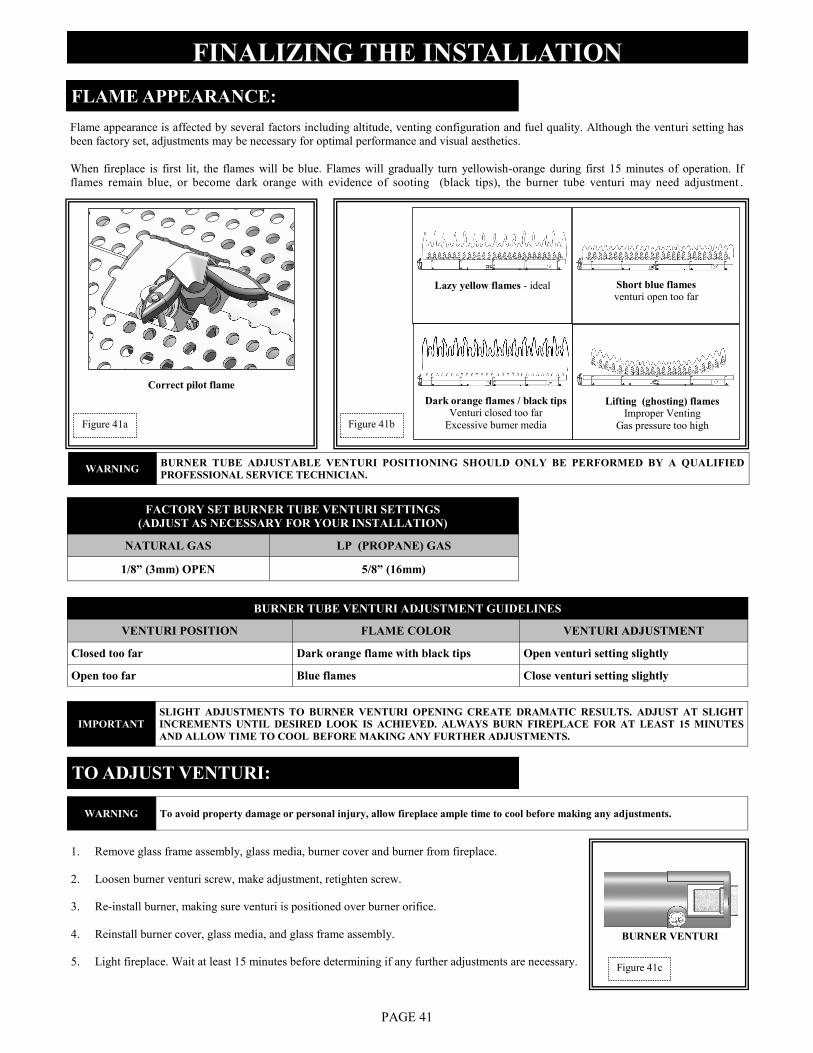
FACTORY SET BURNER TUBE VENTURI SETTINGS
(ADJUST AS NECESSARY FOR YOUR INSTALLATION)
NATURAL GAS LP (PROPANE) GAS
1/8” (3mm) OPEN 5/8” (16mm)
TO ADJUST VENTURI:
FINALIZING THE INSTALLATION FLAME APPEARANCE:
Flame appearance is affected by several factors including altitude, venting configuration and fuel quality. Although the venturi setting has
been factory set, adjustments may be necessary for optimal performance and visual aesthetics.
When fireplace is first lit, the flames will be blue. Flames will gradually turn yellowish-orange during first 15 minutes of operation. If
flames remain blue, or become dark orange with evidence of sooting (black tips), the burner tube venturi may need adjustment .
BURNER TUBE VENTURI ADJUSTMENT GUIDELINES
VENTURI POSITION FLAME COLOR VENTURI ADJUSTMENT
Closed too far Dark orange flame with black tips Open venturi setting slightly
Open too far Blue flames Close venturi setting slightly
PAGE 41
1. Remove glass frame assembly, glass media, burner cover and burner from fireplace.
2. Loosen burner venturi screw, make adjustment, retighten screw.
3. Re-install burner, making sure venturi is positioned over burner orifice.
4. Reinstall burner cover, glass media, and glass frame assembly.
5. Light fireplace. Wait at least 15 minutes before determining if any further adjustments are necessary.
BURNER VENTURI
Figure 41c
WARNING BURNER TUBE ADJUSTABLE VENTURI POSITIONING SHOULD ONLY BE PERFORMED BY A QUALIFIED
PROFESSIONAL SERVICE TECHNICIAN.
IMPORTANT
SLIGHT ADJUSTMENTS TO BURNER VENTURI OPENING CREATE DRAMATIC RESULTS. ADJUST AT SLIGHT
INCREMENTS UNTIL DESIRED LOOK IS ACHIEVED. ALWAYS BURN FIREPLACE FOR AT LEAST 15 MINUTES
AND ALLOW TIME TO COOL BEFORE MAKING ANY FURTHER ADJUSTMENTS.
WARNING To avoid property damage or personal injury, allow fireplace ample time to cool before making any adjustments.
Lazy yellow flames - ideal Short blue flames
venturi open too far
Dark orange flames / black tips Venturi closed too far
Excessive burner media
Lifting (ghosting) flames Improper Venting
Gas pressure too high
Correct pilot flame
Figure 41b Figure 41a
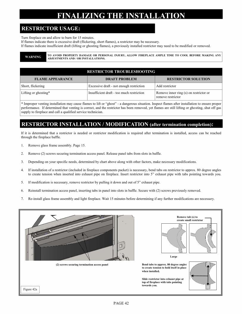
If it is determined that a restrictor is needed or restrictor modification is required after termination is installed, access can be reached
through the fireplace baffle.
1. Remove glass frame assembly. Page 15.
2. Remove (2) screws securing termination access panel. Release panel tabs from slots in baffle.
3. Depending on your specific needs, determined by chart above along with other factors, make necessary modifications.
4. If installation of a restrictor (included in fireplace components packet) is necessary, bend tabs on restrictor to approx. 80 degree angles
to create tension when inserted into exhaust pipe on fireplace. Insert restrictor into 5” exhaust pipe with tabs pointing towards you.
5. If modification is necessary, remove restrictor by pulling it down and out of 5” exhaust pipe.
6. Reinstall termination access panel, inserting tabs in panel into slots in baffle. Secure with (2) screws previously removed.
7. Re-install glass frame assembly and light fireplace. Wait 15 minutes before determining if any further modifications are necessary.
PAGE 42
FINALIZING THE INSTALLATION RESTRICTOR USAGE:
Turn fireplace on and allow to burn for 15 minutes.
If flames indicate there is excessive draft (flickering, short flames), a restrictor may be necessary.
If flames indicate insufficient draft (lifting or ghosting flames), a previously installed restrictor may need to be modified or removed.
RESTRICTOR INSTALLATION / MODIFICATION (after termination completion):
RESTRICTOR TROUBLESHOOTING
FLAME APPEARANCE DRAFT PROBLEM RESTRICTOR SOLUTION
Short, flickering Excessive draft - not enough restriction Add restrictor
Lifting or ghosting* Insufficient draft - too much restriction Remove inner ring (s) on restrictor or
remove restrictor
* Improper venting installation may cause flames to lift or “ghost” - a dangerous situation. Inspect flames after installation to ensure proper
performance. If determined that venting is correct, and the restrictor has been removed, yet flames are still lifting or ghosting, shut off gas
supply to fireplace and call a qualified service technician.
(2) screws securing termination access panel
Large
Remove tab (s) to
create small restrictor
Bend tabs to approx. 80 degree angles
to create tension to hold itself in place
when installed.
Slide restrictor into exhaust pipe at
top of fireplace with tabs pointing
towards you.
Figure 42a
WARNING TO AVOID PROPERTY DAMAGE OR PERSONAL INJURY, ALLOW FIREPLACE AMPLE TIME TO COOL BEFORE MAKING ANY
ADJUSTMENTS AND / OR INSTALLATIONS.
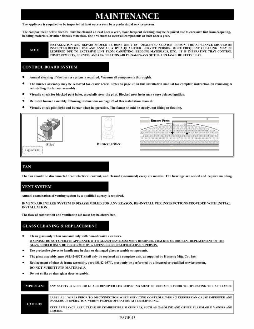
Burner Ports
Annual cleaning of the burner system is required. Vacuum all components thoroughly.
The burner assembly may be removed for easier access. Refer to page 28 in this installation manual for complete instruction on removing &
reinstalling the burner assembly.
Visually check for blocked port holes, especially near the pilot. Blocked port holes may cause delayed ignition.
Reinstall burner assembly following instructions on page 28 of this installation manual.
Visually check pilot light and burner when in operation. The flames should be steady, not lifting or floating.
The appliance is required to be inspected at least once a year by a professional service person.
The compartment below firebox must be cleaned at least once a year, more frequent cleaning may be required due to excessive lint from carpeting,
bedding materials, or other fibrous materials. Use a vacuum to clean all components at least once a year.
Burner Orifice
MAINTENANCE
CONTROL BOARD SYSTEM
PAGE 43
Pilot
Annual examination of venting system by a qualified agency is required.
IF VENT-AIR INTAKE SYSTEM IS DISASSEMBLED FOR ANY REASON, RE-INSTALL PER INSTRUCTIONS PROVIDED WITH INITIAL
INSTALLATION.
The flow of combustion and ventilation air must not be obstructed.
VENT SYSTEM
FAN
Clean glass only when cool and only with non-abrasive cleansers.
WARNING: DO NOT OPERATE APPLIANCE WITH GLASS/FRAME ASSEMBLY REMOVED, CRACKED OR BROKEN. REPLACEMENT OF THE
GLASS SHOULD ONLY BE PERFORMED BY A LICENSED OR QUALIFIED SERVICE PERSON.
Use protective gloves to handle any broken or damaged glass assembly components.
The glass assembly, part #SL42-057T, shall only be replaced as a complete unit, as supplied by Hussong Mfg. Co., Inc.
Replacement of glass & frame assembly, part #SL42-057T, must only be performed by a licensed or qualified service person.
DO NOT SUBSTITUTE MATERIALS.
Do not strike or slam glass door assembly.
GLASS CLEANING & REPLACEMENT
The fan should be disconnected from electrical current, and cleaned (vacuumed) every six months. The bearings are sealed and require no oiling.
Figure 43a
NOTE
INSTALLATION AND REPAIR SHOULD BE DONE ONLY BY QUALIFIED SERVICE PERSON. THE APPLIANCE SHOULD BE
INSPECTED BEFORE USE AND ANNUALLY BY A QUALIFIED SERVICE PERSON. MORE FREQUENT CLEANING MAY BE
REQUIRED DUE TO EXCESSIVE LINT FROM CARPETING, BEDDING MATERIALS, ETC. IT IS IMPERATIVE THAT CONTROL
COMPARTMENTS, BURNERS AND CIRCULATION AIR PASSAGEWAYS OF THE APPLIANCE BE KEPT CLEAN.
IMPORTANT ANY SAFETY SCREEN OR GUARD REMOVED FOR SERVICING MUST BE REPLACED PRIOR TO OPERATING THE APPLIANCE.
CAUTION
LABEL ALL WIRES PRIOR TO DISCONNECTION WHEN SERVICING CONTROLS. WIRING ERRORS CAN CAUSE IMPROPER AND
DANGEROUS OPERATION. VERIFY PROPER OPERATION AFTER SERVICING.
KEEP APPLIANCE AREA CLEAR OF COMBUSTIBLE MATERIALS, SUCH AS GASOLINE AND OTHER FLAMMABLE VAPORS AND
LIQUIDS.
PAGE 44
TROUBLESHOOTING
MAIN CONTROL MODULE WILL NOT LEARN TRANSMITTER
Ensure REMOTE/OFF switch on side of main control module is set to REMOTE.
Make sure batteries in both the hand held remote and backup battery pack are installed in the proper direction and are not drained.
Verify hand held remote indicates a signal is being sent. The LCD display should indicate ON or OFF depending on which button is
being pressed. The LED indicator should illuminate on wall transmitters and on/off transmitters. Buttons should be pressed and held
for 1 to 2 seconds to ensure a complete signal is sent.
Ensure 4-pin lead-set is securely connected from battery pack to main control module‟s AUX connection. If the A/C adapter is used,
check that leads from adapter are securely connected to POWER terminals on main control module.
Press and hold LEARN button on main control module for approximately 10 seconds to clear memory (you should hear a series of
beeps from the receiver), immediately press either the ON or OFF button on hand held remote (you should hear a series of beeps
indicating the transmitter code has been learned).
PILOT WILL NOT LIGHT / STAY LIT
Verify gas supply is turned on.
Verify main control module is receiving signal from hand held remote by listening for a beep from receiver when ON is pressed on
hand held remote. If you do not hear a beep, ensure main control module has learned the hand held remote. (See above).
Ensure black lead from pilot assembly igniter is securely connected to terminal labeled „I‟ and red lead from flame rectification
sensor is securely connected terminal labeled „S‟ on main control module.
Make sure black cap leads marked PILOT from main control module are securely connected to terminals labeled PILOT on valve
body.
Ensure black GROUND wire is securely connected to tab located next to ON/OFF toggle switch. A proper ground is essential to
spark igniter operation.
Make sure pilot flame is in contact with flame rectification sensor on pilot assembly. This valve is equipped with a pilot flame
adjustment screw. If pilot flame is too small it will not contact flame rectification sensor and will not complete the safety circuit.
Check continuity of pilot on valve. Remove wire connector. If there is no continuity on pin terminals, replace valve.
PILOT FLAME ALWAYS ON / WILL NOT EXTINGUISH
Ensure continuous pilot icon is not present in LCD screen. If icon is present, press PILOT button. This will de-activate the continuous
pilot feature and the icon will disappear from LCD screen.
PILOT BURNING BUT IGNITER CONTINUES TO SPARK
Check that flame sensor is fully impinged by pilot flame. If needed, adjust pilot.
Check end-to-end continuity of sensor. If sensor has continuity, replace module.
PAGE 45
MAIN FLAME WILL NOT LIGHT
Verify gas supply is turned on.
Ensure pilot flame will ignite. If not, see pilot flame troubleshooting on previous page.
Make sure white cap leads marked MAIN from module are securely connected to terminals marked MAIN on valve body.
Make certain pilot flame is in contact with flame rectification sensor on pilot assembly. This valve is equipped with a pilot flame
adjustment screw. If pilot flame is too small it will not contact flame rectification sensor and will not complete the safety circuit.
Ensure pilot flame is properly located to ignite main flame.
Does hand held remote show CP in the display? If yes, childproof is on. De-activate by pushing PROG/TIME & UP keys at same time
for more than 5 seconds.
Check continuity of main burner coil on gas valve. Remove wire connector. If there is no continuity on pin terminals, replace valve.
TROUBLESHOOTING
FLAME HEIGHT ADJUSTMENT NOT WORKING / WORKS BACKWARDS
ROOM TEMP. DISPLAYED ON HANDHELD REMOTE NOT CORRECT
Ensure transmitter was not recently stored in a different location (air-conditioned, heated) from that in which the hand held remote was
tested. It may take up to 3 hours for the temperature inside a packaged transmitter, and several minutes for an unpackaged transmitter
to equalize with room temperature.
FIREPLACE WILL NOT RESPOND IN “THERMO” MODE
Ensure hand held remote is within 20ft. (6.096m) operational range.
Make sure an ON or OFF command was not last sent from another transmitter. These commands will override thermal commands from
the handheld remote control. To return system to THERMO mode, press either ON or OFF on hand held remote, then press MODE
button to put system in THERMO mode. Press and hold SET button to change set temperature.
Verify set temperature on hand held remote is at least 2˚F (1˚C) above or below room temperature. The system will not react to
temperatures within 2˚F (1˚C) of set temperature.
Ensure „+‟ (white dotted wire) and „—‟ (black wire) leads from battery pack or module are securely connected to „+‟ (white dotted
wire) and „—‟ (black wire) leads from main control module (‟+‟ to „+‟, „—‟ to „—‟).
Check functionality with all transmitters to determine if there is an issue with the main control system or an individual transmitter. If
the issue is with an individual transmitter, make sure batteries in hand held remote and backup battery pack are installed properly and
are not drained.
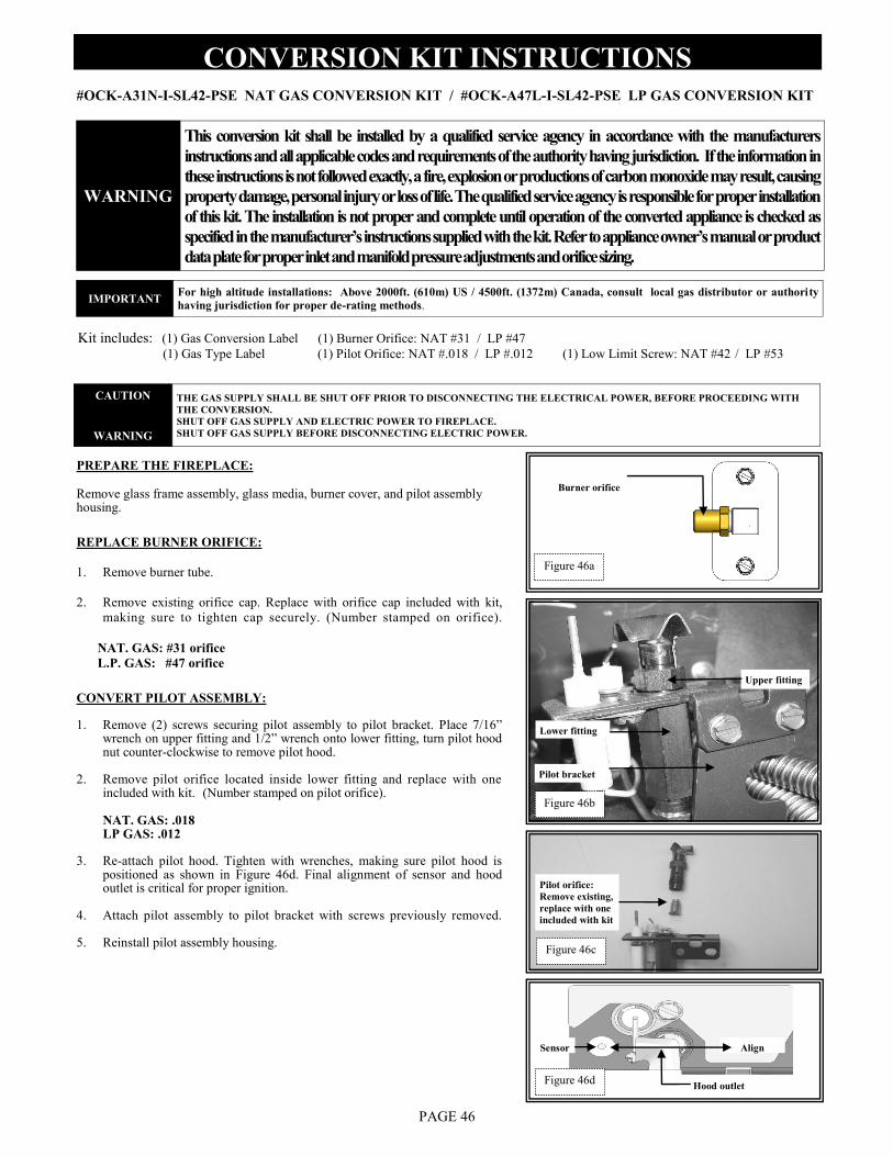
CONVERSION KIT INSTRUCTIONS
#OCK-A31N-I-SL42-PSE NAT GAS CONVERSION KIT / #OCK-A47L-I-SL42-PSE LP GAS CONVERSION KIT
Kit includes: (1) Gas Conversion Label (1) Burner Orifice: NAT #31 / LP #47
(1) Gas Type Label (1) Pilot Orifice: NAT #.018 / LP #.012 (1) Low Limit Screw: NAT #42 / LP #53
PREPARE THE FIREPLACE:
Remove glass frame assembly, glass media, burner cover, and pilot assembly housing.
REPLACE BURNER ORIFICE:
1. Remove burner tube.
2. Remove existing orifice cap. Replace with orifice cap included with kit,
making sure to tighten cap securely. (Number stamped on orifice).
NAT. GAS: #31 orifice
L.P. GAS: #47 orifice
Burner orifice
CONVERT PILOT ASSEMBLY: 1. Remove (2) screws securing pilot assembly to pilot bracket. Place 7/16”
wrench on upper fitting and 1/2” wrench onto lower fitting, turn pilot hood nut counter-clockwise to remove pilot hood.
2. Remove pilot orifice located inside lower fitting and replace with one included with kit. (Number stamped on pilot orifice). NAT. GAS: .018 LP GAS: .012
3. Re-attach pilot hood. Tighten with wrenches, making sure pilot hood is positioned as shown in Figure 46d. Final alignment of sensor and hood outlet is critical for proper ignition.
4. Attach pilot assembly to pilot bracket with screws previously removed.
5. Reinstall pilot assembly housing.
Upper fitting
Lower fitting
Pilot orifice:
Remove existing,
replace with one
included with kit
Pilot bracket
Hood outlet
Sensor Align
Figure 46a
Figure 46d
Figure 46b
WARNING
This conversion kit shall be installed by a qualified service agency in accordance with the manufacturers
instructions and all applicable codes and requirements of the authority having jurisdiction. If the information in
these instructions is not followed exactly, a fire, explosion or productions of carbon monoxide may result, causing
property damage, personal injury or loss of life. The qualified service agency is responsible for proper installation
of this kit. The installation is not proper and complete until operation of the converted appliance is checked as
specified in the manufacturer‟s instructions supplied with the kit. Refer to appliance owner‟s manual or product
data plate for proper inlet and manifold pressure adjustments and orifice sizing.
IMPORTANT For high altitude installations: Above 2000ft. (610m) US / 4500ft. (1372m) Canada, consult local gas distributor or authority
having jurisdiction for proper de-rating methods.
CAUTION
WARNING
THE GAS SUPPLY SHALL BE SHUT OFF PRIOR TO DISCONNECTING THE ELECTRICAL POWER, BEFORE PROCEEDING WITH
THE CONVERSION.
SHUT OFF GAS SUPPLY AND ELECTRIC POWER TO FIREPLACE.
SHUT OFF GAS SUPPLY BEFORE DISCONNECTING ELECTRIC POWER.
Figure 46c
PAGE 46
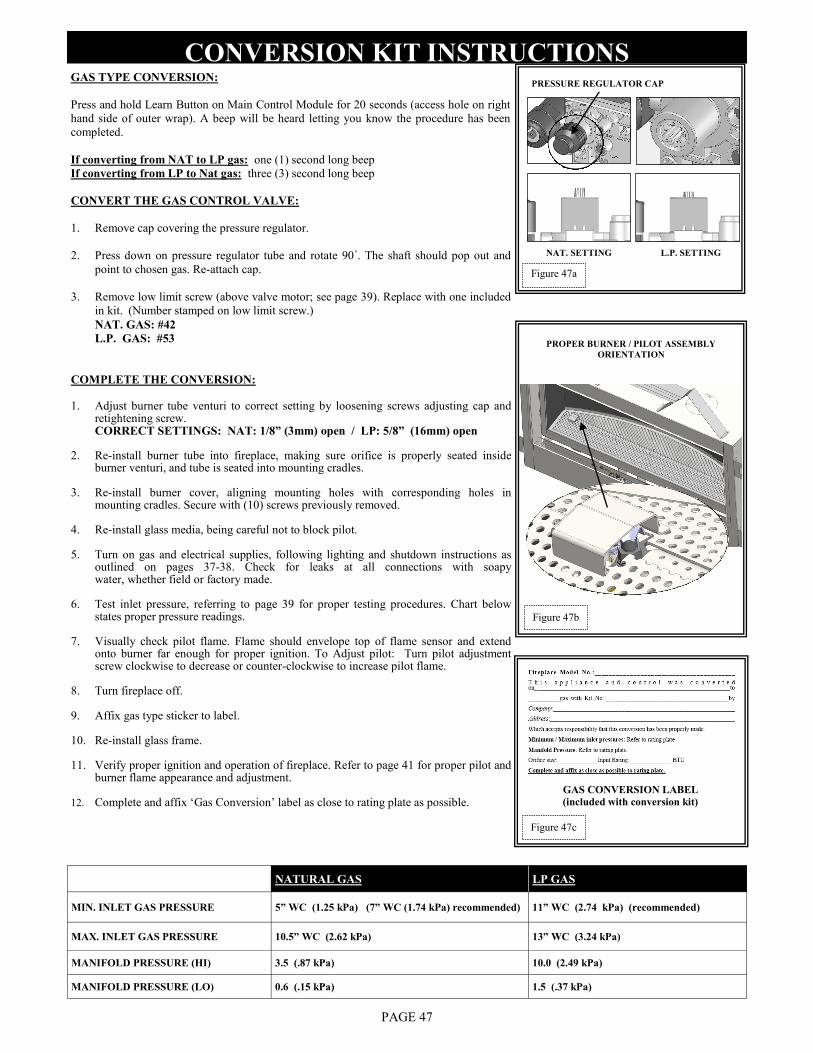
GAS TYPE CONVERSION:
Press and hold Learn Button on Main Control Module for 20 seconds (access hole on right
hand side of outer wrap). A beep will be heard letting you know the procedure has been
completed.
If converting from NAT to LP gas: one (1) second long beep
If converting from LP to Nat gas: three (3) second long beep
CONVERT THE GAS CONTROL VALVE:
1. Remove cap covering the pressure regulator.
2. Press down on pressure regulator tube and rotate 90˚. The shaft should pop out and
point to chosen gas. Re-attach cap.
3. Remove low limit screw (above valve motor; see page 39). Replace with one included
in kit. (Number stamped on low limit screw.)
NAT. GAS: #42
L.P. GAS: #53
L.P. SETTING
PRESSURE REGULATOR CAP
NAT. SETTING
COMPLETE THE CONVERSION:
1. Adjust burner tube venturi to correct setting by loosening screws adjusting cap and
retightening screw. CORRECT SETTINGS: NAT: 1/8” (3mm) open / LP: 5/8” (16mm) open
2. Re-install burner tube into fireplace, making sure orifice is properly seated inside burner venturi, and tube is seated into mounting cradles.
3. Re-install burner cover, aligning mounting holes with corresponding holes in mounting cradles. Secure with (10) screws previously removed.
4. Re-install glass media, being careful not to block pilot.
5. Turn on gas and electrical supplies, following lighting and shutdown instructions as outlined on pages 37-38. Check for leaks at all connections with soapy water, whether field or factory made.
6. Test inlet pressure, referring to page 39 for proper testing procedures. Chart below states proper pressure readings.
7. Visually check pilot flame. Flame should envelope top of flame sensor and extend onto burner far enough for proper ignition. To Adjust pilot: Turn pilot adjustment screw clockwise to decrease or counter-clockwise to increase pilot flame.
8. Turn fireplace off.
9. Affix gas type sticker to label.
10. Re-install glass frame.
11. Verify proper ignition and operation of fireplace. Refer to page 41 for proper pilot and burner flame appearance and adjustment.
12. Complete and affix „Gas Conversion‟ label as close to rating plate as possible.
CONVERSION KIT INSTRUCTIONS
PAGE 47
Figure 47a
GAS CONVERSION LABEL
(included with conversion kit)
Figure 47c
Figure 47b
PROPER BURNER / PILOT ASSEMBLY
ORIENTATION
NATURAL GAS LP GAS
MIN. INLET GAS PRESSURE 5” WC (1.25 kPa) (7” WC (1.74 kPa) recommended) 11” WC (2.74 kPa) (recommended)
MAX. INLET GAS PRESSURE 10.5” WC (2.62 kPa) 13” WC (3.24 kPa)
MANIFOLD PRESSURE (HI) 3.5 (.87 kPa) 10.0 (2.49 kPa)
MANIFOLD PRESSURE (LO) 0.6 (.15 kPa) 1.5 (.37 kPa)
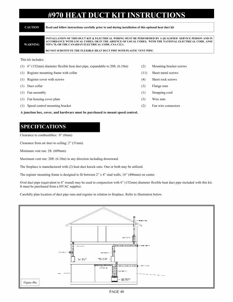
#970 HEAT DUCT KIT INSTRUCTIONS
PAGE 48
Clearance to combustibles: 0” (0mm)
Clearance from air duct to ceiling: 2” (51mm)
Minimum vent run: 2ft. (609mm)
Maximum vent run: 20ft. (6.10m) in any direction including downward.
The fireplace is manufactured with (2) heat duct knock-outs. One or both may be utilized.
The register mounting frame is designed to fit between 2” x 4” stud walls, 16” (406mm) on center.
Oval duct pipe (equivalent to 6” round) may be used in conjunction with 6” (152mm) diameter flexible heat duct pipe included with this kit.
It must be purchased from a HVAC supplier.
Carefully plan location of duct pipe runs and register in relation to fireplace. Refer to illustration below.
This kit includes:
(1) 6” (152mm) diameter flexible heat duct pipe, expandable to 20ft. (6.10m) (2) Mounting bracket screws
(1) Register mounting frame with collar (11) Sheet metal screws
(1) Register cover with screws (4) Sheet rock screws
(1) Duct collar (3) Flange nuts
(1) Fan assembly (1) Strapping cord
(1) Fan housing cover plate (3) Wire nuts
(1) Speed control mounting bracket (2) Fan wire connectors
A junction box, cover, and hardware must be purchased to mount speed control.
SPECIFICATIONS
CAUTION Read and follow instructions carefully prior to and during installation of this optional heat duct kit
WARNING
INSTALLATION OF THIS DUCT KIT & ELECTRICAL WIRING MUST BE PERFORMED BY A QUALIFIED SERVICE PERSON AND IN
ACCORDANCE WITH LOCAL CODES, OR IN THE ABSENCE OF LOCAL CODES, WITH THE NATIONAL ELECTRICAL CODE, ANSI/
NFPA 70, OR THE CANADIAN ELECTRICAL CODE, CSA C22.1.
DO NOT SUBSTITUTE THE FLEXIBLE HEAT DUCT PIPE WITH PLASTIC VENT PIPE!
Figure 48a
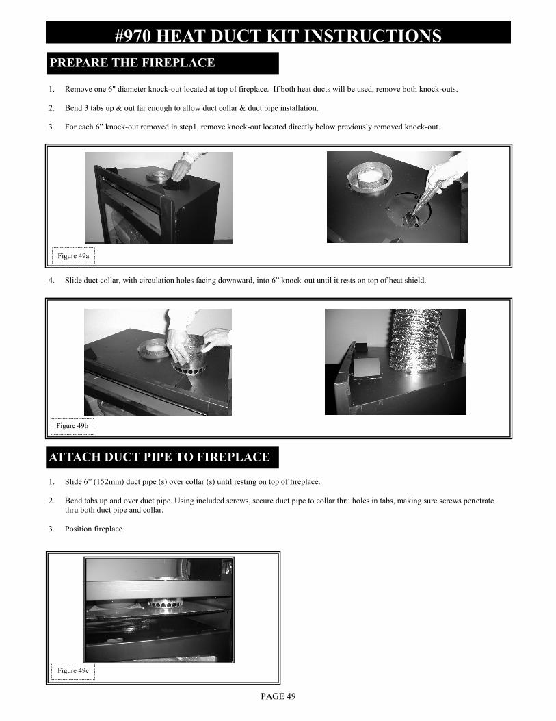
#970 HEAT DUCT KIT INSTRUCTIONS
PAGE 49
1. Remove one 6" diameter knock-out located at top of fireplace. If both heat ducts will be used, remove both knock-outs.
2. Bend 3 tabs up & out far enough to allow duct collar & duct pipe installation.
3. For each 6” knock-out removed in step1, remove knock-out located directly below previously removed knock-out.
4. Slide duct collar, with circulation holes facing downward, into 6” knock-out until it rests on top of heat shield.
1. Slide 6” (152mm) duct pipe (s) over collar (s) until resting on top of fireplace.
2. Bend tabs up and over duct pipe. Using included screws, secure duct pipe to collar thru holes in tabs, making sure screws penetrate
thru both duct pipe and collar.
3. Position fireplace.
ATTACH DUCT PIPE TO FIREPLACE
PREPARE THE FIREPLACE
Figure 49a
Figure 49c
Figure 49b
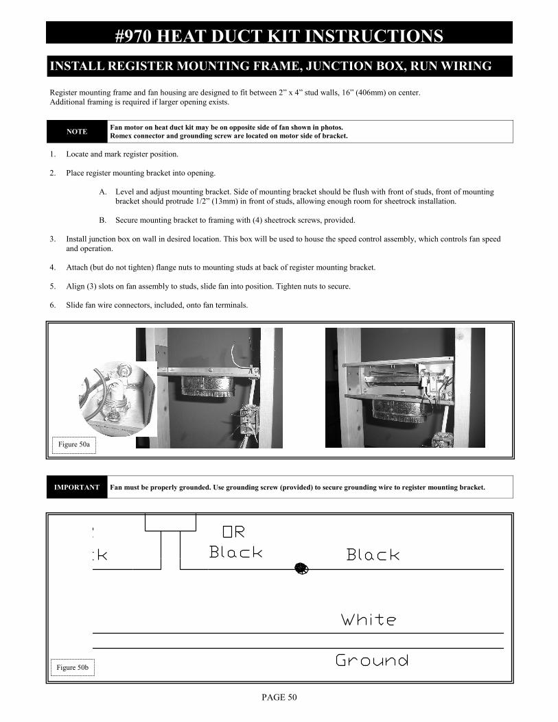
#970 HEAT DUCT KIT INSTRUCTIONS
PAGE 50
Figure 50a
Register mounting frame and fan housing are designed to fit between 2” x 4” stud walls, 16” (406mm) on center.
Additional framing is required if larger opening exists.
1. Locate and mark register position.
2. Place register mounting bracket into opening.
A. Level and adjust mounting bracket. Side of mounting bracket should be flush with front of studs, front of mounting
bracket should protrude 1/2” (13mm) in front of studs, allowing enough room for sheetrock installation.
B. Secure mounting bracket to framing with (4) sheetrock screws, provided.
3. Install junction box on wall in desired location. This box will be used to house the speed control assembly, which controls fan speed
and operation.
4. Attach (but do not tighten) flange nuts to mounting studs at back of register mounting bracket.
5. Align (3) slots on fan assembly to studs, slide fan into position. Tighten nuts to secure.
6. Slide fan wire connectors, included, onto fan terminals.
INSTALL REGISTER MOUNTING FRAME, JUNCTION BOX, RUN WIRING
NOTE Fan motor on heat duct kit may be on opposite side of fan shown in photos.
Romex connector and grounding screw are located on motor side of bracket.
IMPORTANT Fan must be properly grounded. Use grounding screw (provided) to secure grounding wire to register mounting bracket.
Figure 50b
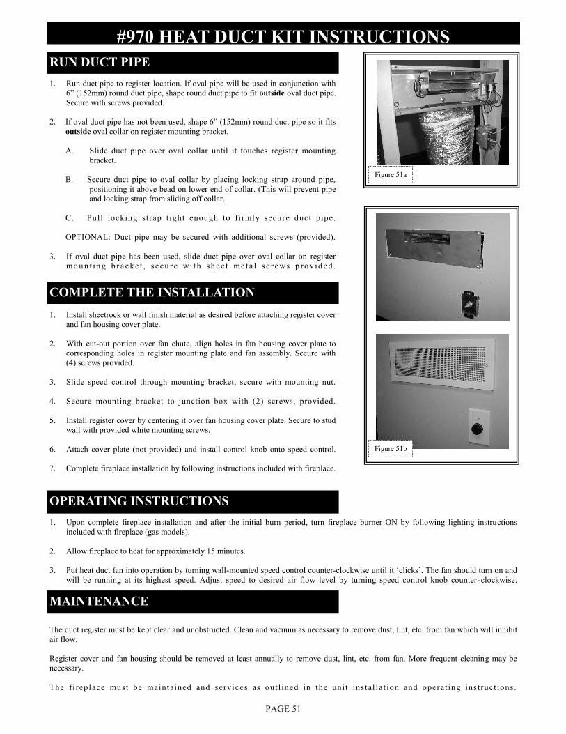
#970 HEAT DUCT KIT INSTRUCTIONS
PAGE 51
RUN DUCT PIPE
1. Run duct pipe to register location. If oval pipe will be used in conjunction with
6” (152mm) round duct pipe, shape round duct pipe to fit outside oval duct pipe.
Secure with screws provided.
2. If oval duct pipe has not been used, shape 6” (152mm) round duct pipe so it fits
outside oval collar on register mounting bracket.
A. Slide duct pipe over oval collar until it touches register mounting
bracket.
B. Secure duct pipe to oval collar by placing locking strap around pipe,
positioning it above bead on lower end of collar. (This will prevent pipe
and locking strap from sliding off collar .
C. Pull locking strap t ight enough to firmly secure duct pipe.
OPTIONAL: Duct pipe may be secured with additional screws (provided).
3. If oval duct pipe has been used, slide duct pipe over oval collar on register
mo u n t in g b r a c k e t , s e cu r e wi t h sh e e t me t a l s c r e ws p ro v id e d .
COMPLETE THE INSTALLATION
1. Install sheetrock or wall finish material as desired before attaching register cover
and fan housing cover plate.
2. With cut-out portion over fan chute, align holes in fan housing cover plate to
corresponding holes in register mounting plate and fan assembly. Secure with
(4) screws provided.
3. Slide speed control through mounting bracket, secure with mounting nut.
4. Secure mounting bracket to junction box with (2) screws, provided.
5. Install register cover by centering it over fan housing cover plate. Secure to stud
wall with provided white mounting screws.
6. Attach cover plate (not provided) and install control knob onto speed control.
7. Complete fireplace installation by following instructions included with fireplace.
OPERATING INSTRUCTIONS
1. Upon complete fireplace installation and after the initial burn period, turn fireplace burner ON by following lighting instructions
included with fireplace (gas models).
2. Allow fireplace to heat for approximately 15 minutes.
3. Put heat duct fan into operation by turning wall-mounted speed control counter-clockwise until it „clicks‟. The fan should turn on and
will be running at its highest speed. Adjust speed to desired air flow level by turning speed control knob counter -clockwise.
The duct register must be kept clear and unobstructed. Clean and vacuum as necessary to remove dust, lint, etc. from fan which will inhibit
air flow.
Register cover and fan housing should be removed at least annually to remove dust, lint, etc. from fan. More frequent cleaning may be
necessary.
The fi rep lace must be maintained and services as ou tl ined in the unit instal la t ion and operat ing ins truct ions.
MAINTENANCE
Figure 51b
Figure 51a
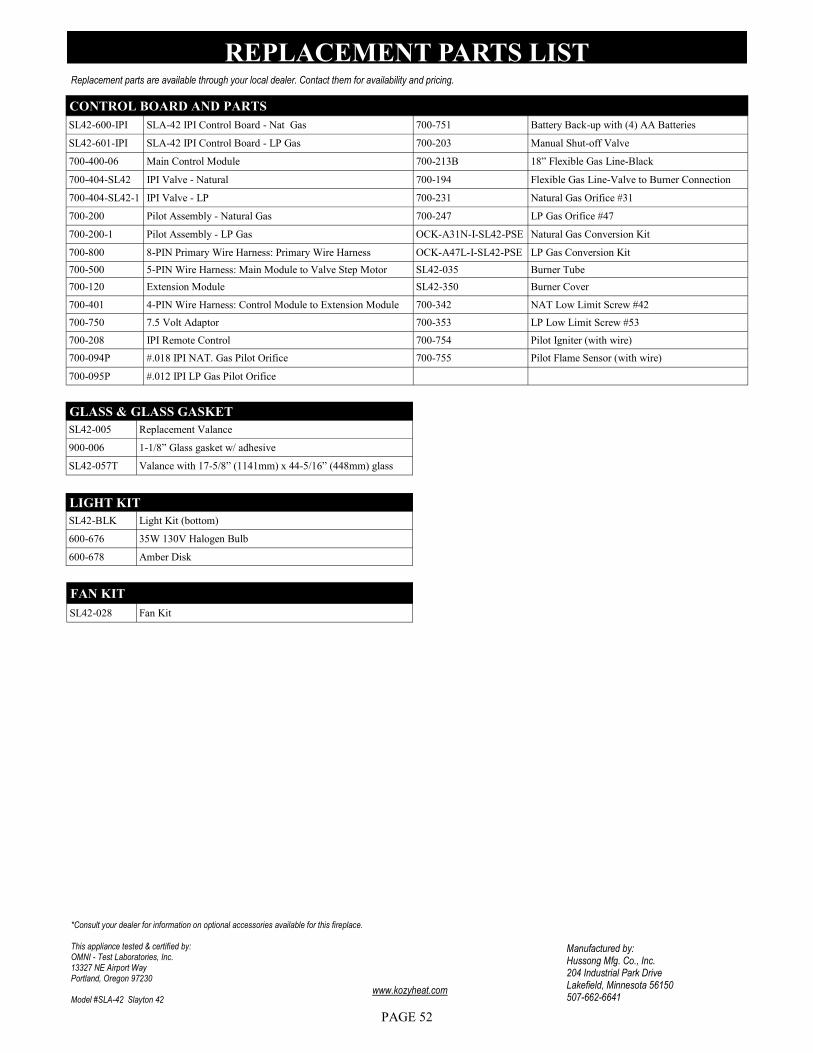
Replacement parts are available through your local dealer. Contact them for availability and pricing.
CONTROL BOARD AND PARTS
SL42-600-IPI SLA-42 IPI Control Board - Nat Gas 700-751 Battery Back-up with (4) AA Batteries
SL42-601-IPI SLA-42 IPI Control Board - LP Gas 700-203 Manual Shut-off Valve
700-400-06 Main Control Module 700-213B 18” Flexible Gas Line-Black
700-404-SL42 IPI Valve - Natural 700-194 Flexible Gas Line-Valve to Burner Connection
700-404-SL42-1 IPI Valve - LP 700-231 Natural Gas Orifice #31
700-200 Pilot Assembly - Natural Gas 700-247 LP Gas Orifice #47
700-200-1 Pilot Assembly - LP Gas OCK-A31N-I-SL42-PSE Natural Gas Conversion Kit
700-800 8-PIN Primary Wire Harness: Primary Wire Harness OCK-A47L-I-SL42-PSE LP Gas Conversion Kit
700-500 5-PIN Wire Harness: Main Module to Valve Step Motor SL42-035 Burner Tube
700-120 Extension Module SL42-350 Burner Cover
700-401 4-PIN Wire Harness: Control Module to Extension Module 700-342 NAT Low Limit Screw #42
700-750 7.5 Volt Adaptor 700-353 LP Low Limit Screw #53
700-208 IPI Remote Control 700-754 Pilot Igniter (with wire)
700-094P #.018 IPI NAT. Gas Pilot Orifice 700-755 Pilot Flame Sensor (with wire)
700-095P #.012 IPI LP Gas Pilot Orifice
Manufactured by: Hussong Mfg. Co., Inc. 204 Industrial Park Drive Lakefield, Minnesota 56150 507-662-6641
www.kozyheat.com
REPLACEMENT PARTS LIST
GLASS & GLASS GASKET
SL42-005 Replacement Valance
900-006 1-1/8” Glass gasket w/ adhesive
SL42-057T Valance with 17-5/8” (1141mm) x 44-5/16” (448mm) glass
LIGHT KIT
SL42-BLK Light Kit (bottom)
600-676 35W 130V Halogen Bulb
600-678 Amber Disk
*Consult your dealer for information on optional accessories available for this fireplace. This appliance tested & certified by: OMNI - Test Laboratories, Inc. 13327 NE Airport Way Portland, Oregon 97230 Model #SLA-42 Slayton 42
PAGE 52
FAN KIT
SL42-028 Fan Kit
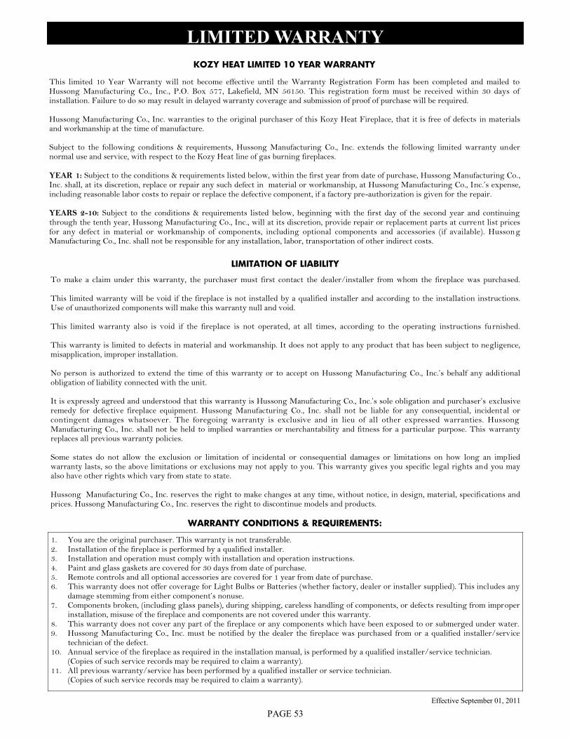
PAGE 53
LIMITED WARRANTY
WARRANTY CONDITIONS & REQUIREMENTS:
1. You are the original purchaser. This warranty is not transferable. 2. Installation of the fireplace is performed by a qualified installer. 3. Installation and operation must comply with installation and operation instructions. 4. Paint and glass gaskets are covered for 30 days from date of purchase. 5. Remote controls and all optional accessories are covered for 1 year from date of purchase. 6. This warranty does not offer coverage for Light Bulbs or Batteries (whether factory, dealer or installer supplied). This includes any
damage stemming from either component’s nonuse. 7. Components broken, (including glass panels), during shipping, careless handling of components, or defects resulting from improper
installation, misuse of the fireplace and components are not covered under this warranty. 8. This warranty does not cover any part of the fireplace or any components which have been exposed to or submerged under water. 9. Hussong Manufacturing Co., Inc. must be notified by the dealer the fireplace was purchased from or a qualified installer/service
technician of the defect. 10. Annual service of the fireplace as required in the installation manual, is performed by a qualified installer/service technician.
(Copies of such service records may be required to claim a warranty). 11. All previous warranty/service has been performed by a qualified installer or service technician.
(Copies of such service records may be required to claim a warranty).
KOZY HEAT LIMITED 10 YEAR WARRANTY
This limited 10 Year Warranty will not become effective until the Warranty Registration Form has been completed and mailed to Hussong Manufacturing Co., Inc., P.O. Box 577, Lakefield, MN 56150. This registration form must be received within 30 days of installation. Failure to do so may result in delayed warranty coverage and submission of proof of purchase will be required. Hussong Manufacturing Co., Inc. warranties to the original purchaser of this Kozy Heat Fireplace, that it is free of defects in materials and workmanship at the time of manufacture. Subject to the following conditions & requirements, Hussong Manufacturing Co., Inc. extends the following limited warranty under normal use and service, with respect to the Kozy Heat line of gas burning fireplaces. YEAR 1: Subject to the conditions & requirements listed below, within the first year from date of purchase, Hussong Manufacturing Co., Inc. shall, at its discretion, replace or repair any such defect in material or workmanship, at Hussong Manufacturing Co., Inc.’s expense, including reasonable labor costs to repair or replace the defective component, if a factory pre-authorization is given for the repair. YEARS 2-10: Subject to the conditions & requirements listed below, beginning with the first day of the second year and continuing through the tenth year, Hussong Manufacturing Co., Inc., will at its discretion, provide repair or replacement parts at current list prices for any defect in material or workmanship of components, including optional components and accessories (if available). Hussong Manufacturing Co., Inc. shall not be responsible for any installation, labor, transportation of other indirect costs.
LIMITATION OF LIABILITY
To make a claim under this warranty, the purchaser must first contact the dealer/installer from whom the fireplace was purchased. This limited warranty will be void if the fireplace is not installed by a qualified installer and according to the installation instructions. Use of unauthorized components will make this warranty null and void. This limited warranty also is void if the fireplace is not operated, at all times, according to the operating instructions furnished. This warranty is limited to defects in material and workmanship. It does not apply to any product that has been subject to negligence, misapplication, improper installation. No person is authorized to extend the time of this warranty or to accept on Hussong Manufacturing Co., Inc.’s behalf any additional obligation of liability connected with the unit. It is expressly agreed and understood that this warranty is Hussong Manufacturing Co., Inc.’s sole obligation and purchaser’s exclusive remedy for defective fireplace equipment. Hussong Manufacturing Co., Inc. shall not be liable for any consequential, incidental or contingent damages whatsoever. The foregoing warranty is exclusive and in lieu of all other expressed warranties. Hussong Manufacturing Co., Inc. shall not be held to implied warranties or merchantability and fitness for a particular purpose. This warranty replaces all previous warranty policies. Some states do not allow the exclusion or limitation of incidental or consequential damages or limitations on how long an implied warranty lasts, so the above limitations or exclusions may not apply to you. This warranty gives you specific legal rights and you may also have other rights which vary from state to state. Hussong Manufacturing Co., Inc. reserves the right to make changes at any time, without notice, in design, material, specifications and prices. Hussong Manufacturing Co., Inc. reserves the right to discontinue models and products.
Effective September 01, 2011
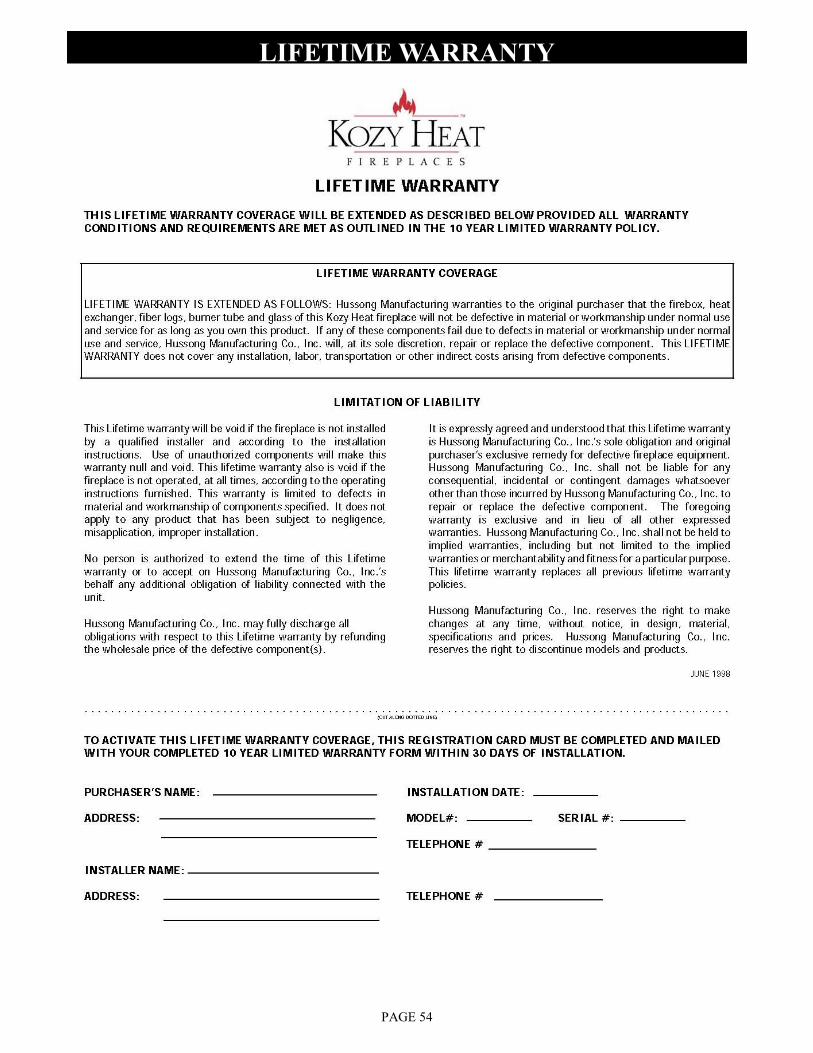
PAGE 54
LIFETIME WARRANTY