Embed Size (px)
Citation preview

OWNER’S MANUAL
VF53ASVF63AS-R PORTABLEFIRE PUMPNo.003-12076-1
5-4, Azusawa 3-Chome, Itabashi-KuTokyo 174-0051, JapanPhone: +81-3-3966-3137
VF53ASVF63AS-R PORTABLEFIRE PUMPNo.003-12076-1
OWNER’S MANUAL
OWNER’S M
ANUAL
VF53AS / VF63AS-R N
o.003-12076-1
⑩ _VF53AS

Copyright@2020 Tohatsu Corporation. All rights reserved. No part of this manual may be reported or transmitted in any from or by any means without the express written permission of Tohatsu Corporation.

APPLICATIONS OF THIS FIRE PUMP
USAGE TOHATSU portable fire pumps”VF53AS and VF63AS-R” are manufactured for use in firefighting operations.
The portable fire pumps are intended only for firefighting activities in collaboration with general public fire extinguishing equipment.
Using it for other applications is regarded as being used for improper purposes.
The manufacturer of the fire pump bears no responsibility for any damages that may result from modification of the fire pump without prior permission from the manufacture, improper use of the fire pump, or use of the fire pump for applications other than those stated above.
Note that use the fire pump for applications other than those stated above can result in personal injury or damage to the equipment.
Using the fire pump within the range of intended uses implies that the user should follow the instructions provided by the manufacturer relevant to operation, servicing and maintenance.

Intended people
All persons who operate, service or maintain the fire pump must read and understand the following items:
Owner’s manual Safety-related instructions on the pump and the other parts such as a battery. The other owner’s manuals, such as a battery charger.
The portable fire pump should be operated by only persons who received training as operators of fire engines along with each country’s (region’s) regulations. The range of personal responsibility and supervision must be strictly defined by the user.
If a person does not have adequate professional knowledge which is required for his/her assignment, he/she must undergo relevant training or receive appropriate instructions from an individual who is actually knowledgeable in operation of the fire pump.
A person who does not have enough knowledge is not permitted to operate the fire pump.
When using the fire pump, conditions under which an explosion may occur are not considered.
Keep the manual in a safe place for further reference. Operators of the fire pump must always refer to all the relevant manuals in order to avoid errors, personal injuries and equipment damages when operating the portable fire pump, and to maintain faultless operation. Place owner’s manual so that operators can refer to it where they operate the fire pump.
CAUTION

INTRODUCTION Thank you for purchasing the TOHATSU Fire Pump. This fire pump has passed a range of quality assurance standards.
Owner’s manual
The portable fire pump complies with relevant laws and regulations. The manual includes descriptions for operation and maintenance. Before using the fire pump, be sure to read and understand the manual thoroughly.
Engine operation
The manual also includes descriptions for operation and maintenance of the engine.
The manual is an important item that goes with your portable fire pump. The manual should accompany the fire pump if sold to another person.
NOTE

Before using the fire pump, write down the serial number in the following boxes. It will be useful in the case of asking about servicing, repairs and genuine parts.
Serial Number (Identification Number)
The pump serial (identification) number is marked on the adapter discharge valve.

GENERAL SAFETY INFORMATION
Overview Before operating the TOHATSU fire pump thoroughly read the manual to understand the proper operating procedures including “DANGER”, “WARNING”, “CAUTION” and “NOTE”. These notices are designed to bring attention to very important information necessary to ensure safe, trouble free operation.
Warning sign Meaning
This sign is used for safety-related instructions in this manual. Be sure to follow all safety-related instructions, otherwise personal injury may occur.
Signal words
Failure to observe will result in severe personal injury or death.
Failure to observe could result in severe personal injury or death.
Failure to observe could result in personal injury or property damage.
The instruction provides special information to facilitate the use or maintenance of the pump or to clarify important points. For attaching position of the warning label, refer to the contents “3. LABELS”. Warning labels should be read clearly at any time. If the display of the warning label may become difficult to be read, it was almost come off, you must replace paste immediately.
Safety-related instructions and warning signs
Read and follow the safety-related instructions described in the manual and all warning signs on the portable fire pump thoroughly. Always keep the warning signs in a legible condition. If any warning sign becomes illegible or detached, replace it immediately.
CAUTION
DANGER

Transporting the portable fire pump
Retractable handle is folding type. Do not put a hand or finger between top of th e retractable handle and bracket. When transporting the portable fire pump, assign one person per handle. Also, transporting the portable fire pump, it should be transported holding the handle firmly. There is a risk of injury to the leg by fall.
Durability of protection When you purchase a new pump, it is placed in a packing box and protected.
Storage of pump after transportation Keep the pump away from high humidity, and place it on a horizontal plane.
Disposal of packing box
Dispose the packing box by following the environmental laws.
Noise emission
Wear proper hearing protection during operation.
Exhaust gas
Fatal hazard from carbon monoxide (CO) poisoning
Exhaust gas emitted from the engine contains carbon monoxide (CO) etc. that may seriously affect human health. Do not operate the engine in a room, car, warehouse, tunnel or other closed locations that have poor ventilation.
CAUTION
CAUTION

Safety devices Before operating the portable fire pump, be sure to check that all the safety devices have been installed in the appropriate positions. Before removing the safety devices, turn the main switch off.
After protection devices (such as muffler guard) have been disassembled as part of servicing and maintenance work, install them back as soon as possible to their original positions, and make sure that they are in safe secure condition.
Check the portable fire pump visually and functionally on a regular basis.
If you find any faulty devices or equipment, remove it immediately, and repair or replace it, if necessary. Failure to do so may cause an accident. After it has been repaired or replaced, make sure that it functions correctly.
Protective clothing and Protective equipment
During fire extinguishing training or regular firefighting services, wear normal protective clothing and equipment to protect your body.
Fire protective closing Fireproof helmet Fireproof protective gloves
Fireproof protective boots

Service and Maintenance
Servicing and maintenance of the fire pump must be carried out by o n l y th e persons who have professional knowledge, who are familiar with the device, and who understand laws and regulations regarding safety and accident prevention.
Before starting maintenance work, turn the main switch off to stop the engine.
Disconnect the negative terminal of the battery.
Before starting maintenance work, securely place the portable fire pump on the ground.
Do not touch the exhaust pipe, the muffler and the other engine parts until these parts will be cold enough. These parts could be very hot and will cause severe burns.
Electrical equipment Only expert electricians or trained staff members should handle electrical equipment.
When removing the battery cable from the electrical equipment, always disconnect the negative (-) cable first.
When connecting the cable to the battery, be sure to connect the positive (+) cable first. After that, connect the negative (-) cable.
Do not place any metal on the top of or around the battery. Doing so many causes a short circuit.
Use a fuse with the same specifications as the original one when replacing it. Using a fuse that has a greater capacity than the rated value may damage the equipment.
While the engine is running, do not touch the high voltage ignition wire attached to spark plug. This wire carries very high voltage which will cause injury and bodily harm.
Check the electrical equipment of the fire pump on a regular basis.

Battery Follow any safety-related instructions shown on the battery. The battery can generate flammable hydrogen gas that may cause an explosion. Do not charge the battery in closed location. Do not smoke around the battery. The battery electrolyte is caustic and may cause personal Injuries.
Always wear protective clothing. Always wear protective gloves. Always wear protective glasses. Do not tilt the battery. Doing so may cause the battery electrolyte to leak out from the vent hole.
Handling of fuel Exercise care when handling fuel. Failure to do so may cause fire. Do not bring any flames near fuel. Stop the engine before refilling fuel. Do not smoke while refilling fuel. Do not refill fuel in an enclosed room to avoid an explosion by fuel fumes. If fuel spills, wipe it with a cloth or other material, and dispose it according to relevant laws and regulations.
Crude oil, gasoline, diesel fuel and other petroleum products can expose you to chemicals including toluene and benzene, which are known to the State of California to cause cancer and birth defects or other reproductive harm. These exposures can occur in and around oil fields, refineries, chemical plants, transport and storage operations such as pipelines, marine terminals, tank trucks and other facilities and equipment. For more information go to: www.P65Warnings.ca.gov/petroleum.
Disposal
Dispose the disused batteries according to relevant laws and regulations.

Genuine parts When replacing parts for servicing and maintenance of portable fire pumps, be sure to use only Tohatsu genuine parts.
If genuine Tohatsu parts and accessories are not used, it may adversely affect the functioning and safety of the fire pump. Use genuine Tohatsu parts only.
Tohatsu bears no responsibility for any personal injuries or equipment damage that may result from use of parts or accessories obtained from outside sources.
Environmental protection measures
Dispose of oil, fuel, batteries, etc. according to relevant environmental laws. Do not dump waste into the ground, water, or sewerage. Store the fuel only in the specified container. When disposing of parts, follow the correct disposal procedure.
Water-prohibiting substance
Do not discharge water to water-prohibited substance. Use of water
Do not pump combustible liquids, chemical or caustic liquids.

CONTENTS
1. SPECIFICATIONS………….……….………………….……….….…………..…….……1
2. OPERATION DEVICE………………..….….……………………….………………….4
3. LABELS.......................................................................................................7
4. OPERATING PRECAUTIONS.................................................................8
5. DESCRIPTION OF DEVICES................................................................10
6. PREPARATION FOR OPERATION……….………………………….…………..22
7. USE OF CONTROL PANEL…………………….………………….……………..…26
8. STARTING THE ENGINE…………………….……………………….……………….34
9. PRIME AND DISCHARGE………………….……………………………………….38
10. STOPPING THE ENGINE………………………………………………..……….….49
11. MAINTENANCE AFTER OPERATION………………….………………..……50
12. MAINTENANCE IN COLD CONDITION……………………..…….…..…...56
13. USE OF ACCESSORY………………………….……………………………………..59
14. PERIODICAL INSPECTION…………………..…………..…………….………….61
15. SERVICE AND MAINTENANCE…………..………………………………..……63
16. TROUBLESHOOTING…………..…………………………...……………………….74
17. APPENDIX…………………………………..………………………………………..…….80
18. TOOL AND STANDARD ACCESSORY…………..………………………..……81
19. WIRING DIAGRAM………….………………….………………..…………………….82

1
1. SPECIFICATIONS
Model VF53AS VF63AS-R
Description Portable pump Engine Manufacturer TOHATSU CORPORATION Model 3WF61A Type 4-stroke, EFI Bore × Stroke 61 mm × 60 mm Number of Cylinder 3 Piston displacement 526 cm3 Authorized output 22 kW (30 PS) Fuel type Unleaded petrol RON91 Fuel tank capacity 10 L (2.6 gal(US)) Fuel consumption 9.5 L/h (2.5 gal(US)/h) Engine oil API SF to SM SAE 10W 30/40 Engine oil tank capacity
1.9 L/0.50 gal(US) (When replacing oil filter:2.0 L/0.53 gal(US))
Engine lubrication Trochoid pump Cooling system Water cooling Ignition Flywheel magneto, C.D. Ignition Spark plug NGK DCPR6E Starting system Electric starter and Manual starter Lubrication Wet sump Fuel system Electronic fuel injection Battery 12 V-16 Ah/5 h Floodlight bulb *1 12 V-55 W
*1 Option (Floodlight)

2
1. SPECIFICATIONS
Model VF53AS VF63AS-R Primer Type Rotary-vane vacuum pump (Automatic suction) Max. suction height Approx. 9 m (29.5 ft.) Pump Type Single suction, single stage, turbine pump Number of delivery outlets*1 2
Discharge valve type Ball valve, Screw down valve
Discharge port coupling JIS fire thread (B-9912) 2-1/2” (65 mm) male BSP thread 2-1/2" (65 mm) male
Suction port coupling JIS fire thread (B-9912) 3” (75 mm) male BSP thread 4" (100 mm) male / female
Pump performance (Suction height: 1 m)
1.2 m3/min at 0.6 MPa(87 psi) 0.95 m3/min at 0.8 MPa(116 psi)
Dimensions and weight Length x Width x Height 670 790 740 mm (26.4 31.1 29.1 in.) Mass (DRY) 101kg (223lbs.) 102.5kg (226 lbs.)
*1 Twin outlet standard
Materials Engine
Crankcase, Cylinder, Cylinder head
Aluminum alloy
Crankshaft Steel Connecting rod Aluminum alloy Piston Aluminum alloy Pump shaft Chromium-molybdenum steel with metal plating Muffler Steel / Stainless Pump Pump casing, Pump cover Aluminum alloy Impeller Aluminum alloy Shaft seal Type Mechanical seal

3
1. SPECIFICATIONS
Performance Curve
(MPa) 1.0
0.9
0.7
0.5
0.6
0.8 1.1
(L/m
in) (
×1/1
000
m3 /m
in)
1000
80
0 60
0 12
00
Deliv
ery
flow
Q (g
al(U
S)/m
in)
150
300
250
200
350
160
140
120
100
80
60
Total delivery pressure P (psi) Su
ctio
n ho
se d
ia.
:
3”
Suct
ion
hose
leng
th :
6m
Su
ctio
n he
ight
:
Hs=
1m
Hs=
3m
4
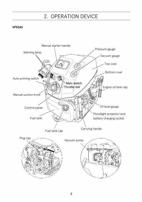
2. OPERATION DEVICE
VF53AS
2
Plug cap Vacuum pump
Manual starter handle
Warning lamp
Auto priming switch
Manual suction knob
Control panel
Fuel tank
Fuel tank cap Carrying handle
Floodlight projector and battery charging socket
Oil level gauge
Engine oil tank cap
Bottom cowl
Top cowl
Vacuum gauge
Pressure gauge
Main switch Throttle dial

5
2. OPERATION DEVICE
VF53AS
Ball valve type
Screw down valve type Discharge valve handle
Latch (for top cowl)
Discharge valve’s drain valve Cooling water strainer
Vacuum pump strainer
Muffler
Muffler drain valve
Air valve for drainage Pump drain valve
Suction hose coupling cap

6
2. OPERATION DEVICE
VF63AS-R
Different operation part from VF53AS
Warning lamp
Main/Start switch
Control panel
Stop switch
Operation mode switch Priming water mode switch
Throttle dial

7
3. LABEL
3
Label Danger : Fuel Warning : Exhaust gas
Instruction label
Operation procedure

8
4. OPERATING PRECAUTIONS
Installing pump
The fire pump must be installed on level ground. Otherwise, an accident may occur. If the fire pump should be installed on uneven ground, it must be secured.
4 Place the pump as near as possible to water source, and water suction height as low as possible. When putting the portable fire pump down on the ground, put it gently and horizontally. In case of the inclined location or uneven ground, make sure that water suction hose is lower than suction port of the pump. In case of the suction hose is put undulated, air can be left easily in the hose, and possibly cause suction inability when the water discharge valve is opened. In case of the suction inability due to air remaining in the suction hose, set the water discharge valve half-opened, and operate vacuum pump until water is discharged continuously. (More operation of vacuum pump for 3 to 5 seconds from beginning of water discharge.) Be sure to install strainer and basket at the end of suction hose. If the pump may suck sand or mud of the water source bottom, place sheet below the basket.
Strainer and basket of suction hose should be placed more than 30 cm below water surface to prevent suck of air.
Discharge hose should be arranged not to be bent.
NOTE
CAUTION

9
4. OPERATING PRECAUTIONS
When installing the portable pump in a vehicle, place the vehicle on a level place, and install the pump. When installing the portable pump in the vehicle, make sure to apply the brakes of the vehicle in order to stop the wheels. A serious accident may occur if the vehicle moves. Do not put your hand or finger in the retractable part when using the handle. When transporting the portable fire pump, assign one person per handle. Also, when you transport the portable fire pump, it should be transported holding the handle firmly on each to avoid falling down the pump.
When lowering the portable fire pump to the ground, lower it gently and horizontally.
Do not touch the exhaust pipe and the muffler while the engine is running, or for more than 10 minutes after the engine has been stopped. These parts are very hot and will cause severe burns.
CAUTION
Do not put your hands or fingers
NOTE
CAUTION

10
5. DESCRIPTION OF DEVICES
Carrying handle The fire pump is equipped with four carrying handles. The handles can be manually folded, and opened by turning them by 90 degrees.
Personal injuries may occur when opening or closing the handle. Do not put your hands or fingers into the retractable part when operating the handle. To prevent injuries, two persons should work together when carrying and placing the pump.
Opening cowl
1. Lift the latch up on the rear side and remove the cowl.
2. Remove the cowl latch from the plate at the front side of the pump.
3. Remove the cowl.
Carrying handle
Carrying handle
Cowl latch
Plate
CAUTION

11
5. DESCRIPTION OF DEVICES
Assembling cowl Assembling order is in reverse order of the opening.
Pay attention to have the starter handle for manual starting go through the window at the front- upper side of the upper cowl.
Suction port
The diameter of the thread for the fire pump is JIS fire thread (B-9912) 3” (75 mm) or BSP thread 4" (100 mm).
if you insert your finger into the suction port while the pump is running, you may be seriously injured by the spinning inducer.
A strainer must be installed at the suction port. Do not run the pump if the strainer is not installed. If the pump is running without the strainer, gravel may enter the pump and causes significantly reduced water discharge capacity.
Thread
Suction port
Starter handle
NOTE
CAUTION
WARNING

12
5. DESCRIPTION OF DEVICES
Discharge port The diameter of the thread for fire pump,
JIS fire thread (B-9912) 2-1/2” (65 mm) BSP thread 2-1/2" (65 mm)
Discharge valve Use discharge valve handle for opening and closing the discharge valves.
Screw down discharge valve _______
Ball cock discharge valve __________
Drain valve
Use the drain valves to drain water from the pump.
Drain valves:
- Pump case - Muffler - Engine (Air intake valve to assist drainage) - Ball cock discharge valves (Only for ball cock
discharge valve type)
Valve-air for drain
Valve (Muffler)
Valves (Pump case)
Valve (Ball valve)
Thread Handle
Handle

13
5. DESCRIPTION OF DEVICES
Priming knob Use for priming water by manual operation. After starting the engine, pull the priming knob to suction water. After priming water has been completed, return the priming knob to its original position.
Fuel tank
Refill appropriate amount of gasoline to the fuel tank.
Close the fuel tank cap all the time except refuel. Engine oil
Before using the pump, fill it with the designated amount (approximately 1.9L / 0.50gal(US)) of 4-stroke engine oil.
Fill the engine oil until “Upper” level.
Fill the 4-stroke engine oil.
Priming knob
Fuel tank cap
Filler cap Oil pan
NOTE

14
5. DESCRIPTION OF DEVICES
Control panel The control panel is equipped with all the necessary operating and control instruments as follows.
Main switch
Throttle dial
All warning lamps Throttle dial
Auto priming switch.(VF53AS) Priming water mode switch.(VF63AS-R)
Warning lamp & buzzer
Turning the main switch to the “ON” position, the lamp and buzzer check mode starts. The warning lamps turn on and the warning buzzer sounds for a moment while the check mode operates. If the lamp and buzzer check mode would show failure, refer to “Chapter 16 TROUBLESHOOTING” to eliminate the cause.
Remove the cause of failure by following “Chapter 16 TROUBLESHOOTING”.
VF53AS
Auto priming switch
Main switch Warning lamp
Throttle dial
VF63AS-R
Throttle dial Main switch
Priming water mode switch
Warning lamp
CAUTION

15
5. DESCRIPTION OF DEVICES
The monitor indicates the following information. ・ Fuel level warning ・ Engine oil pressure warning ・ Overheat warning ・ Suction failure warning
Fuel and Engine oil warning
In the case of fuel level in the fuel tank is below approximately 1/3, the warning lamp turns on and the warning buzzer sounds continuously when the main switch is turned on. In the case of oil pressure drops, the warning lamp blinks slowly and the warning buzzer sounds continuously when the main switch is at ON position. In the case of oil pressure switch is defective or the circuit is disconnected, the warning lamp blinks slowly when the main switch is turned on.
In the case of slow blinks or lighting, take countermeasures following “Chapter 16 TROUBLESHOOTING”
The lamp turns on and warning buzzer sounds instantaneously when the main switch is turned on, is normal. The lamp turning on instantaneously shows the system check operation has done.
VF53AS
Fuel and Engine oil warning
VF63AS-R
Fuel and Engine oil warning
CAUTION
NOTE

16
5. DESCRIPTION OF DEVICES
Engine overheat and Suction failure In the case of engine stop due to insufficient cooling water, the warning lamp turns on and the warning buzzer sounds continuously. In the case of engine stop due to unable suction water complete within 30 seconds in the auto priming mode, the warning lamp blinks slowly and the warning buzzer sounds continuously. In case of TPS,MAT,MAP or WTS is defective or the circuit is disconnected, the warning lamp blinks fast and the buzzer sounds intermittently when the main switch is turned on.
The engine may be damaged. Do not restart the engine soon after it has stopped running. Take countermeasures first following “Chapter 16 TROUBLESHOOTING”
The engine stops automatically when the overheated is detected. The lamp turns on and sounds when the main switch is turned on, is normal. The lamp turning on instantaneously shows the system check operation has done.
Main switch VF53AS
Main switch position and function Description Function
OFF To stop the pump running ON Running position Start To start the pump running
VF63AS-R Main switch situation and function Press the main switch to run or to stop the pump.
Description Function
Light off To stop the pump Light on To start the pump, or running
Overheat and Suction failure
VF53AS
VF63AS-R
Main switch
VF63AS-R
Overheat and Suction failure CAUTION
NOTE
VF53AS
Main switch

17
5. DESCRIPTION OF DEVICES
Auto priming Auto priming switch (VF53AS)
In the case of turning on the auto priming switch, running the engine and turning the throttle to water suction position, the pump starts to suck water.
Priming water mode switch (VF63AS-R) Make the switch light off (Priming water mode switch light off). (Press the priming water mode switch if needed.) Start the engine and turn the throttle dial to suction water position, and then the pump starts to suck water automatically.
Do not manual operation of pulling priming knob when the automatic priming water switch is “ON” mode.
Pressure gauge for discharge
The pressure gauge for discharge indicates the actual operating water pressure.
Pressure gauge for suction
The pressure gauge for suction indicates the suction side water pressure and the input pressure supplied from an external water source.
Manual starter In the case of the battery is not sufficiently charged to start the engine, use the manual starter to start the engine.
Do not pull the manual starter handle when the pump is running. Personal injuries may occur. Otherwise, the manual starter may be damaged. Using the manual starter, pull the starter handle at a breath from feeling the handle heavier to start the engine.
VF53AS
Auto priming switch
Pressure gauge for discharge
Pressure gauge for suction
Manual starter handle
CAUTION
CAUTION
NOTE
VF63AS-R
Priming water mode switch

18
5. DESCRIPTION OF DEVICES
Cooling water recirculation system This system is to recirculate the cooling water without draining outside. Accordingly, the engine does not have a cooling water drain hose.
Overheat prevention device This device monitors the engine temperature with a water temperature sensor. When the engine temperature rises over the setting temperature (approximately 90 C) or higher, warning buzzer alarms and automatically the engine stops to prevent overheating.
・Status of the lamp after the overheat prevention device is actuated. ① If the engine is restarted while the main switch is being at RUN position, the alarm
lamp will turn on (an alarm buzzer will also sound). ② If the engine is restarted after the main switch turned to STOP position once, the
alarm lamp will go off (reset). The alarm buzzer will not sound, either. ・Precautions for restarting after the overheat prevention device is actuated ① Resolve the cause of the abnormally high engine temperature, and then restart
the engine. If the cause of the abnormally high engine temperature has not been resolved, the engine will stop again within approximately 30 seconds.
(The time in seconds until engine stop varies depending on the temperature of the engine.)
② The starter motor runs when the engine temperature exceeds approximately 120 C, but the engine prevention function is actuated and the pump cannot be restarted.
Do not repeatedly restart the engine without resolving the cause of the abnormally high engine temperature.
NOTE

19
5. DESCRIPTION OF DEVICES
Electric Safety Governor (ESG) Designed as a system to assist the mechanical governor, the electric governor controls the maximum engine speed by cutting off ignition so that the engine speed does not exceed 6100r/min.
Battery save control If the engine being power ON but it is not started within 30 minutes, the power automatically turns OFF.
Initial charge of battery The battery can be used immediately after filling cells with electrolyte. Be sure not to open the battery after filling it with electrolyte. (Maintenance free battery) Refer to the INSTRUCTION of the battery.
Battery charger socket Connect the battery charger plug to the socket to charge the battery of the pump.
<Specifications of accessory socket> ・ Voltage: DC12V
・ Max. allowable current: 7.5A
・ Before charging the battery, turn off the main switch.
・ When starting operation, be sure to remove the battery charger before turning the m a i n switch ON.
・ The socket is for a battery and a floodlight.
・ Do not connect a cigarette lighter to the socket, because it is not a heat-resistant object.
Battery charger
CAUTION
Battery charger

20
5. DESCRIPTION OF DEVICES
Fuse box Security fuses are installed for electrical circuit in the fuse boxes. There are two fuse boxes:
- Black color fuse box: 15A fuse. - Yellow color fuse box: 7.5A fuse.
(And 2A fuse (VF63AS-R))
Manual starter If the engine does not start with a starter motor, use a manual starter.
Do not pull the manual starter handle when the pump is running. Personal injuries may occur. Otherwise, the manual starter may be damaged.
To start the engine with manual starter, engage the manual starter ratchet by pulling the starter rope slowly. And then pull the starter handle quickly with great force from the position in which feeling harder resistance.
Fuse box
Manual starter handle
CAUTION
NOTE

21
5. DESCRIPTION OF DEVICES
Floodlight (Option) Use the floodlight projector to light up the location where the fire pump works.
Loosen the adjust screw ① and pull up the floodlight projector ② to adjust its height. After the adjustment is completed, tighten the adjust screw.
・ Secure enough lighting for the location where the fire pump works, otherwise an accident may occur.
CAUTION
Floodlight socket
①
②
Bulb 12V-55W Plug

22
6. PREPARATION FOR OPERATION
Fuel Fill the tank with gasoline until the maximum level of the (Red) gauge indication.
Fuel tank capacity: 10L (2.6gal(US))
・ Vaporized fuel may cause ignition or an explosion.
・ Do not bring any flames near fuel. ・ Stop the engine before refilling fuel. ・ Do not spill fuel. ・ Do not overfill fuel into the tank.
・ Do not breathe in vapor! Petrol fumes are
very toxic. ・ After stopping the engine, do not touch it
while it is hot. ・ Refill fuel after the engine has cooled down. ・ Close the fuel tank cap tightly. ・ Remove the fuel tank cap only in the case of
filling fuel to the tank or checking inside of the tank.
・ Properly clean out all spilled fuel (checking for gasoline vapor) before starting engine.
・ If petrol or fuel spills, wipe it off using a cloth or other materials, and dispose them according to the relevant laws and regulations.
DANGER
Level gauge
CAUTION

23
6. PREPARATION FOR OPERATION
・ Use of low-quality fuel results in a short engine life as well as starting difficulty and other engine problems.
・ Fuel containing alcohol, methanol (methyl), or ethanol (ethyl), may cause:
・ Deterioration of rubber parts and plastic parts. - Starting, idling and other engine performance problems.
・ Do not use fuel that contains more than 10% ethanol or more than 5% methanol.
・ Damages resulting from the use of fuel that contain alcohol are not covered under the limited warranty.
・ Keep fuel tank full with gasoline at all times to ensure readiness. Engine oil
Before using the pump, fill it with the designated amount
Fill the engine oil until “Upper” level. 1. Check the engine oil level before engine start. 2. To confirm the engine oil level correctly, keep the
engine stopped for more than 24 hours. After that, check the oil level.
3. Refill appropriate amount of oil to the oil pan.
4. Close the Oil tank cap all the time except filling.
・ If the engine oil is not enough filled, turning switch “ON”, then the warning buzzer sounds. Always wipe off spilled engine oil.
・ Fill 4-stroke engine oil. (Approximately 1.9L / 0.50gal(US))
・ Check the engine oil level before engine start. To confirm the engine oil level correctly, keep the engine stopped for more than 24 hours. After that, check the oil level.
Oil pan Filler cap
NOTE
NOTE
CAUTION
24
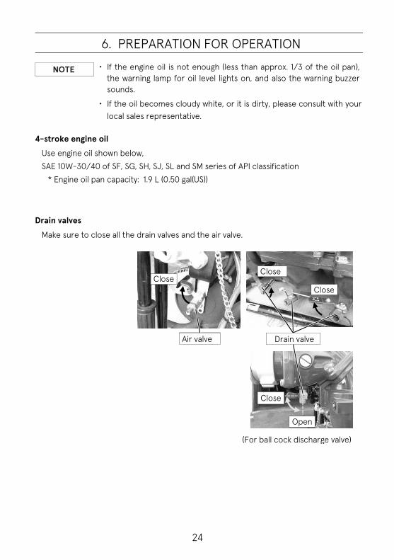
6. PREPARATION FOR OPERATION
・ If the engine oil is not enough (less than approx. 1/3 of the oil pan), the warning lamp for oil level lights on, and also the warning buzzer sounds.
・ If the oil becomes cloudy white, or it is dirty, please consult with your local sales representative.
4-stroke engine oil
Use engine oil shown below, SAE 10W-30/40 of SF, SG, SH, SJ, SL and SM series of API classification
* Engine oil pan capacity: 1.9 L (0.50 gal(US))
Drain valves Make sure to close all the drain valves and the air valve.
Drain valve
(For ball cock discharge valve)
Air valve
Close
Close
Open
Close Close
NOTE

25
6. PREPARATION FOR OPERATION
Discharge valve Close the discharge valves and the drain valves.
Screw down discharge valve________
Ball cock discharge valve __________
・ It is possible to lock the direction of the valve by tightening the lock(positioning) bolt.
・ Do not change the direction of the water discharge valves if the lock bolt is tightened.
Close
Close
Lock bolt
Close
Close NOTE

26
7. USE OF CONTROL PANEL
Control Panel
VF53AS
VF63AS-R
⑫Start switch (Main switch)
① Warning lamp
② Warning lamp Throttle,
Start/Low pressure position
Throttle, Suction position
⑨ Stop switch
⑩ Operation mode switch
⑪ Priming water mode switch
③ Warning for refueling
⑬ Throttle dial
④ Warning for engine trouble
⑤ Warning for engine overheat
⑦ Priming water mode
switching display
⑧ Throttle opening indicator
① Warning lamp
② Warning lamp
Auto priming switch
⑬ Throttle dial
Throttle, Suction position Throttle,
Start/Low pressure position
Main switch
⑥ Warning for unable to suction
water or start engine

27
7. USE OF CONTROL PANEL
Warning lamp
① Warning lamp
Light on: Fuel shortage. Slow blinking: Engine oil pressure reduced. Fast blinking: Failure of engine oil pressure switch.
Circuit break.
② Warning lamp
Light on: Engine stop due to overheating. Slow blinking: Unable suction water in 30 seconds. Fast blinking: Failure of TPS, MAT, MAP, WTS.
Circuit break.
③ Warning for refueling Light on: Fuel shortage. (Fuel level is below
approximately 1/3 of fuel tank.)
④ Warning for engine trouble
Light on: Engine trouble. (Electronic throttle failure, Engine oil pressure reduced.)
⑤ Warning for engine overheat
Light on: Operation of overheat prevention device.
⑥ Warning for unable to suction water or start engine
Light on: Unable to suck up water. (Water suction is not complete within 30 seconds in automatic water suction mode.)
⑦ Priming water mode switching display
Display for chosen water suction mode. Light off:Auto Slow blinking:Manual
⑧ Throttle opening indicator Shows throttle opening level. (9 steps)
Switch
⑨ Stop switch Stop engine. / Power off.
⑩ Operation mode switch
One-push: Power ON. Long pushing: Switching of operation mode.~
Stand-alone / Relay pump
⑪ Priming water mode switch
Switching of water suction operating mode.~Auto / Manual
⑫ Start switch (Main switch)
Power on / Start engine with starter.
Other
⑬ Throttle Dial Throttle opening. (Manual)

28
7. USE OF CONTROL PANEL
Pictogram Warnings will be also displayed by light on pictograms. (VF63AS-R)
Fuel shortage Light on: Amount of fuel in the fuel tank is 1/3 or less. ・Refill fuel.
Engine trouble Light on (Only the pictogram): Engine oil pressure reduced. ・Check the quantity of engine oil and refill the oil. if the oil level is in
the specified level, contact the dealer. Light on (The pictogram and the throttle opening indicator)
: Electronic throttle problem (Motor malfunction, sensor failure, disconnection)
・Stop the engine, contact the dealer.
Overheat Light on:Overheat prevention device operates. ・Eliminate the cause of cooling water shortage. Then after, start the
engine again.
Unable to suck up water completely Light on:Sucking water is not completed within 30 seconds. ・Refer to " Chapter16 TROUBLESHOOTING”. Eliminate the cause
of failure. Then after, start the engine again. Inability of starting Light on:In automatic relay pump operation mode, the engine does not start even if the start pattern is repeated six times. ・Eliminate the cause of starting inability. Then after, start the
engine again.

29
7. USE OF CONTROL PANEL
Alarm indication for electronic throttle trouble In addition to the standard type warning, VF63AS-R type has warnings for electronic throttle abnormality.
Warning indication
・ Warning lamp 1:Slow blinking ・ Engine failure warning lamp:Light on ・ Throttle opening indicator: Blink alternately between odd and even numbered.
・ Buzzer : Continuous sound ・ Low speed ESG: Operate (Engine speed is controlled at around 2800r.p.m.)
Faulty part
Electronic throttle Motor malfunction, sensor failure, disconnection
Remedy
Stop the engine, contact the dealer.

30
7. USE OF CONTROL PANEL
When the warning lamps are all off, there is no problem on each function. * Countermeasures (Warning lamp turns ON)
It is necessary to take a countermeasure if the lamp lights up when turning the main switch to the “ON” position. Then take a countermeasure referring to “Chapter 16 TROUBLESHOOTING”.
Warning system
Warning indicator
Abnormal Phenomenon
Remedy
Warning lamp
Warning lamp
Buzzer H
igh-speed ESG
Low-speed ESG
Engine Speed
Fuel Supply. Abnormal oil pressure.
Overheat. Suction Disabled.
Instantan-eously light
Instantan-eously light
Instantan-eously sound
It is normal because these are system check operation when starting the system. *1
Light Continuous sound
Fuel level in tank is below approximately 1/3.
A
Slow blinking Continuous
sound ON Engine oil pressure drops. *2 B
Light Continuous sound Stop
Engine stops due to insufficient cooling water. *3
C
Slow blinking
Continuous sound Stop
Engine stops if it is unable to perform suction water completed within 30 seconds of automatic water supply.
D
ON Exceeded allowable engine speed.*4 E
Fast blinking
Intermittent sound
TPS, MAT, MAP or WTS is defective or circuit is disconnected. *5
F
Slow blinking
Oil pressure switch is defective or the circuit is disconnected. *6
F

31
7. USE OF CONTROL PANEL
*1 When the main switch is turned at the ON position. *2 The engine speed is controlled at 2800rpm. *3 ・When the cooling water temperature reaches approximately 90 C or higher, the
overheat prevention device is actuated and stops the engine. ・ Even if the cooling water temperature exceeds approximately120 C, the cell motor
can be run. But the engine prevention function is actuated and the pump cannot be restarted.
*4 The engine speed is controlled at 6100 rpm.
*5 TPS (Throttle position sensor) MAT (Manifold air temperature sensor) MAP (Manifold air pressure sensor) WTS (Water temperature sensor)
*6 When the main switch is turned at the RUN position and before the engine starts running.
Remedy a. Replenish fuel. b. Inspect the amount of engine oil; if it is below the designated level, replenish oil. If
the designated oil level is satisfied, consult with the sales representative.
Check the engine oil level before engine start. To confirm the engine oil level correctly, keep the engine stopped for more than 24 hours. After that, check the oil level.
c. Correct the cause of cooling water insufficiency, and then restart the engine. d. Correct the cause of abnormality by referring to “Chapter 16 TROUBLESHOOTING”,
and then restart the engine. e. Turn the throttle dial to the low pressure side. There is a possibility of not enough
water remain in the suction water line. f. Except of emergency, stop the engine and consult with your local sales
representative.
NOTE

32
7. USE OF CONTROL PANEL
Warning lamp and sensor Turning the main switch to the “ON” position, warning lamps light up and the buzzer sounds for a moment, which shows the alarm checking is done.
・ After the engine has stopped due to overheating, if you restart the engine immediately, engine may be burnt. Before restarting the engine, eliminate the cause. (Refer to “Chapter 16 TROUBLESHOOTING”)
・ After that, check that the warning lamps are turned off.
Overheat warning lamp (Warning lamp ②)
This device monitors the cooling water temperature with a water temperature sensor. In the case of water temperature reaches the setting temperature of approximately 80 C, it sounds buzzer alarming and the warning lamp ② lights.
In the case of water temperature reaches the setting temperature of approximately 90 C or higher, it sounds buzzer alarming, the warning lamp ② lights and automatically stops the engine.
Status of the alarm after the overheat prevention device actuated 1. If the engine is restarted while the main switch is being at “ON”position, the alarm
will turn on. A warning buzzer will also sounds.
2. If the engine is restarted after the main switch is turned off once, the alarm lamps will go off (reset). An alarm buzzer will not sound.
VF53AS
Warning lamp ①
Warning lamp ②
VF63AS-R
Warning lamp ①
Warning lamp ②
CAUTION

33
7. USE OF CONTROL PANEL
Precautions for restarting after the overheat prevention device actuated 1. Resolve the cause of the abnormally high cooling water temperature, and then
restart the engine. If the cause of the abnormally high cooling water temperature has not been resolved, the engine will stop again within approximately 30 seconds. (The time in seconds until engine stop varies depending on the temperature of the cooling water.)
2. After resolving the problem for overheat, in the case of cooling water temperature is even if more than 90°C, it is possible to start the engine temporarily. This makes possible the effective cooling down the engine temperature by pumping up lower temperature water.
3. The starter motor can be run even if the cooling water temperature exceeds approximately 120°C, but the engine prevention function works and the pump cannot be restarted.
After eliminating the cause of overheating and solving the problem, restarting the engine, pump up water and discharge water, then the cooling water temperature in the engine goes down, and then the warning lamp turns off and the warning buzzer stops.
・ Do not repeatedly restart the engine without resolving the cause of the abnormally high cooling water temperature.
Closed Circulating Water Cooling System
In this system, engine cooling water is taken from the pumping up water, and pressurized by the pump. A part of the water goes through the engine and the muffler, and returns to the water intake of the pump.
Warning device check
・ When the main switch is turned ON, the warning lamps and buzzer will be activated for approximately one second. After one second, the warning lamps are all turned off in the condition of power ON, it shows there is no problem on each function.
・ If the warning lamps turn on or blinking, the function does not work properly.
CAUTION
NOTE
34
8. STARTING THE ENGINE
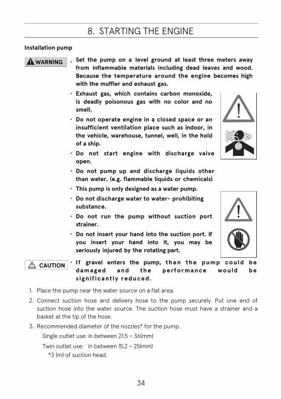
Installation pump
・ Set the pump on a level ground at least three meters away from inflammable materials including dead leaves and wood. Because the temperature around the engine becomes high with the muffler and exhaust gas.
・ Exhaust gas, which contains carbon monoxide, is deadly poisonous gas with no color and no smell.
・ Do not operate engine in a closed space or an insufficient ventilation place such as indoor, in the vehicle, warehouse, tunnel, well, in the hold of a ship.
・ Do not start engine with discharge valve open.
・ Do not pump up and discharge liquids other than water. (e.g. flammable liquids or chemicals)
・ This pump is only designed as a water pump. ・ Do not discharge water to water- prohibiting
substance. ・ Do not run the pump without suction port
strainer. ・ Do not insert your hand into the suction port. If
you insert your hand into it, you may be seriously injured by the rotating part.
・ I f gravel enters the pump, th e n t h e p u mp co ul d be d a m a g e d a n d th e p e rfo r ma n ce wo uld be s i g n i f i ca nt l y r ed u c e d.
1. Place the pump near the water source on a flat area.
2. Connect suction hose and delivery hose to the pump securely. Put one end of suction hose into the water source. The suction hose must have a strainer and a basket at the tip of the hose.
3. Recommended diameter of the nozzles* for the pump. Single outlet use: in between 21.5 ~ 36(mm)
Twin outlet use: in between 15.2 ~ 25(mm) *3 (m) of suction head.
WARNING
CAUTION

35
8. STARTING THE ENGINE
Starting engine
・ Wear a proper hearing protection during operation.
・ While the engine is running, never touch the high voltage ignition wire attached to spark plug. This wire carries very high voltage which will cause injury and bodily harm.
・ Do not operate the pump on dry grass. The exhaust system will be very hot and could cause the dry grass burnt and fire. Clear the area if necessary.
Make sure that all the discharge valve(s) is closed.
Make sure to turn on the “Auto priming” switch.
VF53AS: In the case of the “Auto priming” switch is “ON” position, if water supply is not achieved in 30 seconds, then the engine will stop.
VF63AS-R: In the case of “Priming water mode switch” status is Auto (the switch lights off), if water supply is not achieved in 30 seconds, then the engine will stop automatically.
Operate it according to the operating procedure number indicated on the pump.
Close
CAUTION

36
8. STARTING THE ENGINE
VF53AS 1. Turn the throttle dial to the “Start” position.
2. Turn the main switch to the “ON” position and
starts.
VF63AS-R 1. Turn the throttle dial to “Low pressure” position.
2. Press the main switch until the engine starts.
Extended operation of the starter motor will run the battery drain. Limit the operating time of starter motor maximum 3 seconds at one time. If the engine does not start, wait for 5 seconds before operating the starter motor again. Do not operate the starter motor after the engine started. If the starter motor does not work, check that the battery terminals are tightly connected and the battery is fully charged.
Starting engine using the manual starter If electric starter does not work, use the manual starter.
・ Even an insufficient charge battery, install the battery to start the engine and operate the pump.
- VF53AS - 1. Turn the throttle dial to the start (Low pressure)
position, and turn on the main switch. Start the engine by pulling the starter handle forward. *Engage the manual starter ratchet by pulling the starter rope slowly. And then pull the starter handle quickly with great force from the position in which feeling harder resistance.
2. Once the engine starts, turn the throttle dial to the suction position.
*Operate the pump as the same way with battery started case.
Starter handle
VF53AS
Main switch
Throttle dial
VF63AS-R
Main switch
Throttle dial
NOTE
NOTE

37
8. STARTING THE ENGINE
In the case of the auto priming switch is ON, the vacuum pump will run automatically. In the case of the auto priming switch OFF, pull the priming knob to prime water.
3. Pull the manual suction knob, and operate the vacuum pump. Confirming the completion of suction water, then return the throttle dial to the low pressure side.
- VF63AS-R -
1. Turn the throttle dial to the start (Low pressure) position. Start the engine by pulling the starter handle forward. Pull it until the handle feels heavy, then pull it with great force.
2. Once the engine starts, operate the pump as the same way with the starter motor/battery started case.
・ Keep the operating time of the vacuum pump within 30 seconds. ・If suction cannot be done within 30 seconds, there is the other
problem.
Dry operation This portable pump has outsource cooling system, limit the duration of dry operation* so that it is within the following time periods.
*Dry operation: Running engine without water. Performing dry operation longer than the specified time period may cause damage to the engine or pump.
・ Throttle dial at idle position: Within 2 minutes ・ Throttle dial at start position: Within 30 seconds
Closed discharge valves operation after priming water
When the pump is operated with the discharge valve closed, the cooling water temperature becomes high.
・ Do not run the engine with opened recoil starter to avoid serious injury.
・ If you continue the closed discharge valve operation after suck up water, the pump will be overheated.
Priming knob
CAUTION
NOTE
WARNING

38
9. PRIME AND DISCHARGE
While the engine is running with the cowl removed, do not touch the rotating parts such as the pulley or belt. This may cause personal injuries.
If, when operating the vacuum pump for 30 seconds, the pump does not suck up water or if the water can not to be pumped up continuously by the pump during the water discharge operation, check the following: Is the tip of the suction hose completely below the water surface? Is the suction hose damaged? Does the vacuum performance of the priming pump reduced significantly? Does the pump case leak vacuum? Does the vacuum leak occur when the pump is connected with the suction hose which is capped at the tip of the hose?
Refer to “Chapter 16 TROUBLESHOOTING”.
1. Once the engine starts, turn the throttle dial to the suction position.
2. The vacuum pump operates automatically until the
suction finished (Maximum operating time is for 30 seconds). When the suction finished, the vacuum pump automatically stops.
3. When the vacuum pump stops, return the throttle
dial to the low pressure side.
VF53AS
Main switch
Throttle dial
VF63AS-R
Main switch
Throttle dial
NOTE
WARNING

39
9. PRIME AND DISCHARGE
In the auto priming mode, The vacuum pump runs at around 1800rpm. If water cannot be supplied within 30 seconds, the engine will stop automatically. If the engine speed is lower than 1300 rpm and the vacuum pump is not operated, the engine will stop automatically in about 30 seconds.
4. Check that the pumped up water is discharged from the priming outlet of the vacuum pump, and be sure the pressure gauge shows positive side.
The vacuum pump automatically operates for 30 seconds. If suction water cannot be completed within the time the vacuum pump operates, there are some other problems. Check the cause.
(Refer to “Chapter 16 TROUBLESHOOTING”) Start to discharge water after informing the people who are on the hose side.
5. Open the discharge valve handle slowly to start discharging water.
Before opening the water discharge port or valve of the pump, confirm the operators holding the nozzle or the branch pipe, that have already checked the nozzle opened and ready to discharge water. During operation, check the suction and discharge hoses. It must be free of kinks, pinches, etc., possibly caused from emergency vehicles rolling over hose.
To avoid the air left in the hose, the pump should be located above the suction hose. If some air left in the hose, the pump may not be able to discharge water by the accumulated air in the hose when you open the discharge valve. In this case, open the discharge valve and operate the vacuum pump for 3 to 5 seconds until the water is continuously discharged.
NOTE
NOTE
CAUTION
NOTE
Nozzle

40
9. PRIME AND DISCHARGE
Checking the pressure and gradually turn the throttle dial to adjust the pressure.
In the case of using a branch pipe, the person holding the branch pipe must be notified of changes in water discharge pressure caused from engine speed changes or discharge water valve opening setting changes. Do not direct the nozzle toward people under any circumstances. Do not look into the nozzle opening at any time. Do not put fingers or a hand into the discharge nozzle.
Throttle dial
Pressure gauge
CAUTION

41
9. PRIME AND DISCHARGE
Relay pumping water operation
In the case of relay pumping operation training in a flat place, if the number of extending hose is less than ten, use the safety nozzle attached.
Description of relay pumping operation
Packing Pumping
plate
Discharge port adaptor (OPTION)
CAUTION

42
9. PRIME AND DISCHARGE
Performing relayed water supply (When having water from fire hydrant) 1. Decide the pump pressure in consideration of the water discharge pressure
(nozzle pressure), height loss and hose pressure loss (friction loss).
2. Foreign materials such as dirt, gravel, iron rust, etc. may in a fire hydrant. Before connecting a hose, open a fire hydrant to discharge water in order to remove foreign materials.
3. When pumping up water from a fire hydrant, use a mediation metal and use a delivery hose (for high pressure) to connect the suction port instead of a suction hose in principle.
4. Set the discharge valve handle of the pump to the full open position. 5. Gradually open the fire hydrant on-off valve.
However, check the water pressure from the fire hydrant with suction pressure gauge of the pump, and adjust the opening of fire hydrant, if necessary.
If the water pressure from a fire hydrant is higher than 0.6MPa (87psi), do not continue to open the fire hydrant on-off valve.
*・ If the water pressure from a fire hydrant is higher than the required discharge pressure, it is not necessary to run the pump.
If the water pressure from fire hydrant has not reached the required pressure, start to run the engine.
6. If the water pressure from fire hydrant is insufficient, start the engine and adjust the pressure to the required level by operating the throttle dial. Stop increasing discharge pressure if the suction pressure gauge shows 0.1MPa (15psi) or below. If it does, stop increasing the pressure and keep (Operate) the throttle dial not to make the suction water side pressure below 0.1MPa (15psi).
7. At the end of discharging water, turn the throttle dial to the low pressure position first, then stop the engine, and close the fire hydrant on-off valve.
Make sure not to close the discharge valve(s) and nozzle(s) before all pumps stop and the fire hydrant on-off valve is closed.
8. Open all the drain valves to drain the remaining water as maintenance after the operation. In the case of ball cock type water discharge valve, open the drain cock which is at the down side of the valve, turn the valve handle to the half-open position to drain all the water from the valve.
Pump pressure = needed pressure + height loss+ friction loss
CAUTION
CAUTION

43
9. PRIME AND DISCHARGE
Preparation for operation
Do not close the discharge valve of source pump, relay pumps and fire nozzle(s). If the discharge valves or nozzle is (are) closed, there will be a risk of damage to the pumps and hoses with excessive pressure or water hammer.
1. Decide how many relay pumps are needed in consideration of distance and height between the water sauce and the fire ground.
2. Place the pumps according to the decision, and connect the hoses. 3. Make sure that the discharge valves are all opened, including the fire nozzles. 4. Decide the discharge pressure of each pump in consideration of the needed
pressure for the next pump (or fire nozzle), height loss and hose pressure loss (friction loss).
Start the source pump
Once the water supply has started, keep supplying it until finished. If reducing or stopping to supply water, overheat or cavitation may occur in the relay pumps.
< Auto priming> 1. Make sure that the discharge valves and the fire nozzle(s) are all opened. 2. Turn the auto switch on. ・VF53AS: Turn on the auto priming switch. (In the case of choosing the manual mode,
priming water must be done by manual.) ・VF63AS-R: Choose the operating mode of stand-alone.
Press the "operation mode switch" if necessary. Choose the priming water mode of Auto (or Manual) by pressing the switch of “Priming water mode switch”.
3. Start the source pump. (Refer to “Chapter 8 ENGINE START”) 4. Start the engine run, and turn the throttle dial to the suction water position.
*The pump will start to suck up water if the priming water mode switch is chosen auto mode. If the priming water mode switch is chosen manual mode, suck up water using a priming knob.
Pump pressure = needed pressure + height loss+ friction loss
WARNING
WARNING

44
9. PRIME AND DISCHARGE
Start the relay pump 1. Make sure that the discharge valve is opened and wait for supply water.
VF53AS: Turn off the auto priming switch. VF63AS-R: Press the "Operation mode switch" if necessary. Choose the relay pump mode*. * Press the "Operation mode switch" one time for about 2 seconds to switch the
relay water supply mode. And then confirm that the switch turns on red and buzzer sounds (intermittent sound). In the case of choosing the stand-alone mode, the operation of the relay pump is the same with VF53AS.
At first, the hose swells due to air pressure. Check that the water was supplied from the source pump, step on the hose to judge whether the swelling of the hose is due to water or air if possible.
2. When the water pressure of the relay pump raised to more than 0.1MPa(15psi) due to the water sent from the source(previous) pump, (If it becomes clear that water was supplied to the pump,)
- VF53AS - Start the engine run. Check pressure with the pressure gauge. And start the engine when it is lower than the decided pressure. If the pressure is higher than decided pressure, no need to start the engine. Adjust the discharge pressure with throttle dial. Always check the discharge pressure and suction pressure with the pressure gauges. If the suction pressure goes down below 0.1MPa (15psi), order the operator of the pre-stage pump to increase the discharge water pressure, and adjust the relay pump pressure by the throttle. If the suction pressure rises, adjust the pressure with throttle dial again.
- VF63AS-R - The relay pump starts automatically. (Refer to *1. Start cycle control.) The pump controls the suction water pressure which is about 0.15MPa (22psi). While the relay pump mode is chosen, no need to adjust the pressure. The throttle dial does not work while the relay pump mode is chosen. To change the running mode of the pump from Relay to Stand-alone or Stand-alone to Relay pumping operation while relay pumping operation is running, the throttle dial position should be at "Low pressure position”. Check the throttle dial position. Press the operation mode switch " for about 2 seconds to change the mode, and check the mode (Switch light: Blue/Red).

45
9. PRIME AND DISCHARGE
If the suction side water pressure goes down below 0.05 MPa (7psi) for about 15 seconds, the pump will stop automatically. To stop at emergency, press the stop switch.
*1. Start cycle control ・Standby mode: Switching the pump mode to the relay water supply mode,
throttle motor position will be at low pressure position, and checking the suction water side pressure.
・Control the starting: When the water pressure of the pump rises above 0.13MPa(19psi) by the water from the source (previous) pump, the engine starts automatically.
Starter motor operates for 3 seconds automatically. If the engine doesn't start, starter motor runs again. (Max 6 times) This is for stable starting operation by the starter motor and save battery energy. If the engine doesn't start in 6 times starting operations, then warning lamp ② starts slow blinking (Unable to start engine).
・ Air-Water decision: Even if a large amount of air comes from the source(previous)pump to the relay pump, the pump internal pressure could rise, and the relay pump may start. In the relay pump of VF63AS-R, whether this raised pressure is due to air or water would be judged. If it is judged that the raised pressure is caused by the air, the pump will stop automatically. This is for preventing overheat of the engine. Approximately 30 seconds after the engine stopped, the pump will be at the standby mode.
Throttle dial Main switch
Warning lamp
Priming water mode switch
②

46
9. PRIME AND DISCHARGE
・Discharge water pressure limiter: Throttle position is controlled to make the discharge pressure will not be over about 1 MPa.
・Suction water pressure limiter: Throttle position is controlled to make the suction water pressure will not be below about 0.15MPa(22psi) to prevent the hose from being crushed.
・Auto stop: Even if the throttle position is controlled at lowest pressure position, still the suction water pressure is below 0.05MPa (7psi), then the engine will stop automatically because of suction water shortage. The pump will be standby mode state.
Starting attack pump
It is the same as for the relay pump operation.
Finishing of relay pumping operation
1. Keep all the discharge valves and the nozzle(s) opened. Do not close the valves or the nozzle(s) first.
2. Stop the pump running from the pump near the nozzle, one by one. * Stop the relay pump which is closest to the nozzle first. After that, stop the second
closest relay pump to the nozzle. Then stop the third relay pump, in order. Finally, stop the source pump.
* The signal to stop should be given by the nozzle operator first. 3. Drain all the water from the pumps.
< In the case of using water from fire hydrant > 1. Decide the pump pressure in consideration of the water discharge pressure (nozzle
pressure), height pressure loss and hose pressure loss (friction loss).
2. There could be foreign materials such as dirt, gravel, iron rust, etc. in a fire hydrant. Before connecting a hose, open a fire hydrant to discharge water in order to remove foreign materials.
3. When using water from a fire hydrant, set a relief valve between the delivery hose and the suction port. Because the water pressure of the fire hydrant could be too high.
Pump pressure = needed pressure + height loss+ friction loss

47
9. PRIME AND DISCHARGE
4. Open the discharge valve all the way. 5. Gradually open the fire hydrant on-off valve. However, check the water pressure
from fire hydrant with suction side pressure gauge of the pump, and adjust the valve opening of fire hydrant, if necessary.
If the water pressure from a fire hydrant is higher than 0.6MPa (87psi), do not open the fire hydrant on-off valve more. If the water pressure from fire hydrant is higher than the required discharge pressure, it is not necessary to start the engine. Too high pressure could damage the hose, pump, and water line. If the water pressure from fire hydrant has not reached the required pressure, then start the engine.
6. If the water pressure from a fire hydrant is insufficient, start the engine and adjust the pressure to the required pressure by operating the throttle dial. Stop increasing discharge pressure if the suction pressure gauge shows 0.1MPa (15 psi) or below. Keep (Operate) the throttle dial not to make the suction water side pressure below 0.1MPa (15psi). (VF53AS, VF63AS-R:Stand-alone mode)
7. To finish the discharging water, turn the throttle dial to the low pressure firstly, then stop the engine, and close the fire hydrant on-off valve.
Be sure not to close the discharge valves of all the pumps and the nozzle(s) until all the pumps stopped and the fire hydrant on-off valve is closed.
8. Set the discharge valve(s) to the half-open position (If the discharge valve is ball cock type), and open all the drain valves to drain the remaining water from the engine and pump as a maintenance for pumps.
CAUTION
CAUTION

48
9. PRIME AND DISCHARGE
Control panel operation table
VF63AS-R
Lighting status
Action
Power OFF ↓
Stand-alone operation
Power OFF ↓
Relay operation
Stand-alone ↓
Relay operation
Relay ↓
Stand-alone operation
Stand-alone ↓
Power OFF
Relay ↓
Power OFF
Operation Switch
State
or
・Power off ・Engine stop Operation mode switch
"Light off"
Operation mode switch or Start switch (one press)
Operation mode switch (Press for around 2 seconds)
・Stand-alone Mode~ Operation mode switch "Blue light"
Operation mode switch (Press for around 2 seconds)
Stop switch (One press)
・Relay mode~ Operation mode switch "Red light" "Intermittent sound"
Operation mode switch (Press for around 2 seconds)
Stop switch
(One press)
Stop switch Operation mode switch
Start switch (Main switch)

49
10. STOPPING THE ENGINE
1. Return the throttle dial to the low pressure position.
2. Close the discharge valve handle(s).
Close the drain valve(s).(In the case of ball valve)
3. Turn off the main switch.
VF53AS: Turn off the main switch.
VF63AS-R: Press the stop switch until the engine stops.
VF53AS
Throttle dial
VF53AS
Main switch
Close
Close
Close
Close
Ball valve
VF63AS-R
Stop switch

50
11. MAINTENANCE AFTER OPERATION
Drain water 1. Open the drain valves and drain all the water from
the pump. Do not leave water in the pump. 2. Close the drain valves for the next operation.
Refer to ”Chapter 11 MAINTENANCE AFTER OPERATION”.
In the case of ball cock water discharge valve, drain water also from the discharge valve. Open the drain valve which is at the down side of the ball valve, turn the valve handle to the half-open position to drain all the water from the ball valve.
Dry operation for vacuum pump
After the drainage of all the water from the pump, 1. Open the drain valves of muffler and pump. Start the
engine and run the vacuum pump for 10 seconds to drain out all the water.
2. Attach the suction port cap. 3. Close all the drain valves.
• Prepare a suction cap that is suitable for the suction coupling.
- VF53AS-
4-1. Confirm the throttle dial is at “Start” position, and turn on the Auto-priming switch.
5-1. Start the engine turning the main switch.
6-1. Turn the throttle dial to "Suction" position, then the suction will start automatically.
7-1. Run the engine for about 30 seconds. The engine will stop automatically because of suction water failure.
* This is for vaporizing the water in the vacuum pump and in the water pump, and then drain out the vapor.
Suction port cap
Main switch
Auto-priming switch Throttle dial
Drain valve
Open Open
Close
Drain valve Open
Ball cock type water discharge valve
Half-open
NOTE

51
11. MAINTENANCE AFTER OPERATION
- VF63AS-R - 4-2. Confirm the throttle dial is at “Start” (Low
pressure) position, and press the main switch to start the engine.
5-2. Switch the priming water mode to “Auto”. 6-2. Turn the throttle dial to "Suction" position, then
the suction will start. 7-2. Run the engine for about 30 seconds.
The engine will stop automatically because of suction water failure.
* This is for vaporizing the water in the vacuum pump and the water pump, and drain out the vapor.
8. Check the vacuum pressure of the pressure
gauge for suction is at around -0.08MPa (-0.8 bar).
9. In order to check if there is no vacuum leak, leave
it for 30 seconds and confirm that the pointer of the pressure gauge for suction keeps the same pressure indicated.
10. Open the drain valves slowly to expose it to the atmosphere, and check that the pointer of the pressure gauge for suction returns to “0”.
11. Close the drain valves again.
• Before storing the fire pump, flush with fresh water to purge any debris from the pump. (Especially after using salt water, muddy water, contaminated water, etc.)
• Worn rubber seals (Rubber gaskets, O-rings, seals for the discharge and suction hose fitting wear) will cause water leaks, poor vacuum, etc. Frequent inspection of these items is mandatory.
VF63AS-R
Vacuum pressure gauge
Main switch Throttle dial
Priming water mode switch
Suction
Drain valve
Close Open
Close
NOTE

52
11. MAINTENANCE AFTER OPERATION
Fuel and Oil 1. Fuel
Fill fuel until the maximum level of the fuel tank. The maximum level can be confirmed by the fuel level gauge indicator (Red).
* Fuel tank capacity: 10L (2.67 gal (US))
・ Wipe off fuel using a cloth or the other materials if there is fuel out of the fuel tank.
・ As an option, an external fuel tank for fuel of 20 liters (5.28 gal (US)) can be used.
2. Engine oil
Fill the engine with 4-cycle engine oil. Engine oil pan capacity: 1.9L (0.50gal) Engine oil:
SAE 10W-30/40 of SF, SG, SH, SJ, SL and SM series of API classification
Engine oil level:
Quantity of oil for full replacement
Oil filter replaced Oil filter reused
Upper limit 2.0 L (0.53 gal(US)) 1.9 L (0.50gal(US))
Lower limit 1.7 L (0.45gal(US)) 1.6 L (0.42gal(US))
・ A new pump is not filled with engine oil. ・ Before using the pump, fill it with the
designated amount (approximately 1.9L/0.50gal) of engine oil.
・ For more information about engine oil change, see the section on how to change engine oil.
・ Be sure to use oil having viscosity suitable for the external air temperature of the area where the pump is used.
Check the amount and cleanliness of the engine oil through the window installed on the oil pan.
Level gauge
Filler cap Oil pan
Window
NOTE
NOTE
CAUTION
53
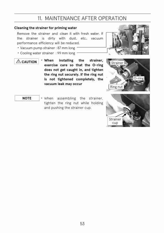
11. MAINTENANCE AFTER OPERATION
Cleaning the strainer for priming water Remove the strainer and clean it with fresh water. If the strainer is dirty with dust, etc., vacuum performance efficiency will be reduced. ・Vacuum pump strainer : 87 mm long ・Cooling water strainer : 99 mm long
・ When installing the strainer, exercise care so that the O-ring does not get caught in, and tighten the ring nut securely. If the ring nut is not tightened completely, the vacuum leak may occur
・ When assembling the strainer, tighten the ring nut while holding and pushing the strainer cup.
Strainer
O-ring
Ring nut
Strainer cup
NOTE
CAUTION

54
11. MAINTENANCE AFTER OPERATION
Charging battery
<Battery>
・ Read the safety instructions and/or warnings carefully before using or charging the batteries.
・ Hydrogen gas from the battery is explosive. ・ Keep battery away from flame and sparks. ・ Charge the battery in well ventilated area. Do not charge battery
in unventilated area.
・ Connecting battery cables, connect positive (+) lead first. ・ Disconnecting battery cables, disconnect negative (-) lead first.
・ Keep surface of the battery clean.
<Battery charger>
・ The battery capacity must be 12V-16 Ah/5h. ・ Do not connect a cigarette lighter to the battery charger socket.
Doing so may melt or burn out the socket due to overheating. ・ Hydrogen gas inside the battery may explode if something sparks. ・ Keep the battery away from flame and sparks. ・ Charge battery in well ventilated area.
・ Use an automatic battery charger. ・ Use a battery charger that has an overcharge prevention function. ・ Read the instruction manual of the battery charger before
charging a battery. ・ Automatic charger should be kept in a dry and well-ventilated
place.
NOTE
CAUTION
CAUTION
WARNING
WARNING

55
11. MAINTENANCE AFTER OPERATION
1. Be sure to charge the battery after each operation.
Battery charger plug socket location__
2. Turn off the power of the pump. (Turn off the main switch.)
3. Confirm that there is no dirt, no slack, no backlash of the terminal.
4. Plug the charging plug to the battery charger plug socket of pump.
5. Insert the power plug of the charger to an alternating current power source.
6. Confirm the battery charging status.
*Refer to the battery instruction manual.
7. Disconnect the battery charger plug from the socket when using or moving the pump.
・ If the main switch is on, the battery cannot be charged. ・ Pull out the battery charger plug from the socket when using or
moving the pump.
VF63AS-R
Main switch
VF53AS
OFF
Main switch
NOTE
Battery charger plug and socket
Battery charger

56
12. MAINTENANCE IN COLD CONDITION
Infuse anti-freezing fluid
・ If the temperature around the pump could be subzero, the inside of the pump can be frozen. In this case, the water pump or the vacuum pump may not be worked. And also the pump unit including engine and muffler may be damaged or broken.
・ In order to prevent internal corrosion and freeze damage by the water in the pump, drain all the water from the pump after each use.
・ After draining the water, put antifreeze fluid into the pump and vacuum pump.
Pump unit
1. When storing the pump, drain all the water from the pump. Open the pump drain valves, the muffler drain valve and the air valve for drainage, and completely drain the water from the pump.
2. Close the pump drain valves, the muffler drain valve. Install the suction port cap. (Keep the air valve for drainage opened.) Insert a plastic tube to the air valve (which is for assisting water drainage). Start the engine and turn on the auto priming switch. Turn the throttle to the "suction" position to run the vacuum pump for about 5 seconds to take the water off on the rotating part. Stop the engine.
3. Put the plastic tube into the antifreeze liquid, and also put a plastic tube which comes from the vacuum pump (through the lower-side cover) into the antifreeze liquid (180ml/0.048 gal(US) ~ 200ml/0.053gal(US) / undiluted solution) in a container.
Air valve Open
Suction port cap
Close
Open
Close
Open
Drain valve
Plastic tube
Antifreeze fluid
Air valve
CAUTION

57
12. MAINTENANCE IN COLD CONDITION
4. Start engine
- VF53AS - ・ Set the Auto-priming switch “ON” position.
・ Turn the throttle dial to the “Start” position.
・ Turn on the main switch. Start the engine by turning the key. Release the main switch immediately after the engine starts.
-VF63AS-R - ・ Press the main switch to run the engine.
・ Switch the priming water mode switch to the “Automatic”.
Start position
Suction position
Throttle dial
VF53AS
Auto-priming switch
ON START
Main switch
VF63AS-R
Main switch
Priming water mode switch

58
12. MAINTENANCE IN COLD CONDITION
5. Turn the throttle dial to the suction position, then the suction will start.
Keep running to suck up antifreeze until it stops automatically. The pump will stop automatically in about 30 second because of the water suction failure.
6. Stop the engine.
- VF53AS - ・Turn off the main switch.
- VF63AS-R - ・Press the stop switch to stop the engine.
・Press the main switch to turn off the power.
7. Close the air valve which is for assisting water drainage, and take the plastic tube off from the air valve.
Discharge valve
Pour antifreeze fluid into the seal area of the discharge valve.
To use a long nozzle container is helpful when pouring antifreeze fluid.
Discharge valve
VF63AS-R Suction position
Air valve
Close
VF53AS Suction position
VF63AS-R
Main switch
Stop switch
OFF
Main switch
VF53AS

59
13. USE OF ACCESSORY
Battery Battery performance deteriorates i n a low-temperature condition. Further, battery could be easier to freeze if the specific gravity is low.
・ Hydrogen gas from a battery is explosive. Keep a battery away from flame and sparks.
・ Hydrogen gas emitted from a battery will also cause severe burns to skin and damage
・ Charge a battery in well ventilated area. Do not charge a battery in an unventilated area.
・ Read the instructions attached to the battery carefully before use.
・ When charging batteries, be sure to use an automatic battery charger.
・ Use an automatic battery charger that matches the battery specifications. Use of a mismatched automatic battery charger may cause the battery to explode.
・ Keep the battery surface clean. ・ Battery life is normally 2~3 years even if a
battery is used properly. Replace with new battery every 2~3 years checking the deterioration of the charging performance.
・ When connecting battery cables, positive (+) lead shall be connected first. (When disconnecting battery, remove the negative (-) lead first.)
・ Battery electrolyte is very caustic acid, which will cause severe burns to your skin and damage to clothing.
Battery charger
・ Read the instruction manual of the battery charger. The instruction manual is packed with the charger.
・ Set the battery charger on a suitable noninflammable stand or fix on wall, not directly onto the ground.
CAUTION
WARNING
CAUTION

60
13. USE OF ACCESSORY
Pumping plate
・ In the case of using a fire pump without a nozzle as a feed water pump, such as pumping water out of a cellar, put the pumping plate* (which has holes) in between the discharge port adapter and the packing in order to prevent the overheating of the engine and the pump cavitation which may cause damages to the pump.
* Pumping plate is the standard accessory: Part No. 151-39045-1
・ Put the pumping plate as the figure shown above, so that pressure for cooling water in the pump is maintained at certain level. Then you can use the pump without a discharge nozzle.
Ball valve type discharge valve Screw down type discharge valve type
NOTE
CAUTION
Packing
Discharge port adaptor (Option)
Pumping plate
Discharge port adaptor (Option)
Packing Pumping plate
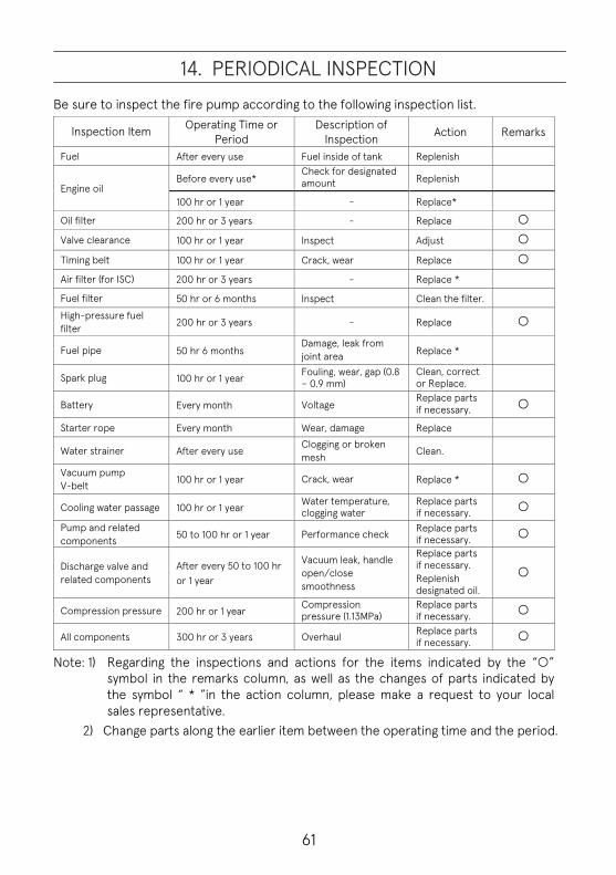
61
14. PERIODICAL INSPECTION
Be sure to inspect the fire pump according to the following inspection list.
Inspection Item Operating Time or Period
Description of Inspection Action Remarks
Fuel After every use Fuel inside of tank Replenish
Engine oil Before every use*
Check for designated amount Replenish
100 hr or 1 year - Replace*
Oil filter 200 hr or 3 years - Replace
Valve clearance 100 hr or 1 year Inspect Adjust
Timing belt 100 hr or 1 year Crack, wear Replace
Air filter (for ISC) 200 hr or 3 years - Replace *
Fuel filter 50 hr or 6 months Inspect Clean the filter.
High-pressure fuel filter 200 hr or 3 years - Replace
Fuel pipe 50 hr 6 months Damage, leak from joint area Replace *
Spark plug 100 hr or 1 year Fouling, wear, gap (0.8 – 0.9 mm)
Clean, correct or Replace.
Battery Every month Voltage Replace parts if necessary.
Starter rope Every month Wear, damage Replace
Water strainer After every use Clogging or broken mesh Clean.
Vacuum pump V-belt 100 hr or 1 year Crack, wear Replace *
Cooling water passage 100 hr or 1 year Water temperature, clogging water
Replace parts if necessary.
Pump and related components 50 to 100 hr or 1 year Performance check Replace parts
if necessary.
Discharge valve and related components
After every 50 to 100 hr or 1 year
Vacuum leak, handle open/close smoothness
Replace parts if necessary. Replenish designated oil.
Compression pressure 200 hr or 1 year Compression pressure (1.13MPa)
Replace parts if necessary.
All components 300 hr or 3 years Overhaul Replace parts if necessary.
Note: 1) Regarding the inspections and actions for the items indicated by the “ ” symbol in the remarks column, as well as the changes of parts indicated by the symbol “ * ”in the action column, please make a request to your local sales representative.
2) Change parts along the earlier item between the operating time and the period.

62
14. PERIODICAL INSPECTION
The following table shows the parts that are recommended to be changed periodically.
Parts Name Recommended Replacement
Frequency Problem Occurred
Spark plug 1 year Unable to start due to wear of electrode.
Fuel pipe 2 years Fuel leak due to deterioration. Battery 2 years Life expiration. Oil pipe 3 years Oil leak due to deterioration. Oil filter 3 years Overheating of engine. Air filter 3 years Engine revolution failure. Vacuum pump driving belt 3 years Slip due to wear. Timing belt 3 years Valve timing deviation.
Other rubbers 2 years Functional degradation due to deterioration.
Starter rope 3 years Breakage due to wear.
Fuel filter 3 years Unable to start due to clogging with dust or mixing of water.
Discharge reverse flow check valve (rubber) 3 years Functional degradation due to
wear and deterioration.
Mechanical seal 3 years Unable to suck water due to wear.
Vane for oil less vacuum pump 3 years Unable to suck water due to
wear.
Fuel tank 10 years Functional degradation due to corrosion.
Parts to be simultaneously changed during disassembly: ・ Gasket ・ O-ring
and the other parts which have damages should be changed.

63
15. SERVICE AND MAINTENANCE
General Servicing and maintenance of the fire pump must only be carried out by personnel who have professional related knowledge and who are familiar with the fire pump and regulations regarding safety and accident prevention.
Before starting maintenance work: ・ Stop the engine. ・ Place the pump on a level location. ・ Disconnect the negative terminal of the battery.
Safety devices
・ After safety or protective devices have been disassembled as part of servicing and maintenance work, immediately install them back to the original position after the maintenance. Make sure that they run normally without problems.
Genuine parts
When replacing parts as a part of servicing and maintenance of the fire pump, use only Tohatsu genuine parts. If genuine Tohatsu parts and accessories are not used, it may adversely affect the function and safety of the fire pump. Therefore, for safety reason, use only Tohatsu genuine parts. Tohatsu bears no responsibility for any personal injuries or equipment damages that may result from use of parts or accessories obtained from outside sources.
Environmental protection measures Dispose of oil, fuel, batteries, etc. according to relevant environmental laws in the region. Do not dump to nature or sewerage.
Waste When discarding parts, go waste in accordance with environmental laws in the region procedure.
CAUTION

64
15. SERVICE AND MAINTENANCE
Cowl removal and installation
Top cowl removal 1. Lift the latch up on the rear side and move the
cowl upward.
Remove the cowl from the latch at the front side of the pump.
2. Remove the cowl.
Top cowl installation
1. Put the cowl. Hook the upper cowl latch plate at the front inside of the cowl to the hook at the front side of the bottom cowl.
2. Attach the cowl firmly by pulling down the cowl latch on the rear side.
Latch Plate
Hook
Cowl latch
Cowl latch
Latch Plate

65
15. SERVICE AND MAINTENANCE
Vacuum pump strainer
Maintenance
・ Incorrect installation of the strainer may cause a vacuum leak. Be sure to install the strainer correctly.
Refer to “Chapter 11 MAINTENANCE AFTER OPERATION”
Wash the strainer with fresh water after use.
1. Remove the vacuum pump strainer. Turn the ring nut while pushing and holding the strainer cup.
Strainer length: 87mm
Remove the cooling water strainer. Turn the ring nut while pushing and holding the strainer cup.
Strainer length: 99mm
2. Wash the strainer and the strainer cup on each.
3. After the washing, assemble the strainer cups and strainers tightening with the ring nuts on each.
・ When installing a strainer, pay attention to the protrusion of the O-ring and install it correctly. Otherwise, a vacuum leak may occur.
Cooling water strainer (Cup)
Vacuum pump strainer (Case)
Strainer
Cooling water strainer
Vacuum pump strainer
Tighten
Loosen
NOTE
NOTE

66
15. SERVICE AND MAINTENANCE
Engine oil
Check the oil level Check the oil level before engine start. The correct engine oil level cannot be confirmed during the engine driving and just after driving. Need time (1 day) to check the level correctly.
* The engine oil stays in some parts inside the engine.
・ Confirm the filler cap closed tightly each time , whenever you check the oil level.
・ Check the oil level before each operation.
1. Place the pump in a horizontal location. 2. Check the oil level.
3. Refill the oil until about “Upper” level if the oil level is not enough.
・ 4-stroke engine oil: SAE 10W-30/40 of SF, SG, SH, SJ, SL and SM series of API classification
Vacuum pump V-belt
Check the V-belt every year or every 100 hours operating time.
V-belt size: LA-26
V-belt
Filler cap
Oil level
NOTE
CAUTION

67
15. SERVICE AND MAINTENANCE
Spark plug Check the spark plugs. 1. Remove the plug cap, and remove the spark
plug.
2. Clean the electrode of the spark plug using a wire brush or spark plug cleaner.
3. Check the spark plug for excessive carbon
deposits, electrode erosion and check the washer for damage.
4. Measure the spark plug gap. If the gap is out of
specification, replace the spark plug with the specified spark plug.
If necessary, adjust the gap to specification.
・ Spark plug gap : 0.8–0.9 mm ・ Usage limit : 1.2 mm ・ Spark plug : NGK DCPR6E
5. Assemble the spark plug as far as ⓐ by hand. Tighten the plug further to the specified torque using a plug wrench.(ⓑ)
・ Tightening torque : 18 N·m (13 Ib·ft) [1.8 kgf·m]
Spark plug
Washer Electrode Electrode
Washer
Spark plug gap

68
15. SERVICE AND MAINTENANCE
Battery
General safety information Follow the safety instructions on the battery. When charging batteries, highly explosive oxyhydrogen gas mixture is produced. Do not charge a battery in a poorly ventilated place. Do not smoke near the battery.
Injury caused with caustic substances of battery.
・ Always wear protective clothing. ・ Always wear protective gloves. ・ Always wear protective glasses. ・ Do not tip the battery, acid would
come out through the air vents.
Disposal 15 Disused batteries should be disposed according to local laws or regulations. After each operation of the battery, check the voltage. Replace the battery if necessary. When disconnect a battery, disconnect the negative (-) terminal of the battery cable first, then disconnect the positive terminal.
・ There is a risk of injury. ・ When handling the battery, be
sure to wear safety glasses and protective gloves.
DANGER
CAUTION

69
15. SERVICE AND MAINTENANCE
Electric equipment Only expert electricians or trained staff members should handle electrical equipment.
Be sure to disconnect battery cables before handling electrical equipment. Disconnect the negative (-) terminal first, disconnect the positive (+) terminal next.
Connecting battery cables, connect the positive (+) terminal first. After that, connect the negative (-) terminal next.
Use the fuse with the same current rating (ampere) as that of the installed fuse. Using a fuse that has excessively high resistance may result in electrical equipment failures.
Fuse
Security fuses are installed in electrical circuits used. Before replacing the fuse, isolate the cause of the short circuit, and take an appropriate action. After the appropriate action has been taken, replace the fuse with a new one. Prepare the spare fuse at all times for emergency.
Fuse box
Fuse
Spare Cap
Fuse

70
15. SERVICE AND MAINTENANCE
Suction performance and Vacuum leak check
・ Limit continuous operating time of the vacuum pump to 30 seconds or less.
・ Running the engine at vacuum pump operating speed continuously with no water for more than 30 seconds, may cause the engine overheating. If the engine overheats, wait until it cools down, or run the pump with pumping up water and discharg ing water to cool down the eng ine earl ier.
The water discharge operation allows the cooling water goes into the engine cooling line and circulates in the engine, and then the engine will be cooled down.
1. Cap the suction port with a suitable suction cap.
・ Prepare a suction port cap that is suitable for the suction coupling.
2. Confirm the drain valves and air valve are all closed.
Suction port cap
Air valve
Close
NOTE
CAUTION
Close
Open
Open
Drain valve
Close

71
15. SERVICE AND MAINTENANCE
3. Run the engine - VF53AS -
・ Turn on the Auto-priming switch. ・ Turn the throttle dial to the “Start” position.
・ Turn the main switch to the “ON” position.
- VF63AS-R - ・ Turn the throttle dial to “Low pressure (Start)”
position. ・ Press the main switch until the engine starts.
・ Extended operation of the starter motor will run the battery drain. Operate the starter motor for maximum 3 seconds. If the engine does not start, wait for 5 seconds before operating the starter motor again.
4. Turn the throttle dial to "Suction" position, then the
pump will start to suck up water automatically.
If suction water is not confirmed by the sensor in 30 seconds, the engine will stop automatically. Refer to ”Chapter 16 TROBLESHOOTING”. Then take the appropriate action and check the vacuum leak again.
VF53AS
Auto-priming switch
Throttle dial
Main switch
VF63AS-R
Main switch
Throttle dial
VF53AS
Suction position
Throttle dial
Main switch
VF63AS-R
Throttle dial Main switch
Suction position
NOTE

72
15. SERVICE AND MAINTENANCE
5. Check that the pressure gauge for suction indicates approximately -0.08MPa (-12psi).
6. Stop the engine, and keep it for about 30 second.
Check if the suction pressure is kept the same pressure. If the vacuum leak is found, isolate the cause by referring to “Chapter 16 TROUBLESHOOTING”. Then take the appropriate action and check the vacuum leak will not happen again.
7. Open the drain valves slowly to expose it to the atmosphere, and check that the pointer of the suction pressure gauge returns to “0”.
8. Close the drain valves again.
・ Before storing the fire pump, flush with fresh water to purge any debris from the pump. (Especially after using salt water, muddy water, contaminated water, etc.)
・ Rubber gaskets, O-rings, seals for the discharge and suction hose fitting wear: Worn rubber seals will cause water leaks, poor vacuum, etc. Frequent inspection of these items is mandatory.
Suction pressure gauge
Close Open
Open
Close Drain valve
NOTE

73
15. SERVICE AND MAINTENANCE
Water leak check 1. Attach a suction hose to the suction port.
2. Place the end of the hose into the water more than 30cm deep from the water surface.
3. Close the discharge valve(s) and drain valves.
4. Start the engine and suck up water. * In the case of manual operation, pull the priming
knob.
5. Operate the throttle dial to raise the pump pressure almost to 1MPa (145psi), and then check for water leaks from each part of the pump and the cooling water piping.
If a water leak is found, isolate the cause referring to “Chapter 16 TROUBLESHOOTING”. Then, take the appropriate action and check the vacuum leak will not happen again.
Priming knob
(Manual operation)
Close
Close
Ball valve
Close Open
Open
Close Drain valve

74
16. TROUBLESHOOTING
Typical causes of engine troubles are listed in the following tables.
Trouble
Cause
Battery charging failure Starter m
otor does not work
Engine start failure Engine stum
ble or stall Rough idling Idling is too high Poor acceleration Engine over- revolution Engine overheat Engine seizing Vacuum
pressure defective Air leaking W
ater suction failure
Insufficient w
ater discharge
Floodlight, Gauge lam
p, Hour m
eter, Warning lam
p do not w
ork
Warning lam
p flashing
Action C
aused by suction C
aused by pump unit
Caused by playpipe
Caused by engine unit
Fuel and lubrication
Fuel shortage ● ● ● ● Refuel.
Deterioration of fuel ● ● ● ● ● ●
Replace with new fuel.
Fuel tank air vent clogging ● ● ● ● ● ● Clean the clogging.
Fuel filter clogging ● ● ● ● ● ● Clean the clogging.
Fuel pump failure ● ● ● ● ● ● Replace.
Injector failure ● ● ● ● ● ● Replace.
Fuel pipe kink or snap ● ● ● ● ● ●
Fix routing of the pipe.
Throttle dial at other than “start” position
● Turn dial to “start” position.
Oil filter clogging
●
●
●
●
Replace oil filter. (Do not fill it up with the different brand of oil.)

75
16. TROUBLESHOOTING
Trouble
Cause
Battery charging failure Starter m
otor does not work
Engine start failure Engine stum
ble or stall Rough idling Idling is too high Poor acceleration Engine over- revolution Engine overheat Engine seizing Vacuum
pressure defective Air leaking W
ater suction failure
Insufficient w
ater discharge
Floodlight, Gauge lam
p, Hour m
eter, Warning lam
p do not w
ork
Warning lam
p flashing
Action C
aused by suction C
aused by pump unit
Caused by playpipe
Caused by engine unit
Electrical
Spark plug cap comes off ● ● ● ● ● Plug in surely.
Use of unspecified spark plug ● ● ● ● ● ● ●
Replace with specified spark plug.
Spark plug fouling (No spark or weak spark)
● ● ● ● ● Clean or replace with specified spark plug.
ECU and/or Sensors failure ● ● ● ● ● ● ● ● ●
Check wire connection. Plug in surely. If necessary replace.
Battery loose connection, terminal corrosion or expired
● ● ●
Clean terminal and/ or tighten a terminal screw. If necessary replace.
Battery charger defective ●
Check 7.5A fuse and/ or Battery charger. Replace if necessary.

76
16. TROUBLESHOOTING
Trouble
Cause
Battery charging failure Starter m
otor does not work
Engine start failure Engine stum
ble or stall Rough idling Idling is too high Poor acceleration Engine over- revolution Engine overheat Engine seizing Vacuum
pressure defective Air leaking W
ater suction failure
Insufficient w
ater discharge
Floodlight, Gauge lam
p, Hour m
eter, Warning lam
p do not w
ork
Warning lam
p flashing
Action C
aused by suction C
aused by pump unit
Caused by playpipe
Caused by engine unit
Electrical
15A fuse blown ● ●
Replace with spare fuse. When the blowout of the fuse happens repeatedly, check a cause.
15A: Battery cable reverse connection, Operation panel components.
Starter solenoid VP solenoid*
7.5A: charging connector. Floodlight connector. 2A:CPU*
7.5A fuse blown ●
2A fuse blown * ●
Starter motor defective ●
Check terminals, cords and screws. Replace parts if necessary.
Control panel defective ● ● ●
Check input of starter solenoid. (Equal to control panel output.) Replace parts if necessary.
*Only for VF63AS-R

77
16. TROUBLESHOOTING
Trouble
Cause
Battery charging failure Starter m
otor does not work
Engine start failure Engine stum
ble or stall Rough idling Idling is too high Poor acceleration Engine over- revolution Engine overheat Engine seizing Vacuum
pressure defective Air leaking W
ater suction failure
Insufficient w
ater discharge
Floodlight, Gauge lam
p, Hour m
eter, Warning lam
p do not w
ork
Warning lam
p flashing
Action C
aused by suction C
aused by pump unit
Caused by playpipe
Caused by engine unit
Com
pression
Piston, piston ring or cylinder worn excessively.
● ● ● ● ● ● Correct or replace.
Carbon deposition in the combustion chamber
● ● ● ● Clean out.
Suction
Suction height too high or length too long
● Place the pump nearer and/or lower position.
Suction hose end is not in water ● ● ● ●
Put the end of suction hose below 30cm from the surface of water.
Suction hose coupling loose or gasket defective
● ● ● ●
Clean out a gasket and tighten securely. Replace a gasket if necessary.
Suction hose strainer clogged with dead leaf or waste etc.
● ● Clean out.
Suction hose cracking or Lining peeling off
● ● ● ● Repair or replace.
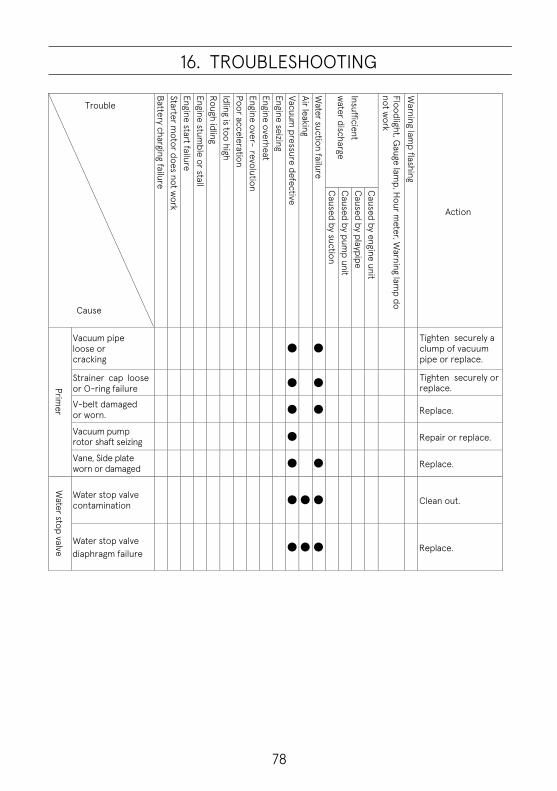
78
16. TROUBLESHOOTING
Trouble
Cause
Battery charging failure Starter m
otor does not work
Engine start failure Engine stum
ble or stall Rough idling Idling is too high Poor acceleration Engine over- revolution Engine overheat Engine seizing Vacuum
pressure defective Air leaking W
ater suction failure
Insufficient w
ater discharge
Floodlight, Gauge lam
p, Hour m
eter, Warning lam
p do not w
ork
Warning lam
p flashing
Action C
aused by suction C
aused by pump unit
Caused by playpipe
Caused by engine unit
Primer
Vacuum pipe loose or cracking
● ●
Tighten securely a clump of vacuum pipe or replace.
Strainer cap loose or O-ring failure ● ●
Tighten securely or replace.
V-belt damaged or worn. ● ● Replace.
Vacuum pump rotor shaft seizing ● Repair or replace.
Vane, Side plate worn or damaged ●
●
Replace.
Water stop valve
Water stop valve contamination ● ● ●
Clean out.
Water stop valve diaphragm failure ● ● ●
Replace.

79
16. TROUBLESHOOTING
Trouble
Cause
Battery charging failure Starter m
otor does not work
Engine start failure Engine stum
ble or stall Rough idling Idling is too high Poor acceleration Engine over- revolution Engine overheat Engine seizing Vacuum
pressure defective Air leaking W
ater suction failure
Insufficient w
ater discharge
Floodlight, Gauge lam
p, Hour m
eter, Warning lam
p do not w
ork
Warning lam
p flashing
Action
Caused by suction
Caused by pum
p unit C
aused by playpipe C
aused by engine unit
Pump
Drain valves are not closed ● ● ● Close securely.
Suction port strainer clogged with dead leaf or waste etc.
● ●
Clean out.
Discharge valve imperfect open ● ● Open securely.
Gauge pipe connector loose or gasket defective
● ● ● Tighten securely. Replace a gasket if necessary.
Pump cover bolts loose ● ● ● ● Tighten securely.
Pump cover O-ring degradation ● ●
Clean out or replace.
Impeller or Guide vane caught a stone or damaged
● ● Clean or replace.
Mechanical seal damaged ● ● Replace.
Nozzles
Discharge nozzle too large ● ● ●
Change a nozzle for suitable size or incorporate safety nozzle.
Spray nozzle clogged
● Clean out.
Governor
Governor adjustment out of specified range
● ● ● Readjust it securely.
Governor link disconnected ● ● ● ● ● ● ● ● Attach it securely.

80
17. APPENDIX
Tightening torque specifications
M3 M4 M5 M6 M8 M10 Standard Bolt
N·m 0.7 1.6 3 6 13 27 lb·ft 0.5 1.2 2 4 9 20
kgf·m 0.07 0.16 0.3 0.6 1.3 2.7 Heat Treated Bolt
N·m - - -
9 24 47 lb·ft 7 17 34
kgf·m 0.9 2.4 4.7

81
18. TOOL AND STANDARD ACCESSORY
Standard accessory
Description Quantity
Tool kit 1 Tool kit bag 1 Plug wrench 1 Handle of plug wrench 1 Spark plug (DCPR6E) 1 Pumping plate 1 Fuse *15A 1 Fuse *7.5A 1 Fuse *2A(VF63AS-R) 1 Vinyl pipe 1 Auto battery charger 1
*Spare fuses are attached in the fuse box.
Optional parts
Description Description Vinyl cover Operation light assy Suction strainer φ75 Fuel tank complete Search light(Floodlight) Primer bulb assy Bracket Anti-freeze kit Adjusting screw Tool box Tripod Ball valve
Special tool
Description Description Puller Piston slider Puller impeller Bevel gear nut socket Flywheel puller kit Crankshaft holder Spring pin tool A Test mode connector Spring pin tool B Diagnostic tool kit Friction measuring tool
Fuse box
VF63AS-R VF53AS

LEVE
LC
ON
VER
SIO
NU
NIT
BLAC
K
SWIT
CH
SUC
TIO
NM
OD
ES2
ON
:AU
TOO
FF:M
ANU
AL
NEE
DM
ASKI
NG
WH
ITE
WAR
NIN
GLI
GH
T1
WAR
NIN
GLI
GH
T2
OVE
RH
EAT
/ SU
CTI
ON
WA
TER
FAI
LUR
E / O
THER
S
DR
IVIN
G L
IGH
T R
ELAY
Arro
win
dica
tes
the
dire
ctio
nof
the
curre
nt
RED
INST
RU
MEN
TLA
MP
OVE
RH
EAT
/SU
CTI
ON
WAT
ERFA
ILU
RE
MAP
/WAT
ERTE
MPE
RAT
UR
ESE
NSO
R
DR
IVIN
GLI
GH
TR
ELAY
INJ/PUMPPOWERSUPPLYEXCITERCOIL(H)
DRIVINGLIGHTRELAY
#1PULSERCOIL(-)
SENSORPOWERSUPPLYINJ/PUMPCOIL(V)INJ/PUMPCOIL(U)INJ/PUMPCOIL(W)
EXCITERCOIL(M)EXCITERCOIL(L)
#1IGCOIL#2IGCOIL#3IGCOILPOWERGND
#1PULSERCOIL(+)#2PULSERCOIL(+)
SENSORGND
INJPOWERSUPPLY/EXTERNALSUPPLYLED2OVERHEAT/SUCTIONWATERFAILURE/OTHERS(B16)
P8382
19. WIRING DIAGRAM VF53AS VF63AS

PULS
ARC
OIL
PULS
ARC
OIL
DR
IVIN
GLI
GH
TR
ELA
Y
CPUCIRCUIT
CONSTANTVOLTAGECIRCUIT
SIN
GLE
/REL
AYSW
ITC
H
SIN
GLE
/REL
AYSW
ITC
H
POW
ERO
N STAR
T
STAR
T
THR
OTT
LEM
OTO
R
MO
TOR
POTE
NTI
OM
ETER
MO
TOR
LIM
ITSW
ITC
H
THR
OTT
LED
IAL
DIA
LPO
TEN
TIO
MET
ER
DIA
LLI
MIT
SWIT
CH
SUC
TIO
NSE
NSO
R
PRES
SUR
ESE
NSO
R
ACTU
ATO
RPO
WER
SUPP
LY
HYD
RAU
LIC
/IN
TER
RU
PT
TEST
MO
DE
POW
ERSU
PPLY
TEST
MO
DE
CO
NN
ECTO
R
VF63ASR
83
19. WIRING DIAGRAM

OWNER’S MANUAL
VF53ASVF63AS-R PORTABLEFIRE PUMPNo.003-12076-1
5-4, Azusawa 3-Chome, Itabashi-KuTokyo 174-0051, JapanPhone: +81-3-3966-3137
VF53ASVF63AS-R PORTABLEFIRE PUMPNo.003-12076-1
OWNER’S MANUAL
OWNER’S M
ANUAL
VF53AS / VF63AS-R N
o.003-12076-1
⑩ _VF53AS