Embed Size (px)
Citation preview
Rev. 2/26/2018 VAN-J, MANUAL
Copyright 2017 Vestil Manufacturing Corp. Page 1 of 11
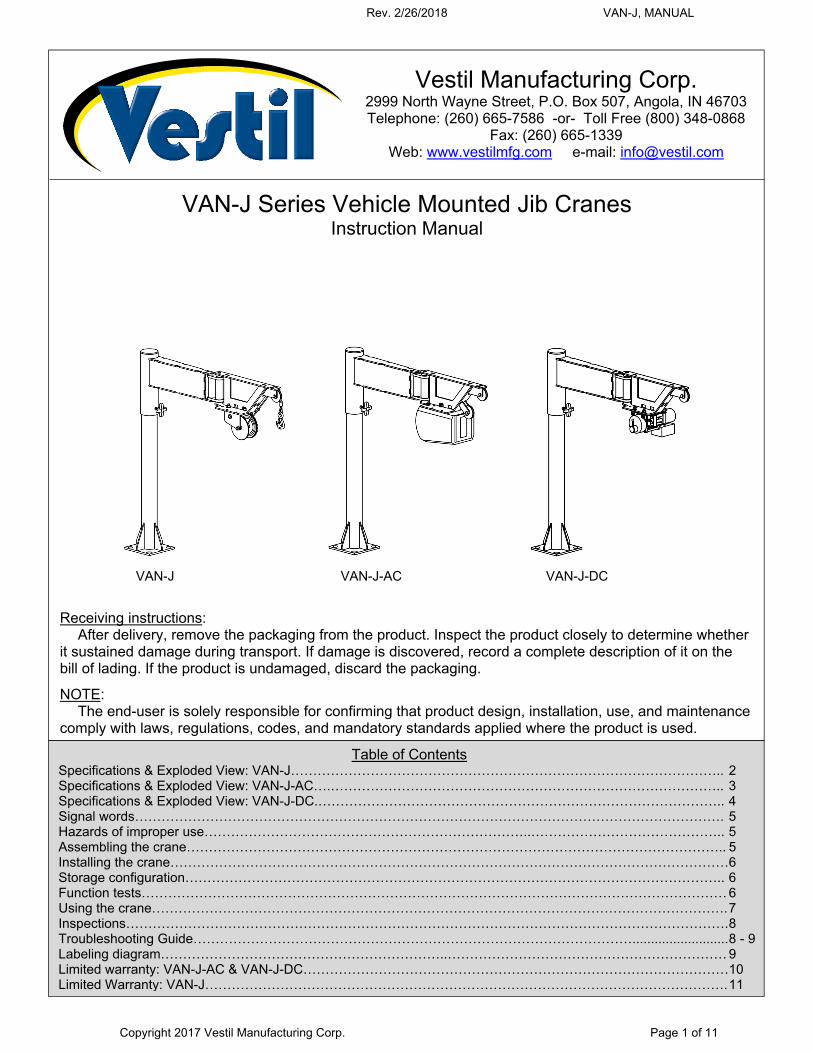
VAN-J Series Vehicle Mounted Jib Cranes
Instruction Manual
Receiving instructions: After delivery, remove the packaging from the product. Inspect the product closely to determine whether it sustained damage during transport. If damage is discovered, record a complete description of it on the bill of lading. If the product is undamaged, discard the packaging.
NOTE: The end-user is solely responsible for confirming that product design, installation, use, and maintenance comply with laws, regulations, codes, and mandatory standards applied where the product is used.
Table of Contents Specifications & Exploded View: VAN-J…………………………………………………………………………………….. 2 Specifications & Exploded View: VAN-J-AC….…………………………………………………………………………….. 3 Specifications & Exploded View: VAN-J-DC.……………………………………………………………………………….. 4 Signal words……………………………………………………………………………………………………………………. 5 Hazards of improper use………………………………………………………………..…………………………………….. 5 Assembling the crane………………………………………………………………………………………………………….. 5 Installing the crane………………………………………………………………………………………………………………6 Storage configuration………………………………………………………………………………………………………….. 6 Function tests…………………………………………………………………………………………………………………… 6 Using the crane…………………………………………………………………………………………………………………. 7 Inspections………………………………………………………………………………………………………………………. 8 Troubleshooting Guide……………………………………………………………………………………….......................... 8 - 9 Labeling diagram………………………………………………………..……………………………………………………… 9 Limited warranty: VAN-J-AC & VAN-J-DC……………………………………………………………………………………10 Limited Warranty: VAN-J………………………………………………………………………………………………………. 11
Vestil Manufacturing Corp. 2999 North Wayne Street, P.O. Box 507, Angola, IN 46703 Telephone: (260) 665-7586 -or- Toll Free (800) 348-0868
Fax: (260) 665-1339 Web: www.vestilmfg.com e-mail: [email protected] U
VAN-J VAN-J-AC VAN-J-DC
Rev. 2/26/2018 VAN-J, MANUAL
Copyright 2017 Vestil Manufacturing Corp. Page 2 of 11
Specifications: Crane dimensions, capacity, and net weight appear in the diagrams and tables below.
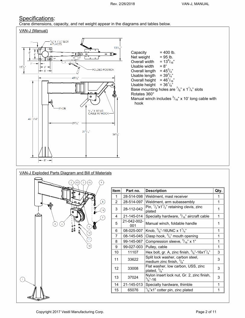
VAN-J (Manual)
Capacity = 400 lb. Net weight = 95 lb. Overall width = 139/16” Usable width = 8” Overall length = 453/4” Usable length = 393/4” Overall height = 461/16” Usable height = 361/8” Base mounting holes are 7/8” x 11/4” slots Rotates 360° Manual winch includes 3/16” x 10’ long cable with
hook
VAN-J Exploded Parts Diagram and Bill of Materials
Item Part no. Description Qty.
1 28-514-098 Weldment, mast receiver 1
2 28-514-097 Weldment, arm subassembly 1
3 28-112-042 Pin, 1/2”x11/2” retaining clevis, zinc plated
1
4 21-145-014 Specialty hardware, 3/16” aircraft cable 1
5 21-042-002-
001 Manual winch, foldable handle 1
6 08-025-007 Knob, 3/8”-16UNC x 11/4” 1
7 08-145-045 Clasp hook, 3/4” mouth opening 1
8 99-145-067 Compression sleeve, 3/16” x 1” 1
9 99-027-003 Pulley, cable 1
10 11107 Hex bolt, gr. A, zinc finish, 3/8”-16x11/4” 3
11 33622 Split lock washer, carbon steel, medium zinc finish, 3/8”
3
12 33008 Flat washer, low carbon, USS, zinc plated, 3/8”
3
13 37024 Nylon insert lock nut, Gr. 2, zinc finish, 3/8”-16
3
14 21-145-013 Specialty hardware, thimble 1
15 65076 1/8”x1” cotter pin, zinc plated 1
Rev. 2/26/2018 VAN-J, MANUAL
Copyright 2017 Vestil Manufacturing Corp. Page 3 of 11
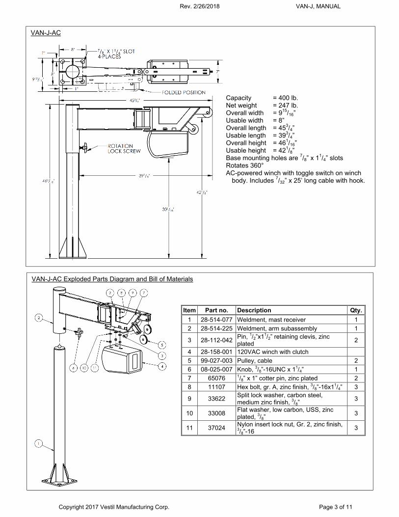
VAN-J-AC
Capacity = 400 lb. Net weight = 247 lb. Overall width = 915/16” Usable width = 8” Overall length = 453/4” Usable length = 393/4” Overall height = 461/16” Usable height = 421/8” Base mounting holes are 7/8” x 11/4” slots Rotates 360° AC-powered winch with toggle switch on winch
body. Includes 7/32” x 25’ long cable with hook.
VAN-J-AC Exploded Parts Diagram and Bill of Materials
Item Part no. Description Qty.
1 28-514-077 Weldment, mast receiver 1
2 28-514-225 Weldment, arm subassembly 1
3 28-112-042 Pin, 1/2”x11/2” retaining clevis, zinc plated
2
4 28-158-001 120VAC winch with clutch
5 99-027-003 Pulley, cable 2
6 08-025-007 Knob, 3/8”-16UNC x 11/4” 1
7 65076 1/8” x 1” cotter pin, zinc plated 2
8 11107 Hex bolt, gr. A, zinc finish, 3/8”-16x11/4” 3
9 33622 Split lock washer, carbon steel, medium zinc finish, 3/8”
3
10 33008 Flat washer, low carbon, USS, zinc plated, 3/8”
3
11 37024 Nylon insert lock nut, Gr. 2, zinc finish, 3/8”-16
3
Rev. 2/26/2018 VAN-J, MANUAL
Copyright 2017 Vestil Manufacturing Corp. Page 4 of 11
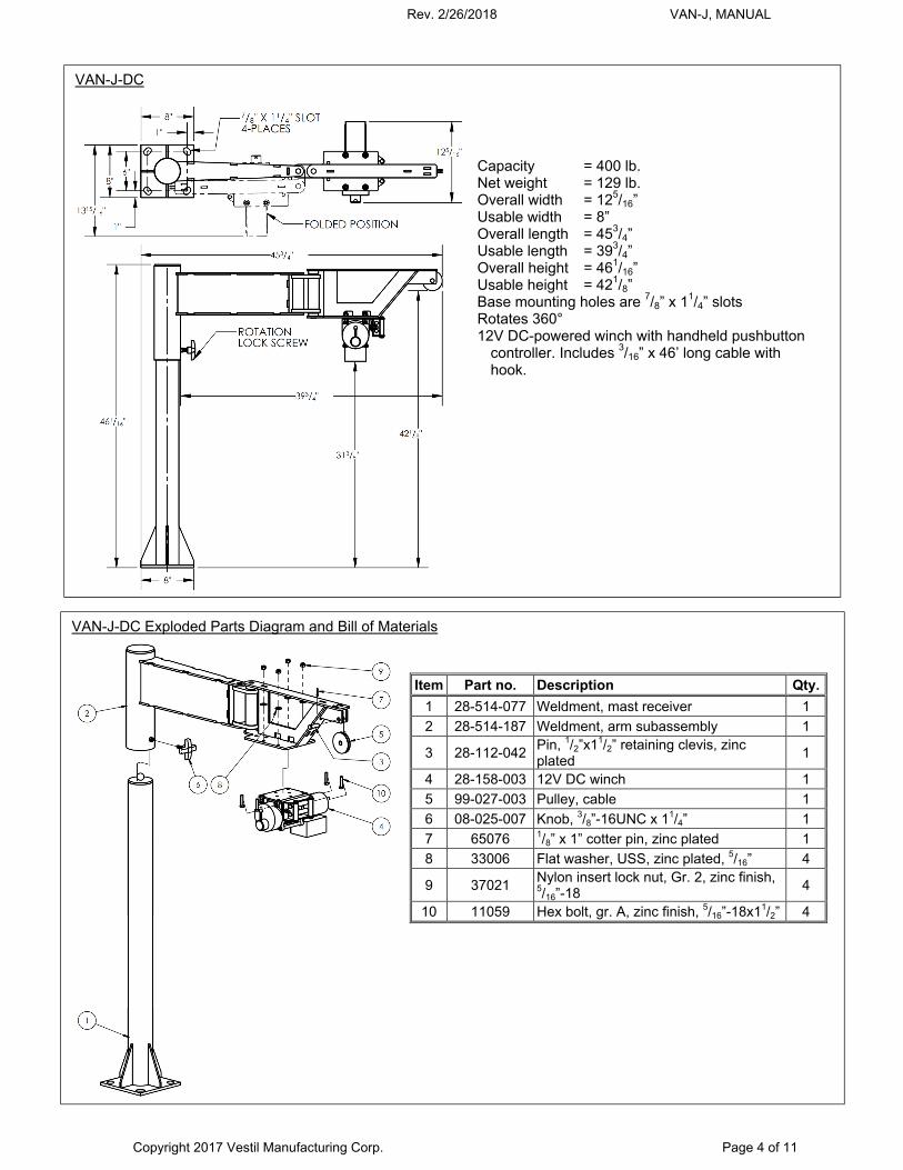
VAN-J-DC
Capacity = 400 lb. Net weight = 129 lb. Overall width = 125/16” Usable width = 8” Overall length = 453/4” Usable length = 393/4” Overall height = 461/16” Usable height = 421/8” Base mounting holes are 7/8” x 11/4” slots Rotates 360° 12V DC-powered winch with handheld pushbutton
controller. Includes 3/16” x 46’ long cable with hook.
VAN-J-DC Exploded Parts Diagram and Bill of Materials
Item Part no. Description Qty.
1 28-514-077 Weldment, mast receiver 1
2 28-514-187 Weldment, arm subassembly 1
3 28-112-042 Pin, 1/2”x11/2” retaining clevis, zinc plated
1
4 28-158-003 12V DC winch 1
5 99-027-003 Pulley, cable 1
6 08-025-007 Knob, 3/8”-16UNC x 11/4” 1
7 65076 1/8” x 1” cotter pin, zinc plated 1
8 33006 Flat washer, USS, zinc plated, 5/16” 4
9 37021 Nylon insert lock nut, Gr. 2, zinc finish, 5/16”-18
4
10 11059 Hex bolt, gr. A, zinc finish, 5/16”-18x11/2” 4
Rev. 2/26/2018 VAN-J, MANUAL
Copyright 2017 Vestil Manufacturing Corp. Page 5 of 11
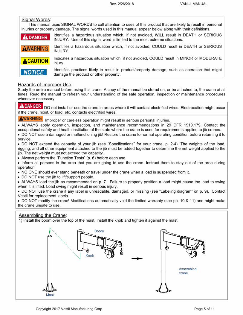
Signal Words: This manual uses SIGNAL WORDS to call attention to uses of this product that are likely to result in personal
injuries or property damage. The signal words used in this manual appear below along with their definitions.
Identifies a hazardous situation which, if not avoided, WILL result in DEATH or SERIOUS INJURY. Use of this signal word is limited to the most extreme situations.
Identifies a hazardous situation which, if not avoided, COULD result in DEATH or SERIOUS INJURY.
Indicates a hazardous situation which, if not avoided, COULD result in MINOR or MODERATE injury.
Identifies practices likely to result in product/property damage, such as operation that might damage the product or other property.
Hazards of Improper Use: Study the entire manual before using this crane. A copy of the manual be stored on, or be attached to, the crane at all times. Read the manual to refresh your understanding of the safe operation, inspection or maintenance procedures whenever necessary.
DO not install or use the crane in areas where it will contact electrified wires. Electrocution might occur if the crane, hoist, or load, etc. contacts electrified wires.
Improper or careless operation might result in serious personal injuries. ALWAYS apply operation, inspection, and maintenance recommendations in 29 CFR 1910.179. Contact the occupational safety and health institution of the state where the crane is used for requirements applied to jib cranes. DO NOT use a damaged or malfunctioning jib! Restore the crane to normal operating condition before returning it to service. DO NOT exceed the capacity of your jib (see “Specifications” for your crane, p. 2-4). The weights of the load, rigging, and all other equipment attached to the jib must be added together to determine the net weight applied to the jib. The net weight must not exceed the capacity. Always perform the “Function Tests” (p. 6) before each use. Inform all persons in the area that you are going to use the crane. Instruct them to stay out of the area during operation. NO ONE should ever stand beneath or travel under the crane when a load is suspended from it. DO NOT use the jib to lift/support people. ALWAYS load the jib as recommended on p. 7. Failure to properly position a load might cause the load to swing when it is lifted. Load swing might result in serious injury. DO NOT use the crane if any label is unreadable, damaged, or missing (see “Labeling diagram” on p. 9). Contact Vestil for replacement labels. DO NOT modify the crane! Modifications automatically void the limited warranty (see pp. 10 & 11) and might make the crane unsafe to use.
Assembling the Crane: 1) Install the boom over the top of the mast. Install the knob and tighten it against the mast.
Mast
Boom
Assembled crane
Knob
Rev. 2/26/2018 VAN-J, MANUAL
Copyright 2017 Vestil Manufacturing Corp. Page 6 of 11
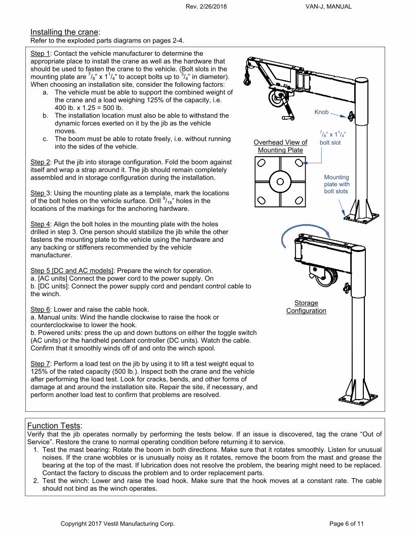
Installing the crane: Refer to the exploded parts diagrams on pages 2-4.
Step 1: Contact the vehicle manufacturer to determine the appropriate place to install the crane as well as the hardware that should be used to fasten the crane to the vehicle. (Bolt slots in the mounting plate are 7/8” x 11/4” to accept bolts up to 3/4” in diameter). When choosing an installation site, consider the following factors:
a. The vehicle must be able to support the combined weight ofthe crane and a load weighing 125% of the capacity, i.e.400 lb. x 1.25 = 500 lb.
b. The installation location must also be able to withstand thedynamic forces exerted on it by the jib as the vehiclemoves.
c. The boom must be able to rotate freely, i.e. without runninginto the sides of the vehicle.
Step 2: Put the jib into storage configuration. Fold the boom against itself and wrap a strap around it. The jib should remain completely assembled and in storage configuration during the installation.
Step 3: Using the mounting plate as a template, mark the locations of the bolt holes on the vehicle surface. Drill 9/16” holes in the locations of the markings for the anchoring hardware.
Step 4: Align the bolt holes in the mounting plate with the holes drilled in step 3. One person should stabilize the jib while the other fastens the mounting plate to the vehicle using the hardware and any backing or stiffeners recommended by the vehicle manufacturer.
Step 5 [DC and AC models]: Prepare the winch for operation. a. [AC units] Connect the power cord to the power supply. Onb. [DC units]: Connect the power supply cord and pendant control cable tothe winch.
Step 6: Lower and raise the cable hook. a. Manual units: Wind the handle clockwise to raise the hook orcounterclockwise to lower the hook. b. Powered units: press the up and down buttons on either the toggle switch(AC units) or the handheld pendant controller (DC units). Watch the cable. Confirm that it smoothly winds off of and onto the winch spool.
Step 7: Perform a load test on the jib by using it to lift a test weight equal to 125% of the rated capacity (500 lb.). Inspect both the crane and the vehicle after performing the load test. Look for cracks, bends, and other forms of damage at and around the installation site. Repair the site, if necessary, and perform another load test to confirm that problems are resolved.
Boom
Mast receiver
Angle adjustment pin
Function Tests:Verify that the jib operates normally by performing the tests below. If an issue is discovered, tag the crane “Out of Service”. Restore the crane to normal operating condition before returning it to service.
1. Test the mast bearing: Rotate the boom in both directions. Make sure that it rotates smoothly. Listen for unusualnoises. If the crane wobbles or is unusually noisy as it rotates, remove the boom from the mast and grease thebearing at the top of the mast. If lubrication does not resolve the problem, the bearing might need to be replaced.Contact the factory to discuss the problem and to order replacement parts.
2. Test the winch: Lower and raise the load hook. Make sure that the hook moves at a constant rate. The cableshould not bind as the winch operates.
Mounting plate with bolt slots
Overhead View of Mounting Plate
7/8” x 11/4” bolt slot
Knob
Storage Configuration
Rev. 2/26/2018 VAN-J, MANUAL
Copyright 2017 Vestil Manufacturing Corp. Page 7 of 11
Using the crane: To properly operate the crane, apply the following steps.
1. Connect the power cord to the power supply. a. AC units: connect to a properly grounded, GFCI-protected, 115V outlet. b. DC units: make sure battery connections are secure.
2. Apply appropriate rigging to the load. 3. Adjust the length and angle of the boom as your application requires. Consult the appropriate table on page 2 to
make sure that the load does not exceed the capacity of the crane in its present configuration. 4. If your crane has a manual winch, stand on the same side of the crane as the winch handle. Turn the handle
clockwise to lower the hook. If your winch is equipped with a powered winch, then it is electronically controlled. Both AC and DC-powered winches utilize a constant pressure (“dead man”) pushbutton controller. Press the DOWN button on the handheld controller. The winch will operate only while a control button is pressed. Releasing the button causes the winch to stop and the hook will maintain its position.
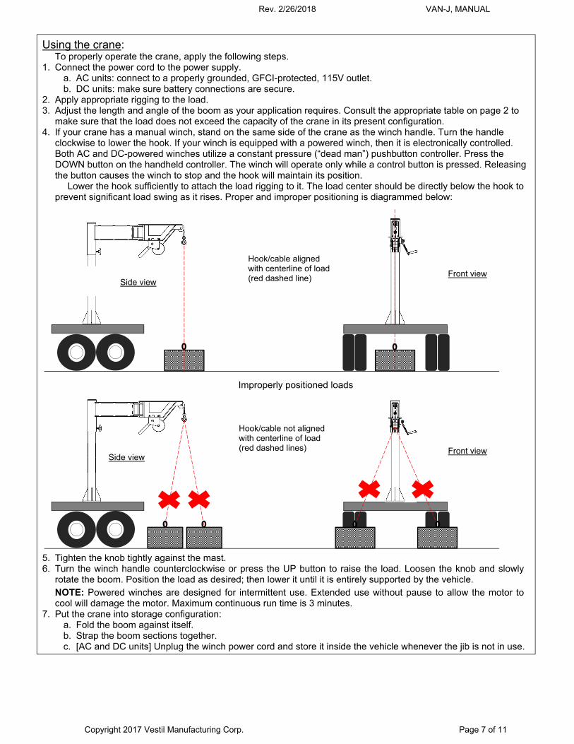
Lower the hook sufficiently to attach the load rigging to it. The load center should be directly below the hook to prevent significant load swing as it rises. Proper and improper positioning is diagrammed below:
Improperly positioned loads
5. Tighten the knob tightly against the mast. 6. Turn the winch handle counterclockwise or press the UP button to raise the load. Loosen the knob and slowly
rotate the boom. Position the load as desired; then lower it until it is entirely supported by the vehicle.
NOTE: Powered winches are designed for intermittent use. Extended use without pause to allow the motor to cool will damage the motor. Maximum continuous run time is 3 minutes.
7. Put the crane into storage configuration: a. Fold the boom against itself. b. Strap the boom sections together. c. [AC and DC units] Unplug the winch power cord and store it inside the vehicle whenever the jib is not in use.
Side view Front view
Hook/cable aligned with centerline of load (red dashed line)
Hook/cable not aligned with centerline of load (red dashed lines)
Side view Front view
1
Rev. 2/26/2018 VAN-J, MANUAL
Copyright 2017 Vestil Manufacturing Corp. Page 8 of 11
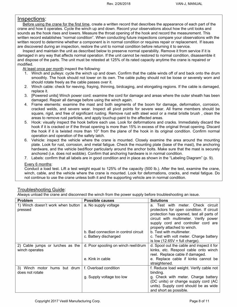
Inspections: Before using the crane for the first time, create a written record that describes the appearance of each part of the
crane and how it operates. Cycle the winch up and down. Record your observations about how the unit looks and sounds as the hook rises and lowers. Measure the throat opening of the hook and record the measurement. This written record establishes “normal condition”. When conducting future inspections compare your observations with the written record to determine whether a component is in normal condition or requires repair or replacement. If issues are discovered during an inspection, restore the unit to normal condition before returning it to service.
Inspect and maintain the unit as described below to preserve normal operability. Remove it from service if it is damaged in any way that affects normal operation. If the unit cannot be restored to normal condition, disassemble it and dispose of the parts. The unit must be retested at 125% of its rated capacity anytime the crane is repaired or modified.
At least once per month inspect the following: 1. Winch and pulleys: cycle the winch up and down. Confirm that the cable winds off of and back onto the drum
smoothly. The hook should not lower on its own. The cable pulley should not be loose or severely worn and should rotate freely as the cable passes over it.
2. Winch cable: check for reeving, fraying, thinning, birdcaging, and elongating regions. If the cable is damaged, replace it.
3. [Powered units] Winch power cord: examine the cord for damage and areas where the outer sheath has been damaged. Repair all damage before using the winch again.
4. Frame elements: examine the mast and both segments of the boom for damage, deformation, corrosion, cracked welds, and severe wear. Inspect all pivot points for severe wear. All frame members should be square, rigid, and free of significant rusting. Remove rust with steel wool or a metal bristle brush , clean the areas to remove rust particles, and apply touchup paint to the affected areas.
5. Hook: visually inspect the hook before each use. Look for deformations and cracks. Immediately discard the hook if it is cracked or if the throat opening is more than 15% in excess of the original throat opening. Discard the hook if it is twisted more than 10° from the plane of the hook in its original condition. Confirm normal operation and operation of the safety latch.
6. Vehicle: inspect the vehicle where the crane is mounted. Closely examine the area around the mounting plate. Look for rust, corrosion, and metal fatigue. Check the mounting plate (base of the mast), the anchoring hardware, and the vehicle bed/floor particularly around the anchor bolts. Make sure that the mast is securely anchored (i.e. does not wobble). Confirm that anchoring hardware is in normal condition.
7. Labels: confirm that all labels are in good condition and in place as shown in the “Labeling Diagram” (p. 9).
Every 6 months: Conduct a load test. Lift a test weight equal to 125% of the capacity (500 lb.). After the test, examine the crane, winch, cable, and the vehicle where the crane is mounted. Look for deformations, cracks, and metal fatigue. Do not continue to use the crane unless both it and the supporting vehicle are in normal condition.
Troubleshooting Guide: Always unload the crane and disconnect the winch from the power supply before troubleshooting an issue.
Problem Possible causes Solutions 1) Winch doesn’t work when button pressed
a. No supply voltage b. Bad connection in control circuit c. Battery discharged
a. Test with meter. Check circuit protectors for open condition. If circuit protection has opened, test all parts of circuit with multimeter. Verify power supply cord and controller cord are properly attached to winch. b. Test with multimeter. c. Test with volt meter. Charge battery is low (12.65V = full charge).
2) Cable jumps or lurches as the winch operates
d. Poor spooling on winch reel/drum e. Kink in cable
d. Spool out the cable and inspect it for kinks, etc. Respool cable onto winch reel. Replace cable if damaged. e. Replace cable if kinks cannot be straightened.
3) Winch motor hums but drum does not rotate
f. Overload condition g. Supply voltage too low
f. Reduce load weight. Verify cable not binding. g. Check with meter. Charge battery (DC units) or change supply cord (AC units). Supply cord should be as wide and short as possible.
Rev. 2/26/2018 VAN-J, MANUAL
Copyright 2017 Vestil Manufacturing Corp. Page 9 of 11
4) Mast does not rotate without great effort
h. Knobs tightened. i. Bearing overly worn.
h. Loosen knobs. i. Remove mast from mast receiver. Inspect bearing. Replace bearing if severely worn.
5) Personnel receive electric shocks when touching the jib or vehicle when winch in use.
j. Operating winch in wet conditions k. Winch wiring problem.
j. Allow winch to dry completely before using it again. k. Check winch electrical circuit including ground.
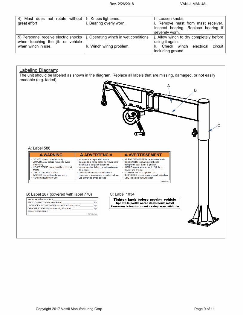
Labeling Diagram: The unit should be labeled as shown in the diagram. Replace all labels that are missing, damaged, or not easily readable (e.g. faded).
A
B
C
B: Label 287 (covered with label 770)
C: Label 1034
A: Label 586
Rev. 2/26/2018 VAN-J, MANUAL
Copyright 2017 Vestil Manufacturing Corp. Page 10 of 11
10/
LIMITED WARRANTY: VAN-J-AC & VAN-J-DC
Vestil Manufacturing Corporation (“Vestil”) warrants product to be free of defects in material and workmanship during the warranty period. Our warranty obligation is to provide a replacement for a defective original part if the part is covered by the warranty, after we receive a proper request from the warrantee (you) for warranty service.
Who may request service? Only a warrantee may request service. You are a warrantee if you purchased the product from Vestil or from an authorized distributor AND Vestil has been fully paid.
What is an “original part”? An original part is a part used to make the product as shipped to the warrantee.
What is a “proper request”? A request for warranty service is proper if Vestil receives: 1) a photocopy of the Customer Invoice that displays the shipping date; AND 2) a written request for warranty service including your name and phone number. Send requests by any of the following methods:
Mail Fax Email Vestil Manufacturing Corporation (260) 665-1339 [email protected] 2999 North Wayne Street, PO Box 507 Phone Angola, IN 46703 (260) 665-7586
In the written request, list the parts believed to be defective and include the address where replacements should be delivered.
What is covered under the warranty? After Vestil receives your request for warranty service, an authorized representative will contact you to determine whether your claim is covered by the warranty. Before providing warranty service, Vestil may require you to send the entire product, or just the defective part or parts, to its facility in Angola, IN. The warranty covers defects in the following original dynamic components: motors, hydraulic pumps, electronic controllers, switches and cylinders. It also covers defects in original parts that wear under normal usage conditions (“wearing parts”), such as bearings, hoses, wheels, seals, brushes, and batteries.
How long is the warranty period? The warranty period for original dynamic components is 90 days. For wearing parts, the warranty period is 90 days. The warranty periods begin on the date when Vestil ships the product to the warrantee. If the product was purchased from an authorized distributor, the periods begin when the distributor ships the product. Vestil may, at its sole discretion, extend the warranty periods for products shipped from authorized distributors by up to 30 days to account for shipping time.
If a defective part is covered by the warranty, what will Vestil do to correct the problem? Vestil will provide an appropriate replacement for any covered part. An authorized representative of Vestil will contact you to discuss your claim.
What is not covered by the warranty? 1. Labor; 2. Freight; 3. Occurrence of any of the following, which automatically voids the warranty:
Product misuse; Negligent operation or repair; Corrosion or use in corrosive conditions; Inadequate or improper maintenance; Damage sustained during shipping; Accidents involving the product; Unauthorized modifications: DO NOT modify the product IN ANY WAY without first receiving
written authorization from Vestil. Modification(s) might make the product unsafe to use or might cause excessive and/or abnormal wear.
Do any other warranties apply to the product? Vestil Manufacturing Corp. makes no other express warranties. All implied warranties are disclaimed to the extent allowed by law. Any implied warranty not disclaimed is limited in scope to the terms of this Limited Warranty.
Rev. 2/26/2018 VAN-J, MANUAL
Copyright 2017 Vestil Manufacturing Corp. Page 11 of 11
LIMITED WARRANTY: VAN-J (manual winch)
Vestil Manufacturing Corporation (“Vestil”) warrants product to be free of defects in material and workmanship during the warranty period. Our warranty obligation is to provide a replacement for a defective original part if the part is covered by the warranty, after we receive a proper request from the warrantee (you) for warranty service.
Who may request service? Only a warrantee may request service. You are a warrantee if you purchased the product from Vestil or from an authorized distributor AND Vestil has been fully paid.
What is an “original part”? An original part is a part used to make the product as shipped to the warrantee.
What is a “proper request”? A request for warranty service is proper if Vestil receives: 1) a photocopy of the Customer Invoice that displays the shipping date; AND 2) a written request for warranty service including your name and phone number. Send requests by any of the following methods:
Mail Fax Email Vestil Manufacturing Corporation (260) 665-1339 [email protected] 2999 North Wayne Street, PO Box 507 Phone Angola, IN 46703 (260) 665-7586
In the written request, list the parts believed to be defective and include the address where replacements should be delivered.
What is covered under the warranty? After Vestil receives your request for warranty service, an authorized representative will contact you to determine whether your claim is covered by the warranty. Before providing warranty service, Vestil may require you to send the entire product, or just the defective part or parts, to its facility in Angola, IN. The warranty covers defects in the following original dynamic components: motors, hydraulic pumps, electronic controllers, switches and cylinders. It also covers defects in original parts that wear under normal usage conditions (“wearing parts”), such as bearings, hoses, wheels, seals, brushes, and batteries.
How long is the warranty period? The warranty period for original dynamic components is 1 year. For wearing parts, the warranty period is 90 days. The warranty periods begin on the date when Vestil ships the product to the warrantee. If the product was purchased from an authorized distributor, the periods begin when the distributor ships the product. Vestil may, at its sole discretion, extend the warranty periods for products shipped from authorized distributors by up to 30 days to account for shipping time.
If a defective part is covered by the warranty, what will Vestil do to correct the problem? Vestil will provide an appropriate replacement for any covered part. An authorized representative of Vestil will contact you to discuss your claim.
What is not covered by the warranty? 4. Labor; 5. Freight; 6. Occurrence of any of the following, which automatically voids the warranty:
Product misuse; Negligent operation or repair; Corrosion or use in corrosive conditions; Inadequate or improper maintenance; Damage sustained during shipping; Accidents involving the product; Unauthorized modifications: DO NOT modify the product IN ANY WAY without first receiving
written authorization from Vestil. Modification(s) might make the product unsafe to use or might cause excessive and/or abnormal wear.
Do any other warranties apply to the product? Vestil Manufacturing Corp. makes no other express warranties. All implied warranties are disclaimed to the extent allowed by law. Any implied warranty not disclaimed is limited in scope to the terms of this Limited Warranty.