Embed Size (px)
Citation preview
Rev. 2/21/2017 HDC-905, MANUAL
Copyright 2017 Vestil Manufacturing Corp. Page 1 of 19
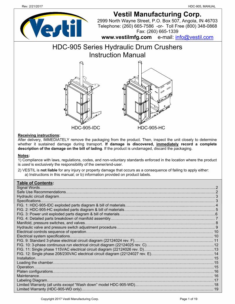
HDC-905 Series Hydraulic Drum Crushers Instruction Manual
HDC-905-IDC HDC-905-HC
Receiving instructions: After delivery, IMMEDIATELY remove the packaging from the product. Then, inspect the unit closely to determine whether it sustained damage during transport. If damage is discovered, immediately record a complete description of the damage on the bill of lading. If the product is undamaged, discard the packaging.
Notes: 1) Compliance with laws, regulations, codes, and non-voluntary standards enforced in the location where the product is used is exclusively the responsibility of the owner/end-user.
2) VESTIL is not liable for any injury or property damage that occurs as a consequence of failing to apply either: a) Instructions in this manual; or b) information provided on product labels.
Vestil Manufacturing Corp. 2999 North Wayne Street, P.O. Box 507, Angola, IN 46703 Telephone: (260) 665-7586 -or- Toll Free (800) 348-0868
Fax: (260) 665-1339 www.vestilmfg.com e-mail: [email protected]
Table of Contents: Signal Words……………………………………………..……………………………………………………………..………….. 2 Safe Use Recommendations……………..……………………………………………..…………………………..…….……… 2 Hydraulic circuit diagram…….……………………………………………………………………………………………………. 3 Specifications…………………………………..………………………………………………………..…………..…….………. 3 FIG. 1: HDC-905-IDC exploded parts diagram & bill of materials………...……………………………..…………………… 4 FIG. 2: HDC-905-HC exploded parts diagram & bill of materials…………………………………………………………….. 5 FIG. 3: Power unit exploded parts diagram & bill of materials………...…………………..…………………………………..6 FIG. 4: Detailed parts breakdown of manifold assembly……………… ……………………………………………………… 7 Manifold, pressure switches, and valves……………….……………………………………………………………………….. 8 Hydraulic valve and pressure switch adjustment procedure………………………………………………………………….. 9 Electrical controls sequence of operation……………………………………………………………………………………… 10 Electrical system specifications…………………………………………………………………………………………………. 10 FIG. 9: Standard 3-phase electrical circuit diagram (22124024 rev. F)…………………………………………………….. 11 FIG. 10: 3-phase continuous run electrical circuit diagram (22124025 rev. C)…………………………………………….. 12 FIG. 11: Single phase 115VAC electrical circuit diagram (22124026 rev. D)……………………………………………….13 FIG. 12: Single phase 208/230VAC electrical circuit diagram (22124027 rev. E)…………………………………………. 14 Installation…………………………………………………………………………………………………………………………. 15 Loading the chamber……………………………………………………………………………………………………………... 15 Operation………….……………………………………………………………………………………………………………….. 15 Platen configurations…………………………………………………………………………………………………………… ... 16 Maintenance………………………………………………………………………………………………………………………. 16 Labeling Diagram…………….....………………………………………………………………………………………………… 17 Limited Warranty (all units except “Wash down” model HDC-905-WD)...……………..………………………………..….. 18 Limited Warranty (HDC-905-WD only)…………………………………………………………………………………………. 19
Rev. 2/21/2017 HDC-905, MANUAL
Copyright 2017 Vestil Manufacturing Corp. Page 2 of 19
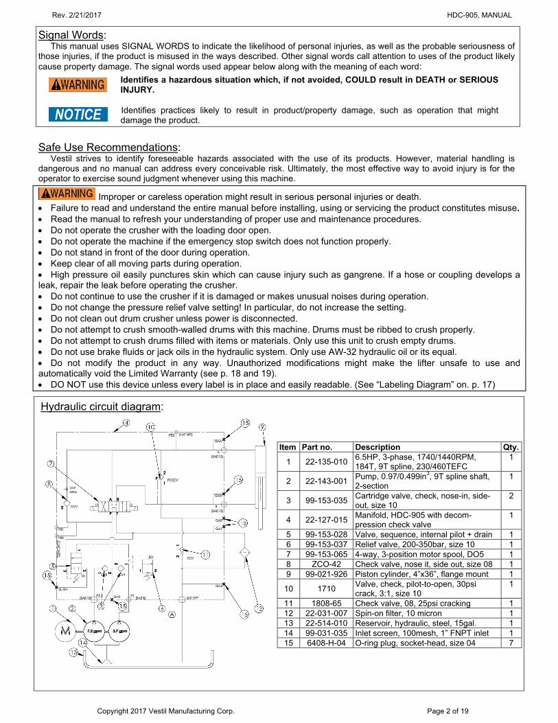
Signal Words: This manual uses SIGNAL WORDS to indicate the likelihood of personal injuries, as well as the probable seriousness of
those injuries, if the product is misused in the ways described. Other signal words call attention to uses of the product likely cause property damage. The signal words used appear below along with the meaning of each word:
Identifies a hazardous situation which, if not avoided, COULD result in DEATH or SERIOUS INJURY.
Identifies practices likely to result in product/property damage, such as operation that might damage the product.
Safe Use Recommendations:
Vestil strives to identify foreseeable hazards associated with the use of its products. However, material handling is dangerous and no manual can address every conceivable risk. Ultimately, the most effective way to avoid injury is for the operator to exercise sound judgment whenever using this machine.
Improper or careless operation might result in serious personal injuries or death. Failure to read and understand the entire manual before installing, using or servicing the product constitutes misuse. Read the manual to refresh your understanding of proper use and maintenance procedures. Do not operate the crusher with the loading door open. Do not operate the machine if the emergency stop switch does not function properly. Do not stand in front of the door during operation. Keep clear of all moving parts during operation. High pressure oil easily punctures skin which can cause injury such as gangrene. If a hose or coupling develops a leak, repair the leak before operating the crusher. Do not continue to use the crusher if it is damaged or makes unusual noises during operation. Do not change the pressure relief valve setting! In particular, do not increase the setting. Do not clean out drum crusher unless power is disconnected. Do not attempt to crush smooth-walled drums with this machine. Drums must be ribbed to crush properly. Do not attempt to crush drums filled with items or materials. Only use this unit to crush empty drums. Do not use brake fluids or jack oils in the hydraulic system. Only use AW-32 hydraulic oil or its equal. Do not modify the product in any way. Unauthorized modifications might make the lifter unsafe to use and automatically void the Limited Warranty (see p. 18 and 19). DO NOT use this device unless every label is in place and easily readable. (See “Labeling Diagram” on. p. 17)
Hydraulic circuit diagram:
Item Part no. Description Qty.
1 22-135-010 6.5HP, 3-phase, 1740/1440RPM, 184T, 9T spline, 230/460TEFC
1
2 22-143-001 Pump, 0.97/0.499in3, 9T spline shaft, 2-section
1
3 99-153-035 Cartridge valve, check, nose-in, side-out, size 10
2
4 22-127-015 Manifold, HDC-905 with decom-pression check valve
1
5 99-153-028 Valve, sequence, internal pilot + drain 1 6 99-153-037 Relief valve, 200-350bar, size 10 1 7 99-153-065 4-way, 3-position motor spool, DO5 1 8 ZCO-42 Check valve, nose it, side out, size 08 1 9 99-021-926 Piston cylinder, 4”x36”, flange mount 1
10 1710 Valve, check, pilot-to-open, 30psi crack, 3:1, size 10
1
11 1808-65 Check valve, 08, 25psi cracking 1 12 22-031-007 Spin-on filter, 10 micron 1 13 22-514-010 Reservoir, hydraulic, steel, 15gal. 1 14 99-031-035 Inlet screen, 100mesh, 1” FNPT inlet 1 15 6408-H-04 O-ring plug, socket-head, size 04 7
Rev. 2/21/2017 HDC-905, MANUAL
Copyright 2017 Vestil Manufacturing Corp. Page 3 of 19
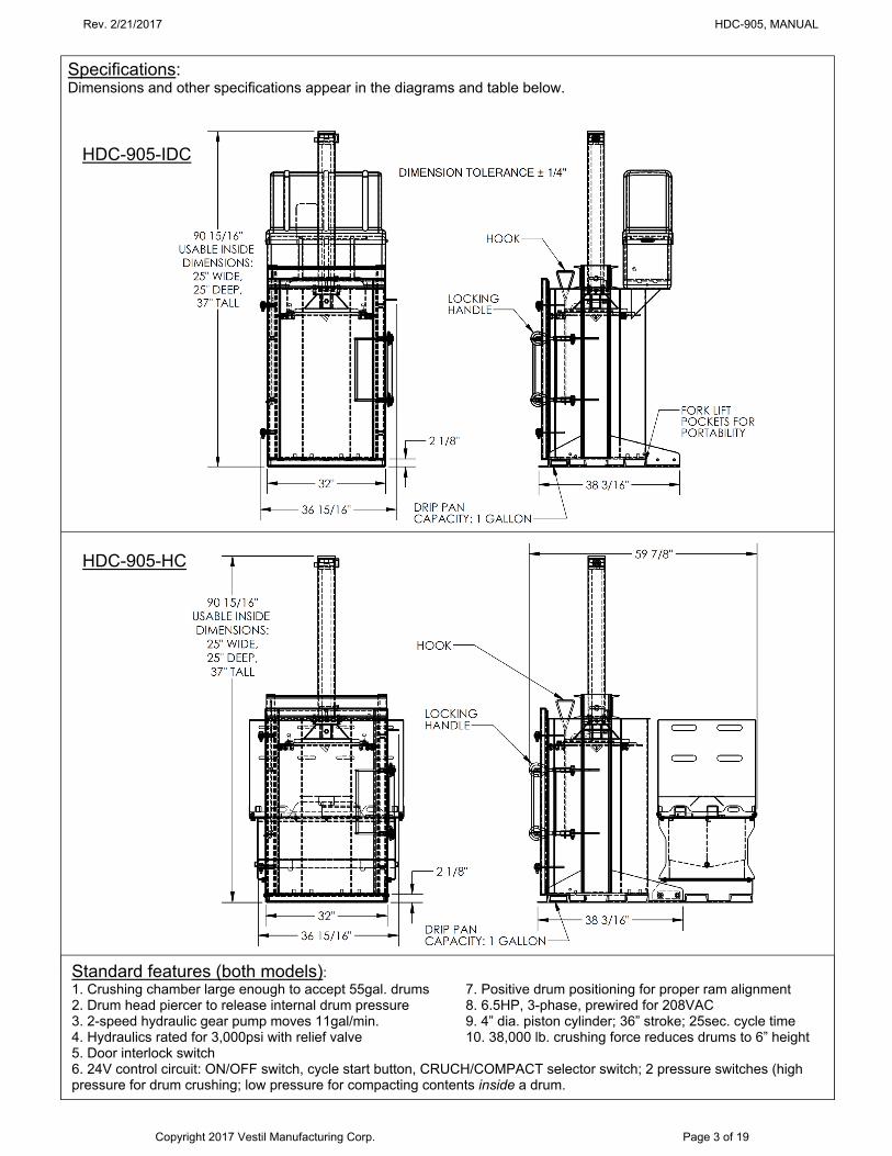
Specifications: Dimensions and other specifications appear in the diagrams and table below.
Standard features (both models): 1. Crushing chamber large enough to accept 55gal. drums 7. Positive drum positioning for proper ram alignment 2. Drum head piercer to release internal drum pressure 8. 6.5HP, 3-phase, prewired for 208VAC 3. 2-speed hydraulic gear pump moves 11gal/min. 9. 4” dia. piston cylinder; 36” stroke; 25sec. cycle time 4. Hydraulics rated for 3,000psi with relief valve 10. 38,000 lb. crushing force reduces drums to 6” height 5. Door interlock switch 6. 24V control circuit: ON/OFF switch, cycle start button, CRUCH/COMPACT selector switch; 2 pressure switches (high pressure for drum crushing; low pressure for compacting contents inside a drum.
HDC-905-IDC
HDC-905-HC
Rev. 2/21/2017 HDC-905, MANUAL
Copyright 2017 Vestil Manufacturing Corp. Page 4 of 19
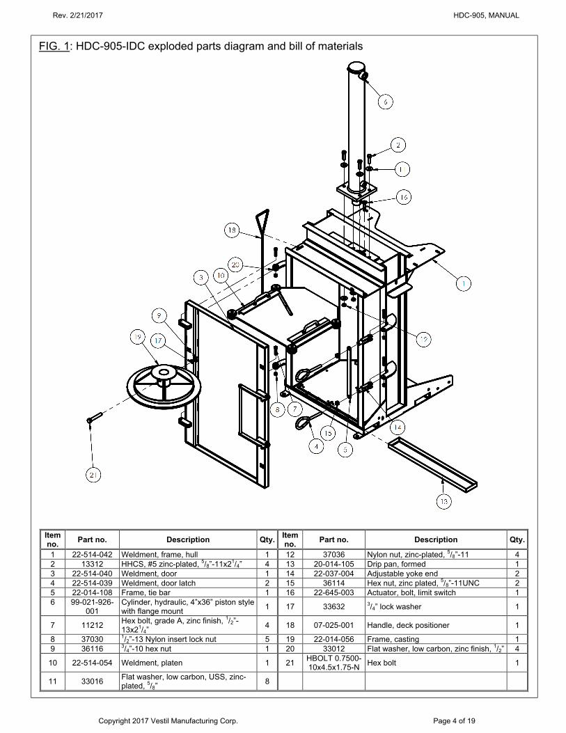
FIG. 1: HDC-905-IDC exploded parts diagram and bill of materials
Item no.
Part no. Description Qty. Item no.
Part no. Description Qty.
1 22-514-042 Weldment, frame, hull 1 12 37036 Nylon nut, zinc-plated, 5/8”-11 4 2 13312 HHCS, #5 zinc-plated, 5/8”-11x21/4” 4 13 20-014-105 Drip pan, formed 1 3 22-514-040 Weldment, door 1 14 22-037-004 Adjustable yoke end 2 4 22-514-039 Weldment, door latch 2 15 36114 Hex nut, zinc plated, 5/8”-11UNC 2 5 22-014-108 Frame, tie bar 1 16 22-645-003 Actuator, bolt, limit switch 1 6 99-021-926-
001 Cylinder, hydraulic, 4”x36” piston style with flange mount
1 17 33632 3/4” lock washer 1
7 11212 Hex bolt, grade A, zinc finish, 1/2”-13x21/4”
4 18 07-025-001 Handle, deck positioner 1
8 37030 1/2”-13 Nylon insert lock nut 5 19 22-014-056 Frame, casting 1 9 36116 3/4”-10 hex nut 1 20 33012 Flat washer, low carbon, zinc finish, 1/2” 4
10 22-514-054 Weldment, platen 1 21 HBOLT 0.7500-10x4.5x1.75-N
Hex bolt 1
11 33016 Flat washer, low carbon, USS, zinc-plated, 5/8”
8
Rev. 2/21/2017 HDC-905, MANUAL
Copyright 2017 Vestil Manufacturing Corp. Page 5 of 19
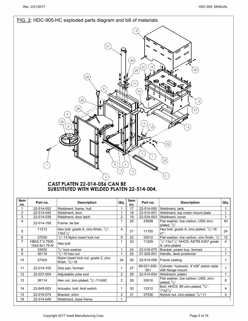
FIG. 2: HDC-905-HC exploded parts diagram and bill of materials
Item no.
Part no. Description Qty. Item no.
Part no. Description Qty.
1 22-514-052 Weldment, frame, hull 1 17 22-514-050 Weldment, tank 1 2 22-514-040 Weldment, door 1 18 22-514-051 Weldment, top motor mount plate 1 3 22-514-039 Weldment, door latch 2 19 22-524-003 Weldment, cover 1 4
22-014-108 Frame, tie bar 1 20 33008 Flat washer, low carbon, USS zinc-
plated, 3/8” 40
5 11212 Hex bolt, grade A, zinc-finish, 1/2”-
13x21/4” 4
21 11105 Hex bolt, grade A, zinc-plated, 3/8”-16 x1”
24
6 37030 1/2”-13 Nylon insert lock nut 9 22 33012 Flat washer, low carbon, zinc finish, 1/2” 12 7 HBOLT 0.7500-
10x4.5x1.75-N Hex bolt
1 23 11209 1/2”-13x11/2” HHCS, ASTM A307 grade A, zinc-plated
4
8 33632 3/4” lock washer 1 24 22-016-075 Bracket, power box, formed 1 9 36116 3/4”-10 hex nut 1 25 07-025-001 Handle, deck positioner 1
10 37024 Nylon insert lock nut, grade 2, zinc finish, 3/8”-16
24 26 22-014-056 Frame casting 1
11 22-014-105 Drip pan, formed 1 27 99-021-926-
001 Cylinder, hydraulic, 4”x36” piston style with flange mount
1
12 22-037-004 Adjustable yoke end 2 28 22-514-054 Weldment, platen 1
13 36114 Hex nut, zinc-plated, 5/8”-11UNC 2 29 33016 Flat washer, low carbon, USS, zinc-plated, 5/8”
8
14 22-645-003 Actuator, bolt, limit switch 1 30 13312 Bolt, HHCS, #5 zinc-plated, 5/8”-11x21/4”
4
15 22-016-074 Bracket, shim 2 31 37036 Nylock nut, zinc-plated, 5/8”-11 4 16 22-514-049 Weldment, base frame 1
Rev. 2/21/2017 HDC-905, MANUAL
Copyright 2017 Vestil Manufacturing Corp. Page 6 of 19
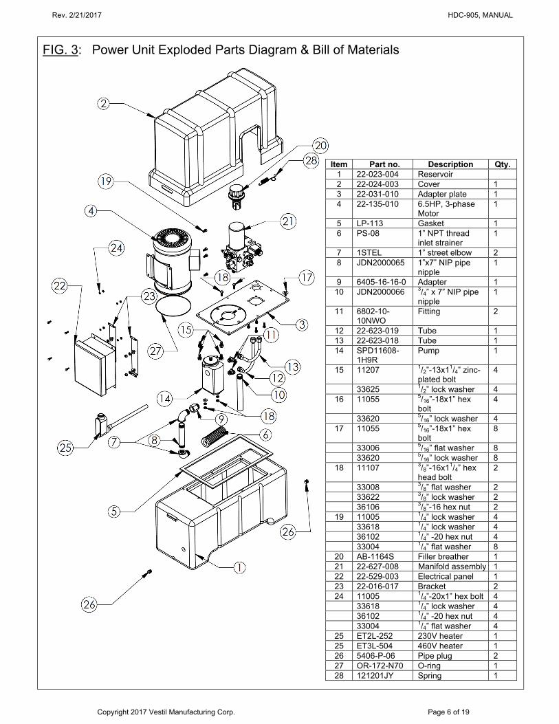
FIG. 3: Power Unit Exploded Parts Diagram & Bill of Materials
Item Part no. Description Qty. 1 22-023-004 Reservoir 2 22-024-003 Cover 1 3 22-031-010 Adapter plate 1 4 22-135-010 6.5HP, 3-phase
Motor 1
5 LP-113 Gasket 1 6 PS-08 1” NPT thread
inlet strainer 1
7 1STEL 1” street elbow 2 8 JDN2000065 1”x7” NIP pipe
nipple 1
9 6405-16-16-0 Adapter 1 10 JDN2000066 3/4” x 7” NIP pipe
nipple 1
11 6802-10-10NWO
Fitting 2
12 22-623-019 Tube 1 13 22-623-018 Tube 1 14 SPD11608-
1H9R Pump 1
15 11207 1/2”-13x11/4” zinc-plated bolt
4
33625 1/2” lock washer 4 16 11055 5/16”-18x1” hex
bolt 4
33620 5/16” lock washer 4 17 11055 5/16”-18x1” hex
bolt 8
33006 5/16” flat washer 8 33620 5/16” lock washer 8
18 11107 3/8”-16x11/4” hex head bolt
2
33008 3/8” flat washer 2 33622 3/8” lock washer 2 36106 3/8”-16 hex nut 2
19 11005 1/4” lock washer 4 33618 1/4” lock washer 4 36102 1/4” -20 hex nut 4 33004 1/4” flat washer 8
20 AB-1164S Filler breather 1 21 22-627-008 Manifold assembly 1 22 22-529-003 Electrical panel 1 23 22-016-017 Bracket 2 24 11005 1/4”-20x1” hex bolt 4 33618 1/4” lock washer 4 36102 1/4” -20 hex nut 4 33004 1/4” flat washer 4
25 ET2L-252 230V heater 1 25 ET3L-504 460V heater 1 26 5406-P-06 Pipe plug 2 27 OR-172-N70 O-ring 1 28 121201JY Spring 1
Rev. 2/21/2017 HDC-905, MANUAL
Copyright 2017 Vestil Manufacturing Corp. Page 7 of 19
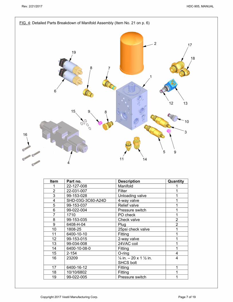
FIG. 4: Detailed Parts Breakdown of Manifold Assembly (Item No. 21 on p. 6)
11
14
5
9
10
3
12
13
17
18
2
7
8
4
16
15
9
1
6
19
8
Item Part no. Description Quantity 1 22-127-008 Manifold 1 2 22-031-007 Filter 1 3 99-153-028 Unloading valve 1 4 SHD-03G-3C60-A24D 4-way valve 1 5 99-153-037 Relief valve 1 6 99-022-004 Pressure switch 1 7 1710 PO check 1 8 99-153-035 Check valve 2 9 6408-H-04 Plug 2
10 1808-25 25psi check valve 1 11 6400-10-10 Fitting 1 12 99-153-015 2-way valve 1 13 99-034-008 24VAC coil 1 14 6400-10-08-0 Fitting 1 15 2-154 O-ring 4 16 23209 ¼ in. – 20 x 1 ½ in.
SHCS bolt 4
17 6400-16-12 Fitting 1 18 10/10/6802 Fitting 1 19 99-022-005 Pressure switch 1
Rev. 2/21/2017 HDC-905, MANUAL
Copyright 2017 Vestil Manufacturing Corp. Page 8 of 19
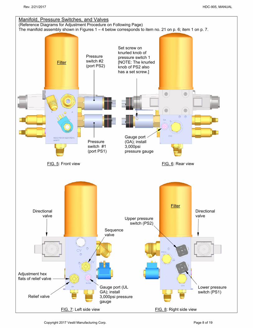
FIG. 5: Front view FIG. 6: Rear view
FIG. 7: Left side view FIG. 8: Right side view
Pressure switch #2 (port PS2)
Pressure switch #1 (port PS1)
Gauge port (GA); install 3,000psi pressure gauge
Gauge port (UL GA); install 3,000psi pressure gauge
Set screw on knurled knob of pressure switch 1 [NOTE: The knurled knob of PS2 also has a set screw.]
Filter
Directional valve
Directional valve
Lower pressure switch (PS1)
Upper pressure switch (PS2)
Filter
Manifold, Pressure Switches, and Valves (Reference Diagrams for Adjustment Procedure on Following Page)
The manifold assembly shown in Figures 1 – 4 below corresponds to item no. 21 on p. 6; item 1 on p. 7.
Adjustment hex flats of relief valve
Sequence valve
Relief valve
Rev. 2/21/2017 HDC-905, MANUAL
Copyright 2017 Vestil Manufacturing Corp. Page 9 of 19
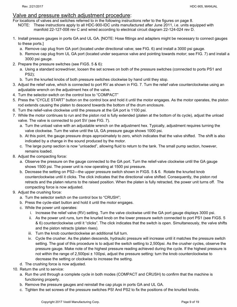
Valve and pressure switch adjustment procedure: For locations of valves and switches referred to in the following instructions refer to the figures on page 8.
NOTE: These instructions apply to all HDC-900-IDC units manufactured after June 2011, i.e. units equipped with manifold 22-127-008 rev C and wired according to electrical circuit diagram 22-124-024 rev D.
1. Install pressure gauges in ports GA and UL GA. [NOTE: Hose fittings and adapters might be necessary to connect gauges
to these ports.] a. Remove cap plug from GA port (located under directional valve; see FIG. 6) and install a 3000 psi gauge. b. Remove cap plug from UL GA port (located under sequence valve and pointing towards motor; see FIG. 7) and install a
3000 psi gauge. 2. Prepare the pressure switches (see FIGS. 5 & 6):
a. Using a standard screwdriver, loosen the set screws on both of the pressure switches (connected to ports PS1 and PS2);
b. Turn the knurled knobs of both pressure switches clockwise by hand until they stop. 3. Adjust the relief valve, which is connected to port RV as shown in FIG. 7. Turn the relief valve counterclockwise using an
adjustable wrench on the adjustment hex of the valve. 4. Turn the selector-switch on the control box to “COMPACT” 5. Press the “CYCLE START” button on the control box and hold it until the motor engages. As the motor operates, the piston
rod extends causing the platen to descend towards the bottom of the drum enclosure. 6. Turn the relief-valve clockwise until the pressure at the GA port is 1100 psi. 7. While the motor continues to run and the piston rod is fully extended (platen at the bottom of its cycle), adjust the unload
valve. The valve is connected to port SV (see FIG. 7). a. Turn the unload valve with an adjustable wrench on the adjustment hex. Typically, adjustment requires turning the
valve clockwise. Turn the valve until the UL GA pressure gauge shows 1000 psi. b. At this point, the gauge pressure drops approximately to zero, which indicates that the valve shifted. The shift is also
indicated by a change in the sound produced by the motor. c. The large pump section is now “unloaded”, allowing fluid to return to the tank. The small pump section, however,
remains loaded. 8. Adjust the compacting force:
a. Observe the pressure on the gauge connected to the GA port. Turn the relief-valve clockwise until the GA gauge shows 1500 psi. The power unit is now operating at 1500 psi pressure.
b. Decrease the setting on PS2—the upper pressure switch shown in FIGS. 5 & 6. Rotate the knurled knob counterclockwise until it clicks. The click indicates that the directional valve shifted. Consequently, the piston rod retracts and the platen returns to the raised position. When the platen is fully retracted, the power unit turns off. The compacting force is now adjusted.
9. Adjust the crushing force: a. Turn the selector switch on the control box to “CRUSH”; b. Press the cycle-start button and hold it until the motor engages. c. While the power unit operates:
i. Increase the relief valve (RV) setting. Turn the valve clockwise until the GA port gauge displays 3000 psi. ii. As the power unit runs, turn the knurled knob on the lower pressure switch connected to port PS1 (see FIGS. 5
& 6) counterclockwise until it “clicks”. The click indicates that the switch is open. Simultaneously, the valve shifts and the piston retracts (platen rises).
iii. Turn the knob counterclockwise an additional full turn. iv. Cycle the crusher. As the platen descends, hydraulic pressure will increase until it matches the pressure switch
setting. The goal of this procedure is to adjust the switch setting to 2,500psi. As the crusher cycles, observe the pressure gauge. Make note of the highest pressure reading achieved during the cycle. If the highest pressure is not within the range of 2,500psi ± 100psi, adjust the pressure setting: turn the knob counterclockwise to decrease the setting or clockwise to increase the setting.
d. The crushing force is now adjusted. 10. Return the unit to service:
a. Run the unit through a complete cycle in both modes (COMPACT and CRUSH) to confirm that the machine is functioning properly.
b. Remove the pressure gauges and reinstall the cap plugs in ports GA and UL GA. c. Tighten the set screws of the pressure switches PS! And PS2 to fix the positions of the knurled knobs.
Rev. 2/21/2017 HDC-905, MANUAL
Copyright 2017 Vestil Manufacturing Corp. Page 10 of 19
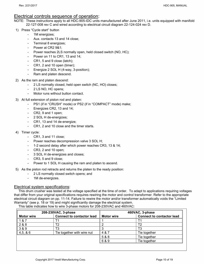
Electrical controls sequence of operation: NOTE: These instructions apply to all HDC-905-IDC units manufactured after June 2011, i.e. units equipped with manifold
22-127-008 rev C and wired according to electrical circuit diagram 22-124-024 rev D.
1) Press “Cycle start” button - 1M energizes; - Aux. contacts 13 and 14 close; - Terminal 8 energizes; - Power at CR2 9&1; - Power reaches 2LS normally open, held closed switch (NO, HC); - Power on 11 to CR1, 13 and 14; - CR1, 5 and 9 close (latch); - CR1, 2 and 10 open (timer); - Energize 2 SOL H (4-way, 3-position); - Ram and platen descend.
2) As the ram and platen descend: - 2 LS normally closed, held open switch (NC, HO) closes; - 2 LS NO, HC opens; - Motor runs without button contact.
3) At full extension of piston rod and platen: - PS1 (if in “CRUSH” mode) or PS2 (if in “COMPACT” mode) make; - Energizes CR2, 13 and 14; - CR2, 9 and 1 open; - 2 SOL H de-energizes; - CR1, 13 and 14 de-energize; - CR1, 2 and 10 close and the timer starts.
4) Timer cycle: - CR1, 3 and 11 close; - Power reaches decompression valve 3 SOL H; - 1-2 second delay after which power reaches CR3, 13 & 14; - CR3, 2 and 10 open; - 3 SOL H de-energizes and closes; - CR3, 5 and 9 close; - Power to 1 SOL H causing the ram and platen to ascend.
5) As the piston rod retracts and returns the platen to the ready position: - 2 LS normally closed switch opens; and - 1M de-energizes.
Electrical system specifications:
This drum crusher was tested at the voltage specified at the time of order. To adapt to applications requiring voltages that differ from your original specifications requires rewiring the motor and control transformer. Refer to the appropriate electrical circuit diagram on pp. 11-14. Failure to rewire the motor and/or transformer automatically voids the “Limited Warranty” (see p. 18 or 19) and might significantly damage the electrical system.
This table indicates how to wire 3-phase motors for 208-230VAC and 460VAC:
208-230VAC, 3-phase 460VAC, 3-phase Motor wire Connect to contactor lead Motor wire Connect to contactor lead 1 & 7 T1 1 T1 2 & 8 T2 2 T2 3 & 9 T3 3 T3 4,5, & 6 Tie together with wire nut 4 & 7 Tie together 5 & 8 Tie together 6 & 9 Tie together
Rev. 2/21/2017 HDC-905, MANUAL
Copyright 2017 Vestil Manufacturing Corp. Page 11 of 19
FIG. 9: Standard 3-phase electrical circuit diagram
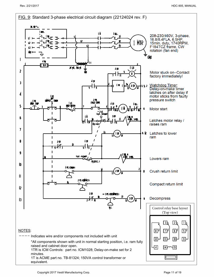
FIG. 9: Standard 3-phase electrical circuit diagram (22124024 rev. F)
NOTES:
Indicates wire and/or components not included with unit
*All components shown with unit in normal starting position, i.e. ram fully raised and cabinet door open.
1TR is ICM Controls: part no. ICM1028; Delay-on-make set for 2 minutes.
1T is ACME part no. TB-81324; 150VA control transformer or equivalent.
Rev. 2/21/2017 HDC-905, MANUAL
Copyright 2017 Vestil Manufacturing Corp. Page 12 of 19
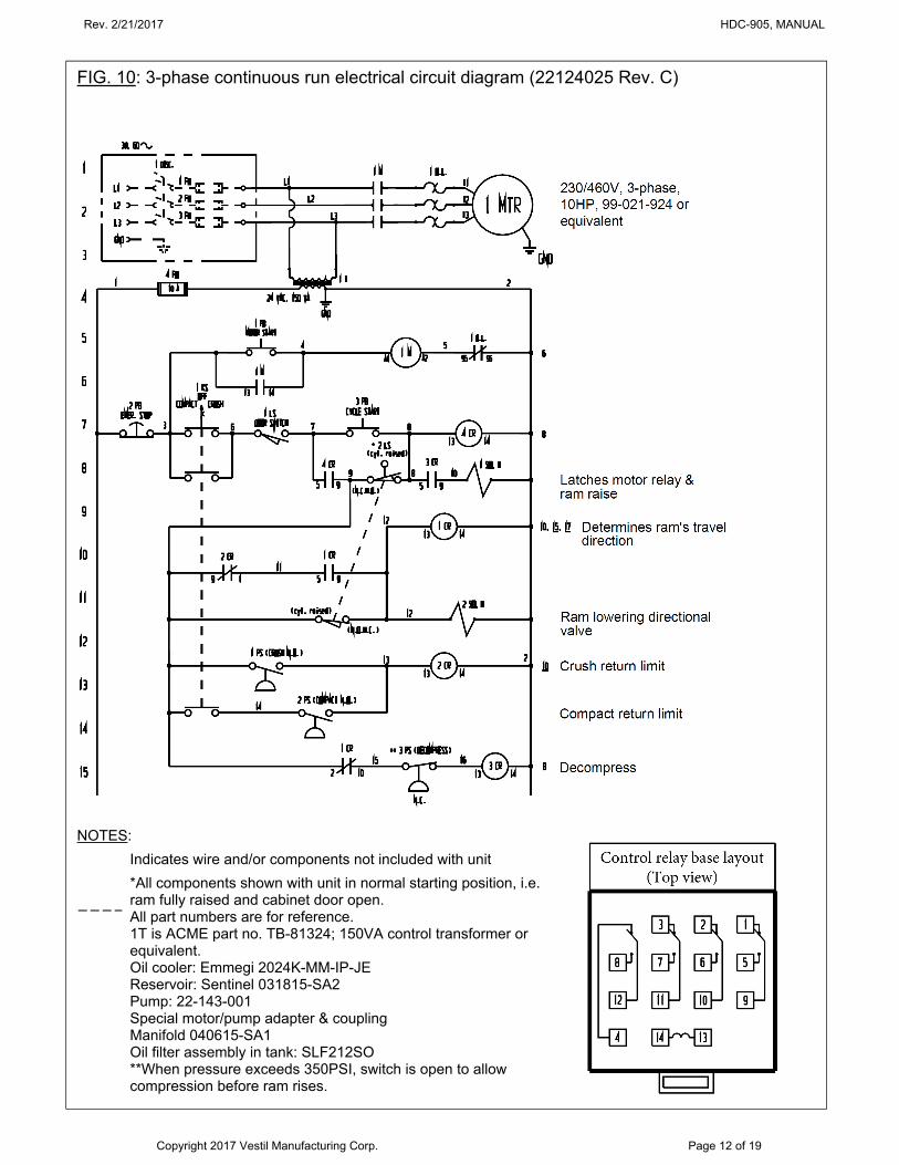
FIG. 10: 3-phase continuous run electrical circuit diagram (22124025 Rev. C)
NOTES:
Indicates wire and/or components not included with unit
*All components shown with unit in normal starting position, i.e. ram fully raised and cabinet door open.
All part numbers are for reference. 1T is ACME part no. TB-81324; 150VA control transformer or
equivalent. Oil cooler: Emmegi 2024K-MM-IP-JE Reservoir: Sentinel 031815-SA2 Pump: 22-143-001 Special motor/pump adapter & coupling Manifold 040615-SA1 Oil filter assembly in tank: SLF212SO **When pressure exceeds 350PSI, switch is open to allow
compression before ram rises.
Rev. 2/21/2017 HDC-905, MANUAL
Copyright 2017 Vestil Manufacturing Corp. Page 13 of 19
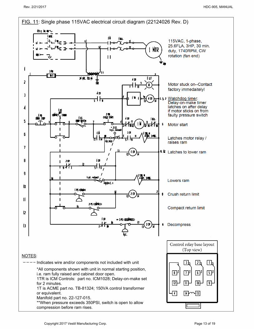
FIG. 11: Single phase 115VAC electrical circuit diagram (22124026 Rev. D)
NOTES:
Indicates wire and/or components not included with unit
*All components shown with unit in normal starting position, i.e. ram fully raised and cabinet door open.
1TR is ICM Controls: part no. ICM1028; Delay-on-make set for 2 minutes.
1T is ACME part no. TB-81324; 150VA control transformer or equivalent.
Manifold part no. 22-127-015. **When pressure exceeds 350PSI, switch is open to allow
compression before ram rises.
Rev. 2/21/2017 HDC-905, MANUAL
Copyright 2017 Vestil Manufacturing Corp. Page 14 of 19
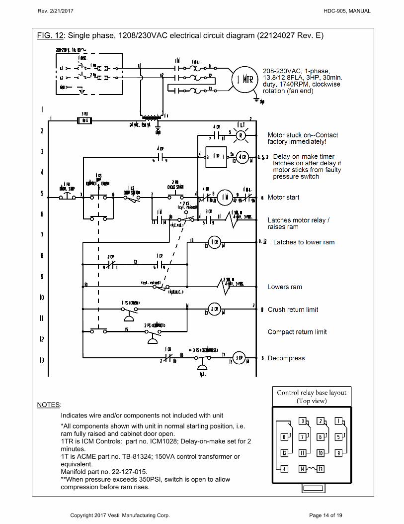
FIG. 12: Single phase, 1208/230VAC electrical circuit diagram (22124027 Rev. E)
NOTES:
Indicates wire and/or components not included with unit
*All components shown with unit in normal starting position, i.e. ram fully raised and cabinet door open.
1TR is ICM Controls: part no. ICM1028; Delay-on-make set for 2 minutes.
1T is ACME part no. TB-81324; 150VA control transformer or equivalent.
Manifold part no. 22-127-015. **When pressure exceeds 350PSI, switch is open to allow
compression before ram rises.
Rev. 2/21/2017 HDC-905, MANUAL
Copyright 2017 Vestil Manufacturing Corp. Page 15 of 19
Installation: The following items are necessary to install the device: Fork truck. Lag bolts, masonry drill, masonry bit, and wrench for lag bolt, grout, and steel shims. Power circuit with voltage matching the voltage of the unit including fuses and disconnect or circuit breakers.
Minimize voltage drop by using adequate wire size. Refer to NEC 70 for power circuit specifications. Move the crusher to its installation location. If using a fork truck, insert the forks into the fork tubes. Drive as far
forward as possible while being careful not to damage the door hinges or door closure mechanism. Once the unit is placed in its installation location, anchor it to the floor with anchor bolts selected by your building engineer. To complete the installation:
1. Connect the power source as shown in the appropriate electrical circuit diagram on pp. 11-14. 2. Cycle the unit a few times; then check the oil level in the reservoir. Add oil, if necessary. NOTE: Only use
ISO AW-32 hydraulic fluid or its equivalent.
Loading the chamber: In crushing mode, this device will crush standard 55 gallon (or smaller) ribbed steel drums. It should not be used to
crush smooth-walled drums (without ribs), which are more resistant to crushing and require much higher crushing forces. [NOTE: The machine might not crush a particular ribbed steel drum. It is also possible that the crusher will sustain minor damage during normal operation.]
In compaction mode, the machine should be used to reduce easily compressible materials loaded inside a drum. [NOTE: Crushing and compacting operations must be performed independently. Do not attempt to crush drums loaded with material. For instance, do not fill drums with scrap metal, paint cans, oil filters, etc. and then attempt to crush the drum and the contents. The crusher might be severely damaged in the process.]
Before operating the machine: 1. Confirm that the platen is properly configured for the task. The 2 platen configurations are described on p.
16. 2. Carefully center the item to be crushed or compacted below the platen. An offset can cause uneven loading
and damage the cylinder rod. 3. Make sure the drum is empty if operating in CRUSH mode.
Operation: To operate the crusher: 1) select the appropriate platen configuration (see "Platen configurations" on p. 16); 2)
place a drum inside the crusher and center it beneath the platen; 3) close the door and latch the door; 4) turn the key switch on the control box to the appropriate mode, i.e. either CRUSH or COMPACT; 5) pull out the red emergency stop button; 6) press the “CYCLE START” button and hold it until the motor engages. NOTE: Each unit is equipped with a momentary contact control. To begin a crushing or compacting cycle, simply press the START button and hold it until the motor engages. The ram will extend and retract without having to hold down the button.
The direction of travel is determined by the starting position of the platen. If the platen is fully raised to the top of the cabinet (cylinder fully retracted), the cylinder will extend when the start button is pressed causing the platen to move downwards. Otherwise, the cylinder will retract and raise the platen to the "Home" position. The power unit will turn off at that point. Pressing the cycle start button again will begin a new cycle. The operator must hold the button for a few seconds to latch the circuit (wait until you hear the motor turn on) and begin the cycle.
When the crusher is in home position and the cycle start button is pressed, the cylinder pushes the platen down onto (or into if operating in COMPACT mode) the drum. In order to achieve a short cycle time, both sections of the pump in the power unit drive oil to the cylinder until the cylinder pressure reaches approximately 1000 PSI. At that time, the higher-displacement section recycles oil to the reservoir while the low-displacement, high-pressure section continues to pump oil to the cylinder. This arrangement creates a typical High-Low circuit.
As the platen crushes a drum, or compacts the contents of a drum, the cylinder pressure increases until it reaches the set-point of a particular pressure switch. The valve shifts to center and a timer activates to control the period of decompression. When the decompression period ends, the directional valve shifts and reverses the direction of oil flow to the cylinder. Reversing the flow of oil causes the cylinder to retract and raise the platen to the home position. When the cylinder returns the platen all the way to the top of the cabinet, the power unit turns off. At this point, the cabinet door can be opened to empty the chamber.
The ram can be stopped at any point during a cycle. To stop the ram, press the red emergency stop button located on the control panel. Pressing the button instantly stops the motor and prevents the cylinder from cycling any further. To disengage the stop button, pull it out. Press the cycle start button again to retract the cylinder and returns the platen to the home position. The crusher is again ready for normal operation.
Rev. 2/21/2017 HDC-905, MANUAL
Copyright 2017 Vestil Manufacturing Corp. Page 16 of 19
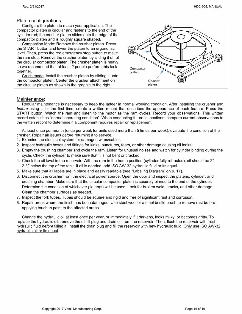
Platen configurations:
Configure the platen to match your application. The compactor platen is circular and fastens to the end of the cylinder rod; the crusher platen slides onto the edge of the compactor platen and is roughly square shaped.
Compaction Mode: Remove the crusher platen. Press the START button and lower the platen to an ergonomic level. Then, press the red emergency stop button to make the ram stop. Remove the crusher platen by sliding it off of the circular compactor platen. The crusher platen is heavy, so we recommend that at least 2 people perform this task together.
Crush mode: Install the crusher platen by sliding it unto the compactor platen. Center the crusher attachment on the circular platen as shown in the graphic to the right.
Maintenance: Regular maintenance is necessary to keep the ladder in normal working condition. After installing the crusher and
before using it for the first time, create a written record that describes the appearance of each feature. Press the START button. Watch the ram and listen to the motor as the ram cycles. Record your observations. This written record establishes “normal operating condition”. When conducting future inspections, compare current observations to the written record to determine if a component requires repair or replacement.
At least once per month (once per week for units used more than 5 times per week), evaluate the condition of the crusher. Repair all issues before returning it to service. 1. Examine the electrical system for damaged wires/cables. 2. Inspect hydraulic hoses and fittings for kinks, punctures, tears, or other damage causing oil leaks. 3. Empty the crushing chamber and cycle the ram. Listen for unusual noises and watch for cylinder binding during the
cycle. Check the cylinder to make sure that it is not bent or cracked. 4. Check the oil level in the reservoir. With the ram in the home position (cylinder fully retracted), oil should be 2” –
21/2” below the top of the tank. If oil is needed, add ISO AW-32 hydraulic fluid or its equal. 5. Make sure that all labels are in place and easily readable (see “Labeling Diagram” on p. 17). 6. Disconnect the crusher from the electrical power source. Open the door and inspect the platens, cylinder, and
crushing chamber. Make sure that the circular compactor platen is securely pinned to the end of the cylinder. Determine the condition of whichever platen(s) will be used. Look for broken weld, cracks, and other damage. Clean the chamber surfaces as needed.
7. Inspect the fork tubes. Tubes should be square and rigid and free of significant rust and corrosion. 8. Repair areas where the finish has been damaged. Use steel wool or a steel bristle brush to remove rust before
applying touchup paint to the affected areas
Change the hydraulic oil at least once per year, or immediately if it darkens, looks milky, or becomes gritty. To replace the hydraulic oil, remove the oil fill plug and drain oil from the reservoir. Then, flush the reservoir with fresh hydraulic fluid before filling it. Install the drain plug and fill the reservoir with new hydraulic fluid. Only use ISO AW-32 hydraulic oil or its equal.
Compactor platen
Crusher platen
Rev. 2/21/2017 HDC-905, MANUAL
Copyright 2017 Vestil Manufacturing Corp. Page 17 of 19
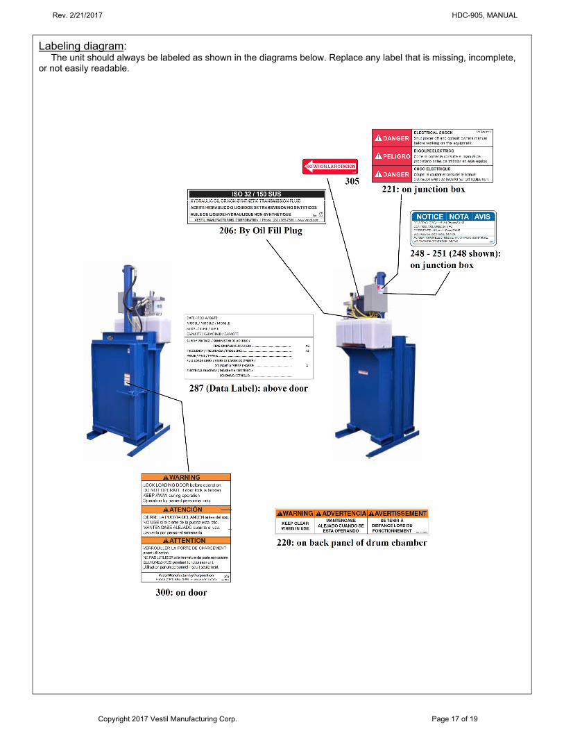
Labeling diagram:
The unit should always be labeled as shown in the diagrams below. Replace any label that is missing, incomplete, or not easily readable.
Rev. 2/21/2017 HDC-905, MANUAL
Copyright 2017 Vestil Manufacturing Corp. Page 18 of 19
LIMITED WARRANTY Vestil Manufacturing Corporation (“Vestil”) warrants HDC-905 series hydraulic drum crushers, excluding “Wash-down” model HDC-905-WD (see limited warranty on following page), to be free of defects in material and workmanship during the warranty period. Our warranty obligation is to provide a replacement for a defective original part if the part is covered by the warranty, after we receive a proper request from the warrantee (you) for warranty service.
Who may request service? Only a warrantee may request service. You are a warrantee if you purchased the product from Vestil or from an authorized distributor AND Vestil has been fully paid.
What is an “original part”? An original part is a part used to make the product as shipped to the warrantee.
What is a “proper request”? A request for warranty service is proper if Vestil receives: 1) a photocopy of the Customer Invoice that displays the shipping date; AND 2) a written request for warranty service including your name and phone number. Send requests by any of the following methods:
Mail Fax Email Vestil Manufacturing Corporation (260) 665-1339 [email protected] 2999 North Wayne Street, PO Box 507 Phone Angola, IN 46703 (260) 665-7586
In the written request, list the parts believed to be defective and include the address where replacements should be delivered.
What is covered under the warranty? After Vestil receives your request for warranty service, an authorized representative will contact you to determine whether your claim is covered by the warranty. Before providing warranty service, Vestil may require you to send the entire product, or just the defective part or parts, to its facility in Angola, IN. The warranty covers defects in the following original dynamic components: motors, hydraulic pumps, electronic controllers, switches and cylinders. It also covers defects in original parts that wear under normal usage conditions (“wearing parts”): bearings, hoses, wheels, seals, brushes, batteries, and the battery charger.
How long is the warranty period? The warranty period for original dynamic components is 1 year. For wearing parts, the warranty period is 90 days. The warranty periods begin on the date when Vestil ships the product to the warrantee. If the product was purchased from an authorized distributor, the periods begin when the distributor ships the product. Vestil may, at its sole discretion, extend the warranty periods for products shipped from authorized distributors by up to 30 days to account for shipping time.
If a defective part is covered by the warranty, what will Vestil do to correct the problem? Vestil will provide an appropriate replacement for any covered part. An authorized representative of Vestil will contact you to discuss your claim.
What is not covered by the warranty? 1. Labor; 2. Freight; 3. Occurrence of any of the following, which automatically voids the warranty:
Product misuse; Negligent operation or repair; Corrosion or use in corrosive environments; Inadequate or improper maintenance; Damage sustained during shipping; Collisions or other incidental contacts causing damage to the product; Unauthorized modifications: DO NOT modify the product IN ANY WAY without first receiving written
authorization from Vestil. Modification(s) might make the product unsafe to use or might cause excessive and/or abnormal wear.
Do any other warranties apply to the product? Vestil Manufacturing Corp. makes no other express warranties. All implied warranties are disclaimed to the extent allowed by law. Any implied warranty not disclaimed is limited in scope to the terms of this Limited Warranty.
Rev. 2/21/2017 HDC-905, MANUAL
Copyright 2017 Vestil Manufacturing Corp. Page 19 of 19
LIMITED WARRANTY Vestil Manufacturing Corporation (“Vestil”) warrants this HDC-905-WD “Wash-down” hydraulic drum crusher to be free of defects in material and workmanship during the warranty period. Our warranty obligation is to provide a replacement for a defective original part if the part is covered by the warranty, after we receive a proper request from the warrantee (you) for warranty service.
Who may request service? Only a warrantee may request service. You are a warrantee if you purchased the product from Vestil or from an authorized distributor AND Vestil has been fully paid.
What is an “original part”? An original part is a part used to make the product as shipped to the warrantee.
What is a “proper request”? A request for warranty service is proper if Vestil receives: 1) a photocopy of the Customer Invoice that displays the shipping date; AND 2) a written request for warranty service including your name and phone number. Send requests by any of the following methods:
Mail Fax Email Vestil Manufacturing Corporation (260) 665-1339 [email protected] 2999 North Wayne Street, PO Box 507 Phone Angola, IN 46703 (260) 665-7586
In the written request, list the parts believed to be defective and include the address where replacements should be delivered.
What is covered under the warranty? After Vestil receives your request for warranty service, an authorized representative will contact you to determine whether your claim is covered by the warranty. Before providing warranty service, Vestil may require you to send the entire product, or just the defective part or parts, to its facility in Angola, IN. The warranty covers defects in the following original dynamic components: motors, hydraulic pumps, electronic controllers, switches and cylinders. It also covers defects in original parts that wear under normal usage conditions (“wearing parts”): bearings, hoses, wheels, seals, brushes, batteries, and the battery charger.
How long is the warranty period? The warranty period for original dynamic components is 30 days. For wearing parts, the warranty period is 30 days. The warranty periods begin on the date when Vestil ships the product to the warrantee. If the product was purchased from an authorized distributor, the periods begin when the distributor ships the product. Vestil may, at its sole discretion, extend the warranty periods for products shipped from authorized distributors by up to 30 days to account for shipping time.
If a defective part is covered by the warranty, what will Vestil do to correct the problem? Vestil will provide an appropriate replacement for any covered part. An authorized representative of Vestil will contact you to discuss your claim.
What is not covered by the warranty? 1. Labor; 2. Freight; 3. Occurrence of any of the following, which automatically voids the warranty:
Product misuse; Negligent operation or repair; Corrosion or use in corrosive environments; Inadequate or improper maintenance; Damage sustained during shipping; Collisions or other incidental contacts causing damage to the product; Unauthorized modifications: DO NOT modify the product IN ANY WAY without first receiving written
authorization from Vestil. Modification(s) might make the product unsafe to use or might cause excessive and/or abnormal wear.
Do any other warranties apply to the product? Vestil Manufacturing Corp. makes no other express warranties. All implied warranties are disclaimed to the extent allowed by law. Any implied warranty not disclaimed is limited in scope to the terms of this Limited Warranty.