Embed Size (px)
Citation preview

Vespa would like to thank you
for choosing one of its products. We have prepared this manual to help you to get the very best from your scooter. Please read it carefully before ridingthe scooter for the first time. It contains information, tips and precautions for using your scooter. It also describes features, details and devices to assureyou that you have made the right choice. We believe that if you follow our suggestions, you will soon get to know your new vehicle and it will serve youwell for a long time to come. This booklet forms an integral part of the scooter; should the scooter be sold, it must be transferred to the new owner.
Vespa GTV 250 i.e.

The instructions given in this manual are intended to provide a clear, simple guide to using your scooter; details are also given of routine maintenanceprocedures and regular checks that should be carried out on the vehicle at an Authorised PIAGGIO Dealer or Service Centre. The booklet alsocontains instructions for simple repairs. Any operations not specifically described in this manual require the use of special tools and/or particular technicalknowledge: to carry out these operations refer to any authorised PIAGGIO Dealer or Service Centre.
2
Personal safety
Failure to completely observe these instructions will result in serious risk of personalinjury.
Safeguarding the environment
Sections marked with this symbol indicate the correct use of the vehicle to prevent dam-aging the environment.
Vehicle intactness
The incomplete or non-observance of these regulations leads to the risk of seriousdamage to the vehicle and sometimes even the invalidity of the guarantee.
The signs that you see on this page are very important. They are used to highlight thoseparts of the booklet that should be read with particular care. As you can see, each signconsists of a different graphic symbol, making it quick and easy to locate the varioustopics.
3

4

INDEX
VEHICLE...................................................................................... 7Dashboard................................................................................ 8Analogue instrument panel....................................................... 8Clock......................................................................................... 9
Setting the total and trip odometers...................................... 9Key switch................................................................................. 9
Locking the steering wheel.................................................... 9Releasing the steering wheel................................................ 10
Switch direction indicators........................................................ 10Horn button............................................................................... 11Light switch............................................................................... 11Start-up button.......................................................................... 11Engine stop button.................................................................... 12The immobilizer system............................................................ 12
Keys...................................................................................... 12Immobilizerdevice enabled indicator led............................... 13Operation............................................................................... 13Programming the immobilizer system................................... 14
Accessing the fuel tank............................................................. 15The saddle................................................................................ 16
Opening the saddle............................................................... 17Identification.............................................................................. 18Rear top box opening................................................................ 19
USE.............................................................................................. 21Checks...................................................................................... 22Refuelling.................................................................................. 22Tyre pressure............................................................................ 24Shock absorbers adjustment.................................................... 25Running in................................................................................. 26Starting up the engine............................................................... 26
Precautions........................................................................... 27Difficult start up......................................................................... 27Stopping the engine.................................................................. 28
Stand......................................................................................... 28Automatic transmission............................................................. 29Safe driving............................................................................... 29Rear rack.................................................................................. 31
MAINTENANCE........................................................................... 33Engine oil level.......................................................................... 34
Engine oil level check............................................................ 34Engine oil top-up................................................................... 34Warning light (insufficient oil pressure)................................. 34Engine oil change.................................................................. 35
Hub oil level.............................................................................. 36Tyres......................................................................................... 38Spark plug dismantlement........................................................ 39Removing the air filter............................................................... 40Cooling fluid level...................................................................... 41Checking the brake oil level...................................................... 43Battery....................................................................................... 44
Use of a new battery............................................................. 45Long periods of inactivity.......................................................... 46Fuses........................................................................................ 47Front light group........................................................................ 50
Headlight adjustment............................................................. 51Front direction indicators........................................................... 52Rear optical unit........................................................................ 53Rear turn indicators................................................................... 53Rear-view mirrors...................................................................... 53Front and rear disc brake.......................................................... 54Puncture.................................................................................... 55Periods of inactivity................................................................... 56Cleaning the vehicle.................................................................. 56
TECHNICAL DATA...................................................................... 61Kit equipment............................................................................ 65
SPARE PARTS AND ACCESSORIES........................................ 67
5

Warnings................................................................................... 68PROGRAMMED MAINTENANCE............................................... 71
Scheduled maintenance table................................................... 72
6

Vespa GTV250 i.e.
Chap. 01Vehicle
7

01_01
Dashboard (01_01)
A = Starter buttonB = Engine block Run-Off switch
C = Throttle control
D = Front brake lever
E = Instrument panel
F = Rear brake control lever
G = Horn button
H = Turn indicator switch
I = Light switch
01_02
Analogue instrument panel (01_02)
A = Fuel gaugeB = Headlight warning lightC = High-beam warning lightD = SpeedometerE = ABS Warning light (wiring)F = Coolant temperature warning lightG = Antitheft device Led (immobilizer)H = Engine control telltale light and injection system failure warning lightI = Turn indicator warning lightL = OdometerM = Low oil pressure warning lightN = Low fuel warning light
8
1 Ve
hicl
e

01_03
Clock (01_03)
Located on the instrument panel, it displays hours and minutes with 1 to 24 hour time.Besides hours and minutes, month and day can also be displayed with the «T» button.In order to adjust the above mentioned functions, operate button «U».
01_04
Setting the total and trip odometers (01_04)
The «TRIP» button displays the total and partial kilometres covered when pressedrepeatedly for less than 1 second. It resets the trip odometer when pushed more than3 seconds. Push the «TRIP» button again to return to total odometer value.
01_05
Key switch (01_05)
LOCK = ignition disabled, extractable key, mechanical antitheft device enabled.
OFF = ignition disabled, extractable key, mechanical antitheft device disabled.
ON = Ready to ignition position, non-extractable key, mechanical antitheft device dis-abled, lights on.
Locking the steering wheel
Turn the handlebar to the left (as far as it will go), turn the key to position «LOCK»and remove the key.
9
1 Vehicle

CAUTION
DO NOT TURN THE KEY TO «LOCK» OR «OFF» WHILE RIDING.
Releasing the steering wheel
Reinsert the key and turn it to «OFF».
CAUTION
DO NOT TURN THE KEY TO «LOCK» OR «OFF» WHILE RIDING.
01_06
Switch direction indicators (01_06)
Lever towards "S" = Left turn indicator is switched on;
Lever towards "D" = Right turn indicator is switched on;
The lever returns automatically to position "0" and the turn indicator "B" remains on;press the lever to turn them off.
10
1 Ve
hicl
e

01_07
Horn button (01_07)
Push the «C» button to sound the horn.
01_08
Light switch (01_08)
0 = Low beam and side light
1 = High beam and side light
01_09
Start-up button (01_09)
Starter button "G"
11
1 Vehicle

01_10
Engine stop button (01_10)
0 = OFF
1 = RUN
01_11
01_12
The immobilizer system
In order to enhance theft protection, the scooter is equipped with a «PIAGGIO IM-MOBILIZER » electronic engine locking device that is activated automatically whenthe starter key is removed. Upon start-up, the «PIAGGIO IMMOBILIZER» systemchecks the starter key, and only if this key is recognised will the immobilizer systemallow the scooter to be started.
Keys (01_11, 01_12, 01_13)
Two types of keys come with the vehicle.
The red-handgrip key "A" is the "MASTER" key.
Only a single copy of this key is supplied, which is necessary to program all your otherkeys and for your dealer to perform some maintenance operations. For this reason itis advised that it be used only in exceptional circumstances.
The blue key «B» (single copy supplied) is used for normal operations such as:
- engine start up
- glove-box opening
Together with the two keys, you will be given a CODE CARD bearing the same codeimprinted onto the two keys.
12
1 Ve
hicl
e

01_13
01_14
WARNING
LOSING THE RED KEY PREVENTS ANY REPAIRS OF THE "PIAGGIO IMMOBIL-IZER" SYSTEM AND THE ENGINE CONTROL UNIT.
WARNING
KEEP THE "CODE CARD" AND THE RED HANDGRIP KEY IN A SAFE PLACE(NOT ON YOUR VEHICLE).
Immobilizerdevice enabled indicator led (01_14)
Activation of the «PIAGGIO IMMOBILIZER» system is signalled by a flashing redwarning light.
To reduce battery discharge, the indicator led turns off automatically after 48 hours ofuninterrupted functioning.
Should the system fail, different LED flashing patterns will be provided by an Author-ised Piaggio-Gilera Service Centre with information on the type of fault detected.
Operation
Every time the starter key is removed in the "OFF" or "LOCK" position, the safetysystem activates the immobilizer system. Turning the key to "ON" disables the enginelock, provided that the safety system recognises the code transmitted by the key. Ifthe code is not recognised, turn the key first to "OFF" and then to "ON"; if the lockcannot be disabled, try with the other key supplied (red-coloured). If the engine cannotbe started, contact an Authorised Piaggio Service Centre, which is provided withthe electronic equipment required to detect and repair the system.
When additional keys are required, please note that data storage (up to 7 keys max.)must be done on all keys, both new ones and existing ones.
13
1 Vehicle

Take your scooter to an Authorised Piaggio Service Centre carrying with you thered-handgrip key and all the blue keys in your possession.
The codes of keys not submitted for the new storage procedure are deleted from thememory. Any lost keys will therefore not be enabled to start the engine.
WARNING
EACH KEY HAS ITS OWN AND UNIQUE CODE, WHICH MUST BE STORED BYTHE SYSTEM CONTROL UNIT.
VIOLENT SHOCKS MAY AFFECT THE ELECTRONIC COMPONENTS OF THEKEY.
IF OWNERSHIP OF THE VEHICLE IS TRANSFERRED, THE RED-HANDGRIP KEY(AS WELL AS THE OTHER KEYS) AND THE "CODE CARD" MUST ALSO BETRANSFERRED TO THE NEW OWNER.
Programming the immobilizer system
Below is described the procedure to follow for programming the PIAGGIO IMMOBIL-IZER system and/or for storing other key codes. The programming procedure shouldbe carried out with the engine stop switch set to «RUN».
Procedure start - red key
Insert the red-handgrip key in the switch key (in "OFF" position) and turn it to "ON".After 1 - 3 seconds, turn the key to "OFF" again and pull it out.
Intermediate step - blu key
Within ten seconds after pulling out the red key, insert the black key and promptly turnit to «ON». After 1-3 seconds, turn the key to "OFF" again and pull it out.
In this way, a maximum of 3 blue keys can be programmed by repeating the aboveprocedure and keeping the indicated times.
14
1 Ve
hicl
e

Final step - red key
After pulling out the last blue key, insert the red key again and turn it to "ON" (thisoperation should be performed within 10 seconds of pulling out the previous key).Leave it in this position for 1 to 3 seconds and return it to the «OFF» position.
Proper programming check
Insert the red key disabling the transponder (i.e., tilt the key cap by 90°) and turn thekey to "ON". Perform the engine start-up operation. Ensure that the engine does notstart. Insert the blue key and repeat the start-up operation. Check that engine starts.
WARNING
SHOULD THE ENGINE START WITH THE RED KEY (WITH TRANSPONDER OFF),OR IN THE EVENT OF WRONG OPERATION DURING PROGRAMMING, REPEATTHE PROCEDURE FROM THE BEGINNING.
01_15
Accessing the fuel tank (01_15, 01_16, 01_17)
With the key set to «OFF» or «ON», or with engine on, it is possible to electrically openthe saddle by pressing the button «C». If the saddle opening system does not work,operate the emergency lever «A». Then, unscrew cap «B» and the fuel tank can bereached.
15
1 Vehicle

01_16
01_17
01_18
The saddle (01_18)
Saddles fitted to this scooter are upholstered in Authentic Leather, and are a stylishaccessory to emphasise an already exclusive product such as your Vespa. As leatheris a natural and vivid material, it tends to get "very opaque" aspect as time goes by,an aspect typical of Authentic Leather. This product may also show characteristic un-dertones and strains.
To care and maintain the features of the saddle through time, follow these tips: Do notexpose it to weather changes, when the scooter is parked protect it with the waterproofcover supplied and stored under the saddle.
Periodically, especially during rainy seasons, apply commercially available water-proofing products (footwear spray). Do not apply shoe polish or wax on the saddle soas not to stain your clothes.
16
1 Ve
hicl
e

01_19
01_20
01_21
In case of forced and prolonged exposure to water, dry the saddle far from any heatsource, do not to use alcohol, solvent-based products and pay special care whenrefuelling.
If the saddle gets stained, wipe the area and if necessary wash it with lukewarm waterand neutral soap.
WARNING
DUE TO THE SPECIAL SADDLE STRUCTURE AND COVER CHARACTERISTICS,USE THE SUPPLIED WATERPROOF PROTECTION, PLACED UNDER THE SAD-DLE, EVERY TIME THE SCOOTER HAS TO BE PARKED IN THE OPEN FOR ALONG TIME.
Opening the saddle (01_19, 01_20, 01_21, 01_22)
With the key set to «OFF» or «ON», or with engine on, it is possible to electrically openthe saddle by pressing button «C». If the electric opening does not work, use theemergency lever "A". When the key is set to "LOCK" the saddle cannot be opened.
WARNING
DUE TO THE SPECIAL SADDLE STRUCTURE AND COVER CHARACTERISTICS,USE THE SUPPLIED WATERPROOF PROTECTION, PLACED UNDER THE SAD-DLE, EVERY TIME THE SCOOTER HAS TO BE PARKED IN THE OPEN FOR ALONG TIME.
17
1 Vehicle

01_22
01_23
01_24
Identification (01_23, 01_24, 01_25)
The identification registration numbers consist of a prefix followed by a number stam-ped on both the chassis «A» and the engine «B». These numbers must always beindicated on spare parts requests. To read the chassis number, lift the saddle andremove the helmet compartment «C». We recommend checking that the chassis reg-istration number stamped on the scooter corresponds with that on the scooter'sdocuments.
CAUTION
BE REMINDED THAT ALTERING IDENTIFICATION REGISTRATION NUMBERSCAN LEAD TO SERIOUS PENAL SANCTIONS (IMPOUNDING OF THE VEHICLE,ETC.).
18
1 Ve
hicl
e

01_25
01_26
01_27
Rear top box opening (01_26, 01_27)
Insert the key into the switch and press down until the glove compartment opens. Ifthe switch is set to "LOCK", turn the key to "OFF" or "ON" before pressing it down.
19
1 Vehicle

20
1 Ve
hicl
e

Vespa GTV250 i.e.
Chap. 02Use
21

Checks
Before using the vehicle, check:
1. There is enough fuel in the fuel tank.
2. The correct fluid level for front and rear brakes.
3. That tyres are properly inflated.
4. The correct functioning of tail lights, headlamp, turn indicators, stop light and licenseplate light.
5. The correct functioning of front and rear brakes.
6. The oil level in the gearcase.
7. The engine oil level.
8. The coolant level.
02_01
Refuelling (02_01, 02_02)
Fuel: lift the saddle and unscrew the cap «B». Recommended fuel: Unleaded petrol(95 octane min.). The fuel reserve level is signalled when the warning light «N» turnson.
WARNING
SWITCH OFF THE ENGINE BEFORE REFUELLING WITH PETROL.
PETROL IS HIGHLY INFLAMMABLE.
DO NOT SMOKE AND KEEP OPEN FLAMES AT A DISTANCE:FIRE HAZARD.
DO NOT INHALE FUEL FUMES.
DO NOT ALLOW PETROL TO COME INTO CONTACT WITH HOT ENGINE ORANY PLASTIC PARTS.
22
2 U
se

02_02
CAUTION
PETROL DAMAGES THE PLASTIC PARTS OF THE BODYWORK.
CAUTION
USING OILS OTHER THAN THOSE RECOMMENDED CAN SHORTEN THE LIFEOF THE ENGINE.
CAUTION
DO NOT USE THE VEHICLE TO THE COMPLETE EXHAUSTION OF THE FUEL;IN THE EVENT THAT THIS SHOULD OCCUR, DO NOT ATTEMPT TO START THEENGINE. TURN THE KEY SWITCH TO OFF AND TOP-UP THE TANK AS SOONAS POSSIBLE. FAILURE TO FOLLOW THESE GUIDELINES COULD DAMAGETHE FUEL PUMP AND/OR THE CATALYTIC CONVERTER.
CharacteristicFuel tank capacity
~ 9.2 litres
23
2 Use
02_03
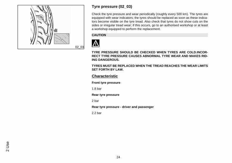
Tyre pressure (02_03)
Check the tyre pressure and wear periodically (roughly every 500 km). The tyres areequipped with wear indicators; the tyres should be replaced as soon as these indica-tors become visible on the tyre tread. Also check that tyres do not show cuts on thesides or irregular tread wear; if this occurs, go to an authorised workshop or at leasta workshop equipped to perform the replacement.
CAUTION
TYRE PRESSURE SHOULD BE CHECKED WHEN TYRES ARE COLD.INCOR-RECT TYRE PRESSURE CAUSES ABNORMAL TYRE WEAR AND MAKES RID-ING DANGEROUS.
TYRES MUST BE REPLACED WHEN THE TREAD REACHES THE WEAR LIMITSSET FORTH BY LAW.
CharacteristicFront tyre pressure
1.8 bar
Rear tyre pressure
2 bar
Rear tyre pressure - driver and passenger
2.2 bar
24
2 U
se

02_04
Shock absorbers adjustment (02_04)
The preloading of the springs can be adjusted to 4 positions using the ring nut locatedin the lower part of the shock absorbers and the specific spanner supplied.
Position 1: Minimum preload: driver only
Position 2 medium preloading: driver only
Position 3 medium preloading: rider and passenger
Position 4: Maximum preload: driver, passenger, and luggage.
In order to carry out this operation you will need to use the specific spanner in the kit.
CAUTION
RIDING THE VEHICLE WITH THE SPRING PRELOADING NOT CORRECTLY SETFOR THE RIDER AND POSSIBLE PASSENGER, COULD REDUCE THE COM-FORT OF THE RIDE AND THE PRECISION OF THE STEERING.
WARNING
WE RECOMMEND WEARING GLOVES WHILE CARRYING OUT THIS OPERA-TION IN ORDER TO AVOID INJURIES.
WARNING
WE STRONGLY RECOMMEND NOT TO ADJUST BOTH SHOCK ABSORBERSWITH DIFFERENT PRELOADING
25
2 Use
02_05
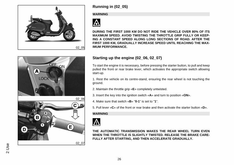
Running in (02_05)
WARNING
DURING THE FIRST 1000 KM DO NOT RIDE THE VEHICLE OVER 80% OF ITSMAXIMUM SPEED. AVOID TWISTING THE THROTTLE GRIP FULLY OR KEEP-ING A CONSTANT SPEED ALONG LONG SECTIONS OF ROAD. AFTER THEFIRST 1000 KM, GRADUALLY INCREASE SPEED UNTIL REACHING THE MAX-IMUM PERFORMANCE.
02_06
02_07
Starting up the engine (02_06, 02_07)
To start the engine it is necessary, before pressing the starter button, to pull and keeppulled the front or rear brake lever, which activates the appropriate switch allowingstart-up.
1. Rest the vehicle on its centre-stand, ensuring the rear wheel is not touching theground.
2. Maintain the throttle grip «E» completely untwisted.
3. Insert the key into the ignition switch «A» and turn to position «ON».
4. Make sure that switch «B» "0-1" is set to "1".
5. Pull lever «C» of the front or rear brake and then activate the starter button «D».
WARNING
THE AUTOMATIC TRANSMISSION MAKES THE REAR WHEEL TURN EVENWHEN THE THROTTLE IS SLIGHTLY TWISTED. RELEASE THE BRAKE CARE-FULLY AFTER STARTING, AND THEN ACCELERATE GRADUALLY.
26
2 U
se
CAUTION
DO NOT START-UP THE ENGINE IN CLOSED AREAS BECAUSE EXHAUSTGASES ARE TOXIC.
Precautions
CAUTION
NEVER STRESS THE ENGINE AT LOW TEMPERATURES IN ORDER TO AVOIDPOSSIBLE DAMAGE. BE CAREFUL NEVER TO EXCEED THE MAXIMUM SPEEDWHILE RUNNING DOWNHILL, IN ORDER TO AVOID DAMAGING THE ENGINE.IN ANY CASE, IN ORDER TO PRESERVE THE ENGINE FROM PROLONGED EX-CESSIVE REVOLUTIONS, THE REVOLUTION LIMITER WILL BE ACTIVATED IFTHE ENGINE SPEED EXCEEDS THE ESTABLISHED THRESHOLD.
WARNING
AFTER A LONG DISTANCE COVERED AT THE MAXIMUM SPEED, DO NOT STOPTHE ENGINE IMMEDIATELY, BUT LET IT RUN AT IDLE FOR A FEW SECONDS.
Difficult start up
In the rare case of flooding the engine, to facilitate start-up, it is possible to try to putthe vehicle into action with the gas hand grip partially or completely open. It is howevernecessary, once the engine is started, to take your vehicle to an Authorised ServiceCentre to determine the cause of this problem and to re-establish the vehicle properfunctioning.
27
2 Use

02_08
02_09
Stopping the engine (02_08, 02_09)
Fully untwist the throttle grip and then turn the switch key «A» to «OFF» (extractablekey), or turn the switch «B» to «0».
CAUTION
DUE TO THE HIGH TEMPERATURES THE CATALYTIC CONVERTER CANREACH, ALWAYS TAKE CARE, WHEN PARKING THE SCOOTER, THAT THEEXHAUST DOES NOT COME INTO CONTACT WITH FLAMMABLE MATERIALS,TO AVOID SERIOUS BURNS.
CAUTION
DO NOT SWITCH OFF THE ENGINE WHILE THE VEHICLE IS MOVING. UN-BURNED FUEL COULD ENTER THE CATALYTIC CONVERTER AND BURN,CAUSING IT TO OVERHEAT AND POSSIBLY DESTROYING IT.
02_10
Stand (02_10)
CENTRE STAND
With your foot push the projection of the centre stand «F » while lifting the vehiclebackwards, holding onto the side handles.
SIDE STAND
Push the projection of the stand "L " with your foot in order to open it and at the sametime lean the vehicle on you.
28
2 U
se

02_11
Automatic transmission (02_11)
To ensure simple, pleasurable riding, the vehicle is equipped with automatic trans-mission with regulator and centrifugal clutch. The system is designed to provide thebest performance (acceleration and consumption) while riding on both flat roads anduphill.
If you have to stop on an uphill slope (traffic lights, traffic jam, etc.) use only the braketo keep the vehicle still, leaving the engine running at idle speed. Using theengine to keep the vehicle still can cause the clutch to overheat, due to thefriction of the clutch mechanism itself against the clutch bell.
It is therefore recommended to avoid conditions of prolonged clutch slippage (otherthan those previously indicated) like driving uphill fully laden on steep slopes or startingoff with driver and passenger at slopes with steepness greater than 25%.
Observe the following precautions if the clutch overheats:
1. Do not continue riding in such conditions.
2. Let the clutch cool down with the engine at idle speed for a few minutes.
02_12
Safe driving (02_12)
WARNING
SOME SIMPLE TIPS ARE PROVIDED BELOW THAT WILL ENABLE YOU TO USEYOUR SCOOTER ON A DAILY BASIS IN GREATER SAFETY AND WITH MOREPEACE OF MIND.<
Your ability and your knowledge of the vehicle form the basis of safe riding. We rec-ommend trying out the vehicle in traffic-free zones to get to know your vehiclecompletely.ALWAYS DRIVE WITHIN YOUR LIMITS
29
2 Use

1. Before riding off, remember to put on your helmet and fasten it correctly.
2. Reduce speed and ride cautiously on uneven roads.
3. Remember that after riding on a long stretch of wet road without using the brakes,the braking effect is initially lower. Given these conditions, it is a good idea to operatethe brakes from time to time.
4. Do not brake hard on a wet surface, on dirt tracks or on any slippery road surface.
5. If you have to brake, use both brakes in order to divide the braking action betweenboth wheels.
6. Avoid starting off by mounting the scooter while it is still resting on its stand. In anycase, the rear wheel should not be turning when in comes into contact with the ground,in order to avoid abrupt departures.
7. If the vehicle is used on roads covered with sand, mud, snow mixed with salt, etc.,clean the brake disc frequently with mild detergent in order to prevent abrasive sub-stances from building up within the holes, which can result in early wear of the brakepads.
8. Any elaboration that modifies the vehicle's performances, such as tampering withoriginal structural parts is strictly forbidden by law, and renders the vehicle not con-forming to the approved type and therefor dangerous to ride.
CAUTION
DO NOT FORGET THAT DRIVING IN A STATE OF DRUNKENNESS, OR WHENUNDER THE EFFECT OF DRUGS OR CERTAIN MEDICINES, CAN BE EXTREME-LY DANGEROUS FOR ONESELF AND FOR OTHERS.
CAUTION
ANY CHANGES TO THE VEHICLE PERFORMANCE AS WELL AS ALTERATIONSTO ORIGINAL STRUCTURAL PARTS IS STRICTLY FORBIDDEN BY LAW, AND
30
2 U
se

RENDERS THE VEHICLE NO LONGER CONFORMING TO THE APPROVED TYPEAND DANGEROUS FOR RIDING.
02_13
Rear rack (02_13)
When riding without packages on the luggage racks, set the corresponding retainerlatch "A" as shown in the photograph.
WARNING
Maximum admissible load: 6 kg
31
2 Use

32
2 U
se

Vespa GTV250 i.e.
Chap. 03Maintenance
33

03_01
03_02
03_03
Engine oil level
In 4T engines, engine oil is used to lubricate the distribution elements, main bearingsand thermal group. An insufficient quantity of oil can cause serious damage tothe engine itself. In all four-stroke engines, a loss of efficiency in oil performance andconsumption should be considered normal. Consumption can particularly reflect theconditions of use (i.e. when driving at "full acceleration" all the time, oil consumptionincreases). The replacement frequencies provided for by the maintenance programmeare defined, depending on the total contents of oil in the engine and average con-sumption measured following standardised methods. In order to prevent any prob-lems, we recommend checking oil level more frequently than indicated in theScheduled Maintenance table or before setting off on long journeys. The vehicleis, however, equipped with an oil pressure warning light on the instrument pan-el.
Engine oil level check (03_01)
Every time the scooter is used, a visual check should be made on the level of theengine oil when the engine is cold. The oil level should be somewhere between theMAX and MIN index marks on the level bar; the check must be made with the scooterupright, resting on the centre stand. If the check is carried out after the vehicle hasbeen used, and therefore with a hot engine, the level line will be lower; in order to carryout a correct check it is necessary to wait at least 10 minutes after the engine hasbeen stopped, so as to get the correct level.
Engine oil top-up
Any topping up with oil must be carried out after the oil level check by adding oil, butnever exceeding the MAX level. The topping up of the level between MIN andMAX requires approx. 200 cc of oil. Every 5000 km, however, the engine oil levelshould be checked and topped up, if necessary, at an Authorised Piaggio ServiceCentre.
Warning light (insufficient oil pressure)
The vehicle is equipped with a warning light that lights up when the key is turned tothe «ON». However, this light should switch off once the engine has been started. Ifthe light comes on while braking, at idle speed or while turning a corner, it isnecessary to check the oil level and top it up if required. If after having topped-
34
3 M
aint
enan
ce

up the oil, the warning light still comes on while braking, at idle speed or whileturning a corner, it will be necessary to take your vehicle to an Authorised Serv-ice Centre.
Engine oil change (03_02, 03_03)
The oil and cartridge filter "C" must be changed after 1,000 km and every 10,000 kmat an authorised Piaggio service centre. The engine should be emptied by drainingthe oil from the drainage cap "B" of the gauze filter on the flywheel side. In order tofacilitate the oil drainage, loosen the cap/dipstick. Since a certain quantity of oil re-mains in the circuit still, the top-up should be carried out with around 600 ÷ 650 cc ofoil from cap "A". Then start up the scooter, leave it running for a few minutes andswitch it off: after five minutes, check the level and if necessary top up without ex-ceeding the MAX. level. The cartridge filter must be replaced at every oil change.For top up and change, use new oil of the recommended type.
WARNING
RUNNING THE ENGINE WITH INSUFFICIENT LUBRICATION OR WITH INADE-QUATE LUBRICANTS ACCELERATES THE WEAR AND TEAR OF THE MOVINGPARTS AND CAN CAUSE IRRETRIEVABLE DAMAGE.
WARNING
EXCESSIVE OIL LEVEL AT TOP-UPS CAN LEAD TO SCALE FORMATION ANDVEHICLE MALFUNCTIONING.
CAUTION
USED OILS CONTAIN SUBSTANCES HARMFUL TO THE ENVIRONMENT. FOROIL REPLACEMENT, CONTACT AN AUTHORISED PIAGGIO SERVICE CENTRE,
35
3 Maintenance

AS THEY ARE EQUIPPED TO DISPOSE OF SPENT OILS IN AN ENVIRONMEN-TALLY FRIENDLY AND LEGAL WAY.
CAUTION
USING OILS OTHER THAN THOSE RECOMMENDED CAN SHORTEN THE LIFEOF THE ENGINE.
Recommended productsAGIP CITY HI TEC 4T
Engine oilSAE 5W-40, API SL, ACEA A3, JASO MA Synthetic oil
03_04
03_05
Hub oil level (03_04, 03_05)
Check the oil in the rear hub. To check the rear hub oil level, proceed as follows:
1) Park the scooter on level ground and rest it on its stand.
2) Unscrew dipstick "A", wipe it clean with a cloth, reinsert it and tighten completely.
3) Pull out the dipstick and check that the oil level is above the first notch from thebottom.
4) Reinsert the dipstick and ensure that it is tightened correctly.
N.B.
The notches on the hub oil level dipstick, except for the one indicating the"MAX" level, refer to other models by the manufacturer and have no specificfunction for this model.
36
3 M
aint
enan
ce

CAUTION
RIDING THE VEHICLE WITH INSUFFICIENT HUB LUBRICATION OR WITH CON-TAMINATED OR IMPROPER LUBRICANTS ACCELERATES THE WEAR ANDTEAR OF THE MOVING PARTS AND CAN CAUSE SERIOUS DAMAGE.
CAUTION
USED OIL CAN HARM THE ENVIRONMENT. COLLECTION AND DISPOSALSHOULD BE CARRIED OUT IN COMPLIANCE WITH CURRENT REGULATIONS.
CAUTION
AN EXCESSIVE QUANTITY OF OIL CAN LEAD TO LEAKAGE, WHICH MAYCAUSE THE ENGINE AND THE WHEEL TO GET DIRTY.
CAUTION
WHEN REPLACING THE HUB OIL DO NOT LET THE OIL COME INTO CONTACTWITH THE REAR BRAKE DISC.
CAUTION
FOR OIL REPLACEMENT, CONTACT ANY AUTHORISED SERVICE CENTRE ASTHEY ARE EQUIPPED TO DISPOSE OF USED OILS IN AN ENVIRONMENTALLYFRIENDLY AND LEGAL WAY.
37
3 Maintenance

Recommended productsAGIP ROTRA 80W-90
Rear hub oilSAE 80W/90 Oil that exceeds the requirements of API GL3 specifications
CharacteristicRear hub oil
250 cc
03_06
Tyres (03_06)
Check periodically (about every 500 km) the tyre pressure. The tyres are equippedwith wear indicators; the tyres should be replaced as soon as these indicators becomevisible on the tyre tread. Also check that the tyres do not show signs of splitting at theside or irregular tread wear; if this occurs, go to an authorised workshop or at least aworkshop equipped to perform the replacement.
CAUTION
TYRE PRESSURE SHOULD BE CHECKED WHEN TYRES ARE COLD.INCOR-RECT TYRE PRESSURE CAUSES ABNORMAL TYRE WEAR AND MAKES RID-ING DANGEROUS.
TYRES MUST BE REPLACED WHEN THE TREAD REACHES THE WEAR LIMITSSET FORTH BY LAW.
TYRESFront tyre Without inner tube 120/70-12" 51P
38
3 M
aint
enan
ce

Rear tyre Without inner tube: 130/70-12" 62P
TYRE PRESSUREFront tyre pressure 1.8 bar
Rear tyre pressure 2 bar
Rear tyre pressure - driver andpassenger
2.2 bar
03_07
03_08
Spark plug dismantlement (03_07, 03_08)
Proceed as follows:
1. lift the saddle «A»
2. lift the helmet compartment «B» and reach into the spark plug with your hand;
3. disconnect cap of the spark plug HV wire;
4. unscrew the spark plug using the spark plug spanners «D» supplied;
5. When refitting, place the spark plug in the hole at the due inclination and screw itby hand until it is finger tight;
6. use the box-spanner«D» supplied only for locking;
7. place cap fully over the spark plug.
WARNING
THE SPARK PLUG MUST BE REMOVED WHEN THE ENGINE IS COLD. THESPARK PLUG MUST BE REPLACED EVERY 20,000 KM. USE OF ELECTRONICCONTROL UNITS OR ELECTRONIC IGNITIONS DIFFERING FROM THOSE REC-OMMENDED CAN SERIOUSLY DAMAGE THE ENGINE.
39
3 Maintenance
CAUTION
THE USE OF SPARK PLUGS OTHER THAN THOSE RECOMMENDED OR ASHIELDLESS SPARK PLUG CAP COULD CAUSE DISTURBANCES TO THE SYS-TEM.
CharacteristicRecommended spark plug
Champion RG 4 PHP
03_09
03_10
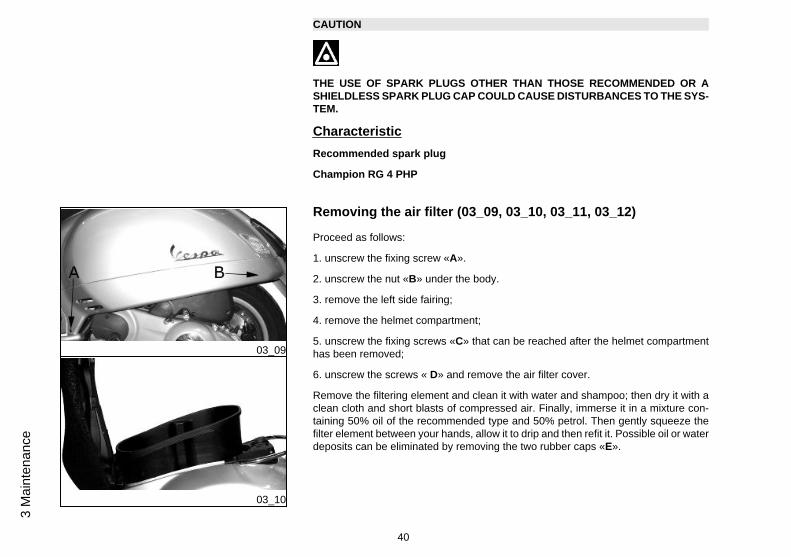
Removing the air filter (03_09, 03_10, 03_11, 03_12)
Proceed as follows:
1. unscrew the fixing screw «A».
2. unscrew the nut «B» under the body.
3. remove the left side fairing;
4. remove the helmet compartment;
5. unscrew the fixing screws «C» that can be reached after the helmet compartmenthas been removed;
6. unscrew the screws « D» and remove the air filter cover.
Remove the filtering element and clean it with water and shampoo; then dry it with aclean cloth and short blasts of compressed air. Finally, immerse it in a mixture con-taining 50% oil of the recommended type and 50% petrol. Then gently squeeze thefilter element between your hands, allow it to drip and then refit it. Possible oil or waterdeposits can be eliminated by removing the two rubber caps «E».
40
3 M
aint
enan
ce

03_11
03_12
CAUTION
IF THE VEHICLE IS USED ON DUSTY ROADS IT IS NECESSARY TO CARRY OUTMAINTENANCE CONTROLS OF THE AIR FILTER TO AVOID DAMAGING THEENGINE.
CAUTION
IN ORDER NOT TO DAMAGE THE VEHICLE PLASTIC COVERS CONTACT ANAUTHORISED SERVICE CENTRE TO HAVE THE AIR FILTER CLEANED.
Recommended productsAGIP FILTER OIL
Oil for air filter spongeMineral oil with specific additives for increased adhesiveness
03_13
Cooling fluid level (03_13, 03_14)
Engine cooling is carried out by a forced-circulation coolant system; the cooling systemholds about 2.100 ÷ 2.150 l of coolant- a mixture of 50% de-ionised water and 50%ethylene-glycol antifreeze solution and corrosion inhibitors. Recommended coolant,supplied with already mixed and ready for use fluid. For proper functioning of the en-gine, the coolant temperature needle should be within the middle zone of the scalebetween the 5th and 8th bar. If the needle points at the 10th bar, the instrument barslit at that moment start flashing. Stop the engine, let it cool down and check the fluidlevel; if the level is OK, take your scooter to an Authorised Piaggio Service Cen-tre. If when using your scooter at a low gear the coolant temperature exceeds theabove values, shut off the engine and let it cool down. Then check the coolant level.if level is OK, take your scooter to an Authorised Piaggio Service Centre. The fluid
41
3 Maintenance

03_14
level must checked every 10,000 kilometres with a cold engine, in the way shownbelow:
a) Place the scooter in a vertical position on the stand.
b) Unscrew the fixing screw «A» and remove the cover.
c) Check the fluid level according to the two marks- MIN and MAX «B» on the reservoir
d) Top up, if necessary, if the fluid level is below the MIN level on the scale inside theexpansion tank. The fluid level must always be between MIN and MAX level
If the fluid is near the minimum level, top-up only when the engine is cold. If it is nec-essary to top up the coolant frequently, or if the expansion tank is completely dry, youshould look for the cause in the cooling system. Have the cooling system checked atan Authorised Piaggio Service Centre. Coolant must be changed every 2 years atan Authorised Piaggio Service Centre.
WARNING
IN ORDER TO AVOID BURNS, DO NOT UNSCREW THE EXPANSION TANK CAPWHILE THE ENGINE IS STILL HOT.
WARNING
IN ORDER TO AVOID HARMFUL FLUID LEAKS WHILE RIDING, IT IS IMPORTANTTO MAKE SURE THAT THE LEVEL NEVER EXCEEDS THE MAXIMUM VALUE.
IN ORDER TO GUARANTEE THE PROPER FUNCTION OF THE ENGINE, IT ISNECESSARY TO KEEP THE RADIATOR GRILLE CLEAN.
Recommended productsSPECIAL AGIP PERMANENT fluid
coolant
42
3 M
aint
enan
ce
Monoethylene glycol-based antifreeze fluid, CUNA NC 956-16
03_15
03_16
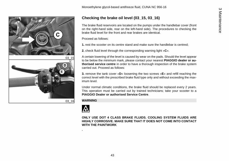
Checking the brake oil level (03_15, 03_16)
The brake fluid reservoirs are located on the pumps under the handlebar cover (fronton the right-hand side, rear on the left-hand side). The procedures to checking thebrake fluid level for the front and rear brakes are identical.
Proceed as follows:
1. rest the scooter on its centre stand and make sure the handlebar is centred;
2. check fluid level through the corresponding warning light «C».
A certain lowering of the level is caused by wear on the pads. Should the level appearto be below the minimum mark, please contact your nearest PIAGGIO dealer or au-thorised service centre in order to have a thorough inspection of the brake systemcarried out. Proceed as follows:
3. remove the tank cover «D» loosening the two screws «E» and refill reaching thecorrect level with the prescribed brake fluid type only and without exceeding the max-imum level.
Under normal climatic conditions, the brake fluid should be replaced every 2 years.This operation must be carried out by trained technicians; take your scooter to aPIAGGIO Dealer or authorised Service Centre.
WARNING
ONLY USE DOT 4 CLASS BRAKE FLUIDS. COOLING SYSTEM FLUIDS AREHIGHLY CORROSIVE. MAKE SURE THAT IT DOES NOT COME INTO CONTACTWITH THE PAINTWORK.
43
3 Maintenance

CAUTION
AVOID CONTACT OF BRAKE FLUID WITH EYES, SKIN, AND CLOTHING. INCASE OF CONTACT, RINSE WITH WATER. THE BRAKING CIRCUIT FLUID ISHYGROSCOPIC, THAT IS, IT ABSORBS HUMIDITY FROM THE SURROUNDINGAIR. IF THE HUMIDITY IN THE BRAKING FLUID EXCEEDS A CERTAIN VALUE,IT WILL LEAD TO INEFFICIENT BRAKING. NEVER USE BRAKING FLUID KEPTIN CONTAINERS THAT HAVE ALREADY BEEN OPENED, OR PARTIALLY USED.
Recommended productsAGIP BRAKE 4
Brake fluidFMVSS DOT 4 Synthetic fluid
03_17
Battery (03_17, 03_18, 03_19)
To reach the battery D, proceed as follows:
1. rest the scooter on its centre stand;
2. unscrew the 4 screws «A», remove the footrest «B».
3. remove the two battery fixing screws «C».
The battery is the electrical device that requires the most frequent inspections anddiligent maintenance. The main points of maintenance to be observed are as follows:
CAUTION
IN ORDER TO AVOID DAMAGING THE ELECTRICAL SYSTEM, NEVER DISCON-NECT THE WIRING WHILE THE ENGINE IS RUNNING. DO NOT TIP THE SCOOT-ER TOO MUCH IN ORDER TO AVOID DANGEROUS LEAKAGE OF BATTERYELECTROLYTE
44
3 M
aint
enan
ce

03_18
03_19
.
CAUTION
ELECTROLYTE CONTAINS SULPHURIC ACID: AVOID CONTACT WITH EYES,SKIN AND CLOTHES. IN THE CASE OF ACCIDENTAL CONTACT, RINSE WITHABUNDANT OF WATER AND CONSULT A DOCTOR.
WARNING
SPENT BATTERIES ARE HARMFUL FOR THE ENVIRONMENT. COLLECTIONAND DISPOSAL SHOULD BE CARRIED OUT IN COMPLIANCE WITH CURRENTREGULATIONS.
Electric characteristicBattery
12V - 12 Ah
Use of a new battery
Ensure that the terminals are connected correctly and check voltage.
CAUTION
DO NOT REVERSE THE POLARITY: RISK OF SHORT CIRCUIT AND DAMAGETO THE ELECTRICAL SYSTEM.
45
3 Maintenance

WARNING
SPENT BATTERIES ARE HARMFUL FOR THE ENVIRONMENT. COLLECTIONAND DISPOSAL SHOULD BE CARRIED OUT IN COMPLIANCE WITH CURRENTREGULATIONS.
Long periods of inactivity
Battery performance will decrease if the vehicle is not used for a long time. This is theresult of the natural phenomenon of battery discharging plus residual absorption byvehicle components with constant power consumption. Poor battery performance mayalso be due to environmental conditions and the cleanness of the poles. In order toavoid difficult starts and/or irreversible damage to the battery, follow any of thesesteps:
- At least once a month start the engine and run it slightly above idle speed for 10-15minutes. This keeps all the engine components, as well as the battery, in good workingorder.
- Take your vehicle to a garage (as indicated in the "Vehicle not used for extendedperiods" section) to have the battery removed. Have the battery cleaned, charged fullyand stored in a dry, ventilated place. Recharge at least once every two months.
N.B.
THE BATTERY MUST BE CHARGED WITH A CURRENT EQUAL TO 1/10 OF THERATED CAPACITY OF THE BATTERY AND FOR NOT LONGER THAN 10 HOURS.CONTACT AN AUTHORISED SERVICE CENTRE TO CARRY OUT THIS OPERA-TION SAFELY. WHEN REFITTING THE BATTERY MAKE SURE THE LEADS ARECORRECTLY CONNECTED TO THE TERMINALS.
46
3 M
aint
enan
ce

WARNING
DO NOT DISCONNECT THE BATTERY CABLES WITH THE ENGINE RUNNING,THIS CAN CAUSE PERMANENT DAMAGE TO THE VEHICLE ELECTRONIC CON-TROL UNIT.
WARNING
SPENT BATTERIES ARE HARMFUL FOR THE ENVIRONMENT. COLLECTIONAND DISPOSAL SHOULD BE CARRIED OUT IN COMPLIANCE WITH CURRENTREGULATIONS.
03_20
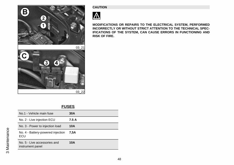
Fuses (03_20, 03_21, 03_22)
The electrical system is equipped with:
1. six protection fuses «A» located in the glove compartment to the left
2. two fuses «B» located under the helmet compartment under the saddle hinge latch.
3. two fuses «C» located under the helmet compartment on the side fairing.
The chart shows the position and characteristics of the fuses in the vehicle.
CAUTION
BEFORE REPLACING THE BLOWN FUSE, FIND AND SOLVE THE FAILURETHAT CAUSED IT TO BLOW. NEVER TRY TO REPLACE THE FUSE WITH ANYOTHER MATERIAL (E.G., A PIECE OF ELECTRIC WIRE).
47
3 Maintenance
03_21
03_22
CAUTION
MODIFICATIONS OR REPAIRS TO THE ELECTRICAL SYSTEM, PERFORMEDINCORRECTLY OR WITHOUT STRICT ATTENTION TO THE TECHNICAL SPEC-IFICATIONS OF THE SYSTEM, CAN CAUSE ERRORS IN FUNCTIONING ANDRISK OF FIRE.
FUSESNo.1 - Vehicle main fuse 30A
No. 2 - Live injection ECU 7.5 A
No. 3 - Power to injection load 10A
No. 4 - Battery-powered injectionECU
7,5A
No. 5 - Live accessories andinstrument panel
10A
48
3 M
aint
enan
ce

No. 6 - Live light remote control andhorn
7.5 A
No. 7 - Live Headlight and SaddleOpening Switch
15 A
No. 8 - Battery-poweredAccessories and Instrument panel
10A
No. 9 - Live Stop light and Starterkey
7.5 A
No. 10 - Power to tail light andinstrument panel lighting
7.5 A
BULBSLow-/ high-beam light 55/60 - 12V (Quantity 1)
Front position light 5W - 12V (Quantity 2)
Instrument Panel warning lights 1.2W - 12V (Quantity 5)
Front turn indicator light 5W - 12V (Quantity 4)
Rear turn indicator light 10W - 12V (Quantity 2)
Rear tail light 5W - 12V (Quantity 1)
Stop Light 16W - 12V (Quantity 1)
License Plate Light 5W - 12V (Quantity 1)
49
3 Maintenance

03_23
03_24
03_25
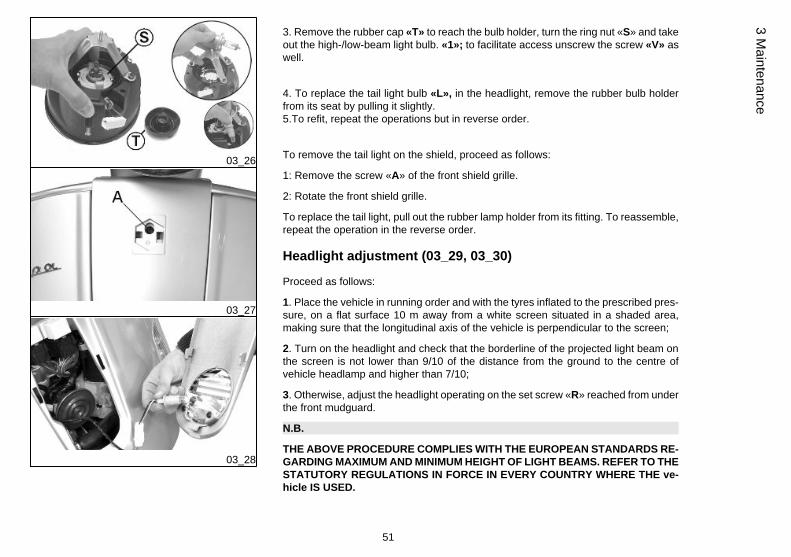
Front light group (03_23, 03_24, 03_25, 03_26, 03_27, 03_28)
WARNING
THE TWIN-FILAMENT (HIGH-BEAM AND LOW-BEAM) BULB IS HALOGEN: DONOT TOUCH THE BULB WITH YOUR FINGERS TO AVOID COMPROMISING ITSFUNCTIONING
N.B.
IF MISTING IS NOTICED ON THE INSIDE OF THE HEADLAMP GLASS, THISDOES NOT INDICATE A FAULT AND IS RELATED TO THE HUMIDITY AND/ORTO LOW TEMPERATURES.
THE PHENOMENON SHOULD QUICKLY DISAPPEAR WHEN THE LIGHT ISSWITCHED ON.
THE PRESENCE OF DROPS OF WATER, ON THE OTHER HAND, COULD INDI-CATE THAT WATER IS INFILTRATING. CONTACT THE PIAGGIO AFTER-SALESSERVICE NETWORK.
Electric characteristicBulbs
1 bulb, 12V/55-60W, for high- and low-beam lights
2 bulbs, 12V/5W, for taillights
To remove the front light assembly, proceed as follows:
1: Remove the nut «B» fixing the headlight to the mudguard.
2: Remove the headlight being careful with the set screw «R», then unhook the con-nectors of the electrical system.
50
3 M
aint
enan
ce
03_26
03_27
03_28
3. Remove the rubber cap «T» to reach the bulb holder, turn the ring nut «S» and takeout the high-/low-beam light bulb. «1»; to facilitate access unscrew the screw «V» aswell.
4. To replace the tail light bulb «L», in the headlight, remove the rubber bulb holderfrom its seat by pulling it slightly.5.To refit, repeat the operations but in reverse order.
To remove the tail light on the shield, proceed as follows:
1: Remove the screw «A» of the front shield grille.
2: Rotate the front shield grille.
To replace the tail light, pull out the rubber lamp holder from its fitting. To reassemble,repeat the operation in the reverse order.
Headlight adjustment (03_29, 03_30)
Proceed as follows:
1. Place the vehicle in running order and with the tyres inflated to the prescribed pres-sure, on a flat surface 10 m away from a white screen situated in a shaded area,making sure that the longitudinal axis of the vehicle is perpendicular to the screen;
2. Turn on the headlight and check that the borderline of the projected light beam onthe screen is not lower than 9/10 of the distance from the ground to the centre ofvehicle headlamp and higher than 7/10;
3. Otherwise, adjust the headlight operating on the set screw «R» reached from underthe front mudguard.
N.B.
THE ABOVE PROCEDURE COMPLIES WITH THE EUROPEAN STANDARDS RE-GARDING MAXIMUM AND MINIMUM HEIGHT OF LIGHT BEAMS. REFER TO THESTATUTORY REGULATIONS IN FORCE IN EVERY COUNTRY WHERE THE ve-hicle IS USED.
51
3 Maintenance

03_29
03_30
03_31
Front direction indicators (03_31)
To replace the front turn indicator bulbs, remove the tail light taking out the retainingscrew "A", remove the bulb holder from its fitting; gently turn the bulb around 30º andremove it. Follow the process in reverse order to refit.
52
3 M
aint
enan
ce

03_32
Rear optical unit (03_32)
Remove screw «A» to remove the rear headlight assembly.
Access to taillight bulbs, stop light bulb and license plate bulb.
To reassemble, repeat the operation in the reverse order.
N.B.
IF MISTING IS NOTICED ON THE INSIDE OF THE HEADLAMP GLASS, THISDOES NOT INDICATE A FAULT AND IS RELATED TO THE HUMIDITY AND/ORTO LOW TEMPERATURES.
THE PHENOMENON SHOULD QUICKLY DISAPPEAR WHEN THE LIGHT ISSWITCHED ON.
THE PRESENCE OF DROPS OF WATER, ON THE OTHER HAND, COULD INDI-CATE THAT WATER IS INFILTRATING. CONTACT THE PIAGGIO AFTER-SALESSERVICE NETWORK.
03_33
Rear turn indicators (03_33)
To gain access to the turn indicator bulbs, remove the fastening screws «E».The bulbs have a bayonet coupling, to remove them press gently and twist anticlock-wise about 30°. To refit follow the same steps but in reverse order.
Rear-view mirrors
Adjust the mirrors by applying slight pressure to the side of the mirror to move it to thedesired position.
53
3 Maintenance

03_34
03_35
Front and rear disc brake (03_34, 03_35)
The brake disc and pad wear is automatically compensated, therefore it has no effecton the functioning of the front and rear brakes. For this reason it is not necessary toadjust the brakes. An excessively elastic brake lever stroke may indicate the presenceof air in the braking circuit or a failure in the braking system. In this case, mainly dueto the importance of brakes to guarantee safe riding conditions, the vehicle should betaken to an Authorised Service Centre or Dealer.
CAUTION
THE BRAKING ACTION SHOULD BEGIN AFTER ABOUT 1/3 OF THE BRAKELEVER STROKE.
CAUTION
HAVE THE BRAKE PADS CHECKED BY THE DEALER ACCORDING TO THECHECKS SPECIFIED IN THE SCHEDULED MAINTENANCE TABLE. HOWEVER,IN THE EVENT OF NOISES COMING FROM THE FRONT AND/OR REAR BRAKESYSTEM DURING OPERATION, IT IS ADVISABLE TO HAVE THE BRAKE SYS-TEM CHECKED BY A PIAGGIO DEALER OR AUTHORISED SERVICE CENTRE.AFTER REPLACING THE BRAKE PADS, DO NOT USE THE SCOOTER UNTILYOU HAVE OPERATED THE BRAKE LEVER SEVERAL TIMES IN ORDER TOALLOW THE PLUNGERS TO SETTLE AND THE LEVER STROKE TO BE SET TOTHE CORRECT POSITION.
CAUTION
THE PRESENCE OF SAND, MUD, SNOW MIXED WITH SALT, ETC. ON THEROAD, CAN DRASTICALLY REDUCE THE DURATION OF THE BRAKE PADS. IN
54
3 M
aint
enan
ce
ORDER TO AVOID THIS, WE RECOMMEND WASHING THE VEHICLE FRE-QUENTLY WHEN RIDING IN THESE ROAD CONDITIONS.
03_36
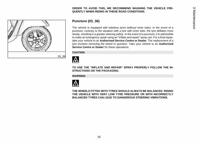
Puncture (03_36)
The vehicle is equipped with tubeless tyres (without inner tube). In the event of apuncture, contrary to the situation with a tyre with inner tube, the tyre deflates moreslowly, resulting in a greater steering safety. In the event of a puncture, it is admissibleto make an emergency repair using an "inflate and repair" spray can. For a final repair,take your vehicle to an Authorised Service Centre or Dealer. The replacement of atyre involves removing the wheel in question. Take your vehicle to an AuthorisedService Centre or Dealer for these operations.
CAUTION
TO USE THE "INFLATE AND REPAIR" SPRAY PROPERLY FOLLOW THE IN-STRUCTIONS ON THE PACKAGING.
WARNING
THE WHEELS FITTED WITH TYRES SHOULD ALWAYS BE BALANCED. RIDINGTHE VEHICLE WITH VERY LOW TYRE PRESSURE OR WITH INCORRECTLYBALANCED TYRES CAN LEAD TO DANGEROUS STEERING VIBRATIONS.
55
3 Maintenance

03_37
Periods of inactivity (03_37)
We recommend carrying out the following operations:
1. Clean the scooter thoroughly and then cover it with a canvas;
2. With the engine off and the piston in the bottom dead centre position, remove thespark plug, and pour into its hole 1 t0 2 cc of the recommended oil. Operate the starterbutton 1-2 times for roughly 1 second to turn the engine over slowly, then insert thespark plug again;
3. Ensure that the fuel tank is at least half full (in order to ensure the total im-mersion of the fuel pump); spread antirust grease on the unpainted metal parts;keep the wheels lifted above the ground by resting the chassis on two wooden wedges;4. As regards the battery, follow the instructions in the "Battery" section.
Recommended productsAGIP CITY HI TEC 4T
Oil to lubricate flexible transmissions (throttle control)Oil for 4-stroke engines
03_38
Cleaning the vehicle (03_38)
Use a low pressure water jet in order to soften the dirt and mud deposited on paintedsurfaces. Once softened, mud and dirt must be removed with a soft sponge for body-work soaked in lots of water and shampoo (2-4% of shampoo in water). Then rinseabundantly with water, and dry with a shammy cloth. Any polishing with silicon waxmust always be preceded by washing
WARNING
IF THE SCOOTER IS USED ON DUSTY ROADS IT IS NECESSARY TO SERVICETHE TRANSMISSION COVER FILTER SPONGE MORE FREQUENTLY.
56
3 M
aint
enan
ce

CAUTION
DETERGENTS CAN POLLUTE WATER. THE VEHICLE MUST BE WASHED AT AWASH STATION EQUIPPED WITH A SPECIAL WATER PURIFICATION SYSTEM.
WARNING
THE USE OF A HIGH-PRESSURE WATER JET IS STRONGLY DISCOURAGEDFOR ANY ENGINE CLEANING OPERATION; HOWEVER, IF NO OTHER MEANSARE AVAILABLE, IT IS THEN NECESSARY TO:• ONLY USE FANLIKE SPRAY JETS.• DO NOT PLACE THE WATER JET NOZZLE CLOSER THAN 60 CM.• DO NOT USE WATER AT TEMPERATURES OVER 40°C.• DO NOT USE HIGH-PRESSURE WATER JETS.• DO NOT STEAM WASH.• DO NOT DIRECT THE JET STRAIGHT TO THE WIRING AND SLOT DIFFUSERON THE TRANSMISSION COVER.
WARNING
NEVER WASH THE SCOOTER IN DIRECT SUNLIGHT, ESPECIALLY DURINGSUMMER WHEN THE BODYWORK IS STILL HOT, AS THE SHAMPOO CAN DAM-AGE THE PAINTWORK IF IT DRIES BEFORE BEING RINSED OFF. NEVER USECLOTHS SOAKED IN PETROL, DIESEL OIL OR KEROSENE FOR CLEANINGTHE PAINTED OR PLASTIC SURFACES SO AS NOT TO DAMAGE THE LUSTREFINISH OR ALTER THE MECHANICAL PROPERTIES.
CLEANING CHROME-PLATED PARTS
57
3 Maintenance

After cleaning chrome-plated parts, polish them with a specific product for chrome-plated, aluminium or stainless steel surfaces. To prevent corrosion, apply a protectivespray on all the metal surfaces, including chrome- and nickel-plated ones. Apply sprayoil and wax with moderation and make sure to wipe off excess product immediately.
CAUTION
NEVER APPLY OIL AND WAX ON RUBBER AND PLASTIC PARTS.
CAUTION
CHECK THAT THERE IS NO OIL OR WAX ON THE TYRES. BEFORE USING YOURSCOOTER TEST ITS BRAKING EFFICIENCY AND BEHAVIOUR ON A BEND.
STARTING FAILUREEmergency switch in «OFF» Set the switch back to «ON»
Fuse blown Replace the blown fuse and havethe vehicle checked by anAuthorised Service Centre.
IGNITION PROBLEMFaulty spark plug Contact an Authorised Service
Centre.
Faulty ignition / injection controlunit.
Contact an Authorised ServiceCentre.
58
3 M
aint
enan
ce

Faulty coil. Due to the presence ofhigh voltage, this check shouldonly be carried out by an expert.
Contact an Authorised ServiceCentre.
LACK OF COMPRESSIONLoosen spark plug. Screw in the spark plug tightly
Cylinder head loose, piston gasrings worn.
Contact an Authorised ServiceCentre.
Valve stuck Contact an Authorised ServiceCentre.
HIGH CONSUMPTION AND LOW PERFORMANCEAir filter blocked or dirty. Clean with water and shampoo and
impregnate with petrol and specificoil (section «Removing the airfilter»)
INSUFFICIENT BRAKINGGreasy disc. Worn pads. Faultybraking system. Presence of air inthe front and rear brake circuit.
Contact an Authorised ServiceCentre.
59
3 Maintenance

INEFFICIENT SUSPENSIONSShock absorber fault, oil leak, endbuffer damaged; shock absorberpreloading incorrectly set
Contact an Authorised ServiceCentre.
IRREGULAR AUTOMATIC TRANSMISSIONVariator rollers and/or driving beltdamaged
Contact an Authorised ServiceCentre.
60
3 M
aint
enan
ce

Vespa GTV250 i.e.
Chap. 04Technical data
61

04_01
62
4 Te
chni
cal d
ata

TECHNICAL DATA
Engine single-cylinder four stroke
Bore x stroke 72 x 60 mm
Cubic capacity 244.29 cm³
Compression ratio 10.5 - 11.5 : 1
Ignition advance (before TDC) variable (integrated into the ignitionsystem)
Spark plug CHAMPION RG 4 PHP
Max. speed 120 km/h
Valve clearance intake: 0.10 mmdischarge: 0.15 mm
Overall length 1930 mm
Overall width 770 mm
Wheelbase 1370 mm
Overall height 1170 mm
Fuel supply throttle valve dia. 32 mm and singleinjector
Exhaust muffler absorption-type exhaust mufflerwith catalytic converter.
Electronic ignition inductive, high efficiencyintegrated with the injectionsystem, with variable timing andseparate HV coil.
Lubrication Engine lubrication with lobe pump(inside crankcase) controlled by a
63
4 Technical data
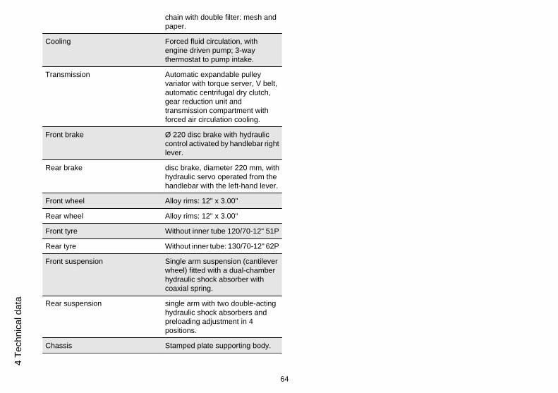
chain with double filter: mesh andpaper.
Cooling Forced fluid circulation, withengine driven pump; 3-waythermostat to pump intake.
Transmission Automatic expandable pulleyvariator with torque server, V belt,automatic centrifugal dry clutch,gear reduction unit andtransmission compartment withforced air circulation cooling.
Front brake Ø 220 disc brake with hydrauliccontrol activated by handlebar rightlever.
Rear brake disc brake, diameter 220 mm, withhydraulic servo operated from thehandlebar with the left-hand lever.
Front wheel Alloy rims: 12" x 3.00"
Rear wheel Alloy rims: 12" x 3.00"
Front tyre Without inner tube 120/70-12" 51P
Rear tyre Without inner tube: 130/70-12" 62P
Front suspension Single arm suspension (cantileverwheel) fitted with a dual-chamberhydraulic shock absorber withcoaxial spring.
Rear suspension single arm with two double-actinghydraulic shock absorbers andpreloading adjustment in 4positions.
Chassis Stamped plate supporting body.
64
4 Te
chni
cal d
ata

Kerb weight 146 ± 5 kg
Maximum admitted weight ~ 340 kg
Petrol tank ~ 9.2 l (approximate value)
Reserve 2÷2.5 l (approximate value)
Engine oil Capacity: 1.3 l (dry) ; 1.2 l (whenchanging oil and filter)
Rear hub oil Capacity approximately 250 cc
Cooling system Capacity: ~ 2.100 ÷ 2.150 l
04_02
Kit equipment (04_02)
One box-spanner for spark plugs; one twin screwdriver; one special spanner for ad-justing the rear shock absorber. The tools are arranged in the front case.
65
4 Technical data

66
4 Te
chni
cal d
ata
Vespa GTV250 i.e.
Chap. 05Spare parts and
accessories
67

05_01
Warnings (05_01)
WARNING
TO PREVENT ACCIDENTS AND TO GUARANTEE PROPER STABILITY, PER-FORMANCE AND SAFETY, RIDE THE VEHICLE VERY CAREFULLY WHEN IT ISFITTED WITH ACCESSORIES OR WITH UNUSUAL LOADS.
WARNING
IT IS ALSO RECOMMENDED THAT "ORIGINAL PIAGGIO SPARE PARTS" BEUSED, AS THESE ARE THE ONLY ONES OFFERING YOU THE SAME QUALITYGUARANTEE AS THOSE INITIALLY FITTED ON THE SCOOTER. THE USE OFNON-ORIGINAL SPARE PARTS RENDERS THE WARRANTY VOID.
WARNING
PIAGGIO MARKETS ITS OWN LINE OF ACCESSORIES THAT ARE RECOG-NISED AND GUARANTEED FOR USE. IT IS THEREFORE ESSENTIAL, IN ORDERTO CHOOSE AND MOUNT THE ACCESSORIES CORRECTLY, TO CONTACT ANAUTHORISED DEALER OR SERVICE CENTRE. THE USE OF NON-ORIGINALACCESSORIES MAY AFFECT THE STABILITY AND OPERATION OF YOUR VE-HICLE AND REDUCE SAFETY LEVELS WITH POTENTIAL RISKS FOR THERIDER.
68
5 Sp
are
parts
and
acc
esso
ries
WARNING
NEVER RIDE THE SCOOTER EQUIPPED WITH ACCESSORIES (TOP BOX AND/OR WINDSHIELD) AT A SPEED HIGHER THAN 100 km/h.
THE SCOOTER CAN BE RIDDEN AT A HIGHER SPEED WITHOUT THE ACCES-SORIES MENTIONED BEFORE WITHIN THE LIMITS ESTABLISHED BY LAW.
IF THERE SHOULD BE NOT-PIAGGIO ACCESSORIES INSTALLED, OR AN AB-NORMAL LOAD, OR IF THE SCOOTER IS NOT IN A GENERALLY GOOD CON-DITION, OR WHENEVER WEATHER CONDITIONS DEMAND IT, SPEED SHOULDBE REDUCED FURTHER.
WARNING
BE EXTREMELY CAREFUL WHEN INSTALLING AND REMOVING THE MECHAN-ICAL ANTITHEFT DEVICE ON THE VEHICLE (U-SHAPED PADLOCK, DISCBLOCK, ETC.).
MAINLY DUE TO THE PROXIMITY TO THE BRAKE PIPES, TRANSMISSIONSAND/OR ELECTRIC CABLES, AN INCORRECT INSTALLATION OR REMOVALOF THE ANTITHEFT DEVICE AS WELL AS LEAVING IT ON BEFORE STARTINGTHE VEHICLE CAN SERIOUSLY DAMAGE ITS COMPONENTS AND AFFECT THECORRECT FUNCTIONING OF THE VEHICLE AND HARM THE USER.
69
5 Spare parts and accessories

70
5 Sp
are
parts
and
acc
esso
ries

Vespa GTV250 i.e.
Chap. 06Programmedmaintenance
71

Scheduled maintenance table
Adequate maintenance is fundamental to ensuring long-lasting, optimum operationand performance of your vehicle.
To this end, a series of checks and maintenance operations (at the owner's expense)have been suggested, which are included in the summary table on the following page.Any minor faults should be reported without delay to an Authorised Service Centreor Dealer without waiting until the next scheduled service to solve it.
All scheduled maintenance services must be carried out at the specified times, evenif the stated mileage has not yet been reached. Carrying out scheduled services ontime is necessary to ensure your warranty remains valid. For any further informationconcerning Warranty procedures and "Scheduled Maintenance", please refer to the"Warranty Booklet".
EVERY 2 YEARSCoolant - change
Brake fluid - change
AFTER 1,000 KMSafety locks - check
Throttle lever - adjustment
Engine oil - change
Electrical system and battery - check
Coolant level - check
Brake fluid level - check
Engine oil - replacement
72
6 Pr
ogra
mm
ed m
aint
enan
ce

Brake pads - check condition and wear
Tyre pressure and wear - check
Vehicle and brake test - road test
Hub oil - change
Steering - Check
AFTER 5,000 KM; 25,000 KM; 35,000 KM; 55,000 KM;65,000 KM
Engine oil - level check/ top-up
Brake pads - check condition and wear
AT 10,000 KM 50,000 KM 70,000 KMSafety locks - check
Throttle lever - adjustment
Air filter - clean
Air filter belt compartment - check
Engine oil - change
Electrical system and battery - check
Coolant level - check
Brake fluid level - check
Engine oil - replacement
Brake pads - check condition and wear
73
6 Programm
ed maintenance

Sliding block / variable speed rollers - change
Tyre pressure and wear - check
Vehicle and brake test - road test
Hub oil - check
Suspensions - check
Steering - Check
AT 15,000 KM 45,000 KM 75,000 KMEngine oil - level check/ top-up
Brake pads - check condition and wear
Driving belt - replacement
AT 20,000 KM; 40,000 KM; 80,000 KMSpark plug - replacement
Throttle lever - adjustment
Air filter - clean
Air filter belt compartment - check
Engine oil - change
Valve clearance - check
Electrical system and battery - check
Coolant level - check
Brake fluid level - check
74
6 Pr
ogra
mm
ed m
aint
enan
ce
Engine oil - replacement
Brake pads - check condition and wear
Sliding block / variable speed rollers - change
Tyre pressure and wear - check
Vehicle and brake test - road test
Hub oil - change
Suspensions - check
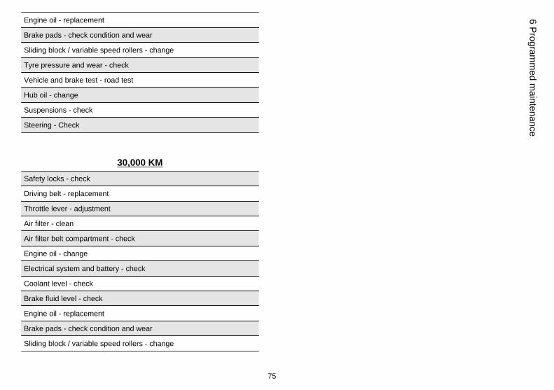
Steering - Check
30,000 KMSafety locks - check
Driving belt - replacement
Throttle lever - adjustment
Air filter - clean
Air filter belt compartment - check
Engine oil - change
Electrical system and battery - check
Coolant level - check
Brake fluid level - check
Engine oil - replacement
Brake pads - check condition and wear
Sliding block / variable speed rollers - change
75
6 Programm
ed maintenance

Tyre pressure and wear - check
Vehicle and brake test - road test
Hub oil - check
Suspensions - check
Steering - Check
60,000 KMSpark plug - replacement
Driving belt - replacement
Throttle lever - adjustment
Air filter - clean
Air filter belt compartment - check
Engine oil - change
Valve clearance - check
Electrical system and battery - check
Coolant level - check
Brake fluid level - check
Engine oil - replacement
Brake pads - check condition and wear
Sliding block / variable speed rollers - change
Tyre pressure and wear - check
Vehicle and brake test - road test
76
6 Pr
ogra
mm
ed m
aint
enan
ce

Hub oil - change
Suspensions - check
Steering - Check
RECOMMENDED PRODUCTS TABLEProduct Description Specifications
AGIP ROTRA 80W-90 Rear hub oil SAE 80W/90 Oil that exceeds therequirements of API GL3 specifications
AGIP CITY HI TEC 4T Oil to lubricate flexible transmissions (throttlecontrol)
Oil for 4-stroke engines
AGIP FILTER OIL Oil for air filter sponge Mineral oil with specific additives for increasedadhesiveness
AGIP GP 330 Grease for brake levers, throttle White calcium complex soap-based spraygrease with NLGI 2; ISO-L-XBCIB2
AGIP CITY HI TEC 4T Engine oil SAE 5W-40, API SL, ACEA A3, JASO MASynthetic oil
AGIP BRAKE 4 Brake fluid FMVSS DOT 4 Synthetic fluid
SPECIAL AGIP PERMANENT fluid coolant Monoethylene glycol-based antifreeze fluid,CUNA NC 956-16
77
6 Programm
ed maintenance

78
6 Pr
ogra
mm
ed m
aint
enan
ce

TABLE OF CONTENTS
AAir filter: 40
BBattery: 44, 45Brake: 43, 54
CClock: 9
DDisc brake: 54
EEngine oil: 34, 35Engine stop: 12
FFuel: 15Fuses: 47
HHeadlight: 51Horn: 11Hub oil: 36
IIdentification: 18Immobilizer: 12, 14Instrument panel: 8
KKey switch: 9Keys: 12
LLight switch: 11
MMaintenance: 33, 71, 72Mirrors: 53
SSaddle: 16, 17Scheduled maintenance: 72Shock absorbers: 25Spark plug: 39Stand: 28Start-up: 11
TTank: 15Technical Data: 61Top box: 19Transmission: 29
Turn indicators: 53Tyre pressure: 24Tyres: 38
79

The descriptions and illustrations given in this publication are not binding. While the basic features as described and illustrated in this manual remainunchanged, PIAGGIO - GILERA reserves the right, at any time and without being required to update this publication beforehand, to make any changesto components, parts or accessory supplies, which it considers necessary to improve the product or which are required for manufacturing or constructionreasons.
Not all versions shown in this publication are available in all Countries. The availability of individual versions should be confirmed with the official Piaggio sales network.
"© Copyright 2007 - PIAGGIO & C. S.p.A. Pontedera. All rights reserved. Reproduction of this publication in whole or in part is prohibited."
PIAGGIO & C. S.p.A. - After-Sales
V.le Rinaldo Piaggio, 23 - 56025 PONTEDERA (Pi)