Embed Size (px)
Citation preview
Vertical Turbine &Submersible Pumps
ISO 9001-2008
Applications
Municipal Water Supply
Industrial
Agricultural
Waste Water
Booster System
Hydrocarbon Transfer
Mine Dewatering
Offshore Platform
Building Trades - (HVAC)
Cooling Towers
Turf Irrigation
Pulp and Paper Mill
Water Amusement Parks
Snow Making
Fish Hatcheries
Barge UnloadingAppli
cati
on
sVertical Turbine &Submersible Pumps
1
Other Features:
Capacity with no limit
Drive options
-Electric motors with variable speed
-Engines with right angle gearbox
-Belt and pulley
Provides high Total Dynamic Head (TDH) and flow rates with high efficiency
•
•
•
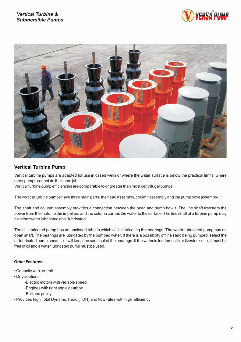
Vertical Turbine Pump
Vertical turbine pumps are adapted for use in cased wells or where the water surface is below the practical limits, where
other pumps cannot do the same job.
Vertical turbine pump efficiencies are comparable to or greater than most centrifugal pumps.
The vertical turbine pumps have three main parts: the head assembly, column assembly and the pump bowl assembly.
The shaft and column assembly provides a connection between the head and pump bowls. The line shaft transfers the
power from the motor to the impellers and the column carries the water to the surface. The line shaft of a turbine pump may
be either water lubricated or oil lubricated.
The oil lubricated pump has an enclosed tube in which oil is lubricating the bearings. The water-lubricated pump has an
open shaft. The bearings are lubricated by the pumped water. If there is a possibility of fine sand being pumped, select the
oil lubricated pump because it will keep the sand out of the bearings. If the water is for domestic or livestock use, it must be
free of oil and a water lubricated pump must be used.
2
Vertical Turbine &Submersible Pumps
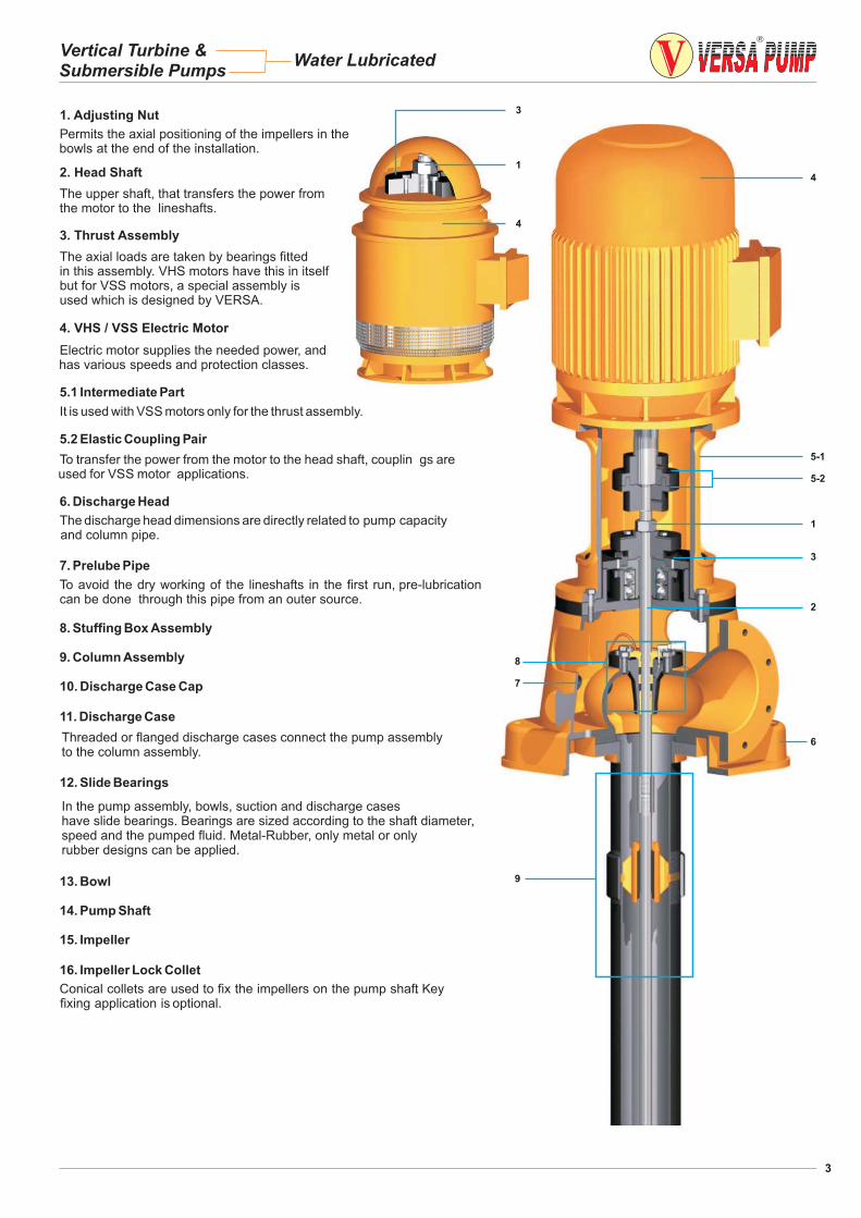
Permits the axial positioning of the impellers in thebowls at the end of the installation.
2. Head Shaft
The upper shaft, that transfers the power fromthe motor to the lineshafts.
3. Thrust Assembly
The axial loads are taken by bearings fittedin this assembly. VHS motors have this in itselfbut for VSS motors, a special assembly isused which is designed by VERSA.
4. VHS / VSS Electric Motor
Electric motor supplies the needed power, andhas various speeds and protection classes.
5.1 Intermediate Part
It is used with VSS motors only for the thrust assembly.
5.2 Elastic Coupling Pair
To transfer the power from the motor to the head shaft, couplin gs areused for VSS motor applications.
6. Discharge Head
The discharge head dimensions are directly related to pump capacityand column pipe.
7. Prelube Pipe
To avoid the dry working of the lineshafts in the first run, pre-lubricationcan be done through this pipe from an outer source.
8. Stuffing Box Assembly
9. Column Assembly
10. Discharge Case Cap
11. Discharge Case
12. Slide Bearings
13. Bowl
14. Pump Shaft
15. Impeller
16. Impeller Lock Collet
Conical collets are used to fix the impellers on the pump shaft. Keyfixing application is optional.
1
4
5-1
5-2
1
3
2
6
4
8
7
9
31. Adjusting Nut
In the pump assembly, bowls, suction and discharge caseshave slide bearings. Bearings are sized according to the shaft diameter,speed and the pumped fluid. Metal-Rubber, only metal or onlyrubber designs can be applied.
Threaded or flanged discharge cases connect the pump assemblyto the column assembly.
3
Vertical Turbine &Submersible Pumps
Water Lubricated
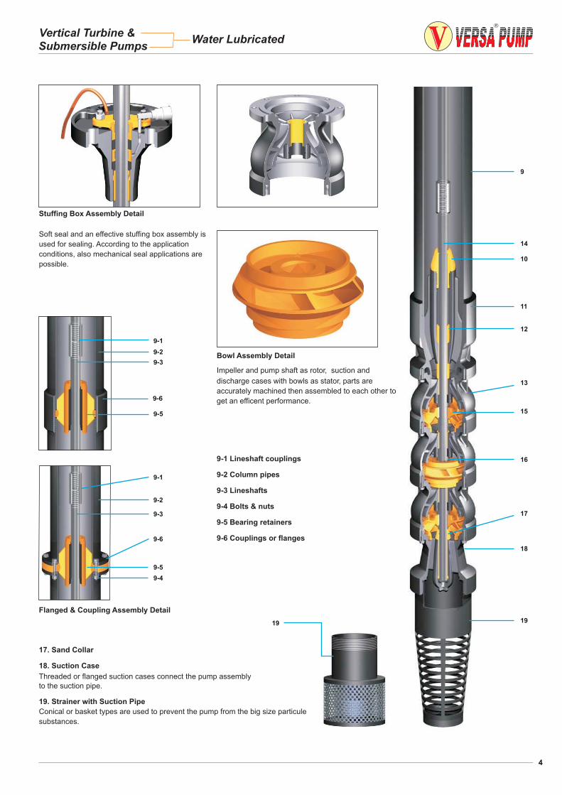
9-1 Lineshaft couplings
9-2 Column pipes
9-3 Lineshafts
9-4 Bolts & nuts
9-5 Bearing retainers
9-6 Couplings or flanges
Soft seal and an effective stuffing box assembly is
used for sealing. According to the application
conditions, also mechanical seal applications are
possible.
Stuffing Box Assembly Detail
Impeller and pump shaft as rotor, suction and
discharge cases with bowls as stator, parts are
accurately machined then assembled to each other to
get an efficent performance.
Bowl Assembly Detail
17. Sand Collar
18. Suction Case
Threaded or flanged suction cases connect the pump assembly
to the suction pipe.
19. Strainer with Suction Pipe
Conical or basket types are used to prevent the pump from the big size particule
substances.
19
9
14
12
15
16
18
17
19
10
11
13
Flanged & Coupling Assembly Detail
9-1
9-2
9-3
9-6
9-5
9-4
4
Vertical Turbine &Submersible Pumps
Water Lubricated
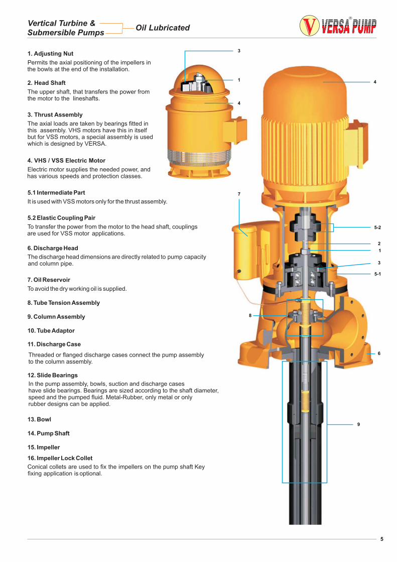
1. Adjusting Nut
Permits the axial positioning of the impellers inthe bowls at the end of the installation.
2. Head Shaft
The upper shaft, that transfers the power fromthe motor to the lineshafts.
3. Thrust Assembly
The axial loads are taken by bearings fitted inthis assembly. VHS motors have this in itselfbut for VSS motors, a special assembly is usedwhich is designed by VERSA.
4. VHS / VSS Electric Motor
Electric motor supplies the needed power, andhas various speeds and protection classes.
5.1 Intermediate Part
It is used with VSS motors only for the thrust assembly.
5.2 Elastic Coupling Pair
To transfer the power from the motor to the head shaft, couplingsare used for VSS motor applications.
7. Oil Reservoir
To avoid the dry working oil is supplied.
8. Tube Tension Assembly
9. Column Assembly
10. Tube Adaptor
11. Discharge Case
12. Slide Bearings
13. Bowl
14. Pump Shaft
15. Impeller
1
4
3
4
5-1
1
8
7
2
6
9
3
5-2
6. Discharge Head
The discharge head dimensions are directly related to pump capacityand column pipe.
Threaded or flanged discharge cases connect the pump assemblyto the column assembly.
In the pump assembly, bowls, suction and discharge caseshave slide bearings. Bearings are sized according to the shaft diameter,speed and the pumped fluid. Metal-Rubber, only metal or onlyrubber designs can be applied.
16. Impeller Lock Collet
Conical collets are used to fix the impellers on the pump shaft. Keyfixing application is optional.
5
Vertical Turbine &Submersible Pumps
Oil Lubricated
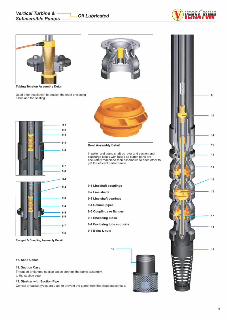
Used after installation to tension the shaft enclosingtubes and the sealing.
Tubing Tension Assembly Detail
9-1 Lineshaft couplings
9-2 Line shafts
9-3 Line shaft bearings
9-4 Column pipes
9-5 Couplings or flanges
9-6 Enclosing tubes
9-7 Enclosing tube supports
9-8 Bolts & nuts
Impeller and pump shaft as rotor and suction anddischarge cases with bowls as stator, parts areaccurately machined then assembled to each other toget the efficent performance.
Bowl Assembly Detail
9
10
14
16
15
18
17. Sand Collar
18. Suction Case
Threaded or flanged suction cases connect the pump assembly
to the suction pipe.
19. Strainer with Suction Pipe
Conical or basket types are used to prevent the pump from the sized substances.
19
Flanged & Coupling Assembly Detail
9-1
9-2
9-3
9-4
9-5
9-7
9-6
9-1
9-2
9-3
9-4
9-5
9-7
9-6
9-8
6
11
12
13
17
19
Vertical Turbine &Submersible Pumps
Oil Lubricated