Embed Size (px)
Citation preview

ROMI DCM 620 SERIESVERtIcal MachInIng cEntERS - 5-axIS / 5-SIdEd
| ROMI dcM 620-5x | ROMI dcM 620-5F

2
ROMI Industrial complex, in Santa Bárbara d’Oeste - SP, Brazil
INNOVATION + QUalItY
ROMI: Since 1930 producing high technology. Since its foundation, the company is recognized by its focus on creating products and innovative solutions which guarantees its technological leadership among big manufacturers of machine tools market. ROMI industrial complex is among the most modern and productive ones in the segments of machine tools, plastic processing machines and cast iron parts of high quality.
Continuous investments in Research & Development result in products with state-of-the-art technology. the high technology applied to Romi machines offer highly reliable products, with high accuracy, efficiency and great flexibility for several types of machining processes. Romi R&d is focused on increasing competitiveness for its customers.
Present throughout Brazil and in over 60 countries.Romi covers all domestic territory through its sales subsidiaries network fully prepared to support customers supplying an extensive range of services from marketing to after sales.International market is covered by its subsidiaries located in United States, Mexico and Europe and also by its dealers network located in strategic logistic centers around the globe completely capable for serving customers in 5 continents.

3
High technology for complex geometries, best machining strategy choice and productivity increase.
ROMI dcM 620 Series consists of advanced vertical machining center of 5-axis / 5-sided, designed for machining simple and complex geometry parts with high speeds. the machining configuration with 5-axis simultaneous or 5-sided allows machining complex parts in a single setup, significantly reducing machining time with efficiency, precision and productivity.
ROMI DCM 620 SERIES
Plant 16
| ROMI dcM 620-5F | ROMI dcM 620-5x

4
Power Graph Machine dimensionsdimensions in mm (in)
24 / 18
hp / kW
Ratin
gS6
- 40
% -
10 m
in
ROMI DCM 620-5X
9 / 7
2.30
0
4.60
0
12.0
00
75 N.m(55 lbf.ft)
rpm
24 / 18
hp / kW
Ratin
gS6
- 40
% -
10 m
in
ROMI DCM 620-5F
9 / 7
2.30
0
5.00
0
10.0
00
73,2 N.m(54 lbf.ft)
rpm
1,20
0 (4
7)
1,080 (43) 2,255 (89)835 (33)
1,018 (40)Door opening
755
(30)
2,41
1 (9
5)3,
062
(121
)
2,732 (108) 275
(10,
8)
Ø 930 (37) (DCM 620-5X)Ø 720 (28) (DCM 620-5F)
R 1,265 (50)
(DCM 620-5X)
R 1,158 (46)
(DCM 620-5F)
4,440 (175) (DCM 620-5X) / 4,335 (171) (DCM 620-5F)2,335 (92)
3,58
5 (1
41) (
DCM
620
-5X)
/ 3,
477
(137
) (DC
M 6
20-5
F)2,
590
(102
)
Flexibility, efficiency, accuracy and productivity for machining parts in one single set-up.
ROMI DCM 620-5X • headstock: 12.000 rpm • Spindle taper: ISO 40 • Main motor: 24 hp / 18 kW • automatic tool changer: 32 tools capacity • Rotary table: Ø 650 mm (26”) / Ø 500 mm (20”) • cnc Siemens Sinumerik 840d
ROMI DCM 620-5F • headstock: 10.000 rpm • Spindle taper: ISO 40 • Main motor: 24 hp / 18 kW • automatic tool changer: 30 tools capacity • Rotary table: 600 mm • cnc Siemens Sinumerik 828d
ROMI DCM 620-5F / DCM 620-5X

5
STRUCTURE
1
7
6
2
3
4 5 8
ROMI DCM 620-5X Structure
1 Automatic tool changer Fast and accurate automatic tool changer with 30 tools capacity (ROMI dcM 620-5F) and 32 tools capacity (ROMI dcM 620-5x).
2 Headstock Spindle cartridge is directly coupled to the main motor (direct drive) with great efficiency in power and torque transmission. It presents the advantages of low noise and elimination of gaps and vibrations if compared with pulleys and belt transmission system. Offers maximum rotation of 10,000 rpm (ROMI dcM 620-5F and 12,000 rpm (ROMI dcM 620-5x, ensuring excellent performance under severe cutting conditions in machining operations at full power.
3 Support bearing It assures complete rigidity of the table in operations with heavy loads.
4 Rotary table (C axis) It enables pieces positioning in any part of the table, 360°.
5 Tilting table (B axis) It supports the rotary table and enable its positioning from -110° up to +110° (*) (ROMI dcM 620-5F) and -50° up to +110° (ROMI dcM 620-5x).
6 Column With robust structure it supports the headstock assembly. the column is supported on linear roller guides which offers high rigidity and enables high speed displacements.
7 Main motor It is directly coupled to the spindle cartridge ensuring great efficiency in power and torque transmission.
8 Base It is robust and made of cast iron. It supports the table assembly, comprised of B and c axes, column assembly and headstock assembly. x, Y and Z axes have linear roller guides which offer high rigidity, stability, positioning accuracy and high quality surface finishing for machining processes with maximum efficiency and productivity.
(*) Machines equipped with tool preset the angle becomes -50°.

6
B axis
C axis
Work area ROMI DCM 620-5F
ROTARY AND TILTING axES
B axis tilt: 0°
B axis tilt: -50°
B axis tilt: +110°
Rotary axis (C axis) and tilting axis (B axis) ROMI DCM 620-5F
Rotary / tilting table offers high rigidity, assuring great precision in 5 faces machining with millesimal angular positioning to achieve the result of very precise high complexity parts.
B and C axes characteristics
• B axis tilting angle: - 110° to +110° (*)• c axis rotary angle: 360°• B and c axes are driven by independent motors• Maximum weight allowed on the table
(B and c axes): 300 kg (660 lbs)• B and c axes rotation: 12 rpm• clamping force: B axis = 4.410 n.m
c axis = 2.450 n.m
Rotary axis (C axis) and tilting axis (B axis)
Rotary / tilting table offers high rigidity. It is equipped with linear encoders assuring great precision in simultaneous machining of 5 axes, with millesimal angular positioning, to achieve the result of very precise high complexity parts.
B and C axes characteristics
• B axis tilting angle: -50° to +110°• c axis rotary angle: 360°• B and c axes are driven by independent motors• Maximum weight allowed on the table
(B and c axes): 300 kg (660 lbs)• B and c axes rotation: 25 rpm• clamping force: B axis = 4.410 n.m
c axis = 2.450 n.m
(*) Machines equipped with tool preset the angle becomes -50°.

7
Headstock cooling system
Spindle cartridge and clamping flange, between the motor and the cartridge, are cooled by a fluid recirculating system specific for the headstock to ensure thermal and geometric stability for the assembly. headstock housing has a chamber which involves the cartridge housing for cooling fluid circulation. cooling system is comprised of one cooling unit (heat - fluid air exchanger) which enables the circulation of cooling fluid in headstock housing to remove
all heating generated by spindle roller bearings. the system reduces the variation of temperature between headstock and immediate surroundings so that the headstock temperature is kept as similar as possible to the ambient temperature. the great benefit of the headstock cooling system is the minimization of thermal distortions of the housing and the assurance of perfect alignment of spindle center line in machining operations which demand high precision of Z axis positioning.
HEADSTOCk
Headstock
12.000 rpm direct drive spindle eliminates noises, gaps and vibration problems that can usually occur in pulleys and belt transmission system. It ensures efficiency in power transmission and also brings improvements for the quality of rigid tapping operations.
Excellent thermal insulation project
thermal insulation system of the headstock minimizes displacements caused by heating offering high precision spindle positioning and long durability for the assembly. coupling between motor and spindle is also isolated, and combined with headstock cooling system, thermal distortions are minimized.

8
LINEAR ROLLER gUIdES
Linear scale (optional)
x, Y and Z axes can be equipped with linear scale (optional). It provides machine with high precision and repeatability of axes positioning required in machining processes of high complexity parts.
It provides a direct reading of the position where the axis is and send relative signals to the cnc. the reading is real and direct so there is no interference of any possible ball screw error caused by heating or expansion.
they offer high load capacity, rigidity and stability even under severe machining conditions. they also enable fast displacements and high accelerations with precision due to low friction coefficient between rails and blocks.
Linear guides benefits
• high rigidity, high load capacity, long durability• Fast axes positioning minimizing idle
time and improving productivity• coolant oil low consumption• Easy maintenance
Automatic tool changer
atc system offers fastness and reliability in tools change. It has a magazine for Bt / BBt 40 holders with 30 tools capacity (ROMI dcM 6205F) and 32 tools capacity (ROMI dcM 620-5x). In order to facilitate tools loading and unloading the machine can be equipped with a lateral door for access to the magazine and an operation panel for manual movement of tools magazine.

9
Measure / Inspection of Parts and Optical Receiver System (optional)
this system allows the user to reduce workpieces setup time, as well as the inspection process, leaving a larger time for machining workpieces effectively.
after a part or device measurement performed, the machine itself performs a self-alignment, because the references of the part program can be rotated according to the position informed read by probe and informed to the cnc.
Enables inspection during machining process to monitor the dimensional and workpiece position, performing an automatic correction if necessary.
datUM SPHERE and tOUch PROBE
Datum Sphere (optional)
It is a effective solution for checking alignment and positioning of rotary axes performance. In just minutes, the machine can identify and notify deficient alignments and geometry which can cause non-compliance of workpieces.
10
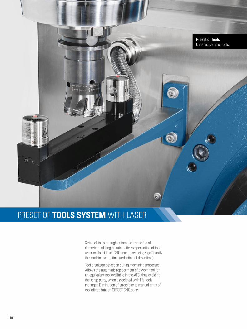
PRESEt OF TOOLS SYSTEM WIth laSER
Preset of Toolsdynamic setup of tools.
Setup of tools through automatic inspection of diameter and length, automatic compensation of tool wear on tool Offset cnc screen, reducing significantly the machine setup time (reduction of downtime).
tool breakage detection during machining processes. allows the automatic replacement of a worn tool for an equivalent tool available in the atc, thus avoiding the scrap parts, when associated with life tools manager. Elimination of errors due to manual entry of tool offset data on OFFSEt cnc page.

11
CNC
Conversational programming programGUIDE
the programgUIdE facilitates program creation thru the input of data in user-friendly screens and animated elements which helps in unequivocal data input. Programming is simplified thru drilling, boring, tapping and milling cycles and free-shape profile cuts.
CNC Siemens Sinumerik 828D (ROMI dcM 620-5F)
cnc Siemens Sinumerik 828d offers 10.4‘‘ lcd color monitor, with softkeys to active and select functions, USB port, drive to compact Flash card and Ethernet interface for factory network, bringing a great flexibility for loading programs and parameters.
CNC Siemens Sinumerik 840D sl (ROMI dcM 620-5x)
cnc Siemens Sinumerik 840d sl offers 15‘‘ lcd color monitor, USB port and Ethernet interface for factory network, bringing a great flexibility for loading programs and parameters.
12
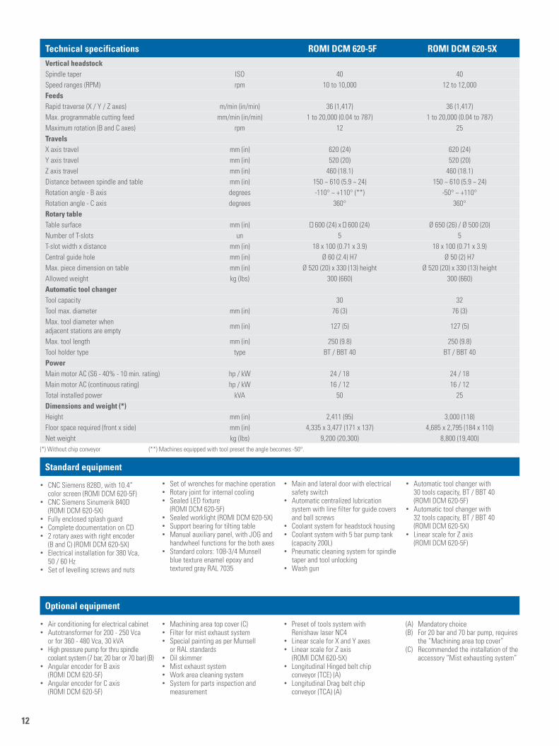
Technical specifications ROMI DCM 620-5F ROMI DCM 620-5XVertical headstockSpindle taper ISO 40 40Speed ranges (RPM) rpm 10 to 10,000 12 to 12,000FeedsRapid traverse (x / Y / Z axes) m/min (in/min) 36 (1,417) 36 (1,417)Max. programmable cutting feed mm/min (in/min) 1 to 20,000 (0.04 to 787) 1 to 20,000 (0.04 to 787)Maximum rotation (B and c axes) rpm 12 25Travelsx axis travel mm (in) 620 (24) 620 (24)Y axis travel mm (in) 520 (20) 520 (20)Z axis travel mm (in) 460 (18.1) 460 (18.1)distance between spindle and table mm (in) 150 ~ 610 (5.9 ~ 24) 150 ~ 610 (5.9 ~ 24)Rotation angle - B axis degrees -110° ~ +110° (**) -50° ~ +110°Rotation angle - c axis degrees 360° 360°Rotary tabletable surface mm (in) 600 (24) x 600 (24) Ø 650 (26) / Ø 500 (20)number of t-slots un 5 5t-slot width x distance mm (in) 18 x 100 (0.71 x 3.9) 18 x 100 (0.71 x 3.9)central guide hole mm (in) Ø 60 (2.4) h7 Ø 50 (2) h7Max. piece dimension on table mm (in) Ø 520 (20) x 330 (13) height Ø 520 (20) x 330 (13) heightallowed weight kg (lbs) 300 (660) 300 (660)Automatic tool changertool capacity 30 32tool max. diameter mm (in) 76 (3) 76 (3)Max. tool diameter when adjacent stations are empty mm (in) 127 (5) 127 (5)
Max. tool length mm (in) 250 (9.8) 250 (9.8)tool holder type type Bt / BBt 40 Bt / BBt 40PowerMain motor ac (S6 - 40% - 10 min. rating) hp / kW 24 / 18 24 / 18Main motor ac (continuous rating) hp / kW 16 / 12 16 / 12total installed power kVa 50 25Dimensions and weight (*)height mm (in) 2,411 (95) 3,000 (118)Floor space required (front x side) mm (in) 4,335 x 3,477 (171 x 137) 4,685 x 2,795 (184 x 110)net weight kg (lbs) 9,200 (20,300) 8,800 (19,400)
Standard equipment
Optional equipment
• cnc Siemens 828d, with 10.4” color screen (ROMI dcM 620-5F)
• cnc Siemens Sinumerik 840d (ROMI dcM 620-5x)
• Fully enclosed splash guard• complete documentation on cd• 2 rotary axes with right encoder
(B and c) (ROMI dcM 620-5x)• Electrical installation for 380 Vca,
50 / 60 hz• Set of levelling screws and nuts
• Set of wrenches for machine operation• Rotary joint for internal cooling• Sealed lEd fixture
(ROMI dcM 620-5F)• Sealed worklight (ROMI dcM 620-5x) • Support bearing for tilting table• Manual auxiliary panel, with JOg and
handwheel functions for the both axes • Standard colors: 10B-3/4 Munsell
blue texture enamel epoxy and textured gray Ral 7035
• Main and lateral door with electrical safety switch
• automatic centralized lubrication system with line filter for guide covers and ball screws
• coolant system for headstock housing• coolant system with 5 bar pump tank
(capacity 200l)• Pneumatic cleaning system for spindle
taper and tool unlocking• Wash gun
• automatic tool changer with 30 tools capacity, Bt / BBt 40 (ROMI dcM 620-5F)
• automatic tool changer with 32 tools capacity, Bt / BBt 40 (ROMI dcM 620-5x)
• linear scale for Z axis (ROMI dcM 620-5F)
• air conditioning for electrical cabinet• autotransformer for 200 - 250 Vca
or for 360 - 480 Vca, 30 kVa• high pressure pump for thru spindle
coolant system (7 bar, 20 bar or 70 bar) (B)• angular encoder for B axis
(ROMI dcM 620-5F)• angular encoder for c axis
(ROMI dcM 620-5F)
• Machining area top cover (c)• Filter for mist exhaust system• Special painting as per Munsell
or Ral standards• Oil skimmer• Mist exhaust system• Work area cleaning system• System for parts inspection and
measurement
• Preset of tools system with Renishaw laser nc4
• linear scale for x and Y axes• linear scale for Z axis
(ROMI dcM 620-5x)• longitudinal hinged belt chip
conveyor (tcE) (a)• longitudinal drag belt chip
conveyor (tca) (a)
(a) Mandatory choice(B) For 20 bar and 70 bar pump, requires
the “Machining area top cover”(c) Recommended the installation of the
accessory “Mist exhausting system”
(*) Without chip conveyor (**) Machines equipped with tool preset the angle becomes -50°.

13
Working layout - ROMI dcM 620-5F - dimensions in mm (in)
Table dimensions - ROMI dcM 620-5F - dimensions in mm (in) Holders - dimensions in mm (in)
drawings are not in scale.
+260 (14.2) -360 (14.2)
620 (24)X axis travel
150
(5.9
) 4
60 (1
8.1)
Z ax
is tr
avel
610
(24)
R 328Max workpiecetravel - B axis
Tabl
e ce
nter
50 (2
.0)
-260 (10.2) +260 (10.2)
520 (20)Y axis travel
[250
(9.8
)]
Ø 340 (13.4)
Ø 520 (20)
330
(13)
80
(3.1)
Max workpiece dimension
321 (12.6)
+110°
B axis travel
321 (12.6)
-110° B axis travel
100
(3.9
)10
0 (3
.9)
100
(3.9
)10
0 (3
.9)
145 (5.7) (4x)
B B
600 (24)
600
(24)
12(0
.47)
18 (0.7
1)
30 (1.18)
18 H7+ 0.018+ 0.000
30 (1
.18)
Ø 60 H7
T-slots detail
Central Ø detail
B-B
+ 0.025+ 0.000
280
(11)
Holder:MAS 403-BT40
Fixing pin:MAS 407-P40T-l
Ø 127 (5) (max.)Without adjacent tools
Ø 76 (3) (max.)With adjacent tools

14
Working layout - ROMI dcM 620-5x - dimensions in mm (in)
Table dimensions - ROMI dcM 620-5x - dimensions in mm (in) Holders - dimensions in mm (in)
drawings are not in scale.
105
(4.1)
100(3.9)
Ø 650(26)
Ø 500(20)10
5(4
.1)
100(3.9)
100(3.9)
100(3.9)
100(3.9)
100(3.9)
100(3.9)
100(3.9)
B B
12(0
.47)
18 (0.71
)
30(1.18)
18 H7+ 0.018+ 0.000
T-slot detail
Central Ø detail
30 (1.1
8)
50 H7
B-B
+ 0.025+ 0.000
280
(11)
Holder:MAS 403-BT40
Fixing pin:MAS 407-P40T-l
Ø 127 (5) (max.)Without adjacent tools
Ø 76 (3) (max.)With adjacent tools
Ø 650 (26)
620 (24)X axis travel
+260 (10.2)-360 (14.2)
+448
(17.
6)
460
(18.
1)Z
axis
trav
el
Ø 500 (20)
150
(5.9
)
-353 (13.9)
+12
(0.4
7)
Tool
cha
nger
posi
tion
Tool changeposition
520 (20)Y axis travel
+260 (10.2)-260 (10.2)
325 (12.8)
+50°
B ax
is tra
vel
322 (12.7)-110°B axis travel
Ø 520 (20)
330
(13)
80 (3.1
)
Ø 342 (13.5)
Max. workpiecedimension

15
Características do CNC - ROMI dcM 620-5F - Siemens 828d
Características do CNC - ROMI dcM 620-5x - Siemens 840d sl
Resources and cnc performance• Monitor 104”• Precision 80bit nanOFP• advanced Surface for
Mold & die applications• Block Execution - ~1 ms• look ahead - 150• acceleration with Jerk control• Pich Error• Synchronous actions
and high Speed Output• Idioms: Portuguese, English,
Spanish, Italian, german, French• Ethernet Interface• USB Interface• cF card Interface• Part number, Machining
cycle time and clock• calculation Function
Programming resources:• directory classified by Program,
Subprogram and cycles• SInUMERIK g code programming
with high-level commands• cycle of technological support
to g-code programs SInUMERIK• Programming machining ShopMill• high-speed settings for applications
of dies and molds• Subprogram call• Program Block Search• Background Editing• Memory Program number = 300• Part Program Storage = 5 MB
Resources and CNC Performance• Resources and cnc Performance• Monitor 15”• 80bit nanO FP• advanced Surface for
Mold & die applications• Block Execution = > 0,5ms• look ahead 250• acceleration with Jerk limitation• Pich Error• Spline Interpolation• Synchronized actions• transformation with cylindrical radius
compensation tool for parallel grooves• USB• Ethernet
MDynamics 5-axis• Simultaneous axis control for 5 axes• advanced Surface - Step II• User Memory on user cF-card• Spline Interpolation• transmit and peripheral
surface transformation• Measuring cycles• 3-d simulation/simultaneous Recording• ShopMill/Shopturn work step programming• detection of residual material• 5 axis Machining Package• 3-d Radius compensation• Measure kinematics• tool center point programming - tRaORI• Orientation smoothing with ORISOn
Programming Resources• SInUMERIK g code programming with
high-level commands for flexible scheduling of medium and large groups of parts
• Programguide: cycle of technological support to g-code programs SInUMERIK
• Programming machining ShopMill: efficient programming for individual pieces and small groups of parts
• Program load / Save• linear, circular and helical Interpolation• Rectangular and circular Bosses Milling• circular Pocket• Rectangular Pocket• Face Milling• Profile Milling• dwell time
Feedrate functions• 4 axes Simultaneous control
(Rotary table is mandatory)• Feedrate in mm/ min or pol / min• Feedrate in mm/ rot or pol / rot• Feedrate and Precision Position on the
corners• Exact stop mode
Graphic functions• Online graphic help• Machining graphic Simulation• Kit graf: 3d simulation / simulation in real
time/ detection of residual material
Coordinate systems• Work Plane Selection• Workpiece coordinate System = 100• Machine coordinate System• Workpiece coordinate System Presetting• local Workpiece coordinate System
Coordinate values and dimensions• Speed and dimension in Inch or Metric• absolute and Incremental
Programming Mode
• Interpreter built-in ISO code• cycles of technology available
for programming and machining Programguide ShopMill
• Boring cycles• Machining cycles for standard geometries• Wide range of standard positions for
machining and boring operations• Write cycle character• high-speed settings for applications
of dies and molds• Machining cycles for contour
pockets / islands with spigots• number / research program• name of program• Sub-program• Program Block Search• Expanded edition• Background Editing• Memory Program number = 500• Part Program Storage= 3MB• Program creation and Editing• Program control• Reference function
Feedrate Functions• Feedrate in mm/min or inch/min• Feedrate in mm/ rot ou pol / rot• dwell time• Feedrate and Precision
Position on the corners• Exact stop mode• cutting Mode• continuous tapping mode
Graphic Functions• animated elements -
support dynamic cycles• 3d simulation / simulation in real time• detection of residual material• Measuring cycles• Quickview die and Mold• 3d simulation for multi-axis machining
• linear and circular Interpolation with Polar coordinates
• Scale factor• Mirror /amirror• coordinate System Rotating• transfer Zero Point
Spindle functions• RPM in S code• Spindle angular Positioning (M19 ou Spos)
Applied tool function• tool Radius compensation• tool length and Radius
Manual Measurement• tool Offset compensation Pairs
(length and diameter) = 512• tool Management• tool life Management
Macro• Parametric Programming• Variables of parametric Programming• System Variables
Simplification program functions• cycle 800 Rotary table• canned cycle for drilling,
Boring and tapping• linear and circular Pattern for drilling• grid Pattern for drilling• circular Pattern for Straight
and circular Slots• circular Pattern for Oblong Milling• canned cycle for Rigid tapping
Coordinate Systems• Work Plane Selection• Workpiece coordinate System
(Machining coordinate System)• local Workpiece coordinate System• Workpiece coordinate System Presetting• Rotation of the coordinate system
Coordinate Values and Dimensions• Programming with decimal point• Speed and dimension in Inch or Metric• absolute and Incremental
Programming Mode• Polar coordinate• Scale factor• Mirror• Programmable data Entry
Spindle Functions• RPM in S code• Spindle angular Positioning (M19 ou Spos)
Applied Tool Function• tool Radius compensation• tool offset length and Radius
Measurement 1500• tool Offset compensation Pairs
(length and diameter)• tool length and Radius
Manual Measurement• tool Management• Function of charge / discharge for simple
allocation magazine
Macro• Parametric Programming• VaRIaBlES of parametric Programming
Simplification Program Functions• canned cycle for drilling,
Boring and tapping• canned cycle for Rigid tapping• chamfering and corner rounding
• canned cycle for thread Milling• Floating tapping• Engraving cycle• Rigid tapping• cylindrical interpolation
(Rotary table is mandatory)
Programming format - 828D• ISO programming format
for the command 828d• Programming ShOPMIll
Execution operations• JOg Mode• handwheel Mode• Mda Operation• automatic Mode• Single Block Mode• Program Stop Mode• Optional Stop Mode• Program test Operation Mode• Block delet Mode• axes Referencing by Program• tool Retract and Repositioning in JOg
Mode (Key REPOS)• Program Restart• automatic Operation by Memory or Remote
Maintenance functions• Emergency Stop• diagnostics and alarms Functions
• Programming in mirror image• cylindrical Interpolation - tRacYl
Programming Format - 840D sl Series• ISO programming format
for the command 840d sl
Execution Operations• Mda Operation• automatic Mode• Single Block Mode• Program Stop Mode• Optional Stop Mode• Block delete Mode• Program restart• Selection of blocks for execution
Maintenance Functions• Emergency Stop• diagnostics and alarms Functions
Energy Control System• control Energy - Efficient
Operation of the Machine

ROM
I dcM
620
-5x
/ In
/ ah
/ 09
2015
- Ill
ustra
tive
phot
os -
Spec
ifica
tions
are
sub
ject
to c
hang
e w
ithou
t prio
r not
ice
- Ple
ase
recy
cle.
W W W . R O M I . c O M
WORLDWIDE PRESENCE
CE safety regulation compliance available only for the European Community or under request.
ROMI - BRaZIl
ROMI - UK
ROMI - gERManYROMI - ItalY
ROMI - FRancE
ROMI - SPaIn
ROMI - MExIcO
ROMI - USa
Indústrias Romi SA Rod. SP 304, Km 141,5 Santa Bárbara d’Oeste SP 13453 900 Brazil Phone +55 (19) 3455 9800 Fax +55 (19) 3455 1030 [email protected]
ROMI Europa GmbH Wasserweg 19 d 64521 gross gerau germany Phone +49 (6152) 8055 0 Fax +49 (6152) 8055 50 [email protected]
ROMI France SAS Parc de genève, 240 Rue Ferdinand Perrier 69800 St Priest Phone +33 4 37 25 60 70 Fax +33 4 37 25 60 71 [email protected]
Burkhardt+Weber Fertigungssysteme GmbH Burkhardt+Weber-Strasse 57 72760 Reutlingen, germany Phone +49 7121 315-0 Fax +49 7121 315-104 [email protected] www.burkhardt-weber.de
ROMI Machine Tools, Ltd 1845 airport Exchange Blvd Erlanger KY - 41018 USa Phone +1 (859) 647 7566 Fax +1 (859) 647 9122 [email protected]
ROMI Machines Uk Limited leigh Road Swift Valley Industrial Estate Rugby cV21 1dS Phone +44 1788 544221 Fax +44 1788 542195 [email protected]
ROMI Máquinas España calle comadrán, 15 Pol. Ind. can Salvatela c.P. 08210 - Barberà del Vallès Phone +34 93 719 4926 Fax +34 93 718 7932 [email protected]
ROMI in Mexico Moliere 13, piso 10-B col. chapultepec Polanco, c.P. 11560 [email protected]
ROMI Italia Srl Via Morigi, 33 - 29020 gossolengo, Piacenza - Italy Phone +39 349 590 0474 [email protected]
Germany - B+WItalyBrazil GermanyUnited States SpainFranceEngland