Embed Size (px)
Citation preview
Presented to: IAMFTWG, Kansas City, MO
By: Robert I. Ochs
Date: June 7 2016
Federal Aviation Administration
Vertical Flame Propagation (VFP)
Test Method Update
Federal Aviation Administration
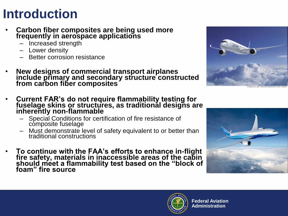
Introduction • Carbon fiber composites are being used more
frequently in aerospace applications – Increased strength – Lower density – Better corrosion resistance
• New designs of commercial transport airplanes include primary and secondary structure constructed from carbon fiber composites
• Current FAR’s do not require flammability testing for
fuselage skins or structures, as traditional designs are inherently non-flammable
– Special Conditions for certification of fire resistance of composite fuselage
– Must demonstrate level of safety equivalent to or better than traditional constructions
• To continue with the FAA’s efforts to enhance in-flight
fire safety, materials in inaccessible areas of the cabin should meet a flammability test based on the “block of foam” fire source
Federal Aviation Administration
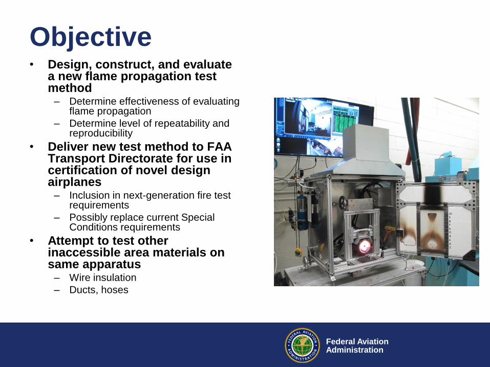
Objective • Design, construct, and evaluate
a new flame propagation test method
– Determine effectiveness of evaluating flame propagation
– Determine level of repeatability and reproducibility
• Deliver new test method to FAA Transport Directorate for use in certification of novel design airplanes
– Inclusion in next-generation fire test requirements
– Possibly replace current Special Conditions requirements
• Attempt to test other inaccessible area materials on same apparatus
– Wire insulation
– Ducts, hoses
Federal Aviation Administration
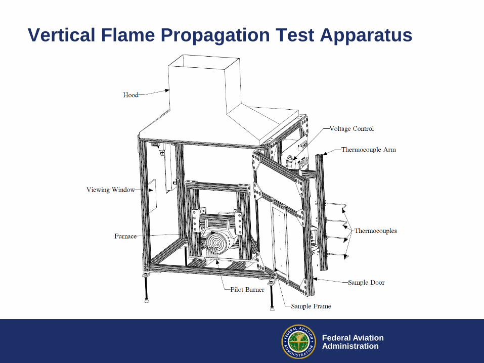
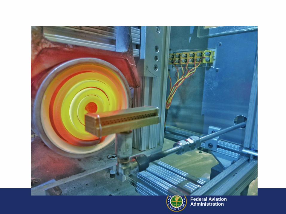
Vertical Flame Propagation Test Apparatus
Federal Aviation Administration
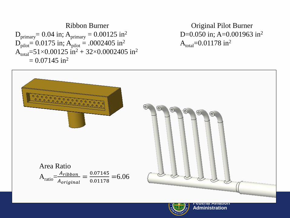
Original Pilot Burner
D=0.050 in; A=0.001963 in2
Atotal=0.01178 in2
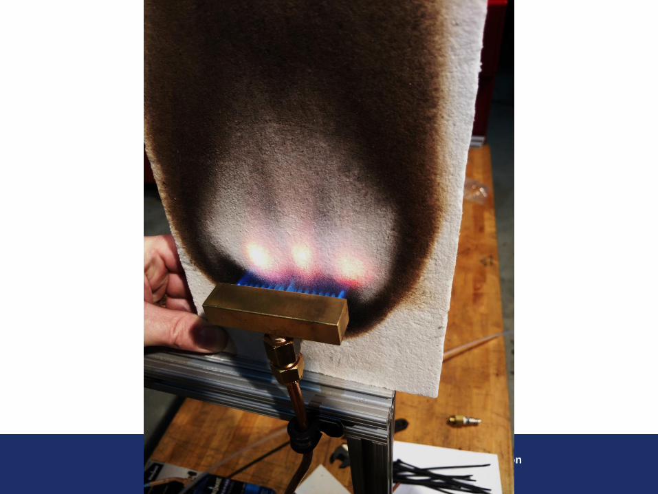
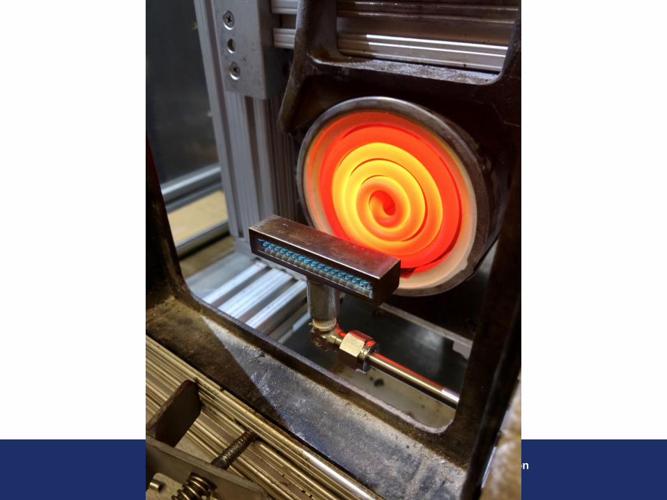
Ribbon Burner
Dprimary= 0.04 in; Aprimary = 0.00125 in2
Dpilot= 0.0175 in; Apilot = .0002405 in2
Atotal=51×0.00125 in2 + 32×0.0002405 in2
= 0.07145 in2
Area Ratio
Aratio=𝐴𝑟𝑖𝑏𝑏𝑜𝑛
𝐴𝑜𝑟𝑖𝑔𝑖𝑛𝑎𝑙=
0.07145
0.01178=6.06
Federal Aviation Administration
Federal Aviation Administration
Federal Aviation Administration
Federal Aviation Administration
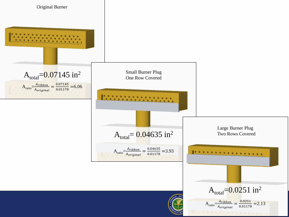
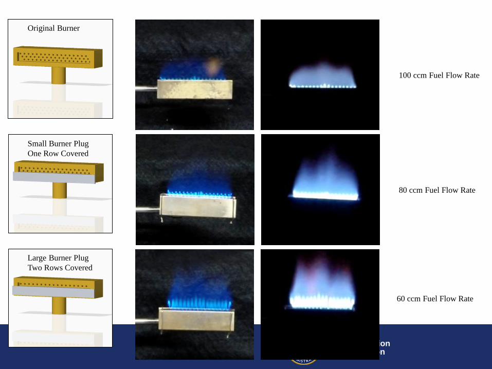
Original Burner
Small Burner Plug
One Row Covered
Large Burner Plug
Two Rows Covered
Atotal=0.0251 in2
Atotal= 0.04635 in2
Atotal=0.07145 in2
Aratio=𝐴𝑟𝑖𝑏𝑏𝑜𝑛
𝐴𝑜𝑟𝑖𝑔𝑖𝑛𝑎𝑙=
0.07145
0.01178=6.06
Aratio=𝐴𝑟𝑖𝑏𝑏𝑜𝑛
𝐴𝑜𝑟𝑖𝑔𝑖𝑛𝑎𝑙=
0.04635
0.01178=3.93
Aratio=𝐴𝑟𝑖𝑏𝑏𝑜𝑛
𝐴𝑜𝑟𝑖𝑔𝑖𝑛𝑎𝑙=
0.0251
0.01178=2.13
Federal Aviation Administration
Federal Aviation Administration
Original Burner
Small Burner Plug
One Row Covered
Large Burner Plug
Two Rows Covered
100 ccm Fuel Flow Rate
80 ccm Fuel Flow Rate
60 ccm Fuel Flow Rate
Federal Aviation Administration
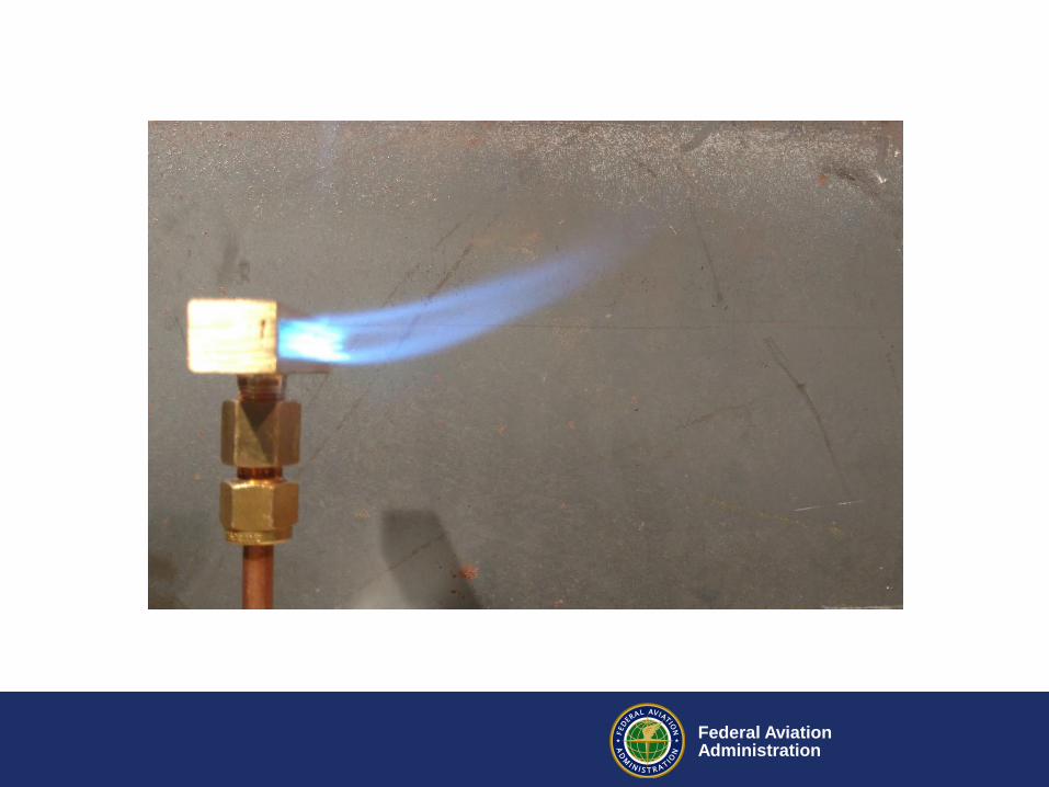
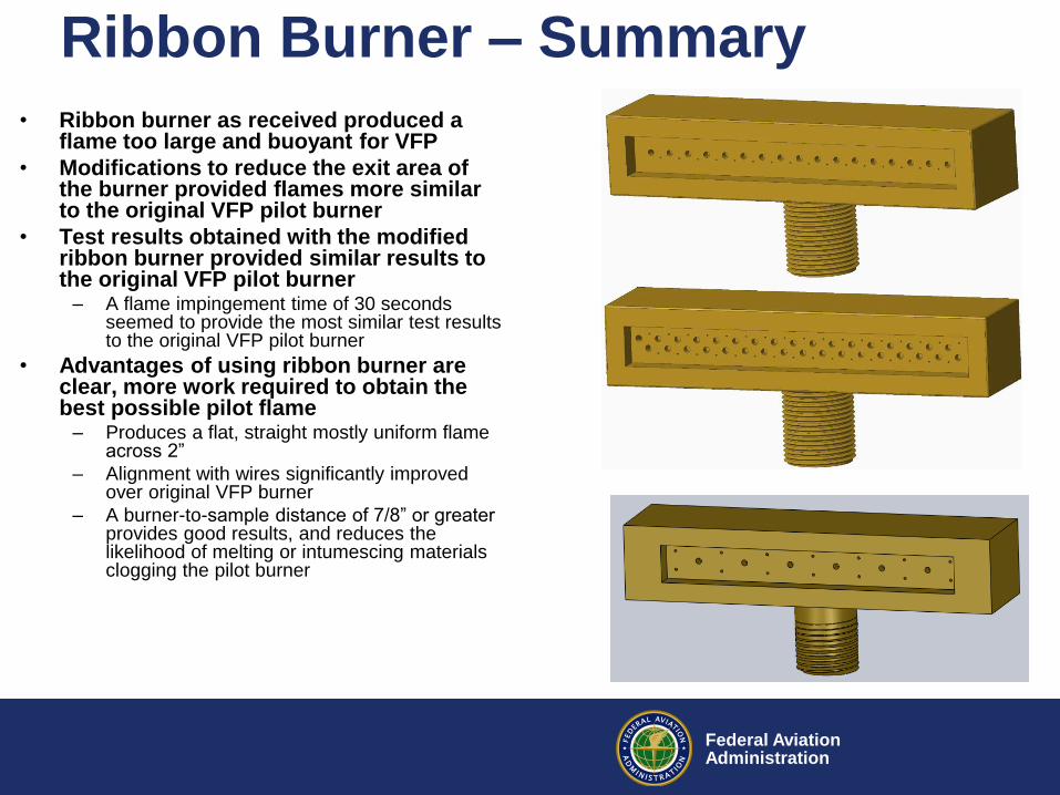
Ribbon Burner – Summary
• Ribbon burner as received produced a flame too large and buoyant for VFP
• Modifications to reduce the exit area of the burner provided flames more similar to the original VFP pilot burner
• Test results obtained with the modified ribbon burner provided similar results to the original VFP pilot burner
– A flame impingement time of 30 seconds seemed to provide the most similar test results to the original VFP pilot burner
• Advantages of using ribbon burner are clear, more work required to obtain the best possible pilot flame
– Produces a flat, straight mostly uniform flame across 2”
– Alignment with wires significantly improved over original VFP burner
– A burner-to-sample distance of 7/8” or greater provides good results, and reduces the likelihood of melting or intumescing materials clogging the pilot burner
Federal Aviation Administration
Ribbon Burner Status
• 3 different burners were ordered in February
• Manufacturer has had significant
production delays
• They are hoping to deliver within the next 2
weeks

Federal Aviation Administration
New Lab – Building 202
• New lab acquired by Fire Safety – VFP was moved in to
B202
• Modifications necessary before testing can begin – Installation of exhaust
hood and piping
– Awaiting approval of design by facility safety and engineering
Federal Aviation Administration
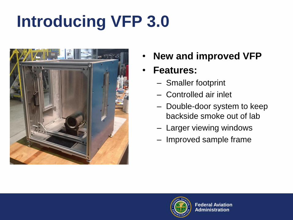
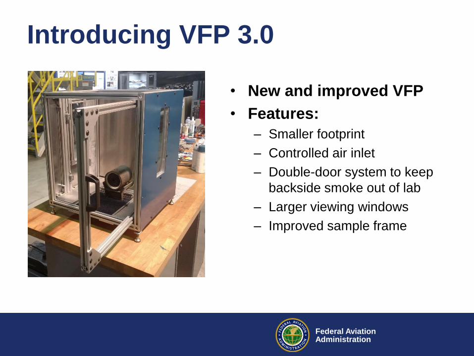
Introducing VFP 3.0
• New and improved VFP
• Features:
– Smaller footprint
– Controlled air inlet
– Double-door system to keep
backside smoke out of lab
– Larger viewing windows
– Improved sample frame
Federal Aviation Administration
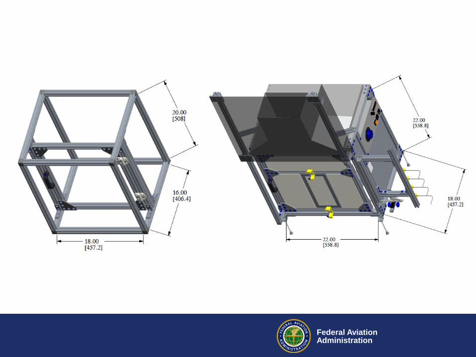
Introducing VFP 3.0
• New and improved VFP
• Features:
– Smaller footprint
– Controlled air inlet
– Double-door system to keep
backside smoke out of lab
– Larger viewing windows
– Improved sample frame
Federal Aviation Administration
Federal Aviation Administration
Contact:
Robert I. Ochs
Fire Safety Branch
William J. Hughes Technical Center
ANG-E212; Bldg 287
Atlantic City, NJ 08405
T 609 485 4651