Embed Size (px)
Citation preview
Pulverised biomass flame propagation and explosion characteristics: problems and solutions.
Prof. Gordon E. Andrews, Energy Research Institute, SCAPE, Univ. Leeds, UK
Pulverised biomass flame propagation and explosion characteristics:
problems and solutions
Professor Gordon E. Andrews
Professor of Combustion Engineering
Energy Research Institute
School of Chemical and Process Engineering (SCAPE)
University of Leeds, LS2 9JT, UK
Co-workers: H.N. Phylaktou, B.M. Gibbs, C.M. Huescar,
A. M. Saeed, D. Slatter, H. Satter.
United Kingdom Explosions Liaison Group, UKELG
University of Leeds, 23.9.14
United Kingdom Explosions Liaison Group, UKELG, meeting on Biomass Dust ExplosionsUniversity of Leeds, 23.9.2014
Pulverised biomass flame propagation and explosion characteristics: problems and solutions.
Prof. Gordon E. Andrews, Energy Research Institute, SCAPE, Univ. Leeds, UK
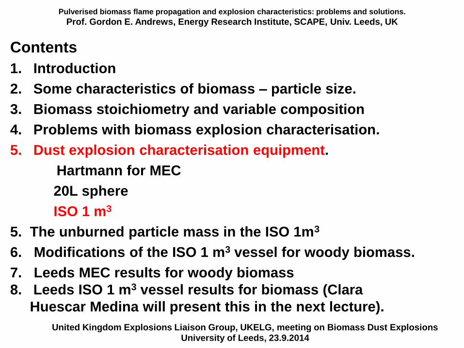
Contents
1. Introduction
2. Some characteristics of biomass – particle size.
3. Biomass stoichiometry and variable composition
4. Problems with biomass explosion characterisation.
5. Dust explosion characterisation equipment.
Hartmann for MEC
20L sphere
ISO 1 m3
5. The unburned particle mass in the ISO 1m3
6. Modifications of the ISO 1 m3 vessel for woody biomass.
7. Leeds MEC results for woody biomass
8. Leeds ISO 1 m3 vessel results for biomass (Clara
Huescar Medina will present this in the next lecture).
United Kingdom Explosions Liaison Group, UKELG, meeting on Biomass Dust ExplosionsUniversity of Leeds, 23.9.2014
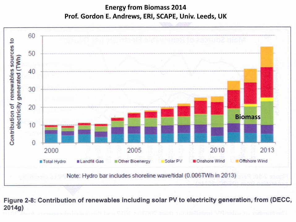
Energy from Biomass 2014Prof. Gordon E. Andrews, ERI, SCAPE, Univ. Leeds, UK
Biomass
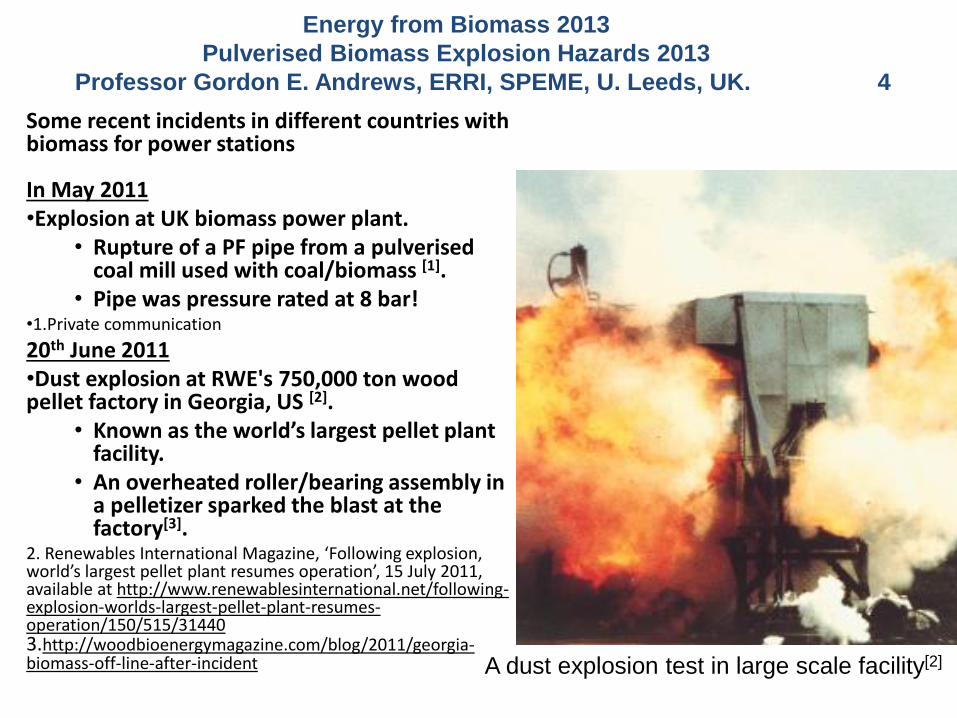
Some recent incidents in different countries with biomass for power stations
In May 2011•Explosion at UK biomass power plant.
• Rupture of a PF pipe from a pulverised coal mill used with coal/biomass [1].
• Pipe was pressure rated at 8 bar!•1.Private communication
20th June 2011•Dust explosion at RWE's 750,000 ton wood pellet factory in Georgia, US [2].
• Known as the world’s largest pellet plant facility.
• An overheated roller/bearing assembly in a pelletizer sparked the blast at the factory[3].
2. Renewables International Magazine, ‘Following explosion, world’s largest pellet plant resumes operation’, 15 July 2011, available at http://www.renewablesinternational.net/following-explosion-worlds-largest-pellet-plant-resumes-operation/150/515/314403.http://woodbioenergymagazine.com/blog/2011/georgia-biomass-off-line-after-incident A dust explosion test in large scale facility[2]
Recent Incidents with Biomass
Dust Explosions
Energy from Biomass 2013
Pulverised Biomass Explosion Hazards 2013
Professor Gordon E. Andrews, ERRI, SPEME, U. Leeds, UK. 4
Pulverised biomass flame propagation and explosion characteristics: problems and solutions.
Prof. Gordon E. Andrews, Energy Research Institute, SCAPE, Univ. Leeds, UK
Contents
1. Introduction
2. Some characteristics of biomass – particle size.
3. Biomass stoichiometry and variable composition
4. Problems with biomass explosion characterisation.
5. Dust explosion characterisation equipment.
Hartmann for MEC
20L sphere
ISO 1 m3
5. The unburned particle mass in the ISO 1m3
6. Modifications of the ISO 1 m3 vessel for woody biomass.
7. Leeds MEC results for woody biomass
8. Leeds ISO 1 m3 vessel results for biomass (Clara
Huescar Medina will present this in the next lecture).
United Kingdom Explosions Liaison Group, UKELG, meeting on Biomass Dust ExplosionsUniversity of Leeds, 23.9.2014
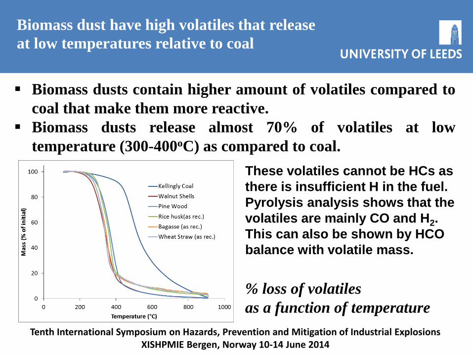
Biomass dusts contain higher amount of volatiles compared to
coal that make them more reactive.
Biomass dusts release almost 70% of volatiles at low
temperature (300-400oC) as compared to coal.
Biomass dust have high volatiles that release
at low temperatures relative to coal
% loss of volatiles
as a function of temperature
Tenth International Symposium on Hazards, Prevention and Mitigation of Industrial ExplosionsXISHPMIE Bergen, Norway 10-14 June 2014
These volatiles cannot be HCs as
there is insufficient H in the fuel.
Pyrolysis analysis shows that the
volatiles are mainly CO and H2.
This can also be shown by HCO
balance with volatile mass.
Pulverised biomass flame propagation and explosion characteristics: problems and solutions.
Prof. Gordon E. Andrews, ERRI, SPEME, U. Leeds 7
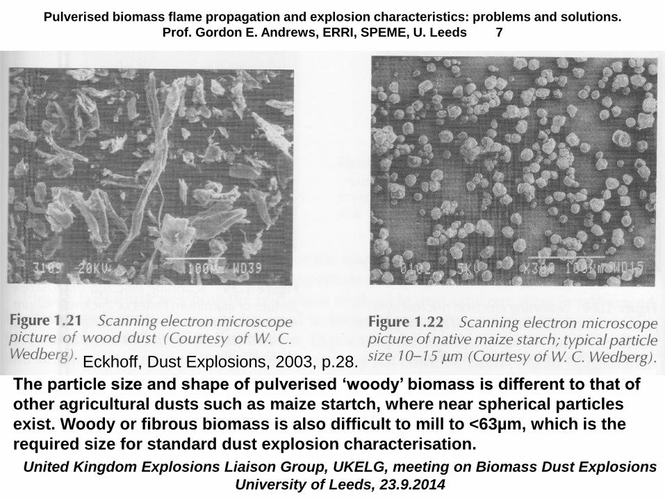
Eckhoff, Dust Explosions, 2003, p.28.
The particle size and shape of pulverised ‘woody’ biomass is different to that of
other agricultural dusts such as maize startch, where near spherical particles
exist. Woody or fibrous biomass is also difficult to mill to <63µm, which is the
required size for standard dust explosion characterisation.
United Kingdom Explosions Liaison Group, UKELG, meeting on Biomass Dust Explosions
University of Leeds, 23.9.2014
Energy from Biomass 2014Prof. Gordon E. Andrews, ERI, SCAPE, Univ. Leeds, UK
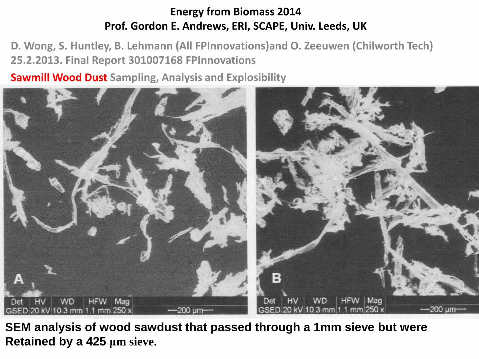
D. Wong, S. Huntley, B. Lehmann (All FPInnovations)and O. Zeeuwen (Chilworth Tech) 25.2.2013. Final Report 301007168 FPInnovations
Sawmill Wood Dust Sampling, Analysis and Explosibility
SEM analysis of wood sawdust that passed through a 1mm sieve but were
Retained by a 425 μm sieve.
Pulverised biomass flame propagation and explosion characteristics: problems and solutions.
Prof. Gordon E. Andrews, Energy Research Institute, SCAPE, Univ. Leeds, UK
United Kingdom Explosions Liaison Group, UKELG, meeting on Biomass Dust ExplosionsUniversity of Leeds, 23.9.2014
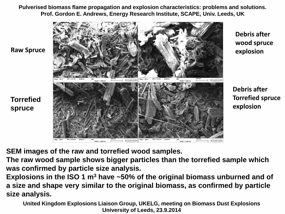
SEM images of the raw and torrefied wood samples.
The raw wood sample shows bigger particles than the torrefied sample which
was confirmed by particle size analysis.
Explosions in the ISO 1 m3 have ~50% of the original biomass unburned and of
a size and shape very similar to the original biomass, as confirmed by particle
size analysis.
Raw Spruce
Torrefied
spruce
Debris afterwood spruceexplosion
Debris afterTorrefied spruceexplosion
Pulverised biomass flame propagation and explosion characteristics: problems and solutions.
Prof. Gordon E. Andrews, Energy Research Institute, SCAPE, Univ. Leeds, UK
The particle size distribution of biomass makes the explosion characterisation more difficult than for gases.
Particle size – pulverised biomass reactivity depends on particle size and I will show evidence from our work and the literature that very coarse biomass particles will explode to up to 500µm.
The results I will show come from work we have done using the Hartmann explosion tube for biomass dusts that show large particles will explode.
Examples of biomass sent to us from power stations show that it is large particles that are being burned and the requirement in dust explosion standards to mill below 63 µm is unrealistic as biomass is not being burned and not exploding in this size range. Typically <2% of the biomass in power stations is <63µm.
However, for regulation compliance you have to mill the biomass into this size range and this is a major problem for the Kg quantities required for the 1 m3 equipment, but easier for the 1g quantities required for the Hartmann explosion tube,
United Kingdom Explosions Liaison Group, UKELG, meeting on Biomass Dust ExplosionsUniversity of Leeds, 23.9.2014

PEME3521 Gas and Dust Explosion Protection 2010Prof. Gordon E. Andrews, ERRI, SPEME, U. Leeds 11
Hartmann, I., Dust explosions in coal
Mining and industry.
The Scientific Monthly, Vol.79,
pp.97-108, 1954
Cornstarch MEC depends
on particle size down to
80-90μm and is then
independent of size.
Minimum ignition energy
continues to decrease as the
size is reduced.
Tenth International Symposium on Hazards, Prevention and Mitigation of Industrial ExplosionsXISHPMIE Bergen, Norway 10-14 June 2014
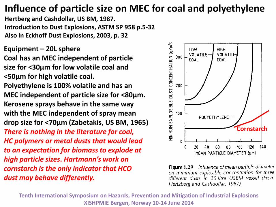
Equipment – 20L sphereCoal has an MEC independent of particlesize for <30µm for low volatile coal and<50µm for high volatile coal.Polyethylene is 100% volatile and has anMEC independent of particle size for <80µm.Kerosene sprays behave in the same waywith the MEC independent of spray meandrop size for <70µm (Zabetakis, US BM, 1965)There is nothing in the literature for coal,HC polymers or metal dusts that would leadto an expectation for biomass to explode athigh particle sizes. Hartmann’s work on cornstarch is the only indicator that HCOdust may behave differently.
Cornstarch
Influence of particle size on MEC for coal and polyethyleneHertberg and Cashdollar, US BM, 1987.Introduction to Dust Explosions, ASTM SP 958 p.5-32Also in Eckhoff Dust Explosions, 2003, p. 32
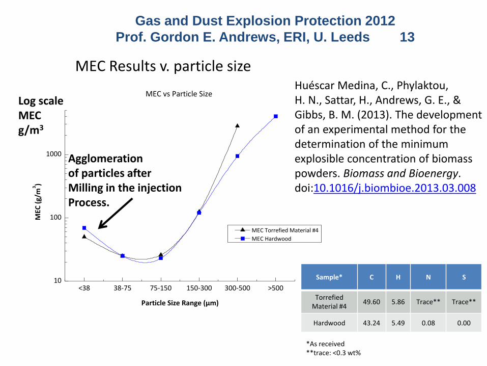
MEC Results v. particle size
Sample* C H N S
Torrefied Material #4
49.60 5.86 Trace** Trace**
Hardwood 43.24 5.49 0.08 0.00
*As received**trace: <0.3 wt%
<38 38-75 75-150 150-300 300-500 >50010
100
1000
MEC
(g/
m3)
Particle Size Range (µm)
MEC Torrefied Material #4
MEC Hardwood
MEC vs Particle Size
Gas and Dust Explosion Protection 2012
Prof. Gordon E. Andrews, ERI, U. Leeds 13
Huéscar Medina, C., Phylaktou, H. N., Sattar, H., Andrews, G. E., & Gibbs, B. M. (2013). The development of an experimental method for the determination of the minimum explosible concentration of biomass powders. Biomass and Bioenergy. doi:10.1016/j.biombioe.2013.03.008
Agglomerationof particles afterMilling in the injectionProcess.
Log scaleMECg/m3
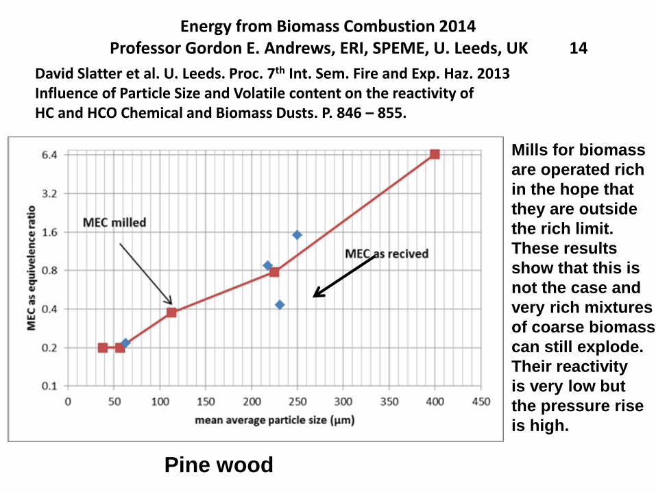
Energy from Biomass Combustion 2014Professor Gordon E. Andrews, ERI, SPEME, U. Leeds, UK 14
David Slatter et al. U. Leeds. Proc. 7th Int. Sem. Fire and Exp. Haz. 2013Influence of Particle Size and Volatile content on the reactivity ofHC and HCO Chemical and Biomass Dusts. P. 846 – 855.
Pine wood
Mills for biomass
are operated rich
in the hope that
they are outside
the rich limit.
These results
show that this is
not the case and
very rich mixtures
of coarse biomass
can still explode.
Their reactivity
is very low but
the pressure rise
is high.
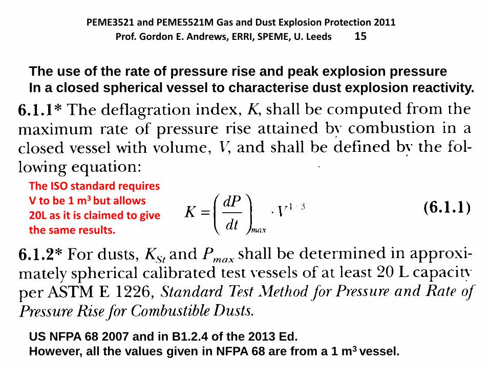
PEME3521 and PEME5521M Gas and Dust Explosion Protection 2011
Prof. Gordon E. Andrews, ERRI, SPEME, U. Leeds 15
US NFPA 68 2007 and in B1.2.4 of the 2013 Ed.
However, all the values given in NFPA 68 are from a 1 m3 vessel.
The use of the rate of pressure rise and peak explosion pressure
In a closed spherical vessel to characterise dust explosion reactivity.
The ISO standard requiresV to be 1 m3 but allows20L as it is claimed to givethe same results.
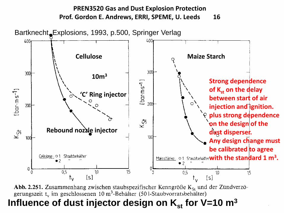
PREN3520 Gas and Dust Explosion ProtectionProf. Gordon E. Andrews, ERRI, SPEME, U. Leeds 16
Bartknecht, Explosions, 1993, p.500, Springer Verlag
Influence of dust injector design on Kst for V=10 m3
Cellulose Maize Starch
‘C’ Ring injector
Rebound nozzle injector
Strong dependenceof Kst on the delaybetween start of airinjection and ignition.plus strong dependenceon the design of thedust disperser.Any design change mustbe calibrated to agreewith the standard 1 m3.
10m3
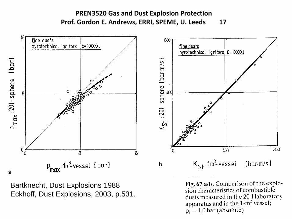
PREN3520 Gas and Dust Explosion ProtectionProf. Gordon E. Andrews, ERRI, SPEME, U. Leeds 17
Bartknecht, Dust Explosions 1988
Eckhoff, Dust Explosions, 2003, p.531.
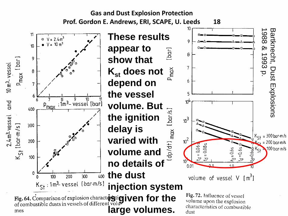
Gas and Dust Explosion ProtectionProf. Gordon E. Andrews, ERI, SCAPE, U. Leeds 18
These results
appear to
show that
Kst does not
depend on
the vessel
volume. But
the ignition
delay is
varied with
volume and
no details of
the dust
injection system
is given for the
large volumes.
Bartk
necht, D
ust E
xplo
sio
ns
1988 &
1993 p
.
Pulverised biomass flame propagation and explosion characteristics: problems and solutions.
Prof. Gordon E. Andrews, Energy Research Institute, SCAPE, Univ. Leeds, UK
I will describe the standard 1 m3 dust explosion vessel is detail later. However,
the value of Kst is strongly dependent on the ignition delay and any value can be
achieved by changing the ignition delay.
The ignition delay controls the turbulence in the vessel following the injection of
the compressed air and hence controls the turbulent acceleration of the flame.
If experiments are carried out in other spherical volumes then the same dust
injection system with the same turbulence levels should be used. Although the
preceeding slide appears to demonstrate this, this is a false demonstration as
the ignition delay in the other volumes is altered to force agreement and the
injection system are not simply scaled from one volume to the next.
I believe data on the 20L sphere, which is legal, is not comparable.
The volume scale up 20L to 1 m3 is a factor of 50 and yet the ignition delay for the
same results is changed by a factor of 10. At larger volume there was not change
in the ignition delay – this apparent agreement is a fudge!
The mass of air used is scaled by a factor of 50 for the same injection pressure
and the hole size should be proportionately scaled for the same turbulence. It
has not been demonstrated that this has been done.
The reason is that the 20L sphere is not scaled from the 1 m3. It has different
injection system, different relative size of the external pot etc.
United Kingdom Explosions Liaison Group, UKELG, meeting on Biomass Dust ExplosionsUniversity of Leeds, 23.9.2014
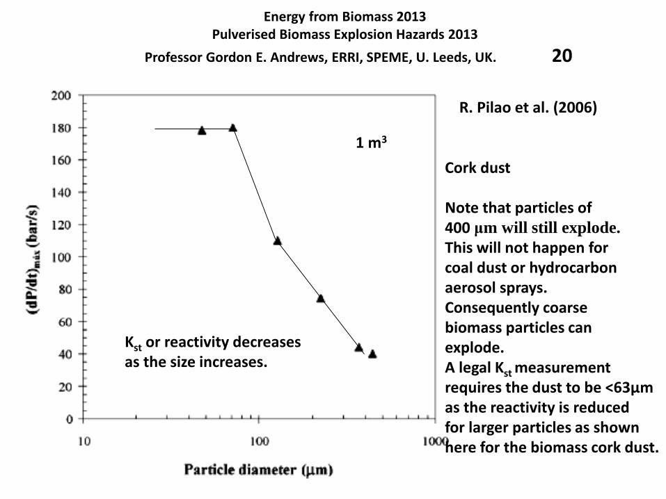
Energy from Biomass 2013Pulverised Biomass Explosion Hazards 2013
Professor Gordon E. Andrews, ERRI, SPEME, U. Leeds, UK. 20
R. Pilao et al. (2006)
Cork dust
Note that particles of 400 μm will still explode.
This will not happen forcoal dust or hydrocarbonaerosol sprays.Consequently coarsebiomass particles canexplode.A legal Kst measurementrequires the dust to be <63µmas the reactivity is reducedfor larger particles as shownhere for the biomass cork dust.
Kst or reactivity decreasesas the size increases.
1 m3
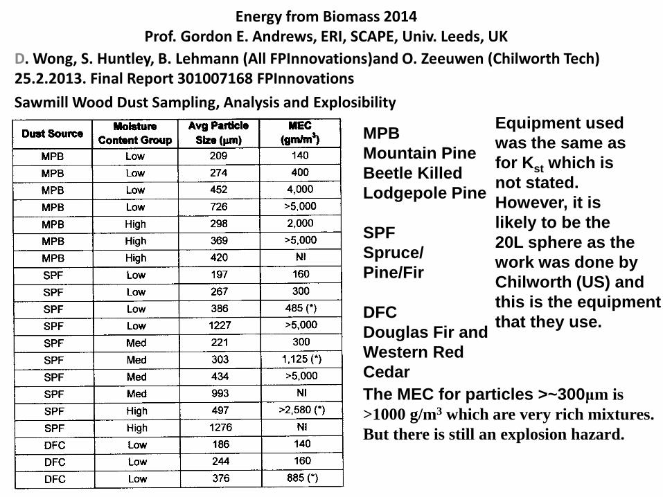
Energy from Biomass 2014Prof. Gordon E. Andrews, ERI, SCAPE, Univ. Leeds, UK
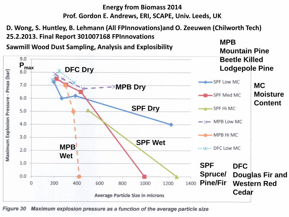
D. Wong, S. Huntley, B. Lehmann (All FPInnovations)and O. Zeeuwen (Chilworth Tech) 25.2.2013. Final Report 301007168 FPInnovations
Sawmill Wood Dust Sampling, Analysis and Explosibility
MPB
Mountain Pine
Beetle Killed
Lodgepole Pine
SPF
Spruce/
Pine/Fir
DFC
Douglas Fir and
Western Red
Cedar
The MEC for particles >~300μm is
>1000 g/m3 which are very rich mixtures.
But there is still an explosion hazard.
Equipment used
was the same as
for Kst which is
not stated.
However, it is
likely to be the
20L sphere as the
work was done by
Chilworth (US) and
this is the equipment
that they use.
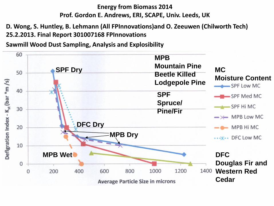
Energy from Biomass 2014Prof. Gordon E. Andrews, ERI, SCAPE, Univ. Leeds, UK
D. Wong, S. Huntley, B. Lehmann (All FPInnovations)and O. Zeeuwen (Chilworth Tech) 25.2.2013. Final Report 301007168 FPInnovations
Sawmill Wood Dust Sampling, Analysis and Explosibility
MC
Moisture
Content
MPB
Mountain Pine
Beetle Killed
Lodgepole Pine
SPF
Spruce/
Pine/Fir
DFC
Douglas Fir and
Western Red
Cedar
MPB Dry
SPF Dry
DFC Dry
MPB
Wet
Pmax
SPF Wet
Energy from Biomass 2014Prof. Gordon E. Andrews, ERI, SCAPE, Univ. Leeds, UK
D. Wong, S. Huntley, B. Lehmann (All FPInnovations)and O. Zeeuwen (Chilworth Tech) 25.2.2013. Final Report 301007168 FPInnovations
Sawmill Wood Dust Sampling, Analysis and Explosibility
MC
Moisture Content
MPB
Mountain Pine
Beetle Killed
Lodgepole Pine
SPF
Spruce/
Pine/Fir
DFC
Douglas Fir and
Western Red
Cedar
SPF Dry
DFC Dry
MPB Dry
MPB Wet

Pulverised biomass flame propagation and explosion characteristics: problems and solutions.
Prof. Gordon E. Andrews, Energy Research Institute, SCAPE, Univ. Leeds, UK
Contents
1. Introduction
2. Some characteristics of biomass – particle size.
3. Biomass stoichiometry and variable composition
4. Problems with biomass explosion characterisation.
5. Dust explosion characterisation equipment.
Hartmann for MEC
20L sphere
ISO 1 m3
5. The unburned particle mass in the ISO 1m3
6. Modifications of the ISO 1 m3 vessel for woody biomass.
7. Leeds MEC results for woody biomass
8. Leeds ISO 1 m3 vessel results for biomass (Clara
Huescar Medina will present this in the next lecture).
United Kingdom Explosions Liaison Group, UKELG, meeting on Biomass Dust ExplosionsUniversity of Leeds, 23.9.2014
Pulverised biomass flame propagation and explosion characteristics: problems and solutions.
Prof. Gordon E. Andrews, Energy Research Institute, SCAPE, Univ. Leeds, UK
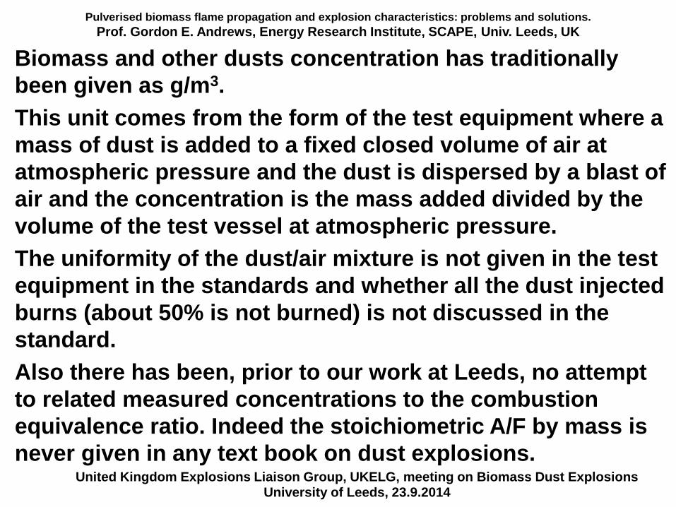
Biomass and other dusts concentration has traditionally
been given as g/m3.
This unit comes from the form of the test equipment where a
mass of dust is added to a fixed closed volume of air at
atmospheric pressure and the dust is dispersed by a blast of
air and the concentration is the mass added divided by the
volume of the test vessel at atmospheric pressure.
The uniformity of the dust/air mixture is not given in the test
equipment in the standards and whether all the dust injected
burns (about 50% is not burned) is not discussed in the
standard.
Also there has been, prior to our work at Leeds, no attempt
to related measured concentrations to the combustion
equivalence ratio. Indeed the stoichiometric A/F by mass is
never given in any text book on dust explosions.United Kingdom Explosions Liaison Group, UKELG, meeting on Biomass Dust Explosions
University of Leeds, 23.9.2014
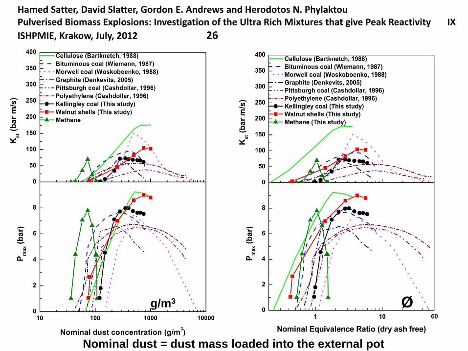
Hamed Satter, David Slatter, Gordon E. Andrews and Herodotos N. PhylaktouPulverised Biomass Explosions: Investigation of the Ultra Rich Mixtures that give Peak Reactivity IX
ISHPMIE, Krakow, July, 2012 26
Nominal dust = dust mass loaded into the external pot
g/m3 Ø
Pulverised biomass flame propagation and explosion characteristics: problems and solutions.
Prof. Gordon E. Andrews, Energy Research Institute, SCAPE, Univ. Leeds, UK
A consequence of the small variability in composition of
hydrocarbon fuels is that gas composition variability is
rarely investigated in gas explosion work.
Most explosion data is for natural gas or LPG fuels and
sometimes the pure fuels methane and propane are used.
This is of current concern with the addition of biomethane
to the gas grid, but even then the variability will be small
relative to that for biomass.
One of the explosion protection measures is ventilation
with a requirement to operate at 25% of the lean
flammability limit or minimum explosions concentration for
dusts. For HCs this can be set at a fixed ventilation rate and
the composition of gas or vapour largely ignored as the
lean limits are similar, as will be shown.
This is NOT the case for biomass.United Kingdom Explosions Liaison Group, UKELG, meeting on Biomass Dust Explosions
University of Leeds, 23.9.2014
Pulverised biomass flame propagation and explosion characteristics: problems and solutions.
Prof. Gordon E. Andrews, Energy Research Institute, SCAPE, Univ. Leeds, UK
To determine the stoichiometric A/F by mass of a fuel we only need to know the H/C for hydrocarbons
and H/C and O/C for biomass fuels.
The N and S content is usually too low to be significant in affecting the A/F by mass.
Gas fuels do not have ash or water content whereas biomass fuels do – this adds to the variability in the stoichiometric A/F by mass.
Knowing where you are relative to stoichiometric and carrying out explosion protection for the worst case explosion equivalence ratio (~Ø = 1.05) is fundamental to gas explosion research. For dust explosions their explosion behaviour is quite different to gases in terms of the dependence on mixture fraction or Ø and this has rarely been commented on in the literature.
United Kingdom Explosions Liaison Group, UKELG, meeting on Biomass Dust ExplosionsUniversity of Leeds, 23.9.2014
Pulverised biomass flame propagation and explosion characteristics: problems and solutions.
Prof. Gordon E. Andrews, Energy Research Institute, SCAPE, Univ. Leeds, UK
United Kingdom Explosions Liaison Group, UKELG, meeting on Biomass Dust ExplosionsUniversity of Leeds, 23.9.2014
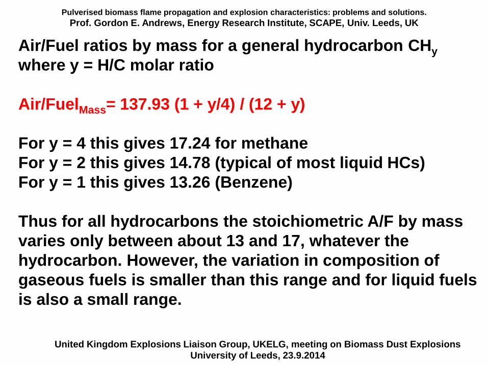
Air/Fuel ratios by mass for a general hydrocarbon CHy
where y = H/C molar ratio
Air/FuelMass= 137.93 (1 + y/4) / (12 + y)
For y = 4 this gives 17.24 for methane
For y = 2 this gives 14.78 (typical of most liquid HCs)
For y = 1 this gives 13.26 (Benzene)
Thus for all hydrocarbons the stoichiometric A/F by mass
varies only between about 13 and 17, whatever the
hydrocarbon. However, the variation in composition of
gaseous fuels is smaller than this range and for liquid fuels
is also a small range.
Biomass Combustion and Emissions
Prof. Gordon E. Andrews, Energy Research Institute, SCAPE, Univ. Leeds, UK
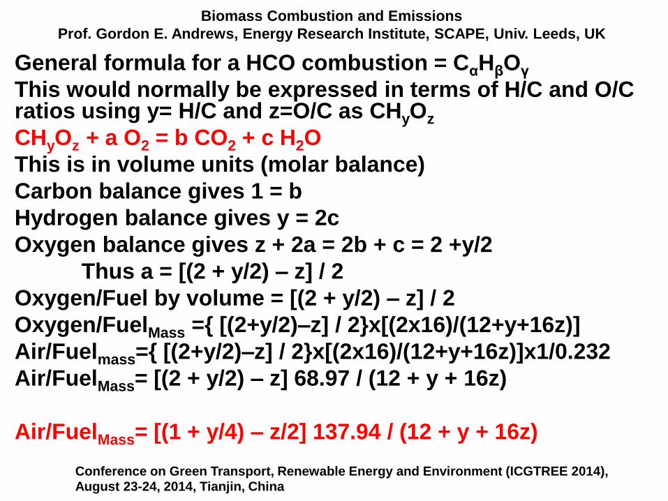
General formula for a HCO combustion = CαHβOγ
This would normally be expressed in terms of H/C and O/C ratios using y= H/C and z=O/C as CHyOz
CHyOz + a O2 = b CO2 + c H2O
This is in volume units (molar balance)
Carbon balance gives 1 = b
Hydrogen balance gives y = 2c
Oxygen balance gives z + 2a = 2b + c = 2 +y/2
Thus a = [(2 + y/2) – z] / 2
Oxygen/Fuel by volume = [(2 + y/2) – z] / 2
Oxygen/FuelMass ={ [(2+y/2)–z] / 2}x[(2x16)/(12+y+16z)]
Air/Fuelmass={ [(2+y/2)–z] / 2}x[(2x16)/(12+y+16z)]x1/0.232
Air/FuelMass= [(2 + y/2) – z] 68.97 / (12 + y + 16z)
Air/FuelMass= [(1 + y/4) – z/2] 137.94 / (12 + y + 16z)
Conference on Green Transport, Renewable Energy and Environment (ICGTREE 2014), August 23-24, 2014, Tianjin, China
Pulverised biomass flame propagation and explosion characteristics: problems and solutions.
Prof. Gordon E. Andrews, Energy Research Institute, SCAPE, Univ. Leeds, UK
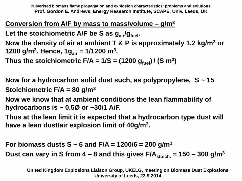
Conversion from A/F by mass to mass/volume – g/m3
Let the stoichiometric A/F be S as gair/gfuel.
Now the density of air at ambient T & P is approximately 1.2 kg/m3 or
1200 g/m3. Hence, 1gair = 1/1200 m3.
Thus the stoichiometric F/A = 1/S = (1200 gfuel) / (S m3)
Now for a hydrocarbon solid dust such, as polypropylene, S ~ 15
Stoichiometric F/A = 80 g/m3
Now we know that at ambient conditions the lean flammability of
hydrocarbons is ~ 0.5Ø or ~30/1 A/F.
Thus at the lean limit it is expected that a hydrocarbon type dust will
have a lean dust/air explosion limit of 40g/m3.
For biomass dusts S ~ 6 and F/A = 1200/6 = 200 g/m3
Dust can vary in S from 4 – 8 and this gives F/Astoich. = 150 – 300 g/m3
United Kingdom Explosions Liaison Group, UKELG, meeting on Biomass Dust ExplosionsUniversity of Leeds, 23.9.2014
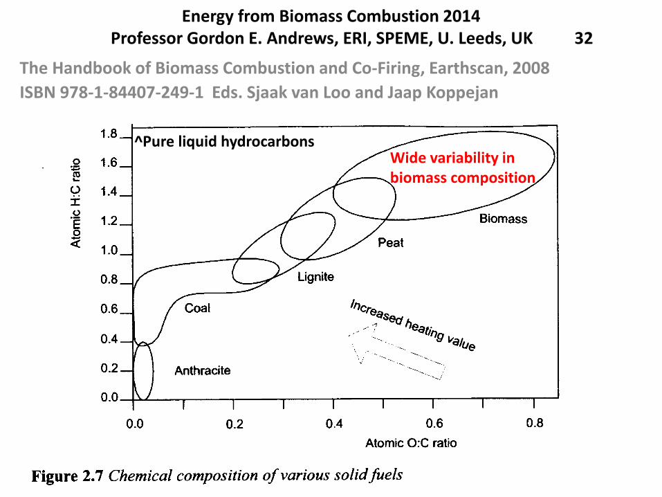
Energy from Biomass Combustion 2014Professor Gordon E. Andrews, ERI, SPEME, U. Leeds, UK 32
The Handbook of Biomass Combustion and Co-Firing, Earthscan, 2008
ISBN 978-1-84407-249-1 Eds. Sjaak van Loo and Jaap Koppejan
^Pure liquid hydrocarbonsWide variability in biomass composition
Pulverised biomass flame propagation and explosion characteristics: problems and solutions.
Prof. Gordon E. Andrews, Energy Research Institute, SCAPE, Univ. Leeds, UK
United Kingdom Explosions Liaison Group, UKELG, meeting on Biomass Dust ExplosionsUniversity of Leeds, 23.9.2014
0.0
0.5
1.0
1.5
2.0
2.5
3.0
0.0 0.2 0.4 0.6 0.8 1.0
H/C
O/C
Wood and woody biomass
Animal biomass
Contaminated biomass
Biomass residues
Straws
Grasses
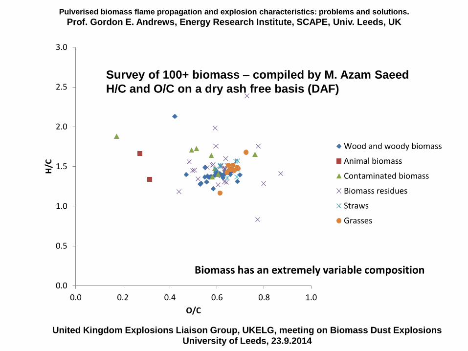
Survey of 100+ biomass – compiled by M. Azam Saeed
H/C and O/C on a dry ash free basis (DAF)
Biomass has an extremely variable composition
Pulverised biomass flame propagation and explosion characteristics: problems and solutions.
Prof. Gordon E. Andrews, Energy Research Institute, SCAPE, Univ. Leeds, UK
United Kingdom Explosions Liaison Group, UKELG, meeting on Biomass Dust ExplosionsUniversity of Leeds, 23.9.2014
0
5000
10000
15000
20000
25000
0 2 4 6 8 10 12 14
CV
(kJ
/kg)
Stoich. A/F 'g/g'
Wood and woody biomass
Animal biomass
Contaminated biomass
Biomass residue
Straws
Grasses
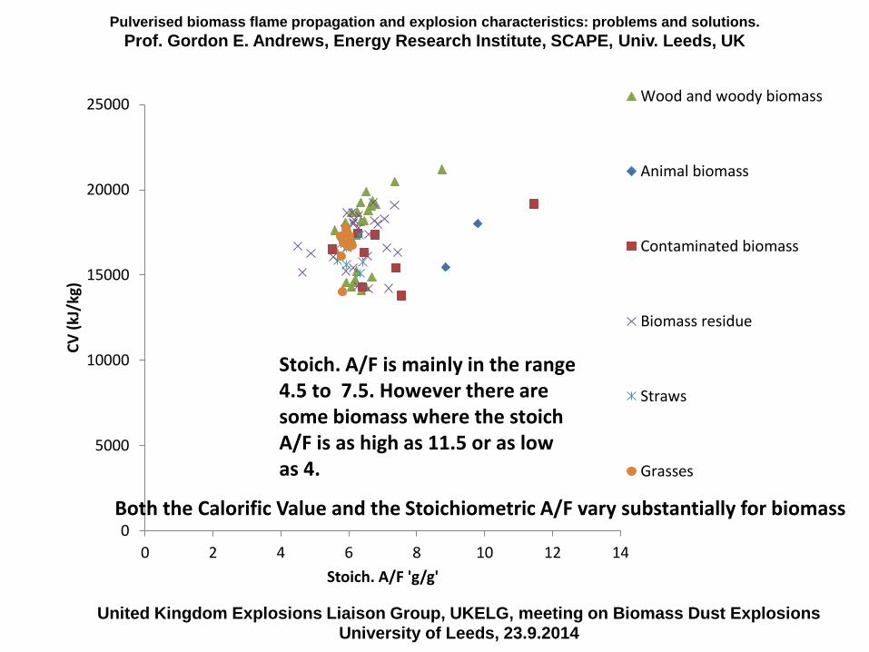
Stoich. A/F is mainly in the range 4.5 to 7.5. However there are some biomass where the stoichA/F is as high as 11.5 or as low as 4.
Both the Calorific Value and the Stoichiometric A/F vary substantially for biomass
Stoichiometry, passive fire protection and air supply, fire load, estimation of fire heat release rate.
Prof. Gordon E. Andrews, ERI, SPEME, U. Leeds, UK 35
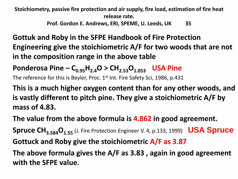
Gottuk and Roby in the SFPE Handbook of Fire Protection Engineering give the stoichiometric A/F for two woods that are not in the composition range in the above table
Ponderosa Pine – C0.95H2.4O > CH2.53O1.053 USA PineThe reference for this is Beyler, Proc. 1st Int. Fire Safety Sci, 1986, p.431
This is a much higher oxygen content than for any other woods, and is vastly different to pitch pine. They give a stoichiometric A/F by mass of 4.83.
The value from the above formula is 4.862 in good agreement.
Spruce CH3.584O1.55 (J. Fire Protection Engineer V. 4, p.133, 1999) USA Spruce
Gottuck and Roby give the stoichiometric A/F as 3.87
The above formula gives the A/F as 3.83 , again in good agreement with the SFPE value.
Pulverised biomass flame propagation and explosion characteristics: problems and solutions.
Prof. Gordon E. Andrews, Energy Research Institute, SCAPE, Univ. Leeds, UK
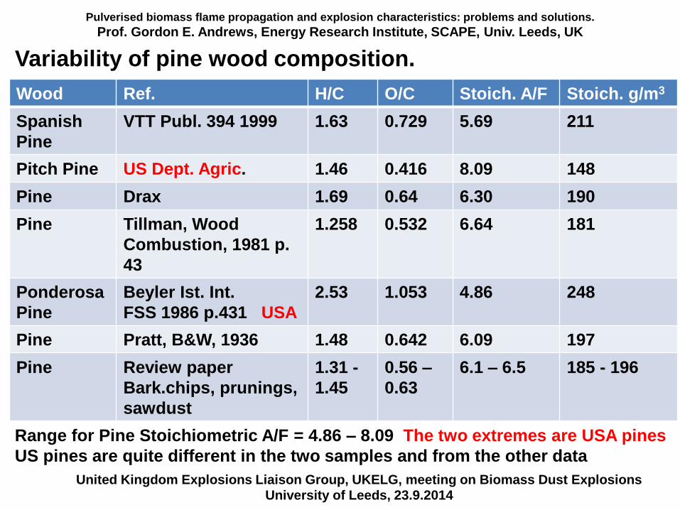
Variability of pine wood composition.
United Kingdom Explosions Liaison Group, UKELG, meeting on Biomass Dust ExplosionsUniversity of Leeds, 23.9.2014
Wood Ref. H/C O/C Stoich. A/F Stoich. g/m3
Spanish
Pine
VTT Publ. 394 1999 1.63 0.729 5.69 211
Pitch Pine US Dept. Agric. 1.46 0.416 8.09 148
Pine Drax 1.69 0.64 6.30 190
Pine Tillman, Wood
Combustion, 1981 p.
43
1.258 0.532 6.64 181
Ponderosa
Pine
Beyler Ist. Int.
FSS 1986 p.431 USA
2.53 1.053 4.86 248
Pine Pratt, B&W, 1936 1.48 0.642 6.09 197
Pine Review paper
Bark.chips, prunings,
sawdust
1.31 -
1.45
0.56 –
0.63
6.1 – 6.5 185 - 196
Range for Pine Stoichiometric A/F = 4.86 – 8.09 The two extremes are USA pines
US pines are quite different in the two samples and from the other data
Pulverised biomass flame propagation and explosion characteristics: problems and solutions.
Prof. Gordon E. Andrews, Energy Research Institute, SCAPE, Univ. Leeds, UK
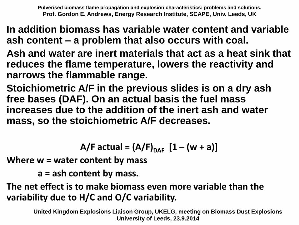
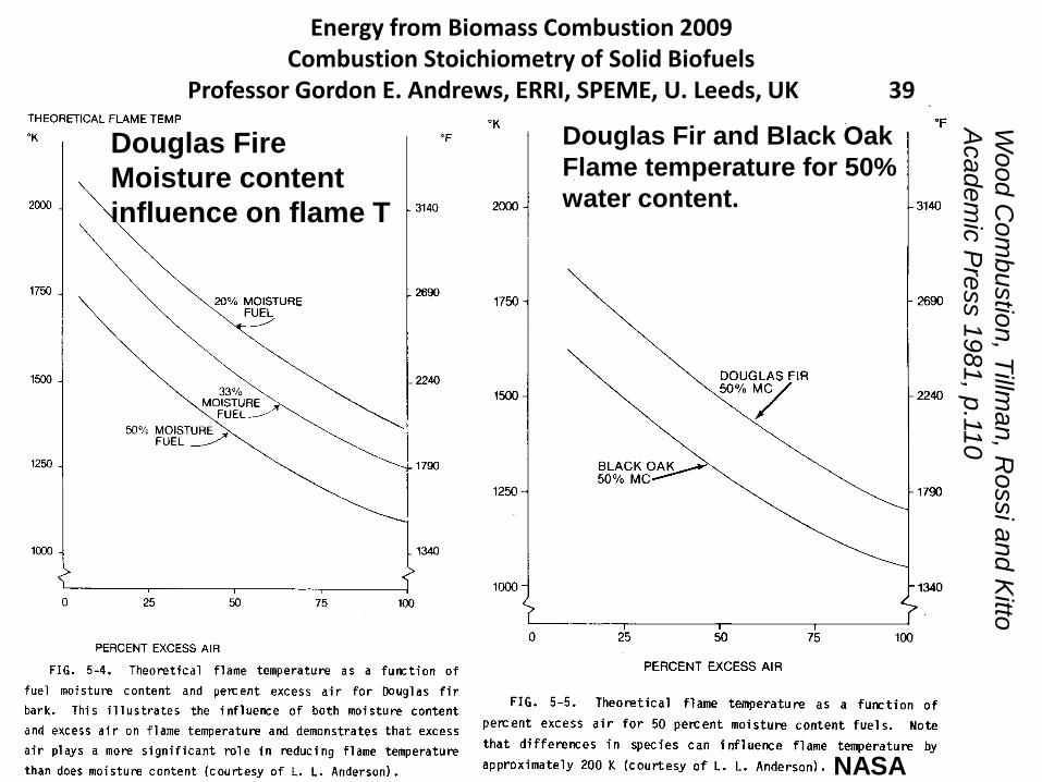
In addition biomass has variable water content and variable ash content – a problem that also occurs with coal.
Ash and water are inert materials that act as a heat sink that reduces the flame temperature, lowers the reactivity and narrows the flammable range.
Stoichiometric A/F in the previous slides is on a dry ash free bases (DAF). On an actual basis the fuel mass increases due to the addition of the inert ash and water mass, so the stoichiometric A/F decreases.
A/F actual = (A/F)DAF [1 – (w + a)]
Where w = water content by mass
a = ash content by mass.
The net effect is to make biomass even more variable than the variability due to H/C and O/C variability.
United Kingdom Explosions Liaison Group, UKELG, meeting on Biomass Dust ExplosionsUniversity of Leeds, 23.9.2014
Energy from Biomass Combustion 2011Combustion Stoichiometry of Solid Biofuels
Professor Gordon E. Andrews, ERI, SPEME, U. Leeds, UK 38
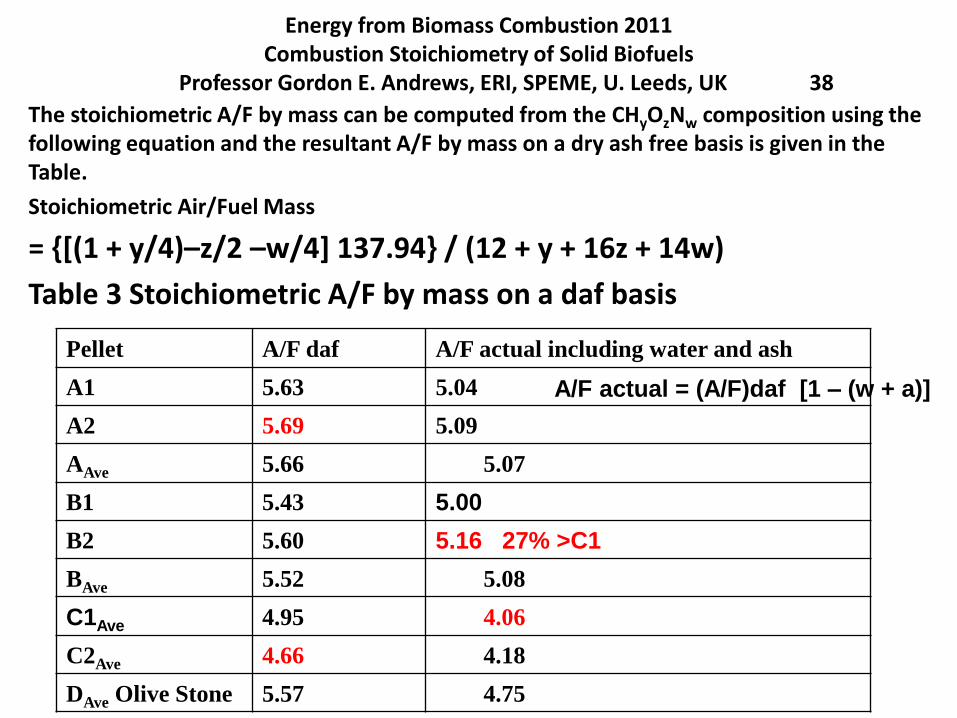
The stoichiometric A/F by mass can be computed from the CHyOzNw composition using the following equation and the resultant A/F by mass on a dry ash free basis is given in the Table.
Stoichiometric Air/Fuel Mass
= {[(1 + y/4)–z/2 –w/4] 137.94} / (12 + y + 16z + 14w)
Table 3 Stoichiometric A/F by mass on a daf basis
Pellet A/F daf A/F actual including water and ash
A1 5.63 5.04
A2 5.69 5.09
AAve 5.66 5.07
B1 5.43 5.00
B2 5.60 5.16 27% >C1
BAve 5.52 5.08
C1Ave 4.95 4.06
C2Ave 4.66 4.18
DAve Olive Stone 5.57 4.75
A/F actual = (A/F)daf [1 – (w + a)]
Energy from Biomass Combustion 2009Combustion Stoichiometry of Solid Biofuels
Professor Gordon E. Andrews, ERRI, SPEME, U. Leeds, UK 39
Douglas Fire
Moisture content
influence on flame T
Douglas Fir and Black Oak
Flame temperature for 50%
water content.
NASA
Wood C
om
bustio
n, T
illman, R
ossi a
nd K
itto
Academ
ic P
ress 1
981, p
.110
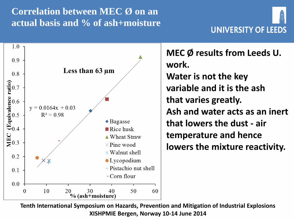
Correlation between MEC Ø on an
actual basis and % of ash+moisture
Tenth International Symposium on Hazards, Prevention and Mitigation of Industrial ExplosionsXISHPMIE Bergen, Norway 10-14 June 2014
MEC Ø results from Leeds U. work.Water is not the keyvariable and it is the ashthat varies greatly.Ash and water acts as an inert that lowers the dust - airtemperature and hencelowers the mixture reactivity.
Pulverised biomass flame propagation and explosion characteristics: problems and solutions.
Prof. Gordon E. Andrews, Energy Research Institute, SCAPE, Univ. Leeds, UK
United Kingdom Explosions Liaison Group, UKELG, meeting on Biomass Dust ExplosionsUniversity of Leeds, 23.9.2014
0
0,2
0,4
0,6
0,8
1
1,2
1,4
1,6
1,8
0 2 4 6 8 10 12 14 16 18
Min
imu
m e
xp
losi
ble
eq
uiv
ale
nce r
ati
o
Moisture (%)
Raw5
SSD
PWP
TM5
TM6
TM8S
TM8A
TM8B
TM9
WALNUT
DBD
PISTACHIO
WOOD
BARK
FOREST RESIDUE
SPANISH PINE
BARLEY STRAW
MISCANTHUS
SORGHUM
RAPE SEED STRAW
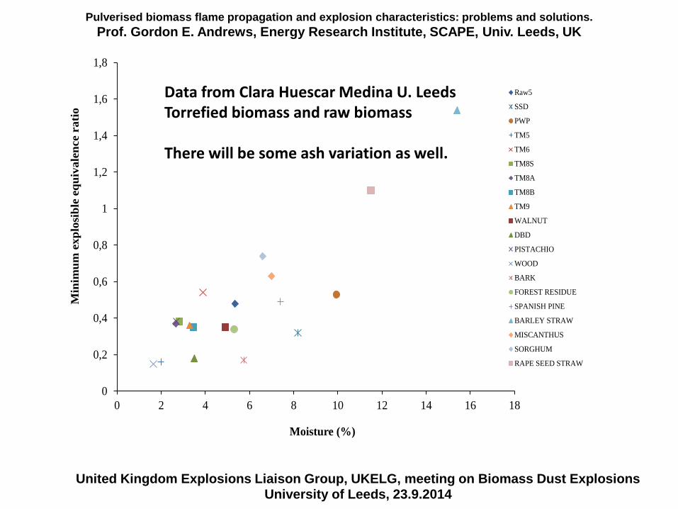
Data from Clara Huescar Medina U. LeedsTorrefied biomass and raw biomass
There will be some ash variation as well.
Pulverised biomass flame propagation and explosion characteristics: problems and solutions.
Prof. Gordon E. Andrews, Energy Research Institute, SCAPE, Univ. Leeds, UK
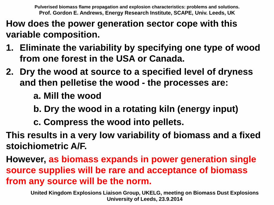
How does the power generation sector cope with this
variable composition.
1. Eliminate the variability by specifying one type of wood
from one forest in the USA or Canada.
2. Dry the wood at source to a specified level of dryness
and then pelletise the wood - the processes are:
a. Mill the wood
b. Dry the wood in a rotating kiln (energy input)
c. Compress the wood into pellets.
This results in a very low variability of biomass and a fixed
stoichiometric A/F.
However, as biomass expands in power generation single
source supplies will be rare and acceptance of biomass
from any source will be the norm.United Kingdom Explosions Liaison Group, UKELG, meeting on Biomass Dust Explosions
University of Leeds, 23.9.2014
Pulverised biomass flame propagation and explosion characteristics: problems and solutions.
Prof. Gordon E. Andrews, Energy Research Institute, SCAPE, Univ. Leeds, UK
Contents
1. Introduction
2. Some characteristics of biomass – particle size.
3. Biomass stoichiometry and variable composition
4. Problems with biomass explosion characterisation.
5. Dust explosion characterisation equipment.
Hartmann for MEC
20L sphere
ISO 1 m3
5. The unburned particle mass in the ISO 1m3
6. Modifications of the ISO 1 m3 vessel for woody biomass.
7. Leeds MEC results for woody biomass
8. Leeds ISO 1 m3 vessel results for biomass (Clara
Huescar Medina will present this in the next lecture).
United Kingdom Explosions Liaison Group, UKELG, meeting on Biomass Dust ExplosionsUniversity of Leeds, 23.9.2014
Pulverised biomass flame propagation and explosion characteristics: problems and solutions.
Prof. Gordon E. Andrews, Energy Research Institute, SCAPE, Univ. Leeds, UK
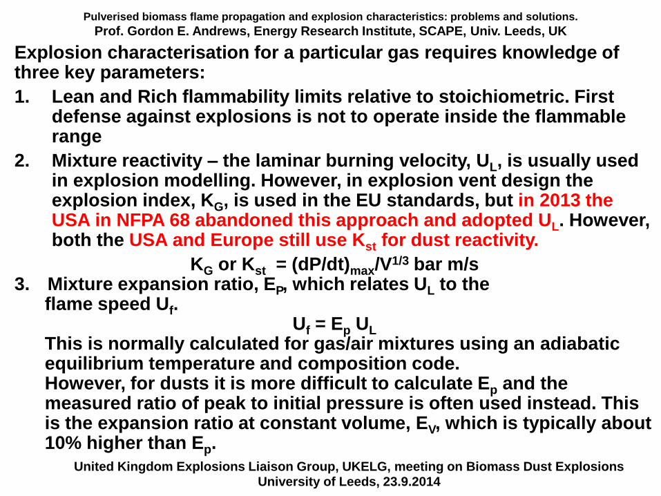
Explosion characterisation for a particular gas requires knowledge of three key parameters:
1. Lean and Rich flammability limits relative to stoichiometric. First defense against explosions is not to operate inside the flammable range
2. Mixture reactivity – the laminar burning velocity, UL, is usually used in explosion modelling. However, in explosion vent design the explosion index, KG, is used in the EU standards, but in 2013 the USA in NFPA 68 abandoned this approach and adopted UL. However, both the USA and Europe still use Kst for dust reactivity.
KG or Kst = (dP/dt)max/V1/3 bar m/s
3. Mixture expansion ratio, EP, which relates UL to the flame speed Uf.
Uf = Ep UL
This is normally calculated for gas/air mixtures using an adiabatic equilibrium temperature and composition code.However, for dusts it is more difficult to calculate Ep and the measured ratio of peak to initial pressure is often used instead. This is the expansion ratio at constant volume, EV, which is typically about10% higher than Ep.
United Kingdom Explosions Liaison Group, UKELG, meeting on Biomass Dust ExplosionsUniversity of Leeds, 23.9.2014
Pulverised biomass flame propagation and explosion characteristics: problems and solutions.
Prof. Gordon E. Andrews, Energy Research Institute, SCAPE, Univ. Leeds, UK
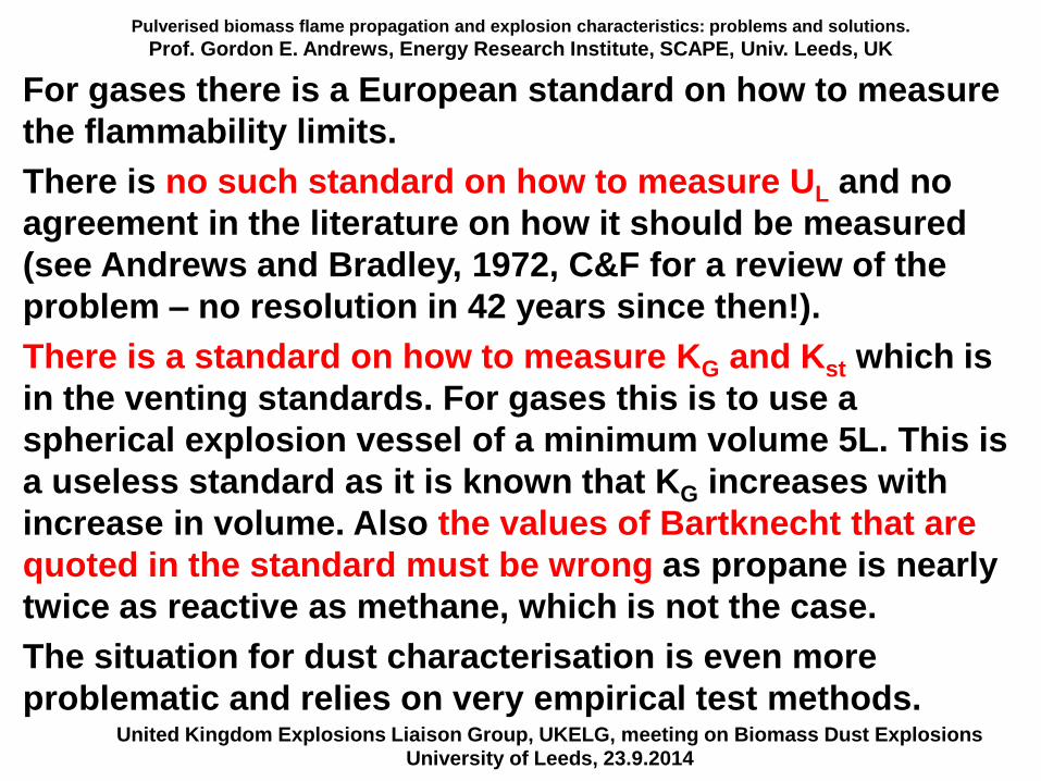
For gases there is a European standard on how to measure
the flammability limits.
There is no such standard on how to measure UL and no
agreement in the literature on how it should be measured
(see Andrews and Bradley, 1972, C&F for a review of the
problem – no resolution in 42 years since then!).
There is a standard on how to measure KG and Kst which is
in the venting standards. For gases this is to use a
spherical explosion vessel of a minimum volume 5L. This is
a useless standard as it is known that KG increases with
increase in volume. Also the values of Bartknecht that are
quoted in the standard must be wrong as propane is nearly
twice as reactive as methane, which is not the case.
The situation for dust characterisation is even more
problematic and relies on very empirical test methods.United Kingdom Explosions Liaison Group, UKELG, meeting on Biomass Dust Explosions
University of Leeds, 23.9.2014
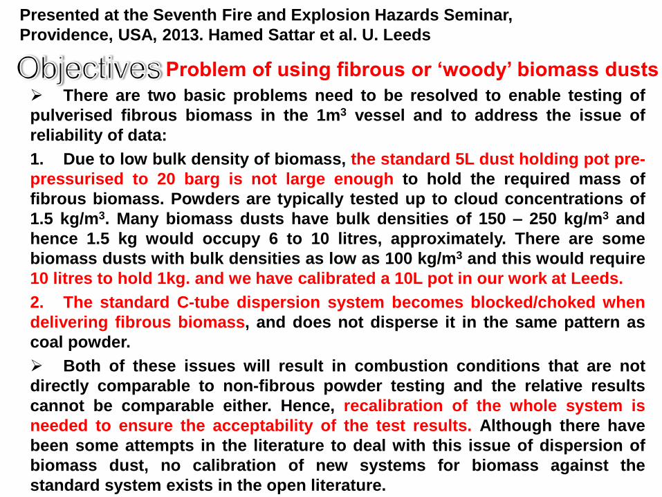
There are two basic problems need to be resolved to enable testing of
pulverised fibrous biomass in the 1m3 vessel and to address the issue of
reliability of data:
1. Due to low bulk density of biomass, the standard 5L dust holding pot pre-
pressurised to 20 barg is not large enough to hold the required mass of
fibrous biomass. Powders are typically tested up to cloud concentrations of
1.5 kg/m3. Many biomass dusts have bulk densities of 150 – 250 kg/m3 and
hence 1.5 kg would occupy 6 to 10 litres, approximately. There are some
biomass dusts with bulk densities as low as 100 kg/m3 and this would require
10 litres to hold 1kg. and we have calibrated a 10L pot in our work at Leeds.
2. The standard C-tube dispersion system becomes blocked/choked when
delivering fibrous biomass, and does not disperse it in the same pattern as
coal powder.
Both of these issues will result in combustion conditions that are not
directly comparable to non-fibrous powder testing and the relative results
cannot be comparable either. Hence, recalibration of the whole system is
needed to ensure the acceptability of the test results. Although there have
been some attempts in the literature to deal with this issue of dispersion of
biomass dust, no calibration of new systems for biomass against the
standard system exists in the open literature.
Presented at the Seventh Fire and Explosion Hazards Seminar,
Providence, USA, 2013. Hamed Sattar et al. U. Leeds
Problem of using fibrous or ‘woody’ biomass dusts
Pulverised biomass flame propagation and explosion characteristics: problems and solutions.
Prof. Gordon E. Andrews, Energy Research Institute, SCAPE, Univ. Leeds, UK
Contents
1. Introduction
2. Some characteristics of biomass – particle size.
3. Biomass stoichiometry and variable composition
4. Problems with biomass explosion characterisation.
5. Dust explosion characterisation equipment.
Hartmann for MEC
20L sphere
ISO 1 m3
5. The unburned particle mass in the ISO 1m3
6. Modifications of the ISO 1 m3 vessel for woody biomass.
7. Leeds MEC results for woody biomass
8. Leeds ISO 1 m3 vessel results for biomass (Clara
Huescar Medina will present this in the next lecture).
United Kingdom Explosions Liaison Group, UKELG, meeting on Biomass Dust ExplosionsUniversity of Leeds, 23.9.2014
PREN3520 Gas and Dust Explosion ProtectionProf. Gordon E. Andrews, ERRI, SPEME, U. Leeds 48
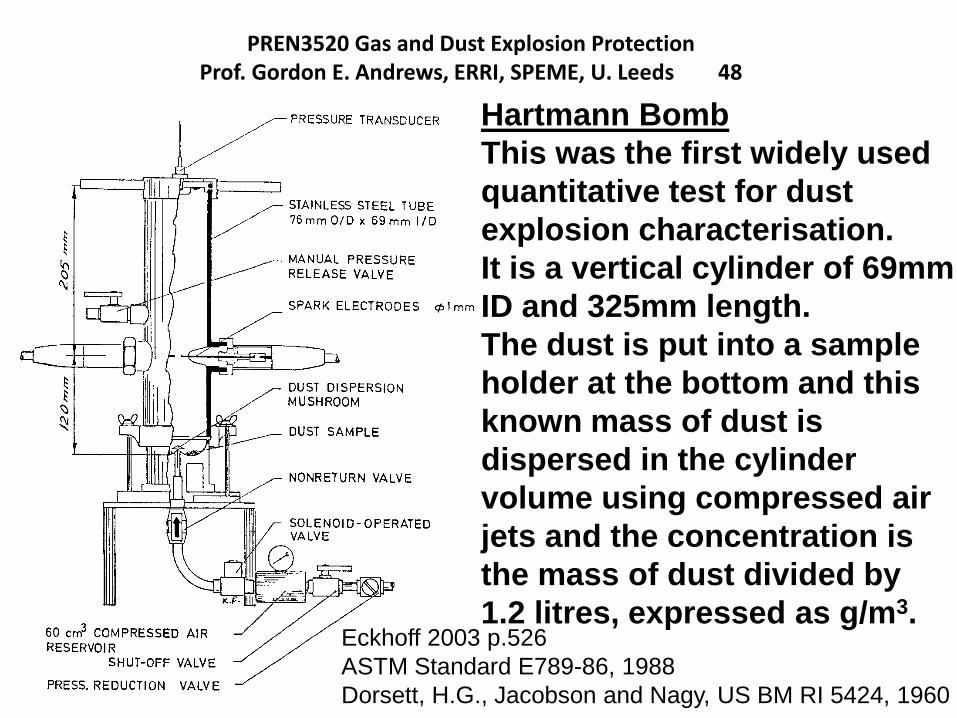
Hartmann Bomb
This was the first widely used
quantitative test for dust
explosion characterisation.
It is a vertical cylinder of 69mm
ID and 325mm length.
The dust is put into a sample
holder at the bottom and this
known mass of dust is
dispersed in the cylinder
volume using compressed air
jets and the concentration is
the mass of dust divided by
1.2 litres, expressed as g/m3.Eckhoff 2003 p.526
ASTM Standard E789-86, 1988
Dorsett, H.G., Jacobson and Nagy, US BM RI 5424, 1960
PREN3520 Gas and Dust Explosion ProtectionProf. Gordon E. Andrews, ERRI, SPEME, U. Leeds 49
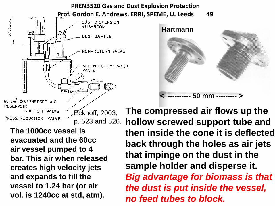
< ---------- 50 mm --------- >
The compressed air flows up the
hollow screwed support tube and
then inside the cone it is deflected
back through the holes as air jets
that impinge on the dust in the
sample holder and disperse it.
Big advantage for biomass is that
the dust is put inside the vessel,
no feed tubes to block.
Eckhoff, 2003,
p. 523 and 526.
Hartmann
The 1000cc vessel is
evacuated and the 60cc
air vessel pumped to 4
bar. This air when released
creates high velocity jets
and expands to fill the
vessel to 1.24 bar (or air
vol. is 1240cc at std, atm).
Pulverised biomass flame propagation and explosion characteristics: problems and solutions.
Prof. Gordon E. Andrews, Energy Research Institute, SCAPE, Univ. Leeds, UK
The Hartmann equipment is very similar to the European
Method T for the determination of the lean limit for gaseous
fuels.
This has an 80mm diameter tube that is 300mm long and
ignited at 60mm from the bottom. The flame is flammable if
it moves 100mm from the spark.
These dimensions are very similar to the Hartmann and the
difference in diameter will make no difference on gas LEL
results and hence, is unlikely to make a difference for dust
explosion MEC measurements
The use of the thermocouples as flame detectors in the
Leeds modification to this equipment enables a flame
movement to 100mm from the spark to be determined.
Hence the same criteria for MEC as LEL can be used.
United Kingdom Explosions Liaison Group, UKELG, meeting on Biomass Dust ExplosionsUniversity of Leeds, 23.9.2014
PREN3520 Gas and Dust Explosion ProtectionProf. Gordon E. Andrews, ERRI, SPEME, U. Leeds 51
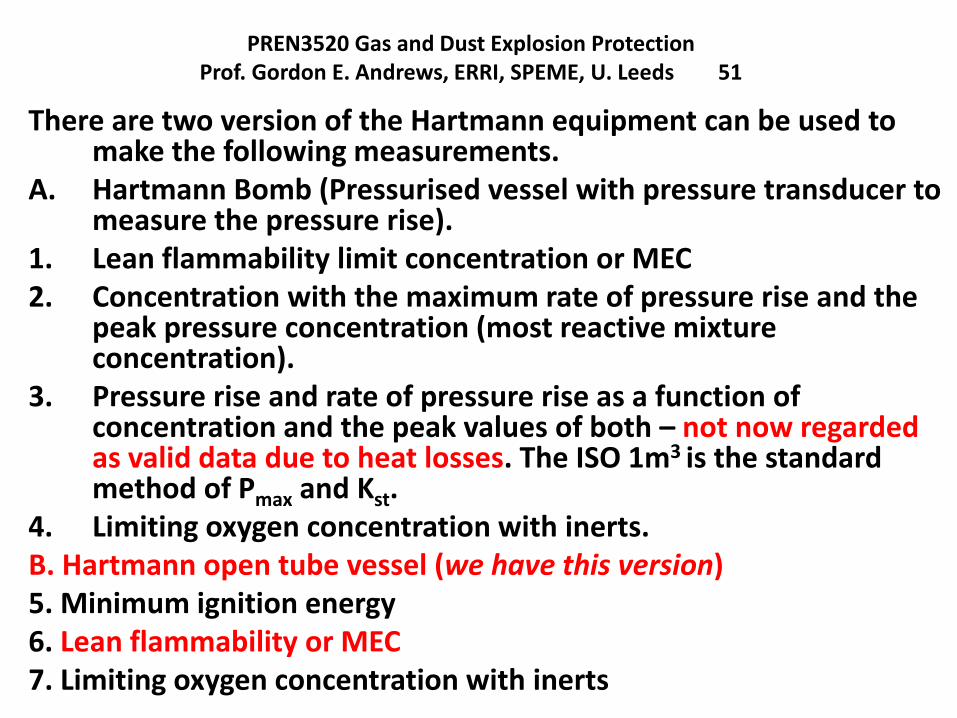
There are two version of the Hartmann equipment can be used to make the following measurements.
A. Hartmann Bomb (Pressurised vessel with pressure transducer to measure the pressure rise).
1. Lean flammability limit concentration or MEC2. Concentration with the maximum rate of pressure rise and the
peak pressure concentration (most reactive mixture concentration).
3. Pressure rise and rate of pressure rise as a function of concentration and the peak values of both – not now regarded as valid data due to heat losses. The ISO 1m3 is the standard method of Pmax and Kst.
4. Limiting oxygen concentration with inerts.B. Hartmann open tube vessel (we have this version)5. Minimum ignition energy6. Lean flammability or MEC7. Limiting oxygen concentration with inerts
Explosion Mitigation 2014Prof. Gordon E. Andrews, Energy Research Institute, U. Leeds, UK. 52
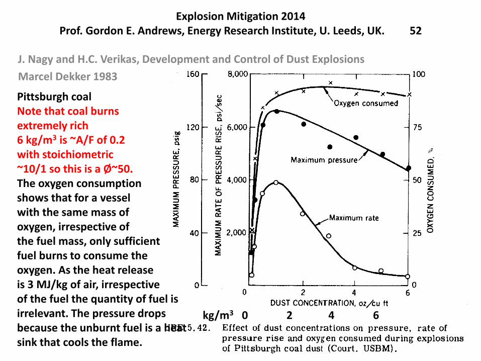
J. Nagy and H.C. Verikas, Development and Control of Dust Explosions
Marcel Dekker 1983
Pittsburgh coalNote that coal burnsextremely rich6 kg/m3 is ~A/F of 0.2with stoichiometric~10/1 so this is a Ø~50.The oxygen consumptionshows that for a vessel with the same mass ofoxygen, irrespective ofthe fuel mass, only sufficientfuel burns to consume theoxygen. As the heat releaseis 3 MJ/kg of air, irrespectiveof the fuel the quantity of fuel is irrelevant. The pressure drops because the unburnt fuel is a heat sink that cools the flame.
kg/m3 0 2 4 6
Gas and Dust Explosion Protection 2012Prof. Gordon E. Andrews, ERI, U. Leeds 53
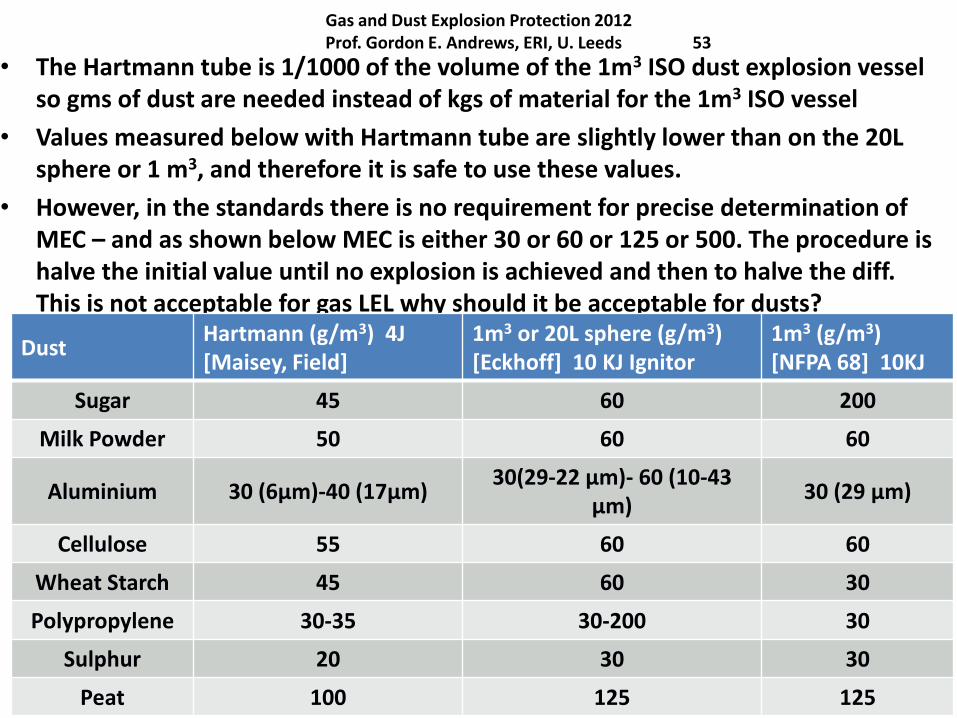
• The Hartmann tube is 1/1000 of the volume of the 1m3 ISO dust explosion vessel so gms of dust are needed instead of kgs of material for the 1m3 ISO vessel
• Values measured below with Hartmann tube are slightly lower than on the 20L sphere or 1 m3, and therefore it is safe to use these values.
• However, in the standards there is no requirement for precise determination of MEC – and as shown below MEC is either 30 or 60 or 125 or 500. The procedure ishalve the initial value until no explosion is achieved and then to halve the diff.This is not acceptable for gas LEL why should it be acceptable for dusts?
DustHartmann (g/m3) 4J [Maisey, Field]
1m3 or 20L sphere (g/m3) [Eckhoff] 10 KJ Ignitor
1m3 (g/m3) [NFPA 68] 10KJ
Sugar 45 60 200
Milk Powder 50 60 60
Aluminium 30 (6µm)-40 (17µm)30(29-22 µm)- 60 (10-43
µm)30 (29 µm)
Cellulose 55 60 60
Wheat Starch 45 60 30
Polypropylene 30-35 30-200 30
Sulphur 20 30 30
Peat 100 125 125
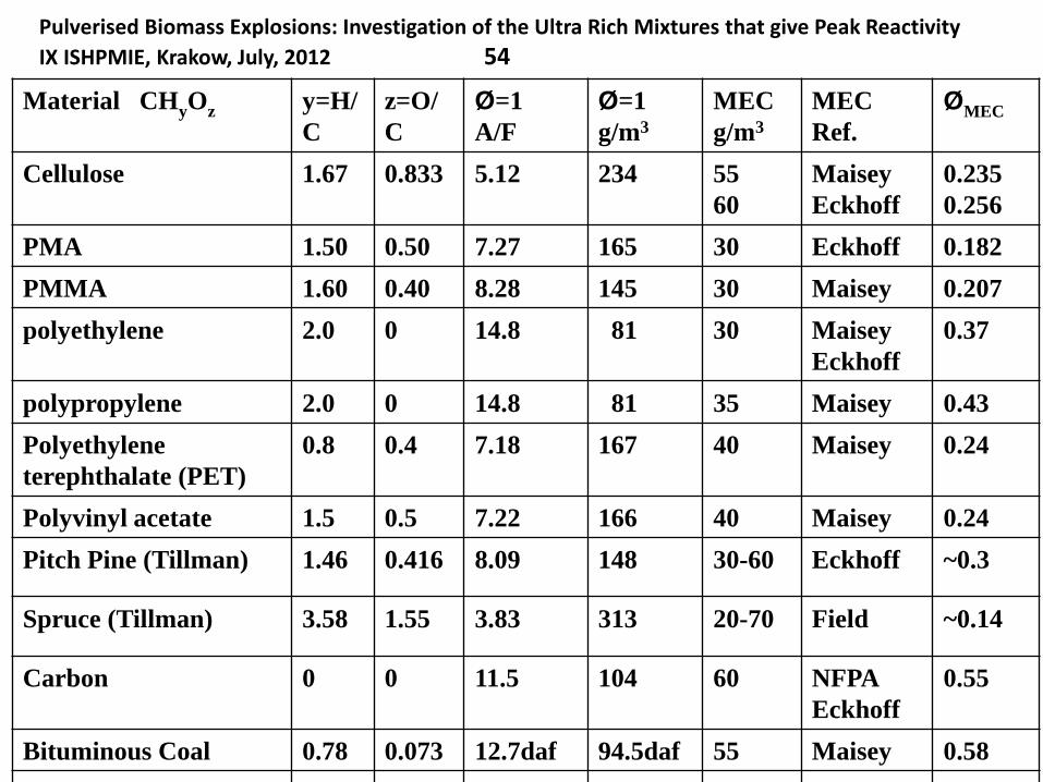
Pulverised Biomass Explosions: Investigation of the Ultra Rich Mixtures that give Peak Reactivity
IX ISHPMIE, Krakow, July, 2012 54
Material CHyOz y=H/
C
z=O/
C
Ø=1
A/F
Ø=1
g/m3
MEC
g/m3
MEC
Ref.
ØMEC
Cellulose 1.67 0.833 5.12 234 55
60
Maisey
Eckhoff
0.235
0.256
PMA 1.50 0.50 7.27 165 30 Eckhoff 0.182
PMMA 1.60 0.40 8.28 145 30 Maisey 0.207
polyethylene 2.0 0 14.8 81 30 Maisey
Eckhoff
0.37
polypropylene 2.0 0 14.8 81 35 Maisey 0.43
Polyethylene
terephthalate (PET)
0.8 0.4 7.18 167 40 Maisey 0.24
Polyvinyl acetate 1.5 0.5 7.22 166 40 Maisey 0.24
Pitch Pine (Tillman) 1.46 0.416 8.09 148 30-60 Eckhoff ~0.3
Spruce (Tillman) 3.58 1.55 3.83 313 20-70 Field ~0.14
Carbon 0 0 11.5 104 60 NFPA
Eckhoff
0.55
Bituminous Coal 0.78 0.073 12.7daf 94.5daf 55 Maisey 0.58
Pulverised biomass flame propagation and explosion characteristics with comparison with coal combustion.
Prof. Gordon E. Andrews, Energy Research Institute, SCAPE, Univ. Leeds, UK
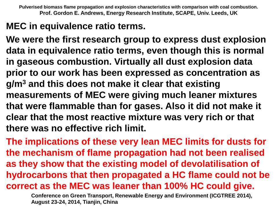
MEC in equivalence ratio terms.
We were the first research group to express dust explosion
data in equivalence ratio terms, even though this is normal
in gaseous combustion. Virtually all dust explosion data
prior to our work has been expressed as concentration as
g/m3 and this does not make it clear that existing
measurements of MEC were giving much leaner mixtures
that were flammable than for gases. Also it did not make it
clear that the most reactive mixture was very rich or that
there was no effective rich limit.
The implications of these very lean MEC limits for dusts for
the mechanism of flame propagation had not been realised
as they show that the existing model of devolatilisation of
hydrocarbons that then propagated a HC flame could not be
correct as the MEC was leaner than 100% HC could give. Conference on Green Transport, Renewable Energy and Environment (ICGTREE 2014), August 23-24, 2014, Tianjin, China
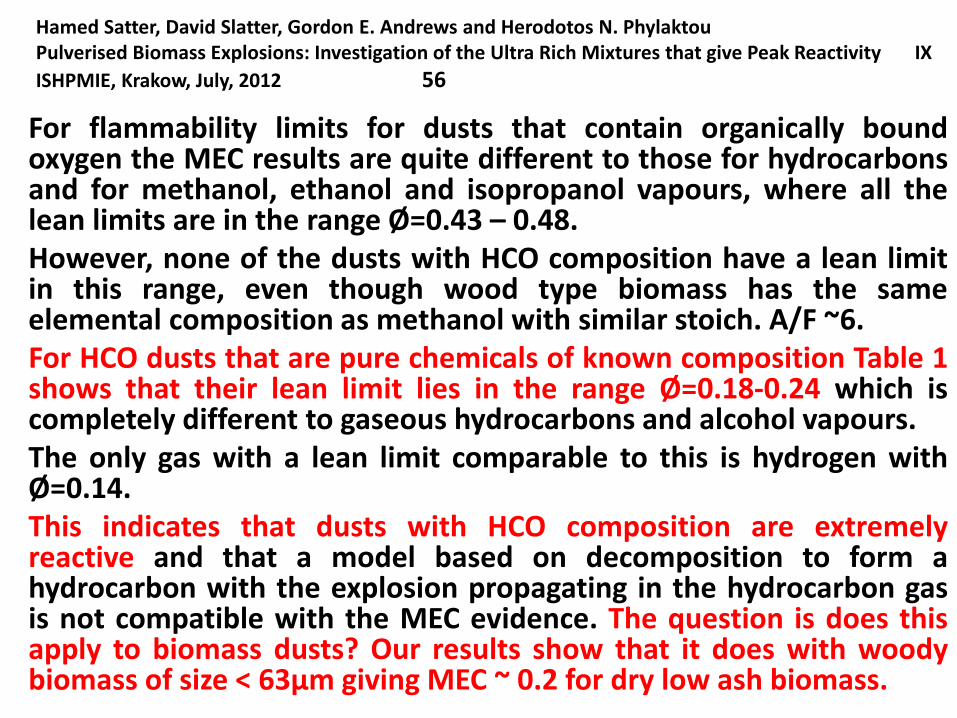
Hamed Satter, David Slatter, Gordon E. Andrews and Herodotos N. PhylaktouPulverised Biomass Explosions: Investigation of the Ultra Rich Mixtures that give Peak Reactivity IX
ISHPMIE, Krakow, July, 2012 56
For flammability limits for dusts that contain organically boundoxygen the MEC results are quite different to those for hydrocarbonsand for methanol, ethanol and isopropanol vapours, where all thelean limits are in the range Ø=0.43 – 0.48.However, none of the dusts with HCO composition have a lean limitin this range, even though wood type biomass has the sameelemental composition as methanol with similar stoich. A/F ~6.For HCO dusts that are pure chemicals of known composition Table 1shows that their lean limit lies in the range Ø=0.18-0.24 which iscompletely different to gaseous hydrocarbons and alcohol vapours.The only gas with a lean limit comparable to this is hydrogen withØ=0.14.This indicates that dusts with HCO composition are extremelyreactive and that a model based on decomposition to form ahydrocarbon with the explosion propagating in the hydrocarbon gasis not compatible with the MEC evidence. The question is does thisapply to biomass dusts? Our results show that it does with woodybiomass of size < 63µm giving MEC ~ 0.2 for dry low ash biomass.
PEME3521 and PEME5521M Gas and Dust Explosion Protection 2013
Prof. Gordon E. Andrews, ERRI, SPEME, U. Leeds 57
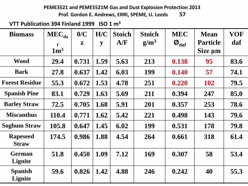
VTT Publication 394 Finland 1999 ISO 1 m3
Biomass MECda
f
1m3
0/C
z
H/C
y
Stoich
A/F
Stoich
g/m3
MEC
Ødaf
Mean
Particle
Size μm
VOF
daf
Wood 29.4 0.731 1.59 5.63 213 0.138 95 83.6
Bark 27.8 0.637 1.42 6.03 199 0.140 57 74.1
Forest Residue 55.3 0.672 1.53 4.78 251 0.220 102 79.5
Spanish Pine 83.1 0.729 1.63 5.69 211 0.394 247 85.0
Barley Straw 72.5 0.705 1.68 5.91 201 0.357 253 78.6
Miscanthus 110.4 0.771 1.62 5.42 221 0.498 143 79.6
Soghum Straw 105.8 0.647 1.45 6.02 199 0.531 178 79.8
Rapeseed
Straw174.5 0.986 1.88 4.54 264 0.661 318 61.4
German
Lignite51.8 0.450 1.09 7.12 169 0.307 58 53.4
Spanish
Lignite59.6 0.826 1.42 4.88 246 0.242 40 55.3
Pulverised biomass flame propagation and explosion characteristics: problems and solutions.
Prof. Gordon E. Andrews, Energy Research Institute, SCAPE, Univ. Leeds, UK
Contents
1. Introduction
2. Some characteristics of biomass – particle size.
3. Biomass stoichiometry and variable composition
4. Problems with biomass explosion characterisation.
5. Dust explosion characterisation equipment.
Hartmann for MEC
20L sphere
ISO 1 m3
5. The unburned particle mass in the ISO 1m3
6. Modifications of the ISO 1 m3 vessel for woody biomass.
7. Leeds MEC results for woody biomass
8. Leeds ISO 1 m3 vessel results for biomass (Clara
Huescar Medina will present this in the next lecture).
United Kingdom Explosions Liaison Group, UKELG, meeting on Biomass Dust ExplosionsUniversity of Leeds, 23.9.2014
PREN3520 Gas and Dust Explosion ProtectionProf. Gordon E. Andrews, ERRI, SPEME, U. Leeds 59
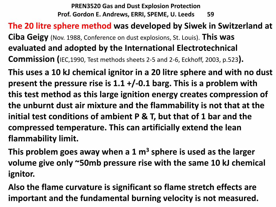
The 20 litre sphere method was developed by Siwek in Switzerland at Ciba Geigy (Nov. 1988, Conference on dust explosions, St. Louis). This was evaluated and adopted by the International ElectrotechnicalCommission (IEC,1990, Test methods sheets 2-5 and 2-6, Eckhoff, 2003, p.523).
This uses a 10 kJ chemical ignitor in a 20 litre sphere and with no dust present the pressure rise is 1.1 +/-0.1 barg. This is a problem with this test method as this large ignition energy creates compression of the unburnt dust air mixture and the flammability is not that at the initial test conditions of ambient P & T, but that of 1 bar and the compressed temperature. This can artificially extend the lean flammability limit.
This problem goes away when a 1 m3 sphere is used as the larger volume give only ~50mb pressure rise with the same 10 kJ chemical ignitor.
Also the flame curvature is significant so flame stretch effects are important and the fundamental burning velocity is not measured.
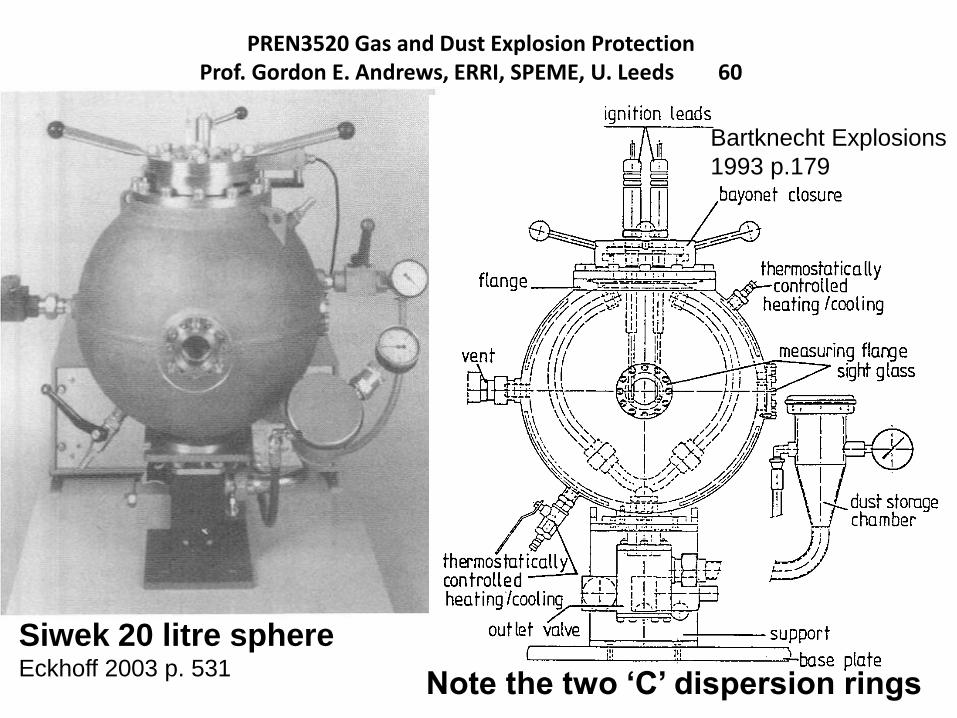
PREN3520 Gas and Dust Explosion ProtectionProf. Gordon E. Andrews, ERRI, SPEME, U. Leeds 60
Siwek 20 litre sphereEckhoff 2003 p. 531
Note the two ‘C’ dispersion rings
Bartknecht Explosions
1993 p.179
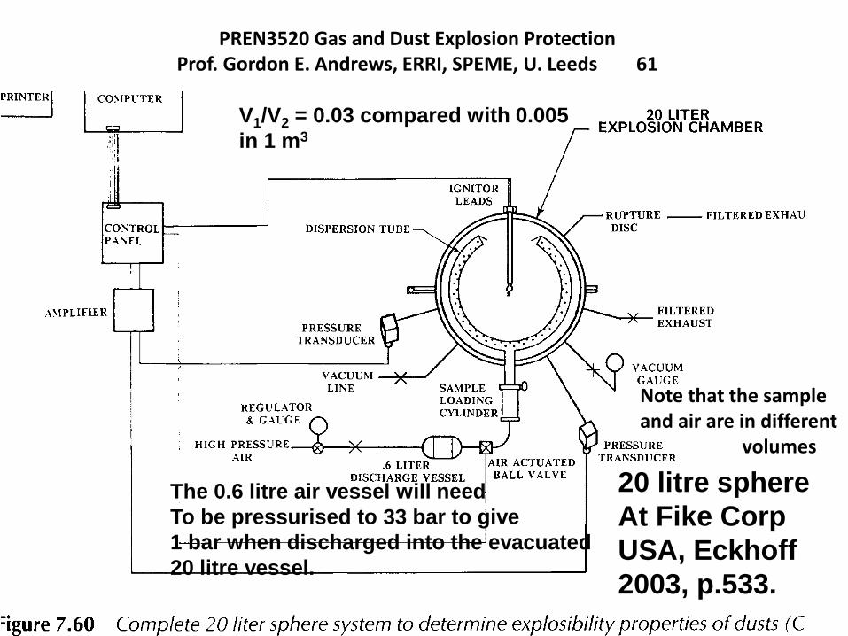
PREN3520 Gas and Dust Explosion ProtectionProf. Gordon E. Andrews, ERRI, SPEME, U. Leeds 61
20 litre sphere
At Fike Corp
USA, Eckhoff
2003, p.533.
The 0.6 litre air vessel will need
To be pressurised to 33 bar to give
1 bar when discharged into the evacuated
20 litre vessel.
Note that the sampleand air are in different
volumes
V1/V2 = 0.03 compared with 0.005
in 1 m3
Explosion Mitigation 2013Prof. Gordon E. Andrews, Energy Research Insitute, U. Leeds, UK. 62
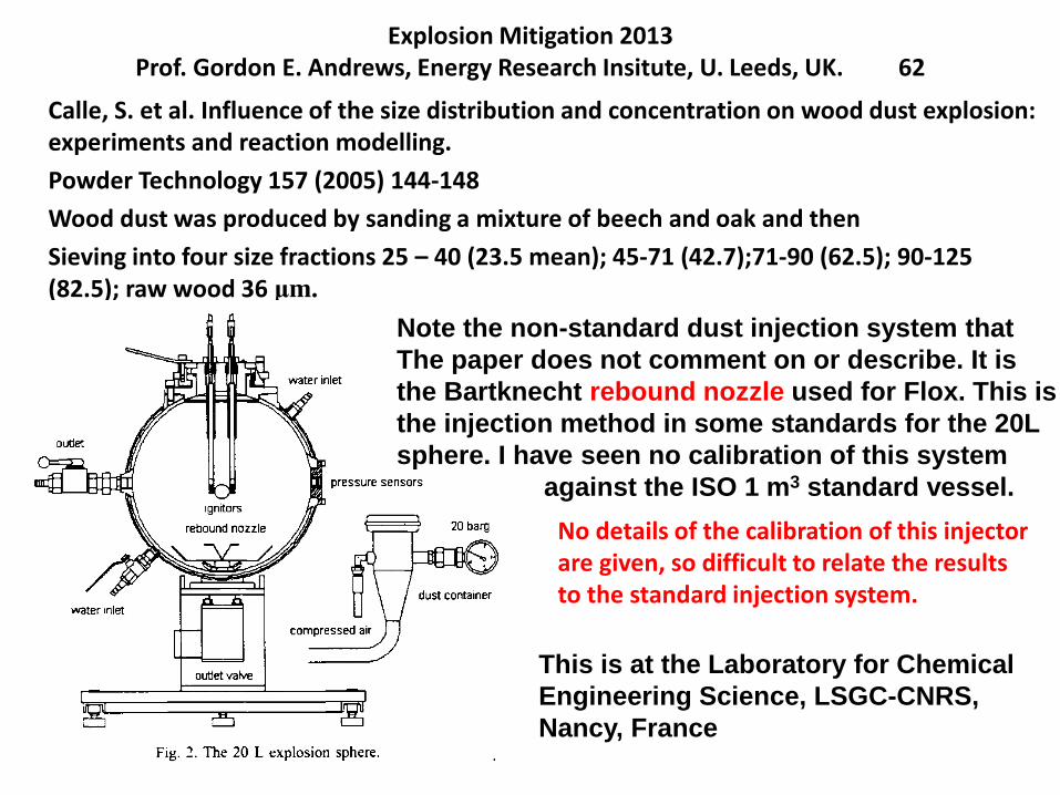
Calle, S. et al. Influence of the size distribution and concentration on wood dust explosion: experiments and reaction modelling.
Powder Technology 157 (2005) 144-148
Wood dust was produced by sanding a mixture of beech and oak and then
Sieving into four size fractions 25 – 40 (23.5 mean); 45-71 (42.7);71-90 (62.5); 90-125 (82.5); raw wood 36 μm.
Note the non-standard dust injection system that
The paper does not comment on or describe. It is
the Bartknecht rebound nozzle used for Flox. This is
the injection method in some standards for the 20L
sphere. I have seen no calibration of this system
against the ISO 1 m3 standard vessel.
This is at the Laboratory for Chemical
Engineering Science, LSGC-CNRS,
Nancy, France
No details of the calibration of this injectorare given, so difficult to relate the resultsto the standard injection system.
Pulverised biomass flame propagation and explosion characteristics: problems and solutions.
Prof. Gordon E. Andrews, Energy Research Institute, SCAPE, Univ. Leeds, UK
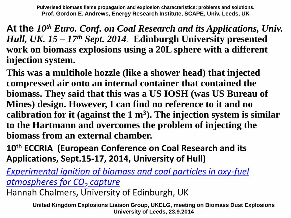
At the 10th Euro. Conf. on Coal Research and its Applications, Univ. Hull, UK. 15 – 17th Sept. 2014. Edinburgh University presented work on biomass explosions using a 20L sphere with a different injection system.
This was a multihole hozzle (like a shower head) that injected compressed air onto an internal container that contained the biomass. They said that this was a US IOSH (was US Bureau of Mines) design. However, I can find no reference to it and no calibration for it (against the 1 m3). The injection system is similar to the Hartmann and overcomes the problem of injecting the biomass from an external chamber.
10th ECCRIA (European Conference on Coal Research and its Applications, Sept.15-17, 2014, University of Hull)
Experimental ignition of biomass and coal particles in oxy-fuel atmospheres for CO2 captureHannah Chalmers, University of Edinburgh, UK
United Kingdom Explosions Liaison Group, UKELG, meeting on Biomass Dust ExplosionsUniversity of Leeds, 23.9.2014
Gas and Dust Explosion Protection 2011
Prof. Gordon E. Andrews, ERRI, SPEME, U. Leeds 64
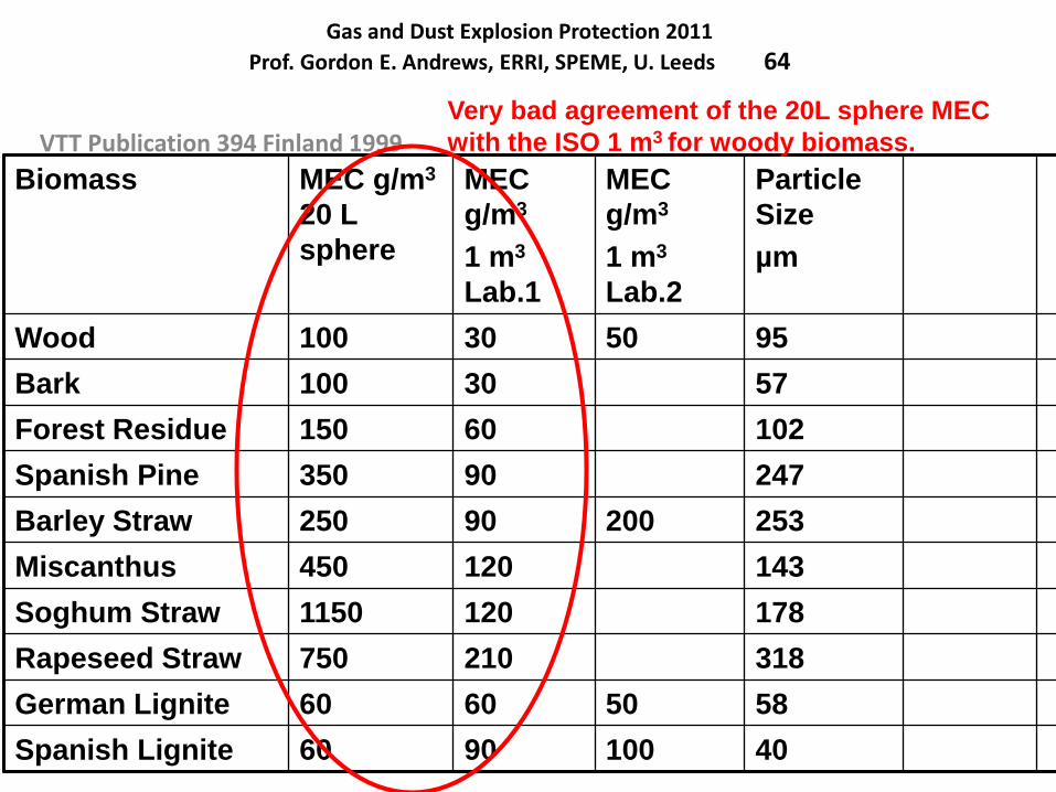
VTT Publication 394 Finland 1999
Biomass MEC g/m3
20 L
sphere
MEC
g/m3
1 m3
Lab.1
MEC
g/m3
1 m3
Lab.2
Particle
Size
µm
Wood 100 30 50 95
Bark 100 30 57
Forest Residue 150 60 102
Spanish Pine 350 90 247
Barley Straw 250 90 200 253
Miscanthus 450 120 143
Soghum Straw 1150 120 178
Rapeseed Straw 750 210 318
German Lignite 60 60 50 58
Spanish Lignite 60 90 100 40
Very bad agreement of the 20L sphere MEC
with the ISO 1 m3 for woody biomass.
PEME3521 and PEME5521M Gas and Dust Explosion Protection 2011
Prof. Gordon E. Andrews, ERRI, SPEME, U. Leeds 65
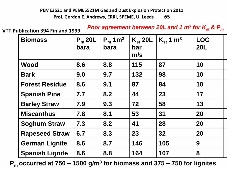
VTT Publication 394 Finland 1999
Biomass Pm 20L
bara
Pm 1m3
bara
Kst 20L
bar
m/s
Kst 1 m3 LOC
20L
Wood 8.6 8.8 115 87 10
Bark 9.0 9.7 132 98 10
Forest Residue 8.6 9.1 87 84 10
Spanish Pine 7.7 8.2 44 23 17
Barley Straw 7.9 9.3 72 58 13
Miscanthus 7.8 8.1 53 31 20
Soghum Straw 7.3 8.2 41 28 20
Rapeseed Straw 6.7 8.3 23 32 20
German Lignite 8.6 8.7 146 105 9
Spanish Lignite 8.6 8.8 164 107 8
Pm occurred at 750 – 1500 g/m3 for biomass and 375 – 750 for lignites
Poor agreement between 20L and 1 m3 for Kst & Pm
Pulverised biomass flame propagation and explosion characteristics: problems and solutions.
Prof. Gordon E. Andrews, Energy Research Institute, SCAPE, Univ. Leeds, UK
Contents
1. Introduction
2. Some characteristics of biomass – particle size.
3. Biomass stoichiometry and variable composition
4. Problems with biomass explosion characterisation.
5. Dust explosion characterisation equipment.
Hartmann for MEC
20L sphere
ISO 1 m3
5. The unburned particle mass in the ISO 1m3
6. Modifications of the ISO 1 m3 vessel for woody biomass.
7. Leeds MEC results for woody biomass
8. Leeds ISO 1 m3 vessel results for biomass (Clara
Huescar Medina will present this in the next lecture).
United Kingdom Explosions Liaison Group, UKELG, meeting on Biomass Dust ExplosionsUniversity of Leeds, 23.9.2014
Gas and Dust Explosion ProtectionProf. Gordon E. Andrews, ERRI, SPEME, U. Leeds 67
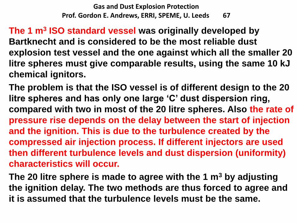
The 1 m3 ISO standard vessel was originally developed by
Bartknecht and is considered to be the most reliable dust
explosion test vessel and the one against which all the smaller 20
litre spheres must give comparable results, using the same 10 kJ
chemical ignitors.
The problem is that the ISO vessel is of different design to the 20
litre spheres and has only one large ‘C’ dust dispersion ring,
compared with two in most of the 20 litre spheres. Also the rate of
pressure rise depends on the delay between the start of injection
and the ignition. This is due to the turbulence created by the
compressed air injection process. If different injectors are used
then different turbulence levels and dust dispersion (uniformity)
characteristics will occur.
The 20 litre sphere is made to agree with the 1 m3 by adjusting
the ignition delay. The two methods are thus forced to agree and
it is assumed that the turbulence levels must be the same.
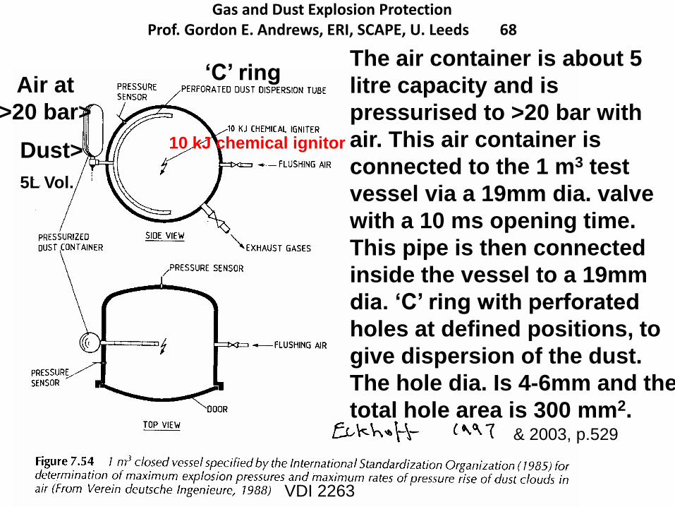
Gas and Dust Explosion ProtectionProf. Gordon E. Andrews, ERI, SCAPE, U. Leeds 68
The air container is about 5
litre capacity and is
pressurised to >20 bar with
air. This air container is
connected to the 1 m3 test
vessel via a 19mm dia. valve
with a 10 ms opening time.
This pipe is then connected
inside the vessel to a 19mm
dia. ‘C’ ring with perforated
holes at defined positions, to
give dispersion of the dust.
The hole dia. Is 4-6mm and the
total hole area is 300 mm2.& 2003, p.529
VDI 2263
Air at
>20 bar>
Dust>
‘C’ ring
10 kJ chemical ignitor
5L Vol.
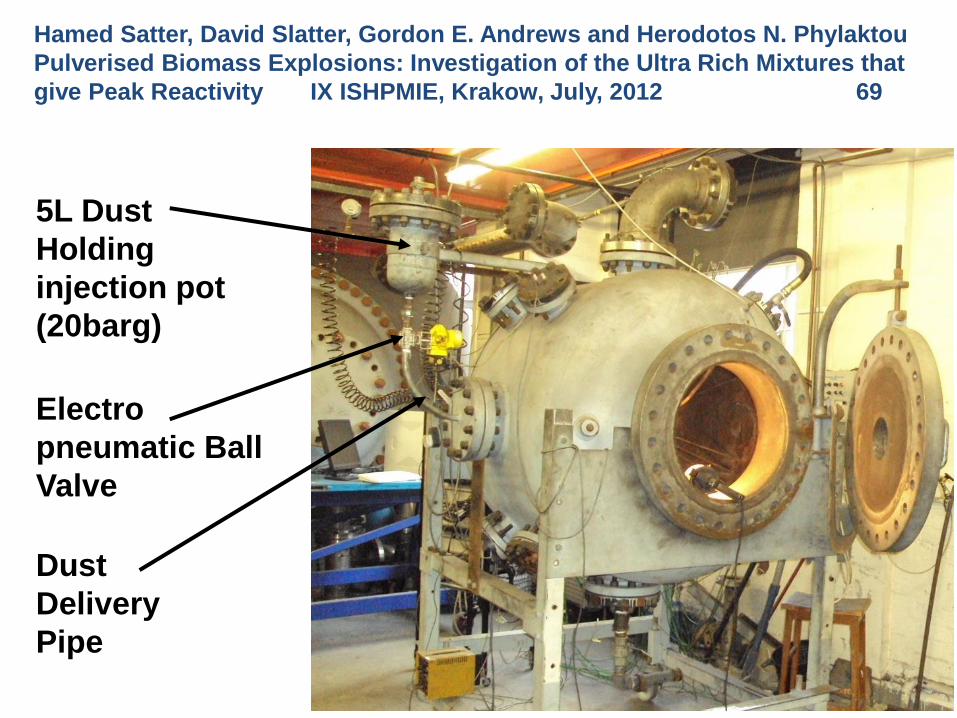
5L Dust
Holding
injection pot
(20barg)
Electro
pneumatic Ball
Valve
Dust
Delivery
Pipe
The Leeds ISO 1m3 Dust Explosion
Equipment
Hamed Satter, David Slatter, Gordon E. Andrews and Herodotos N. Phylaktou
Pulverised Biomass Explosions: Investigation of the Ultra Rich Mixtures that
give Peak Reactivity IX ISHPMIE, Krakow, July, 2012 69
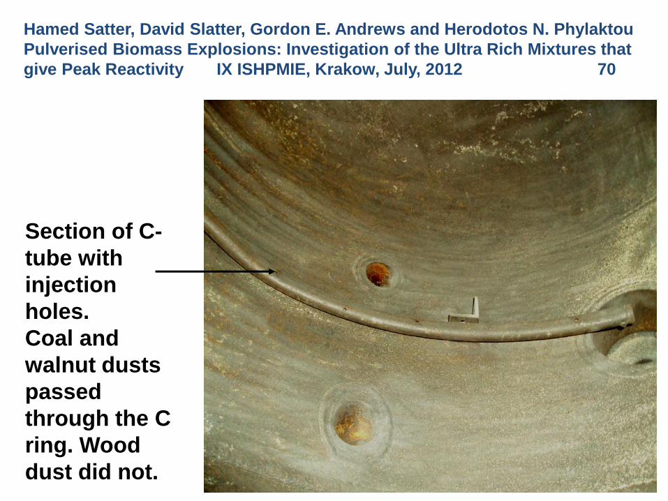
Section of C-
tube with
injection
holes.
Coal and
walnut dusts
passed
through the C
ring. Wood
dust did not.
Dust Injection System Inside the
Vessel – the Standard ‘C’ Dust
Dispersion Ring
Hamed Satter, David Slatter, Gordon E. Andrews and Herodotos N. Phylaktou
Pulverised Biomass Explosions: Investigation of the Ultra Rich Mixtures that
give Peak Reactivity IX ISHPMIE, Krakow, July, 2012 70
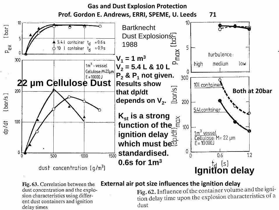
Gas and Dust Explosion ProtectionProf. Gordon E. Andrews, ERRI, SPEME, U. Leeds 71
Bartknecht
Dust Explosions
1988
Ignition delay
V1 = 1 m3
V2 = 5.4 L & 10 L
P2 & P1 not given.
Results show
that dp/dt
depends on V2.
22 µm Cellulose Dust
External air pot size influences the ignition delay
Kst is a strong
function of the
ignition delay
which must be
standardised.
0.6s for 1m3
Both at 20bar
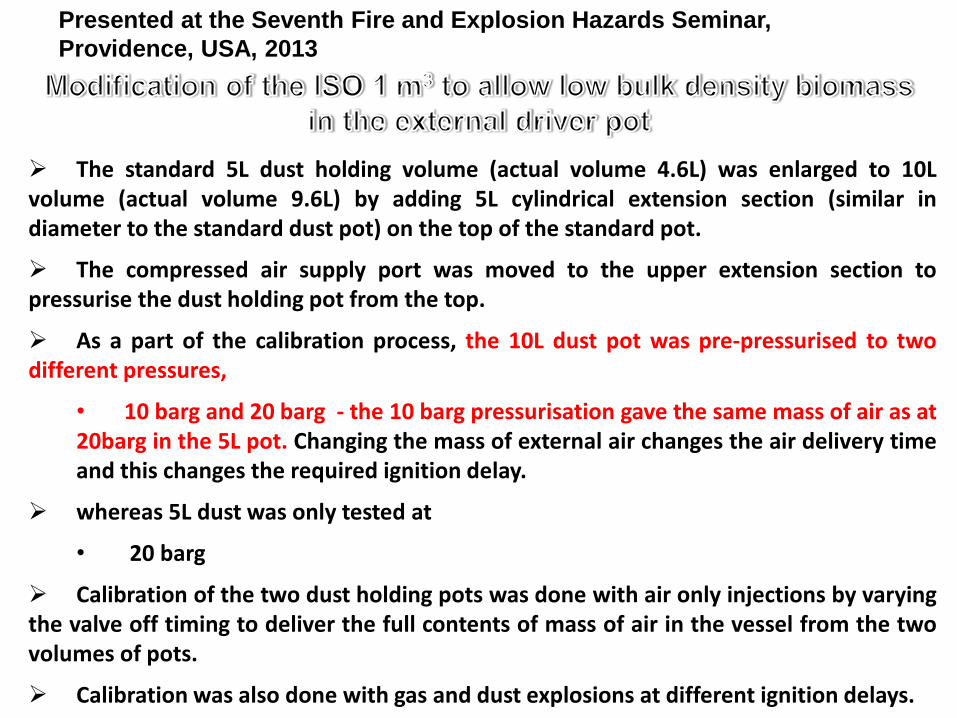
The standard 5L dust holding volume (actual volume 4.6L) was enlarged to 10Lvolume (actual volume 9.6L) by adding 5L cylindrical extension section (similar indiameter to the standard dust pot) on the top of the standard pot.
The compressed air supply port was moved to the upper extension section topressurise the dust holding pot from the top.
As a part of the calibration process, the 10L dust pot was pre-pressurised to twodifferent pressures,
• 10 barg and 20 barg - the 10 barg pressurisation gave the same mass of air as at20barg in the 5L pot. Changing the mass of external air changes the air delivery timeand this changes the required ignition delay.
whereas 5L dust was only tested at
• 20 barg
Calibration of the two dust holding pots was done with air only injections by varyingthe valve off timing to deliver the full contents of mass of air in the vessel from the twovolumes of pots.
Calibration was also done with gas and dust explosions at different ignition delays.
Presented at the Seventh Fire and Explosion Hazards Seminar,
Providence, USA, 2013
0.45 0.50 0.55 0.60 0.65 0.70 0.75 0.80 0.8520
40
60
80
100
120
7.5
8.0
8.5
9.0
9.5
10.0
10L dust pot - 10 barg
(Valve off - 0.65s)
5L dust pot - 20 barg
(Valve off - 0.65s)
10L dust pot - 20 barg
(Valve off - 0.50s)
C-tube (5L dust pot - 20 barg) - Valve timing = 0.50s
C-tube (10L dust pot - 20 barg) - Valve timing = 0.50s
C-tube (5Ldust pot - 20 barg) - Valve timing = 0.65s
C-tube (10L dust pot - 10 barg) - Valve timing = 0.65s
P max
/Pi
K st (b
ar m
/s)
Ignition Delay (s)
5L dust pot - 20 barg
(Valve off - 0.50s)
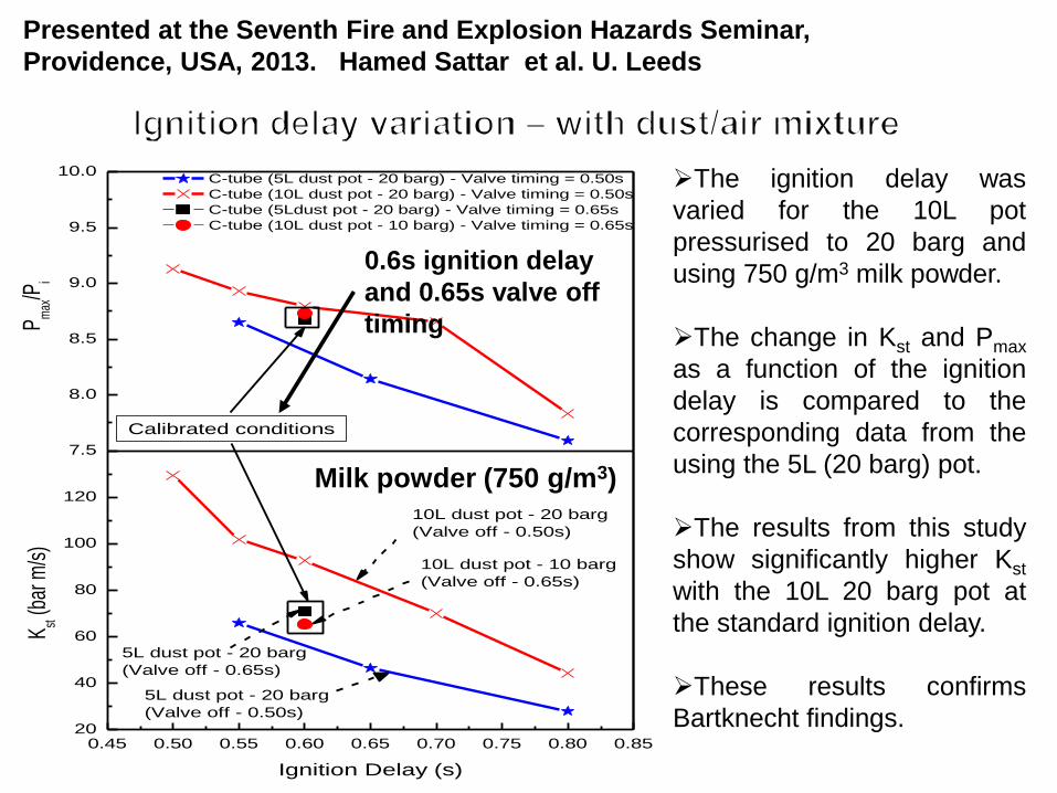
Calibrated conditions
The ignition delay was
varied for the 10L pot
pressurised to 20 barg and
using 750 g/m3 milk powder.
The change in Kst and Pmax
as a function of the ignition
delay is compared to the
corresponding data from the
using the 5L (20 barg) pot.
The results from this study
show significantly higher Kst
with the 10L 20 barg pot at
the standard ignition delay.
These results confirms
Bartknecht findings.
Milk powder (750 g/m3)
0.6s ignition delay
and 0.65s valve off
timing
Presented at the Seventh Fire and Explosion Hazards Seminar,
Providence, USA, 2013. Hamed Sattar et al. U. Leeds
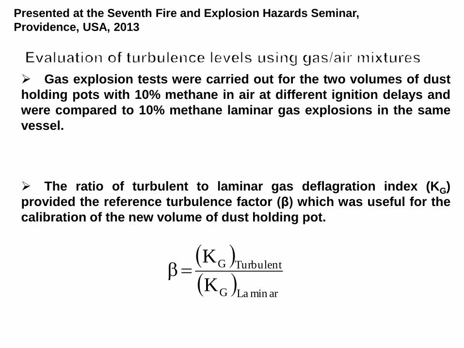
Gas explosion tests were carried out for the two volumes of dust
holding pots with 10% methane in air at different ignition delays and
were compared to 10% methane laminar gas explosions in the same
vessel.
The ratio of turbulent to laminar gas deflagration index (KG)
provided the reference turbulence factor (β) which was useful for the
calibration of the new volume of dust holding pot.
arminLaG
TurbulentG
K
K
Presented at the Seventh Fire and Explosion Hazards Seminar,
Providence, USA, 2013
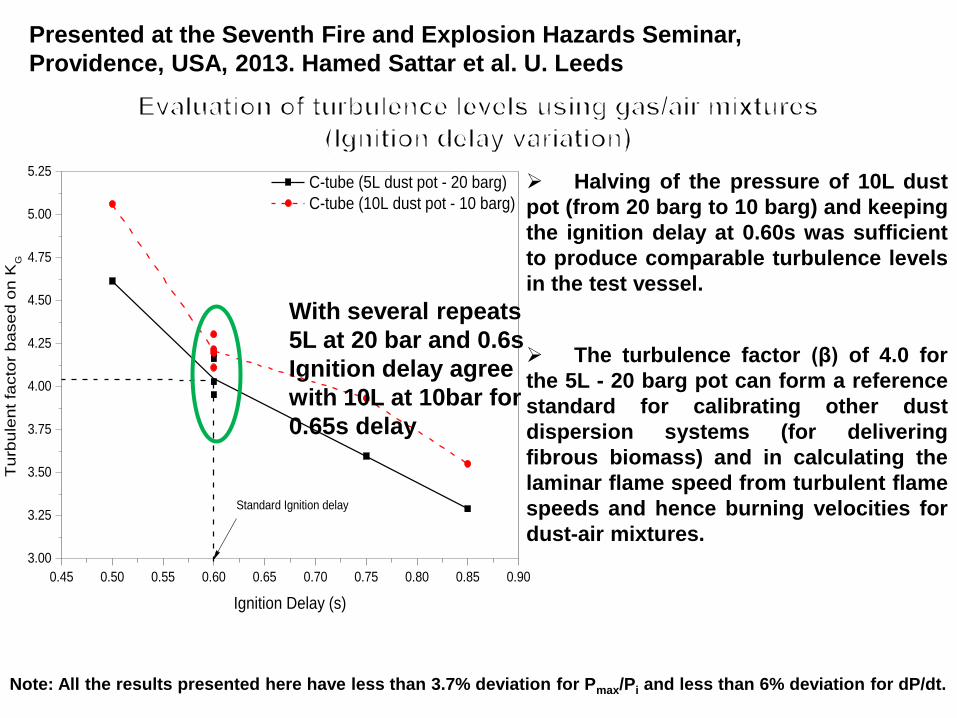
Note: All the results presented here have less than 3.7% deviation for Pmax/Pi and less than 6% deviation for dP/dt.
Halving of the pressure of 10L dust
pot (from 20 barg to 10 barg) and keeping
the ignition delay at 0.60s was sufficient
to produce comparable turbulence levels
in the test vessel.
The turbulence factor (β) of 4.0 for
the 5L - 20 barg pot can form a reference
standard for calibrating other dust
dispersion systems (for delivering
fibrous biomass) and in calculating the
laminar flame speed from turbulent flame
speeds and hence burning velocities for
dust-air mixtures.
0.45 0.50 0.55 0.60 0.65 0.70 0.75 0.80 0.85 0.90
3.00
3.25
3.50
3.75
4.00
4.25
4.50
4.75
5.00
5.25
C-tube (5L dust pot - 20 barg)
C-tube (10L dust pot - 10 barg)
Tu
rbu
len
t fa
cto
r b
ase
d o
n K
G
Ignition Delay (s)
Standard Ignition delay
Presented at the Seventh Fire and Explosion Hazards Seminar,
Providence, USA, 2013. Hamed Sattar et al. U. Leeds
With several repeats
5L at 20 bar and 0.6s
Ignition delay agree
with 10L at 10bar for
0.65s delay
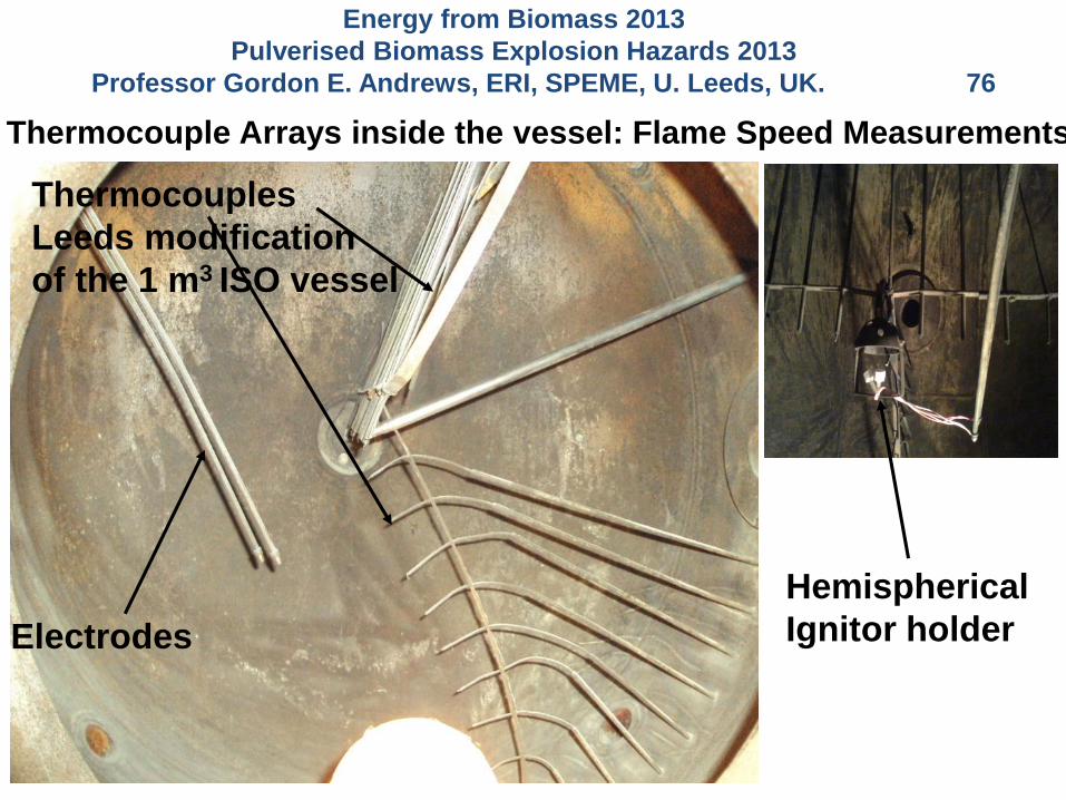
Electrodes
Thermocouples
Leeds modification
of the 1 m3 ISO vessel
Hemispherical
Ignitor holder
Thermocouple Arrays inside the vessel: Flame Speed Measurements
Energy from Biomass 2013
Pulverised Biomass Explosion Hazards 2013
Professor Gordon E. Andrews, ERI, SPEME, U. Leeds, UK. 76
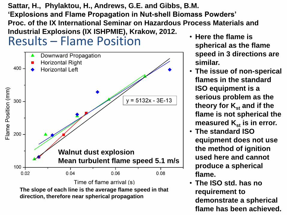
Results – Flame Position
The slope of each line is the average flame speed in that
direction, therefore near spherical propagation
• Here the flame is
spherical as the flame
speed in 3 directions are
similar.
• The issue of non-sperical
flames in the standard
ISO equipment is a
serious problem as the
theory for Kst and if the
flame is not spherical the
measured Kst is in error.
• The standard ISO
equipment does not use
the method of ignition
used here and cannot
produce a spherical
flame.
• The ISO std. has no
requirement to
demonstrate a spherical
flame has been achieved.
Walnut dust explosion
Mean turbulent flame speed 5.1 m/s
Sattar, H., Phylaktou, H., Andrews, G.E. and Gibbs, B.M.
‘Explosions and Flame Propagation in Nut-shell Biomass Powders’
Proc. of the IX International Seminar on Hazardous Process Materials and
Industrial Explosions (IX ISHPMIE), Krakow, 2012.
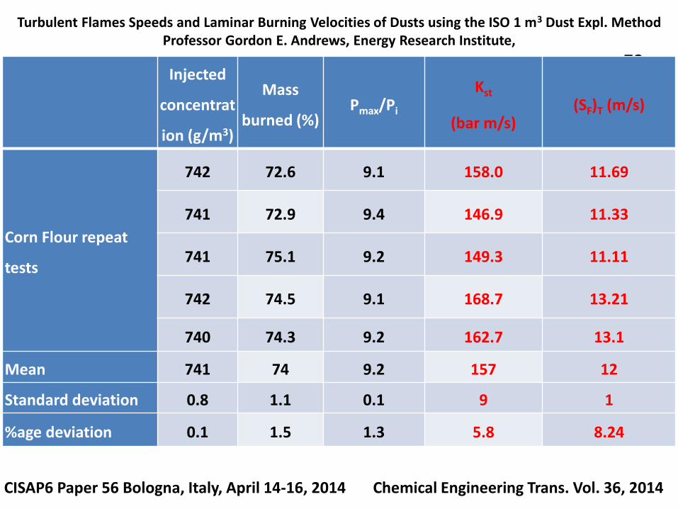
Turbulent Flames Speeds and Laminar Burning Velocities of Dusts using the ISO 1 m3 Dust Expl. MethodProfessor Gordon E. Andrews, Energy Research Institute,
School of Chemical and Process Eng., U. Leeds , UK 78
CISAP6 Paper 56 Bologna, Italy, April 14-16, 2014 Chemical Engineering Trans. Vol. 36, 2014
Injected
concentrat
ion (g/m3)
Mass
burned (%)Pmax/Pi
Kst
(bar m/s)(SF)T (m/s)
Corn Flour repeat
tests
742 72.6 9.1 158.0 11.69
741 72.9 9.4 146.9 11.33
741 75.1 9.2 149.3 11.11
742 74.5 9.1 168.7 13.21
740 74.3 9.2 162.7 13.1
Mean 741 74 9.2 157 12
Standard deviation 0.8 1.1 0.1 9 1
%age deviation 0.1 1.5 1.3 5.8 8.24
Turbulent Flames Speeds and Laminar Burning Velocities of Dusts using the ISO 1 m3 Dust Expl. MethodProfessor Gordon E. Andrews, Energy Research Institute,
School of Chemical and Process Eng., U. Leeds , UK 79
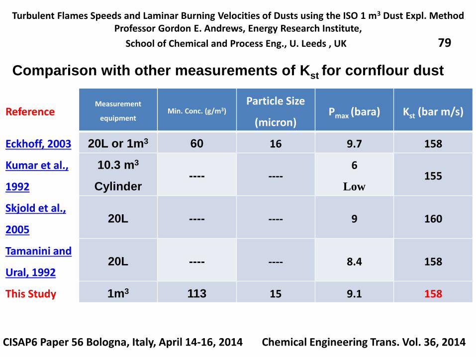
Comparison with other measurements of Kst for cornflour dust
CISAP6 Paper 56 Bologna, Italy, April 14-16, 2014 Chemical Engineering Trans. Vol. 36, 2014
ReferenceMeasurement
equipmentMin. Conc. (g/m3)
Particle Size
(micron)Pmax (bara) Kst (bar m/s)
Eckhoff, 2003 20L or 1m3 60 16 9.7 158
Kumar et al.,
1992
10.3 m3
Cylinder---- ----
6
Low155
Skjold et al.,
200520L ---- ---- 9 160
Tamanini and
Ural, 199220L ---- ---- 8.4 158
This Study 1m3 113 15 9.1 158
Turbulent Flames Speeds and Laminar Burning Velocities of Dusts using the ISO 1 m3 Dust Expl. MethodProfessor Gordon E. Andrews, Energy Research Institute,
School of Chemical and Process Eng., U. Leeds , UK 80
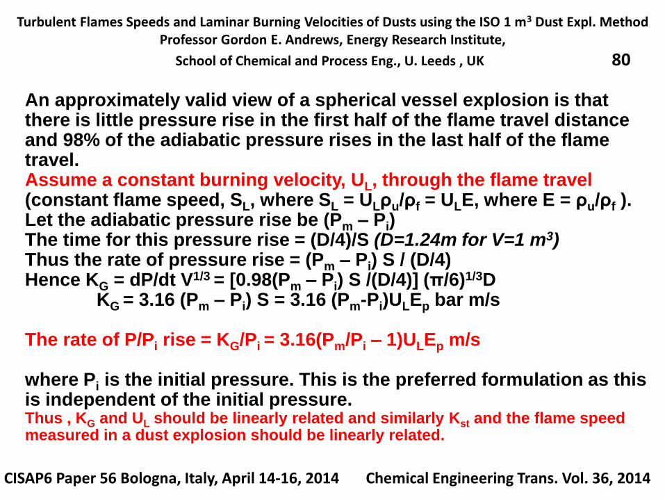
An approximately valid view of a spherical vessel explosion is that there is little pressure rise in the first half of the flame travel distance and 98% of the adiabatic pressure rises in the last half of the flame travel.Assume a constant burning velocity, UL, through the flame travel (constant flame speed, SL, where SL = ULρu/ρf = ULE, where E = ρu/ρf ).Let the adiabatic pressure rise be (Pm – Pi) The time for this pressure rise = (D/4)/S (D=1.24m for V=1 m3)Thus the rate of pressure rise = (Pm – Pi) S / (D/4)Hence KG = dP/dt V1/3 = [0.98(Pm – Pi) S /(D/4)] (π/6)1/3D
KG = 3.16 (Pm – Pi) S = 3.16 (Pm-Pi)ULEp bar m/s
The rate of P/Pi rise = KG/Pi = 3.16(Pm/Pi – 1)ULEp m/s
where Pi is the initial pressure. This is the preferred formulation as this is independent of the initial pressure.Thus , KG and UL should be linearly related and similarly Kst and the flame speedmeasured in a dust explosion should be linearly related.
CISAP6 Paper 56 Bologna, Italy, April 14-16, 2014 Chemical Engineering Trans. Vol. 36, 2014
Turbulent Flames Speeds and Laminar Burning Velocities of Dusts using the ISO 1 m3 Dust Expl. MethodProfessor Gordon E. Andrews, Energy Research Institute,
School of Chemical and Process Eng., U. Leeds , UK 81
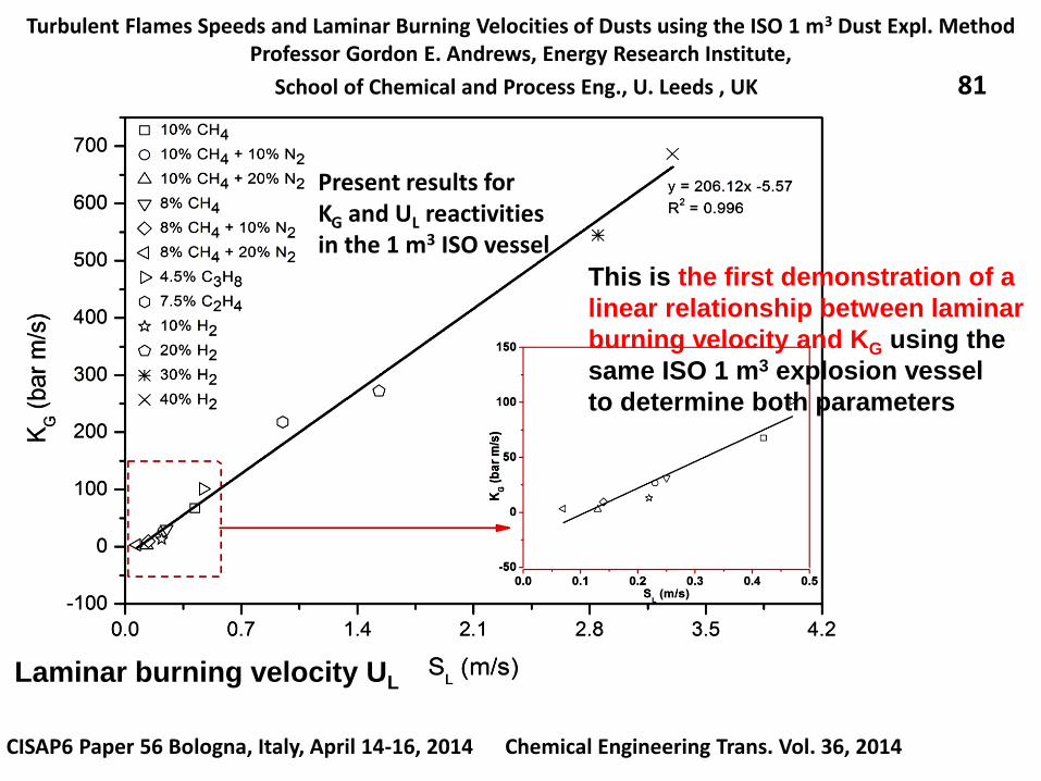
CISAP6 Paper 56 Bologna, Italy, April 14-16, 2014 Chemical Engineering Trans. Vol. 36, 2014
This is the first demonstration of a
linear relationship between laminar
burning velocity and KG using the
same ISO 1 m3 explosion vessel
to determine both parameters
Laminar burning velocity UL
Present results forKG and UL reactivitiesin the 1 m3 ISO vessel
Turbulent Flames Speeds and Laminar Burning Velocities of Dusts using the ISO 1 m3 Dust Expl. MethodProfessor Gordon E. Andrews, Energy Research Institute,
School of Chemical and Process Eng., U. Leeds , UK 82
It is proposed that the dust ISO standard explosion vessel to be used to
measure laminar burning velocities.
For dusts the turbulent flame speed would be measured and the laminar
flame speed calculated from the knowledge of the turbulence enhancement
factor β = 4 in the ISO standard air injection method for dust explosions.
This was evaluated by carrying out laminar and turbulent gas explosions in
the vessel
UL = Ss/βEpwhere UL is the laminar burning velocity
Ss is the measured laminar flame speed in the
constant pressure period of the explosion (up to
65% of the radius of the vessel)
Ep is the flame adiabatic expansion ratio at constant
pressure
β Turbulence factor evaluated from gas explosions in the ISO 1 m3 dust explosion vessel
This equation is valid for an infinitely thin reaction zone. The key issue is at
what size of flame is the infinitely thin reaction zone assumption valid. This
was determined using gas explosions, but could have to be larger for dust
explosions.
CISAP6 Paper 56 Bologna, Italy, April 14-16, 2014 Chemical Engineering Trans. Vol. 36, 2014
Turbulent Flames Speeds and Laminar Burning Velocities of Dusts using the ISO 1 m3 Dust Expl. MethodProfessor Gordon E. Andrews, Energy Research Institute,
School of Chemical and Process Eng., U. Leeds , UK 83
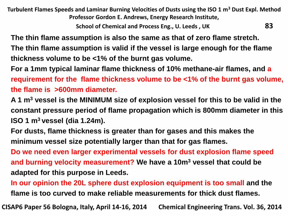
The thin flame assumption is also the same as that of zero flame stretch.
The thin flame assumption is valid if the vessel is large enough for the flame
thickness volume to be <1% of the burnt gas volume.
For a 1mm typical laminar flame thickness of 10% methane-air flames, and a
requirement for the flame thickness volume to be <1% of the burnt gas volume,
the flame is >600mm diameter.
A 1 m3 vessel is the MINIMUM size of explosion vessel for this to be valid in the
constant pressure period of flame propagation which is 800mm diameter in this
ISO 1 m3 vessel (dia 1.24m).
For dusts, flame thickness is greater than for gases and this makes the
minimum vessel size potentially larger than that for gas flames.
Do we need even larger experimental vessels for dust explosion flame speed
and burning velocity measurement? We have a 10m3 vessel that could be
adapted for this purpose in Leeds.
In our opinion the 20L sphere dust explosion equipment is too small and the
flame is too curved to make reliable measurements for thick dust flames.
CISAP6 Paper 56 Bologna, Italy, April 14-16, 2014 Chemical Engineering Trans. Vol. 36, 2014
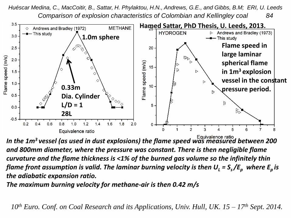
Huéscar Medina, C., MacCoitir, B., Sattar, H. Phylaktou, H.N., Andrews, G.E., and Gibbs, B.M; ERI, U. Leeds
Comparison of explosion characteristics of Colombian and Kellingley coal 84
Hamed Sattar, PhD Thesis, U. Leeds, 2013.
Flame speed inlarge laminarspherical flamein 1m3 explosionvessel in the constantpressure period.
In the 1m3 vessel (as used in dust explosions) the flame speed was measured between 200 and 800mm diameter, where the pressure was constant. There is then negligible flame curvature and the flame thickness is <1% of the burned gas volume so the infinitely thin flame front assumption is valid. The laminar burning velocity is then UL = Ss /Ep where Ep is the adiabatic expansion ratio. The maximum burning velocity for methane-air is then 0.42 m/s
10th Euro. Conf. on Coal Research and its Applications, Univ. Hull, UK. 15 – 17th Sept. 2014.
1.0m sphere
0.33mDia. CylinderL/D = 128L
Turbulent Flames Speeds and Laminar Burning Velocities of Dusts using the ISO 1 m3 Dust Expl. MethodProfessor Gordon E. Andrews, Energy Research Institute,
School of Chemical and Process Eng., U. Leeds , UK 85
CISAP6 Paper 56 Bologna, Italy, April 14-16, 2014 Chemical Engineering Trans. Vol. 36, 2014
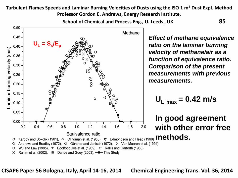
Effect of methane equivalence
ratio on the laminar burning
velocity of methane/air as a
function of equivalence ratio.
Comparison of the present
measurements with previous
measurements.
UL max = 0.42 m/s
In good agreement
with other error free
methods.
UL = Ss/Ep
Turbulent Flames Speeds and Laminar Burning Velocities of Dusts using the ISO 1 m3 Dust Expl. MethodProfessor Gordon E. Andrews, Energy Research Institute,
School of Chemical and Process Eng., U. Leeds , UK 86
CISAP6 Paper 56 Bologna, Italy, April 14-16, 2014 Chemical Engineering Trans. Vol. 36, 2014
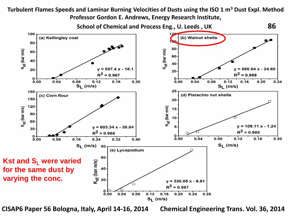
Kst and SL were varied
for the same dust by
varying the conc.
Turbulent Flames Speeds and Laminar Burning Velocities of Dusts using the ISO 1 m3 Dust Expl. MethodProfessor Gordon E. Andrews, Energy Research Institute,
School of Chemical and Process Eng., U. Leeds , UK 87
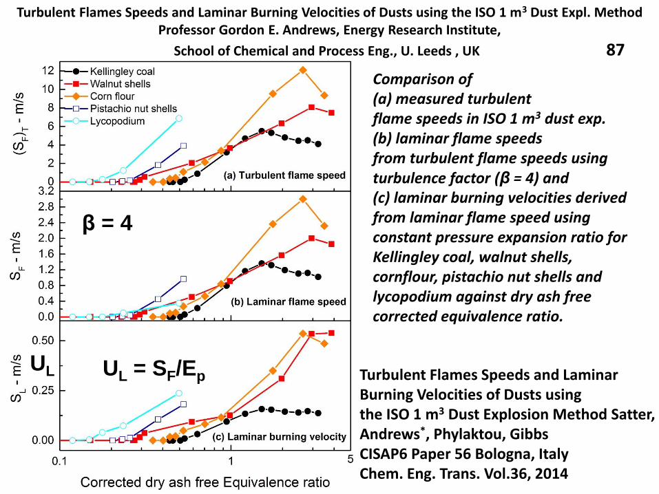
Comparison of (a) measured turbulent flame speeds in ISO 1 m3 dust exp.(b) laminar flame speeds from turbulent flame speeds using turbulence factor (β = 4) and (c) laminar burning velocities derived from laminar flame speed using constant pressure expansion ratio for Kellingley coal, walnut shells, cornflour, pistachio nut shells and lycopodium against dry ash free corrected equivalence ratio.
Turbulent Flames Speeds and Laminar Burning Velocities of Dusts using the ISO 1 m3 Dust Explosion Method Satter, Andrews*, Phylaktou, GibbsCISAP6 Paper 56 Bologna, ItalyChem. Eng. Trans. Vol.36, 2014
β = 4
UL = SF/EpUL
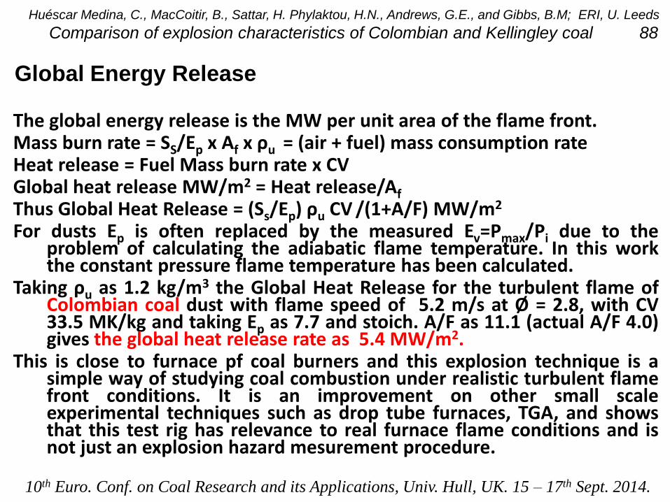
The global energy release is the MW per unit area of the flame front.Mass burn rate = SS/Ep x Af x ρu = (air + fuel) mass consumption rateHeat release = Fuel Mass burn rate x CVGlobal heat release MW/m2 = Heat release/Af
Thus Global Heat Release = (Ss/Ep) ρu CV /(1+A/F) MW/m2
For dusts Ep is often replaced by the measured Ev=Pmax/Pi due to theproblem of calculating the adiabatic flame temperature. In this workthe constant pressure flame temperature has been calculated.
Taking ρu as 1.2 kg/m3 the Global Heat Release for the turbulent flame ofColombian coal dust with flame speed of 5.2 m/s at Ø = 2.8, with CV33.5 MK/kg and taking Ep as 7.7 and stoich. A/F as 11.1 (actual A/F 4.0)gives the global heat release rate as 5.4 MW/m2.
This is close to furnace pf coal burners and this explosion technique is asimple way of studying coal combustion under realistic turbulent flamefront conditions. It is an improvement on other small scaleexperimental techniques such as drop tube furnaces, TGA, and showsthat this test rig has relevance to real furnace flame conditions and isnot just an explosion hazard mesurement procedure.
Global Energy Release
Huéscar Medina, C., MacCoitir, B., Sattar, H. Phylaktou, H.N., Andrews, G.E., and Gibbs, B.M; ERI, U. Leeds
Comparison of explosion characteristics of Colombian and Kellingley coal 88
10th Euro. Conf. on Coal Research and its Applications, Univ. Hull, UK. 15 – 17th Sept. 2014.
Pulverised biomass flame propagation and explosion characteristics: problems and solutions.
Prof. Gordon E. Andrews, Energy Research Institute, SCAPE, Univ. Leeds, UK
Contents
1. Introduction
2. Biomass stoichiometry and variable composition
3. Problems with biomass explosion characterisation.
4. Dust explosion characterisation equipment.
Hartmann for MEC
20L sphere
ISO 1 m3
5. The unburned particle mass in the ISO 1m3
6. Modifications of the ISO 1 m3 vessel for woody biomass.
7. Leeds MEC results for woody biomass
8. Leeds ISO 1 m3 vessel results for biomass (Clara
Huescar Medina will present this in the next lecture).United Kingdom Explosions Liaison Group, UKELG, meeting on Biomass Dust Explosions
University of Leeds, 23.9.2014
Pulverised biomass flame propagation and explosion characteristics with comparison with coal combustion.
Prof. Gordon E. Andrews, Energy Research Institute, SCAPE, Univ. Leeds, UK
Conference on Green Transport, Renewable Energy and Environment (ICGTREE 2014), August 23-24, 2014, Tianjin, China
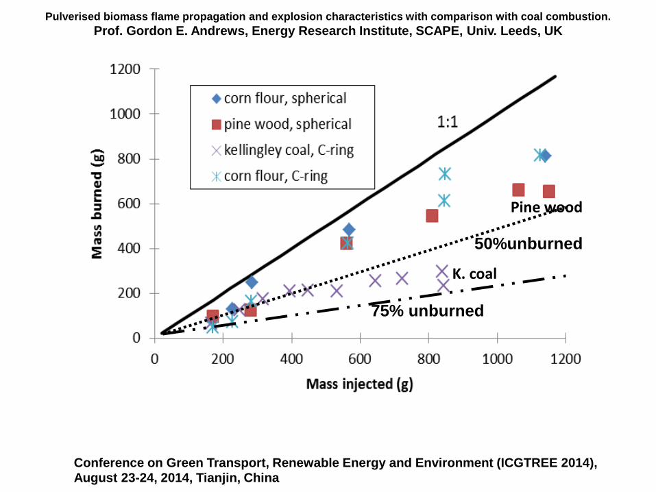
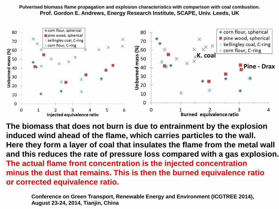
K. coal
Pine wood
50%unburned
75% unburned
Pulverised biomass flame propagation and explosion characteristics with comparison with coal combustion.
Prof. Gordon E. Andrews, Energy Research Institute, SCAPE, Univ. Leeds, UK
Conference on Green Transport, Renewable Energy and Environment (ICGTREE 2014), August 23-24, 2014, Tianjin, China
The biomass that does not burn is due to entrainment by the explosion
induced wind ahead of the flame, which carries particles to the wall.
Here they form a layer of coal that insulates the flame from the metal wall
and this reduces the rate of pressure loss compared with a gas explosion.
The actual flame front concentration is the injected concentration
minus the dust that remains. This is then the burned equivalence ratio
or corrected equivalence ratio.
K. coal
Pine - Drax
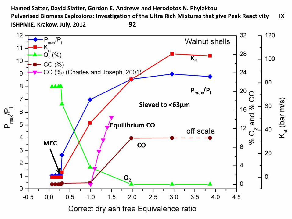
Hamed Satter, David Slatter, Gordon E. Andrews and Herodotos N. PhylaktouPulverised Biomass Explosions: Investigation of the Ultra Rich Mixtures that give Peak Reactivity IX
ISHPMIE, Krakow, July, 2012 92
Sieved to <63μm
MEC
O2
CO
Equilibrium CO
Kst
Pmax/Pi
Pulverised biomass flame propagation and explosion characteristics with comparison with coal combustion.
Prof. Gordon E. Andrews, Energy Research Institute, SCAPE, Univ. Leeds, UK
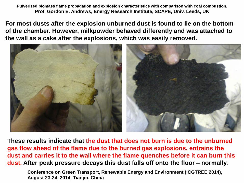
For most dusts after the explosion unburned dust is found to lie on the bottom
of the chamber. However, milkpowder behaved differently and was attached to
the wall as a cake after the explosions, which was easily removed.
Conference on Green Transport, Renewable Energy and Environment (ICGTREE 2014), August 23-24, 2014, Tianjin, China
These results indicate that the dust that does not burn is due to the unburned
gas flow ahead of the flame due to the burned gas explosions, entrains the
dust and carries it to the wall where the flame quenches before it can burn this
dust. After peak pressure decays this dust falls off onto the floor – normally.
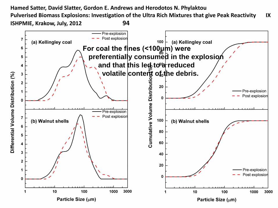
Hamed Satter, David Slatter, Gordon E. Andrews and Herodotos N. PhylaktouPulverised Biomass Explosions: Investigation of the Ultra Rich Mixtures that give Peak Reactivity IX
ISHPMIE, Krakow, July, 2012 94
For coal the fines (<100μm) were
preferentially consumed in the explosion
and that this led to a reduced
volatile content of the debris.
Pulverised biomass flame propagation and explosion characteristics: problems and solutions.
Prof. Gordon E. Andrews, Energy Research Institute, SCAPE, Univ. Leeds, UK
Contents
1. Introduction
2. Biomass stoichiometry and variable composition
3. Problems with biomass explosion characterisation.
4. Dust explosion characterisation equipment.
Hartmann for MEC
20L sphere
ISO 1 m3
5. The unburned particle mass in the ISO 1m3
6. Modifications of the ISO 1 m3 vessel for woody biomass.
7. Leeds MEC results for woody biomass
8. Leeds ISO 1 m3 vessel results for biomass (Clara
Huescar Medina will present this in the next lecture).United Kingdom Explosions Liaison Group, UKELG, meeting on Biomass Dust Explosions
University of Leeds, 23.9.2014
Pulverised biomass flame propagation and explosion characteristics: problems and solutions.
Prof. Gordon E. Andrews, Energy Research Institute, SCAPE, Univ. Leeds, UK
The problem with the 20L sphere and 1 m3 dust explosion
vessels is that they will not operate with woody biomass,
even if they are milled to <63µm. We have no 20L sphere
experience but can certify that the standard C ring will not
pass any biomass that is fibrous. This is why we started our
biomass work with nut shell biomass, as these are brittle
and will pass through the standard injection system.
New injection systems are required and they must be cross
referenced to the standard system by calibration with a
dust of known Kst. We use cornflour as our reference dust.
We have calibrated various injection system for biomass
and have concluded that for coarse fibrous biomass it is
essential to place the biomass in the explosion vessel and
disperse it with the usual external compressed air source.
United Kingdom Explosions Liaison Group, UKELG, meeting on Biomass Dust ExplosionsUniversity of Leeds, 23.9.2014
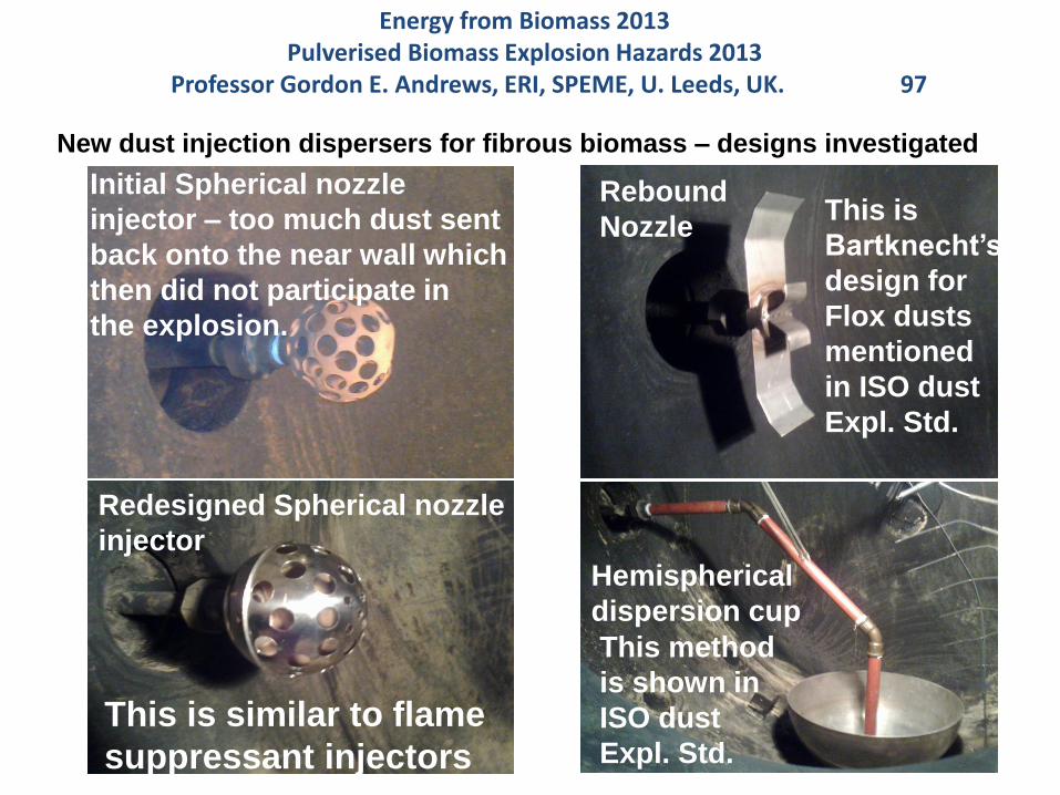
Initial Spherical nozzle
injector – too much dust sent
back onto the near wall which
then did not participate in
the explosion.
Redesigned Spherical nozzle
injector
Hemispherical
dispersion cup
Rebound
Nozzle
New dust injection dispersers for fibrous biomass – designs investigated
This is similar to flame
suppressant injectors
This is
Bartknecht’s
design for
Flox dusts
mentioned
in ISO dust
Expl. Std.
This method
is shown in
ISO dust
Expl. Std.
Energy from Biomass 2013Pulverised Biomass Explosion Hazards 2013
Professor Gordon E. Andrews, ERI, SPEME, U. Leeds, UK. 97
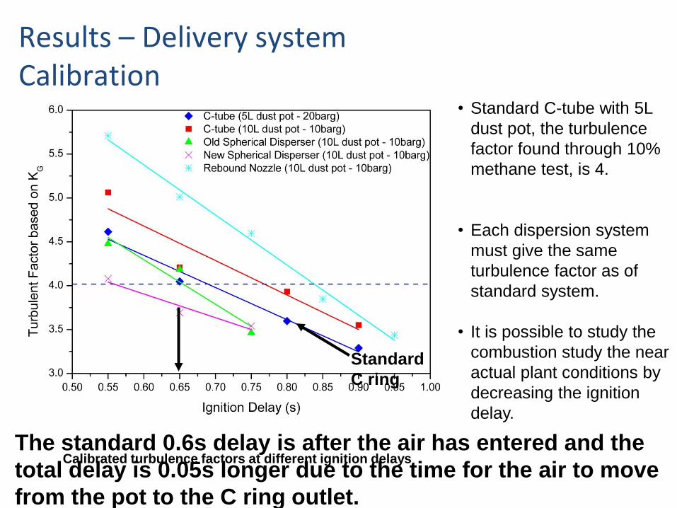
Results – Delivery system Calibration
Calibrated turbulence factors at different ignition delays
• Standard C-tube with 5L
dust pot, the turbulence
factor found through 10%
methane test, is 4.
• Each dispersion system
must give the same
turbulence factor as of
standard system.
• It is possible to study the
combustion study the near
actual plant conditions by
decreasing the ignition
delay.
Standard
C ring
The standard 0.6s delay is after the air has entered and the
total delay is 0.05s longer due to the time for the air to move
from the pot to the C ring outlet.
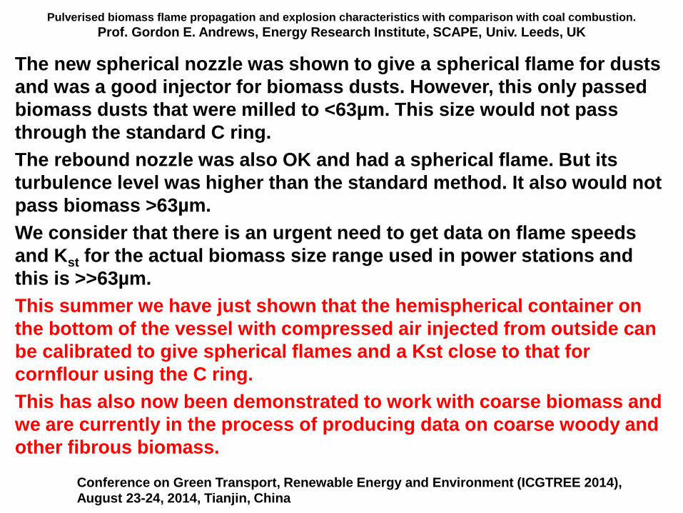
Pulverised biomass flame propagation and explosion characteristics with comparison with coal combustion.
Prof. Gordon E. Andrews, Energy Research Institute, SCAPE, Univ. Leeds, UK
The new spherical nozzle was shown to give a spherical flame for dusts
and was a good injector for biomass dusts. However, this only passed
biomass dusts that were milled to <63µm. This size would not pass
through the standard C ring.
The rebound nozzle was also OK and had a spherical flame. But its
turbulence level was higher than the standard method. It also would not
pass biomass >63µm.
We consider that there is an urgent need to get data on flame speeds
and Kst for the actual biomass size range used in power stations and
this is >>63µm.
This summer we have just shown that the hemispherical container on
the bottom of the vessel with compressed air injected from outside can
be calibrated to give spherical flames and a Kst close to that for
cornflour using the C ring.
This has also now been demonstrated to work with coarse biomass and
we are currently in the process of producing data on coarse woody and
other fibrous biomass.
Conference on Green Transport, Renewable Energy and Environment (ICGTREE 2014), August 23-24, 2014, Tianjin, China
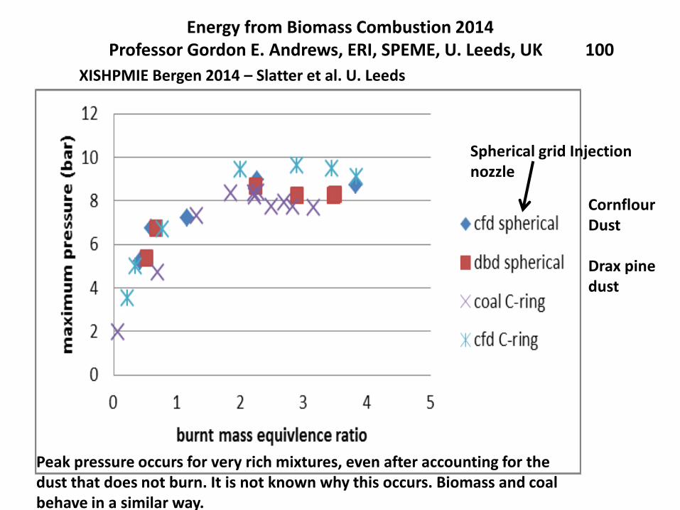
Energy from Biomass Combustion 2014Professor Gordon E. Andrews, ERI, SPEME, U. Leeds, UK 100
XISHPMIE Bergen 2014 – Slatter et al. U. Leeds
CornflourDust
Drax pinedust
Spherical grid Injectionnozzle
Peak pressure occurs for very rich mixtures, even after accounting for thedust that does not burn. It is not known why this occurs. Biomass and coalbehave in a similar way.
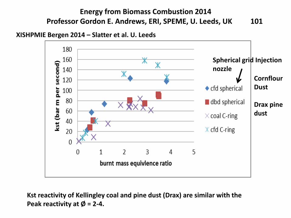
Energy from Biomass Combustion 2014Professor Gordon E. Andrews, ERI, SPEME, U. Leeds, UK 101
XISHPMIE Bergen 2014 – Slatter et al. U. Leeds
Spherical grid Injectionnozzle
CornflourDust
Drax pinedust
Kst reactivity of Kellingley coal and pine dust (Drax) are similar with thePeak reactivity at Ø = 2-4.
Pulverised biomass flame propagation and explosion characteristics: problems and solutions.
Prof. Gordon E. Andrews, Energy Research Institute, SCAPE, Univ. Leeds, UK
Contents
1. Introduction
2. Some characteristics of biomass
3. Biomass stoichiometry and variable composition
4. Problems with biomass explosion characterisation.
5. Dust explosion characterisation equipment.
Hartmann for MEC
20L sphere
ISO 1 m3
5. Modifications of the ISO 1 m3 vessel for woody biomass.
6. Leeds MEC results for woody biomass
7. Leeds ISO 1 m3 vessel results for biomass (Clara
Huescar Medina will present this in the next lecture).United Kingdom Explosions Liaison Group, UKELG, meeting on Biomass Dust Explosions
University of Leeds, 23.9.2014
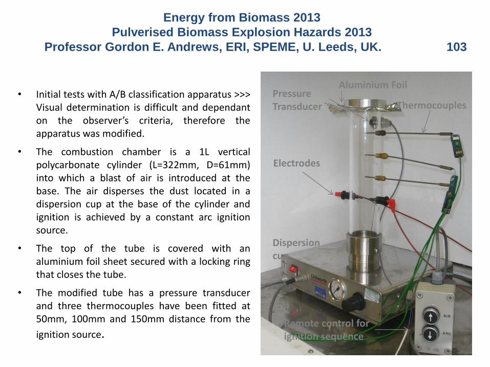
• Initial tests with A/B classification apparatus >>>Visual determination is difficult and dependanton the observer’s criteria, therefore theapparatus was modified.
• The combustion chamber is a 1L verticalpolycarbonate cylinder (L=322mm, D=61mm)into which a blast of air is introduced at thebase. The air disperses the dust located in adispersion cup at the base of the cylinder andignition is achieved by a constant arc ignitionsource.
• The top of the tube is covered with analuminium foil sheet secured with a locking ringthat closes the tube.
• The modified tube has a pressure transducerand three thermocouples have been fitted at50mm, 100mm and 150mm distance from the
ignition source.
Electrodes
Dispersion cup
Thermocouples
Remote control for ignition sequence
Pressure Transducer
Aluminium Foil
Energy from Biomass 2013
Pulverised Biomass Explosion Hazards 2013
Professor Gordon E. Andrews, ERI, SPEME, U. Leeds, UK. 103
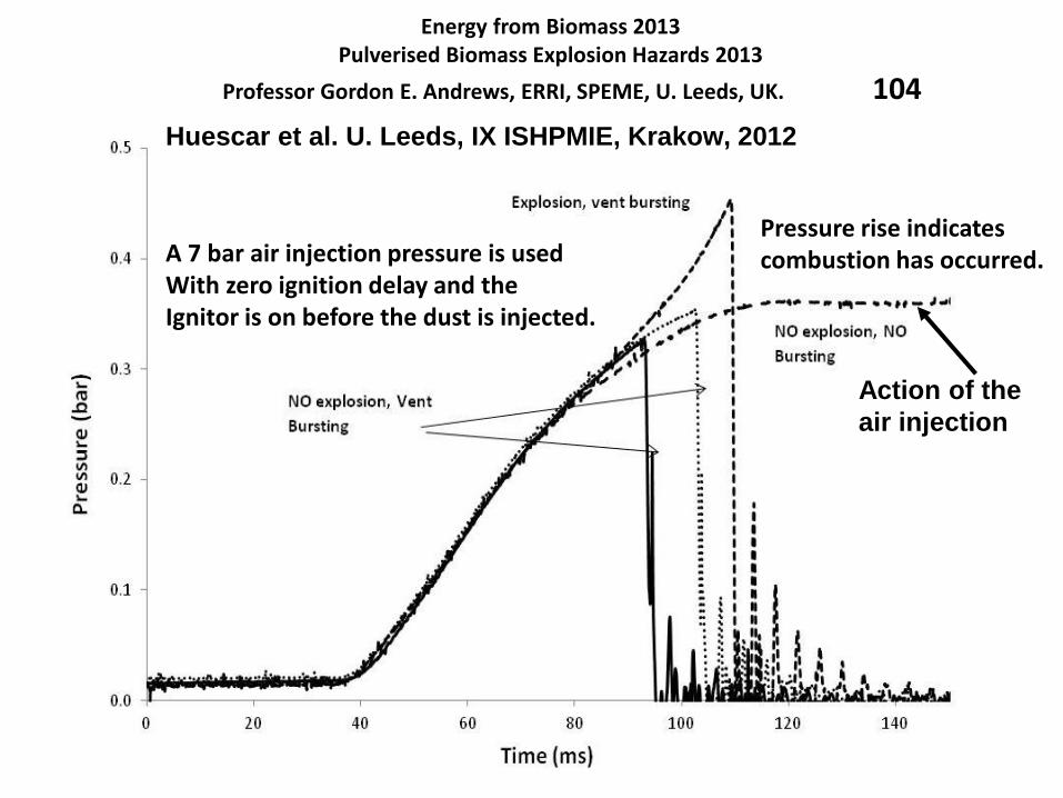
Energy from Biomass 2013Pulverised Biomass Explosion Hazards 2013
Professor Gordon E. Andrews, ERRI, SPEME, U. Leeds, UK. 104
Huescar et al. U. Leeds, IX ISHPMIE, Krakow, 2012
Action of the
air injection
A 7 bar air injection pressure is usedWith zero ignition delay and theIgnitor is on before the dust is injected.
Pressure rise indicatescombustion has occurred.
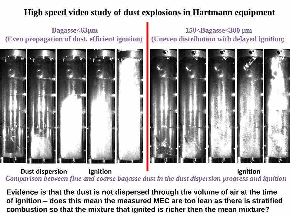
High speed video study of dust explosions in Hartmann equipment
Bagasse<63µm
(Even propagation of dust, efficient ignition)
150<Bagasse<300 µm
(Uneven distribution with delayed ignition)
Comparison between fine and coarse bagasse dust in the dust dispersion progress and ignition Ignition IgnitionDust dispersion
Evidence is that the dust is not dispersed through the volume of air at the time
of ignition – does this mean the measured MEC are too lean as there is stratified
combustion so that the mixture that ignited is richer then the mean mixture?
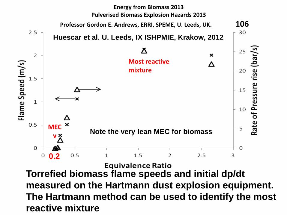
Energy from Biomass 2013Pulverised Biomass Explosion Hazards 2013
Professor Gordon E. Andrews, ERRI, SPEME, U. Leeds, UK. 106
Torrefied biomass flame speeds and initial dp/dt
measured on the Hartmann dust explosion equipment.
The Hartmann method can be used to identify the most
reactive mixture
Huescar et al. U. Leeds, IX ISHPMIE, Krakow, 2012
MECv
Most reactivemixture
0.2
Note the very lean MEC for biomass
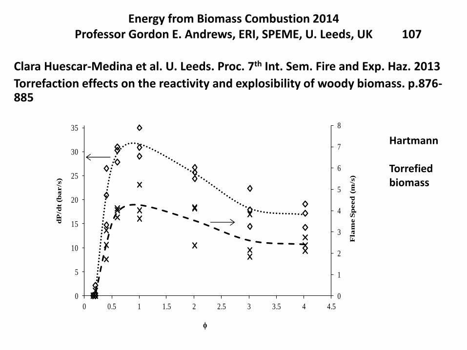
Energy from Biomass Combustion 2014Professor Gordon E. Andrews, ERI, SPEME, U. Leeds, UK 107
Clara Huescar-Medina et al. U. Leeds. Proc. 7th Int. Sem. Fire and Exp. Haz. 2013
Torrefaction effects on the reactivity and explosibility of woody biomass. p.876-885
0
1
2
3
4
5
6
7
8
0
5
10
15
20
25
30
35
0 0.5 1 1.5 2 2.5 3 3.5 4 4.5
Fla
me S
peed
(m
/s)
dP
/dt
(ba
r/s
)
ϕ
Hartmann
Torrefiedbiomass
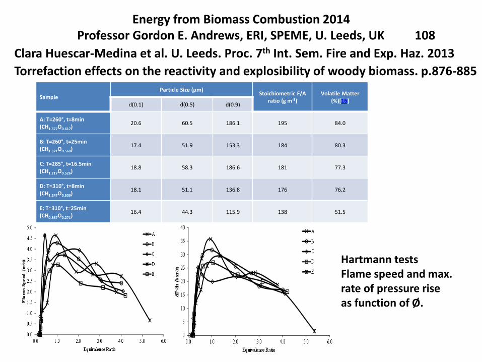
Energy from Biomass Combustion 2014Professor Gordon E. Andrews, ERI, SPEME, U. Leeds, UK 108
Clara Huescar-Medina et al. U. Leeds. Proc. 7th Int. Sem. Fire and Exp. Haz. 2013
Torrefaction effects on the reactivity and explosibility of woody biomass. p.876-885
SampleParticle Size (μm)
Stoichiometric F/A ratio (g m-3)
Volatile Matter (%)[16]
d(0.1) d(0.5) d(0.9)
A: T=260°, t=8min (CH1.377O0.617)
20.6 60.5 186.1 195 84.0
B: T=260°, t=25min (CH1.321O0.560)
17.4 51.9 153.3 184 80.3
C: T=285°, t=16.5min (CH1.217O0.526)
18.8 58.3 186.6 181 77.3
D: T=310°, t=8min (CH1.247O0.509)
18.1 51.1 136.8 176 76.2
E: T=310°, t=25min (CH0.867O0.271)
16.4 44.3 115.9 138 51.5
Hartmann testsFlame speed and max.rate of pressure riseas function of Ø.
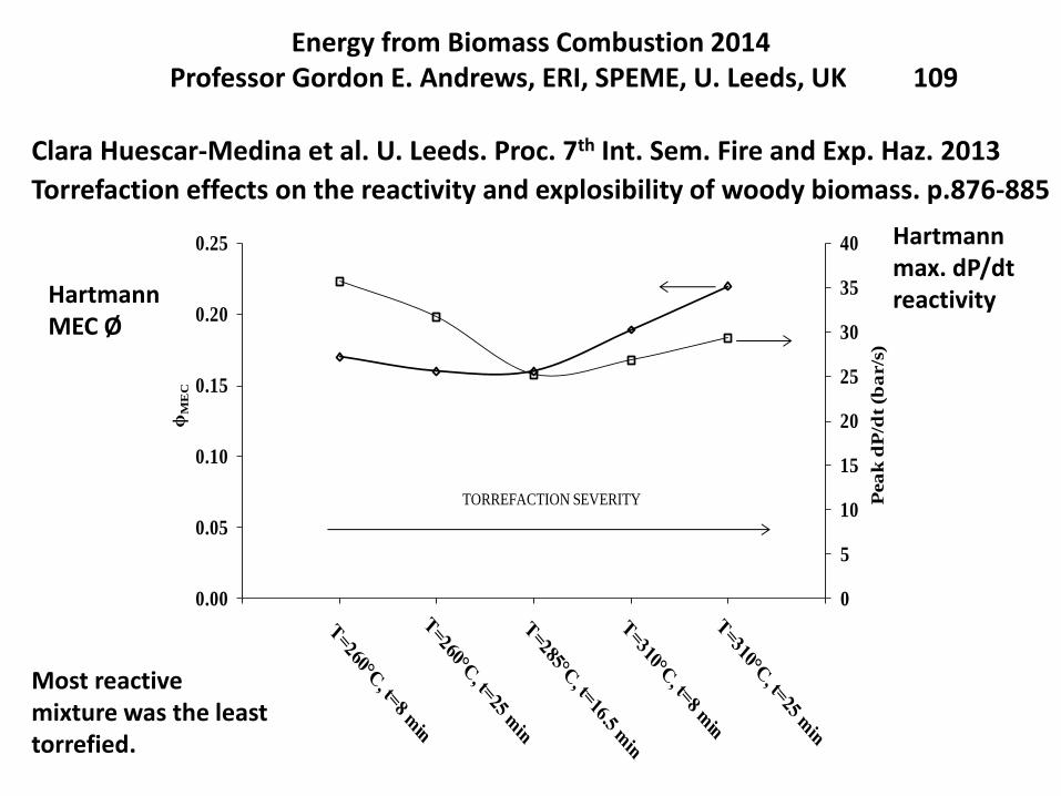
Energy from Biomass Combustion 2014Professor Gordon E. Andrews, ERI, SPEME, U. Leeds, UK 109
Clara Huescar-Medina et al. U. Leeds. Proc. 7th Int. Sem. Fire and Exp. Haz. 2013
Torrefaction effects on the reactivity and explosibility of woody biomass. p.876-885
0
5
10
15
20
25
30
35
40
0.00
0.05
0.10
0.15
0.20
0.25
0 1 2 3 4 5 6
Pea
k d
P/d
t (b
ar/s
)
ϕM
EC
TORREFACTION SEVERITY
HartmannMEC Ø
Hartmannmax. dP/dtreactivity
Most reactivemixture was the leasttorrefied.
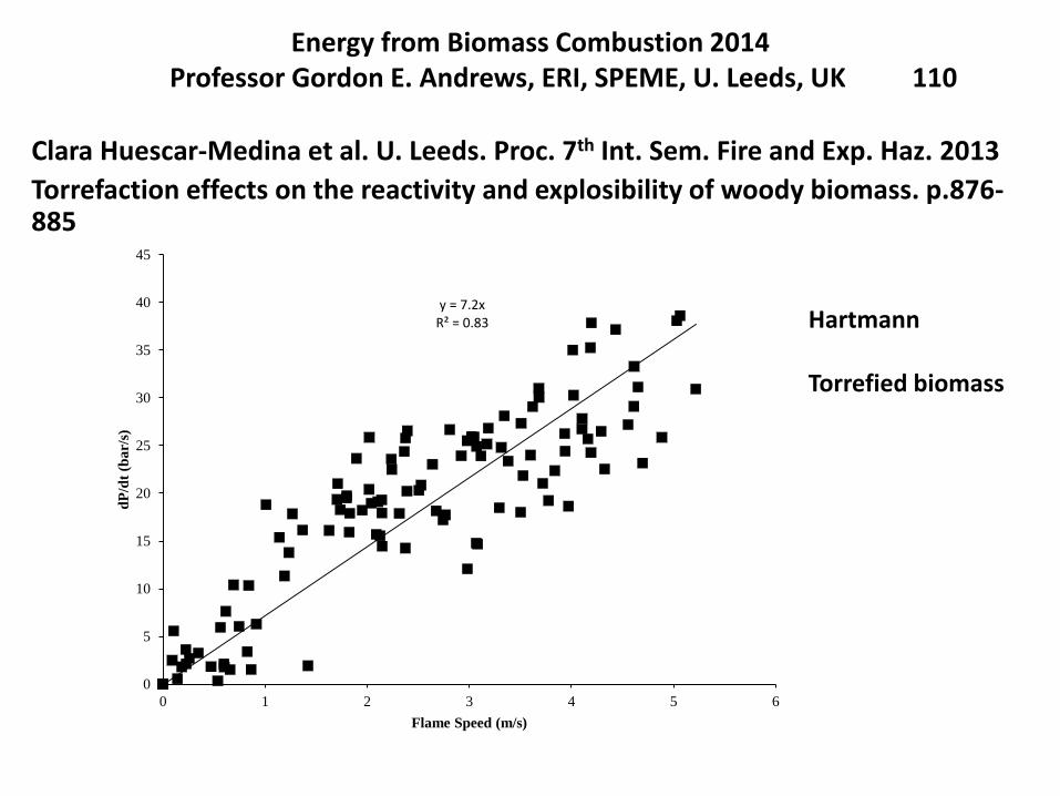
Energy from Biomass Combustion 2014Professor Gordon E. Andrews, ERI, SPEME, U. Leeds, UK 110
Clara Huescar-Medina et al. U. Leeds. Proc. 7th Int. Sem. Fire and Exp. Haz. 2013
Torrefaction effects on the reactivity and explosibility of woody biomass. p.876-885
y = 7.2xR² = 0.83
0
5
10
15
20
25
30
35
40
45
0 1 2 3 4 5 6
dP
/dt
(ba
r/s)
Flame Speed (m/s)
Hartmann
Torrefied biomass
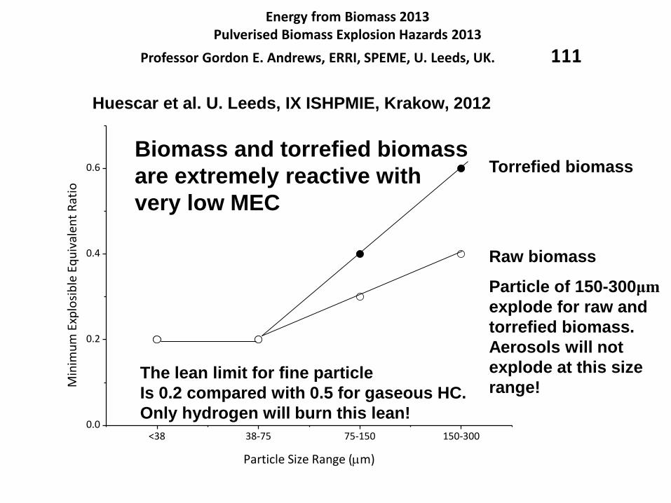
Energy from Biomass 2013Pulverised Biomass Explosion Hazards 2013
Professor Gordon E. Andrews, ERRI, SPEME, U. Leeds, UK. 111
<38 38-75 75-150 150-3000.0
0.2
0.4
0.6
Min
imu
m E
xplo
sib
le E
qu
ival
ent
Rat
io
Particle Size Range (m)
Torrefied biomass
Raw biomass
Huescar et al. U. Leeds, IX ISHPMIE, Krakow, 2012
Particle of 150-300μm
explode for raw and
torrefied biomass.
Aerosols will not
explode at this size
range!The lean limit for fine particle
Is 0.2 compared with 0.5 for gaseous HC.
Only hydrogen will burn this lean!
Biomass and torrefied biomass
are extremely reactive with
very low MEC
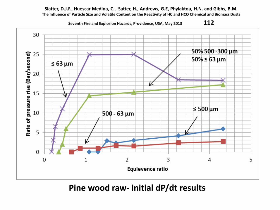
Slatter, D.J.F., Huescar Medina, C., Satter, H., Andrews, G.E, Phylaktou, H.N. and Gibbs, B.M.The Influence of Particle Size and Volatile Content on the Reactivity of HC and HCO Chemical and Biomass Dusts
Seventh Fire and Explosion Hazards, Providence, USA, May 2013 112
Pine wood raw- initial dP/dt results
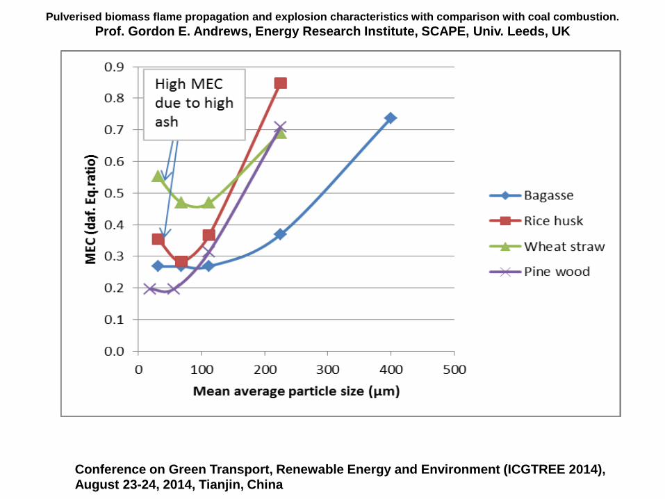
Pulverised biomass flame propagation and explosion characteristics with comparison with coal combustion.
Prof. Gordon E. Andrews, Energy Research Institute, SCAPE, Univ. Leeds, UK
Conference on Green Transport, Renewable Energy and Environment (ICGTREE 2014), August 23-24, 2014, Tianjin, China
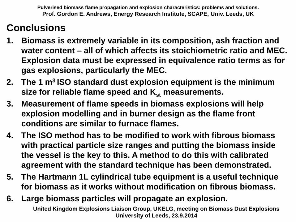
Pulverised biomass flame propagation and explosion characteristics: problems and solutions.
Prof. Gordon E. Andrews, Energy Research Institute, SCAPE, Univ. Leeds, UK
Conclusions
1. Biomass is extremely variable in its composition, ash fraction and
water content – all of which affects its stoichiometric ratio and MEC.
Explosion data must be expressed in equivalence ratio terms as for
gas explosions, particularly the MEC.
2. The 1 m3 ISO standard dust explosion equipment is the minimum
size for reliable flame speed and Kst measurements.
3. Measurement of flame speeds in biomass explosions will help
explosion modelling and in burner design as the flame front
conditions are similar to furnace flames.
4. The ISO method has to be modified to work with fibrous biomass
with practical particle size ranges and putting the biomass inside
the vessel is the key to this. A method to do this with calibrated
agreement with the standard technique has been demonstrated.
5. The Hartmann 1L cylindrical tube equipment is a useful technique
for biomass as it works without modification on fibrous biomass.
6. Large biomass particles will propagate an explosion.United Kingdom Explosions Liaison Group, UKELG, meeting on Biomass Dust Explosions
University of Leeds, 23.9.2014
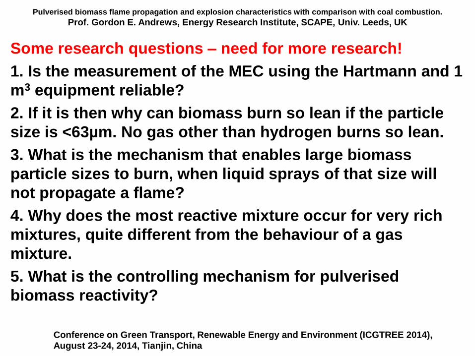
Pulverised biomass flame propagation and explosion characteristics with comparison with coal combustion.
Prof. Gordon E. Andrews, Energy Research Institute, SCAPE, Univ. Leeds, UK
Some research questions – need for more research!
1. Is the measurement of the MEC using the Hartmann and 1
m3 equipment reliable?
2. If it is then why can biomass burn so lean if the particle
size is <63µm. No gas other than hydrogen burns so lean.
3. What is the mechanism that enables large biomass
particle sizes to burn, when liquid sprays of that size will
not propagate a flame?
4. Why does the most reactive mixture occur for very rich
mixtures, quite different from the behaviour of a gas
mixture.
5. What is the controlling mechanism for pulverised
biomass reactivity?
Conference on Green Transport, Renewable Energy and Environment (ICGTREE 2014), August 23-24, 2014, Tianjin, China
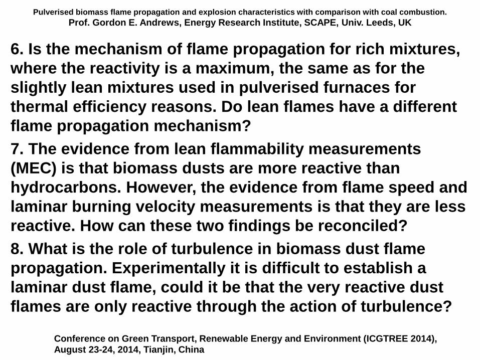
Pulverised biomass flame propagation and explosion characteristics with comparison with coal combustion.
Prof. Gordon E. Andrews, Energy Research Institute, SCAPE, Univ. Leeds, UK
6. Is the mechanism of flame propagation for rich mixtures,
where the reactivity is a maximum, the same as for the
slightly lean mixtures used in pulverised furnaces for
thermal efficiency reasons. Do lean flames have a different
flame propagation mechanism?
7. The evidence from lean flammability measurements
(MEC) is that biomass dusts are more reactive than
hydrocarbons. However, the evidence from flame speed and
laminar burning velocity measurements is that they are less
reactive. How can these two findings be reconciled?
8. What is the role of turbulence in biomass dust flame
propagation. Experimentally it is difficult to establish a
laminar dust flame, could it be that the very reactive dust
flames are only reactive through the action of turbulence?
Conference on Green Transport, Renewable Energy and Environment (ICGTREE 2014), August 23-24, 2014, Tianjin, China
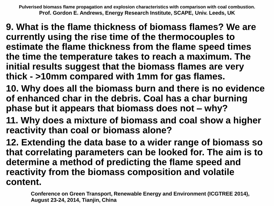
Pulverised biomass flame propagation and explosion characteristics with comparison with coal combustion.
Prof. Gordon E. Andrews, Energy Research Institute, SCAPE, Univ. Leeds, UK
9. What is the flame thickness of biomass flames? We are currently using the rise time of the thermocouples to estimate the flame thickness from the flame speed times the time the temperature takes to reach a maximum. The initial results suggest that the biomass flames are very thick - >10mm compared with 1mm for gas flames.
10. Why does all the biomass burn and there is no evidence of enhanced char in the debris. Coal has a char burning phase but it appears that biomass does not – why?
11. Why does a mixture of biomass and coal show a higher reactivity than coal or biomass alone?
12. Extending the data base to a wider range of biomass so that correlating parameters can be looked for. The aim is to determine a method of predicting the flame speed and reactivity from the biomass composition and volatile content.
Conference on Green Transport, Renewable Energy and Environment (ICGTREE 2014), August 23-24, 2014, Tianjin, China
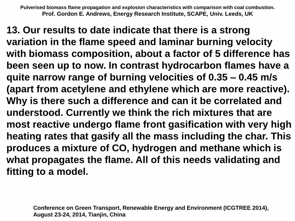
Pulverised biomass flame propagation and explosion characteristics with comparison with coal combustion.
Prof. Gordon E. Andrews, Energy Research Institute, SCAPE, Univ. Leeds, UK
13. Our results to date indicate that there is a strong
variation in the flame speed and laminar burning velocity
with biomass composition, about a factor of 5 difference has
been seen up to now. In contrast hydrocarbon flames have a
quite narrow range of burning velocities of 0.35 – 0.45 m/s
(apart from acetylene and ethylene which are more reactive).
Why is there such a difference and can it be correlated and
understood. Currently we think the rich mixtures that are
most reactive undergo flame front gasification with very high
heating rates that gasify all the mass including the char. This
produces a mixture of CO, hydrogen and methane which is
what propagates the flame. All of this needs validating and
fitting to a model.
Conference on Green Transport, Renewable Energy and Environment (ICGTREE 2014), August 23-24, 2014, Tianjin, China
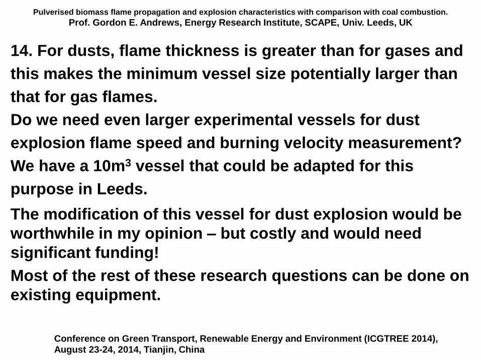
Pulverised biomass flame propagation and explosion characteristics with comparison with coal combustion.
Prof. Gordon E. Andrews, Energy Research Institute, SCAPE, Univ. Leeds, UK
14. For dusts, flame thickness is greater than for gases and
this makes the minimum vessel size potentially larger than
that for gas flames.
Do we need even larger experimental vessels for dust
explosion flame speed and burning velocity measurement?
We have a 10m3 vessel that could be adapted for this
purpose in Leeds.
The modification of this vessel for dust explosion would be
worthwhile in my opinion – but costly and would need
significant funding!
Most of the rest of these research questions can be done on
existing equipment.
Conference on Green Transport, Renewable Energy and Environment (ICGTREE 2014), August 23-24, 2014, Tianjin, China
Pulverised biomass flame propagation and explosion characteristics with comparison with coal combustion.
Prof. Gordon E. Andrews, Energy Research Institute, SCAPE, Univ. Leeds, UK
15. What is the influence of explosion vessel size on the
flame propagation in biomass dust clouds. Do biomass dust
flames have a self acceleration mechanism similar to gas
flames.
Some biomass stores are being built larger that current
knowledge on biomass or gas explosions. Can existing
design guides be applied to volumes much larger than that
they were validated for.
Is there a need for large scale dust explosion research?
Conference on Green Transport, Renewable Energy and Environment (ICGTREE 2014), August 23-24, 2014, Tianjin, China
Pulverised biomass flame propagation and explosion characteristics with comparison with coal combustion.
Prof. Gordon E. Andrews, Energy Research Institute, SCAPE, Univ. Leeds, UK
16. Why does methanol, which has the same elemental
composition as wood, have lean limits in terms of
equivalence ratio closer to that of hydrocarbons than wood?
17. Liquid aerosols or sprays.
The question about methanol leads to the more general area
of liquid sprays. There is currently no accepted experimental
method to test for flame propagation in aerosols. We think
that the equipment used for dusts could be adapted for
liquids, particularly the Hartmann equipment for the lean
limits and the 1 m3 for flame propagation. This would involve
putting the liquid of known mass inside the equipment and
then blasting air at it, which will atomise and disperse the
liquid.
Conference on Green Transport, Renewable Energy and Environment (ICGTREE 2014), August 23-24, 2014, Tianjin, China
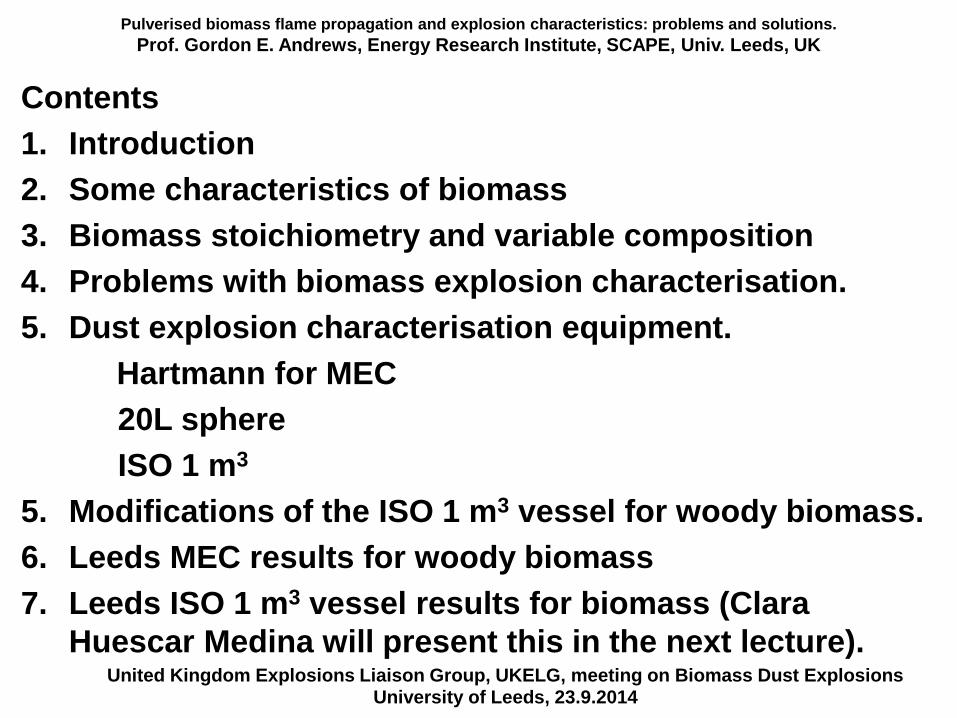
Pulverised biomass flame propagation and explosion characteristics: problems and solutions.
Prof. Gordon E. Andrews, Energy Research Institute, SCAPE, Univ. Leeds, UK
Contents
1. Introduction
2. Some characteristics of biomass
3. Biomass stoichiometry and variable composition
4. Problems with biomass explosion characterisation.
5. Dust explosion characterisation equipment.
Hartmann for MEC
20L sphere
ISO 1 m3
5. Modifications of the ISO 1 m3 vessel for woody biomass.
6. Leeds MEC results for woody biomass
7. Leeds ISO 1 m3 vessel results for biomass (Clara
Huescar Medina will present this in the next lecture).United Kingdom Explosions Liaison Group, UKELG, meeting on Biomass Dust Explosions
University of Leeds, 23.9.2014
Pulverised biomass flame propagation and explosion characteristics: problems and solutions.
Prof. Gordon E. Andrews, Energy Research Institute, SCAPE, Univ. Leeds, UK
United Kingdom Explosions Liaison Group, UKELG, meeting on Biomass Dust ExplosionsUniversity of Leeds, 23.9.2014