Embed Size (px)
Citation preview

VERTICAL ALIGNMENTS
AND PROFILES
January 2006
NEW YORK STATE DEPARTMENT OF TRANSPORTATION

Table of Contents
Chapter 1 - Vertical Alignments Create a New File Page 1- 4 Open a Geometry Project Page 1- 4 Create a Vertical Alignment from Surface Page 1- 4 Create a Profile Page 1-10 Modifying the Vertical Alignment Page 1-20 Modifying Alignments in ASCII Page 1-22 Create New Vertical Alignments With
Vertical Curve Set Page 1-30 Copy Geometry Page 1-30 Review Vertical Alignment Page 1-38 Dynamic Controls Page 1-42 Vertical Alignments by Key-In Page 1-42 Vertical Alignments by Vertical Element Tools Page 1-44 Chapter 2 - Profiles Annotating Profiles Page 2- 4 Preparing Profiles for Contract Plans Page 2-12
Course Prerequisites The following is a list of requirements that must be met by a student before entering class:
√ MicroStation experience
√ A basic understanding of the InRoads environment
√ A basic knowledge of the components of vertical alignments
Introduction
In this class we will learn multiple ways of creating a vertical alignments and annotating them. The alignments will be used to create profiles. Design criteria for creating vertical alignments will not be covered in this class.


Vertical Alignments
Chapter 1 - Page Number 2
Chapter 1 Vertical Alignments
Introduction...
This chapter will demonstrate the multiple tools available to create a vertical alignment.

D2 Vertical Alignments and Profiles
Chapter 1 - Page Number 3
Type AZ=0, tag view and turn depth lock on. Bring up the locks toolbar, if it’s not up already. Turn on Write, Station and Report locks. Pencil, or Pen with Delete Ink may be used. Using Pen mode without Delete Ink activated will allow multiple graphical displays.
* A Geometry Project can also be created by going to File > New or type Ctrl + N
Vertical Alignments
Chapter 1 - Page Number 4
Vertical alignments are either chorded (PVI’s at an interval with no vertical curves), or created with tangents and vertical curves.
Vertical alignments can be created utilizing many different methods. It is very important that the designer know what the alignments will be used for in construction as well as design before alignment creation, as the accuracy and precision of the model can be affected by which method is chosen.
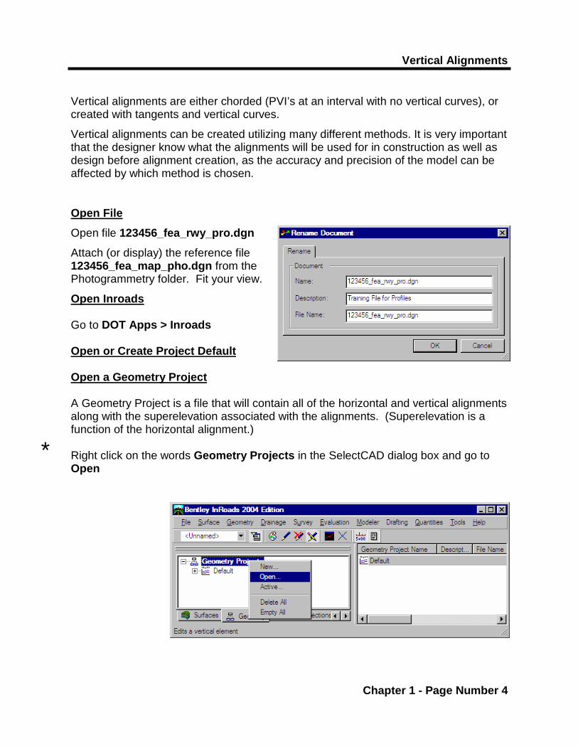
Open File
Open file 123456_fea_rwy_pro.dgn
Attach (or display) the reference file 123456_fea_map_pho.dgn from the Photogrammetry folder. Fit your view.
Open Inroads Go to DOT Apps > Inroads Open or Create Project Default Open a Geometry Project A Geometry Project is a file that will contain all of the horizontal and vertical alignments along with the superelevation associated with the alignments. (Superelevation is a function of the horizontal alignment.) Right click on the words Geometry Projects in the SelectCAD dialog box and go to Open
*

D2 Vertical Alignments and Profiles
Chapter 1 - Page Number 5
Use the toolbars. Under Tools > Customize > , bring up the View Geometry, Verti-cal Curve Set, Vertical Element, and Profile toolbars *
Vertical Alignments
Chapter 1 - Page Number 6
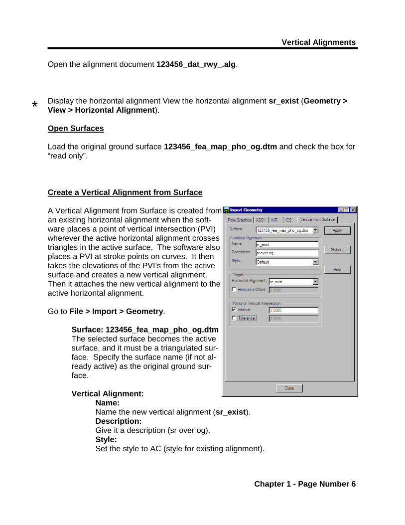
Open the alignment document 123456_dat_rwy_.alg. Display the horizontal alignment View the horizontal alignment sr_exist (Geometry > View > Horizontal Alignment). Open Surfaces Load the original ground surface 123456_fea_map_pho_og.dtm and check the box for “read only”. Create a Vertical Alignment from Surface A Vertical Alignment from Surface is created from an existing horizontal alignment when the soft-ware places a point of vertical intersection (PVI) wherever the active horizontal alignment crosses triangles in the active surface. The software also places a PVI at stroke points on curves. It then takes the elevations of the PVI’s from the active surface and creates a new vertical alignment. Then it attaches the new vertical alignment to the active horizontal alignment. Go to File > Import > Geometry. Surface: 123456_fea_map_pho_og.dtm
The selected surface becomes the active surface, and it must be a triangulated sur-face. Specify the surface name (if not al-ready active) as the original ground sur-face.
Vertical Alignment: Name:
Name the new vertical alignment (sr_exist). Description:
Give it a description (sr over og). Style: Set the style to AC (style for existing alignment).
*

D2 Vertical Alignments and Profiles
Chapter 1 - Page Number 7
Vertical Alignments
Chapter 1 - Page Number 8
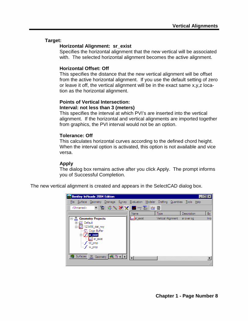
Target: Horizontal Alignment: sr_exist Specifies the horizontal alignment that the new vertical will be associated with. The selected horizontal alignment becomes the active alignment. Horizontal Offset: Off This specifies the distance that the new vertical alignment will be offset from the active horizontal alignment. If you use the default setting of zero or leave it off, the vertical alignment will be in the exact same x,y,z loca-tion as the horizontal alignment. Points of Vertical Intersection: Interval: not less than 3 (meters) This specifies the interval at which PVI’s are inserted into the vertical alignment. If the horizontal and vertical alignments are imported together from graphics, the PVI interval would not be an option. Tolerance: Off This calculates horizontal curves according to the defined chord height. When the interval option is activated, this option is not available and vice versa. Apply The dialog box remains active after you click Apply. The prompt informs you of Successful Completion.
The new vertical alignment is created and appears in the SelectCAD dialog box.

D2 Vertical Alignments and Profiles
Chapter 1 - Page Number 9
Vertical Alignments
Chapter 1 - Page Number 10
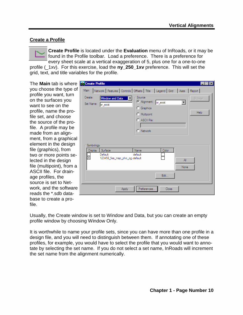
Create a Profile Create Profile is located under the Evaluation menu of InRoads, or it may be found in the Profile toolbar. Load a preference. There is a preference for every sheet scale at a vertical exaggeration of 5, plus one for a one-to-one
profile (_1xv). For this exercise, load the ny_250_1xv preference. This will set the grid, text, and title variables for the profile. The Main tab is where you choose the type of profile you want, turn on the surfaces you want to see on the profile, name the pro-file set, and choose the source of the pro-file. A profile may be made from an align-ment, from a graphical element in the design file (graphics), from two or more points se-lected in the design file (multipoint), from a ASCII file. For drain-age profiles, the source is set to Net-work, and the software reads the *.sdb data-base to create a pro-file. Usually, the Create window is set to Window and Data, but you can create an empty profile window by choosing Window Only. It is worthwhile to name your profile sets, since you can have more than one profile in a design file, and you will need to distinguish between them. If annotating one of these profiles, for example, you would have to select the profile that you would want to anno-tate by selecting the set name. If you do not select a set name, InRoads will increment the set name from the alignment numerically.
D2 Vertical Alignments and Profiles
Chapter 1 - Page Number 11
* Alignments should be created to station South to North and West to East, for main line roads, and from the mainline out for side roads.
Vertical Alignments
Chapter 1 - Page Number 12
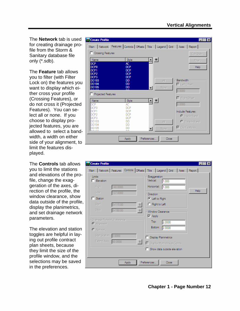
The Network tab is used for creating drainage pro-file from the Storm & Sanitary database file only (*.sdb). The Feature tab allows you to filter (with Filter Lock on) the features you want to display which ei-ther cross your profile (Crossing Features), or do not cross it (Projected Features). You can se-lect all or none. If you choose to display pro-jected features, you are allowed to select a band-width, a width on either side of your alignment, to limit the features dis-played. The Controls tab allows you to limit the stations and elevations of the pro-file, change the exag-geration of the axes, di-rection of the profile, the window clearance, show data outside of the profile, display the planimetrics, and set drainage network parameters. The elevation and station toggles are helpful in lay-ing out profile contract plan sheets, because they limit the size of the profile window, and the selections may be saved in the preferences.

D2 Vertical Alignments and Profiles
Chapter 1 - Page Number 13
Vertical Alignments
Chapter 1 - Page Number 14
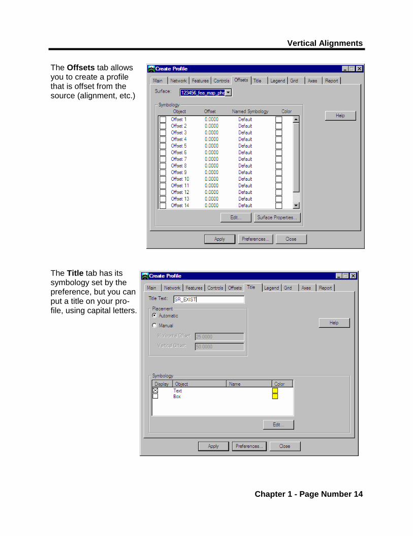
The Offsets tab allows you to create a profile that is offset from the source (alignment, etc.) The Title tab has its symbology set by the preference, but you can put a title on your pro-file, using capital letters.
D2 Vertical Alignments and Profiles
Chapter 1 - Page Number 15
A profile is a graphic group. To delete the whole profile at once, make sure that Graphic Group lock is on.
*
Profile annotation is graphic group. To delete the annotation all at once, make sure that Graphic Group lock is on.
*
* Do not move a profile set once it has been displayed. You can delete the profile you created, then re-generate a new profile set in a different place.
Vertical Alignments
Chapter 1 - Page Number 16
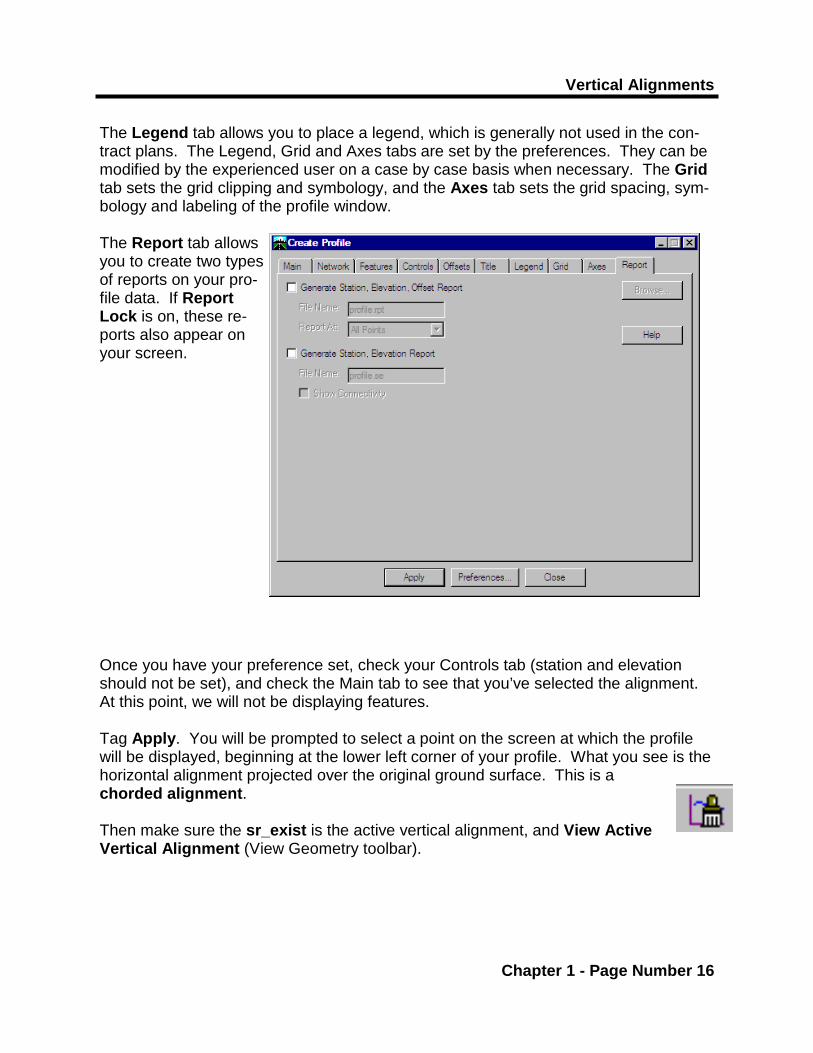
The Legend tab allows you to place a legend, which is generally not used in the con-tract plans. The Legend, Grid and Axes tabs are set by the preferences. They can be modified by the experienced user on a case by case basis when necessary. The Grid tab sets the grid clipping and symbology, and the Axes tab sets the grid spacing, sym-bology and labeling of the profile window. The Report tab allows you to create two types of reports on your pro-file data. If Report Lock is on, these re-ports also appear on your screen. Once you have your preference set, check your Controls tab (station and elevation should not be set), and check the Main tab to see that you’ve selected the alignment. At this point, we will not be displaying features. Tag Apply. You will be prompted to select a point on the screen at which the profile will be displayed, beginning at the lower left corner of your profile. What you see is the horizontal alignment projected over the original ground surface. This is a chorded alignment. Then make sure the sr_exist is the active vertical alignment, and View Active Vertical Alignment (View Geometry toolbar).

D2 Vertical Alignments and Profiles
Chapter 1 - Page Number 17
PREFERENCE SCALES: Preferences which include a scale factor will be selected to be placed with the global scale at a factor of 1. For example, Create Profile has several preferences to choose from, such as ny_250. This preference will automatically apply the necessary settings for a 250 scale profile. For preferences that do not have a scale factor attached, these preferences have been created at 100 scale. A global scale factor must be applied to change the scale. For example, to View Geometry Annotation on a 250 scale profile, the preference will be ny_proposed and the global scale factor must be set to 2.5.
*

Vertical Alignments
Chapter 1 - Page Number 18
You can see the PVI’s, dropped at the 3.0 meter interval, by using the View
Vertical Annotation tool. Select a preference (ny_existing), and make sure the correct alignments are in the windows. The preference will set the parameters in the Points, Curves, Tangents, Sight Distance, and Affixes tabs (because there is no scale factor attached to the pref-erences, you must first apply a factor of 2.5 in the global scale factor). If you zoom in, you’ll see that the vertical alignment has a PVI at every 3 meter interval, which is how it was created from surface. (These interval PVI’s may not necessarily match the intervals of hard pavement shots taken in the field)

D2 Vertical Alignments and Profiles
Chapter 1 - Page Number 19

Vertical Alignments
Chapter 1 - Page Number 20
Modifying the Vertical Alignment View the proposed vertical alignment sr_prop, which is a coordinated align-ment. To make a smooth transition between these two alignments, the over-lapping PVI’s of the vertical alignment from surface may be deleted. The De-lete PI icon from the Vertical Curve Set tools may be used to do this. Make sure the sr_exist alignment is active, as the active alignment is the one that the commands will be acting on.
Using the Distance and Constraint options on the dialog box, you can dynamically control the position of the screen cursor while using this command. The cursor position is filtered by the Distance value you provide. If the Dis-tance checkbox is not selected, the distance value is determined by the active vertical alignment. They determine the length of the
vertical curve that may be associated with the PVI’s. Tag Apply. Select the element on the vertical alignment you want to delete. The se-lected vertical PI and any elements affected by the deletion flash to indicate the extent of the change. You are then prompted to accept or reject his element. When you ac-cept the element, the vertical PVI is deleted from the active vertical alignment. Any tangents or curves connected to the vertical PVI’s are also deleted. If the deleted verti-cal PVI had two tangents connected to it, then the vertical PVI’s on the opposite ends of those tangents are connected with a new tangent. If curves exist at the neighboring vertical PVI’s they are recomputed using the point of intersection and the constraint you selected on the dialog box. After deleting the PVI (’s) re-annotate your vertical alignment (View Vertical Annotation). Save the geometry project.

D2 Vertical Alignments and Profiles
Chapter 1 - Page Number 21
Note that the alignment cannot have a prefix on the stations if exporting to ASCII. *

Vertical Alignments
Chapter 1 - Page Number 22
Modifying Vertical Alignments in ASCII Formats In order to have sr_exist meet with sr_prop, many PVI’s would have to be deleted. A better way to do this is to export the alignments to ASCII, delete the PVI’s in the sr_exist, and copy the remaining PVI’s into the sr_prop. Then import the new align-ment. (This method, though very popular at one time, is very rarely used) Exporting and importing from ASCII requires that no prefixes be attached to the alignment stationing. To remove the prefixes, go to Geometry > Hori-zontal Curve Set > Stationing. Highlight the selection in the Station Equations window, and tag Delete. This will eliminate the SR prefix.

D2 Vertical Alignments and Profiles
Chapter 1 - Page Number 23
Vertical Alignments
Chapter 1 - Page Number 24
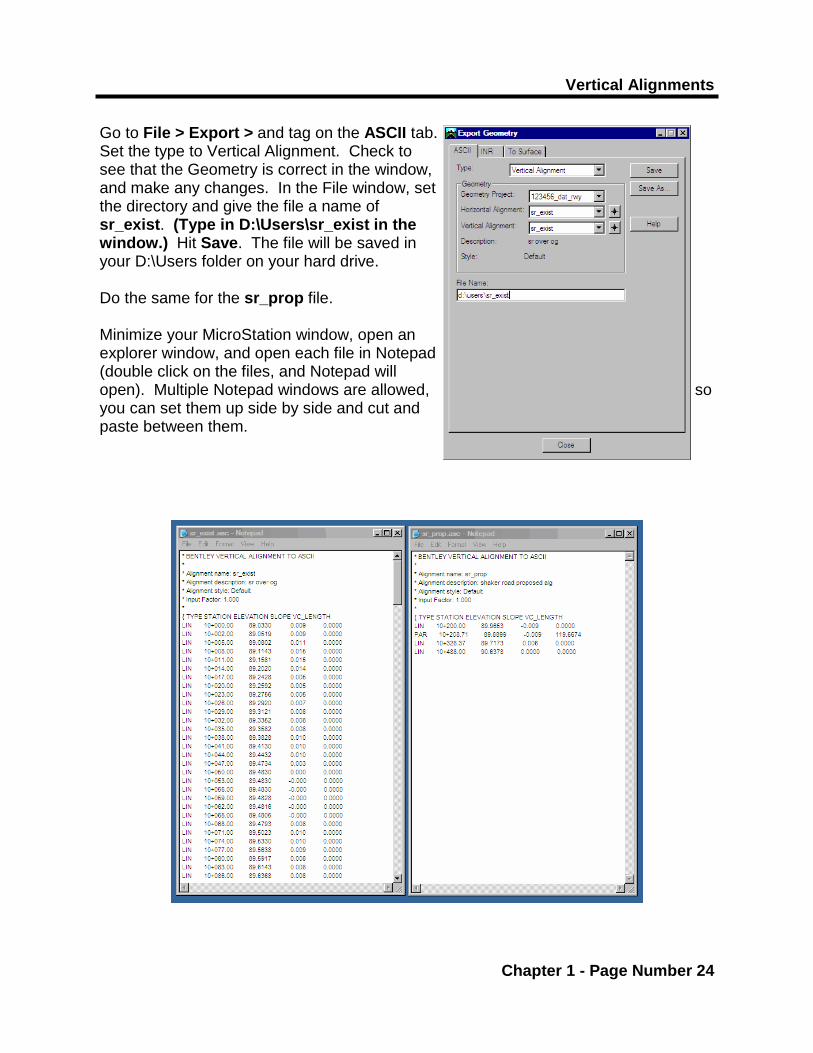
Go to File > Export > and tag on the ASCII tab. Set the type to Vertical Alignment. Check to see that the Geometry is correct in the window, and make any changes. In the File window, set the directory and give the file a name of sr_exist. (Type in D:\Users\sr_exist in the window.) Hit Save. The file will be saved in your D:\Users folder on your hard drive. Do the same for the sr_prop file. Minimize your MicroStation window, open an explorer window, and open each file in Notepad (double click on the files, and Notepad will open). Multiple Notepad windows are allowed, so you can set them up side by side and cut and paste between them.

D2 Vertical Alignments and Profiles
Chapter 1 - Page Number 25
Vertical Alignments
Chapter 1 - Page Number 26
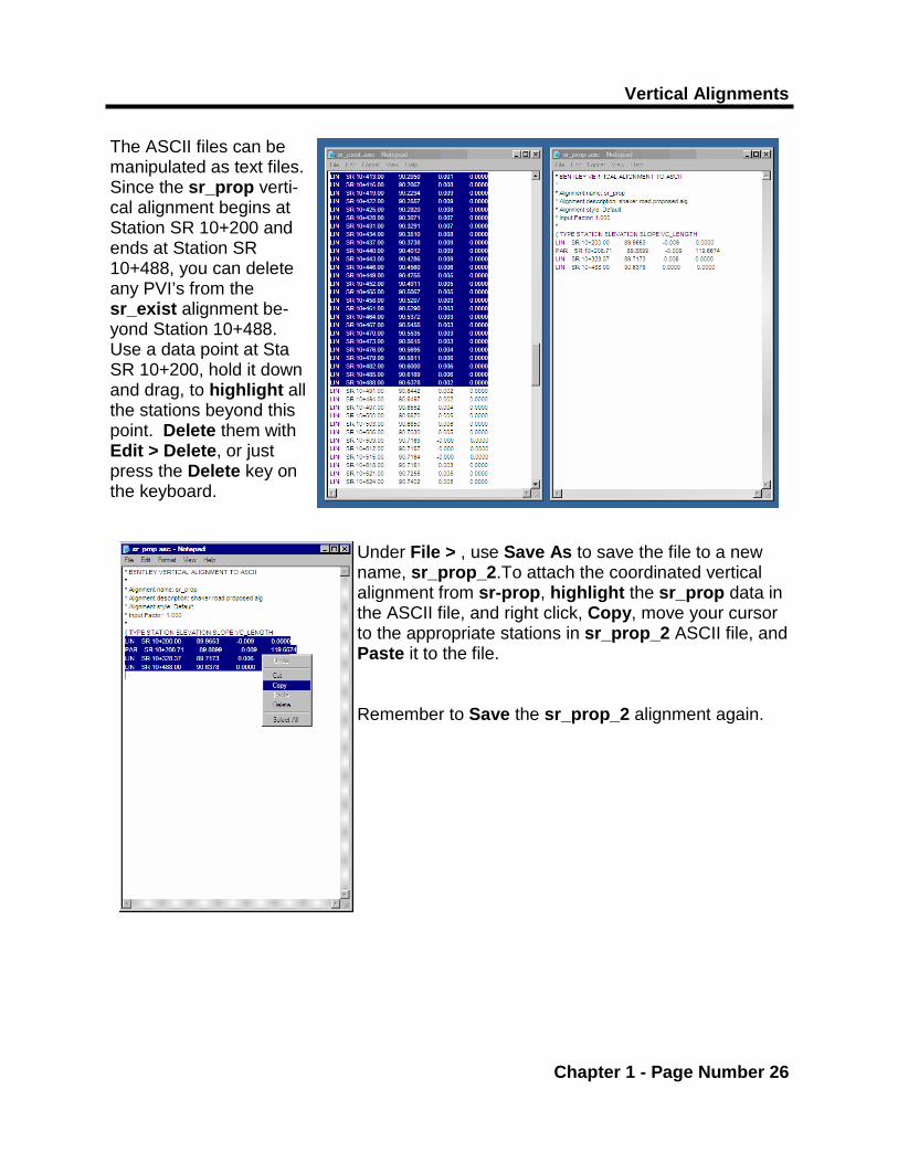
The ASCII files can be manipulated as text files. Since the sr_prop verti-cal alignment begins at Station SR 10+200 and ends at Station SR 10+488, you can delete any PVI’s from the sr_exist alignment be-yond Station 10+488. Use a data point at Sta SR 10+200, hold it down and drag, to highlight all the stations beyond this point. Delete them with Edit > Delete, or just press the Delete key on the keyboard.
Under File > , use Save As to save the file to a new name, sr_prop_2.To attach the coordinated vertical alignment from sr-prop, highlight the sr_prop data in the ASCII file, and right click, Copy, move your cursor to the appropriate stations in sr_prop_2 ASCII file, and Paste it to the file. Remember to Save the sr_prop_2 alignment again.

D2 Vertical Alignments and Profiles
Chapter 1 - Page Number 27

Vertical Alignments
Chapter 1 - Page Number 28
The alignment must be imported back into the ge-ometry project. In InRoads, go to File > Import > Geometry > ASCII tab. Select the type as Vertical Alignment. Place your cursor in the File Name window and hit Browse. Cancel out of the ProjectWise window and go to D:\Users, and select sr_prop_2, Open. Name and describe the alignment accordingly. Set the Style as AC_P. Make sure that the Geometry Project and Horizontal Alignment Targets are cor-rect. Tag Apply. The vertical alignment will show in the InRoads Geome-try. Save the Geometry Project. Delete the previous vertical alignment annotation, and redisplay the annotation for the sr_prop_2 (View Verti-cal Annotation).

D2 Vertical Alignments and Profiles
Chapter 1 - Page Number 29
Vertical Alignments
Chapter 1 - Page Number 30
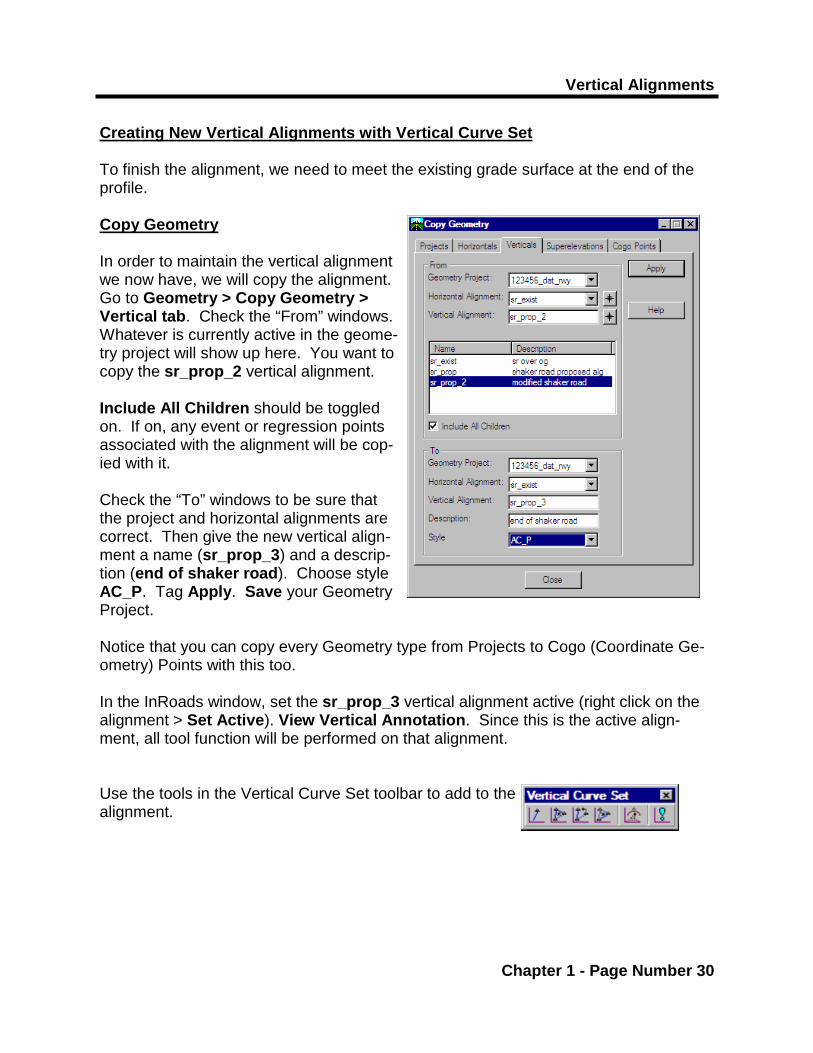
Creating New Vertical Alignments with Vertical Curve Set To finish the alignment, we need to meet the existing grade surface at the end of the profile. Copy Geometry In order to maintain the vertical alignment we now have, we will copy the alignment. Go to Geometry > Copy Geometry > Vertical tab. Check the “From” windows. Whatever is currently active in the geome-try project will show up here. You want to copy the sr_prop_2 vertical alignment. Include All Children should be toggled on. If on, any event or regression points associated with the alignment will be cop-ied with it. Check the “To” windows to be sure that the project and horizontal alignments are correct. Then give the new vertical align-ment a name (sr_prop_3) and a descrip-tion (end of shaker road). Choose style AC_P. Tag Apply. Save your Geometry Project. Notice that you can copy every Geometry type from Projects to Cogo (Coordinate Ge-ometry) Points with this too. In the InRoads window, set the sr_prop_3 vertical alignment active (right click on the alignment > Set Active). View Vertical Annotation. Since this is the active align-ment, all tool function will be performed on that alignment. Use the tools in the Vertical Curve Set toolbar to add to the alignment.

D2 Vertical Alignments and Profiles
Chapter 1 - Page Number 31
Vertical Alignments
Chapter 1 - Page Number 32
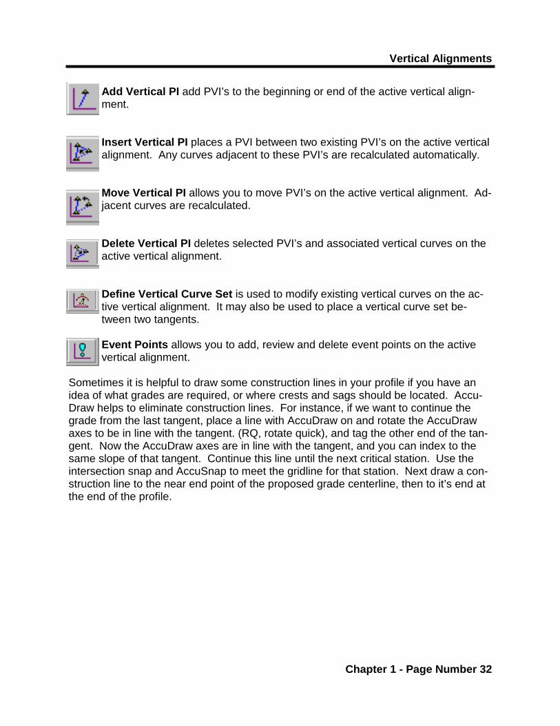
Add Vertical PI add PVI’s to the beginning or end of the active vertical align-ment. Insert Vertical PI places a PVI between two existing PVI’s on the active vertical alignment. Any curves adjacent to these PVI’s are recalculated automatically. Move Vertical PI allows you to move PVI’s on the active vertical alignment. Ad-jacent curves are recalculated. Delete Vertical PI deletes selected PVI’s and associated vertical curves on the active vertical alignment. Define Vertical Curve Set is used to modify existing vertical curves on the ac-tive vertical alignment. It may also be used to place a vertical curve set be-tween two tangents. Event Points allows you to add, review and delete event points on the active vertical alignment.
Sometimes it is helpful to draw some construction lines in your profile if you have an idea of what grades are required, or where crests and sags should be located. Accu-Draw helps to eliminate construction lines. For instance, if we want to continue the grade from the last tangent, place a line with AccuDraw on and rotate the AccuDraw axes to be in line with the tangent. (RQ, rotate quick), and tag the other end of the tan-gent. Now the AccuDraw axes are in line with the tangent, and you can index to the same slope of that tangent. Continue this line until the next critical station. Use the intersection snap and AccuSnap to meet the gridline for that station. Next draw a con-struction line to the near end point of the proposed grade centerline, then to it’s end at the end of the profile.

D2 Vertical Alignments and Profiles
Chapter 1 - Page Number 33
Vertical Alignments
Chapter 1 - Page Number 34
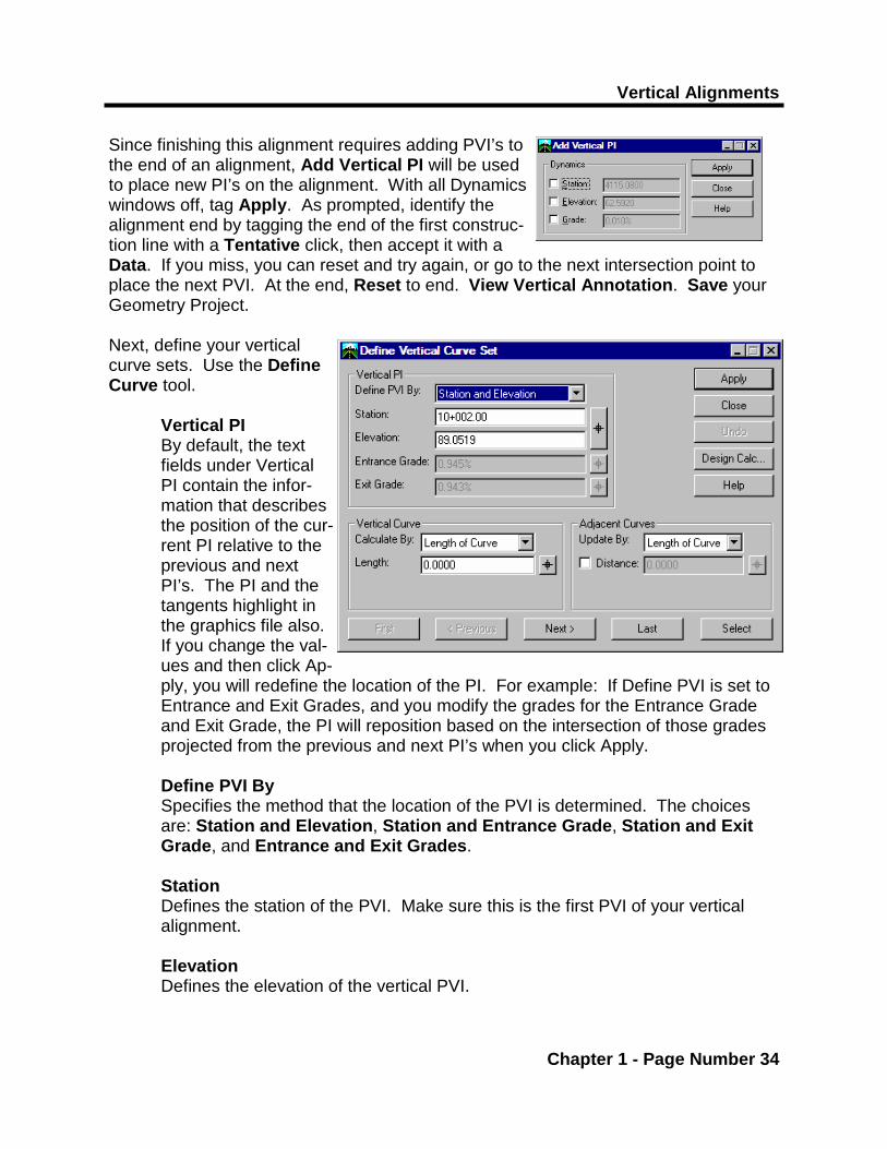
Since finishing this alignment requires adding PVI’s to the end of an alignment, Add Vertical PI will be used to place new PI’s on the alignment. With all Dynamics windows off, tag Apply. As prompted, identify the alignment end by tagging the end of the first construc-tion line with a Tentative click, then accept it with a Data. If you miss, you can reset and try again, or go to the next intersection point to place the next PVI. At the end, Reset to end. View Vertical Annotation. Save your Geometry Project. Next, define your vertical curve sets. Use the Define Curve tool.
Vertical PI By default, the text fields under Vertical PI contain the infor-mation that describes the position of the cur-rent PI relative to the previous and next PI’s. The PI and the tangents highlight in the graphics file also. If you change the val-ues and then click Ap-ply, you will redefine the location of the PI. For example: If Define PVI is set to Entrance and Exit Grades, and you modify the grades for the Entrance Grade and Exit Grade, the PI will reposition based on the intersection of those grades projected from the previous and next PI’s when you click Apply. Define PVI By Specifies the method that the location of the PVI is determined. The choices are: Station and Elevation, Station and Entrance Grade, Station and Exit Grade, and Entrance and Exit Grades. Station Defines the station of the PVI. Make sure this is the first PVI of your vertical alignment. Elevation Defines the elevation of the vertical PVI.

D2 Vertical Alignments and Profiles
Chapter 1 - Page Number 35

Vertical Alignments
Chapter 1 - Page Number 36
Entrance Grade Defines the grade of the tangent approaching the PVI. Exit Grade: Defines the grade of the tangent from the present PVI to the next PVI. Vertical Curve: Calculate By Specifies the method used to calculate the curve length. You can choose from the Length of Curve, r = (g2-g1)/L, Middle Ordinate, Pass-through, K = L/(g1-g2), and Unsymmetrical Length. Length: Defines the vertical curve length. Adjacent Curves: This area is utilized when you make an edit that affects the adjacent curve. If you change the elevation of the current PVI, it will recomputed the exit grade of the previous curve, entrance and exit grade of the current curve, and entrance grade of the next curve. The length of the adjacent curves will be preserved or recomputed based on the settings in this area. First, Previous, Next, Last Allows you to move from curve to curve. Select Allows you to select a vertical curve by tagging the curve in a profile in the graphics file. Design Calc. Activates the Vertical Design Calculator dialog box which allows you to com-pute the vertical curve utilizing six different methods. After you have com-puted the vertical curve to your satisfaction, tagging the OK button will define the curve in the Define Vertical Curve dialog box. Apply Initiates the command. The dialog box will remain on the screen. The prompt “Successful Completion” will appear when a solution is achieved, and the vertical curve will appear in the profile. If there is no solution for the pa-rameters entered, then you will be prompted with whatever problem was found. For example: “solution overlaps” usually means that the curve length was too long.
D2 Vertical Alignments and Profiles
Chapter 1 - Page Number 37
* Note that there is no design criteria set for this example. It is for demonstration pur-poses only. It is the designer’s responsibility to check design criteria prior to designing a vertical alignment.
Vertical Alignments
Chapter 1 - Page Number 38
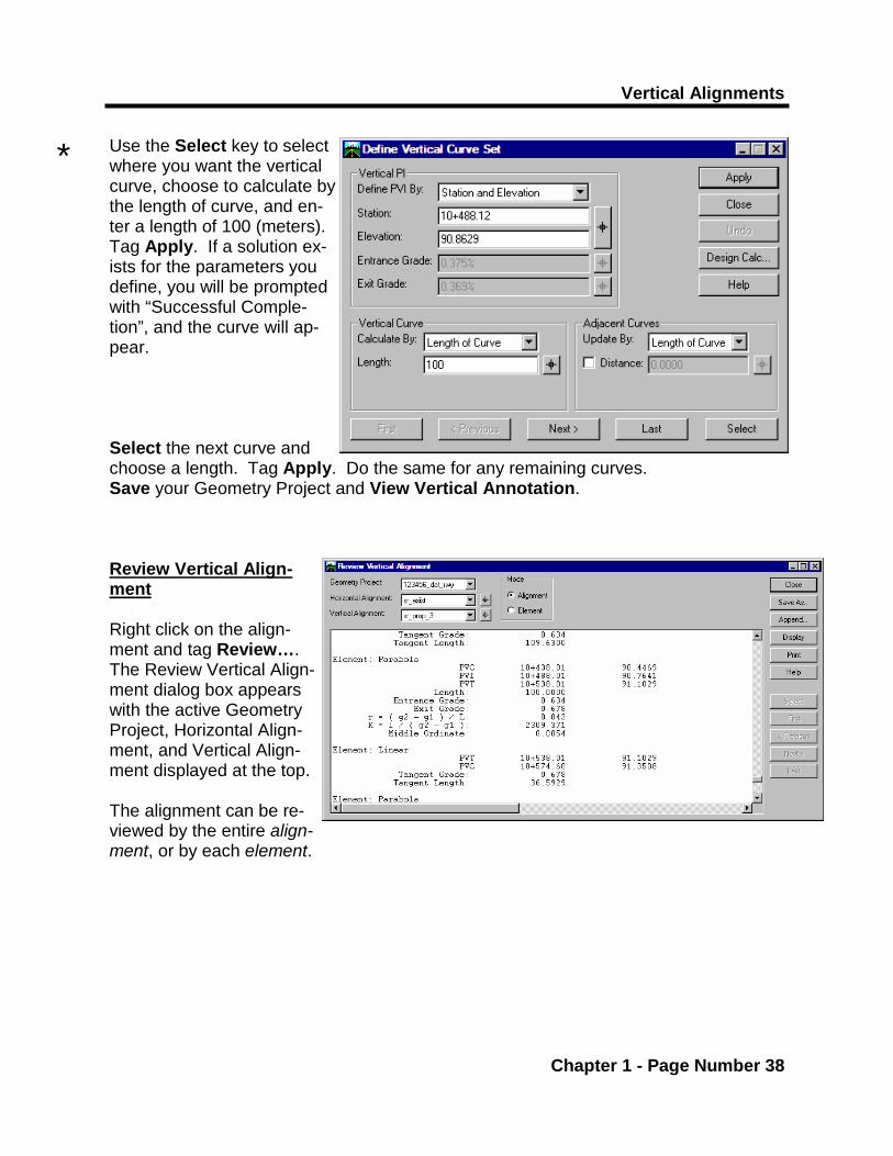
Use the Select key to select where you want the vertical curve, choose to calculate by the length of curve, and en-ter a length of 100 (meters). Tag Apply. If a solution ex-ists for the parameters you define, you will be prompted with “Successful Comple-tion”, and the curve will ap-pear. Select the next curve and choose a length. Tag Apply. Do the same for any remaining curves. Save your Geometry Project and View Vertical Annotation. Review Vertical Align-ment Right click on the align-ment and tag Review…. The Review Vertical Align-ment dialog box appears with the active Geometry Project, Horizontal Align-ment, and Vertical Align-ment displayed at the top. The alignment can be re-viewed by the entire align-ment, or by each element.
*

D2 Vertical Alignments and Profiles
Chapter 1 - Page Number 39
Vertical Alignments
Chapter 1 - Page Number 40
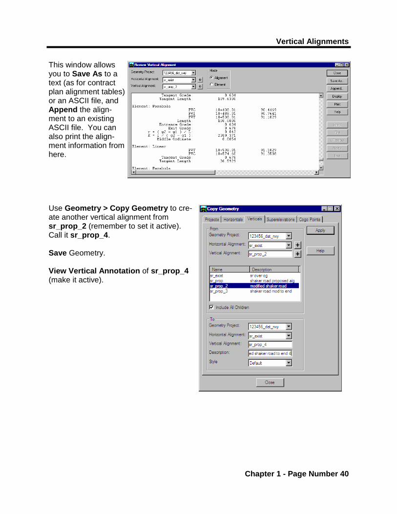
This window allows you to Save As to a text (as for contract plan alignment tables) or an ASCII file, and Append the align-ment to an existing ASCII file. You can also print the align-ment information from here. Use Geometry > Copy Geometry to cre-ate another vertical alignment from sr_prop_2 (remember to set it active). Call it sr_prop_4. Save Geometry. View Vertical Annotation of sr_prop_4 (make it active).

D2 Vertical Alignments and Profiles
Chapter 1 - Page Number 41
* While placing PI’s by the Key-In method, it is sometimes necessary to adjust your view window so that you can see the next PI. Do this “on the fly”, and just hit one reset to get the “stringing” alignment and your cursor back.
Vertical Alignments
Chapter 1 - Page Number 42
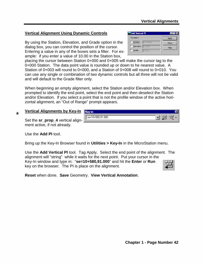
Vertical Alignment Using Dynamic Controls By using the Station, Elevation, and Grade option in the dialog box, you can control the position of the cursor. Entering a value in any of the boxes sets a filter. For ex-ample: if you enter a value of 10.00 in the Station box, placing the cursor between Station 0+000 and 0+005 will make the cursor tag to the 0+000 Station. The data point value is rounded up or down to he nearest value. A Station of 0+003 will round to 0+000, and a Station of 0+008 will round to 0+010. You can use any single or combination of two dynamic controls but all three will not be valid and will default to the Grade filter only. When beginning an empty alignment, select the Station and/or Elevation box. When prompted to identify the end point, select the end point and then deselect the Station and/or Elevation. If you select a point that is not the profile window of the active hori-zontal alignment, an “Out of Range” prompt appears. Vertical Alignments by Key-In
Set the sr_prop_4 vertical align-ment active, if not already. Use the Add PI tool. Bring up the Key-In Browser found in Utilities > Key-In in the MicroStation menu. Use the Add Vertical PI tool. Tag Apply. Select the end point of the alignment. The alignment will “string” while it waits for the next point. Put your cursor in the Key-In window and type in: “se=10+580,91.000” and hit the Enter or Run key on the browser. The PI is place on the alignment. Reset when done. Save Geometry. View Vertical Annotation.
*
D2 Vertical Alignments and Profiles
Chapter 1 - Page Number 43
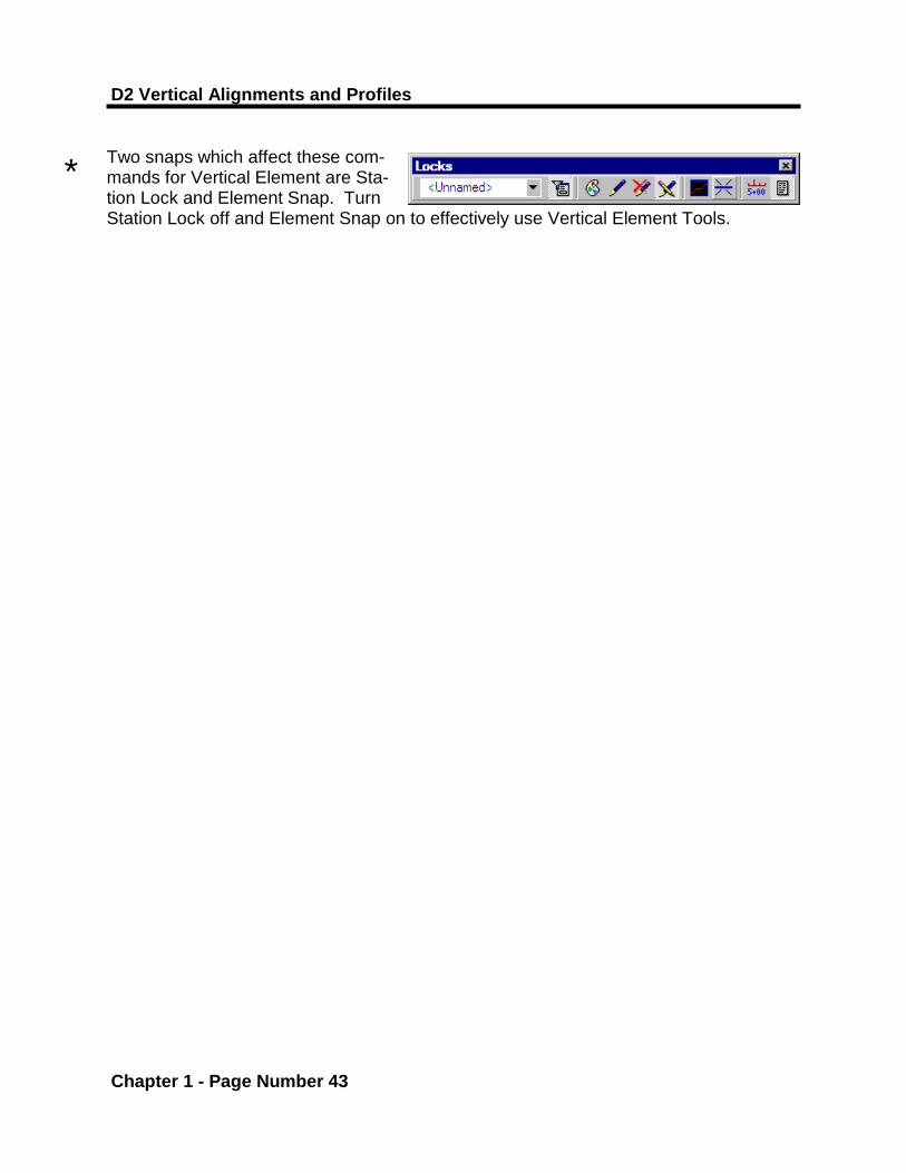
Two snaps which affect these com-mands for Vertical Element are Sta-tion Lock and Element Snap. Turn Station Lock off and Element Snap on to effectively use Vertical Element Tools.
*
Vertical Alignments
Chapter 1 - Page Number 44
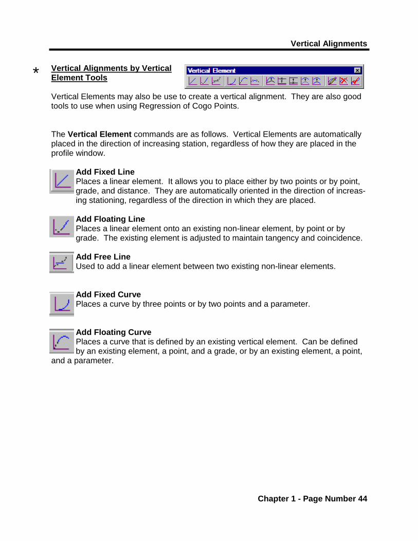
Vertical Alignments by Vertical Element Tools Vertical Elements may also be use to create a vertical alignment. They are also good tools to use when using Regression of Cogo Points. The Vertical Element commands are as follows. Vertical Elements are automatically placed in the direction of increasing station, regardless of how they are placed in the profile window.
Add Fixed Line Places a linear element. It allows you to place either by two points or by point, grade, and distance. They are automatically oriented in the direction of increas-ing stationing, regardless of the direction in which they are placed. Add Floating Line Places a linear element onto an existing non-linear element, by point or by grade. The existing element is adjusted to maintain tangency and coincidence. Add Free Line Used to add a linear element between two existing non-linear elements.
Add Fixed Curve Places a curve by three points or by two points and a parameter. Add Floating Curve Places a curve that is defined by an existing vertical element. Can be defined by an existing element, a point, and a grade, or by an existing element, a point,
and a parameter.
*

D2 Vertical Alignments and Profiles
Chapter 1 - Page Number 45
Vertical Alignments
Chapter 1 - Page Number 46
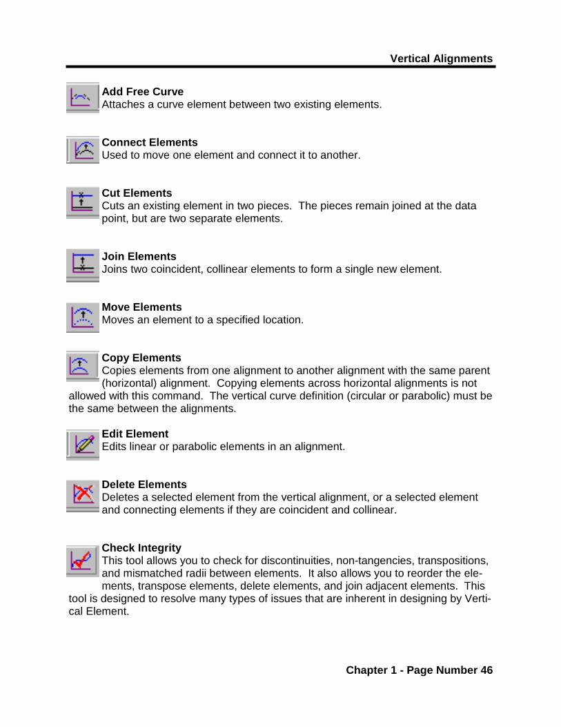
Add Free Curve Attaches a curve element between two existing elements. Connect Elements Used to move one element and connect it to another. Cut Elements Cuts an existing element in two pieces. The pieces remain joined at the data point, but are two separate elements.
Join Elements Joins two coincident, collinear elements to form a single new element. Move Elements Moves an element to a specified location. Copy Elements Copies elements from one alignment to another alignment with the same parent (horizontal) alignment. Copying elements across horizontal alignments is not
allowed with this command. The vertical curve definition (circular or parabolic) must be the same between the alignments.
Edit Element Edits linear or parabolic elements in an alignment. Delete Elements Deletes a selected element from the vertical alignment, or a selected element and connecting elements if they are coincident and collinear.
Check Integrity This tool allows you to check for discontinuities, non-tangencies, transpositions, and mismatched radii between elements. It also allows you to reorder the ele-ments, transpose elements, delete elements, and join adjacent elements. This
tool is designed to resolve many types of issues that are inherent in designing by Verti-cal Element.

D2 Vertical Alignments and Profiles
Chapter 1 - Page Number 47
Vertical Alignments
Chapter 1 - Page Number 48
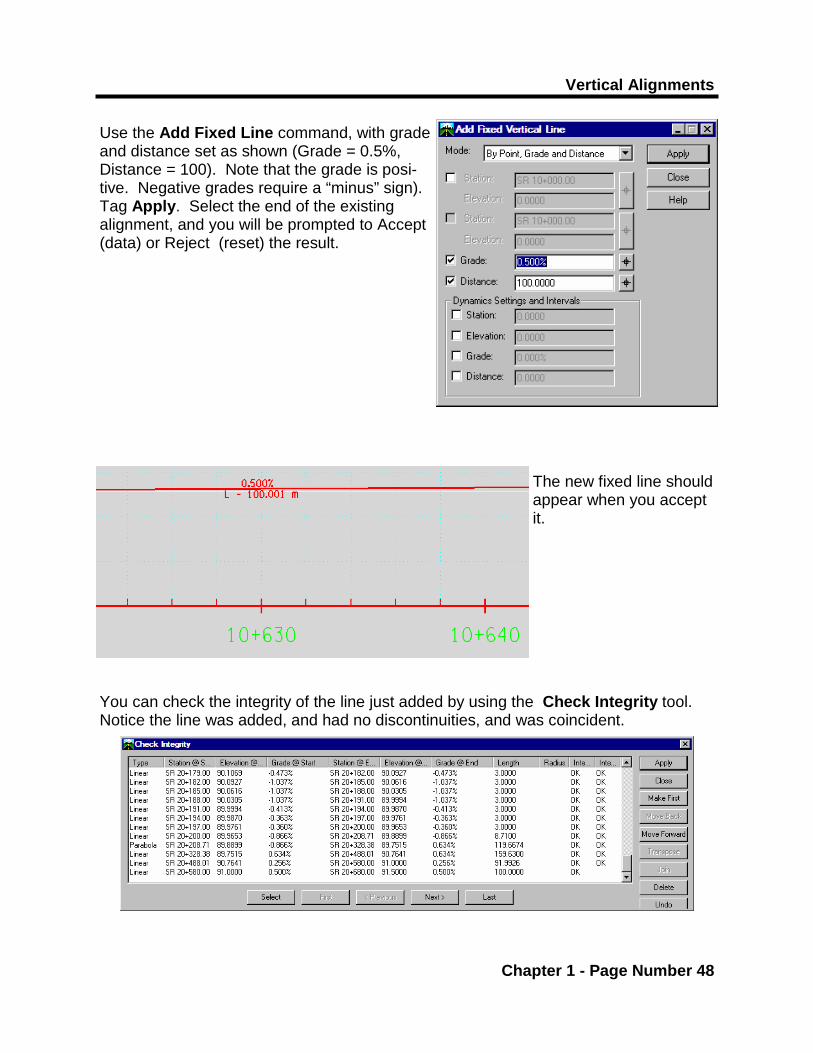
Use the Add Fixed Line command, with grade and distance set as shown (Grade = 0.5%, Distance = 100). Note that the grade is posi-tive. Negative grades require a “minus” sign). Tag Apply. Select the end of the existing alignment, and you will be prompted to Accept (data) or Reject (reset) the result.
The new fixed line should appear when you accept it.
You can check the integrity of the line just added by using the Check Integrity tool. Notice the line was added, and had no discontinuities, and was coincident.

D2 Vertical Alignments and Profiles
Chapter 1 - Page Number 49
Vertical Alignments
Chapter 1 - Page Number 50
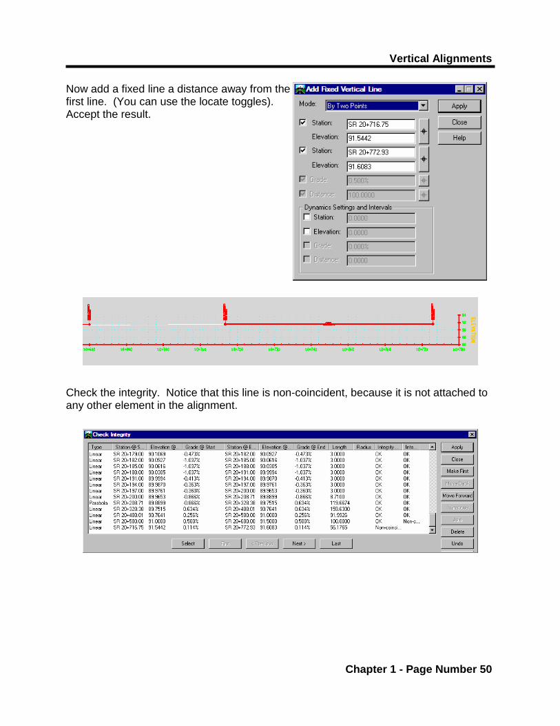
Now add a fixed line a distance away from the first line. (You can use the locate toggles). Accept the result. Check the integrity. Notice that this line is non-coincident, because it is not attached to any other element in the alignment.

D2 Vertical Alignments and Profiles
Chapter 1 - Page Number 51

Vertical Alignments
Chapter 1 - Page Number 52
Now place a Free Curve between the first fixed line and the second, with a length of 100 (meters). Tag Apply. Select the first element, then the sec-ond element, then Accept the result. Check the integrity of the alignment. Notice that the discontinuities have been resolved. If you had chosen to add a Floating Vertical Curve by Point and Parameter, you can enter a radius. A value could be entered in the point, or it can be allowed to “float”. Notice that the curve “rubber bands” after you select the first element, and you can pick a point to end the curve.

D2 Vertical Alignments and Profiles
Chapter 1 - Page Number 53
Vertical Alignments
Chapter 1 - Page Number 54
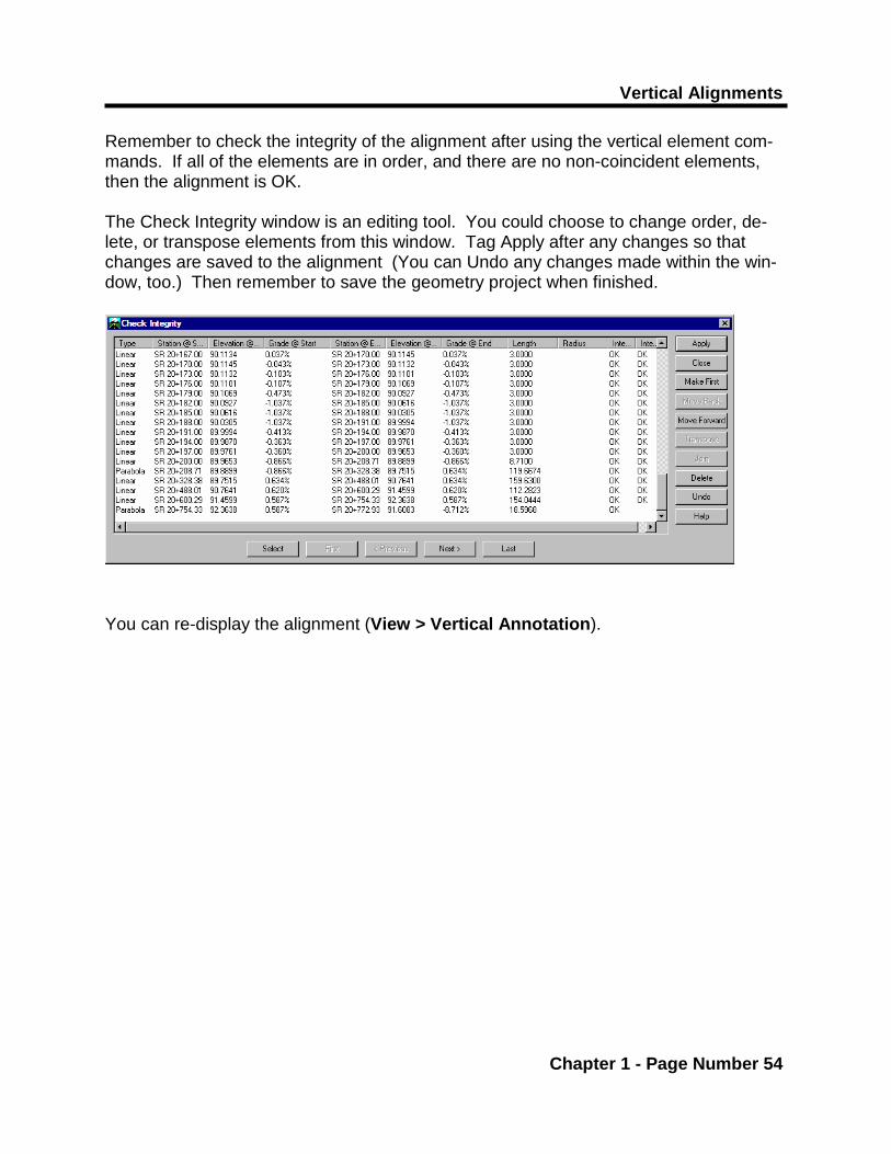
Remember to check the integrity of the alignment after using the vertical element com-mands. If all of the elements are in order, and there are no non-coincident elements, then the alignment is OK. The Check Integrity window is an editing tool. You could choose to change order, de-lete, or transpose elements from this window. Tag Apply after any changes so that changes are saved to the alignment (You can Undo any changes made within the win-dow, too.) Then remember to save the geometry project when finished.
You can re-display the alignment (View > Vertical Annotation).

Profiles
Chapter 2 - Page Number 2
Chapter 2 Profiles
Introduction...
This chapter will demonstrate annotation of profiles and preparing profiles for plan sheets.

D2 Vertical Alignments and Profiles
Chapter 2 - Page Number 3
Profiles
Chapter 2 - Page Number 4
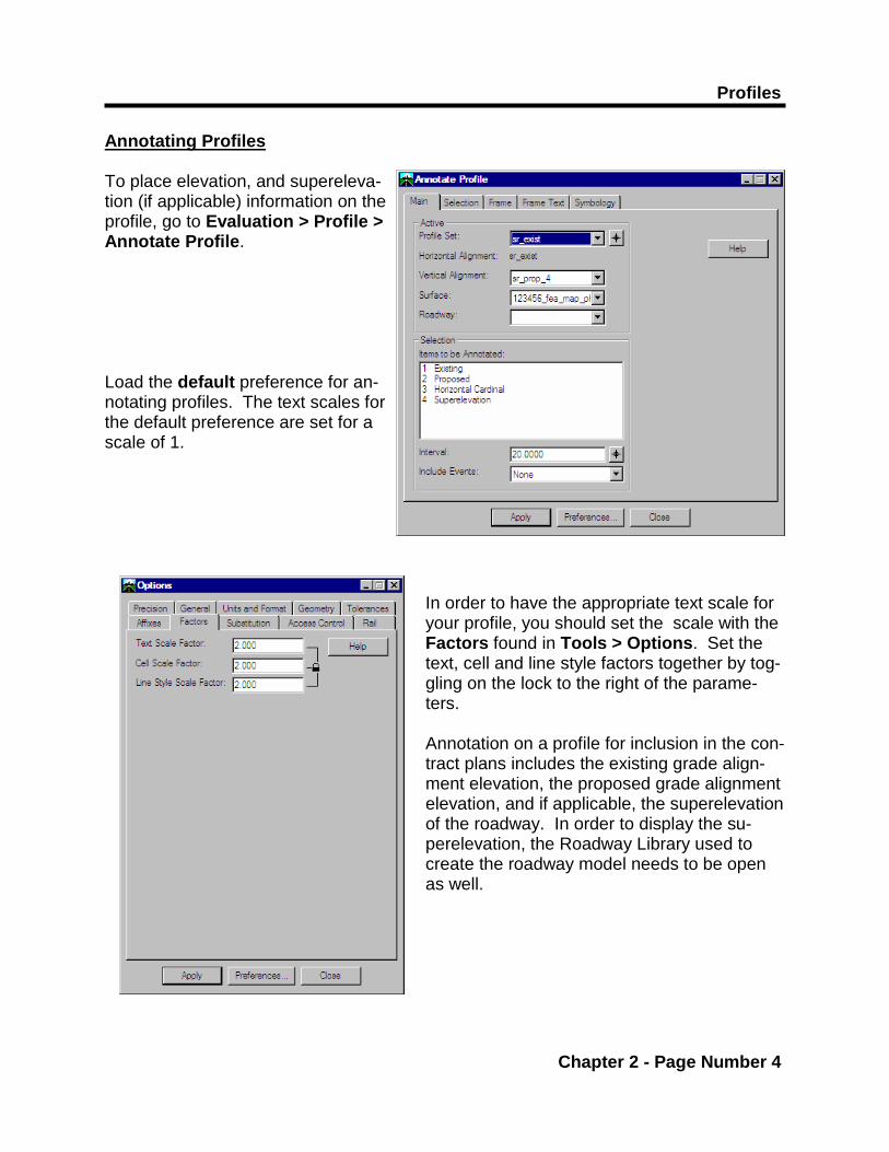
Annotating Profiles To place elevation, and supereleva-tion (if applicable) information on the profile, go to Evaluation > Profile > Annotate Profile. Load the default preference for an-notating profiles. The text scales for the default preference are set for a scale of 1.
In order to have the appropriate text scale for your profile, you should set the scale with the Factors found in Tools > Options. Set the text, cell and line style factors together by tog-gling on the lock to the right of the parame-ters. Annotation on a profile for inclusion in the con-tract plans includes the existing grade align-ment elevation, the proposed grade alignment elevation, and if applicable, the superelevation of the roadway. In order to display the su-perelevation, the Roadway Library used to create the roadway model needs to be open as well.

D2 Vertical Alignments and Profiles
Chapter 2 - Page Number 5
Under the Frame Text tab, there are parameters for Collision-Free text. These are tolerances and spacing specified to prevent text from collid-ing while annotating on the profile. However, text scaling can hinder this operation, and prevent the text from being annotated at the desired inter-val. If you are having trouble anno-tating the profile, check these pa-rameters.
*
Profiles
Chapter 2 - Page Number 6
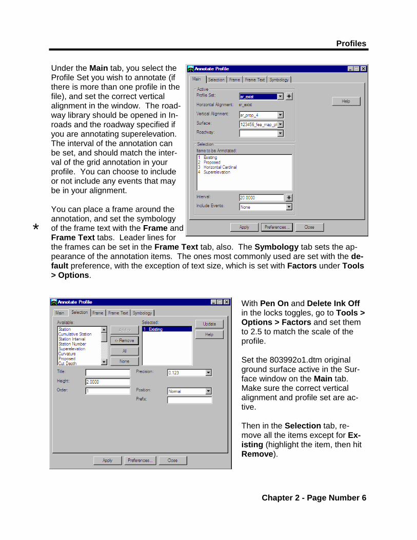
Under the Main tab, you select the Profile Set you wish to annotate (if there is more than one profile in the file), and set the correct vertical alignment in the window. The road-way library should be opened in In-roads and the roadway specified if you are annotating superelevation. The interval of the annotation can be set, and should match the inter-val of the grid annotation in your profile. You can choose to include or not include any events that may be in your alignment. You can place a frame around the annotation, and set the symbology of the frame text with the Frame and Frame Text tabs. Leader lines for the frames can be set in the Frame Text tab, also. The Symbology tab sets the ap-pearance of the annotation items. The ones most commonly used are set with the de-fault preference, with the exception of text size, which is set with Factors under Tools > Options.
With Pen On and Delete Ink Off in the locks toggles, go to Tools > Options > Factors and set them to 2.5 to match the scale of the profile. Set the 803992o1.dtm original ground surface active in the Sur-face window on the Main tab. Make sure the correct vertical alignment and profile set are ac-tive. Then in the Selection tab, re-move all the items except for Ex-isting (highlight the item, then hit Remove).
*

D2 Vertical Alignments and Profiles
Chapter 2 - Page Number 7

Profiles
Chapter 2 - Page Number 8
Tag Apply. The existing grade over the alignment will annotate on the profile with an ex-isting text style. Leave the Delete Ink lock off, Re-move the Existing item from the Se-lection tab, and Add the Proposed. Tag Apply.
The proposed alignment eleva-tions (from the active vertical alignment) will display with a proposed text style

D2 Vertical Alignments and Profiles
Chapter 2 - Page Number 9

Profiles
Chapter 2 - Page Number 10
To display the superelevation, there must be a superelevation for the horizontal align-ment and the Roadway Library associated with the alignment must also be open. To display superelevation, Remove Proposed and Add Superelevation. Tag Apply. The active superelevation is annotated on the profile. [This example has no superelevation associated with the alignment.] Superelevation tends to collide with the bottom axis, but is easily moved as a graphic group using AccuDraw.

D2 Vertical Alignments and Profiles
Chapter 2 - Page Number 11
Profiles
Chapter 2 - Page Number 12
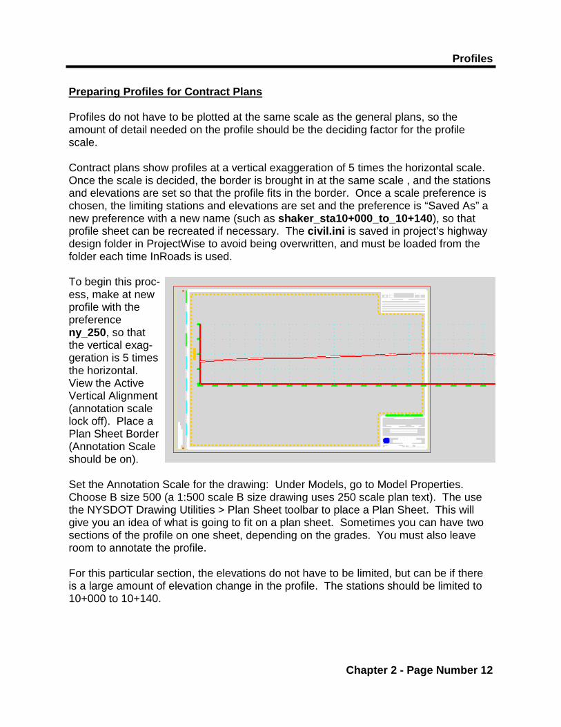
Preparing Profiles for Contract Plans Profiles do not have to be plotted at the same scale as the general plans, so the amount of detail needed on the profile should be the deciding factor for the profile scale. Contract plans show profiles at a vertical exaggeration of 5 times the horizontal scale. Once the scale is decided, the border is brought in at the same scale , and the stations and elevations are set so that the profile fits in the border. Once a scale preference is chosen, the limiting stations and elevations are set and the preference is “Saved As” a new preference with a new name (such as shaker_sta10+000_to_10+140), so that profile sheet can be recreated if necessary. The civil.ini is saved in project’s highway design folder in ProjectWise to avoid being overwritten, and must be loaded from the folder each time InRoads is used. To begin this proc-ess, make at new profile with the preference ny_250, so that the vertical exag-geration is 5 times the horizontal. View the Active Vertical Alignment (annotation scale lock off). Place a Plan Sheet Border (Annotation Scale should be on). Set the Annotation Scale for the drawing: Under Models, go to Model Properties. Choose B size 500 (a 1:500 scale B size drawing uses 250 scale plan text). The use the NYSDOT Drawing Utilities > Plan Sheet toolbar to place a Plan Sheet. This will give you an idea of what is going to fit on a plan sheet. Sometimes you can have two sections of the profile on one sheet, depending on the grades. You must also leave room to annotate the profile. For this particular section, the elevations do not have to be limited, but can be if there is a large amount of elevation change in the profile. The stations should be limited to 10+000 to 10+140.
D2 Vertical Alignments and Profiles
Chapter 2 - Page Number 13
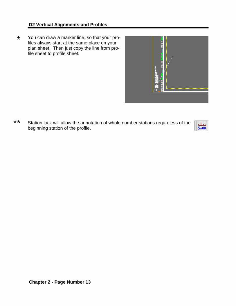
You can draw a marker line, so that your pro-files always start at the same place on your plan sheet. Then just copy the line from pro-file sheet to profile sheet. Station lock will allow the annotation of whole number stations regardless of the beginning station of the profile.
*
**
Profiles
Chapter 2 - Page Number 14
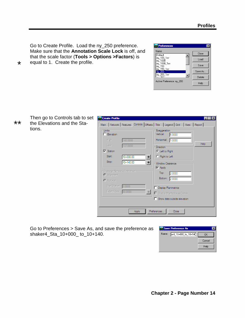
Go to Create Profile. Load the ny_250 preference. Make sure that the Annotation Scale Lock is off, and that the scale factor (Tools > Options >Factors) is equal to 1. Create the profile. Then go to Controls tab to set the Elevations and the Sta-tions. Go to Preferences > Save As, and save the preference as shaker4_Sta_10+000_ to_10+140.
*
**

D2 Vertical Alignments and Profiles
Chapter 2 - Page Number 15
Profiles
Chapter 2 - Page Number 16
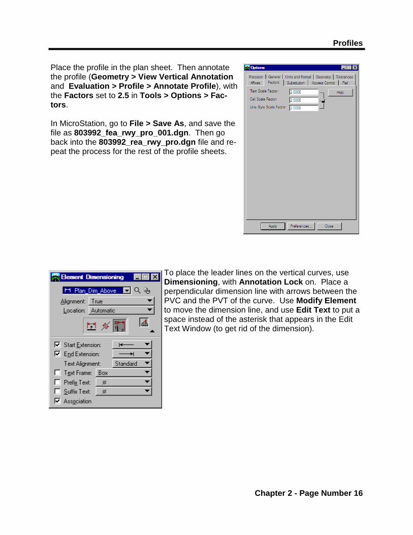
Place the profile in the plan sheet. Then annotate the profile (Geometry > View Vertical Annotation and Evaluation > Profile > Annotate Profile), with the Factors set to 2.5 in Tools > Options > Fac-tors. In MicroStation, go to File > Save As, and save the file as 803992_fea_rwy_pro_001.dgn. Then go back into the 803992_rea_rwy_pro.dgn file and re-peat the process for the rest of the profile sheets.
To place the leader lines on the vertical curves, use Dimensioning, with Annotation Lock on. Place a perpendicular dimension line with arrows between the PVC and the PVT of the curve. Use Modify Element to move the dimension line, and use Edit Text to put a space instead of the asterisk that appears in the Edit Text Window (to get rid of the dimension).
D2 Vertical Alignments and Profiles
Chapter 2 - Page Number 17
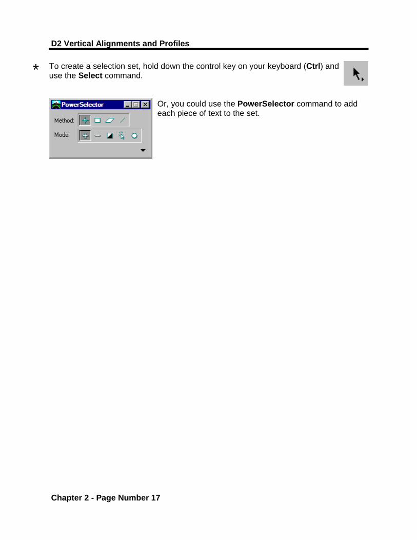
To create a selection set, hold down the control key on your keyboard (Ctrl) and use the Select command.
Or, you could use the PowerSelector command to add each piece of text to the set.
*
Profiles
Chapter 2 - Page Number 18
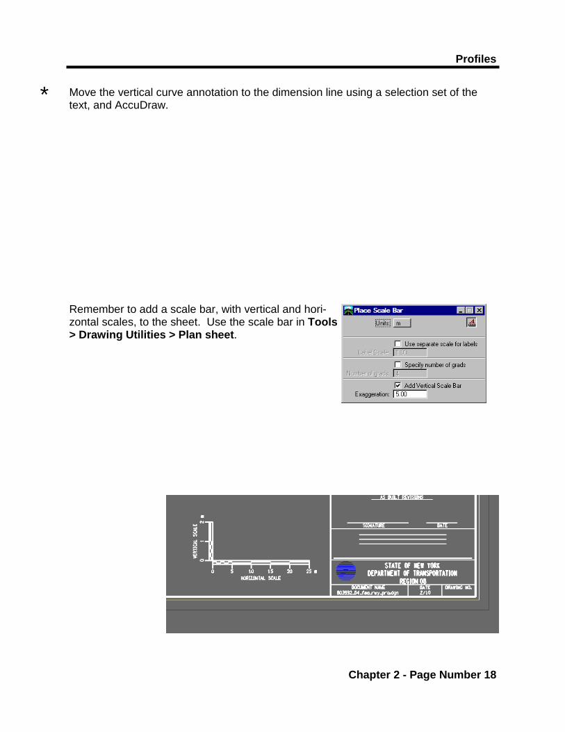
Move the vertical curve annotation to the dimension line using a selection set of the text, and AccuDraw. Remember to add a scale bar, with vertical and hori-zontal scales, to the sheet. Use the scale bar in Tools > Drawing Utilities > Plan sheet.
*