Embed Size (px)
Citation preview

VERTICAL AHU
INSTALLATION MANUAL
BULLETIN 30-015.003
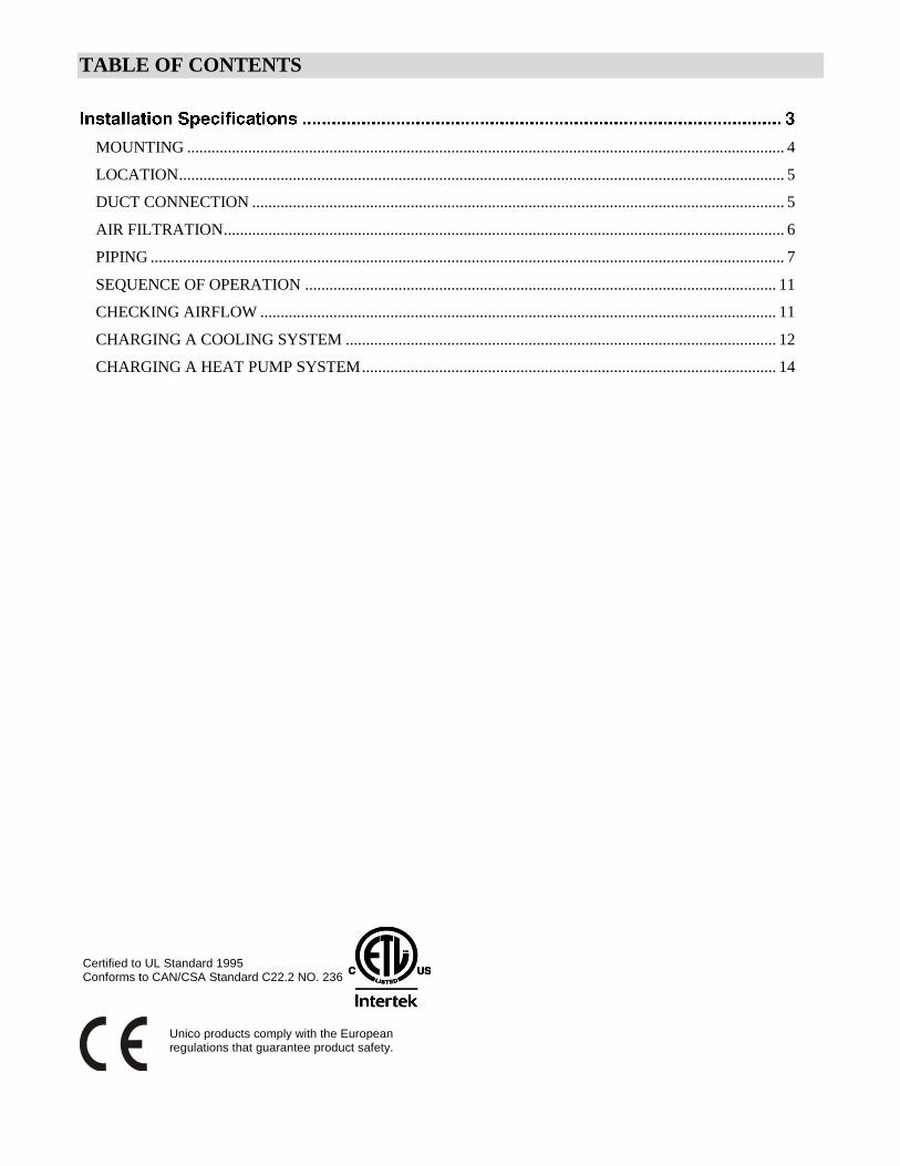
TABLE OF CONTENTS
MOUNTING ................................................................................................................................................... 4
LOCATION ..................................................................................................................................................... 5
DUCT CONNECTION ................................................................................................................................... 5
AIR FILTRATION .......................................................................................................................................... 6
PIPING ............................................................................................................................................................ 7
SEQUENCE OF OPERATION .................................................................................................................... 11
CHECKING AIRFLOW ............................................................................................................................... 11
CHARGING A COOLING SYSTEM .......................................................................................................... 12
CHARGING A HEAT PUMP SYSTEM ...................................................................................................... 14
Certified to UL Standard 1995Conforms to CAN/CSA Standard C22.2 NO. 236
Unico products comply with the Europeanregulations that guarantee product safety.
Bulletin 30-015.003
Copyright © 2017 Unico Inc. Page 3
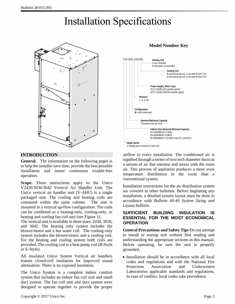
Installation Specifications
Model Number Key
V24 30 B 1 EC2BX
Cabinet Size (Nominal Minimum Capacity24=24000Btu/hr (7.0kW)30=30000Btu/hr (8.8kW)36=36000Btu/hr (10.5kW) (only EC1 and EC2)
Nominal Maximum Capacity
Thousands Btu per hour
Power Supply, Motor TypeEC1=1,50/60,120 variable-speedEC2=1,50/60,208/230 variable speed
Configuration
B= both (universal)
-
Model SeriesV=Single piece vertical unit (fan coil)
Revision1, 2, 3, etc.
Cooling Coil
B=ac/heat pump coil, 3-row with R410A TXVE=ac/heat pump coil, 4-row with R410A TXV
Heating CoilX=non includedH=hot water coil included
INTRODUCTION
General. The information on the following pages is
to help the installer save time, provide the best possible
installation and insure continuous trouble-free
operation.
Scope. These instructions apply to the Unico
V2430/3036/3642 Vertical Air Handler Unit. The
Unico vertical air handler unit (V-AHU) is a single
packaged unit. The cooling and heating coils are
contained within the same cabinet. The unit is
mounted in a vertical up-flow configuration. The coils
can be combined as a heating-only, cooling-only, or
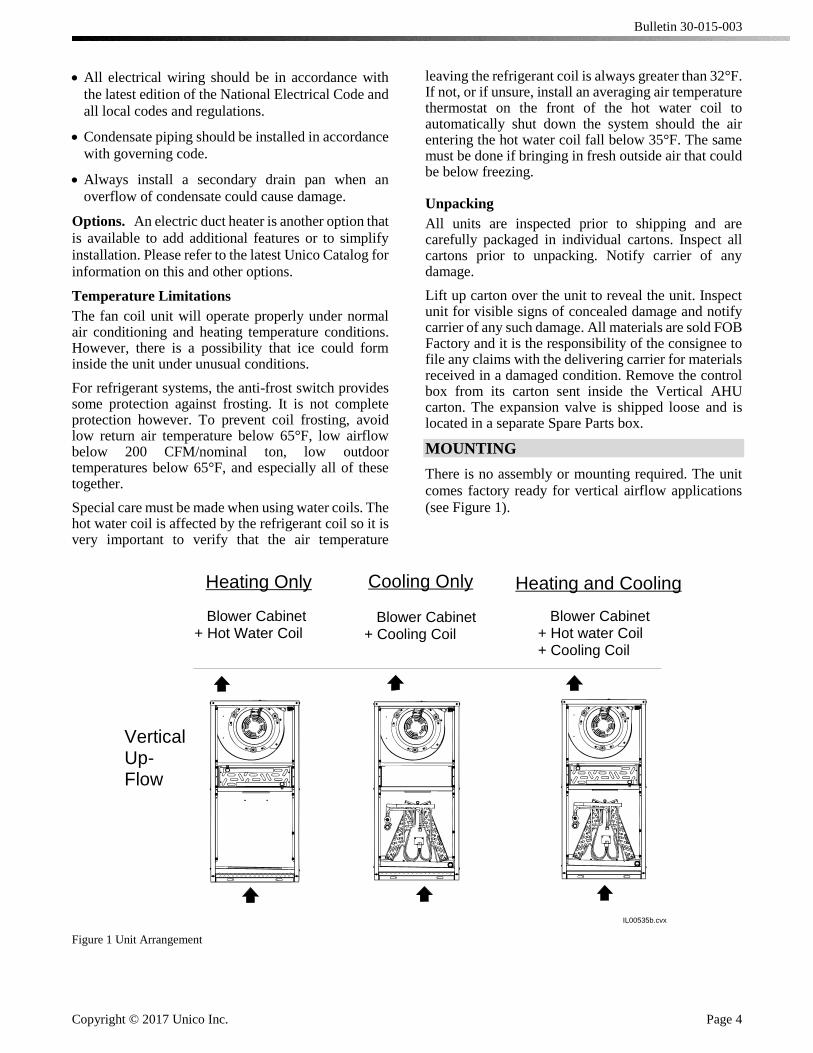
heating and cooling fan coil unit (see Figure 1). The vertical unit is available in three sizes: 2430, 3036, and 3642. The heating only system includes the blower/motor and a hot water coil. The cooling only system includes the blower/motor and a cooling coil. For the heating and cooling system both coils are provided. The cooling coil is a heat pump coil (B-Style or E-Style).
All insulated Unico System Vertical air handlers feature closed-cell insulation for improved sound attenuation. There is no exposed insulation.
The Unico System is a complete indoor comfort
system that includes an indoor fan coil unit and small
duct system. The fan coil unit and duct system were
designed to operate together to provide the proper
airflow in every installation. The conditioned air is
supplied through a series of two-inch diameter ducts as
a stream of air that entrains and mixes with the room
air. This process of aspiration produces a more even
temperature distribution in the room than a
conventional system.
Installation instructions for the air distribution system
are covered in other bulletins. Before beginning any
installation, a detailed system layout must be done in
accordance with Bulletin 40-40 System Sizing and
Layout bulletin.
SUFFICIENT BUILDING INSULATION IS
ESSENTIAL FOR THE MOST ECONOMICAL
OPERATION
General Precautions and Safety Tips Do not attempt
to install or startup unit without first reading and
understanding the appropriate sections in this manual.
Before operating, be sure the unit is properly
grounded.
Installation should be in accordance with all local
codes and regulations and with the National Fire
Protection Association and Underwriters
Laboratories applicable standards and regulations.
In case of conflict, local codes take precedence.
Bulletin 30-015-003
Copyright © 2017 Unico Inc. Page 4
All electrical wiring should be in accordance with
the latest edition of the National Electrical Code and
all local codes and regulations.
Condensate piping should be installed in accordance
with governing code.
Always install a secondary drain pan when an
overflow of condensate could cause damage.
Options. An electric duct heater is another option that
is available to add additional features or to simplify
installation. Please refer to the latest Unico Catalog for
information on this and other options.
Temperature Limitations
The fan coil unit will operate properly under normal air conditioning and heating temperature conditions. However, there is a possibility that ice could form inside the unit under unusual conditions.
For refrigerant systems, the anti-frost switch provides some protection against frosting. It is not complete protection however. To prevent coil frosting, avoid low return air temperature below 65°F, low airflow below 200 CFM/nominal ton, low outdoor temperatures below 65°F, and especially all of these together.
Special care must be made when using water coils. The hot water coil is affected by the refrigerant coil so it is very important to verify that the air temperature
leaving the refrigerant coil is always greater than 32°F. If not, or if unsure, install an averaging air temperature thermostat on the front of the hot water coil to automatically shut down the system should the air entering the hot water coil fall below 35°F. The same must be done if bringing in fresh outside air that could be below freezing.
Unpacking
All units are inspected prior to shipping and are carefully packaged in individual cartons. Inspect all cartons prior to unpacking. Notify carrier of any damage.
Lift up carton over the unit to reveal the unit. Inspect unit for visible signs of concealed damage and notify carrier of any such damage. All materials are sold FOB Factory and it is the responsibility of the consignee to file any claims with the delivering carrier for materials received in a damaged condition. Remove the control box from its carton sent inside the Vertical AHU carton. The expansion valve is shipped loose and is located in a separate Spare Parts box.
MOUNTING
There is no assembly or mounting required. The unit
comes factory ready for vertical airflow applications
(see Figure 1).
IL00535b.cvx
Heating and Cooling
Blower Cabinet+ Hot water Coil+ Cooling Coil
VerticalUp-Flow
Heating Only
Blower Cabinet+ Hot Water Coil
Cooling Only
Blower Cabinet+ Cooling Coil
Figure 1 Unit Arrangement

Bulletin 30-015.003
Copyright © 2017 Unico Inc. Page 5
LOCATION
Locate the air handler to minimize the number of
plenum elbows and fittings while keeping the supply
duct runs as short as possible. (See Bulletin 40-30,
Component Layout). The fully insulated cabinet allows
installation with zero clearance to the top, bottom, or
sides of the unit. However, clearance must be provided
for servicing. All components are accessible from the
front. Provide a minimum of 26 inches (660 mm) in the
front. Servicing of the blower/motor assembly and coils
can be performed by removing the access panels located
in the front.
Each unit is designed to fit into a closet, basement or
utility room (see Figure 2). The maximum width that is
on the V3642 is 23.75” and the maximum height is
44”which will easily fit into the average size closet.
The airflow enters the bottom of the unit so either set
the unit on the floor with a cutout to allow air from
underneath, or set the unit on a plenum base (not
provided by Unico).
Figure 2 Typical closet installation with 'Wild' return
Secondary Drain Pan
Where an overflow of condensate could cause water damage, a secondary drain pan MUST BE INSTALLED. Place the drain pan under the entire unit, including any plenum base that may be installed. Be sure to allow enough room for the drain line and connection (refer to Table 1). The unit should be placed over the secondary drain pan. Use rubber pads for isolation to raise the unit high enough in the secondary drain pan for the drain line to clear the side.
DUCT CONNECTION
Supply Plenum
The unit must have a plenum attached to the blower
discharge. The plenum can be most any type of duct,
provided it is the correct size and is insulated. The EC
motor is variable speed so no restrictor plate is required.
The supply duct attaches to the air handler with a supply
adapter (sold separately). There are two adapters: one
for square plenum and one for round. These are listed
in the table below. The electric furnace, if used,
includes its own supply adapter. Refer to the electric
furnace installation manual for more information.
The adapter for round supply duct is a crimped metal
duct transition as shown in Figure 3.
D
IL00544.cvx
Part No.
UPC-61-2430
UPC-61-3036
UPC-61-3642
A
7 (178)
9 (228)
9 (228)
B
12 (300)
18 (450)
18 (450)
C
7.5 (190)
8.5 (215)
8.5 (215)
D
6.0 (152)
7.2 (183)
7.2 (183)
Model
V2430
V3036
V3642
8(200)
C
6.6(168)
Airflow
Note: UPC-61-3036 and UPC-61-3642 are identical.
B
A
Figure 3 Supply plenum adapter, round metal duct
The square adapter is typically used with fiberglass
ductboard but can be used with any square duct. The
standard square adapter is designed for 1-inch (25
mm) thick ductboard. Use the R6 adapter if using 1.5
inch (38 mm) thick ductboard. The ductboard plenum
should be made to fit snugly inside the adapter. See
Figure 4 for standard sizes for the square adapter.
Table 1 Secondary Drain Pan (field supplied)
Unit Size Part No. Dimensions inches (mm)
V2430 N/A 22 x 22 (560 x 560)
V3036 N/A 22 x 26 (560 x 660)
V3642 N/A 26 x 27 (660 x 690)
† NOTE — The drain fitting extends 7/8 inch (22
mm) beyond this dimension.
Bulletin 30-015.003
Copyright © 2017 Unico Inc. Page 6
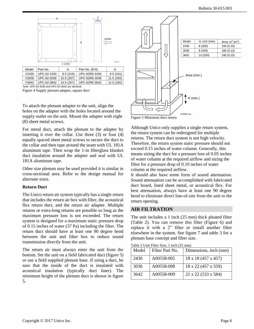
Figure 4 Supply plenum adapter, square duct
To attach the plenum adapter to the unit, align the
holes on the adapter with the holes located around the
supply outlet on the unit. Mount the adapter with eight
(8) sheet metal screws.
For metal duct, attach the plenum to the adapter by
inserting it over the collar. Use three (3) or four (4)
equally spaced sheet metal screws to secure the duct to
the collar and then tape around the seam with UL 181A
aluminum tape. Then wrap the 1-in fiberglass blanket
duct insulation around the adapter and seal with UL
181A aluminum tape.
Other size plenum may be used provided it is similar in
cross-sectional area. Refer to the design manual for
alternate sizes.
Return Duct
The Unico return air system typically has a single return
that includes the return air box with filter, the acoustical
flex return duct, and the return air adapter. Multiple
returns or extra-long returns are possible so long as the
maximum pressure loss is not exceeded. The return
system is designed for a maximum static pressure drop
of 0.15 inches of water (37 Pa) including the filter. The
return duct should have at least one 90 degree bend
between the unit and filter box to reduce sound
transmission directly from the unit.
The return air must always enter the unit from the
bottom. Set the unit on a field fabricated duct (figure 5)
or use a field supplied plenum base. If using a duct, be
sure that the inside of the duct is insulated with
acoustical insulation (typically duct liner). The
minimum height of the plenum duct is shown in figure
5.
Figure 5 Minimum duct return
Although Unico only supplies a single return system,
the return system can be redesigned for multiple
returns. The return duct system is not high velocity.
Therefore, the return system static pressure should not
exceed 0.15 inches of water column. Generally, this
means sizing the duct for a pressure loss of 0.05 inches
of water column at the required airflow and sizing the
filter for a pressure drop of 0.10 inches of water
column at the required airflow.
It should also have some form of sound attenuation.
Sound attenuation can be accomplished with fabricated
duct board, lined sheet metal, or acoustical flex. For
best attenuation, always have at least one 90 degree
bend to eliminate direct line-of-site from the unit to the
return opening.
AIR FILTRATION
The unit includes a 1 inch (25 mm) thick pleated filter
(Table 2). You can remove this filter (Figure 6) and
replace it with a 2” filter or install another filter
elsewhere in the system. See figure 7 and table 3 for a
plenum base concept and filter size.
Table 2 Unit Filter Size, 1 inch (25 mm)
Model Filter Part No. Dimensions, inch (mm)
2430 A00558-005 18 x 18 (457 x 457)
3036 A00558-008 18 x 22 (457 x 559)
3642 A00558-009 21 x 22 (533 x 584)
IL00545.cvx
Part No.
UPC-62-2430
UPC-62-3036
UPC-62-3642
A
8.5 (216)
10.5 (267)
10.5 (267)
Part No. (R-6)
UPC-62R6-2430
UPC-62R6-3036
UPC-62R6-3642
A
9.5 (241)
11.5 (292)
11.5 (292)
Model
V2430
V3036
V3642
Airflow
Note: UPC-62-3036 and UPC-62-3642 are identical.
A
1 (25)
2(52)
A
H (min.)
IL0546.cvx
Model H, inch (mm)
2430 8 (200)
3036 8 (200)
3642 10 (250)
Area, in2 (m2)
150 (0.10)
180 (0.12)
240 (0.15)
Area (min.)
Bulletin 30-015.003
Copyright © 2017 Unico Inc. Page 7
IL00547.cvx
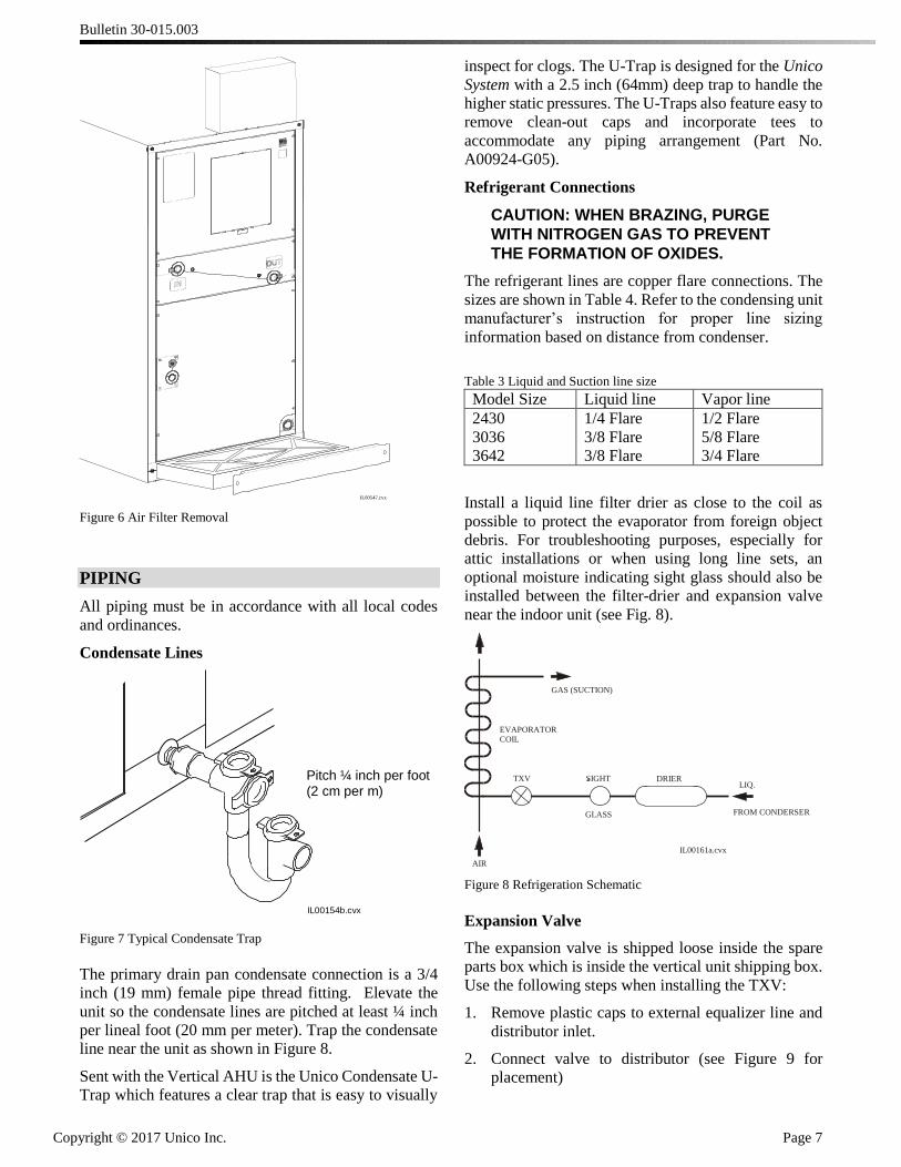
Figure 6 Air Filter Removal
PIPING
All piping must be in accordance with all local codes
and ordinances.
Condensate Lines
Pitch ¼ inch per foot(2 cm per m)
IL00154b.cvx
Figure 7 Typical Condensate Trap
The primary drain pan condensate connection is a 3/4
inch (19 mm) female pipe thread fitting. Elevate the
unit so the condensate lines are pitched at least ¼ inch
per lineal foot (20 mm per meter). Trap the condensate
line near the unit as shown in Figure 8.
Sent with the Vertical AHU is the Unico Condensate U-
Trap which features a clear trap that is easy to visually
inspect for clogs. The U-Trap is designed for the Unico
System with a 2.5 inch (64mm) deep trap to handle the
higher static pressures. The U-Traps also feature easy to
remove clean-out caps and incorporate tees to
accommodate any piping arrangement (Part No.
A00924-G05).
Refrigerant Connections
CAUTION: WHEN BRAZING, PURGE
WITH NITROGEN GAS TO PREVENT
THE FORMATION OF OXIDES.
The refrigerant lines are copper flare connections. The
sizes are shown in Table 4. Refer to the condensing unit
manufacturer’s instruction for proper line sizing
information based on distance from condenser.
Table 3 Liquid and Suction line size
Model Size Liquid line Vapor line
2430
3036
3642
1/4 Flare
3/8 Flare
3/8 Flare
1/2 Flare
5/8 Flare
3/4 Flare
Install a liquid line filter drier as close to the coil as
possible to protect the evaporator from foreign object
debris. For troubleshooting purposes, especially for
attic installations or when using long line sets, an
optional moisture indicating sight glass should also be
installed between the filter-drier and expansion valve
near the indoor unit (see Fig. 8).
IL00161a.cvx
GLASS
SIGHTTXV DRIER
AIR
LIQ.
GAS (SUCTION)
EVAPORATOR
COIL
FROM CONDERSER
Figure 8 Refrigeration Schematic
Expansion Valve
The expansion valve is shipped loose inside the spare
parts box which is inside the vertical unit shipping box.
Use the following steps when installing the TXV:
1. Remove plastic caps to external equalizer line and
distributor inlet.
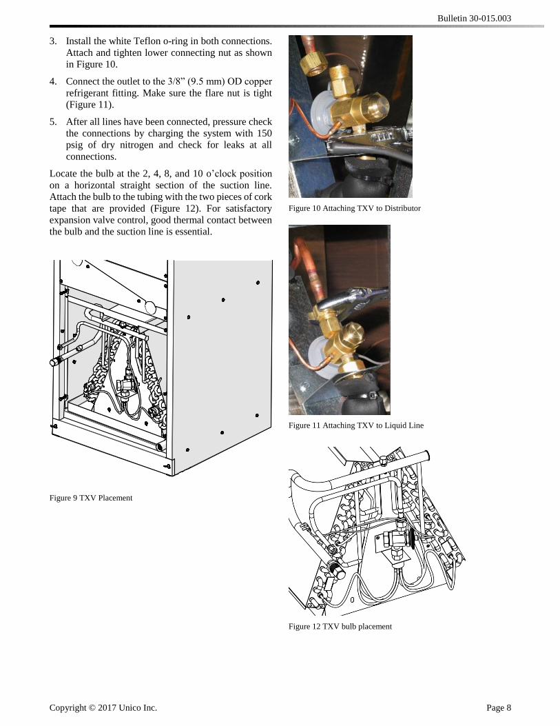
2. Connect valve to distributor (see Figure 9 for
placement)
Bulletin 30-015.003
Copyright © 2017 Unico Inc. Page 8
3. Install the white Teflon o-ring in both connections.
Attach and tighten lower connecting nut as shown
in Figure 10.
4. Connect the outlet to the 3/8” (9.5 mm) OD copper
refrigerant fitting. Make sure the flare nut is tight
(Figure 11).
5. After all lines have been connected, pressure check
the connections by charging the system with 150
psig of dry nitrogen and check for leaks at all
connections.
Locate the bulb at the 2, 4, 8, and 10 o’clock position
on a horizontal straight section of the suction line.
Attach the bulb to the tubing with the two pieces of cork
tape that are provided (Figure 12). For satisfactory
expansion valve control, good thermal contact between
the bulb and the suction line is essential.
Figure 9 TXV Placement
Figure 10 Attaching TXV to Distributor
Figure 11 Attaching TXV to Liquid Line
Figure 12 TXV bulb placement
Bulletin 30-015.003
Copyright © 2017 Unico Inc. Page 9
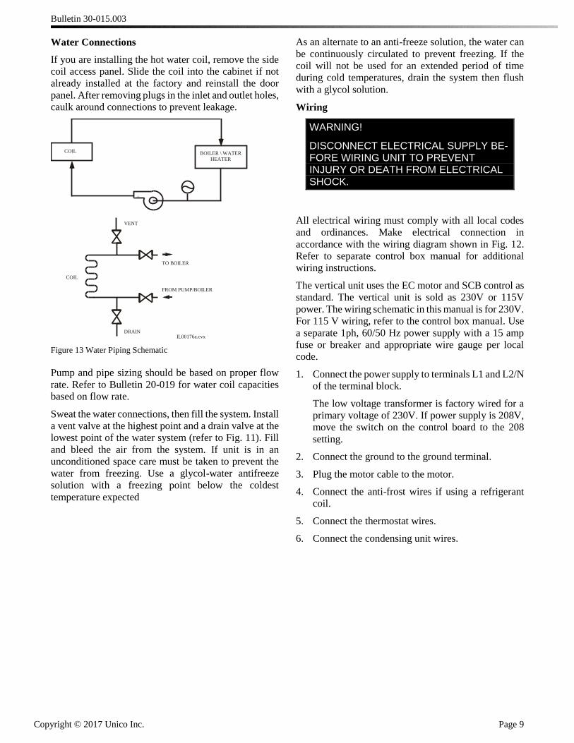
Water Connections
If you are installing the hot water coil, remove the side
coil access panel. Slide the coil into the cabinet if not
already installed at the factory and reinstall the door
panel. After removing plugs in the inlet and outlet holes,
caulk around connections to prevent leakage.
IL00176a.cvx
TO BOILER
COIL
FROM PUMP/BOILER
VENT
DRAIN
COIL BOILER \ WATER
HEATER
Figure 13 Water Piping Schematic
Pump and pipe sizing should be based on proper flow
rate. Refer to Bulletin 20-019 for water coil capacities
based on flow rate.
Sweat the water connections, then fill the system. Install
a vent valve at the highest point and a drain valve at the
lowest point of the water system (refer to Fig. 11). Fill
and bleed the air from the system. If unit is in an
unconditioned space care must be taken to prevent the
water from freezing. Use a glycol-water antifreeze
solution with a freezing point below the coldest
temperature expected
As an alternate to an anti-freeze solution, the water can
be continuously circulated to prevent freezing. If the
coil will not be used for an extended period of time
during cold temperatures, drain the system then flush
with a glycol solution.
Wiring
WARNING!
DISCONNECT ELECTRICAL SUPPLY BE-FORE WIRING UNIT TO PREVENT INJURY OR DEATH FROM ELECTRICAL SHOCK.
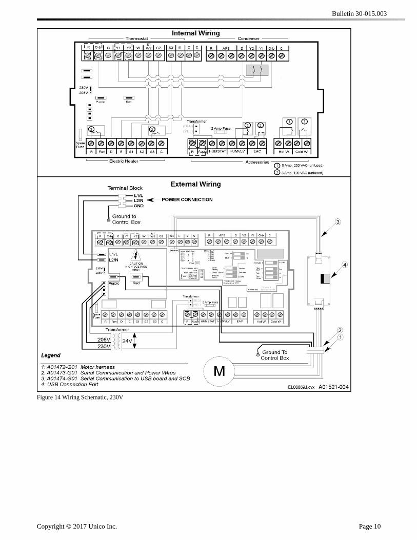
All electrical wiring must comply with all local codes
and ordinances. Make electrical connection in
accordance with the wiring diagram shown in Fig. 12.
Refer to separate control box manual for additional
wiring instructions.
The vertical unit uses the EC motor and SCB control as
standard. The vertical unit is sold as 230V or 115V
power. The wiring schematic in this manual is for 230V.
For 115 V wiring, refer to the control box manual. Use
a separate 1ph, 60/50 Hz power supply with a 15 amp
fuse or breaker and appropriate wire gauge per local
code.
1. Connect the power supply to terminals L1 and L2/N
of the terminal block.
The low voltage transformer is factory wired for a
primary voltage of 230V. If power supply is 208V,
move the switch on the control board to the 208
setting.
2. Connect the ground to the ground terminal.
3. Plug the motor cable to the motor.
4. Connect the anti-frost wires if using a refrigerant
coil.
5. Connect the thermostat wires.
6. Connect the condensing unit wires.
Bulletin 30-015.003
Copyright © 2017 Unico Inc. Page 10
Figure 14 Wiring Schematic, 230V
Bulletin 30-015.003
Copyright © 2017 Unico Inc. Page 11
SEQUENCE OF OPERATION
The sequence of operation depends on the options
installed and type of control thermostat used. Most
thermostats have a fan AUTO-ON switch. When the
fan switch is set to ON, the “G” circuit is closed and
the blower relay is energized. The indoor blower starts
after about a 45 second delay. The following
paragraphs describe the sequence of operation when
the fan is set to AUTO. If the fan switch is set to ON,
the sequence is the same except the “G” circuit is
always closed and the indoor fan is always operating.
Cooling Cycle (A/C or Heat Pump). When the
thermostat calls for cooling, the “Y” and the “G”
circuits are closed, and a 24 V signal is sent to the
compressor contactor in the outdoor unit and fan relay
in the indoor unit. After about 45 seconds, the indoor
blower starts. At the same time, the compressor and
outdoor fan also start. Depending on the control
circuitry in the outdoor unit, there may be a time delay
before the outdoor unit starts. If the system was just
turned off, the time delay could be as much as five
minutes. The cooling system is now operating.
For heat pump thermostats setting the switch to
‘cooling’ immediately closes the “O” circuit, which is
used to energize the reversing valve solenoid if
required by the heat pump. Otherwise, the “B” circuit,
which closes when switched in heating, is used to
energize the reversing valve solenoid. (Refer to the
heat pump manufacturer’s instructions to see which
mode the solenoid needs to be energized – whether in
heating or cooling.)
When the thermostat is satisfied, the 24 V signals open
and the outdoor unit stops. The indoor blower
continues to operate for about 40 seconds, then stops.
The system is now off.
Heating Cycle (Heat Pump). Setting the thermostat
to HEATING will automatically switch the reversing
valve solenoid. This setting closes the “B” circuit
which sends a 24V signal to energize the solenoid if
required by the heat pump. Otherwise the “B” circuit
is not used and the solenoid is not energized during
heating.
When the thermostat calls for heating, the “Y” and “G”
circuits are closed, sending a 24 V signal to the
compressor contactor in the outdoor unit and the fan
relay in the indoor unit. This starts the indoor blower
and the outdoor compressor and blower. There is a
time delay of about 45 seconds for the indoor unit. The
heating system is now operating in stage one.
If the first stage does not satisfy the thermostat, the
second stage thermostat calls for more heat. This
closes the “W2” contacts and energizes the sequencer
for electric heat. When the second stage thermostat is
satisfied, the “W2” circuit is broken and the sequencer
is de-energized. The electric heating system is now off.
When the first stage thermostat is satisfied, the 24 V
signals open and the outdoor unit stops. The indoor
blower continues to operate for about 45 seconds, then
stops. The system is now off.
Heating Cycle (Electric Heat). When the thermostat
calls for heating, the “W2” and “G” circuits are closed.
The W2 circuit completes the 24V signal to the
sequencer in the electric duct heater, which cycles on
the electric heating elements. The heating system is
now operating.
When the thermostat is satisfied, the 24 V signals open
and the indoor blower stops after about 40 seconds. At
the same time the sequencer cuts the power to the
electric elements. The system is now off.
Heating Cycle (Hydronic Heat). When the
thermostat calls for heating, the “W1” circuit brings on
the fan at low speed and “W2” at full speed. The HotW
relay is used to energize either a boiler, valve, or pump.
For ‘combo’ systems, where potable water is
circulated through the hot water heating coil, it is
necessary to ensure that the water is never stagnant in
the coil. The switch will activate a timer so that the
HotW relay will energize a pump to circulate water
once per day for 5 minutes regardless.
If an aquastat is utilized between R and aqua, the fan
relay circuit will remain open until the aquastat is
closed. R-Aqua allows the HotW relay to function
without an optional aquastat. If an aquastat is used, this
jumper must be removed.
When the thermostat is satisfied, the 24 V signal to the
heat relay opens the HotW circuit which stops the
pump or closes a valve. The fan circuit opens and de-
energizes the fan relay. After about 45-seconds the
blower stops.
CHECKING AIRFLOW
CAUTION. DO NOT OPERATE
BLOWER WITH FREE DISCHARGE OR
LOW STATIC PRESSURES (BELOW 1
INCH WC (250 Pa)) TO PREVENT
MOTOR FROM OVERLOADING.
After the system is installed and before charging
system, check for proper airflow. Record the plenum
static pressure. With this information, the amount of
airflow can be determined by counting the flashes on
the SCB.
As a recommended further check on airflow, use the
Turbo-Meter (Davis Instruments Catalog No.
DS105I07) to measure the CFM from each outlet. This
hand held vane type velocity meter that fits directly
Bulletin 30-015.003
Copyright © 2017 Unico Inc. Page 12
over the outlet is the most convenient instrument to
use. The Turbo-Meter will give a direct LED readout
on the KNOTS (FPM x 100) setting, when multiplied
by a simple factor gives the CFM of the outlet within
an accuracy of 10%. Refer to Technote 113 for more
information on use of the Turbo-Meter.
By measuring and totaling the CFM of all outlets and
comparing the total to the SCB readout, one can
determine whether there is gross leakage in the duct
system. If the values are more than 20% or 150 CFM
apart, inspect the duct system for leaks and repair.
Refer to Bulletin 30-039 for checking airflow for an
EC motor.
Static Pressure. Measure the external static pressure
(see figure 13) in the supply plenum at least two feet
(0.6 m) from the unit and verify that it is within the
allowable range.
It is not necessary to measure the return duct static
pressure unless it was field fabricated. The maximum
return static pressure (including filters) should be 0.15
inches of water column (37 Pa). If it is greater than
0.15 inches of water column, add the return system
pressure drop to the supply plenum static pressure to
get the total static pressure drop.
For example: If the supply static pressure is
measured to be 1.6 inches w.c. and the return
system pressure drop is 0.25 inches w.c., the
total static pressure drop is: 1.6 + 0.25 = 1.85.
In this case the static pressure is too high.
How to Measure Static Pressure. Measure the supply
plenum static pressure at least 24 inches (610 mm)
from the unit, but before any tee or elbow. A distance
of between 2 and 3 feet (0.6 to 0.9 m) is best. Use an
inclined manometer capable of reading at least 2.5
inches of water column (622 Pa), such as Dwyer
Instrument’s model 109 manometer. Be sure to zero
the scale and level the manometer. A magnehelic
gauge that measures up to at least 2.5 inches of water
may also be used.
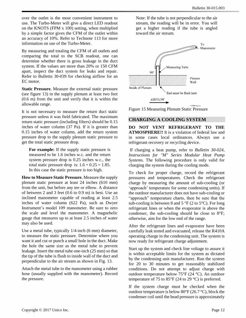
Use a metal tube, typically 1/4-inch (6 mm) diameter,
to measure the static pressure. Determine where you
want it and cut or punch a small hole in the duct. Make
the hole the same size as the metal tube to prevent
leakage. Insert the metal tube one-inch (25 mm) so that
the tip of the tube is flush to inside wall of the duct and
perpendicular to the air stream as shown in Fig. 13.
Attach the metal tube to the manometer using a rubber
hose (usually supplied with the manometer). Record
the pressure.
Note: If the tube is not perpendicular to the air
stream, the reading will be in error. You will
get a higher reading if the tube is angled
toward the air stream.
Figure 15 Measuring Plenum Static Pressure
CHARGING A COOLING SYSTEM
DO NOT VENT REFRIGERANT TO THE
ATMOSPHERE!! It is a violation of federal law and
in some cases local ordinances. Always use a
refrigerant recovery or recycling device.
If charging a heat pump, refer to Bulletin 30-024,
Instructions for "M" Series Modular Heat Pump
Systems. The following procedure is only valid for
charging the system during the cooling mode.
To check for proper charge, record the refrigerant
pressures and temperatures. Check the refrigerant
charge by measuring the amount of sub-cooling (or
‘approach’ temperature for some condensing units). If
the outdoor manufacturer does not have sub-cooling or
“approach” temperature charts, then be sure that the
sub-cooling is between 8 and 5 °F (2 to 5°C). For long
refrigerant lines or when the evaporator is above the
condenser, the sub-cooling should be close to 8°F;
otherwise, aim for the low end of the range.
After the refrigerant lines and evaporator have been
carefully leak tested and evacuated, release the R410A
operating charge in the condensing unit. The system is
now ready for refrigerant charge adjustment.
Start up the system and check line voltage to assure it
is within acceptable limits for the system as dictated
by the condensing unit manufacturer. Run the system
for 20 to 30 minutes to get reasonably stabilized
conditions. Do not attempt to adjust charge with
outdoor temperature below 75°F (24 °C). An outdoor
temperature of 75 to 85°F (24 to 29 °C) is preferred.
If the system charge must be checked when the
outdoor temperature is below 80°F (26.7 °C), block the
condenser coil until the head pressure is approximately
Bulletin 30-015.003
Copyright © 2017 Unico Inc. Page 13
equal to what its charging chart specifies for an 85°F
(29 °C) day.
For heat pumps always check the charge in cooling
mode. If this is not possible because of low outdoor
temperatures, charge the system in the heating mode,
but return later when the weather is warmer before the
system is switched to cooling.
Sub-cooling Method. Many condensing unit
manufacturers publish the amount of sub-cooling that
the condenser will produce. Follow their instructions
to charge the unit. Typical sub-cooling values will be
between 8 and 15°F (5 to 9 °C). The unit should
ALWAYS have some amount of sub-cooling. To be
sure there is enough sub-cooling, especially if the unit
is in a hot attic, check the liquid line sight glass near
the evaporator for bubbles or measure the refrigerant
liquid line pressure and temperature AT THE
EVAPORATOR.
To measure sub-cooling use the following procedure:
1. Measure and record the liquid line pressure using
an accurate refrigerant gauge. Record the
corresponding saturation temperature for this
pressure (see Table 3).
2. Measure and record the liquid line temperature
using an accurate metal or glass thermometer, or
thermocouple. Tape or strap the sensor firmly
against the surface of the liquid line and cover with
insulation.
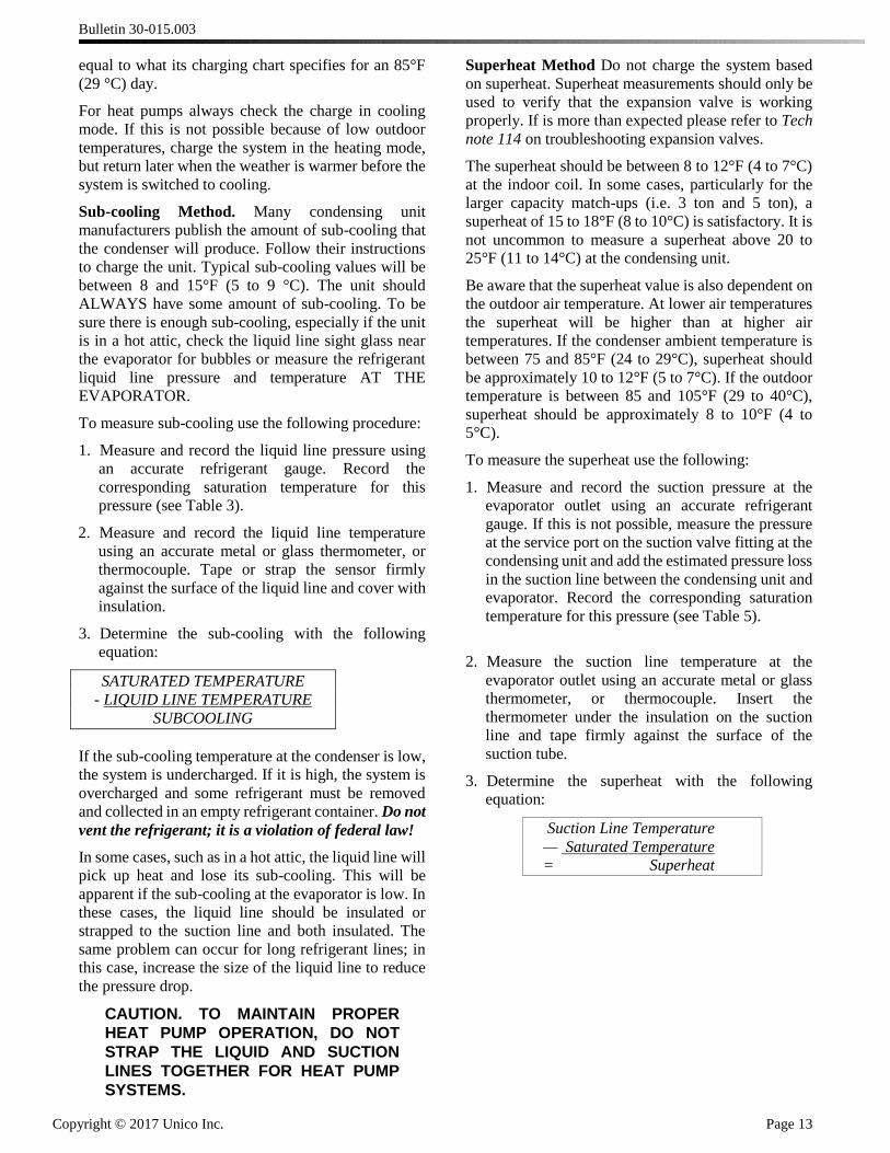
3. Determine the sub-cooling with the following
equation:
SATURATED TEMPERATURE
- LIQUID LINE TEMPERATURE
SUBCOOLING
If the sub-cooling temperature at the condenser is low,
the system is undercharged. If it is high, the system is
overcharged and some refrigerant must be removed
and collected in an empty refrigerant container. Do not
vent the refrigerant; it is a violation of federal law!
In some cases, such as in a hot attic, the liquid line will
pick up heat and lose its sub-cooling. This will be
apparent if the sub-cooling at the evaporator is low. In
these cases, the liquid line should be insulated or
strapped to the suction line and both insulated. The
same problem can occur for long refrigerant lines; in
this case, increase the size of the liquid line to reduce
the pressure drop.
CAUTION. TO MAINTAIN PROPER
HEAT PUMP OPERATION, DO NOT
STRAP THE LIQUID AND SUCTION
LINES TOGETHER FOR HEAT PUMP
SYSTEMS.
Superheat Method Do not charge the system based
on superheat. Superheat measurements should only be
used to verify that the expansion valve is working
properly. If is more than expected please refer to Tech
note 114 on troubleshooting expansion valves.
The superheat should be between 8 to 12°F (4 to 7°C)
at the indoor coil. In some cases, particularly for the
larger capacity match-ups (i.e. 3 ton and 5 ton), a
superheat of 15 to 18°F (8 to 10°C) is satisfactory. It is
not uncommon to measure a superheat above 20 to
25°F (11 to 14°C) at the condensing unit.
Be aware that the superheat value is also dependent on
the outdoor air temperature. At lower air temperatures
the superheat will be higher than at higher air
temperatures. If the condenser ambient temperature is
between 75 and 85°F (24 to 29°C), superheat should
be approximately 10 to 12°F (5 to 7°C). If the outdoor
temperature is between 85 and 105°F (29 to 40°C),
superheat should be approximately 8 to 10°F (4 to
5°C).
To measure the superheat use the following:
1. Measure and record the suction pressure at the
evaporator outlet using an accurate refrigerant
gauge. If this is not possible, measure the pressure
at the service port on the suction valve fitting at the
condensing unit and add the estimated pressure loss
in the suction line between the condensing unit and
evaporator. Record the corresponding saturation
temperature for this pressure (see Table 5).
2. Measure the suction line temperature at the
evaporator outlet using an accurate metal or glass
thermometer, or thermocouple. Insert the
thermometer under the insulation on the suction
line and tape firmly against the surface of the
suction tube.
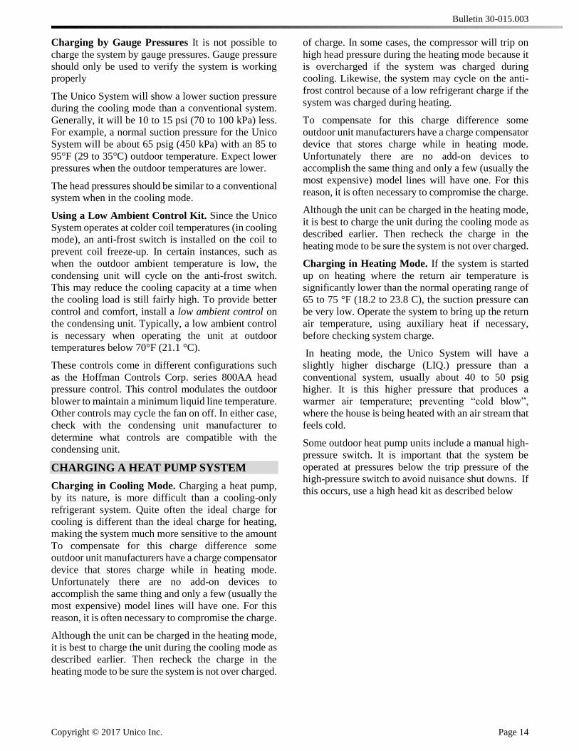
3. Determine the superheat with the following
equation:
Suction Line Temperature
— Saturated Temperature
= Superheat
Bulletin 30-015.003
Copyright © 2017 Unico Inc. Page 14
Charging by Gauge Pressures It is not possible to
charge the system by gauge pressures. Gauge pressure
should only be used to verify the system is working
properly
The Unico System will show a lower suction pressure
during the cooling mode than a conventional system.
Generally, it will be 10 to 15 psi (70 to 100 kPa) less.
For example, a normal suction pressure for the Unico
System will be about 65 psig (450 kPa) with an 85 to
95°F (29 to 35°C) outdoor temperature. Expect lower
pressures when the outdoor temperatures are lower.
The head pressures should be similar to a conventional
system when in the cooling mode.
Using a Low Ambient Control Kit. Since the Unico
System operates at colder coil temperatures (in cooling
mode), an anti-frost switch is installed on the coil to
prevent coil freeze-up. In certain instances, such as
when the outdoor ambient temperature is low, the
condensing unit will cycle on the anti-frost switch.
This may reduce the cooling capacity at a time when
the cooling load is still fairly high. To provide better
control and comfort, install a low ambient control on
the condensing unit. Typically, a low ambient control
is necessary when operating the unit at outdoor
temperatures below 70°F (21.1 °C).
These controls come in different configurations such
as the Hoffman Controls Corp. series 800AA head
pressure control. This control modulates the outdoor
blower to maintain a minimum liquid line temperature.
Other controls may cycle the fan on off. In either case,
check with the condensing unit manufacturer to
determine what controls are compatible with the
condensing unit.
CHARGING A HEAT PUMP SYSTEM
Charging in Cooling Mode. Charging a heat pump,
by its nature, is more difficult than a cooling-only
refrigerant system. Quite often the ideal charge for
cooling is different than the ideal charge for heating,
making the system much more sensitive to the amount
of charge. In some cases, the compressor will trip on
high head pressure during the heating mode because it
is overcharged if the system was charged during
cooling. Likewise, the system may cycle on the anti-
frost control because of a low refrigerant charge if the
system was charged during heating.
To compensate for this charge difference some
outdoor unit manufacturers have a charge compensator
device that stores charge while in heating mode.
Unfortunately there are no add-on devices to
accomplish the same thing and only a few (usually the
most expensive) model lines will have one. For this
reason, it is often necessary to compromise the charge.
Although the unit can be charged in the heating mode,
it is best to charge the unit during the cooling mode as
described earlier. Then recheck the charge in the
heating mode to be sure the system is not over charged.
Charging in Heating Mode. If the system is started
up on heating where the return air temperature is
significantly lower than the normal operating range of
65 to 75 °F (18.2 to 23.8 C), the suction pressure can
be very low. Operate the system to bring up the return
air temperature, using auxiliary heat if necessary,
before checking system charge.
In heating mode, the Unico System will have a
slightly higher discharge (LIQ.) pressure than a
conventional system, usually about 40 to 50 psig
higher. It is this higher pressure that produces a
warmer air temperature; preventing “cold blow”,
where the house is being heated with an air stream that
feels cold.
Some outdoor heat pump units include a manual high-
pressure switch. It is important that the system be
operated at pressures below the trip pressure of the
high-pressure switch to avoid nuisance shut downs. If
this occurs, use a high head kit as described below
To compensate for this charge difference some
outdoor unit manufacturers have a charge compensator
device that stores charge while in heating mode.
Unfortunately there are no add-on devices to
accomplish the same thing and only a few (usually the
most expensive) model lines will have one. For this
reason, it is often necessary to compromise the charge.
Although the unit can be charged in the heating mode,
it is best to charge the unit during the cooling mode as
described earlier. Then recheck the charge in the
heating mode to be sure the system is not over charged.
Bulletin 30-015.003
Copyright © 2017 Unico Inc. Page 15
Using a High Head Kit (Mild Weather Kit). When
any heat pump is operated during mild weather
(temperatures above 50°F (10 C)), the compressor may
trip out on the high pressure limit. The Unico System
is particularly sensitive to this since it operates at a
higher pressure.
To overcome this problem, install a mild weather kit
(UPC-65X) to cycle the outdoor fan based on the
compressor discharge pressure. However, be sure this
control is compatible with the outdoor heat pump
section being used.
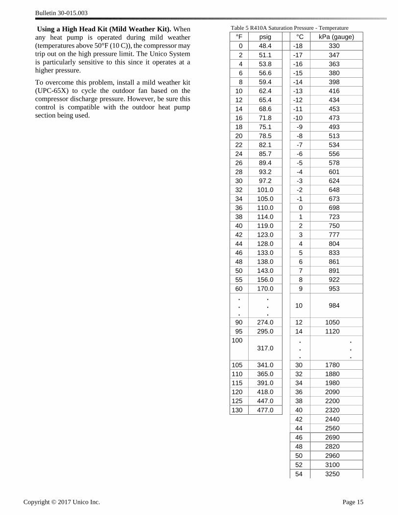
Table 5 R410A Saturation Pressure - Temperature
°F psig °C kPa (gauge)
0 48.4 -18 330
2 51.1 -17 347
4 53.8 -16 363
6 56.6 -15 380
8 59.4 -14 398
10 62.4 -13 416
12 65.4 -12 434
14 68.6 -11 453
16 71.8 -10 473
18 75.1 -9 493
20 78.5 -8 513
22 82.1 -7 534
24 85.7 -6 556
26 89.4 -5 578
28 93.2 -4 601
30 97.2 -3 624
32 101.0 -2 648
34 105.0 -1 673
36 110.0 0 698
38 114.0 1 723
40 119.0 2 750
42 123.0 3 777
44 128.0 4 804
46 133.0 5 833
48 138.0 6 861
50 143.0 7 891
55 156.0 8 922
60 170.0 9 953
.
.
.
.
.
.
10 984
90 274.0 12 1050
95 295.0 14 1120
100
317.0
.
.
.
.
.
.
105 341.0 30 1780
110 365.0 32 1880
115 391.0 34 1980
120 418.0 36 2090
125 447.0 38 2200
130 477.0 40 2320
42 2440
44 2560
46 2690
48 2820
50 2960
52 3100
54 3250


![Interior Vertical Surfacing Installation-Corian[1]](https://img.pdfslide.us/doc/110x75/54780c645906b5aa318b46bf/interior-vertical-surfacing-installation-corian1.jpg)