Embed Size (px)
Citation preview
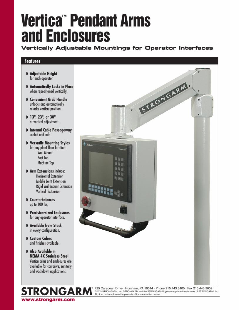
Vertica™ Pendant Arms and Enclosures
Features
Vertically Adjustable Mountings for Operator Interfaces
Adjustable Height for each operator.
Automatically Locks in Place when repositioned vertically.
Convenient Grab Handle unlocks and automatically relocks vertical position.
13", 23", or 30" of vertical adjustment.
Internal Cable Passageway sealed and safe.
Versatile Mounting Styles for any plant floor location: Wall Mount Post Top Machine Top
Arm Extensions include: Horizontal Extension Middle Joint Extension Rigid Wall Mount Extension Vertical Extension
Counterbalances up to 100 lbs.
Precision-sized Enclosures for any operator interface.
Available from Stock in every configuration.
Custom Colors and finishes available.
Also Available in NEMA 4X Stainless Steel Vertica arms and enclosures are available for corrosive, sanitary and washdown applications.
www.strongarm.com
425 Caredean Drive · Horsham, PA 19044 · Phone 215.443.3400 · Fax 215.443.3002©2005 STRONGARM, Inc. STRONGARM and the STRONGARM logo are registered trademarks of STRONGARM, Inc. All other trademarks are the property of their respective owners.
330˚
330˚
330˚
330˚
13"
13"
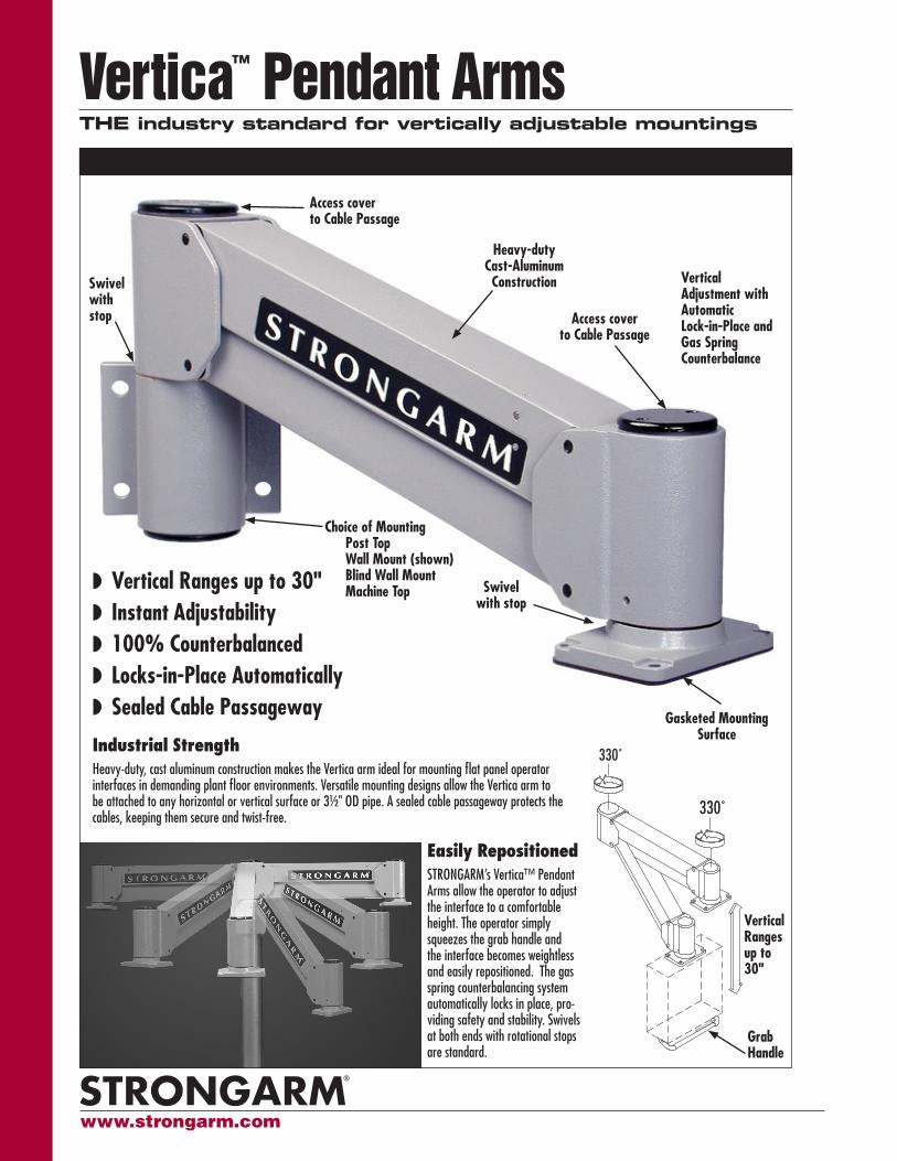
Vertica™ Pendant Arms THE industry standard for vertically adjustable mountings
Gasketed Mounting Surface
Swivel with stop
Access cover to Cable Passage
Vertical Adjustment with Automatic Lock-in-Place and Gas Spring Counterbalance
Heavy-duty Cast-Aluminum Construction
Choice of Mounting Post Top Wall Mount (shown) Blind Wall Mount Machine Top
Industrial StrengthHeavy-duty, cast aluminum construction makes the Vertica arm ideal for mounting flat panel operator interfaces in demanding plant floor environments. Versatile mounting designs allow the Vertica arm to be attached to any horizontal or vertical surface or 3½" OD pipe. A sealed cable passageway protects the cables, keeping them secure and twist-free.
Easily RepositionedSTRONGARM’s Vertica™ Pendant Arms allow the operator to adjust the interface to a comfortable height. The operator simply squeezes the grab handle and the interface becomes weightless and easily repositioned. The gas spring counterbalancing system automatically locks in place, pro-viding safety and stability. Swivels at both ends with rotational stops are standard.
Vertical Ranges up to 30" Instant Adjustability 100% Counterbalanced Locks-in-Place Automatically Sealed Cable Passageway
Access cover to Cable Passage
Swivel with stop
Vertical Ranges up to 30"
Grab Handle
www.strongarm.com
Vertica™ Pendant Arms
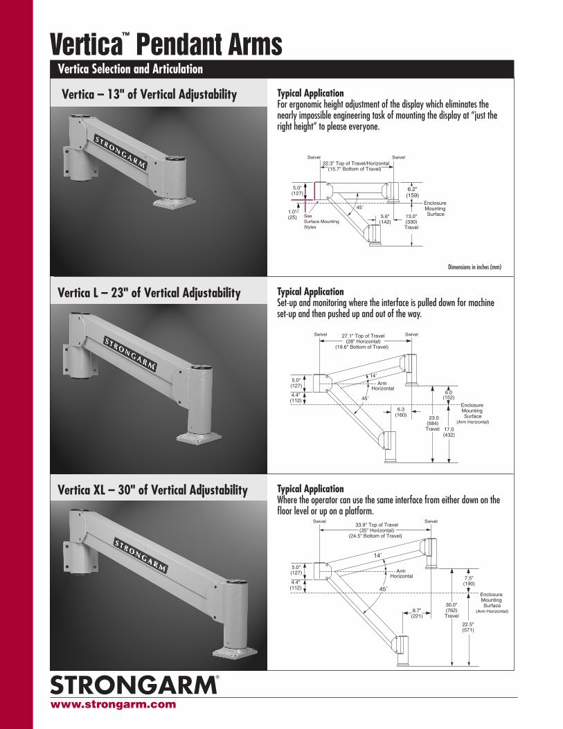
Vertica – 13" of Vertical Adjustability
Vertica XL – 30" of Vertical Adjustability
Vertica L – 23" of Vertical Adjustability
Dimensions in inches (mm)
Vertica Selection and Articulation
Typical Application For ergonomic height adjustment of the display which eliminates the nearly impossible engineering task of mounting the display at “just the right height” to please everyone.
Typical Application Set-up and monitoring where the interface is pulled down for machine set-up and then pushed up and out of the way.
Typical Application Where the operator can use the same interface from either down on the floor level or up on a platform.
5.0" (127)
45˚
14˚
8.7" (221)
30.0" (762) Travel
7.5" (190)
22.5" (571)
33.9" Top of Travel (35" Horizontal)
(24.5" Bottom of Travel)
Swivel Swivel
4.4" (112)
Enclosure Mounting Surface
(Arm Horizontal)
Arm Horizontal
5.0" (127)
45˚
14˚
8.7" (221)
30.0" (762) Travel
7.5" (190)
22.5" (571)
33.9" Top of Travel (35" Horizontal)
(24.5" Bottom of Travel)
Swivel Swivel
4.4" (112)
Enclosure Mounting Surface
(Arm Horizontal)
Arm Horizontal
5.0" (127)
14˚
6.3 (160)
23.0 (584) Travel
6.0 (152)
17.0 (432)
27.1" Top of Travel (28" Horizontal)
(19.6" Bottom of Travel)
Enclosure Mounting Surface
(Arm Horizontal)
45˚
Swivel Swivel
Arm Horizontal
4.4" (112)
5.0" (127)
14˚
6.3 (160)
23.0 (584) Travel
6.0 (152)
17.0 (432)
27.1" Top of Travel (28" Horizontal)
(19.6" Bottom of Travel)
Enclosure Mounting Surface
(Arm Horizontal)
45˚
Swivel Swivel
Arm Horizontal
4.4" (112)
13.0"(330)Travel
6.2"(159)
5.6"(142)
45˚
22.3" Top of Travel/Horizontal(15.7" Bottom of Travel)
See Surface Mounting Styles
1.0"(25)
Enclosure Mounting Surface
5.0"(127)
13.0"(330)Travel
6.2"(159)
5.6"(142)
45˚
22.3" Top of Travel/Horizontal(15.7" Bottom of Travel)
See Surface Mounting Styles
1.0"(25)
Enclosure Mounting Surface
5.0"(127)
Swivel Swivel
www.strongarm.com
2.0"
5.0"
3.54"
Ø 1.4"
(4) Places3.54"
3.6"
5.0"
Ø 0.41for 3/8" bolts
1.38"
5.0"
3.54"
Ø 1.4"
(4) Places3.54"
5.0"
Ø 0.41 for 3/8" bolts
Ø 3.6"Mounting PlateOpening
Ø 3.0"Mounting PlateOpening
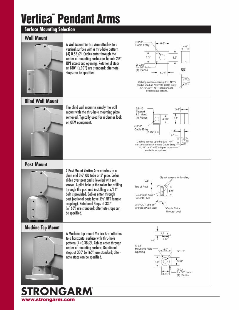
A Post Mount Vertica Arm attaches to a plain end 3½" OD tube or 3" pipe. Collar slides over post and is leveled with set screws. A pilot hole in the collar for drilling through the post and installing a 5/16" bolt is provided. Cables enter through post (optional posts have 1½" NPT female coupling). Rotational Stops at 330º (±165º) are standard; alternate stops can be specified.
A Machine Top mount Vertica Arm attaches to a horizontal surface with thru-hole pattern (4) 0.38 ∅. Cables enter through center of mounting surface. Rotational stops at 330º (±165º) are standard; alter-nate stops can be specified.
Surface Mounting SelectionVertica™ Pendant Arms
3½" OD Tube or 3" Pipe (Plain End)
0.8"
5.0"
Top of Post
(8) set screws for leveling
0.34" pilot hole for 5/16" bolt
Cable Entry through post
3½" OD Tube or 3" Pipe (Plain End)
0.8"
5.0"
Top of Post
(8) set screws for leveling
0.34" pilot hole for 5/16" SS bolt
Cable Entry through post
Wall MountA Wall Mount Vertica Arm attaches to a vertical surface with a thru-hole pattern (4) 0.53 ∅. Cables enter through the center of mounting surface or female 2½" NPT access cap opening. Rotational stops at 180° (±90°) are standard; alternate stops can be specified.
4.0"
5.3"
6.0"
4.75"
3.5"
Ø 0.56" for 3/8" bolts(4) Places
Cable Entry
2.3"
Cabling access opening (2½" NPT) can be used as Alternate Cable Entry.
½", ¾", or 1" NPT adapter caps available as options.
Ø 2.0"
5.3"
6.0"
4.75"
3.5"
Ø 0.53" for ½" bolts(4) Places
Cable EntryØ 2.5"
2.3"
1.8"
3.4"
3/8-16 Tapped1.0" deep (4) Places
∅ 2.0"Cable Entry
4.38"
2.75"
3.6"
5.1"
Cabling access opening (2½" NPT) can be used as Alternate Cable Entry.
½", ¾", or 1" NPT adapter caps available as options.
Machine Top Mount
Post Mount
The blind wall mount is simply the wall mount with the thru-hole mounting plate removed. Typically used for a cleaner look on OEM equipment.
Blind Wall Mount
www.strongarm.com
Vertica™ Pendant ArmsAssembly Configuration Selection
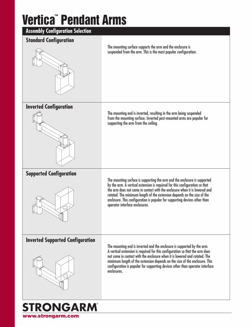
The mounting end is inverted, resulting in the arm being suspended from the mounting surface. Inverted post-mounted arms are popular for supporting the arm from the ceiling.
Inverted Configuration
Inverted Supported Configuration
The mounting surface is supporting the arm and the enclosure is supported by the arm. A vertical extension is required for this configuration so that the arm does not come in contact with the enclosure when it is lowered and rotated. The minimum length of the extension depends on the size of the enclosure. This configuration is popular for supporting devices other than operator interface enclosures.
Supported Configuration
The mounting surface supports the arm and the enclosure is suspended from the arm. This is the most popular configuration.
Standard Configuration
The mounting end is inverted and the enclosure is supported by the arm. A vertical extension is required for this configuration so that the arm does not come in contact with the enclosure when it is lowered and rotated. The minimum length of the extension depends on the size of the enclosure. This configuration is popular for supporting devices other than operator interface enclosures.
www.strongarm.com
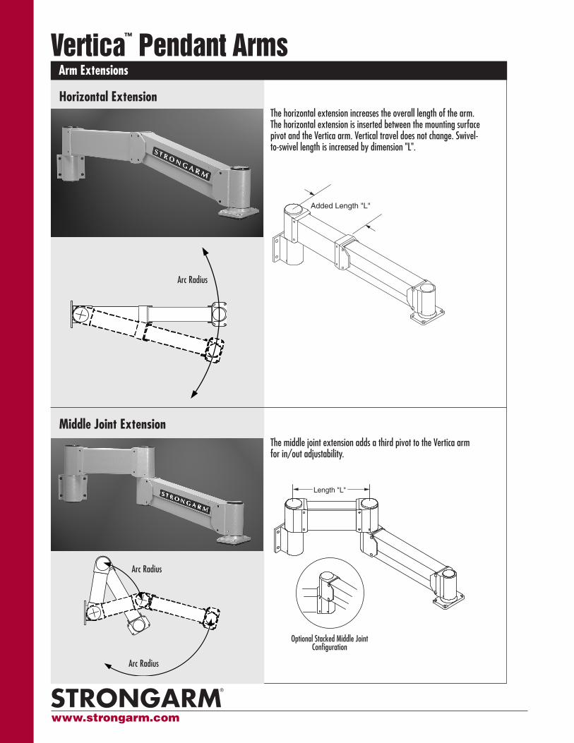
The horizontal extension increases the overall length of the arm. The horizontal extension is inserted between the mounting surface pivot and the Vertica arm. Vertical travel does not change. Swivel-to-swivel length is increased by dimension "L".
Arm ExtensionsVertica™ Pendant Arms
Horizontal Extension
Added Length "L"
Added Length "L"
Added Length "L"
Middle Joint ExtensionThe middle joint extension adds a third pivot to the Vertica arm for in/out adjustability.
Length "L"
Optional Stacked Middle Joint Configuration
Optional Stacked Middle Joint Configuration
Arc Radius
Arc Radius
Arc Radius
www.strongarm.com
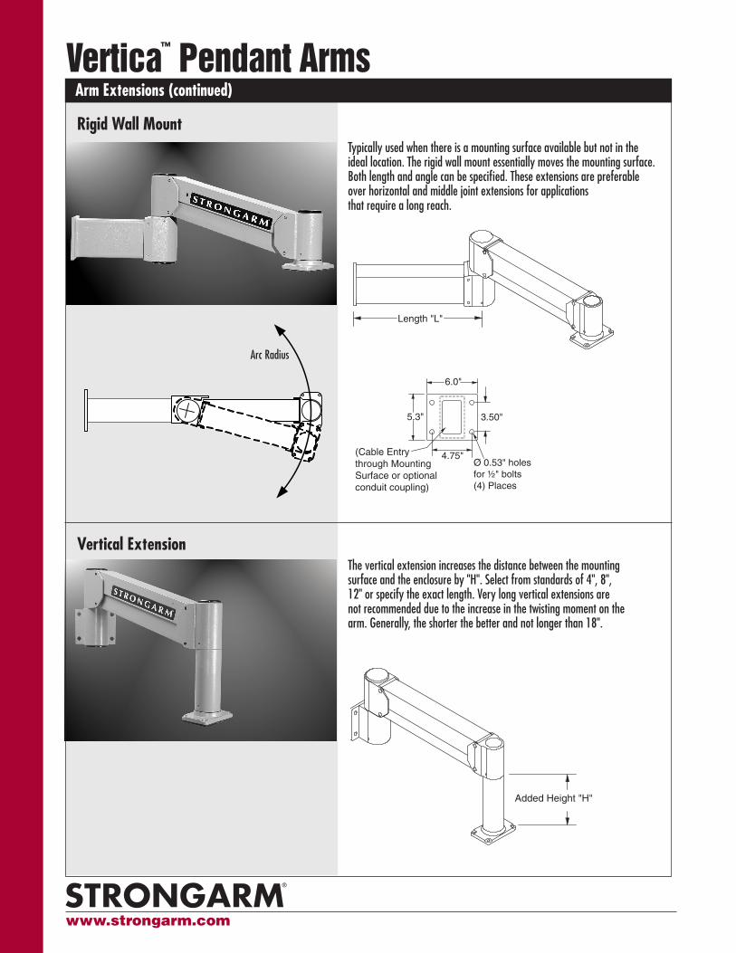
The vertical extension increases the distance between the mounting surface and the enclosure by "H". Select from standards of 4", 8", 12" or specify the exact length. Very long vertical extensions are not recommended due to the increase in the twisting moment on the arm. Generally, the shorter the better and not longer than 18".
Added Height "H"
Added Height "H"
Arm Extensions (continued)Vertica™ Pendant Arms
Vertical Extension
Typically used when there is a mounting surface available but not in the ideal location. The rigid wall mount essentially moves the mounting surface. Both length and angle can be specified. These extensions are preferable over horizontal and middle joint extensions for applications that require a long reach.
Ø 0.53" holesfor ½" bolts(4) Places
5.3"
6.0"
(Cable Entry through Mounting Surface or optional conduit coupling)
3.50"
4.75"
5.3"
6.0"
3.50"
4.75"(Cable Entry through Mounting Surface or optional conduit coupling)
Length "L"
Length "L" Ø 0.53" holesfor ½" bolts(4) Places
Rigid Wall Mount
Arc Radius
Ø 0.53" holesfor ½" bolts(4) Places
5.3"
6.0"
(Cable Entry through Mounting Surface or optional conduit coupling)
3.50"
4.75"
5.3"
6.0"
3.50"
4.75"(Cable Entry through Mounting Surface or optional conduit coupling)
Length "L"
Length "L" Ø 0.53" holesfor ½" bolts(4) Places
www.strongarm.com
Vertica OptionsVertica™ Pendant Arms
Cable Entry
1½" NPT Female coupling for Cable Entry
74"or
79" (79" used for Middle Joint extension)
3½" OD Tube
12.0" 10.0"
12.0"
10.0"∅ 3.0" AlternateCable Entry
1½" NPT Female coupling for Cable Entry
74"or
79" (79" used for Middle Joint extension)
3½" OD Tube
12.0"
12.0"
10.0"
10.0"
Ø 0.56" for 1/2" bolts(4) Places
Ø 0.56" for 1/2" bolts(4) Places
5.0"
5.0"
3.54"
Ø 2.0" Cable Entryor optional coupling
3.54"
5.0"
5.0"
3.54"
Ø 3.0" Cable Entryor optional coupling
3/8-16 1 1/2” long studs (4)
3.54"
36"
36"
Ø 0.56" for 1/2" bolts(4) Places
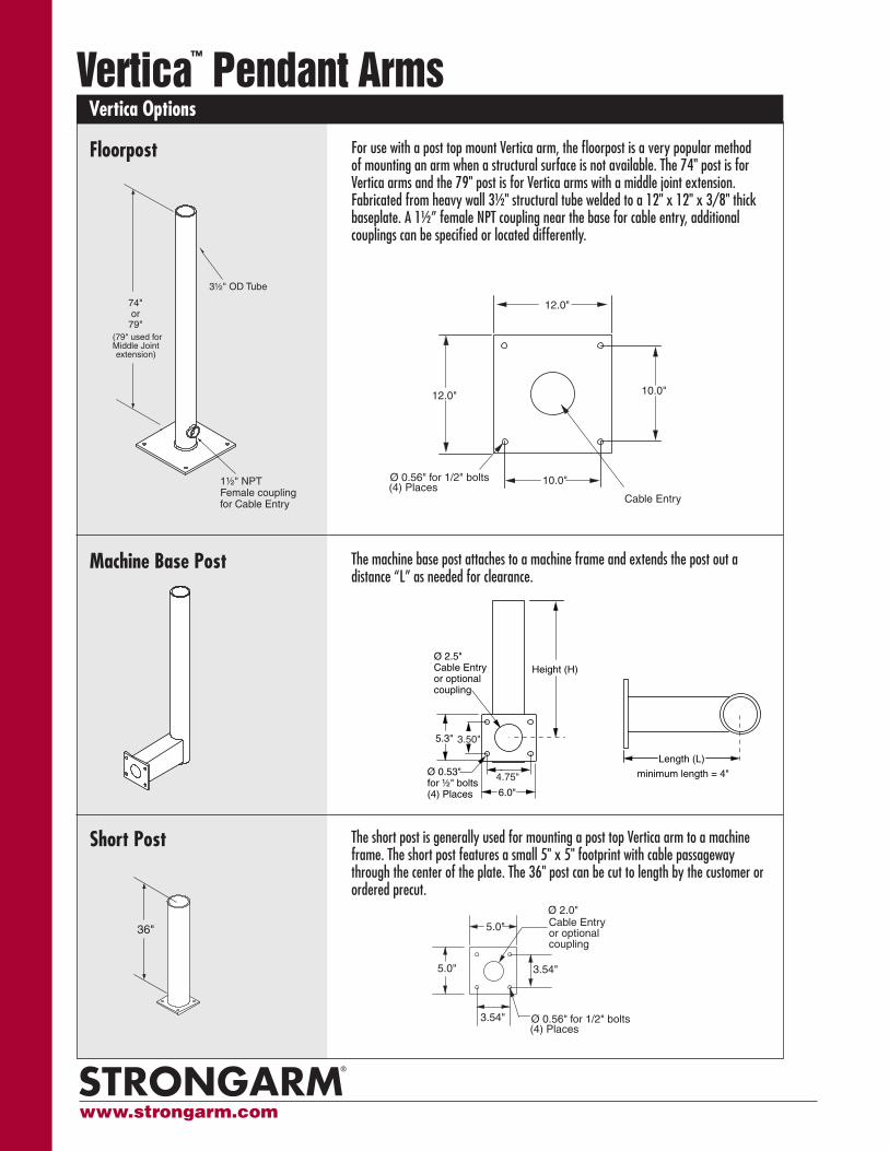
For use with a post top mount Vertica arm, the floorpost is a very popular method of mounting an arm when a structural surface is not available. The 74" post is for Vertica arms and the 79" post is for Vertica arms with a middle joint extension. Fabricated from heavy wall 3½" structural tube welded to a 12" x 12" x 3/8" thick baseplate. A 1½” female NPT coupling near the base for cable entry, additional couplings can be specified or located differently.
The short post is generally used for mounting a post top Vertica arm to a machine frame. The short post features a small 5" x 5" footprint with cable passageway through the center of the plate. The 36" post can be cut to length by the customer or ordered precut.
Floorpost
Short Post
5.0"
5.0"
3.54"
Ø 2.0" Cable Entryor optional coupling
3.54"
5.0"
5.0"
3.54"
Ø 3.0" Cable Entryor optional coupling
3/8-16 1 1/2” long studs (4)
3.54"
36"
36"
Ø 0.56" for 1/2" bolts(4) Places
Height (H)
Length (L)
minimum length = 4"
5.3" 3.50"
6.0"
4.75"
Ø 2.5"Cable Entryor optional coupling
Ø 0.53" for ½" bolts(4) Places
The machine base post attaches to a machine frame and extends the post out a distance “L” as needed for clearance.
Machine Base Post
Height (H)
Length (L)
minimum length = 4"
5.3" 3.50"
6.0"
4.75"
Ø 2.5"Cable Entryor optional coupling
Ø 0.53" for ½" bolts(4) Places
Cable Entry
1½" NPT Female coupling for Cable Entry
74"or
79" (79" used for Middle Joint extension)
3½" OD Tube
12.0" 10.0"
12.0"
10.0"∅ 3.0" AlternateCable Entry
1½" NPT Female coupling for Cable Entry
74"or
79" (79" used for Middle Joint extension)
3½" OD Tube
12.0"
12.0"
10.0"
10.0"
Ø 0.56" for 1/2" bolts(4) Places
Ø 0.56" for 1/2" bolts(4) Places
www.strongarm.com
Vertica Options (continued)Vertica™ Pendant Arms
Floorpost Accessories
Tie-off Kit for Inverted Post A popular method of mounting is to invert a floorpost and attach it to a ceiling structure. To avoid twisting of the structure, it is recommended that diagonal tie-offs are installed. This kit includes (2) sets of clamps that attach to the post and have thru-holes for attaching user-supplied tie-offs between the clamps and ceiling structure.
Freestanding Floorplate Heavy ¼-thick, reinforced plate used to freestand a floorpost mounted system. Intended for temporary Vertica installations, including training rooms, development labs and trade shows. For Vertica L or XL, specify Freestanding Floorplate with Outriggers.
Release Handles
Enclosure Handle Standard enclosure handle is supplied with the Vertica Arm. See Vertica Specifications.
Arm Handle The arm handle is attached to the Vertica arm and used for non-enclosure or other unusual applications where the standard handle is inappropriate.
Rotational StopsSpecified Rotational Stops Alternative rotational stop locations can be specified. The standard default stop locations are listed in Vertica
Specifications. Use the same format when specifying the limits of the desired rotation.
Latching Stop The latching stop holds the swivel point at an exact angle. The stop is released by a short pull lever located on the front side of the arm end. The stop pin is spring-loaded for automatic latching. Hard stops are also installed to prevent rotation beyond the latching stop, please call for assistance.
Detent Stop Detent stops hold the swivel point at an exact position and releases when a firm force is applied. Detents utilize spring ball mechanisms and have adjustable breakaway force. Detent stops are application specific, please call for assistance.
Finish
Alternate Paint Finishes Powder Coat: Black, White Polyurethane paint: Black, White, Stone Gray RAL 7030 Steel-it stainless steel based paint: Natural steel-it gray color
Color Matching Colors can be matched in Polyurethane paint to customer-supplied sample.
Other OptionsField-setTM Adjustable The patented field-set system permits adjustment of the gas springs pressure by the installer. As shipped, the springs Counterbalance are set to maximum pressure. After installation, the user can reduce the lifting force of arm.
Restricted Vertical Travel The angle of travel can be restricted as necessary, specify angle(s).
Clean Room Specification Specific to semiconductor manufacturers, this option reduces the bearing surface materials to just stainless steel on Delrin (acetal). Also, the use of all lubricants is eliminated. Available for loads less than 100 ft/lbs.
Threaded Access Caps The cable access covers can be supplied with a ½” NPT female thread for mounting a stack light.
Support Tray Typically used in a supported assembly configuration for holding non-operator interfaces.
www.strongarm.com
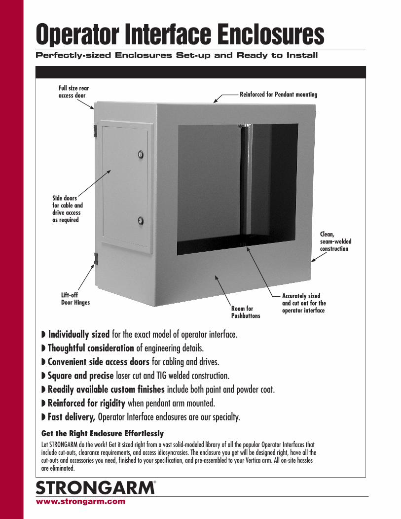
Operator Interface Enclosures Perfectly-sized Enclosures Set-up and Ready to Install
Get the Right Enclosure EffortlesslyLet STRONGARM do the work! Get it sized right from a vast solid-modeled library of all the popular Operator Interfaces that include cut-outs, clearance requirements, and access idiosyncrasies. The enclosure you get will be designed right, have all the cut-outs and accessories you need, finished to your specification, and pre-assembled to your Vertica arm. All on-site hassles are eliminated.
Individually sized for the exact model of operator interface. Thoughtful consideration of engineering details. Convenient side access doors for cabling and drives. Square and precise laser cut and TIG welded construction. Readily available custom finishes include both paint and powder coat. Reinforced for rigidity when pendant arm mounted. Fast delivery, Operator Interface enclosures are our specialty.
Reinforced for Pendant mounting
Room for Pushbuttons
Accurately sized and cut out for the operator interface
Clean, seam-welded construction
Side doors for cable and drive access as required
Full size rear access door
Lift-off Door Hinges
www.strongarm.com
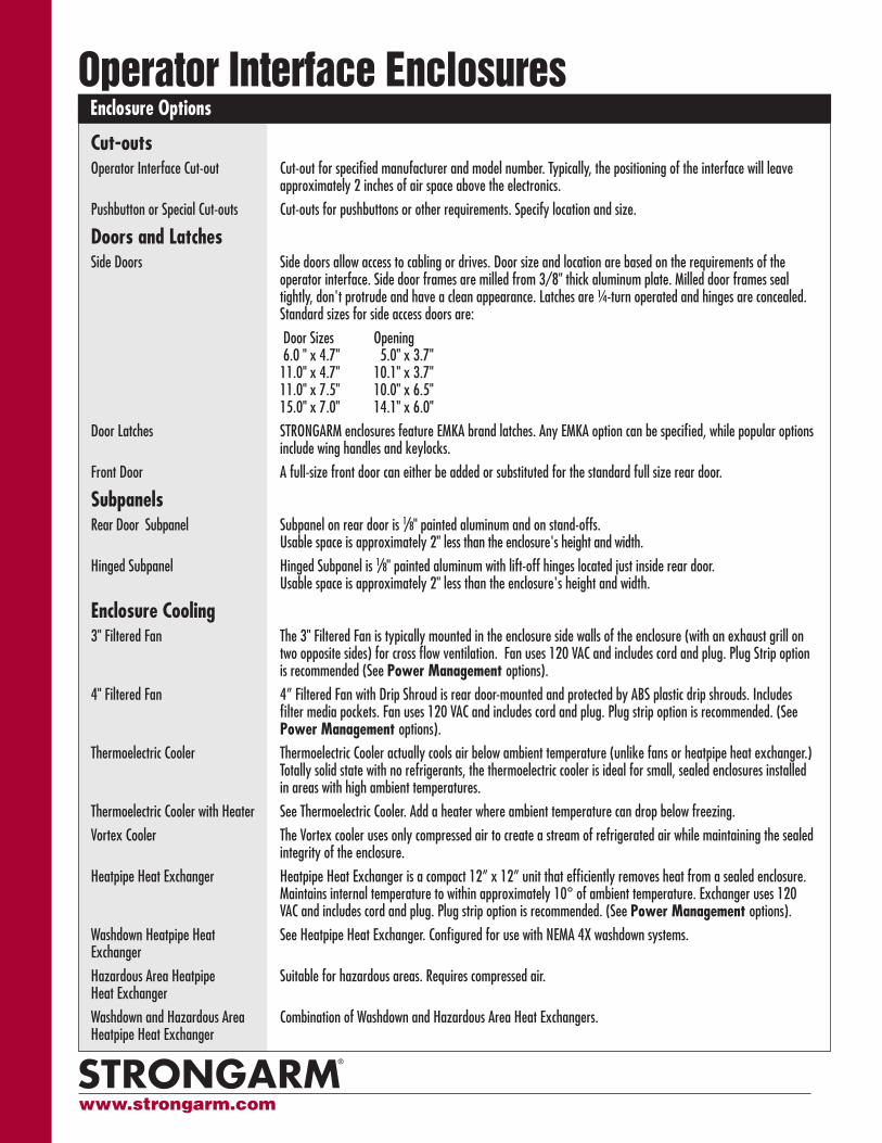
Enclosure Options Operator Interface Enclosures
Cut-outsOperator Interface Cut-out Cut-out for specified manufacturer and model number. Typically, the positioning of the interface will leave
approximately 2 inches of air space above the electronics.
Pushbutton or Special Cut-outs Cut-outs for pushbuttons or other requirements. Specify location and size.
Doors and LatchesSide Doors Side doors allow access to cabling or drives. Door size and location are based on the requirements of the
operator interface. Side door frames are milled from 3/8" thick aluminum plate. Milled door frames seal tightly, don't protrude and have a clean appearance. Latches are ¼-turn operated and hinges are concealed. Standard sizes for side access doors are:
Door Sizes Opening 6.0 " x 4.7" 5.0" x 3.7" 11.0" x 4.7" 10.1" x 3.7" 11.0" x 7.5" 10.0" x 6.5" 15.0" x 7.0" 14.1" x 6.0"
Door Latches STRONGARM enclosures feature EMKA brand latches. Any EMKA option can be specified, while popular options include wing handles and keylocks.
Front Door A full-size front door can either be added or substituted for the standard full size rear door.
SubpanelsRear Door Subpanel Subpanel on rear door is 1/8" painted aluminum and on stand-offs.
Usable space is approximately 2" less than the enclosure's height and width.
Hinged Subpanel Hinged Subpanel is 1/8" painted aluminum with lift-off hinges located just inside rear door. Usable space is approximately 2" less than the enclosure's height and width.
Enclosure Cooling3" Filtered Fan The 3" Filtered Fan is typically mounted in the enclosure side walls of the enclosure (with an exhaust grill on
two opposite sides) for cross flow ventilation. Fan uses 120 VAC and includes cord and plug. Plug Strip option is recommended (See Power Management options).
4" Filtered Fan 4” Filtered Fan with Drip Shroud is rear door-mounted and protected by ABS plastic drip shrouds. Includes filter media pockets. Fan uses 120 VAC and includes cord and plug. Plug strip option is recommended. (See Power Management options).
Thermoelectric Cooler Thermoelectric Cooler actually cools air below ambient temperature (unlike fans or heatpipe heat exchanger.) Totally solid state with no refrigerants, the thermoelectric cooler is ideal for small, sealed enclosures installed in areas with high ambient temperatures.
Thermoelectric Cooler with Heater See Thermoelectric Cooler. Add a heater where ambient temperature can drop below freezing.
Vortex Cooler The Vortex cooler uses only compressed air to create a stream of refrigerated air while maintaining the sealed integrity of the enclosure.
Heatpipe Heat Exchanger Heatpipe Heat Exchanger is a compact 12” x 12” unit that efficiently removes heat from a sealed enclosure. Maintains internal temperature to within approximately 10° of ambient temperature. Exchanger uses 120 VAC and includes cord and plug. Plug strip option is recommended. (See Power Management options).
Washdown Heatpipe Heat See Heatpipe Heat Exchanger. Configured for use with NEMA 4X washdown systems. Exchanger
Hazardous Area Heatpipe Suitable for hazardous areas. Requires compressed air.Heat Exchanger
Washdown and Hazardous Area Combination of Washdown and Hazardous Area Heat Exchangers.Heatpipe Heat Exchanger
www.strongarm.com
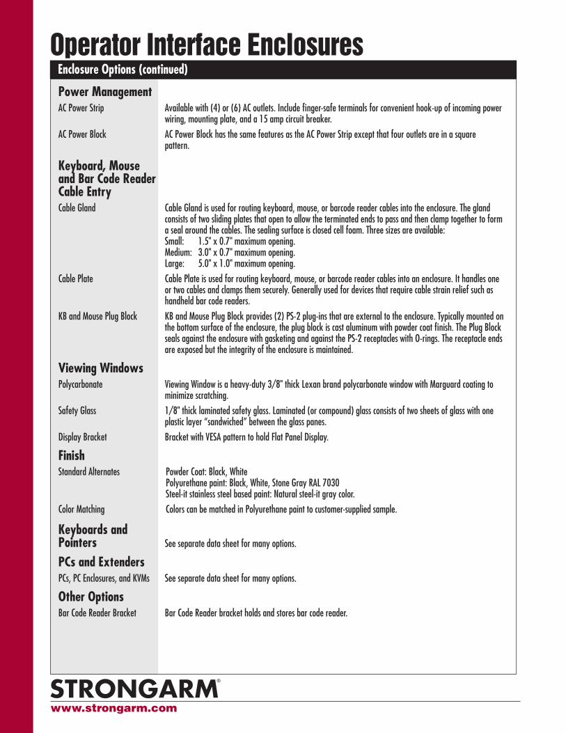
Enclosure Options (continued) Operator Interface Enclosures
Power ManagementAC Power Strip Available with (4) or (6) AC outlets. Include finger-safe terminals for convenient hook-up of incoming power
wiring, mounting plate, and a 15 amp circuit breaker.
AC Power Block AC Power Block has the same features as the AC Power Strip except that four outlets are in a square pattern.
Keyboard, Mouse and Bar Code Reader Cable EntryCable Gland Cable Gland is used for routing keyboard, mouse, or barcode reader cables into the enclosure. The gland
consists of two sliding plates that open to allow the terminated ends to pass and then clamp together to form a seal around the cables. The sealing surface is closed cell foam. Three sizes are available:
Small: 1.5" x 0.7" maximum opening. Medium: 3.0" x 0.7" maximum opening. Large: 5.0" x 1.0" maximum opening.
Cable Plate Cable Plate is used for routing keyboard, mouse, or barcode reader cables into an enclosure. It handles one or two cables and clamps them securely. Generally used for devices that require cable strain relief such as handheld bar code readers.
KB and Mouse Plug Block KB and Mouse Plug Block provides (2) PS-2 plug-ins that are external to the enclosure. Typically mounted on the bottom surface of the enclosure, the plug block is cast aluminum with powder coat finish. The Plug Block seals against the enclosure with gasketing and against the PS-2 receptacles with O-rings. The receptacle ends are exposed but the integrity of the enclosure is maintained.
Viewing WindowsPolycarbonate Viewing Window is a heavy-duty 3/8" thick Lexan brand polycarbonate window with Marguard coating to
minimize scratching.
Safety Glass 1/8" thick laminated safety glass. Laminated (or compound) glass consists of two sheets of glass with one plastic layer “sandwiched” between the glass panes.
Display Bracket Bracket with VESA pattern to hold Flat Panel Display.
Finish Standard Alternates Powder Coat: Black, White Polyurethane paint: Black, White, Stone Gray RAL 7030 Steel-it stainless steel based paint: Natural steel-it gray color.
Color Matching Colors can be matched in Polyurethane paint to customer-supplied sample.
Keyboards and Pointers See separate data sheet for many options.
PCs and Extenders PCs, PC Enclosures, and KVMs See separate data sheet for many options.
Other Options Bar Code Reader Bracket Bar Code Reader bracket holds and stores bar code reader.
www.strongarm.com
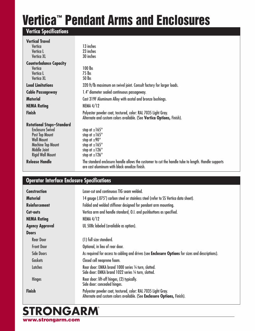
Construction Laser-cut and continuous TIG seam welded.
Material 14 gauge (.075") carbon steel or stainless steel (refer to SS Vertica data sheet).
Reinforcement Folded and welded stiffener designed for pendant arm mounting.
Cut-outs Vertica arm and handle standard, O.I. and pushbuttons as specified.
NEMA Rating NEMA 4/12
Agency Approval UL 508c labeled (available as option).
DoorsRear Door (1) full size standard.
Front Door Optional, in lieu of rear door.
Side Doors As required for access to cabling and drives (see Enclosure Options for sizes and descriptions).
Gaskets Closed cell neoprene foam.
Latches Rear door: EMKA brand 1000 series ¼ turn, slotted. Side door: EMKA brand 1022 series ¼ turn, slotted.
Hinges Rear door: lift-off hinges, (2) typically. Side door: concealed hinges.
Finish Polyester powder coat, textured, color: RAL 7035 Light Gray. Alternate and custom colors available. (See Enclosure Options, Finish).
Vertica™ Pendant Arms and EnclosuresVertica Specifications
Operator Interface Enclosure Specifications
Vertical TravelVertica 13 inches Vertica L 23 inches Vertica XL 30 inches
Counterbalance CapacityVertica 100 lbs Vertica L 75 lbs Vertica XL 50 lbs
Load Limitations 320 ft/lb maximum on swivel joint. Consult factory for larger loads.
Cable Passageway 1.4" diameter sealed continuous passageway.
Material Cast 319F Aluminum Alloy with acetal and bronze bushings.
NEMA Rating NEMA 4/12
Finish Polyester powder coat, textured, color: RAL 7035 Light Gray. Alternate and custom colors available. (See Vertica Options, Finish).
Rotational Stops–StandardEnclosure Swivel stop at ±165° Post Top Mount stop at ±165°Wall Mount stop at ±90° Machine Top Mount stop at ±165° Middle Joint stop at ±126° Rigid Wall Mount stop at ±126°
Release Handle The standard enclosure handle allows the customer to cut the handle tube to length. Handle supports are cast aluminum with black anodize finish.
www.strongarm.com
Printed in USA. Publication 104391
Series502 Vertica Arm and Enclosure
Vertica Arm502 - V 13” vertical travel502 - L 23” vertical travel502 - X 30” vertical travel
Surface Mounting 502 - P Post Top Mount502 - W Wall Mount502 - B Blind Wall Mount502 - M Machine Top Mount
Assembly Configuration502 - 1 Standard Configuration 502 - 2 Inverted Configuration 502 - 3 Supported Configuration 502 - 4 Inverted/Supported Configuration
Arm Extensions502 - Hxx Horizontal Extension in specified xx length (inches)502 - Mxx Middle Joint Extension in specified xx length (16, 24, or 36 inches standard)502 - Rxx Rigid wall mount in specified xx length (inches)502 - Vxx Vertical Extension in specified xx length (4, 8, or 12 inches standard)502 - MXT Multiple Extensions. Type and length of multiple extensions listed in unique serial
number. See Options.502 - 000 No extensions
Enclosure502 - - HHWWDD Height, Width, Depth of Enclosure
Options502 - - - xxxxx Select options from Vertica options and Enclosures options lists.
(xxxxx represents unique serial number that is assigned at order entry)
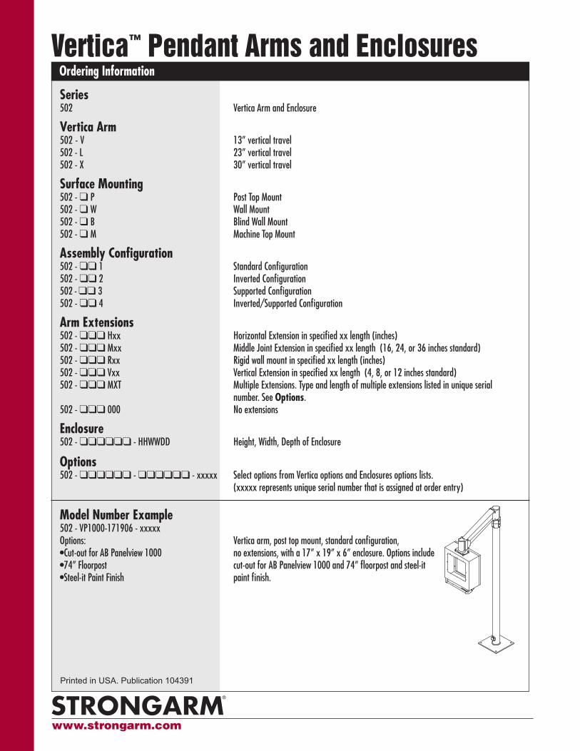
Model Number Example 502 - VP1000-171906 - xxxxxOptions: Vertica arm, post top mount, standard configuration, •Cut-out for AB Panelview 1000 no extensions, with a 17” x 19” x 6” enclosure. Options include •74” Floorpost cut-out for AB Panelview 1000 and 74” floorpost and steel-it •Steel-it Paint Finish paint finish.
Vertica™ Pendant Arms and EnclosuresOrdering Information
www.strongarm.com