Embed Size (px)
Citation preview

Chapter 11
VERSION 6.4S (Second-ordermodule)
WAMIT Version 6.4S designates a program which extends the capabilities of WAMITVersion 6.4 to include the analysis of the second-order hydrodynamic interaction betweenwaves and one or more structures. V6.4S has all of the capabilities of V6.4, with the ex-ceptions listed below. The extended capabilities of V6.4S include evaluation of the sum-and difference-frequency components of the second-order forces and moments (QuadraticTransfer Functions, or QTF), the second-order hydrodynamic pressure on the body andin the fluid domain, the second-order wave elevation and the second-order Response Am-plitude Operator (RAO), in the presence of bichromatic and bidirectional waves. Thesecond-order forces 1 can be evaluated by both indirect and direct methods, analogousto the linear forces evaluated from Haskind relations and from diffraction pressure. Thestructures can be freely floating, submerged, constrained or fixed.
The second-order solutions are not available in the situations listed below: i) the generalizedmode (NEWMDS) option is not allowed, ii) fixed/free modes option is not allowed, iii)walls are not allowed and iv) the zero-thickness structure is not allowed. The effect ofthe external constraints can be accounted for partially when the second-order RAO isevaluated. Specifically, only the effect of the constraints which is linearly proportional tothe second-order motion RAO can be accounted for using the external force matrices ofthe Alternative 2 format of the FRC file. Quadratic terms which include the effect of theconstraints due to the linear RAO are not included.
The major updates in V6.4S from the previous version, V6.1S, are as follow.
1. Second-order analysis can be made for vessels with internal tanks with free surfaces.
2. The method using control surfaces, implemented for the evaluation of the mean driftforces, is extended for the evaluation of the quadratic forces. Using this option, thequadratic forces may be evaluated more accurately than using the conventional pressureintegration.
1It is understood forces include both forces and moments throughout this chapter.
11–1

3. In V6.1S, when ILOWHI=1, the second-order forcing terms are evaluated on the cen-troids of flat panels approximating the body and free surfaces. In V6.4S, they are evaluatedon the centroids of subdivided areas on the exact body and free surfaces without approxi-mation.
4. Various options of geometry definitions can be used to describe the free surface geometry.
5. V6.4S is compiled using Intel Fortran V12.1. It is available in a 64-bit executable form,eliminating the limit of the usage of RAM inherent in 32-bit Windows applications.
The rest of this chapter describes the input and output of V6.4S which differ from thoseof V6.4. It is recommended to review the previous chapters, if users are not familiar withV6.4. The description of the theoretical background of the second-order analysis can befound in References [9], [17], [26] and other documents cited therein.
All input files for V6.4 are required in order to run V6.4S. These include CFG, GDF,POT, FRC, optional FNAMES.WAM as well as optional SPL when ILOWHI=1. Thesefiles can be used without modifications, when the linear quantities and mean drift forceare evaluated. To evaluate the second-order quantities, new parameters must be added tothe CFG (or CONFIG.WAM) and FRC files. In addition, up to three new files must beprepared. These are the Potential Control File 2 (PT2), the Free Surface Geometry DataFile (FDF) and the Spline Control File (FDF.SPL). Extensions, .pt2, .fdf and fdf.spl arereserved for these three additional input files. The filename of FDF.SPL should be the sameas the corresponding FDF filename. For example, for a FDF file with the complete filenameexample.fdf, the corresponding FDF.SPL file should be named as example fdf.spl. Thefilenames of PT2 and FDF, including the extentions, may be specified in FNAMES.WAM,in order to avoid interactive input of these filenames during execution of WAMIT.
New parameters in the CFG and FRC files and the parameters in the new input files aredescribed next.
11.1 THE CONFIGURATION FILE (CFG)
The parameter I2ND must be specified to evaluate the second-order solution.
I2ND=0: Do not compute the second-order solution (0 is the default value).
I2ND=1: Compute the second-order solution for the sum- and difference-frequencies listedin the PT2 file.
When I2ND=1, the dimension of the NOOUT array parameter in the CFG file mustbe increased from 9 to 16. The last 7 indices, between 10 and 16, correspond to sevensecond-order quantities described in the next section. For example, by specifying
NOOUT=1 1 1 1 0 1 1 1 1 1 1 1 0 1 1 1
all available linear and second-order quantities are output in the OUT file except options5 and 13 which correspond to the linear and the second-order pressure and velocity on thebody surface.
11–2

ISOR=1 must be specified, when ILOWHI=0 and I2ND=1. Otherwise, execution of theprogram is aborted with an appropriate error message.
NPTANKFS is an integer array specifying indices of the panels or patches on the free sur-face over each internal tank. This parameter is specified in the same manner as NPTANK(see Sections 3.7 and 10.7). Thus the data in this array are in pairs, denoting the firstand last index of the panels or patches on the tanks. If NBODY>1, the body number ofeach body which contains internal tanks must be appended to the parameter name suchas NPTANKFS(IB), where IB is the body index.
11.2 THE FORCE CONTROL FILE (FRC)
The input parameters in the FRC files are described in Chapters 3 and 8. For the secondanalysis, the dimension of the array IOPTN, on the second line of the FRC files, should beincreased to 16 from 9. The last 7 elements of the IOPTN array correspond to second-orderhydrodynamic parameters.
The first two lines of the FRC file are shown below.
header
IOPTN(1)...IOPTN(9)IOPTN(10)IOPTN(11)IOPTN(12)...IOPTN(16)
.
.
The IOPTN array can be specified on one line or on multiple lines without space betweenthe lines. When I2ND=0, only the first 9 elements are read in the program and it is notnecessary to specify the last 7 elements. If all 16 elements are specified with 0 for the last7 elements, the last 7 elements must be on the same line with IOPTN(9).
Descriptions of the output options and numeric file names for I=10,....,16 are as follows(Descriptions of the output options, corresponding to IOPTN(I) for I=1,....,9, can be foundin Section 3.3.):
Option Description File name
10 Quadratic second-order forces by pressure integration frc.10s, frc.10d10 Quadratic second-order forces by control surface integration frc.qcs, frc.qcd11 Total second-order forces by indirect method frc.11s, frc.11d12 Total second-order forces by direct method frc.12s, frc.12d13 Second-order hydrodynamic pressure on the body frc.13s, frc.13d14 Second-order hydrodynamic pressure in the fluid frc.14s, frc.14d15 Second-order wave elevation frc.15s, frc.15d16 Second-order response amplitude operator frc.16s, frc.16d
11–3

The last letters, ‘s’ and ‘d’, of the numeric filenames signify that the files contain the outputfor sum-frequencies and difference-frequencies, respectively.
The evaluation and output of the above quantities are in accordance with the followingchoice of the corresponding index:
IOPTN(I) = 0 : do not output parameters associated with option I.
IOPTN(I) = 1 : do output parameters associated with option I.
IOPTN(16) may have an additional value as listed below:
IOPTN(16) = 0 : do not output the second-order RAO.
IOPTN(16) = 1 : do output the second-order RAO computed using the ‘indirect’ excitingforce.
IOPTN(16) = 2 : do output the second-order RAO computed using the ‘direct’ excitingforce.
When IOPTN(10)=1 and ICTRSURF=0, the quadratic forces are evaluated by directpressure integration only. The corresponding numeric output files are .10s and .10d. WhenIOPTN(10)=1 and ICTRSURF=1, the quadratic forces are evaluated by control surfaceintegration in addition to pressure integration. These forces are contained in the numericoutput files .qcs and .qcd.
The total second-order forces, in the output options 11 and 12, are the sum of the quadraticforces evaluated in option 10 and the second-order hydrodynamic forces due to the second-order velocity potential. The latter is denoted as the second-order potential forces. Thesecond-order potential forces are evaluated by ‘indirect’ method in the output option 11and by ’direct’ method in the output option 12. As they are the same forces computed bydifferent approaches, they must converge to each other. The descriptions of two methodscan be found in References [9] and [17].
Depending on the value of the parameter ICTRSURF, the total forces in the output options11 and 12 contain the quadratic forces by pressure integration (when ICTRSURF=0) orby control surface integration (when ICTRSURF=1).
When IOPTN(14)=1 or IOPTN(15)=1, the number of field points NFIELD and theirCartesian coordinates XFIELD should be specified in the FRC file. When IOPTN(15)=1,the second-order wave elevation is computed for the field points on the free surface. A pointis considered on the free surface, if its vertical distance from the free surface, normalizedby ULEN, is less than 10−6.
When two linear wave periods are the same, the quadratic forces for the difference frequencyare the same as the mean drift forces. The second-order potential forces and the second-order RAO are trivial in this case.
11–4

11.3 THE POTENTIAL CONTROL FILE 2 (PT2)
The PT2 file contains two sets of parameters. One specifies pairs of linear waves, identifiedby their periods and wave headings, for which the second-order solution is computed. Theother specifies mode indices for which the second-order forces and RAOs are output.
The input data in the Potential Control File 2 (PT2) are shown below:
headerIRAD2(1) IDIF2(1)MODE2(1,1) MODE2(2,1) MODE2(3,1) MODE2(4,1) MODE2(5,1) MODE2(6,1)IRAD2(2) IDIF2(2)MODE2(1,2) MODE2(2,2) MODE2(3,2) MODE2(4,2) MODE2(5,2) MODE2(6,2)..IRAD2(NBODY) IDIF2(NBODY)MODE2(1,NBODY) MODE2(2,NBODY) MODE2(3,NBODY) ... MODE2(6,NBODY)IXSUM IXDIFNSUMPIPER(1) JPER(1) NBETA2(1)IBETA(1,1) JBETA(1,1).IBETA(1,NBETA2(1)) JBETA(1,NBETA2(1))...IPER(NSUMP) JPER(NSUMP) NBETA2(NSUMP)IBETA(NSUMP,1) JBETA(NSUMP,1).IBETA(NSUMP,NBETA2(NSUMP)) JBETA(NSUMP,NBETA2(NSUMP))NDIFPIPER(NSUMP+1) JPER(NSUMP+1) NBETA2(NSUMP+1)IBETA(NSUMP+1,1) JBETA(NSUMP+1,1).IBETA(NSUMP+1,NBETA2(NSUMP+1)) JBETA(NSUMP+1,NBETA2(NSUMP+1))...IPER(NPER2) JPER(NPER2) NBETA2(NPER2)IBETA(NPER2,1) JBETA(NPER2,1).IBETA(NPER2,NBETA2(NPER2)) JBETA(NPER2,NBETA2(NPER2))
IRAD2(N) and IDIF2(N) are indices used to specify the components of the radiation anddiffraction problems to be solved at the specified second-order frequencies. The following
11–5
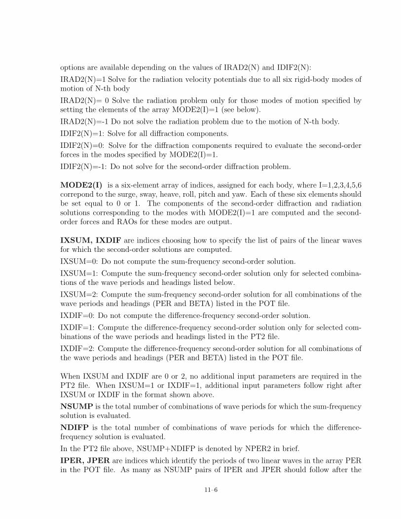
options are available depending on the values of IRAD2(N) and IDIF2(N):
IRAD2(N)=1 Solve for the radiation velocity potentials due to all six rigid-body modes ofmotion of N-th body
IRAD2(N)= 0 Solve the radiation problem only for those modes of motion specified bysetting the elements of the array MODE2(I)=1 (see below).
IRAD2(N)=-1 Do not solve the radiation problem due to the motion of N-th body.
IDIF2(N)=1: Solve for all diffraction components.
IDIF2(N)=0: Solve for the diffraction components required to evaluate the second-orderforces in the modes specified by MODE2(I)=1.
IDIF2(N)=-1: Do not solve for the second-order diffraction problem.
MODE2(I) is a six-element array of indices, assigned for each body, where I=1,2,3,4,5,6correpond to the surge, sway, heave, roll, pitch and yaw. Each of these six elements shouldbe set equal to 0 or 1. The components of the second-order diffraction and radiationsolutions corresponding to the modes with MODE2(I)=1 are computed and the second-order forces and RAOs for these modes are output.
IXSUM, IXDIF are indices choosing how to specify the list of pairs of the linear wavesfor which the second-order solutions are computed.
IXSUM=0: Do not compute the sum-frequency second-order solution.
IXSUM=1: Compute the sum-frequency second-order solution only for selected combina-tions of the wave periods and headings listed below.
IXSUM=2: Compute the sum-frequency second-order solution for all combinations of thewave periods and headings (PER and BETA) listed in the POT file.
IXDIF=0: Do not compute the difference-frequency second-order solution.
IXDIF=1: Compute the difference-frequency second-order solution only for selected com-binations of the wave periods and headings listed in the PT2 file.
IXDIF=2: Compute the difference-frequency second-order solution for all combinations ofthe wave periods and headings (PER and BETA) listed in the POT file.
When IXSUM and IXDIF are 0 or 2, no additional input parameters are required in thePT2 file. When IXSUM=1 or IXDIF=1, additional input parameters follow right afterIXSUM or IXDIF in the format shown above.
NSUMP is the total number of combinations of wave periods for which the sum-frequencysolution is evaluated.
NDIFP is the total number of combinations of wave periods for which the difference-frequency solution is evaluated.
In the PT2 file above, NSUMP+NDIFP is denoted by NPER2 in brief.
IPER, JPER are indices which identify the periods of two linear waves in the array PERin the POT file. As many as NSUMP pairs of IPER and JPER should follow after the
11–6

parameter NSUMP and NDIFP pairs of IPER and JPER after the parameter NDIFP.
NBETA2 is the total number of wave-heading pairs for each pair of period combination,IPER and JPER.
IBETA, JBETA are indices which identify the wave headings of two linear waves in thearray BETA in the POT file.
11.4 FREE SURFACE DATA FILE (FDF)
A FDF file must be prepared, unless IOPTN(I)=0 for I=11,12,... and 16.
The FDF file is used to input all requisite geometric data of the free surface exterior tothe bodies for the integration of the quadratic forcing over the entire free surface. Whenthe bodies have internal tanks with free surfaces, the geometric data of the internal freesurface may be included in the FDF file.
To perform the integration efficiently, different quadrature schemes are used depending onthe proximity of the domain to the bodies. The free surface is divided into three regionsusing two circles of radii, RINNER and Rpart where RINNER ≤ Rpart. Both circles arecentered at the origin of the global coordinates system. Three regions are denoted by theinner region, intermediate region and far-field. The inner region is inside a circle ofradius RINNER and exterior to the bodies. It also includes the free surface in internaltanks. The intermediate region is the annulus between RINNER and Rpart. The far-fieldis the entire free surface outside a circle of radius Rpart. Use of the intermediate region isoptional and, when it is omitted, Rpart=RINNER.
The geometry of the inner region can be represented in the similar manner as the bodygeometries in the GDF file. An important difference is the free surface geometry should bedefined in terms of global coordinates system. When ILOWHI=0, the region is repre-sented by an ensemble of qudrilateral panels specified by the horizontal coordinates of thevertices of the panels. When ILOWHI=1, the patches on the inner region can be describedby B-splines, explict formulae or using MultiSurf models. The vertical coordinates of thepanels or patches are assigned in the program and they are not required. They are set tozero for the exterior free surface and to the highest vertical coordinates of the panels orpatches on each tank wall.
The intermediate region can be represented with one or more sub-annuli of equal width.Specifically, the intermediate region is defined by three input parameters as described indetail later in this section. They are RINNER, NAL and DELR where NAL is the numberof sub-annuli and DELR is the width of sub-annuli. The outer circle of the intermediateregion is determined by Rpart=RINNER+NAL*DELR. The integration of the free surfaceforcing over each sub-annulus is performed using the Gauss Chebyshev quadrature in theazimuthal direction and the Gauss Legendre quadrature in the radial direction.
In the far-field, exterior to a circle of radius Rpart, integration is performed in a semi-analytic manner using asymptotic approximations of the integrand.
11–7

Except the parameters defining the inner region, other input parameters are common forall formats of the FDF file. These common parameters of the FDF file are described below.
headerRINNER(line 3)NAL DELR NCIRE NGSP(line 5)..
The parameters on lines 3, 5 and below are relevant to the definition of the inner region us-ing panels or patches. These parameters differ between different geometric representationsof the inner region and they are described in the subsequent sections.
header denotes a one-line ASCII header dimensioned CHARACTER 72. This line isavailable for the user to insert a brief description of the file.
RINNER is the dimensional radius of the inner circle with the center at the origin of theglobal coordinates system. RINNER is in the same unit as the length ULEN in the GDFfile.
NAL is the total number of sub-annuli of same thickness (or width) on the intermediateannular region. When NAL=0, the parameters DELR, NCIRE and NGSP are not required.
DELR is the dimensional width of a sub-annulus, in the same unit as ULEN.
NCIRE is the integer exponent of 2. The number of nodes is equal to 2NCIRE + 1 in theazimuthal integration based on Gauss-Chebyshev quadrature.
NGSP is the number of nodes used for the Gauss-Legendre quadrature in radial directionon each sub-annulus.
When NBODY=1, the geometric data in the inner region of the FDF file should containsone quadrant of, a half of, or the entire free surface depending on the symmetry of theproblem. When NBODY > 1, the entire inner region should be included in the FDF fileregardless of the symmetry of the individual bodies. Same interpretation is applied to theparameter NCIRE which assigns the number of nodes on a quarter of, a half of or thewhole circumference.
A guidance to estimate RINNER, NAL and DELR is provided in Section 11.8. To deter-mine appropriate values of NCIRE and NGSP, it is advised to increase these parametersuntil the computational results are consistent. To determine proper vaules for NCIRE andNGSP on a sub-annulus, the panels or patches in the inner region may be omitted. Thoughthe computational results are not physically correct because the free surface forcing in theinner region is ignored, they can be used to efficiently determine adequacy of NCIRE andNGSP parameters for the integration of the forcing in the intermediate region.
In the following sections, various formats of the FDF file are presented.
11–8

11.5 FDF FOR THE LOW-ORDER METHOD (ILOWHI=0)
Three options are available to describe the inner region for ILOWHI=0 as shown below.
11.5.1 INNER REGION REPRESENTED BY PANELS
In this option, the inner region of the free surface is represented by an ensemble of connectedfour-sided facets in a similar manner as the body surface is represented by panels. Threemajor differences to the GDF file are i) the vertical coordinates of the free surface areassigned in the program and they should not be included in the FDF file, ii) there isno preference in the vertex ordering and both clockwise and anti-clockwise direction isacceptable and iii) the format to specify the coordinates of the vertices is different.
The complete data in the FDF file are listed below.
headerRINNERNPF NTCLNAL DELR NCIRE NGSPVERX(1,1) VERX(2,1) VERX(3,1) VERX(4,1)VERY(1,1) VERY(2,1) VERY(3,1) VERY(4,1)...VERX(1,NPF) VERX(2,NPF) VERX(3,NPF) VERX(4,NPF)VERY(1,NPF) VERY(2,NPF) VERY(3,NPF) VERY(4,NPF)
The descriptions of the parameters on lines 1, 2 and 4 can be found in Section 11.4.
NPF is the total number of free surface panels in the inner region.
NTCL is the total number of line segments of equal length on the inner circle of radiusRINNER.
VERX(K,I), K=1,2,3,4 is the dimensional x coordinate of the K-th vertex of the I-thpanel, in the global coordinates system.
VERY(K,I), K=1,2,3,4 is the dimensional y coordinate of the K-th vertex of the I-thpanel, in the global coordinates system
When the internal tanks are present and the panels on the internal free surface are alsospecified in the global coordinates system.
11.5.2 AUTOMATIC DEFINITION OF INNER REGION
In this option, the inner region is defined automatically without specifying panels. Toinvoke this option, -1 should be specified for NPF. It is followed by a real parameterSCALE. The complete input data are as follow.
11–9

headerRINNER-1 SCALENAL DELR NCIRE NGSP
The descriptions of the parameters on lines 1, 2 and 4 can be found in Section 11.4.
NPF=-1 should be specified to activate automatic subdivision of the inner region intopanels.
SCALE is a real number used as a scaling factor of the size of the panels in the innerregion relative to the average length of the waterline panels on the body. For example, ifSCALE=1.5, the length scale of free surface panels will be 1.5 times the average length ofthe sides of the body panels which form the waterlines.
When there are multiple waterlines, the average length of waterline segments should besmaller than a half of the mimimum distance between two waterlines in order to usethis option. This requires sufficiently small waterline panels on the body, when the gapbetween the waterlines are small. In this case, a large value of SCALE may be used toavoid unecessarily small free surface panels on the inner region.
11.5.3 INNER RERION REPRESENTED BY MULTISURF MODELS
MultiSurf users may create a MultSurf model, MS2, containing the inner region of the freesurface, and discretize the inner region and inner circle with an appropriate distribution ofpanels and the line segments. The number of panels and line segments correspond to theparameters NPF and NTCL described in the previous section.
The panel vertices and the parameters NPF and NTCL may be exported to a FDF file, fromMutliSurf, in the format described in Section 11.5.1. Alternatively the name of MultiSurfmodel, a .ms2 file, can specified in the FDF file instead of the panel vertices. This formatwill be refered to as the short form FDF file. In order to use the shor form, it is requiredto install rg2wamit.dll and rgkernel.dll as explianed in Appendix C.
The short form FDF input file should be in the following format:
headerRINNER-2 NTCLNAL DELR NCIRE NGSP1 (NLINES)(path) filename.ms2
The descriptions of the parameters on lines 1, 2 and 4 can be found in Section 11.4.
NPF=-2 should be specified on the 3rd line as shown above.
NLINES on the 5th line is the number of subsequent lines on which the name of the .ms2file containing the inner region of the free surface and other relevant parameters of the
11–10
model.
filename.ms2 on the 6th line is the name of a MultiSurf model.
When a short form FDF file is used, the geometric data of the MultiSurf model is exportedto an auxilliary file fdf ms2.fdf, where fdf denotes the name of the short form FDF file.This file contains the panel vertices and all other input parameters in the FDF file in theformat shown Section 11.5.1.
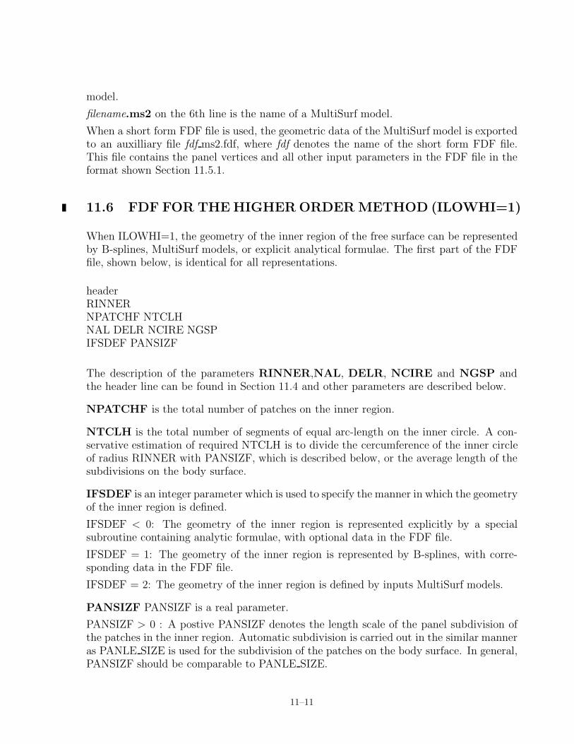
11.6 FDF FOR THE HIGHER ORDER METHOD (ILOWHI=1)
When ILOWHI=1, the geometry of the inner region of the free surface can be representedby B-splines, MultiSurf models, or explicit analytical formulae. The first part of the FDFfile, shown below, is identical for all representations.
headerRINNERNPATCHF NTCLHNAL DELR NCIRE NGSPIFSDEF PANSIZF
The description of the parameters RINNER,NAL, DELR, NCIRE and NGSP andthe header line can be found in Section 11.4 and other parameters are described below.
NPATCHF is the total number of patches on the inner region.
NTCLH is the total number of segments of equal arc-length on the inner circle. A con-servative estimation of required NTCLH is to divide the cercumference of the inner circleof radius RINNER with PANSIZF, which is described below, or the average length of thesubdivisions on the body surface.
IFSDEF is an integer parameter which is used to specify the manner in which the geometryof the inner region is defined.
IFSDEF < 0: The geometry of the inner region is represented explicitly by a specialsubroutine containing analytic formulae, with optional data in the FDF file.
IFSDEF = 1: The geometry of the inner region is represented by B-splines, with corre-sponding data in the FDF file.
IFSDEF = 2: The geometry of the inner region is defined by inputs MultiSurf models.
PANSIZF PANSIZF is a real parameter.
PANSIZF > 0 : A postive PANSIZF denotes the length scale of the panel subdivision ofthe patches in the inner region. Automatic subdivision is carried out in the similar manneras PANLE SIZE is used for the subdivision of the patches on the body surface. In general,PANSIZF should be comparable to PANLE SIZE.
11–11

PANSIZF < 0 : A negative PANSIZF denotes that the subdivsion of the patches in theinner region is made using the parameters specified in the fdf fdf.spl file. The fdf fdf.splfile is described in Section 11.7.
11.6.1 INNER REGION REPRESENTED BY B-SPLINES (IFSDEF=1)
Each patch of the inner region is represented by B-spline, in an analogous manner to therepresentation of the body surface (IGDEF=1). The panel subdivision (knot vector), theorder of the B-splines and the coefficients of the B-splines for x and y coordinates in termsof the global coordinates system are specified as follow.
headerRINNERNPATCHF NTCLHNAL DELR NCIRE NGSP1 PANSIZFNUF(1) NVF(1)KUF(1) KVF(1)VKNTUF(1,1) ... VKNTUF(NUA(1),1)VKNTVF(1,1) ... VKNTVF(NVA(1),1)XCOEF(1,1) XCOEF(2,1)XCOEF(1,2) XCOEF(2,2)···XCOEF(1,NB(1)) XCOEF(2,NB(1))···NUF(NPATCHF) NVF(NPATCHF)KUF(NPATCHF) KVF(NPATCHF)VKNTUF(1,NPATCHF) ... VKNTUF(NUA(NPATCHF),NPATCHF)VKNTVF(1,NPATCHF) ... VKNTVF(NVA(NPATCHF),NPATCHF)XCOEF(1,1) XCOEF(2,1)XCOEF(1,2) XCOEF(2,2)···XCOEF(1,NB(NPATCHF)) XCOEF(2,NB(NPATCHF))
The descriptions of the parameters RINNER,NAL, DELR, NCIRE and NGSP andthe header line are in Section 11.4. The description of PANSIZF can be found in Section11.6. Other parameters are described below.
11–12
IFSDEF=1 is assigned on line 5. This signifies the B-spline representation of the patchesin the inner region of the free surface.
NUF(I) and NVF(I) are the numbers of panel subdivisions in the u and v coordinates,respectively, on I-th patch.
KUF(I) and KVF(I) are the orders of B-splines in the u and v coordinates, respectively,on I-th patch.
VKNTUF(J,I) is the B-spline knot vector in u on patch I. J=1,2,...NUA(I)NUA(I)=NUF(I)+2*KUF(I)-1.
VKNTVF(J,I) is the B-spline knot vector in v on patch I. J=1,2,...NVA(I)NVA(I)=NVF(I)+2*KVF(I)-1.
XCOEF(1,K) and XCOEF(2,K) are the components of the vector coefficient similarto Xij in equation (6.6). These are defined in terms of the single array index K, whereK=1,2,...,NB(I). Here NB(I) is the total number of coefficients on patch I, given by therelation NB(I)=(NUF(I)+KUF(I)-1)×(NVF(I)+KVF(I)-1).
The coefficient corresponding to the vertical coordinate XCOEF(3,K) may be included inthe FDF file, if it is on the same line with XCOEF(1,K) and XCOEF(2,K) and followedby a line breaker. However, XCOEF(3,K) is not used in the program. Instead, the verticalcoordinates are set to 0 for the exterior free surface and to the highest Z-coordinates of thepatches in each tank.
11.6.2 INNER REGION REPRESENTED BY EXPLICIT FORMULAE (IFS-DEF < 0)
This option may be used when the geometry of the inner region can be defined by explicitformulae. The formulae required to define the inner region must be coded in FORTRAN,as subroutines in the file FDEXACT.F. Subroutines already provided in this file may beuseful to understand the appropriate procedures for developing new subroutines. Thisfile can be compiled separately as a .dll file, FDEXACT.DLL, and linked with WAMITat runtime, following the same procedure to modify GEOMXACT.DLL, as described inSection 6.9.
In general, these subroutines contain generic patterns or shapes of the inner region withoutspecific dimensions or other conditions (”parameters”). Parameters specific for each prob-lem under consideration may be written in the FDF files and input to the subroutine atruntime. For example, the inner region for vertical cylidrical columns may be representedby an annulus extending from the circular intersection of the column with the free surfaceto the outer circle of radius RINNER. The radii of the smaller and larger circles of annulusmay be specified in the FDF file as input parameters and the corresponding subroutine inFDEXACT.F may have READ statements to read these parameters.
The format of the FDF file is as follows:
headerRINNER
11–13

NPATCHF NTCLHNAL DELR NCIRE NGSPIFSDEF PANSIZFNLINESline 1line 2...line NLINES
The descriptions of the parameters RINNER,NAL, DELR, NCIRE and NGSP andthe header line are in Section 11.4. The description of IFSDEF and PANSIZF can befound in Section 11.6.
NLINES is the number of lines containing parameters. The parameters should be specifiedon the following NLINES lines in the same format in READ statements in the subrountine.
Continuing with above example of an annular inner region, if two radii of the annulus aredenoted by RI and RO, with RI < RO, the following formula represents the first quadrantof the inner region.
T =π
4(u + 1) and R =
(RO − RI)
2(v + 1) + RI, for − 1 ≤ u, v ≤ 1
X = R cosT and Y = R sin T
As shown in this example, the domain of parametric coordinates u and v must be (-1.,1),in the expressions of the explicit formalae for each patch.
11.6.3 INNER REGION REPRESENTED BY MULTISURF (IFSDEF = 2)
The inner region may be represented using MS2 geometry database files from MultiSurf inthe similar manner as the body geometries are represented. In order to use this option, itis required to install rg2wamit.dll and rgkernel.dll. The MS2 files should include the entireinner region described in the global coordinates system. The vertical coordiantes of thefree surface specified in the MS2 files are ignored in WAMIT and they are automaticallyset to zero for the exterior free surface or to the vertical coordiantes of the free surfaces inthe internal tanks.
The FDF input file takes the following format in the simplest form.
headerRINNERNPATCHF NTCLHNAL DELR NCIRE NGSP2 PANSIZF3
11–14

(path) fdf.ms2*0 0 0
The first four lines and the real parameter PANSIZF on line 5 are explained in Sections11.4 and 11.6.
IFSDEF=2 is assigned on line 5, signifying the use of the MS2 file. Line 6 containsan integer specifying the number of subsequent lines to be read from the .fdf file. Line 7contains the name of the .ms2 file. The asterisk (*) on line 7 is a default specifier to indicatethat all visible surfaces in the .ms2 file are to be included; alternatively if only a subsetof these surfaces are submerged these may be designated by following the instructionsin Appendix C. Line 8 includes three integer parameters with default values zero, whichmay be used to control the accuracy of the geometry evaluation in RGKernel, and also tomodify the convention regarding the direction of the unit normal. Further information iscontained in Appendix C.
NPATCHF can be specified as 0. Use of this option is recommended, to avoid errorsin counting surfaces or patches. In the case the number of patches is evaluated from theMultiSurf model, and the user does not need to input NPATCHF separately. If NPATCHF> 0 is input by the user, the number of MultiSurf patches used in the solution will be limitedto NPATCHF.
11.6.4 AUTOMATIC DEFINITION OF INNER REGION
In this option, the inner region is defined automatically without specifying the patches bythe users.
To invoke this option, a negative integer should be specified for NPATCHF and it shouldbe followed by a real parameter PANSIZF as described below. The complete input dataare as follow.
headerRINNER-1 PANSIZFNAL DELR NCIRE NGSP
The descriptions of the parameters RINNER,NAL, DELR, NCIRE and NGSP andthe header line are in Section 11.4.
NPATCHF=-1 should be specified on the 3rd line as shown above.
PANSIZF PANSIZF is a real parameter.
PANSIZF > 0 : A postive PANSIZF denotes the length scale of the subdivision of thepatches in the inner region. It is used for automatic subdivision in the similar manner asPANLE SIZE is used for the body surface.
PANSIZF < 0 : A negative PANSIZF denotes that the subdivsion of the patches in the
11–15

inner region is made using the parameters specified in the fdf fdf.spl file. This file must beprepared by the user. The fdf fdf.spl file is described in a section below.
When there are multiple waterlines, the current option may not be used in the followingsituation. When the smallest rectangles drawn around each waterline, with the sidesparellel to two horizontal axes of the global coordinates system, if any of these rectanglesare overlapped, the current option can not be used. In this case, users may rotate thepositions of the bodies, around the origin of the global coordinates system, to avoid theoverlapping of the rectangles. If that is not possible, other options for the FDF file shouldbe used.
11.7 OPTIONAL SPLINE CONTROL FILE (ILOWHI=1)
The optional FDF.SPL file may be used to specify the panel subdivision on each patchin the inner region of the free surface in the similar manner as SPL is used for the bodysurface. In general, the size of the panels on the inner region of the free surface should becomparable to the panels on the body surface. If the FDF.SPL file is used, PANSIZF<0must be specified in the FDF file and FDF.SPL file must have the same filename as theFDF file, with the extension ‘ fdf.spl’.
The complete data in the FDF.SPL file are as follow.
headerNU(1) NV(1)NU(2) NV(2)..NU(NPATCHF) NV(NPATCHF)
NU and NV are the numbers of subdivision along the u and v coordinates of each patchin the inner region.
11.8 SPECIAL TOPICS ON FDF
11.8.1 PARTITION CIRCLE AND INNER CIRCLE
As noted in Section 11.4, the radius of the partition circle, Rpart=RINNER+NAL×DELR,should be sufficiently large such that the asymptotic expansion of the potentials is validoutside of the circle. An appropriate estimation of the radius of the partition circle, Rpart,is O(h) (h=water depth) for shallow water and O(λ) (λ= longest wavelength involved)for deep water (h >> λ). The actual constant of proportionality Rpart/λ may have to besubstantially larger than one to achieve accuracy in deep water (see Reference [9] and [12]).
As the Gauss quadrature over the intermediate region is more efficient than the piecewiseintegration in the inner region, the smaller RINNER is, the integration of the forcing is
11–16

more efficient in general. However, if the inner circle of radius RINNER is too close to thebody, Gauss quadrature may not be efficient due to the influence of the Rankine sources.If the farthest radial distance of the body surface from the origin of the global coordinatessystem is denoted as Rbody, the following table shows the required number of nodes in theazimuthal integration of the influence of Rankine source as RINNER varies. In the table,NCIR=2NCIRE + 1 is the number of nodes of the Gauss-Chebyshev quadrature between[0, 2π]. A recommended procedure to determine RINNER is i) first to select the parameterNCIRE which would be dependent on the wavelengths of the linear and second-order wavesand ii) find RINNER from the table.
Rbody/RINNER NCIRE NCIR
0.1 3 90.4 4 270.5 5 330.8 6 650.9 7 1290.95 9 257
When field quantities are evaluated on the free surface, such as the second-order waveelevation, similar consideration applys. The maximum radial distance to the field pointsshould be sufficiently smaller than RINNER. Above table can be used to estimate RINNERafter replacing Rbody with the maximum radial distance to the field points.
Unlike the piecewise integration in the inner region, inadequate values of NCIRE and NGSPfor the integration over the intermediate region may produce the computational results withgross error. It is recommended to examine the dependence of the computational results tothese parameters.
11.8.2 RESTRICTION ON VERY LONG WAVES
When kiR, kjR or k±2 R is less than BOUND in the DATA statement of subroutine FARFS.F
and RHSFFS.F, the program will continue to run but neglect the integration over the outerregion in the total second-order exciting forces. Here R is the partition radius and ki, kj
and k±2 are wavenumbers associated with the frequencies ωi, ωj and ωi ± ωj . This case
may be encountered when a very long wavelength is involved in the difference-frequencysolution. If this occurs a warning message will appear in the log file. To avoid this conditionthe user may increase the partition radius.
In V6.4S, BOUND is set to 10−3. Depending on the range of the double-precision floating-point decimal exponent of the computing system, the source code users can modify thisvalue as follows. On the system where the exponent is in the range ± 64 × n, the recom-mended value of BOUND is 10−n.
11–17

11.8.3 APPROXIMATION WITHOUT FREE SURFACE FORCING
An approximated second-order solution may be obtained excluding the contribution of thefree surface forcing to the second-order scattering potential. As significant computationaleffort is required to account to the free surface forcing, the approximated solution canbe evaluated efficiently. However, since the quality of the approximation depends on theproblem, it must be used with discretion. In particular, this option is not recommendedfor the sum-frequency solution.
By specifying a negative number for the parameter RINNER in the FDF file, the effect ofthe free surfacing is omitted in the second-order solution. An example of the FDF file isshown below.
header-1where RINNER = -1 is specified.
11.8.4 AUXILIARY OUTPUT FILES
When IPLATDAT > 0 in the .cfg file, fdf pan.dat and fdf pat.dat are output for the innerregion of the free surface in the same way gdf pan.dat and gdf pat.dat are for the bodygeometry. The latter files are explained in Section 10.6. These files contain the vertexcoordinates of the free surface panels or subdivisions in a format suitable for input toplotting programs such as Tecplot. This facilitates the use of perspective plots to illustrateand check the FDF inputs or automatic representation of the inner region.
When ILOWGDF > 0 and ILOWHI=1 in the .cfg file, fdf low.fdf is output in the similarway gdf low.gdf is output. The data in fdf low.fdf has the same definitions of the freesurface geometry in fdf.fdf but in the FDF format for ILOWHI=0.
11.9 FNAMES.WAM
When FNAMES.WAM is used to list the input files, the PT2 and FDF file names can bespecified in addition to input files for V6.4 as shown in an example below.
FNAMES.WAM:test.cfgtest.gdftest.pottest.frctest.pt2test.fdf
If all second-order output options are suppressed, PT2 and FDF can be omitted. If allsecond-order output options are suppressed except )ption 10, FDF can be omitted.
11–18

11.10 DEFINITIONS OF OUTPUT
The second-order forces and other quantities evaluated by WAMIT V6.4S are output ina standard nondimensional form as described below. All second-order output satisfiessymmetry relations F+
ij = F+ji and F−
ij = F−ji
∗. Here + and − denote sum and difference
frequency quantities, respectively, ij or ji ordered pair of frequency indices and ∗ the com-plex conjugate. In the difference frequency output F−
ij , ωi ≥ ωj is assumed. When ωi < ωj
the indices are interchanged within the program and F−ji is output (F−
ij can be obtainedfrom the symmetry relation).
1. The second-order wave forces and moments at sum- and difference-frequencies aredefined as
F̄+ =F+
ρgLAiAjand F̄− =
F−
ρgLAiA∗j
M̄+ =M+
ρgL2AiAjand M̄− =
M−
ρgL2AiA∗j
where L=ULEN is the characteristic body length, and Ai,j, g and ρ represent the complexfirst-order incident-wave amplitudes, gravitational acceleration and fluid density, respec-tively.
2 The second-order hydrodynamic pressure at sum- and difference-frequencies is defined as
p̄+ =p+
ρgAiAj/Land p̄− =
p−
ρgAiA∗j/L
3. The second-order wave elevation at sum- and difference-frequencies is defined as
η̄+ =η+
AiAj/Land η̄− =
η−
AiA∗j/L
4. The second-order response amplitude operator at sum- and difference-frequencies isdefined as
ξ̄+k =
ξ+k
AiAj/Lnand ξ̄−k =
ξ−kAiA∗
j/Ln
where n = 1 for the translational modes k = 1, 2, 3 and n = 2 for the rotational modesk = 4, 5, 6
11.11 NUMERIC OUTPUT FILES
For each of the seven options of the second-order hydrodynamic output, separate outputfiles of numeric data are generated as listed in Section 11.2. The data in these numeric
11–19

output files are listed in the following format:
OPTN.10s, OPTN.qcs, OPTN.11s and OPTN.12s:PER(i) PER(j) BETA(i) BETA(j) I MOD(F̄+
ij ) PHS(F̄+ij ) Re(F̄+
ij ) Im(F̄+ij )
OPTN.10d, OPTN.qcd, OPTN.11d and OPTN.12d:PER(i) PER(j) BETA(i) BETA(j) I MOD(F̄−
ij ) PHS(F̄−ij ) Re(F̄−
ij ) Im(F̄−ij )
OPTN.13S:PER(i) PER(j) BETA(i) BETA(j) M K MOD(p̄+) PHS(p̄+) Re(p̄+) Im(p̄+)
OPTN.13D:PER(i) PER(j) BETA(i) BETA(j) M K MOD(p̄−) PHS(p̄−) Re(p̄−) Im(p̄−)
OPTN.14S:PER(i) PER(j) BETA(i) BETA(j) L MOD(p̄+) PHS(p̄+) Re(p̄+) Im(p̄+)
OPTN.14D:PER(i) PER(j) BETA(i) BETA(j) L MOD(p̄−) PHS(p̄−) Re(p̄−) Im(p̄−)
OPTN.15S:PER(i) PER(j) BETA(i) BETA(j) N MOD(η̄+) PHS(η̄+) Re(η̄+) Im(η̄+)
OPTN.15D:PER(i) PER(j) BETA(i) BETA(j) M MOD(η̄−) PHS(η̄−) Re(η̄−) Im(η̄−)
OPTN.16S:PER(i) PER(j) BETA(i) BETA(j) I MOD(ξ̄+) PHS(ξ̄+) Re(ξ̄+) Im(ξ̄+)
OPTN.16D:PER(i) PER(j) BETA(i) BETA(j) I MOD(ξ̄−) PHS(ξ̄−) Re(ξ̄−) Im(ξ̄−)
Here I is the mode index, M is the index of a quadrant or half when the body has two orone planes of symmetry, respectively, K is the index of the panels on the body and L isthe index of the field points.
Only the second-order hydrodynamic pressure is output in .13s and .13d. The second-orderquadratic hydrostatic pressure, P̄±
sq , normalized in the same manner as the hydrodynamicpressure, can be calculated from the following expression.
11–20

P̄±sq =
1
4[(ξ̄4iξ̄
±6j
+ ξ̄±4jξ̄6i)x + (ξ̄5i ξ̄
±6j
+ ξ̄±5jξ̄6i)y − (ξ̄4i ξ̄
±4j
+ ξ̄6i ξ̄±6j
)z]
where ξ̄ is the normalized linear RAO and ξ̄− is the complex conjugate of ξ̄ = ξ̄+. Thesubscripts i and j denote the frequency indices and x, y and z are the coordinates of a pointon the body surface normalized by the parameter ULEN in the GDF file.
The hydrostatic pressure due to the second-order RAO can be calculated from the followingexpression where ξ̄± is the normalized second-order RAO.
P̄±sp = −(ξ̄±3 + ξ̄±4 × y − ξ̄±5 × x)
11.12 INSTALLATION AND SETUP
The WAMIT software includes the main executable program wamit.exe, the DLL fileslisted below, a complete set of input files for the standard test runs TESTn (n=01,02, ...),and the formatted output files TESTn.OUT for these test runs. The PC-executable VersionV6.4S-PC includes additional dynamic link library files (DLL) which must be installed inthe same directory (i.e. ‘folder’) as the executable file wamit.exe, or in a different folderwhich is included in the system path. If these DLL files are missing the program will notrun, regardless of the inputs and options specified. The required DLL files include specialWAMIT DLL files and also special Intel or Microsoft DLL files. The five required WAMITDLL files are
geomxact.dllnewmodes.dllfdexact.dllrg2wamit.dllrg2wamit2.dll
The extended Version including the capability to input MultiSurf models requires one addi-tional DLL file, rgkernel.dll, and two extended versions of rg2wamit.dll and rg2wamit2.dll.Version 6.4S-PC is compiled using Intel Visual Fortran (IVF), Version 12.1. The followingDLL files are required to run executable code compiled with IVF:
libifcoremd.dlllibmmd.dlllibiomp5md.dllmsvcr100.dllsvml dispmd.dll
These DLL files are distributed by Intel and may be redistributed to all users. Copies ofthese files are included with each distribution of WAMIT. Users may encounter a problemon some older PC systems, indicated by the runtime error message ‘The system cannotexecute the specified program’. This problem can be overcome by downloading and in-stalling the Microsoft Visual C++ 2005 Redistributable Package, which is available fromMicrosoft.
11–21

Before installing the software a new main directory (folder) should be made. The recom-mended name is c:\wamitv6, but the user may prefer to use a different drive or directoryname, with a maximum length of 40 characters for the string. The software must beunzipped using a local utility, and all unzipped files should be saved in the directoryc:nwamitv7 and in subdirectories corresponding to those in the zip file. If a different driveor directory name is used, this must be specified as USERID PATH in the configurationfile, as explained in Section 3.7. The text file readme.txt includes an outline of the di-rectory tree and files contained in the zip file. If any difficulties are encountered duringinstallation and testing the user should confirm that the subdirectories and files correspondto the description in readme.txt.
11–22