Embed Size (px)
Citation preview
Applications Cookbook Provolt™ Room Controller (PRC)
FOR REFERENCE ONLY
Version 5.0

TABLE OF CONTENTS
PAGE DESCRIPTION
1 PRC Small Office Single Zone
2 PRC Small Office Dual Zone
3 PRC Classroom
4 Stairwell Landing PRC, Dual Zone
5 Stairwell Landing PRC, Single Zone
6 PRC Common Area
7 PRC: Demand Response Terminations
8 UL924 Bypass, 0-10V “4-Wire” Provolt Dimmed Load
9 UL924 Bypass, Provolt, Auto ON/OFF, Manual ON/OFF
10 UL924 Bypass, Daylight Harvesting, Provolt Dimming, 2 Zones
11 UL924 Bypass, Daylight Harvesting, Provolt Dimming, 3 Zones

PRC COOKBOOK NOTES1. Refer to installation instructions for device-specific terminations2. Line feed 120/230/277VAC, 60Hz3. Ground not shown. Ground devices per applicable national and
local codes and best practices.4. For emergency power situations, illustrations assume transfer
switch by others upstream of shown devices5. Line voltage load not to exceed contact rating per device
specifications 6. Power packs receiving separate feeds for switched loads and self
power must have both feeds on the same phase7. All low-voltage loads not to exceed contact rating per device
specifications8. Maximum run length for analog wiring is 1,000’ @ #18 AWG9. Sensors wired in parallel will cause line voltage relay closure when
occupancy is detected by any unit10. Devices in series requiring contact closure from a single device,
(clock input, demand response, emergency, etc.) must follow these wiring conventions: first device in sequence provides the +V to the triggering relay; signal from closure attached to all devices in sequence input; com from first device in sequence attached to com on all devices in sequence
11. Applications requiring multiple power packs/power supplies at the same VDC: +V must never be tie together to all power packs/power supplies; com/DCC must be tied together to all power packs/power supplies and all powered devices.
12. Ultrasonic ceiling mount sensors should be located a minimum of six (6) feet from HVAC supply/return vents
13. Trough-mounted, pendant mounted and pendant-mounted indirect lighting sources affect the operation of locally mounted sensors. Contractor is responsible for adjusting sensor locations to allow for proper operation.
14. Contractor is responsible for proper sensitivity and time delay settings for non-adaptive products, following the manufacturer’s recommended placement, and field verification of circuits with respect to power pack placement
15. Contractor is responsible for coordinating the operational options of sensors and power packs with the specific work requirements: - Work relevant energy code requirements affect circuits to be controlled and their control characteristics - One power pack is required for each controlled circuit - Refer to power pack data sheet for output and installation guide for maximum number of sensors connected to a power pack - If multiple circuits are to be controlled by a sensor, auxiliary relays may be used in conjunction with a power pack
16. Ceiling sensors mounted over doorways should be placed one (1) foot inside the threshold
DRAWING SYMBOLS
17. Up to 100 Mark VII style ballasts may be controlled per daylighting zone by IRC 18. All relays shown in de-energized state19. Individually cap off unused leads 20. One-line parenthesis use: (x) - Function (#) - Terminal21. Plug load control—commercial receptacle P/Ns: Standard duplex: - Split control (1 outlet) CR015-1PX, CR020-1PX - Full control (2 outlets) CR015-2PX, CR020-2PX Decora: - Split control (1 outlet) 16252-1PX, 16352-1PX - Full control (2 outlets) 16252-2PX, 16352-2PX22. Control receptacle: - Quantity per application codes - Termination shown split receptacle. Termination per application codes. - Receptacle markings per applicable energy codes
No connection
Connection
Devices wired in parallel
DRAWING ABBREVIATIONSLC LumaCanLV Low voltageHV High voltage switch (maintained)LVM Low voltage switch (momentary)- equal to Leviton 1081(toggle) or Leviton 56081 (Decora) LVT Low voltage switch (maintained)-equal to Leviton 12021-2 (toggle) or Leviton 56021-2 (Decora)LV2 IRC low voltage switchUON Unless otherwise notedBLK BlackWHT WhiteBLU BlueYEL YellowORG OrangeVIO VioletBRN Brown
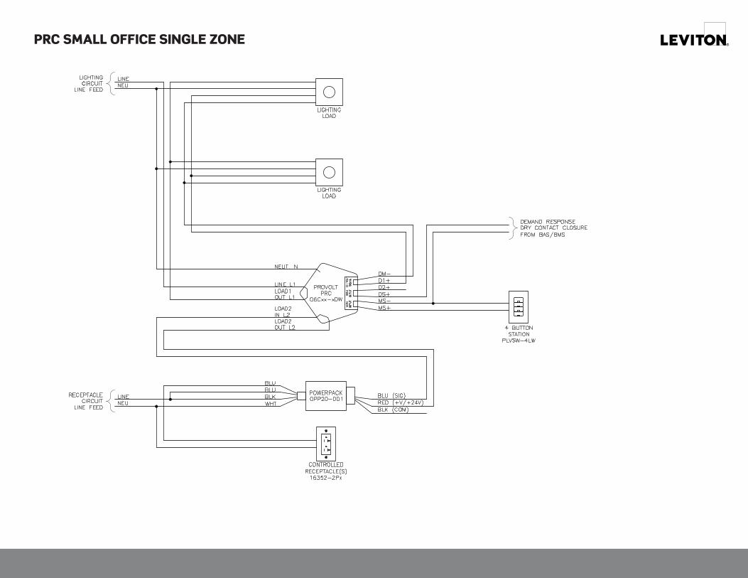
PRC SMALL OFFICE SINGLE ZONE

PRC SMALL OFFICE DUAL ZONE

PRC CLASSROOM

STAIRWELL LANDING PRC, DUAL ZONE

STAIRWELL LANDING PRC, SINGLE ZONE

PRC COMMON AREA

PRC: DEMAND RESPONSE TERMINATIONS

UL924 BYPASS, 0-10V “4-WIRE” PROVOLT DIMMED LOAD

UL924 BYPASS, PROVOLT, AUTO ON/OFF, MANUAL ON/OFF

UL924 BYPASS, DAYLIGHT HARVESTING, PROVOLT DIMMING, 2 ZONES

UL924 BYPASS, DAYLIGHT HARVESTING, PROVOLT DIMMING, 3 ZONES

G-9772F/F17-tbREV JUN 2017
Leviton Manufacturing Co., Inc. Global Headquarters201 North Service Road, Melville, NY 11747-3138 tel 800-323-8920 fax 800-832-9538 tech line (8:30AM-7:00PM ET Mon-Fri) 800-824-3005
Leviton Manufacturing Co., Inc. Energy Management, Controls and Automation20497 SW Teton Avenue, Tualatin, OR 97062 tel 800-736-6682 fax 503-404-5594 tech line (6:00AM-4:00PM PT Mon-Fri) 800-959-6004
Visit our Website at: www.leviton.com/provolt©2017 Leviton Manufacturing Co., Inc. All rights reserved. Subject to change without notice.