Embed Size (px)
Citation preview
DWL-AG700AP Install Guide
Version 1.0
ANT24-0700
High-Gain Indoor Antenna
2 D-Link Systems, Inc.
ANT24-0700 Install GuideSystem Requirements
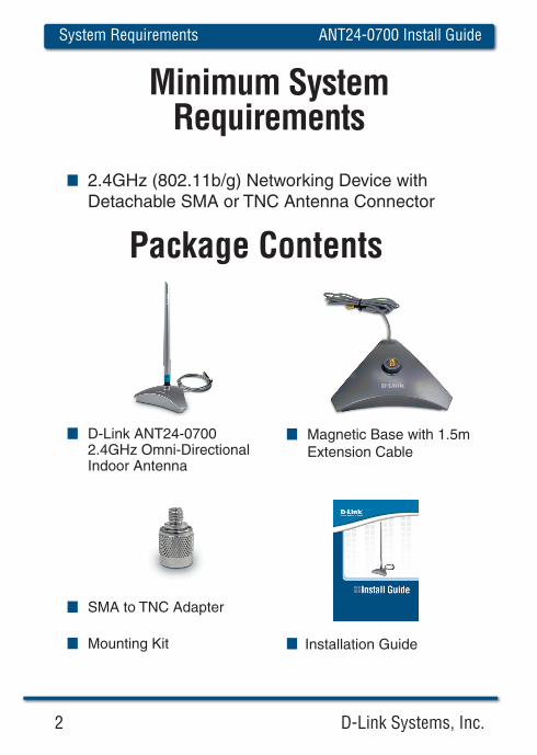
Package Contents
D-Link ANT24-07002.4GHz Omni-DirectionalIndoor Antenna
Mounting Kit
Magnetic Base with 1.5m Extension Cable
SMA to TNC Adapter
Installation Guide
2.4GHz (802.11b/g) Networking Device with Detachable SMA or TNC Antenna Connector
Minimum System Requirements
D-Link Systems, Inc. 3
ANT24-0700 Install Guide Hardware Overview
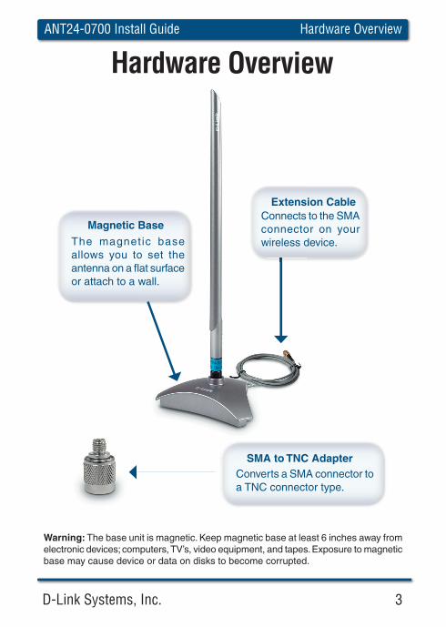
Hardware Overview
The magnetic base allows you to set the antenna on a fl at surface or attach to a wall.
Magnetic BaseConnects to the SMA connector on your wireless device.
Extension Cable
Converts a SMA connector to a TNC connector type.
SMA to TNC Adapter
Warning: The base unit is magnetic. Keep magnetic base at least 6 inches away from electronic devices; computers, TV’s, video equipment, and tapes. Exposure to magnetic base may cause device or data on disks to become corrupted.
4 D-Link Systems, Inc.
ANT24-0700 Install GuideAntenna Installation
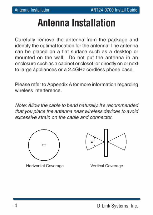
Carefully remove the antenna from the package and identify the optimal location for the antenna. The antenna can be placed on a fl at surface such as a desktop or mounted on the wall. Do not put the antenna in an enclosure such as a cabinet or closet, or directly on or next to large appliances or a 2.4GHz cordless phone base.
Please refer to Appendix A for more information regarding wireless interference.
Note: Allow the cable to bend naturally. It’s recommended that you place the antenna near wireless devices to avoid excessive strain on the cable and connector.
Horizontal Coverage Vertical Coverage
Antenna Installation
D-Link Systems, Inc. 5
ANT24-0700 Install Guide Antenna Installation
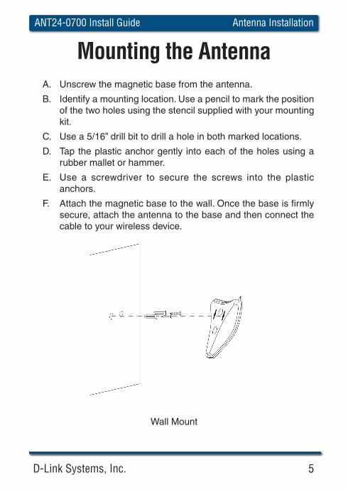
A. Unscrew the magnetic base from the antenna.
B. Identify a mounting location. Use a pencil to mark the position of the two holes using the stencil supplied with your mounting kit.
C. Use a 5/16” drill bit to drill a hole in both marked locations.
D. Tap the plastic anchor gently into each of the holes using a rubber mallet or hammer.
E. Use a screwdriver to secure the screws into the plastic anchors.
F. Attach the magnetic base to the wall. Once the base is fi rmly secure, attach the antenna to the base and then connect the cable to your wireless device.
Wall Mount
Mounting the Antenna
6 D-Link Systems, Inc.
ANT24-0700 Install GuideAntenna Installation
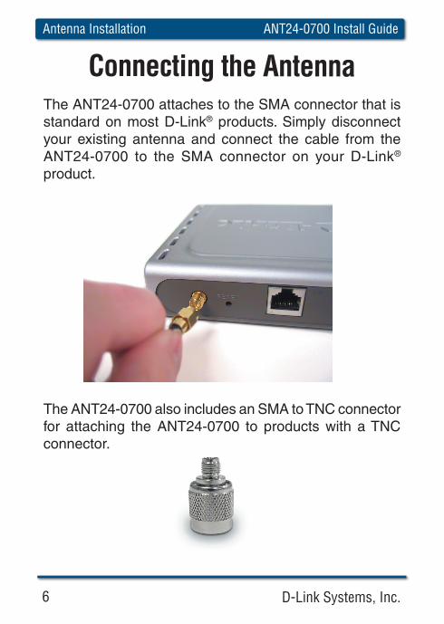
Connecting the AntennaThe ANT24-0700 attaches to the SMA connector that is standard on most D-Link® products. Simply disconnect your existing antenna and connect the cable from the ANT24-0700 to the SMA connector on your D-Link® product.
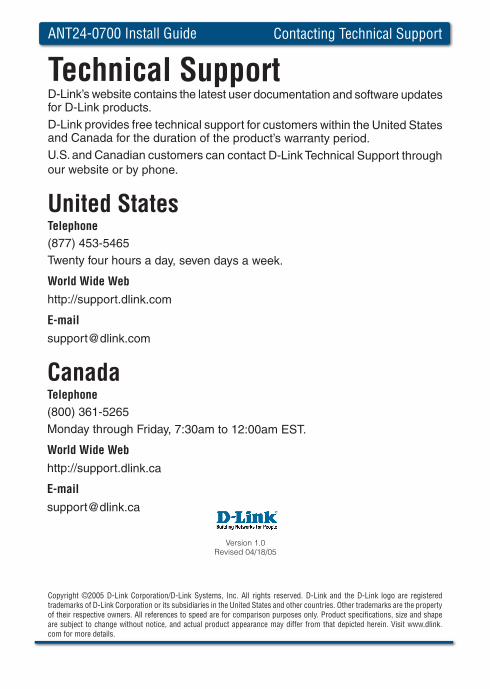
The ANT24-0700 also includes an SMA to TNC connector for attaching the ANT24-0700 to products with a TNC connector.
D-Link Systems, Inc. 7
ANT24-0700 Install Guide Appendix A
Appendix AWireless Interference
D-Link wireless products let you access your network from anywhere you want. However, keep in mind, that range is limited by the number of walls, ceilings, or other objects that the wireless signals must pass through. Typical ranges vary depending on the types of materials and background RF noise in your home or business. The key to maximizing range is to follow these basic principles:
1. Keep the number of walls and ceilings to a minimum. Each wall or ceiling can rob your D-Link wireless product of 3-90 ft. of range. Position your access points, wireless routers, and computers so that the number of walls or ceilings is minimized.
2. Be aware of the direct line between access points, routers, and computers. A wall that is 1.5 feet thick, at a 45 degree angle, appears to be almost 3 feet thick. At a 2-degree angle it looks over 42 feet thick! Try to make sure that the access point and wireless adapters are positioned so that the signal will travel straight through a wall or ceiling for better reception.
3. Building Materials make a difference. A solid metal door or aluminum studs may have a negative effect on range. Try to position access points, wireless routers, and computers so that the signal passes through drywall or open doorways. Materials and objects such as glass, steel, metal, walls with insulation, water (fi sh tanks), mirrors, fi le cabinets, brick, and concrete will degrade your wireless signal.
4. Keep your product away (at least 3-6 feet) from electrical devices that generate RF noise, like microwave ovens, UPS units, monitors, electric motors, etc.
5. If you are using 2.4GHz cordless phones or X-10 (wireless products such as ceiling fans, lights, and home security systems), your wireless connection may degrade dramatically or drop completely. Make sure your 2.4GHz phone base is as far away from your wireless devices as possible. The base transmits the signal even if the phone in not in use.
ANT24-0700 Install Guide Contacting Technical Support
Technical SupportD-Link’s website contains the latest user documentation and software updates for D-Link products.D-Link provides free technical support for customers within the United States and Canada for the duration of the product’s warranty period.U.S. and Canadian customers can contact D-Link Technical Support through our website or by phone.
United StatesTelephone (877) 453-5465Twenty four hours a day, seven days a week.
World Wide Webhttp://support.dlink.com
CanadaTelephone (800) 361-5265Monday through Friday, 7:30am to 12:00am EST.
World Wide Webhttp://support.dlink.ca
Version 1.0Revised 04/18/05
Copyright ©2005 D-Link Corporation/D-Link Systems, Inc. All rights reserved. D-Link and the D-Link logo are registered trademarks of D-Link Corporation or its subsidiaries in the United States and other countries. Other trademarks are the property of their respective owners. All references to speed are for comparison purposes only. Product specifi cations, size and shape are subject to change without notice, and actual product appearance may differ from that depicted herein. Visit www.dlink.com for more details.


![Design of Ionofree Micro Strip Quad Helix Antenna for ... · antenna, bifilar helices antenna, microstrip antenna, quadrafilar helix antenna. ... Helical antenna [1],[2] is broadband](https://img.pdfslide.us/doc/110x75/5b9506e809d3f2ea5c8b5a04/design-of-ionofree-micro-strip-quad-helix-antenna-for-antenna-bifilar-helices.jpg)