Embed Size (px)
Citation preview
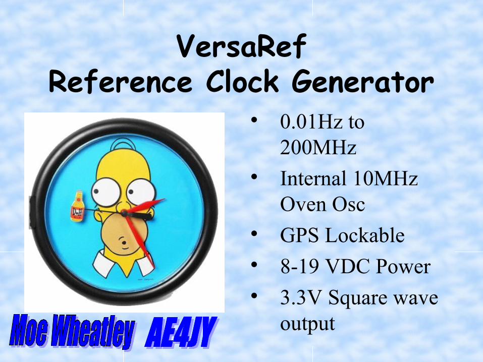
VersaRefReference Clock Generator
0.01Hz to 200MHz
Internal 10MHz Oven Osc
GPS Lockable 8-19 VDC Power 3.3V Square wave
output
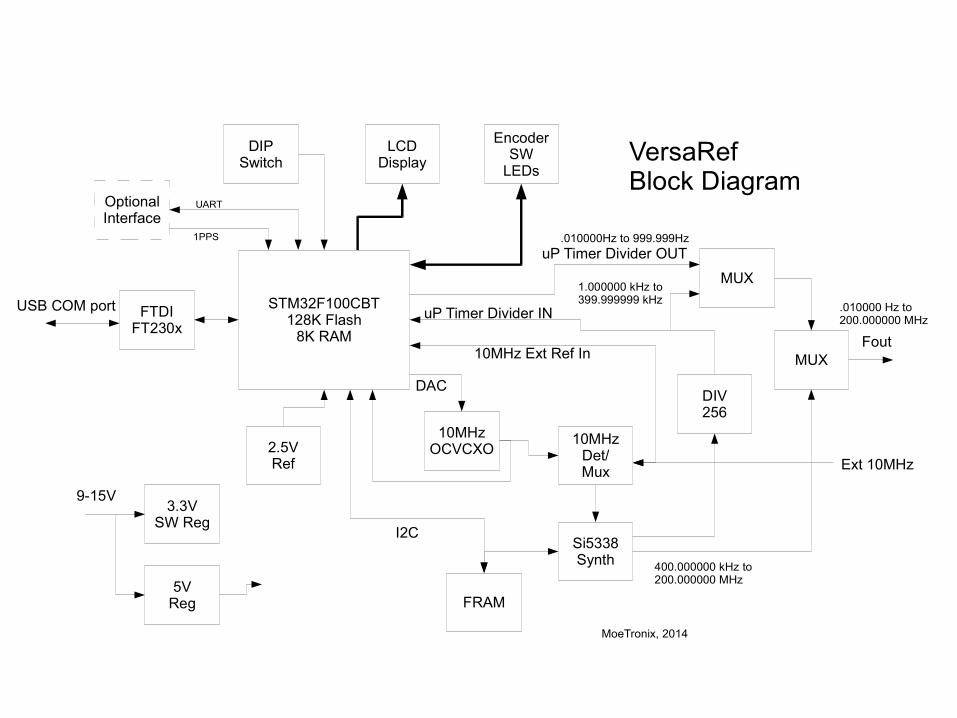
DIPSwitch
3.3VSW Reg
5VReg
10MHzOCVCXO
STM32F100CBT128K Flash
8K RAM
FTDIFT230x
Si5338Synth
FRAM
MUX
LCDDisplay
EncoderSW
LEDs
9-15V
USB COM port
2.5VRef
10MHzDet/Mux
uP Timer Divider OUT
Ext 10MHz
I2C
uP Timer Divider IN
Fout
VersaRefBlock Diagram
MoeTronix, 2014
DIV256
MUX
DAC
10MHz Ext Ref In
400.000000 kHz to 200.000000 MHz
1.000000 kHz to 399.999999 kHz
.010000Hz to 999.999Hz
.010000 Hz to 200.000000 MHz
OptionalInterface
UART
1PPS
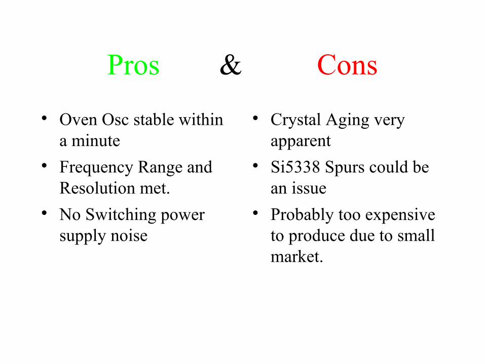
Pros & Cons
Oven Osc stable within a minute
Frequency Range and Resolution met.
No Switching power supply noise
Crystal Aging very apparent
Si5338 Spurs could be an issue
Probably too expensive to produce due to small market.
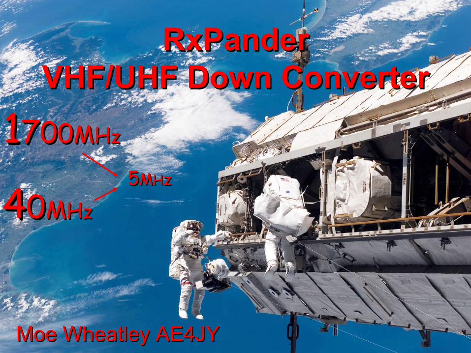
Moe Wheatley AE4JYMoe Wheatley AE4JY
RxPanderRxPanderVHF/UHF Down ConverterVHF/UHF Down Converter
55MMHHzz
11770000MMHHzz
4400MMHHzz
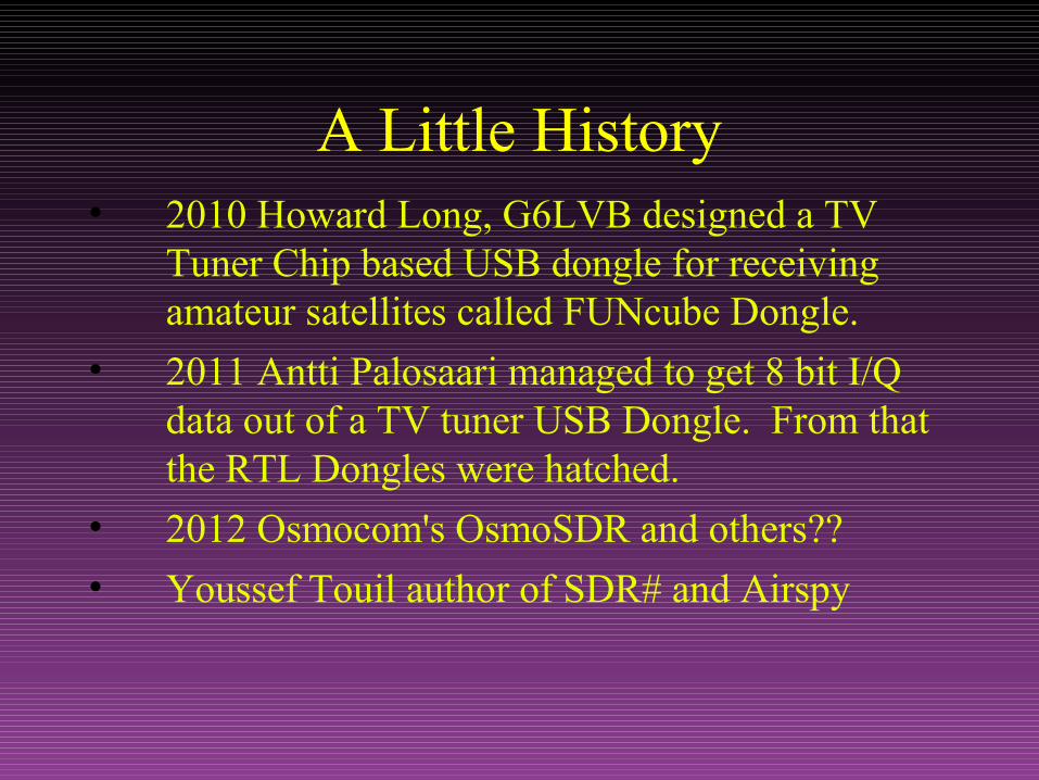
A Little History• 2010 Howard Long, G6LVB designed a TV
Tuner Chip based USB dongle for receiving amateur satellites called FUNcube Dongle.
• 2011 Antti Palosaari managed to get 8 bit I/Q data out of a TV tuner USB Dongle. From that the RTL Dongles were hatched.
• 2012 Osmocom's OsmoSDR and others??
• Youssef Touil author of SDR# and Airspy
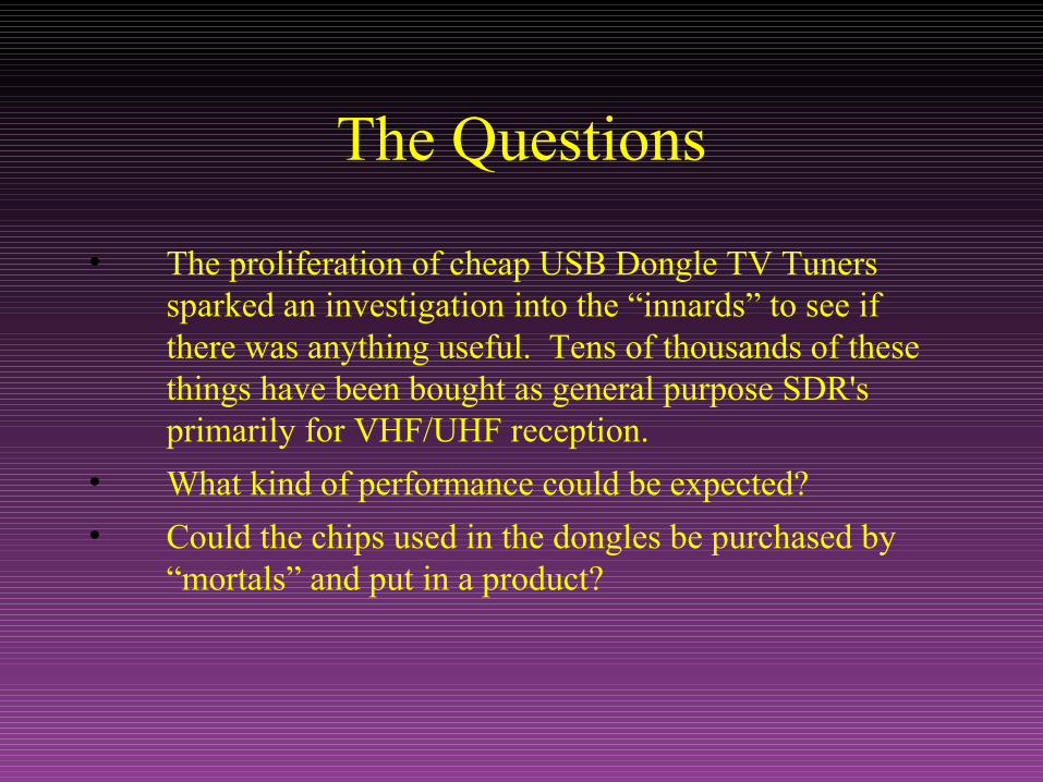
The Questions
• The proliferation of cheap USB Dongle TV Tuners sparked an investigation into the “innards” to see if there was anything useful. Tens of thousands of these things have been bought as general purpose SDR's primarily for VHF/UHF reception.
• What kind of performance could be expected?
• Could the chips used in the dongles be purchased by “mortals” and put in a product?
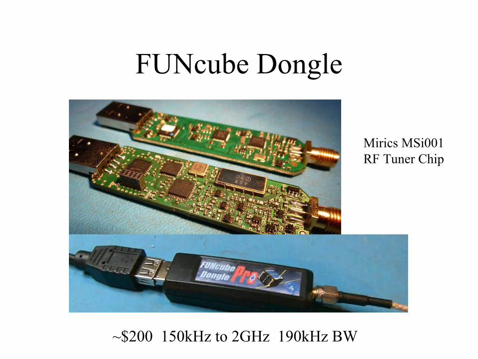
FUNcube Dongle
~$200 150kHz to 2GHz 190kHz BW
Mirics MSi001RF Tuner Chip
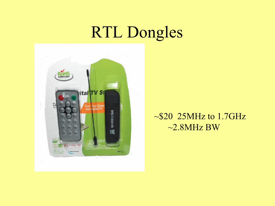
RTL Dongles
~$20 25MHz to 1.7GHz~2.8MHz BW
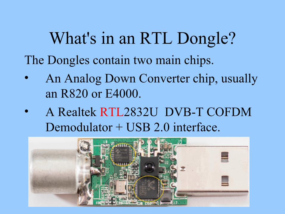
What's in an RTL Dongle?The Dongles contain two main chips.
• An Analog Down Converter chip, usually an R820 or E4000.
• A Realtek RTL2832U DVB-T COFDM Demodulator + USB 2.0 interface.
Limitations of the RTL Dongle
• Frequency controlled by simple crystal with no temperature compensation.
• Frequency PLL step size ~1kHz or so.
• No RF filtering so easily overloaded by just about any strong signal.
• The USB interface limited to 8 bits I/Q so Gain Control is required.
The Interesting Part
• The RTL2832 chip is primarily a DTV demodulator chip so is not much use for general reception except for the raw I/Q mode which has major limitations.
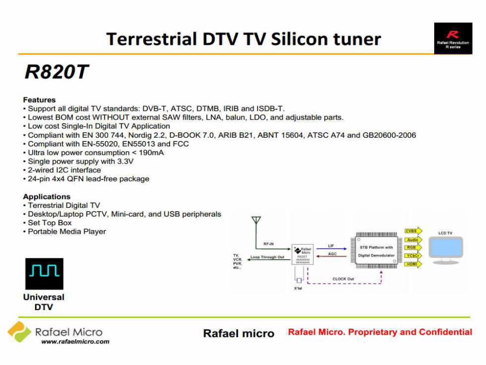
• The Rafael Micro R820 chip is generic and is just a programmable analog RF down converter. It looked like it could be a very useful building block.
• Very limited technical information on this chip so could it be integrated in a custom design?
Down Converter Design Goals
• Improve dynamic performance with some RF Filtering.
• Be able to lock the frequency to a 10MHz GPS reference.
• Have 1 Hz frequency resolution.
• Get maximum IF BW around 8MHz
• Find a source and info for the R820 chip.
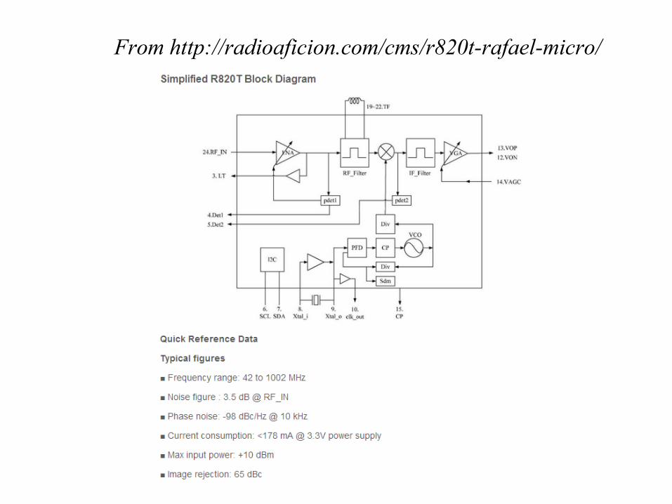
From http://radioaficion.com/cms/r820t-rafael-micro/
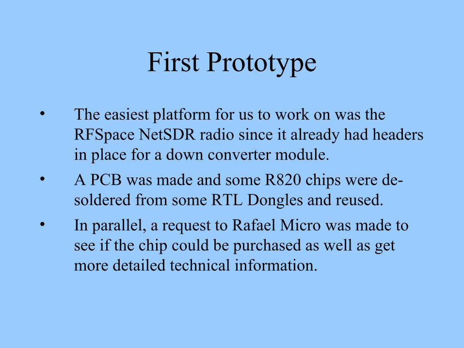
First Prototype
• The easiest platform for us to work on was the RFSpace NetSDR radio since it already had headers in place for a down converter module.
• A PCB was made and some R820 chips were de-soldered from some RTL Dongles and reused.
• In parallel, a request to Rafael Micro was made to see if the chip could be purchased as well as get more detailed technical information.
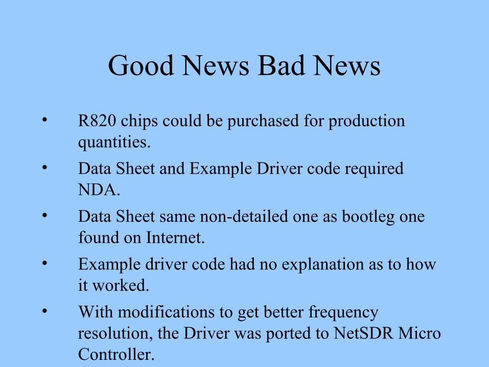
Good News Bad News
• R820 chips could be purchased for production quantities.
• Data Sheet and Example Driver code required NDA.
• Data Sheet same non-detailed one as bootleg one found on Internet.
• Example driver code had no explanation as to how it worked.
• With modifications to get better frequency resolution, the Driver was ported to NetSDR Micro Controller.
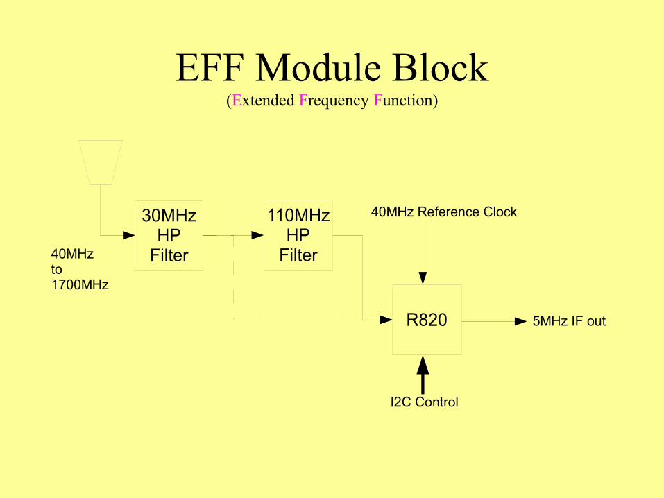
EFF Module Block(Extended Frequency Function)
30MHzHP
Filter
110MHzHP
Filter
R820
40MHz Reference Clock
I2C Control
5MHz IF out
40MHzto1700MHz
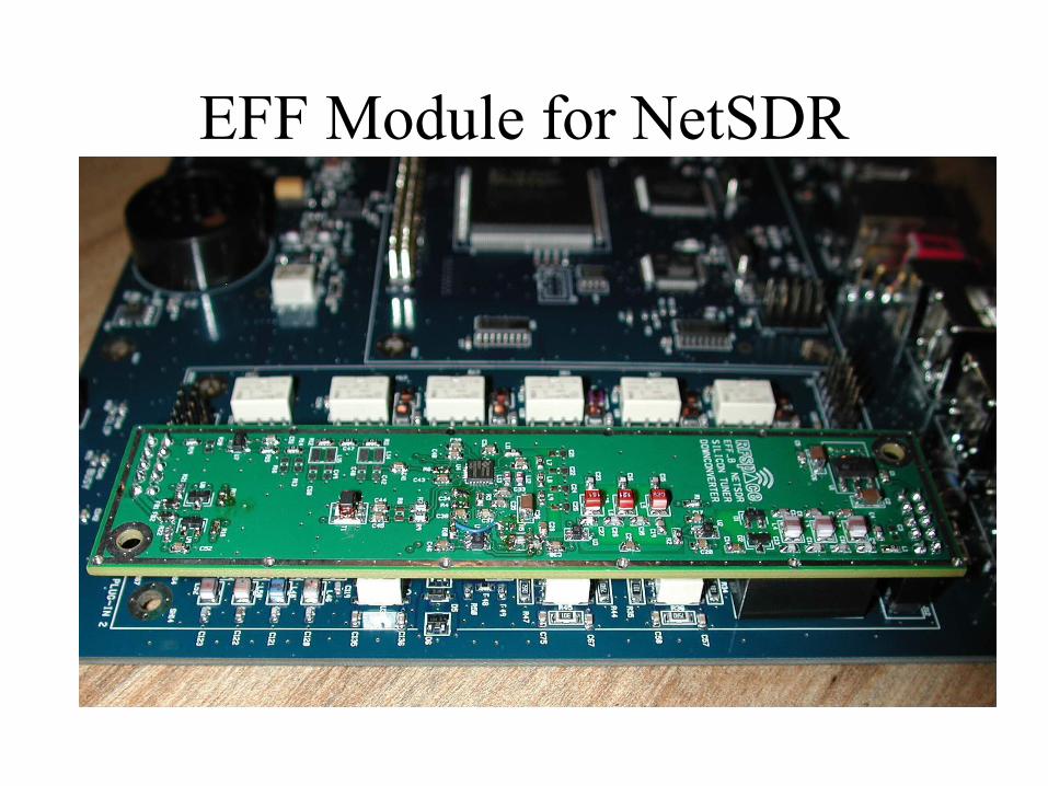
EFF Module for NetSDR
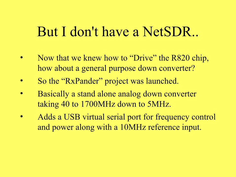
But I don't have a NetSDR..
• Now that we knew how to “Drive” the R820 chip, how about a general purpose down converter?
• So the “RxPander” project was launched.
• Basically a stand alone analog down converter taking 40 to 1700MHz down to 5MHz.
• Adds a USB virtual serial port for frequency control and power along with a 10MHz reference input.
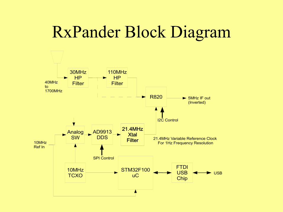
RxPander Block Diagram
30MHzHP
Filter
110MHzHP
Filter
R820
21.4MHz Variable Reference Clock For 1Hz Frequency Resolution
I2C Control
5MHz IF out(Inverted)
40MHzto1700MHz
AD9913DDS
21.4MHzXtalFilter
10MHzTCXO
STM32F100uC
21.4MHzXtalFilter10MHz
Ref In
AnalogSW
FTDIUSBChip
USB
SPI Control
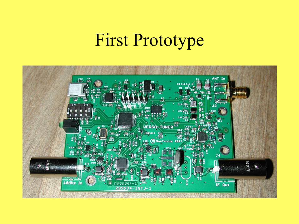
First Prototype
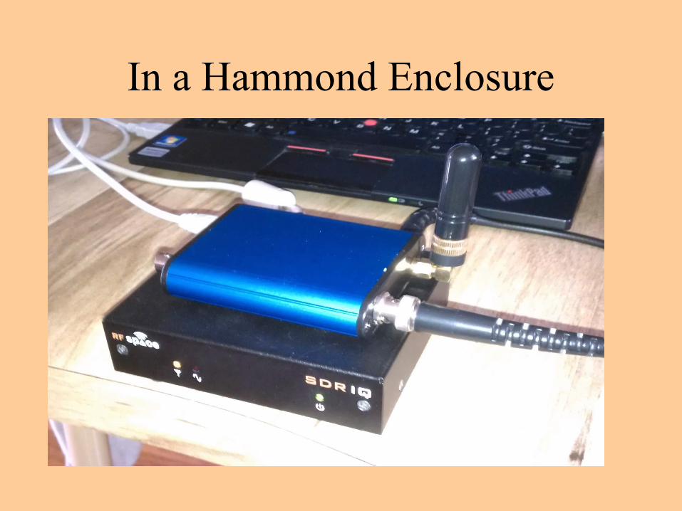
In a Hammond Enclosure
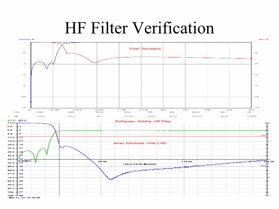
HF Filter Verification
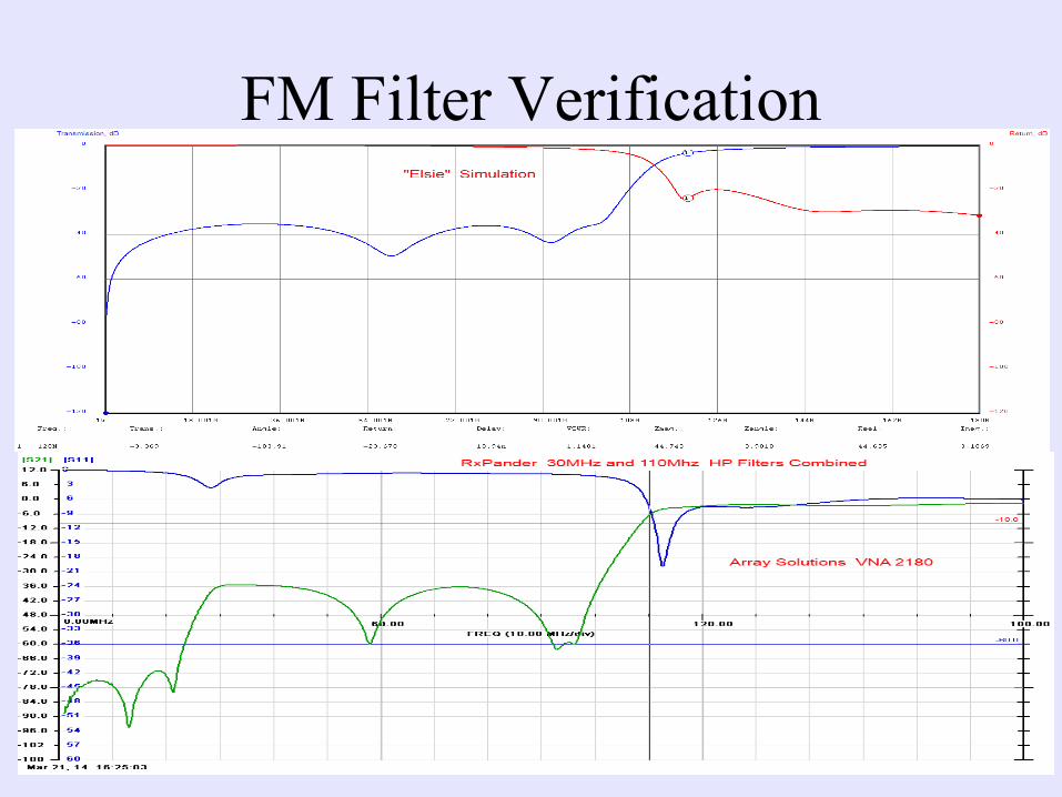
FM Filter Verification
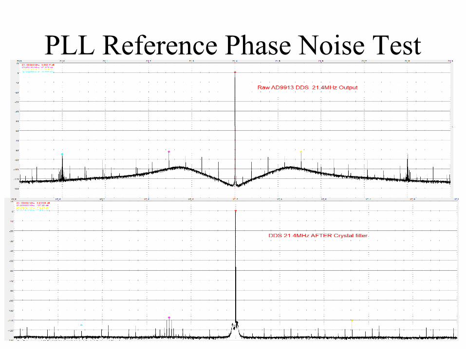
PLL Reference Phase Noise Test
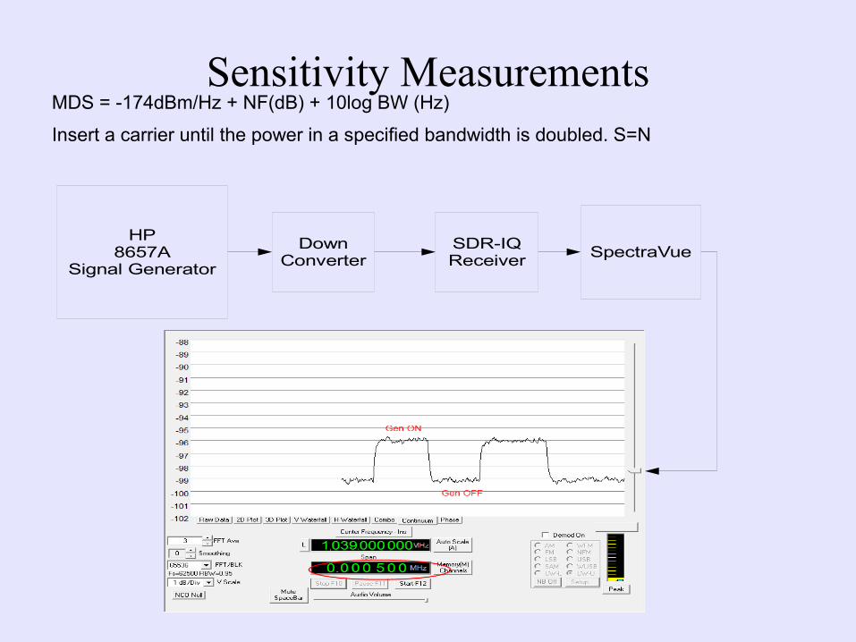
Sensitivity MeasurementsMDS = -174dBm/Hz + NF(dB) + 10log BW (Hz)
Insert a carrier until the power in a specified bandwidth is doubled. S=N
HP8657A
Signal Generator
DownConverter
SDR-IQReceiver
SpectraVue
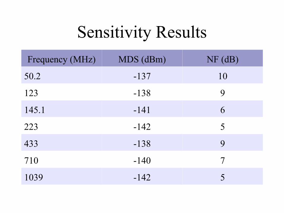
Sensitivity Results
Frequency (MHz) MDS (dBm) NF (dB)
50.2 -137 10
123 -138 9
145.1 -141 6
223 -142 5
433 -138 9
710 -140 7
1039 -142 5
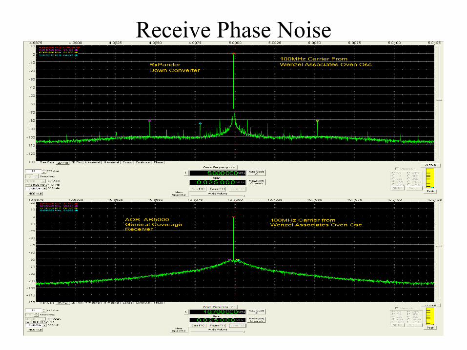
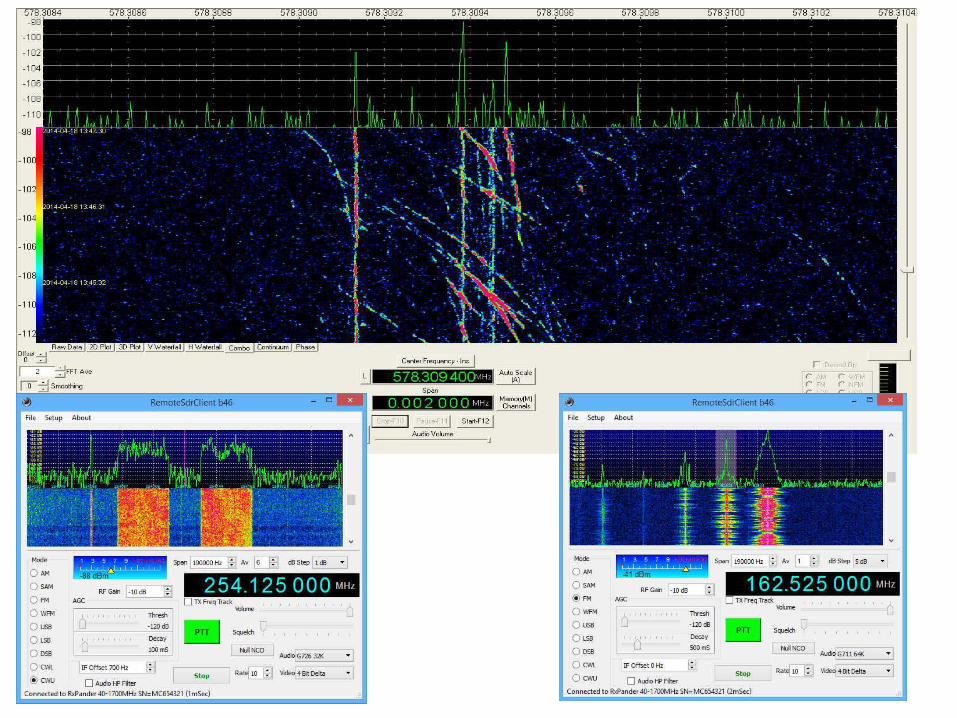
Receive Phase Noise
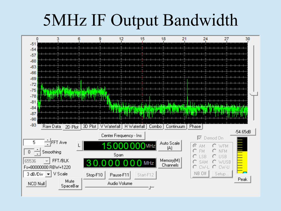
5MHz IF Output Bandwidth
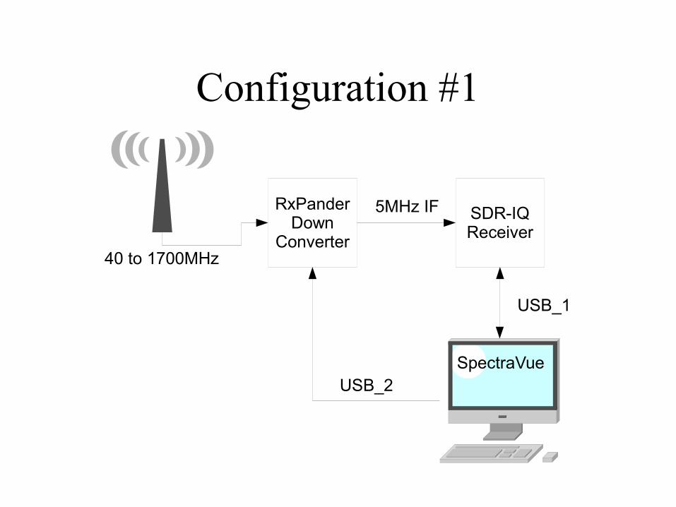
Configuration #1
RxPanderDown
Converter
SDR-IQReceiver
USB_1
USB_2SpectraVue
5MHz IF
40 to 1700MHz
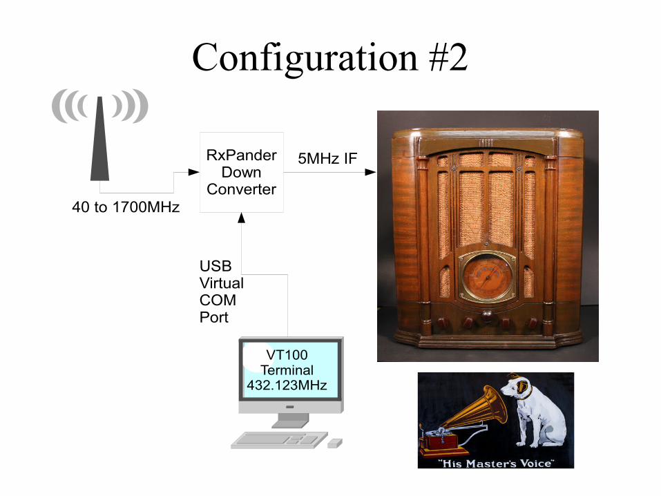
Configuration #2
RxPanderDown
Converter
USBVirtual COMPort
VT100Terminal
432.123MHz
5MHz IF
40 to 1700MHz
To Do's
• Fix some PCB issues.
• Fix FM filter return loss
• See if able to make board ~$100 MSRP
• Layout for different TCXO
• Make small run to see if viable product.

More Info:
(www.moetronix.com/RxPander) Will eventually have more information as this develops.