Embed Size (px)
Citation preview
Verification of Large-Scale On-Chip Power Grids
Xuanxing Xiong Illinois Institute of Technology Chicago, Illinois, United States April, 2013

Slide 2
Agenda
Background
Parallel Transient Simulation
Vectorless Verification Steady-State Verification Transient Verification
Conclusion
Slide 3
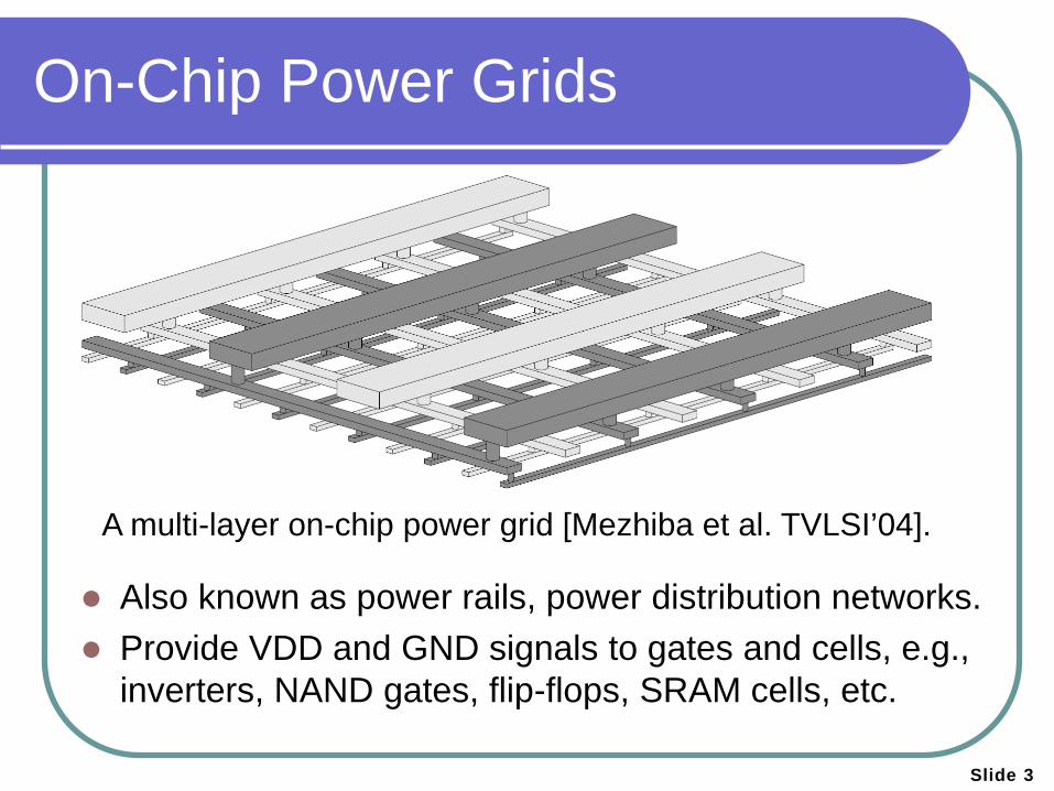
On-Chip Power Grids
Also known as power rails, power distribution networks. Provide VDD and GND signals to gates and cells, e.g.,
inverters, NAND gates, flip-flops, SRAM cells, etc.
A multi-layer on-chip power grid [Mezhiba et al. TVLSI’04].
Slide 4
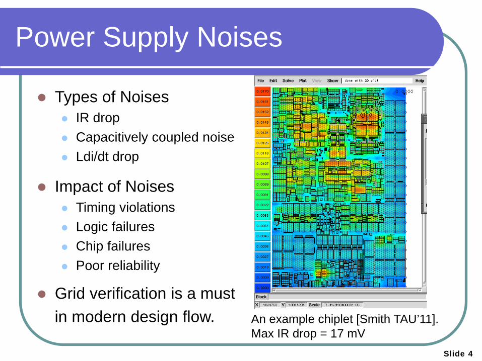
Power Supply Noises
Types of Noises IR drop Capacitively coupled noise Ldi/dt drop
Impact of Noises Timing violations Logic failures Chip failures Poor reliability
Grid verification is a must in modern design flow.
An example chiplet [Smith TAU’11]. Max IR drop = 17 mV
Slide 5
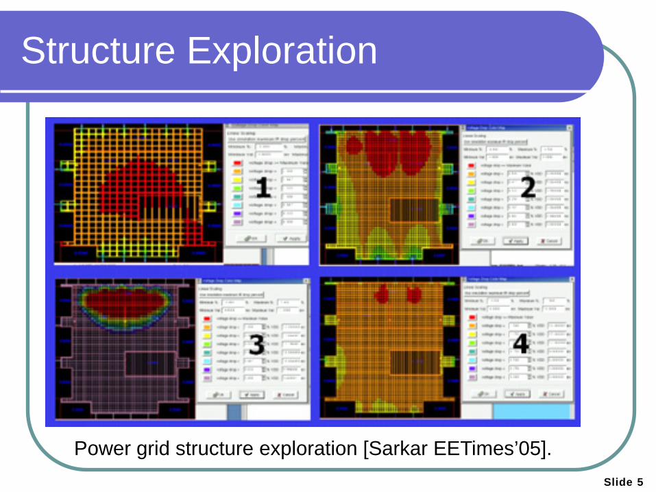
Structure Exploration
Power grid structure exploration [Sarkar EETimes’05].
Slide 6
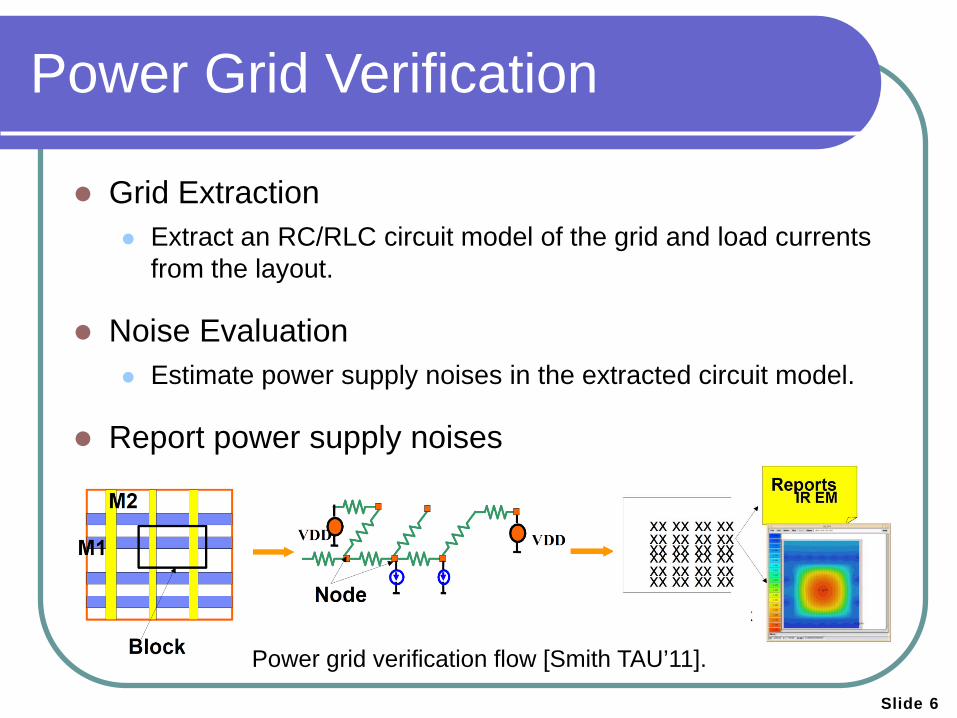
Power Grid Verification
Grid Extraction Extract an RC/RLC circuit model of the grid and load currents
from the layout.
Noise Evaluation Estimate power supply noises in the extracted circuit model.
Report power supply noises
Power grid verification flow [Smith TAU’11].
Slide 7
Methodology
Verify that the power supply noises are within certain acceptable range Noises depend on the patterns of currents drawn
General idea for power grid verification First, specify currents Second, compute noises
Simulation-based verification DC & Transient analysis Use current excitations extracted from the circuit Mainstream technique for sign-off verification of power grids
Power Grid Analysis
General circuit simulation tools (e.g. SPICE) are inefficient for power grid analysis because of extreme time and memory complexity.
Many algorithms have been developed, e.g. Preconditioned Conjugate Gradient (PCG) [Chen et al. DAC’01] Multigrid Method [Kozhaya et al. TCAD’02] Hierarchical Algorithm [Zhao et al. TCAD’02] Random Walk Approach [Qian et al. TCAD’05] Sparse Approximate Inverse Technique [Cauley et al. TCAD’10]
Challenges Handle large-scale power grids Parallel implementation
Slide 8
Limitations of Simulation
Need to simulate a large number of current vectors to cover usual use scenarios
No guarantee the worst noise (but not overpessimistic) can be found.
Does not allow early power grid verfication Needs specific circuit implementations for current vector
extraction Can only be performed after the circuit design is done But early power grid verification is preferred for ease of grid
modification
Remains mainsteam technique for sign-off verification of power grids
Slide 9
Vectorless Verification
[Kouroussis et al. DAC’03] and [Abdul Ghani et al. ICCAD’06]
Objective Evaluate the worst-case voltage noise without enumerating
all possible current vectors
Methodology Model all possible current vectors by a feasible set Solve an optimziation problem that maximizes the voltage
noise within the feasible set
Challenges Optimization usually consumes more resources,
especially for large power grids
Slide 10
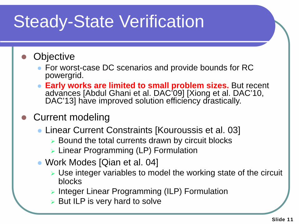
Steady-State Verification
Objective For worst-case DC scenarios and provide bounds for RC
powergrid. Early works are limited to small problem sizes. But recent
advances [Abdul Ghani et al. DAC’09] [Xiong et al. DAC’10, DAC’13] have improved solution efficiency drastically.
Current modeling Linear Current Constraints [Kouroussis et al. 03]
Bound the total currents drawn by circuit blocks Linear Programming (LP) Formulation
Work Modes [Qian et al. 04] Use integer variables to model the working state of the circuit
blocks Integer Linear Programming (ILP) Formulation But ILP is very hard to solve
Slide 11
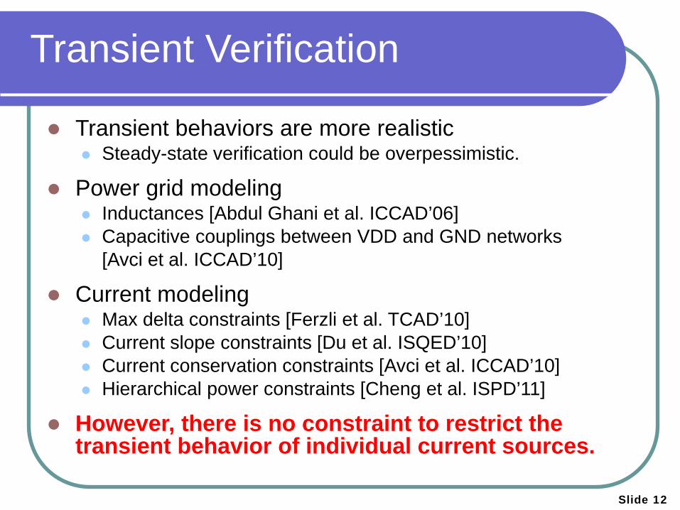
Transient Verification
Transient behaviors are more realistic Steady-state verification could be overpessimistic.
Power grid modeling Inductances [Abdul Ghani et al. ICCAD’06] Capacitive couplings between VDD and GND networks [Avci et al. ICCAD’10]
Current modeling Max delta constraints [Ferzli et al. TCAD’10] Current slope constraints [Du et al. ISQED’10] Current conservation constraints [Avci et al. ICCAD’10] Hierarchical power constraints [Cheng et al. ISPD’11]
However, there is no constraint to restrict the transient behavior of individual current sources.
Slide 12
Slide 13
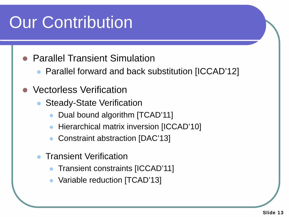
Our Contribution
Parallel Transient Simulation Parallel forward and back substitution [ICCAD’12]
Vectorless Verification Steady-State Verification
Dual bound algorithm [TCAD’11] Hierarchical matrix inversion [ICCAD’10] Constraint abstraction [DAC’13]
Transient Verification Transient constraints [ICCAD’11] Variable reduction [TCAD’13]
Slide 14
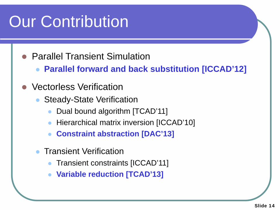
Our Contribution
Parallel Transient Simulation Parallel forward and back substitution [ICCAD’12]
Vectorless Verification Steady-State Verification
Dual bound algorithm [TCAD’11] Hierarchical matrix inversion [ICCAD’10] Constraint abstraction [DAC’13]
Transient Verification Transient constraints [ICCAD’11] Variable reduction [TCAD’13]
Slide 15
Agenda
Background
Parallel Transient Simulation [ICCAD’12]
Vectorless Verification Steady-State Verification Transient Verification
Conclusion
Slide 16
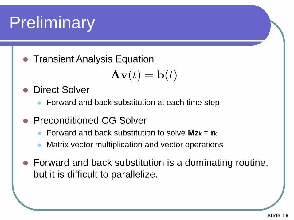
Preliminary
Transient Analysis Equation Direct Solver
Forward and back substitution at each time step
Preconditioned CG Solver Forward and back substitution to solve Mzk = rk
Matrix vector multiplication and vector operations
Forward and back substitution is a dominating routine, but it is difficult to parallelize.
Slide 17
Parallel Forward & Back Sub.
[Gupta et al SC’95]
A post-factorization approach Supernode-based parallelization according to the
elimination tree Achieve weak performance scaling using up to 256
processors with multiple right-hand-side (RHS) vectors (e.g., 30)
However, it is often difficult to form supernodes for power grid transient analysis, and we only have a single RHS vector at each time step.
Slide 18
Levelized Parallelization
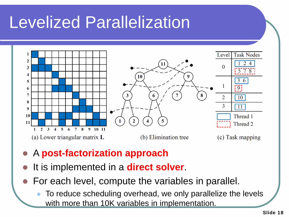
A post-factorization approach It is implemented in a direct solver. For each level, compute the variables in parallel.
To reduce scheduling overhead, we only parallelize the levels with more than 10K variables in implementation.
Slide 19
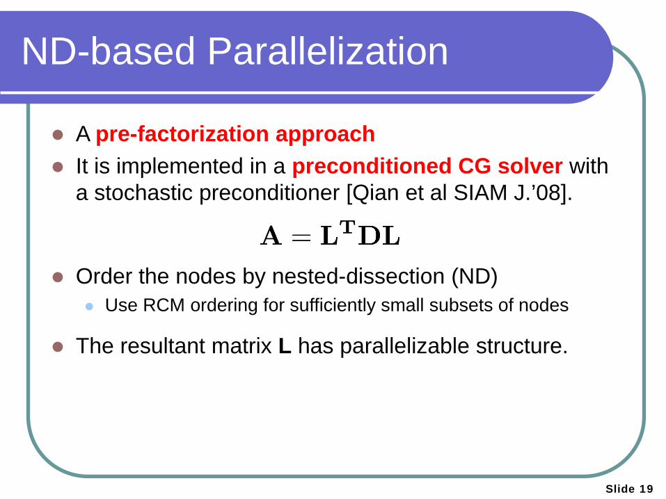
ND-based Parallelization
A pre-factorization approach It is implemented in a preconditioned CG solver with
a stochastic preconditioner [Qian et al SIAM J.’08].
Order the nodes by nested-dissection (ND) Use RCM ordering for sufficiently small subsets of nodes
The resultant matrix L has parallelizable structure.
Slide 20
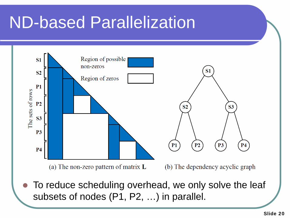
ND-based Parallelization
To reduce scheduling overhead, we only solve the leaf
subsets of nodes (P1, P2, …) in parallel.
Slide 21
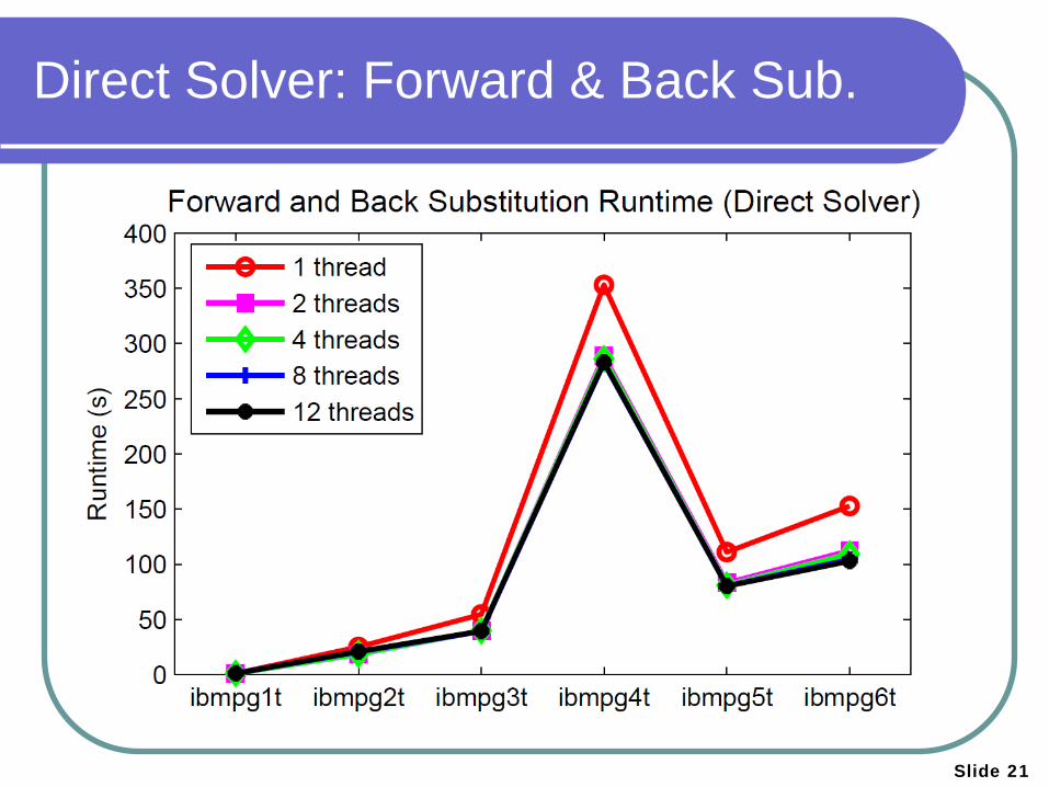
Direct Solver: Forward & Back Sub.
Slide 22
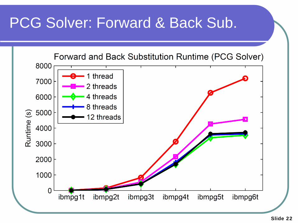
PCG Solver: Forward & Back Sub.
Slide 23
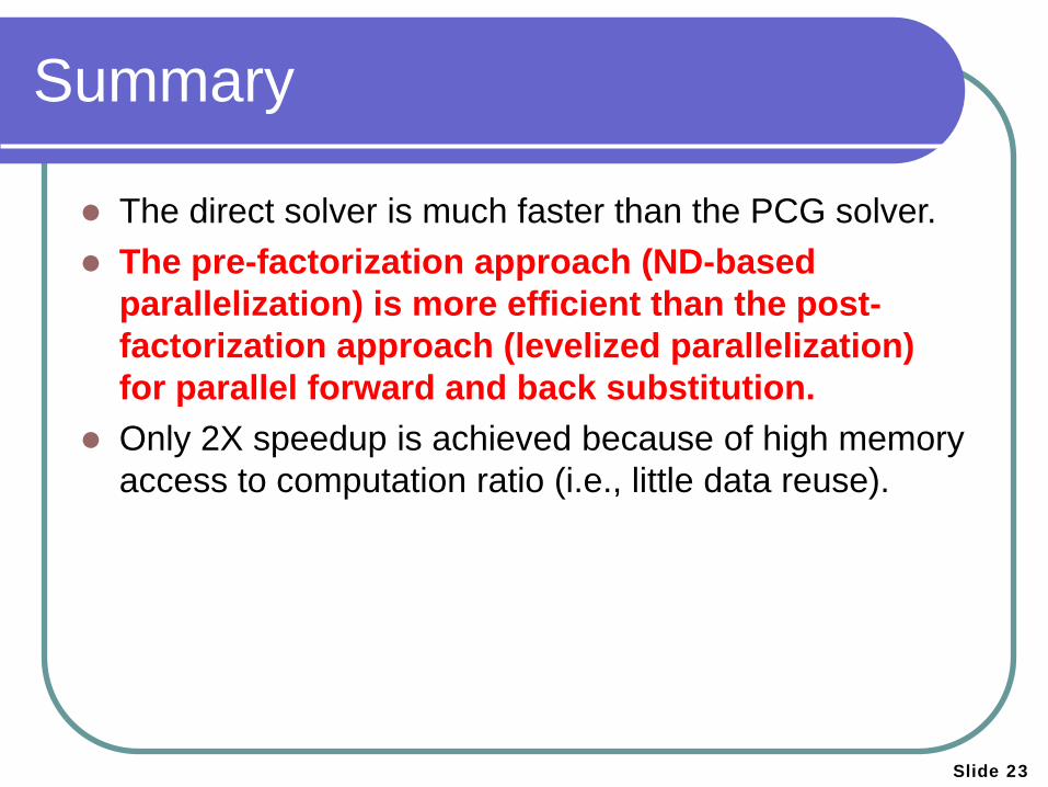
Summary
The direct solver is much faster than the PCG solver. The pre-factorization approach (ND-based
parallelization) is more efficient than the post-factorization approach (levelized parallelization) for parallel forward and back substitution.
Only 2X speedup is achieved because of high memory access to computation ratio (i.e., little data reuse).
Slide 24
Agenda
Background
Parallel Transient Simulation
Vectorless Verification Steady-State Verification
Preliminary Constraint Abstraction
Transient Verification
Conclusion
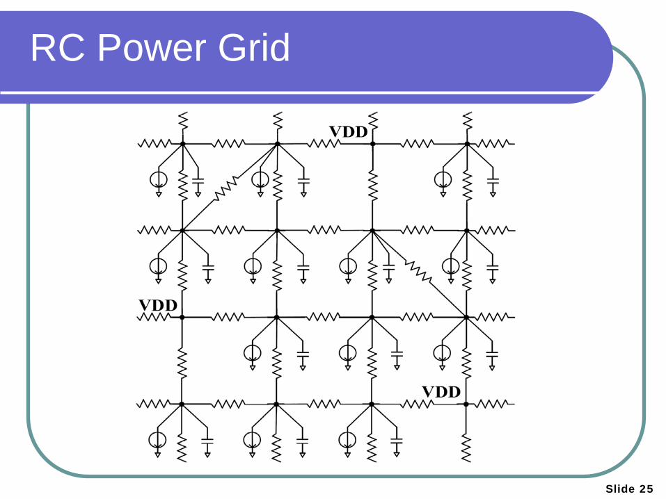
RC Power Grid
Slide 25
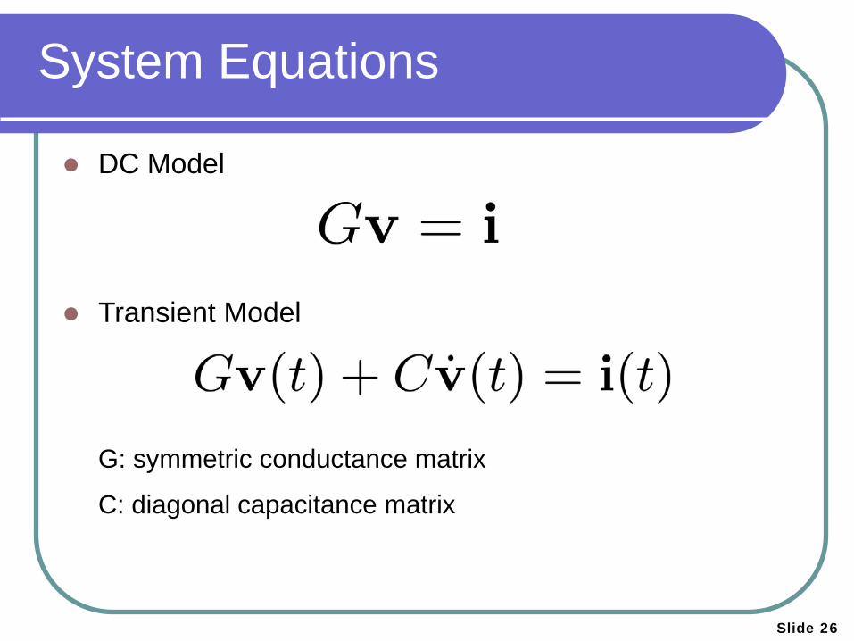
System Equations
DC Model
Transient Model
G: symmetric conductance matrix
C: diagonal capacitance matrix
Slide 26
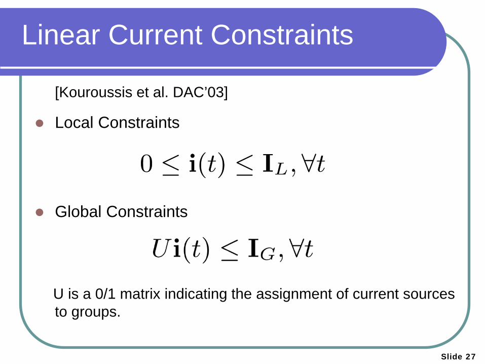
Linear Current Constraints
[Kouroussis et al. DAC’03]
Local Constraints
Global Constraints
U is a 0/1 matrix indicating the assignment of current sources to groups.
Slide 27
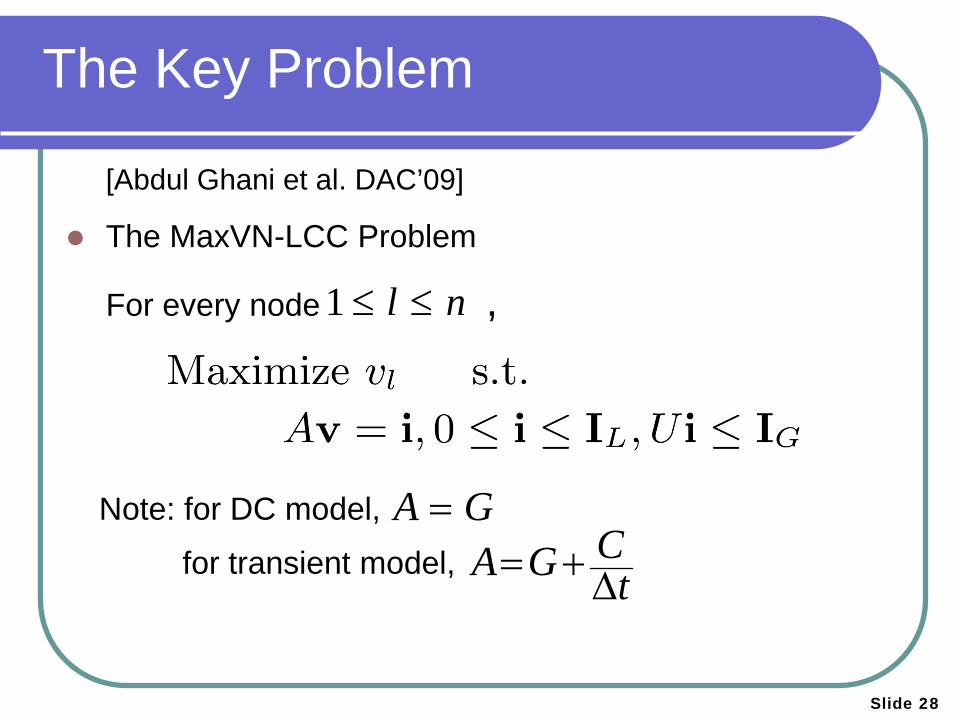
The Key Problem
[Abdul Ghani et al. DAC’09]
The MaxVN-LCC Problem
For every node ,
1 l n≤ ≤
A G=CA G t= +∆
for transient model,
Note: for DC model,
Slide 28
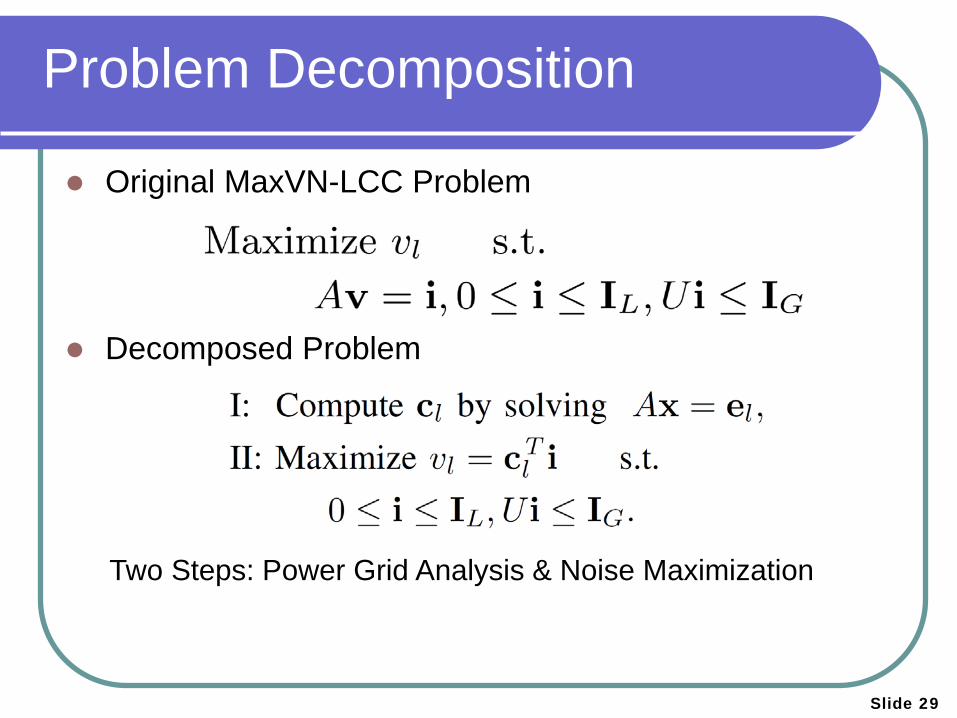
Original MaxVN-LCC Problem
Decomposed Problem
Two Steps: Power Grid Analysis & Noise Maximization
Problem Decomposition
Slide 29
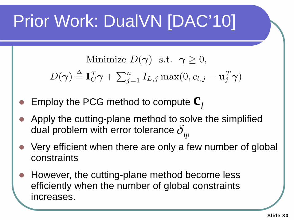
Employ the PCG method to compute
Apply the cutting-plane method to solve the simplified dual problem with error tolerance
Very efficient when there are only a few number of global constraints
However, the cutting-plane method become less efficiently when the number of global constraints increases.
Prior Work: DualVN [DAC’10]
lpδ
lc
Slide 30
lpδ
Slide 31
Agenda
Background
Parallel Transient Simulation
Vectorless Verification Steady-State Verification
Preliminary Constraint Abstraction [DAC’13]
Transient Verification
Conclusion

Divide and Conquer ?
Slide 32
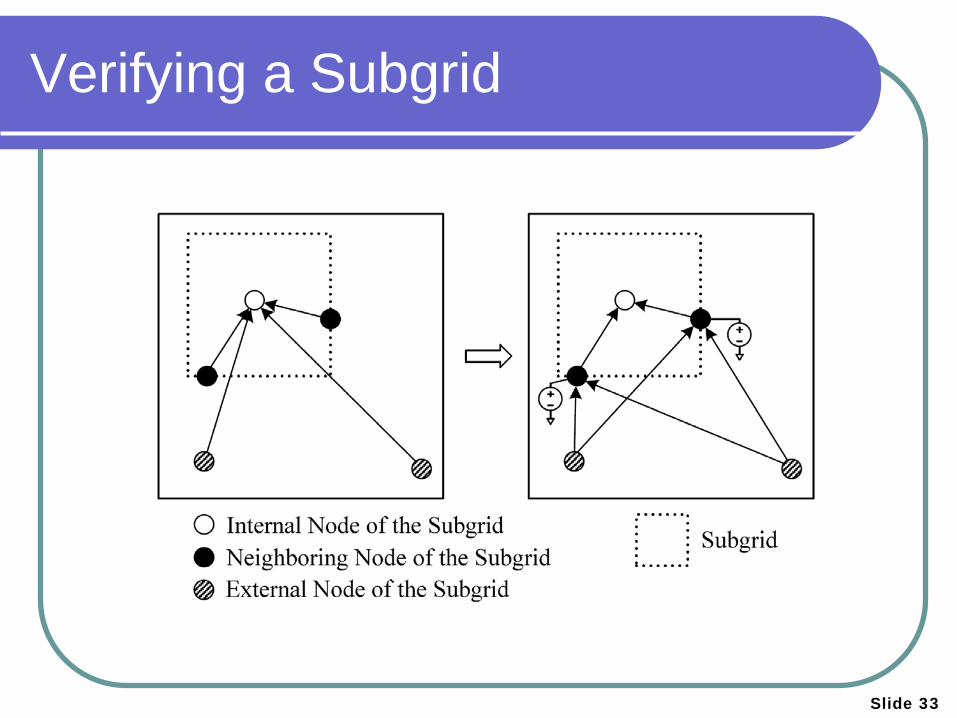
Verifying a Subgrid
Slide 33
Slide 34
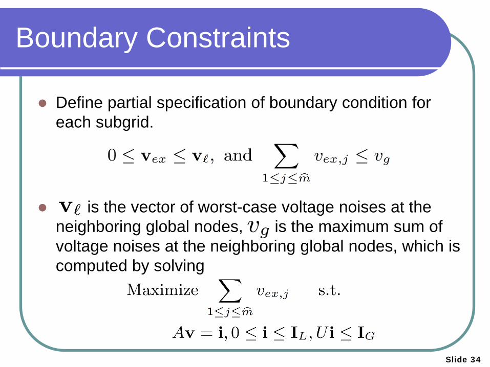
Boundary Constraints
Define partial specification of boundary condition for each subgrid.
is the vector of worst-case voltage noises at the neighboring global nodes, is the maximum sum of voltage noises at the neighboring global nodes, which is computed by solving
Slide 35
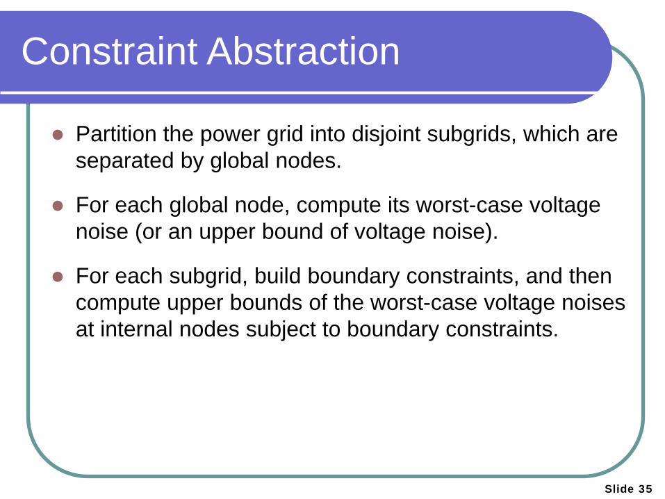
Constraint Abstraction
Partition the power grid into disjoint subgrids, which are separated by global nodes.
For each global node, compute its worst-case voltage noise (or an upper bound of voltage noise).
For each subgrid, build boundary constraints, and then compute upper bounds of the worst-case voltage noises at internal nodes subject to boundary constraints.
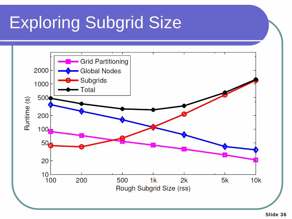
Slide 36
Exploring Subgrid Size
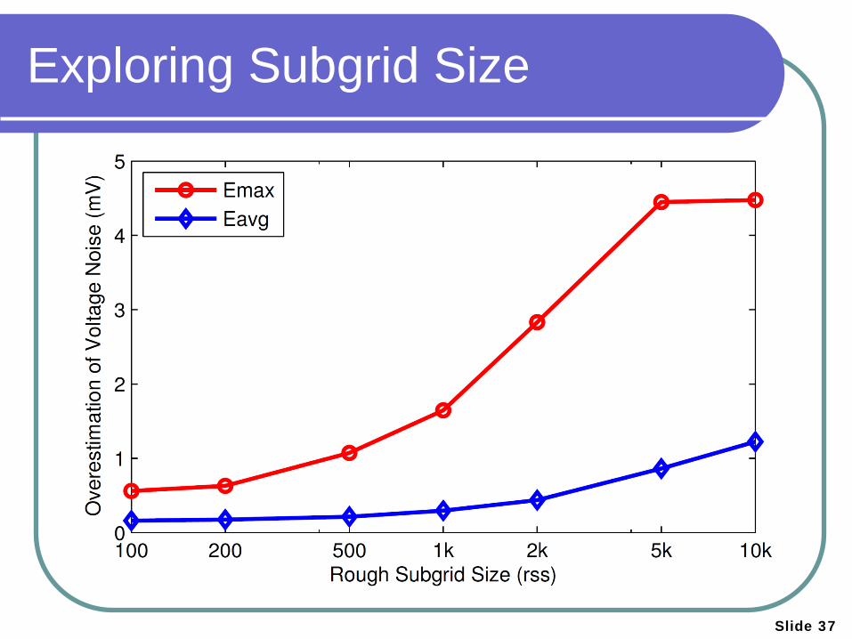
Slide 37
Exploring Subgrid Size
Slide 38
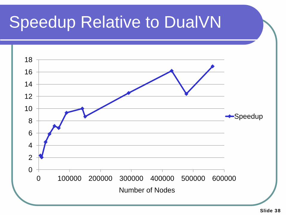
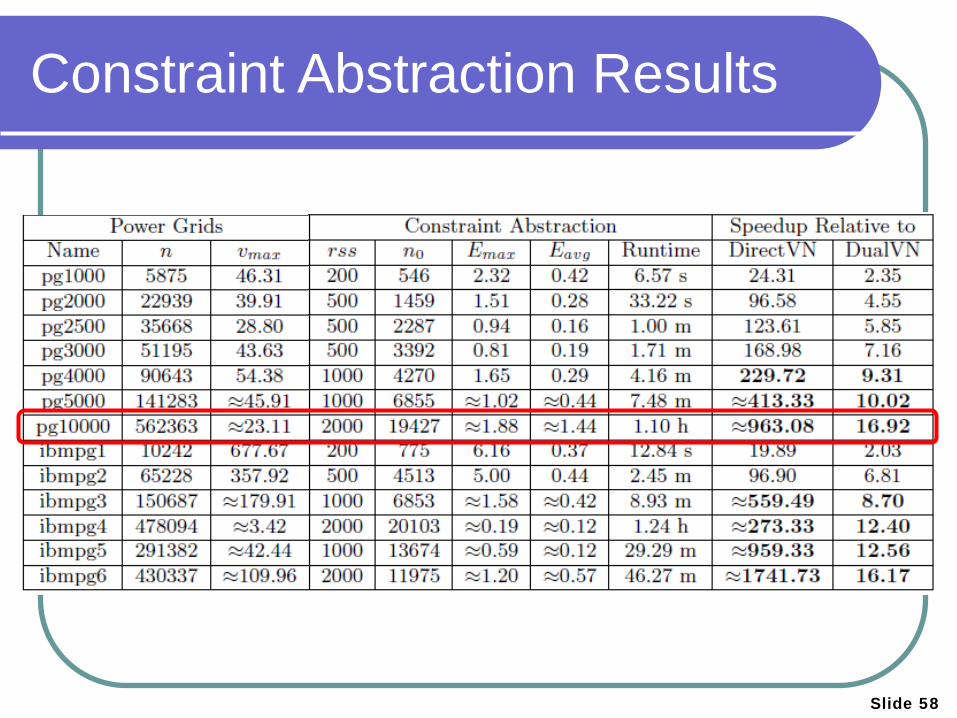
Speedup Relative to DualVN
0
2
4
6
8
10
12
14
16
18
0 100000 200000 300000 400000 500000 600000
Speedup
Number of Nodes
Slide 39
Agenda
Background
Parallel Transient Simulation
Vectorless Verification Steady-State Verification Transient Verification [TCAD’13]
Conclusion
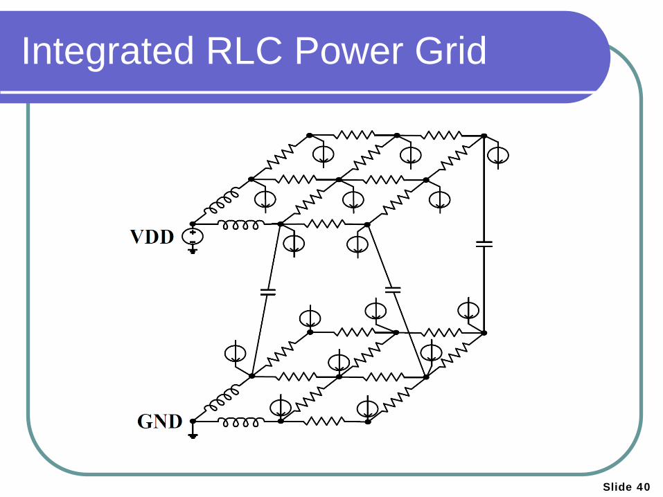
Integrated RLC Power Grid
Slide 40
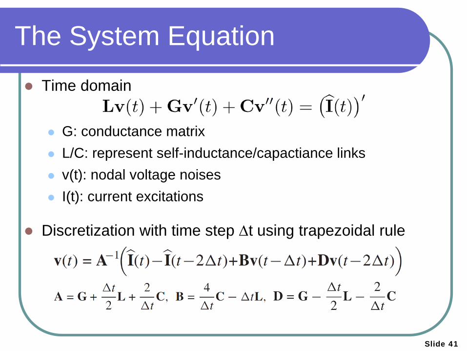
The System Equation
Time domain G: conductance matrix L/C: represent self-inductance/capactiance links v(t): nodal voltage noises I(t): current excitations
Discretization with time step ∆t using trapezoidal rule
^
Slide 41
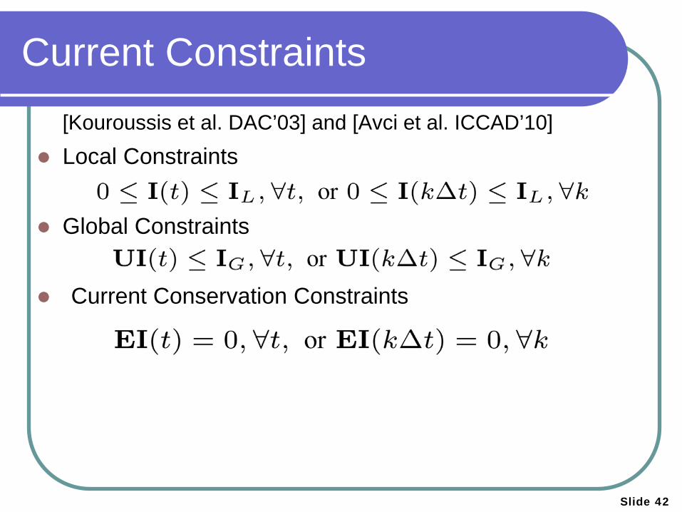
Current Constraints [Kouroussis et al. DAC’03] and [Avci et al. ICCAD’10] Local Constraints Global Constraints Current Conservation Constraints
Slide 42
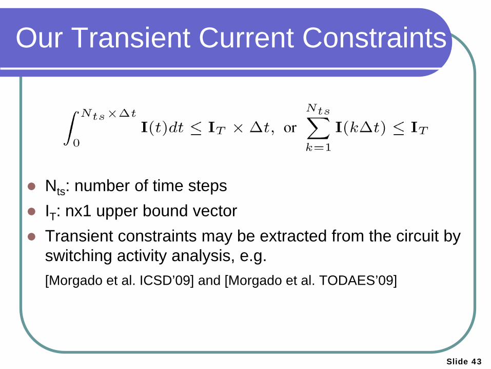
Our Transient Current Constraints
Nts: number of time steps IT: nx1 upper bound vector Transient constraints may be extracted from the circuit by
switching activity analysis, e.g. [Morgado et al. ICSD’09] and [Morgado et al. TODAES’09]
Slide 43
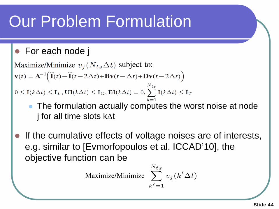
Our Problem Formulation
For each node j The formulation actually computes the worst noise at node
j for all time slots k∆t
If the cumulative effects of voltage noises are of interests, e.g. similar to [Evmorfopoulos et al. ICCAD’10], the objective function can be
Slide 44
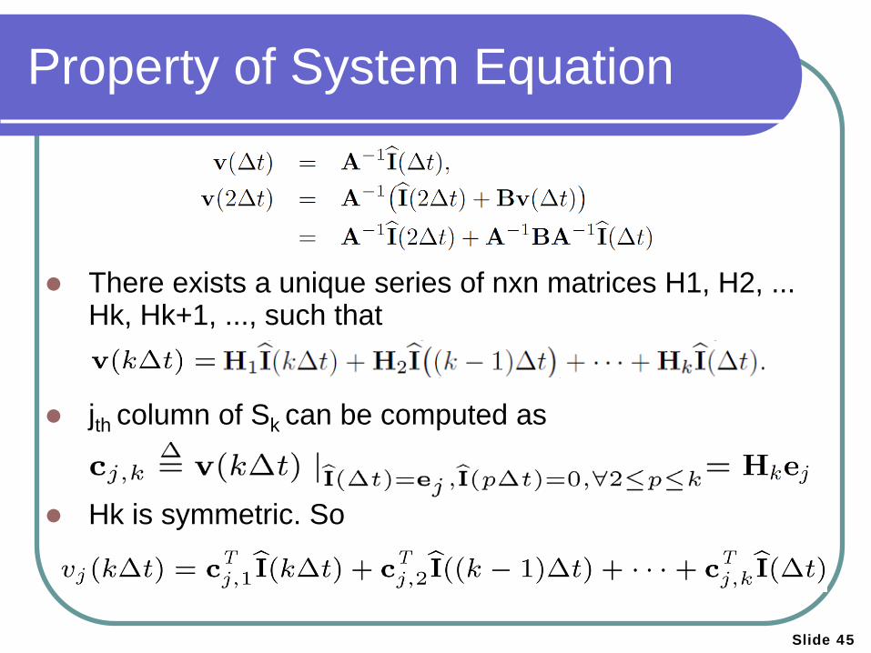
There exists a unique series of nxn matrices H1, H2, ... Hk, Hk+1, ..., such that
jth column of Sk can be computed as
Hk is symmetric. So
Property of System Equation
Slide 45
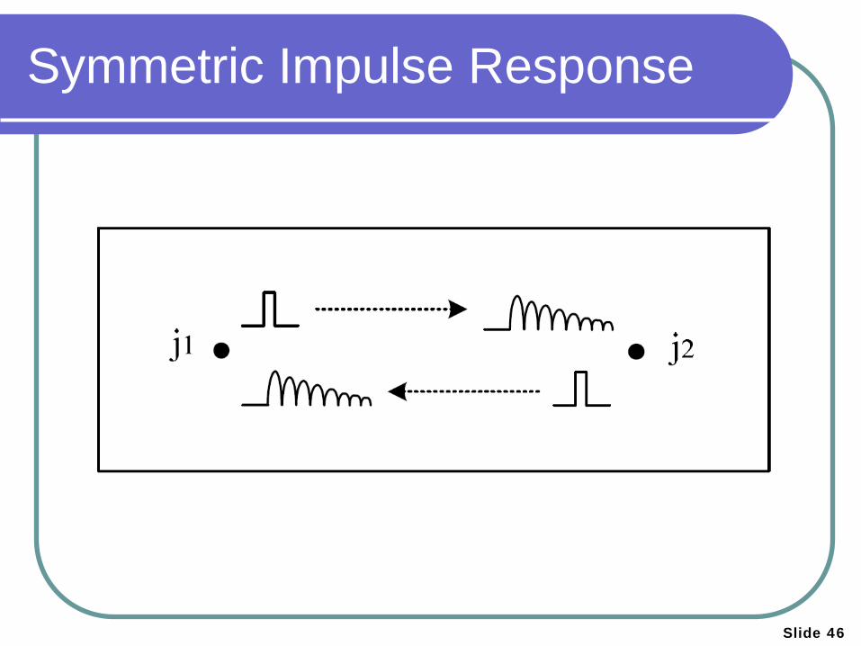
Symmetric Impulse Response
Slide 46
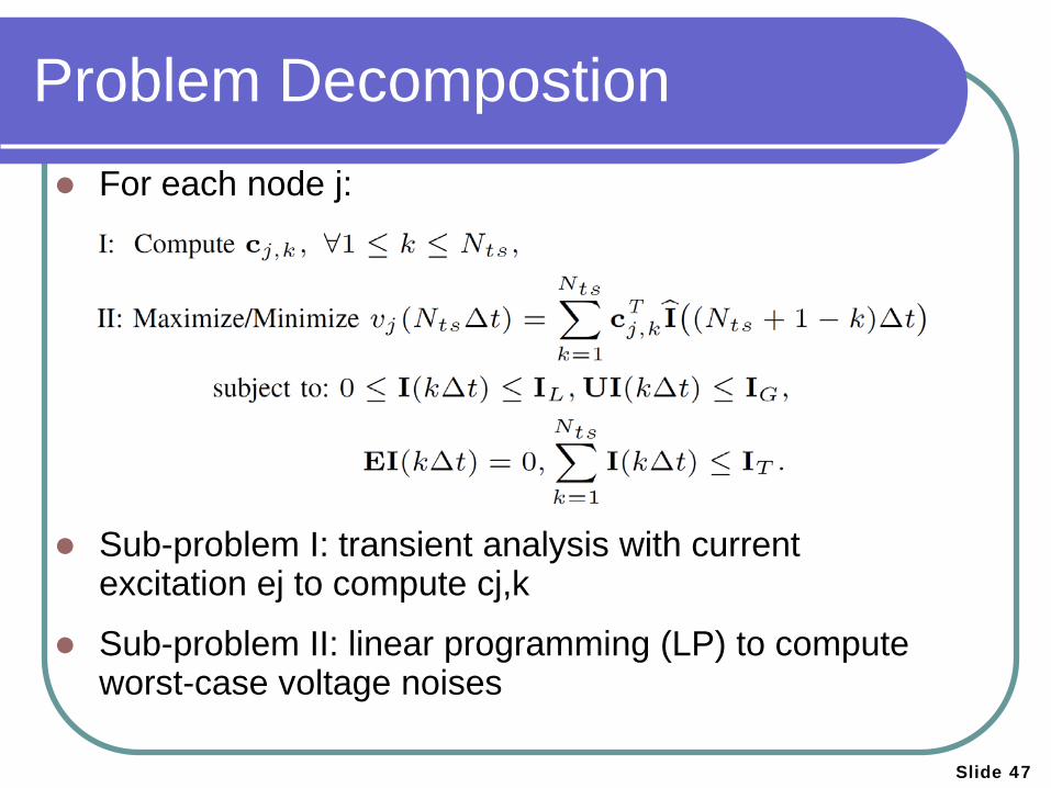
Problem Decompostion For each node j:
Sub-problem I: transient analysis with current excitation ej to compute cj,k
Sub-problem II: linear programming (LP) to compute worst-case voltage noises
Slide 47
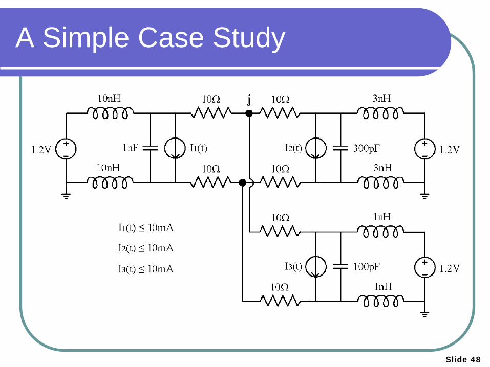
A Simple Case Study
Slide 48
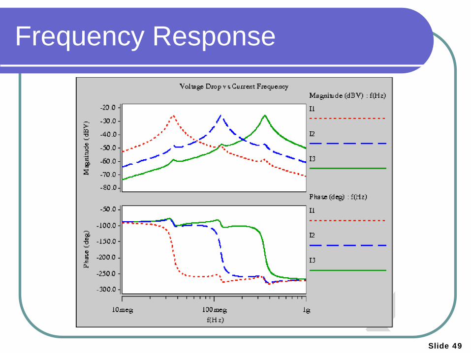
Frequency Response
Slide 49
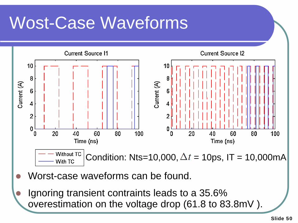
Wost-Case Waveforms
Condition: Nts=10,000, = 10ps, IT = 10,000mA
Slide 50
Worst-case waveforms can be found.
Ignoring transient contraints leads to a 35.6% overestimation on the voltage drop (61.8 to 83.8mV ).
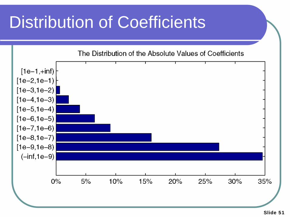
Distribution of Coefficients
Slide 51
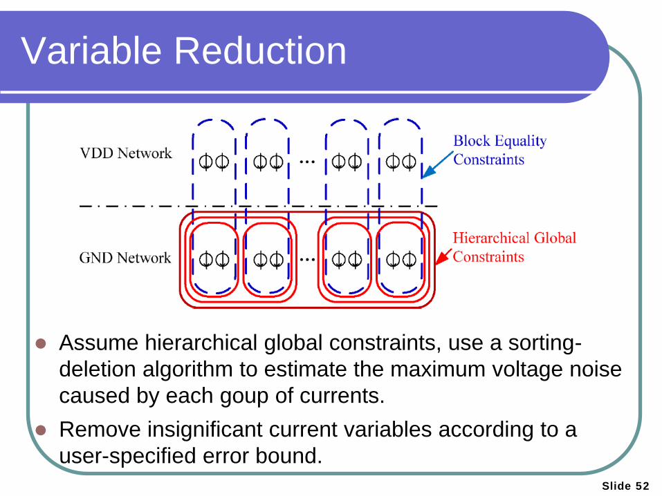
Variable Reduction
Slide 52
Assume hierarchical global constraints, use a sorting-deletion algorithm to estimate the maximum voltage noise caused by each goup of currents.
Remove insignificant current variables according to a user-specified error bound.
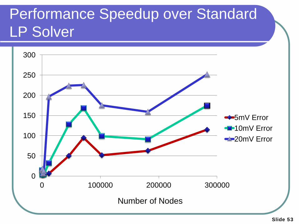
Performance Speedup over Standard LP Solver
Slide 53
0
50
100
150
200
250
300
0 100000 200000 300000
5mV Error 10mV Error 20mV Error
Number of Nodes
Slide 54
Agenda
Background
Parallel Transient Simulation
Vectorless Verification Steady-State Verification Transient Verification
Conclusion

Slide 55
Conclusion
Investigated parallel forward and back substitution algorithms for power grid transient simulation.
Proposed novel algorithms to speedup vectorless steady-state verification for up to 17X.
Proposed efficient approach for vectorless transient verification with novel transient current constraints.
Slide 56
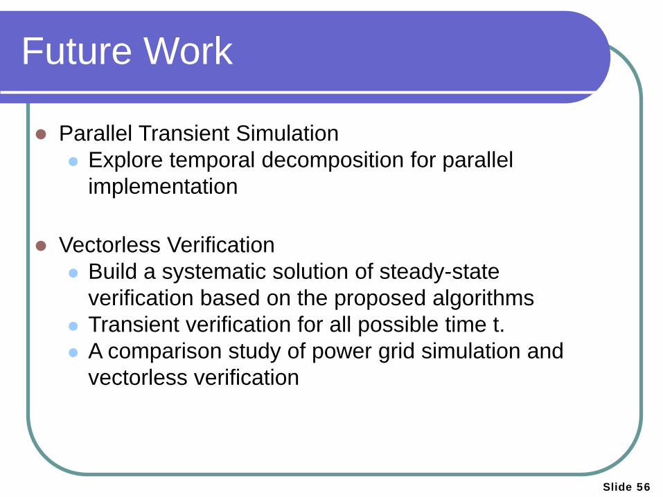
Future Work
Parallel Transient Simulation Explore temporal decomposition for parallel
implementation
Vectorless Verification Build a systematic solution of steady-state
verification based on the proposed algorithms Transient verification for all possible time t. A comparison study of power grid simulation and
vectorless verification

Slide 57
Thank You !!
Slide 58
Constraint Abstraction Results
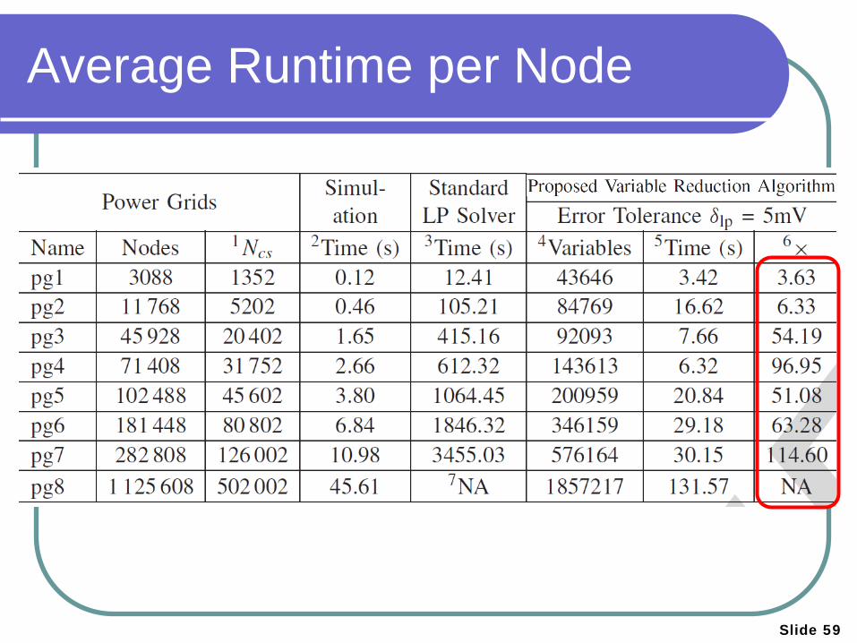
Average Runtime per Node
Slide 59
Slide 60
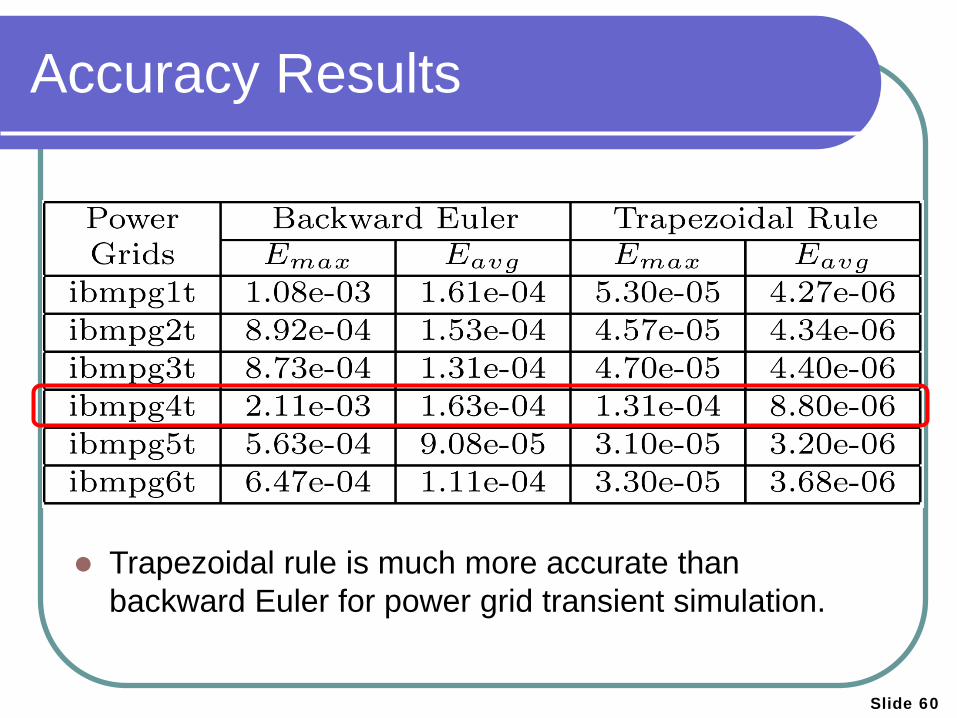
Accuracy Results
Trapezoidal rule is much more accurate than
backward Euler for power grid transient simulation.