Embed Size (px)
Citation preview

ANL/NE-14/14
Verification and Validation Plan for the SFR System Analysis Module
Nuclear Engineering Division

About Argonne National Laboratory Argonne is a U.S. Department of Energy laboratory managed by UChicago Argonne, LLC under contract DE-AC02-06CH11357. The Laboratory’s main facility is outside Chicago, at 9700 South Cass Avenue, Argonne, Illinois 60439. For information about Argonne and its pioneering science and technology programs, see www.anl.gov.
DOCUMENT AVAILABILITY
Online Access: U.S. Department of Energy (DOE) reports produced after 1991 and a growing number of pre-1991 documents are available free via DOE’s SciTech Connect (http://www.osti.gov/scitech/)
Reports not in digital format may be purchased by the public from the National Technical Information Service (NTIS):
U.S. Department of Commerce National Technical Information Service 5301 Shawnee Rd Alexandria, VA 22312 www.ntis.gov Phone: (800) 553-NTIS (6847) or (703) 605-6000 Fax: (703) 605-6900 Email: [email protected]
Reports not in digital format are available to DOE and DOE contractors from the Office of Scientific and Technical Information (OSTI):
U.S. Department of Energy Office of Scientific and Technical Information P.O. Box 62 Oak Ridge, TN 37831-0062 www.osti.gov Phone: (865) 576-8401 Fax: (865) 576-5728 Email: [email protected]
Disclaimer
This report was prepared as an account of work sponsored by an agency of the United States Government. Neither the United States
Government nor any agency thereof, nor UChicago Argonne, LLC, nor any of their employees or officers, makes any warranty, express
or implied, or assumes any legal liability or responsibility for the accuracy, completeness, or usefulness of any information, apparatus,
product, or process disclosed, or represents that its use would not infringe privately owned rights. Reference herein to any specific
commercial product, process, or service by trade name, trademark, manufacturer, or otherwise, does not necessarily constitute or imply
its endorsement, recommendation, or favoring by the United States Government or any agency thereof. The views and opinions of
document authors expressed herein do not necessarily state or reflect those of the United States Government or any agency thereof,
Argonne National Laboratory, or UChicago Argonne, LLC.

ANL/NE-14/14
prepared by Rui Hu Nuclear Engineering Division, Argonne National Laboratory November 2014
Verification and Validation Plan for the SFR System Analysis Module


Verification and Validation Plan for the SFR System Analysis Module November 2014
i ANL/NE-‐14/14
ABSTRACT
This report documents the Verification and Validation (V&V) Plan for software verification and validation of the SFR System Analysis Module (SAM), developed at Argonne National Laboratory for sodium fast reactor whole-plant transient analysis. SAM is developed under the DOE NEAMS program and is part of the Reactor Product Line toolkit. The SAM code, the phenomena and computational models of interest, the software quality assurance, and the verification and validation requirements and plans are discussed in this report.

Verification and Validation Plan for the SFR System Analysis Module November 2014
ANL/NE-‐14/14 ii

Verification and Validation Plan for the SFR System Analysis Module November 2014
iii ANL/NE-‐14/14
TABLE OF CONTENTS
Abstract ............................................................................................................................................. i Table of Contents ........................................................................................................................... iii List of Figures ................................................................................................................................. iv List of Tables .................................................................................................................................. iv Acronyms ........................................................................................................................................ v 1 Introduction ............................................................................................................................... 1
1.1 Overview of the SFR System Analysis Module ................................................................ 1 1.2 Application of Computational Model ................................................................................ 1 1.3 Users, Responsible Parties, and NEAMS Role .................................................................. 2
2 Description of the SFR System Analysis Module ..................................................................... 2 2.1 Phenomena Identification .................................................................................................. 2 2.2 Description of Physics and Empirical Models ................................................................... 3
2.2.1 Fluid dynamics ........................................................................................................ 3 2.2.2 Heat transfer ............................................................................................................ 3 2.2.3 Sodium property model and constitutive models .................................................... 4 2.2.4 Component models .................................................................................................. 4
2.3 Required Toolkit Elements and Libraries .......................................................................... 4 2.4 Consequence of Failure, Quality Rigor Level, Risk Grading ............................................ 5 2.5 Hardware and Software Platforms ..................................................................................... 6
3 Model Verification and Validation ............................................................................................ 6 3.1 Software Verification ......................................................................................................... 6
3.1.1 Software Version Control ........................................................................................ 6 3.1.2 Regression, Benchmark Tests, and Bug Reporting ................................................. 6 3.1.3 Documentation ........................................................................................................ 7 3.1.4 Static Analysis ......................................................................................................... 7 3.1.5 Verification with Analytical Benchmarks ............................................................... 7 3.1.6 Verification with Code-to-Code Comparison ......................................................... 7
3.2 Software Validation ........................................................................................................... 8 3.2.1 Unit, Component, Subsystem, System, Integral tests .............................................. 8 3.2.2 Validation Matrix and Gaps .................................................................................... 8 3.2.3 Schedule and Priorities .......................................................................................... 11
4 Sensitivity Analysis and Uncertainty Quantification .............................................................. 11 5 Path Forward ........................................................................................................................... 11 References ..................................................................................................................................... 12

Verification and Validation Plan for the SFR System Analysis Module November 2014
ANL/NE-‐14/14 iv
LIST OF FIGURES
Figure 1: Hierarchy of Experiments in a Validation Matrix ...................................................... 8
LIST OF TABLES
Table 1: List of Phenomena for Computational Model of Interest ............................................ 3 Table 2: Software Libraries Used by SAM ................................................................................ 5 Table 3: Validation Matrix for SAM ........................................................................................ 10

Verification and Validation Plan for the SFR System Analysis Module November 2014
v ANL/NE-‐14/14
ACRONYMS
ABTR Advanced Burner Test Reactor ANL Argonne National Laboratory
ARC Advanced Reactor Concepts CFD Computational Fluid Dynamics
DOE Department of Energy FFTF Fast Flux Test Facility
IEEE The Institute of Electrical and Electronics Engineers IET Integral Effects Test
LOHS Loss of Heat Sink MMS Method of Manufactured Solutions
MOOSE Multiphysics Object Oriented Simulation Environment NEAMS Nuclear Energy Advanced Modeling and Simulation
PIRT Phenomena Identification and Ranking Table QRL Quality Rigor Level
SET Separate Effects Test SFR Sodium-cooled Fast Reactor
SHRT Shutdown Heat Removal Test SQA Software Quality Assurance
SVN Subversion SVVP Software Verification and Validation Plan
PLOF Protected Loss of Flow ULOF Unprotected Loss of Flow
UQ Uncertainty Quantification V&V Verification and Validation


Verification and Validation Plan for the SFR System Analysis Module November 2014
1 ANL/NE-‐14/14
1 Introduction This Software Verification and Validation Plan (SVVP) documents the plan for software
verification and validation of the System Analysis Module (SAM) for sodium fast reactors (SFRs) [1][2]. The implementation of this plan will ensure that the SAM development conforms to applicable Institute of Electrical and Electronics Engineers (IEEE) standards [3][4] and the Verification and Validation (V&V) requirements specified by the Nuclear Energy Advanced Modeling and Simulation (NEAMS) program [5][6], so that a high-quality, reliable, and robust system analysis tool for sodium cooled fast reactors can be delivered.
1.1 Overview of the SFR System Analysis Module SAM is an advanced system analysis tool being developed at Argonne National Laboratory
under the U.S. Department of Energy (DOE) NEAMS program. The code is aimed to solve the tightly-coupled physical phenomena including fission reaction, heat transfer, fluid dynamics, and thermal-mechanical response in the SFR structures, systems and components in a fully-coupled fashion but with reduced-order modeling approaches to facilitate rapid turn-around for design and safety optimization studies. As a new code development, the initial effort focused on developing modeling and simulation capabilities of the heat transfer and single-phase fluid dynamics responses in the SFR systems. It is therefore appropriate that this V&V plan be centered on the same class of problems, i.e. system thermal-hydraulics responses in SFR systems.
SAM is being developed as a system-level modeling and simulation tool with higher fidelity (compared to existing system analysis tools), and with well-defined and validated simulation capabilities for SFR systems. It provides fast-running, modest-fidelity, whole-plant transient analyses capabilities. To fulfill its objectives, the SFR System Analysis Module
utilizes an object-oriented application framework (MOOSE [7]), the underlying meshing and finite-element library(libMesh [8]), and linear and non-linear solvers (PETSc [9]) to leverage the available advanced software environments and numerical methods.
incorporates advances in the physical and empirical models for SFR system analysis developed over the past several decades.
provides multi-scale, multi-physics modeling capabilities by integrating with other higher-fidelity advanced simulation tools.
1.2 Application of Computational Model Once SAM is mature, it can be used for reactor safety analysis for reactor design scoping,
operational, and licensing support. This V&V plan is centered on system thermal-hydraulics responses in sodium fast reactors, i.e., the temperature and flow field responses in SFR systems, structures, and components during reactor transients including Anticipated Operational Occurrence (AOO), Design Basis Accident (DBA) and Beyond Design Basis Accidents (BDBA). The expansion of SAM into other application areas, such as the reactivity feedback due to temperature changes or structural deformation, will require extensions of the V&V plan. The integration of SAM and other high-fidelity tools like Nek5000[10], Proteus[11], and Diablo[12] is also outside of the scope of this V&V plan.

Verification and Validation Plan for the SFR System Analysis Module November 2014
ANL/NE-‐14/14 2
1.3 Users, Responsible Parties, and NEAMS Role The SAM tool will serve research scientists who are modeling, analyzing or designing sodium
cooled fast reactors. The verification and validation studies described in this V&V plan should be carried out under NEAMS auspices and funding. The NEAMS role is fundamental in performing sufficient verification and validation in order to demonstrate capability and accuracy for early users.
2 Description of the SFR System Analysis Module
2.1 Phenomena Identification The SAM tool will be used to analyze the response of reactor systems during all normal, off-
normal, and potential accident conditions. The important physical phenomena and processes that may occur during the accident scenarios shall be of interest. Reactor accidents are usefully described in terms of whether or not the safety systems controlling reactor scram operate properly. “Protected” accidents denote that the reactor system successfully scrams, whereas “unprotected” accidents denote failure to scram and are BDBA based on the scram system failure probabilities. However, the analyses of the “unprotected” accidents require the modeling of reactivity feedback due to the changes in coolant, structure and fuel temperatures and structural deformations. The accurate reactivity feedback modeling would require a neutronics code such as Proteus to account for the geometry deformation. Therefore, this V&V plan is focused on the thermal-hydraulics phenomena in “protected” SFR transients, while the “unprotected” transients will be addressed by multi-physics coupling and will require additional V&V plans.
The relevant thermal-hydraulic phenomena for SFR AOO, DBA, and BDBA are summarized in Table 1, which is extracted from Ref. [13].
Verification and Validation Plan for the SFR System Analysis Module November 2014
3 ANL/NE-‐14/14
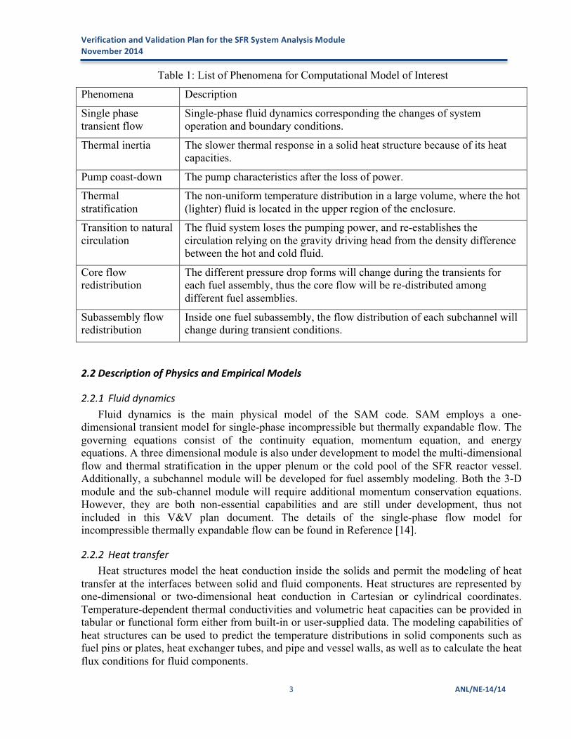
Table 1: List of Phenomena for Computational Model of Interest
Phenomena Description
Single phase transient flow
Single-phase fluid dynamics corresponding the changes of system operation and boundary conditions.
Thermal inertia The slower thermal response in a solid heat structure because of its heat capacities.
Pump coast-down The pump characteristics after the loss of power.
Thermal stratification
The non-uniform temperature distribution in a large volume, where the hot (lighter) fluid is located in the upper region of the enclosure.
Transition to natural circulation
The fluid system loses the pumping power, and re-establishes the circulation relying on the gravity driving head from the density difference between the hot and cold fluid.
Core flow redistribution
The different pressure drop forms will change during the transients for each fuel assembly, thus the core flow will be re-distributed among different fuel assemblies.
Subassembly flow redistribution
Inside one fuel subassembly, the flow distribution of each subchannel will change during transient conditions.
2.2 Description of Physics and Empirical Models
2.2.1 Fluid dynamics Fluid dynamics is the main physical model of the SAM code. SAM employs a one-
dimensional transient model for single-phase incompressible but thermally expandable flow. The governing equations consist of the continuity equation, momentum equation, and energy equations. A three dimensional module is also under development to model the multi-dimensional flow and thermal stratification in the upper plenum or the cold pool of the SFR reactor vessel. Additionally, a subchannel module will be developed for fuel assembly modeling. Both the 3-D module and the sub-channel module will require additional momentum conservation equations. However, they are both non-essential capabilities and are still under development, thus not included in this V&V plan document. The details of the single-phase flow model for incompressible thermally expandable flow can be found in Reference [14].
2.2.2 Heat transfer Heat structures model the heat conduction inside the solids and permit the modeling of heat
transfer at the interfaces between solid and fluid components. Heat structures are represented by one-dimensional or two-dimensional heat conduction in Cartesian or cylindrical coordinates. Temperature-dependent thermal conductivities and volumetric heat capacities can be provided in tabular or functional form either from built-in or user-supplied data. The modeling capabilities of heat structures can be used to predict the temperature distributions in solid components such as fuel pins or plates, heat exchanger tubes, and pipe and vessel walls, as well as to calculate the heat flux conditions for fluid components.

Verification and Validation Plan for the SFR System Analysis Module November 2014
ANL/NE-‐14/14 4
2.2.3 Sodium property model and constitutive models The sodium property model in SAS4A/SASSYS-1 [15] is implemented in SAM. In this
model, most sodium properties are dependent on temperature only. These include heat capacity, thermal conductivity, viscosity, compressibility, and thermal expansion coefficient, etc. A sodium equation of state (EOS) model is required to complete the flow governing equations, which is based on the primitive variable formulation; therefore, the dependency of sodium properties and their partial derivatives on the state variables (pressure and temperature) are implemented in the EOS model.
Empirical correlations for friction factor and convective heat transfer coefficient are required in SAM because of its one-dimension approximation of the flow field. The friction and heat transfer coefficients are dependent on flow conditions during the transient. The McAdams and Blasius correlations [16] are the default models for the turbulent wall friction factor, and the Seban and Shimazaki correlation [16] is the default model for the liquid metal heat transfer coefficient. These correlations were the same as those implemented in SAS4A/SASSYS-1. Additional friction and heat transfer correlations are available or will be added in the code and can be defined by user input for different applications. It should be noted that the accurate modeling of many phenomena listed in Table 1 will require accurate modeling of the friction and form pressure losses in SFR components during steady and transient conditions.
2.2.4 Component models The physics modeling (fluid flow and heat transfer) and mesh generation of individual reactor
components are encapsulated as Component classes in SAM along with some component specific models. A set of components has been developed based on the FEM fluid model and heat conduction model, including: (1) 1-D geometric components such as pipe, core channel, heat exchanger; (2) 0-D components such as time dependent volume and time dependent junction for setting boundary conditions; and (3) 0-D components such as junctions, branches, and pumps for connecting 1-D components.
2.3 Required Toolkit Elements and Libraries SAM is built on the computational framework MOOSE (Multi-physics Object-Oriented
Simulation Environment) to interface with LibMesh and PETSc to provide the underlying geometry (mesh I/O) and numerical capabilities (finite element library and solvers). It requires all of the code dependencies as MOOSE requires. A summary of the dependent libraries for the SFR System Analysis Module is listed in Table 2.

Verification and Validation Plan for the SFR System Analysis Module November 2014
5 ANL/NE-‐14/14
Table 2: Software Libraries Used by SAM
Library Origin Purpose
MOOSE [7] Idaho National Laboratory Computational framework, interfaces other libraries
LibMesh [8] University of Texas, Austin Finite element library
PETSc [9] Argonne National Laboratory Parallel linear and nonlinear solvers
Hypre (optional) [17] Lawrence Livermore National Laboratory
High performance preconditioners
MPICH [18] Argonne National Laboratory Message passing/parallel processing
TBB (optional) [19] Intel Corporation Multi-thread parallelism
All of these libraries must be downloaded and compiled in order to run the SFR System Analysis Module. To make this easier, the MOOSE team maintains a compiled set of all dependencies, except MOOSE and LibMesh, on the public MOOSE website (http://mooseframework.org/) with precompiled packages containing Petsc, Hypre, MPICH, and TBB for several Mac OS and Linux systems. MOOSE and LibMesh are available from the MOOSE GitHub site (https://github.com/idaholab/moose.git). For advanced users, all the dependent libraries are open-source codes and can thus be downloaded and compiled on Mac OS and Linux systems.
2.4 Consequence of Failure, Quality Rigor Level, Risk Grading SAM simulations are used to gain basic understandings of system responses and to examine
the safety margins during reactor transients. User expertise in system modeling of nuclear rectors, the applicability of lumped parameter models, the knowledge of the specific reactor design and the phenomena present in particular transients are required for an accurate simulation of reactor transients. Additionally, lack of appropriate physics models (coupled neutron kinetics and structural feedback) can degrade the quality of the system thermal-hydraulics solutions.
SAM is currently a Quality Rigor Level 3 (QRL) code, which is a “research and development activity that is exploratory, preliminary, or investigative in nature”[5]. As a QRL 3 code, SAM must meet verification requirements including regular regression testing, error tracking, and configuration management with documentation. It must also perform unit test validation and sensitivity studies. SAM currently meets these standards, however, the goal is to build up the V&V of SAM such that it meets the more rigorous QRL 2 requirements.
The consequences of failure are poor prediction of the physics phenomena, including overestimation or underestimation of the safety margins to structural failure. Additionally, in a coupled multi-scale multi-physics scenario, inaccurate solution transfer would affect the other physics modules. However, since QRL 3 codes are understood to be exploratory in nature, any conclusions drawn from SAM in its current state shall stay within QRL 3 expectations and not used in a QRL 2 manner to inform important decisions. Again, the goal is to transition SAM to a QRL 2 code whereby it will be much better verified, validated, and documented.

Verification and Validation Plan for the SFR System Analysis Module November 2014
ANL/NE-‐14/14 6
2.5 Hardware and Software Platforms SAM, due to its dependence on MOOSE, is not compatible with Windows operating systems.
However it is fully compatible with Linux, Unix, and MacOS. It is a flexible code that can be used for small problems that can be run on a desktop or laptop, as well as large problems that require a small-size cluster. Typically, small problems with less than 5,000 dofs (degrees of freedom) can be run on a laptop computer. Medium to large problems (5,000 – 10,000 dofs) can be run on a powerful desktop. Larger problems typically require a small cluster. However, it is unlikely that the reactor system analyses using SAM will require more than 100 processors.
3 Model Verification and Validation
3.1 Software Verification Software verification is the process of ensuring that the software satisfies the expected
requirements and was built according to expectation. It answers the question of whether the software is solving the problem as intended by the programmer. Software verification is important in order to eliminate mistakes or bugs in the code as a source of error. This section describes the software verification of SAM.
3.1.1 Software Version Control SAM is hosted in a private, access-controlled Subversion (SVN) repository at Argonne
National Laboratory. All changes to the source code are committed with revision number, comments, and tracked in the repository. Since the code is still under the initial stage of the development, the naming procedure (i.e. Version 1.0, with date and corresponding documentation) will be established upon its initial distribution.
3.1.2 Regression, Benchmark Tests, and Bug Reporting The code is updated actively to add new features. In order to ensure the code is working
properly after (a) installation on a new architecture, and (b) modifications to the source code, a series of regression tests and benchmark tests shall be performed. SAM employs the rigorous quality assurance structure. For each capability within SAM, a test problem has been checked into the repository along with a “gold” result file that represents the reference result. Currently, there are more than 100 tests for SAM. Any time a change is made to SAM, all the tests are executed; if any of the results from these tests do not match the “gold” file, the problem will be identified and repaired.
The current regression test suite includes: (1) basic physics model (fluid flow, heat transfer, equation-of-state, etc.) tests; (2) component tests; (3) additional verification tests with analytical solutions; (4) tests for code structures or special code features; and (5) larger demonstration problems such as ABTR[20] and EBR-IIError! Reference source not found. tests.
Problems or bugs shall be reported directly to developers. A ticket in the TRAC system shall be created to describe the bug. After resolution of the problem, the ticketing system shall be

Verification and Validation Plan for the SFR System Analysis Module November 2014
7 ANL/NE-‐14/14
updated to describe the solution, refer to the SVN revision number containing the fix, and close the ticket. Once the code is distributed, this procedure will be strictly enforced.
3.1.3 Documentation A user manual and a theory manual for SAM are still lacking, but will be needed with the
distribution. The theory manual will describe the physics models being solved, the discretization scheme, and the solution methods. The user manual will describe how to obtain, install, and simulate problems using SAM. Sample test problems, input file format descriptions, and training materials will be available for distribution as well.
Additionally, V&V test documentation is needed following the execution of this V&V plan. Following the IEEE Std 829-1998[1], this includes test plan, test case specification, test procedure specification, test item transmittal report, test log, test incident report, and test summary report.
3.1.4 Static Analysis Static analysis is the process of checking that software meets requirements by doing a
physical inspection. Static analysis is not currently performed, as the dynamic analysis (regression and benchmark tests) fully cover the required testing. However, static analysis could be implemented easily if there was a need.
3.1.5 Verification with Analytical Benchmarks A set of analytical benchmark problems (some are documented in Ref. [14][22]) has been
developed to test the basic fluid flow and heat conduction models and some basic reactor components. These benchmarks typically contain simple geometries and/or conditions such that it is possible to obtain analytic solutions. The wide range of analytical benchmarks provides confidence that the physical models are correctly implemented and the numerical algorithms are representing the physics correctly. Additional verification test will be developed as new capabilities are added to the code and the QRL is upgraded. Furthermore, the method of manufactured solutions (MMS) can be used to generate analytic solutions to additional test problems.
3.1.6 Verification with Code-‐to-‐Code Comparison Due to the limited availability of experimental data for actual SFRs or sodium system
operations, SAM is also verified against other more established codes or reference solutions. SAS4A/SASYS-1 is typically used for SFR safety analysis and licensing support. Specific problems can be devised to test the physics of interest. For examples, the models for ABTR and EBR-II have been developed to compare against the SAS4A/SASSYS-1 solution to assess the general transient trends and the differences between the two codes. Formal benchmarks Error! Reference source not found. contain numerous code results and reference solutions, which can be compared against for code verification.

Verification and Validation Plan for the SFR System Analysis Module November 2014
ANL/NE-‐14/14 8
3.2 Software Validation Software validation is the process of evaluating a code during or at the end of the
development process to determine whether it satisfies specified requirements. This section describes how software validation of SAM is carried out.
3.2.1 Unit, Component, Subsystem, System, Integral tests A hierarchy of tests, known as unit, component, subsystem, system, and integral tests, shall be
performed to comprehensively validate the SAM code. Unit tests are typically associated with tests for individual functions, classes, or modules of the code. A comprehensive set of unit tests helps ensure complete code line coverage, which is very valuable for software quality assurance control. A component test typically contains single physics effects or consists of single reactor component types. A subsystem or system test typically contains multiple physical phenomena and multiple reactor system components, but is still a subset of the full physics domain. Examples for system thermal-hydraulics analyses include a reactor core with multiple core channels or an intermediate heat transport system. An integral test typically models the entire system of a nuclear reactor, including the reactor core, primary and intermediate heat transport system, decay heat removal systems, and the balance-of-plant.
3.2.2 Validation Matrix and Gaps The hierarchy of the validation tests described in section 3.2.1 is similar to the hierarchy of
experiments in a validation matrix proposed in the V&V strategy developed in the DOE LWRS program, as shown in Figure 1 [23]. The required number of tests would decrease as the hierarchy moves from the unit/basic/separate effect tests up to integral effects tests and plant operation data.
Figure 1: Hierarchy of Experiments in a Validation Matrix
Verification and Validation Plan for the SFR System Analysis Module November 2014
9 ANL/NE-‐14/14
The development of qualified data to be used in the V&V process is as important as the code development and validation effort itself. A critical assessment of the pedigree of legacy data needs to be key part of the V&V activities. The data shall be scrutinized and its applicability, uncertainty, and quality established early in the V&V effort. This will then support what new experiments need to be performed. This effort shall leverage the DOE Advanced Reactor Technology Fast Reactor Program’s (ART-FR) Fast Reactor Knowledge Preservation Task [24] in which the EBR-II, FFTF, and TREAT data are being collected and organized in respective databases.
Based on the phenomena that need to be validated, a matrix of separate, mixed, and integral effects experiments spanning the anticipated length and time scales will be developed in accordance with NRC RG1.203 [25]. Table 3 is an example validation matrix describing which tests can be used to validate, or partially validate, the desired phenomena from Table 1. Please note the experimental facilities and reactors listed in Table 3 are yet to be identified. Furthermore, some tests listed in the table will be reserved as standard tests for model development; additional tests may be needed for code validation once the SAM code is more mature and distributed for use. Special attention will be focused on the code validation using the EBRI-II Shutdown Heat Removal Tests and FFTF Inherent Safety Test Series data because: 1) DOE owns the data; 2) data are being retrieved by the ART-FR program; 3) the tests are critical to demonstrate the inherent safety of the SFR design, and 4) the tests are among the most challenging problems in the modeling and simulations of SFRs. It should be noted that the EBR-II and FFTF tests are also of significant interests of the Proteus V&V plan [26].
EBRI-II Shutdown Heat Removal Tests
Argonne National Laboratory’s Experimental Breeder Reactor II (EBR-II) Error! Reference source not found. was a liquid metal reactor with a sodium-bonded metallic fuel core. The SHRT-17 test in 1984 demonstrated the effectiveness of natural circulation in EBR-II under severe loss-of-flow test conditions. The follow-up SHRT-45R test performed in 1986 was similar to SHRT-17 except the plant protection system (PPS) was disabled to prevent it from initiating a control rod scram. Both SHRT-17 and SHRT-45R were initiated by tripping the primary coolant pumps and the intermediate loop pump to simulate a loss-of-flow accident. In SHRT-45R, the loss of forced coolant flow caused the reactor temperature to rise temporarily but eventually shut down due to negative reactivity feedback from thermal expansion. A variety of temperature and flow data exists for these tests, but the measurement data is likely to have large uncertainties.
FFTF Inherent Safety Test Series
A series of tests was performed at the 400-MWth Fast Flux Test Facility (FFTF) [27] to demonstrate the passive safety characteristics of liquid-metal-cooled fast reactors. In 1981, FFTF tests were performed to measure decay heat removal by sodium natural circulation. The 1986 test series demonstrated passive reactor shutdown during a loss-of-flow event when several inherent shutdown devices called gas expansion modules (GEMs) were installed in the reactor. These tests also provided additional data on the natural circulation performance of the primary system, in particular the reactor core, and thus add to the database available for checking the validity of available analytical tools.

Verification and Validation Plan for the SFR System Analysis Module November 2014
ANL/NE-‐14/14 10
Table 3: Validation Matrix for SAM
TEST MATRIX FOR CODE VALIDATIONFacility 1 Facility 2 Facility 3 Facility 4 Facility 5 Facility 6 Facility 7 Facility 8 Facility 9 Facility 10 Facility 11 Facility 12 EBR-II FFTF SFR-3
Number of problems n n n n n n n n n n n n n n nBASIC PHENOMENOLOGICAL MODELSK-factor form losses X X X X X X X XWall surface roughness X X X X X X XWall drag friction X X X X X X XAbrupted-flow-area change form losses X X X X X X X XGravity-head term in motion equation X X X X X X X X X2D radial and axial conduction X X X XFluid conduction X X X X XConvection heat transfer X X X X X X X XFuel (fuel/gap/clad) models X X X X X XConstant power source X X XAdiabatic inner surface X X X XMaterials prroperties data X X X XParallel channel flow X X X XPlenum coupling X X X X X X XMultiple connections X X X X X X XWall heat transfer for 0-D components X X XHeat generation in 0-D components X XReactivity-feedback X XWire spacer friction X X X X XMomentum convection X X X XSubchannel mixing X XPowered and unpowered heat structures X XBOUNDARY CONDITIONSNo flow BC X X XInlet velocity function/table BC X X X X XMass flow function/table BC X XConstant atm pressure BC X X X X XInlet/Outlet pressure function/table BCInlet temperature function/table BC XConstant power X X XPower vs time X X X XSteady-state asymptotic calculation X X XScramed power vs time X X XTYPES OF CALCULATIONSSingle-phase flow trainsient X X X X X X X X X XTransient heatup/cooldown X X X X X X XPump coast-down X X X XThermal stratification X X X XTransition to natural circulation X X X X XCore flow redistribution X X X X XSubassembly flow redistribution XNumerical convergence X XRestart calculation X XCalculation reproducibility X XAll control signal paramaters X XCOMPONENTS USEDOneDFluidComponent X X X X X X X X X X X X X X XCoupledHeatStructure X XPipe X X X X X X XHeatExchanger X X XCoreChannel X X X X XDuctedCoreChannel X xBypassChannel X XFuelAssembly X X XDuctedFuelAssembly X XReactorCore XBranch X X X X X X X X X XSingleJunction X X X X X X X X XPump X X X X X X X X XVolumeBranch X X X X X X X XCoverGas X X XLiquidVolume X X X X XTDJ X X X X X X X X X X X X X X XTDV X X X X X X X X X X X X X XCoupledTDV X

Verification and Validation Plan for the SFR System Analysis Module November 2014
11 ANL/NE-‐14/14
3.2.3 Schedule and Priorities This report only identifies limited relevant SFR experiments, and other test facilities and
reactor experiments will be needed for a comprehensive code validation. One important following task will consist of the identification of available experiments and developing two separate but comprehensive validation test matrices: one for code development and the other for code validation. The priority of the code validation will be given to tests for which the development team has convenient access to the experimental data and to the international benchmarks that contain numerous code entries and reference solutions for comparisons.
The validation of SAM for each experiment is an extensive task and consists of the following steps: (1) collection of experiment specification and measurement data, (2) developing the basic test model, (3) initial testing of model and optimization of model parameters, and (4) documenting the validation results. The gathering of actual experimental specifications and measurements may be lengthy since it is not necessarily within the control of the development team.
4 Sensitivity Analysis and Uncertainty Quantification The system safety analysis of SFR involves many uncertainties associated with geometric and
modeling parameters, material properties, and modeling assumptions. In order to assess the effects of the uncertainties and determine the safety margins for a specific reactor design, uncertainty quantification (UQ) and sensitivity analysis are required. Therefor, some level of UQ shall be incorporated into the validation studies.
Sensitivity analyses are important to explore the sources of variability in computational results. The propagation of uncertainties in input or modeling parameters though the SAM code will benefit from the use of specialized UQ tools such as DAKOTA[28] and RAVEN[29] in which the calculation uncertainties can be evaluated from the statistical distribution of parameter uncertainties. For code validation, the experimental uncertainty, which is composed of the uncertainties of measurement, material, and geometry, i.e., due to the inherent experimental uncertainty in measurements, and due to the manufacturing tolerances for any given structural component, needs to be known. This is likely to be best characterized for smaller, more focused experiments. The experimental uncertainties shall be provided by the owners of the experiment data.
5 Path Forward SAM is an advanced system analysis tool for SFR whole-plant transient analysis. It is being
developed as an important piece of the NEAMS Reactor Product Line toolkit. In order to establish confidence in predictions and to quantify the uncertainty in SAM calculations, a significant V&V effort is needed. Most of the basic models in SAM have been verified against analytical models, though more verification is needed.
An important step in validation is to develop more comprehensive validation matrices for both code development and code validation. Validation matrices can be refined in the future as more experimental data are available. Rigorous validation activities will be performed against the

Verification and Validation Plan for the SFR System Analysis Module November 2014
ANL/NE-‐14/14 12
experiment listed in the validation matrices. Code validation shall begin with the EBR-II SHRT17 and SHRT45 tests since there is an ongoing IAEA Coordinated Research Project (CRP) on “Benchmark Analyses of EBR-II Shutdown Heat Removal Tests” in which the results from all participants will be presented, compared, and documented.
REFERENCES
[1] R. Hu and T. H. Fanning, “NEAMS SFR System Module: Overview and Development Status,” Proceedings of ICAPP 2014, Charlotte, USA, April 6-9, 2014.
[2] R. Hu and T.H. Fanning, “Update on Developments for the SFR System Analysis Module,” ANL/NE-14/9, Argonne National Laboratory, September 2014.
[3] IEEE Std 829-1998, “IEEE Standard for Software Test Documentation”, 1998. [4] IEEE Std 1012-2004, “IEEE Standard for Software Verification and Validation,” 2004. [5] R. M. Versluis, “NEAMS Software Verification and Validation Plan Requirements,
Version 0,” Department of Energy, Office of Advanced Modeling and Simulation, 2013. [6] R. Versluis, Personal communication, April 2014. [7] D. Gaston, C. Newman, G. Hansen, and D. Lebrun-Grandi´e, “MOOSE: A parallel
computational framework for coupled systems of nonlinear equations,” Nuclear Engineering and Design, vol. 239, pp. 1768–1778, 2009.
[8] B. S. Kirk, J. W. Peterson, R. H. Stogner, and G. F. Carey, “libMesh: A C++ Library for Parallel Adaptive Mesh Refinement/Coarsening Simulations,” Engineering with Computers, 22(3-4): 237-254, 2006.
[9] S. Balay, J. Brown, et al, PETSc Web page, http://www.mcs.anl.gov/petsc, 2014. [10] P. F. Fischer, J. W. Lottes, S. G. Kerkemier, Nek5000 Web Page,
http://nek5000.mcs.anl.gov, 2014. [11] E. R. Shemon, C. H. Lee, M. A. Smith, and A. Marin-Lafleche, “NEAMS Neutronics:
Development and Validation Status,” Proceedings of ICAPP 2014, Charlotte, USA, April 6-9, 2014.
[12] D. Parsons, et al, “Diablo User Manual,” Lawrence Livermore National Laboratory Report UCRL-SM-234927, Sept 2007.
[13] R. Schmidt, T. Sofu, T. Wei, et al., “Sodium Fast Reactor Gaps Analysis of Computer Codes and Models for Accident Analysis and Reactor Safety,” SAND2011-4145, Sandia National Laboratory, June 2011.
[14] R. Hu, "A Fully-Coupled Finite Element Formulation for One-Dimensional Incompressible Thermally Expandable Flow," Proceedings of ATH'14, Reno, NV, June 15-19, 2014.
[15] T. H. Fanning, ed., The SAS4A/SASSYS-1 Safety Analysis Code System, Argonne National Laboratory, ANL/NE-12/4, January 31, 2012.
[16] N.E. Todreas and M.S. Kazimi, “Nuclear Systems I – Thermal Hydraulic Fundamentals,” Hemisphere Publishing Corporation, 1990.

Verification and Validation Plan for the SFR System Analysis Module November 2014
13 ANL/NE-‐14/14
[17] Hypre Website, https://computation-rnd.llnl.gov/linear_solvers/ [18] MPICH2 Website, http://www.mcs.anl.gov/mpich2 [19] TBB Website, https://www.threadingbuildingblocks.org/ [20] Y. I. Chang, P. J. Finck, C. Grandy, et al., “Advanced Burner Test Reactor Preconceptual
Design Report,” ANL-ABR-1 (ANL-AFCI-173), Argonne National Laboratory, September 2006.
[21] T. Sofu and L. L. Briggs, "Benchmark Specifications for EBR-II Shutdown Heat Removal Tests", Proceedings of the 2012 International Congress on Advances in Nuclear Power Plants - ICAPP '12, pp. 774-778, Chicago IL, June 2012.
[22] T. Sumner, R. Hu, T.H. Fanning, “Verification Test Suite for Systems Analysis Tools,” ANL/NE-12/61, Argonne National Laboratory, December 2012.
[23] C. Stoots, T. Larson, R. Schultz, et al., “Verification and Validation Strategy for LWRS Tools,” INL/EXT-12-27066, Idaho National Laboratory, September 2012.
[24] C. Grandy, “Fast Reactor Knowledge Preservation Efforts,” Presentation at the IAEA Fast Reactor Knowledge Preservation Meeting, Vienna, Austria, December 3-5, 2013.
[25] U.S. Nuclear Regulatory Commission, “Regulatory Guideline 1.203, Transient and Accident Analysis Methods,” December 2005.
[26] E.R. Shemon, C.H. Lee, and M.A. Smith, “Verification and Validation Plan for PROTEUS,” ANL/NE-14/8, Argonne National Laboratory, August 2014.
[27] T. M. Burke, et al, “Results of the 1986 FFTF Inherent Safety Tests,” Trans. Am. Nucl. Soc., 54, p 249-250, 1987.
[28] B. M. Adams, W. J. Bohnhoff, K. R. Dalbey, et al., “DAKOTA, A Multilevel Parallel Object-Oriented Framework for Design Optimization, Parameter Estimation, Uncertainty Quantification, and Sensitivity Analysis, Version 5.2 User's Manual,” SAND2011-9106, Sandia National Laboratories, December 2011.
[29] A. Alfonsi, C. Rabiti, D. Mandelli, et al., “RAVEN As a Tool for Dynamic Probabilistic Risk Assessment: Software Overview,” Proceedings of M&C 2013, May 2013.

Argonne National Laboratory is a U.S. Department of Energy laboratory managed by UChicago Argonne, LLC
Nuclear Engineering Division Argonne National Laboratory 9700 South Cass Avenue, Bldg. 208 Argonne, IL 60439-4832 www.anl.gov