Embed Size (px)
Citation preview
Ver 1,12/09/2012 Kode :CCs 111,Sistem basis Data FASILKOM
Database System Concepts, 5th Ed.©Silberschatz, Korth and Sudarshan
See www.db-book.com for conditions on re-use
CHAPTER 6: ENTITY-RELATIONSHIP MODEL
Ver 1,12/09/2012 Kode :CCs 111,Sistem basis Data FASILKOM
Chapter 6: Entity-Relationship Model
• Design Process• Modeling• Constraints• E-R Diagram • Design Issues • Weak Entity Sets • Extended E-R Features• Design of the Bank Database• Reduction to Relation Schemas• Database Design• UML
Ver 1,12/09/2012 Kode :CCs 111,Sistem basis Data FASILKOM
Modeling• A database can be modeled as:
– a collection of entities,– relationship among entities.
• An entity is an object that exists and is distinguishable from other objects.– Example: specific person, company, event, plant
• Entities have attributes– Example: people have names and addresses
• An entity set is a set of entities of the same type that share the same properties.– Example: set of all persons, companies, trees, holidays
Ver 1,12/09/2012 Kode :CCs 111,Sistem basis Data FASILKOM
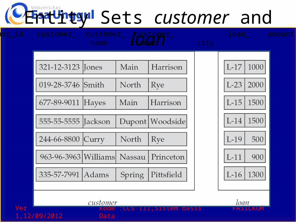
Entity Sets customer and loancustomer_id customer_ customer_ customer_ loan_ amount name street city number
Ver 1,12/09/2012 Kode :CCs 111,Sistem basis Data FASILKOM
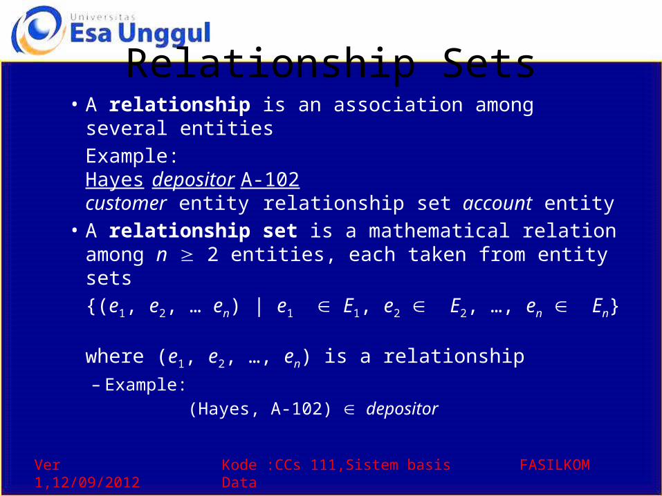
Relationship Sets• A relationship is an association among several entities
Example:Hayes depositor A-102customer entity relationship set account entity
• A relationship set is a mathematical relation among n 2 entities, each taken from entity sets{(e1, e2, … en) | e1 E1, e2 E2, …, en En}
where (e1, e2, …, en) is a relationship– Example:
(Hayes, A-102) depositor
Ver 1,12/09/2012 Kode :CCs 111,Sistem basis Data FASILKOM
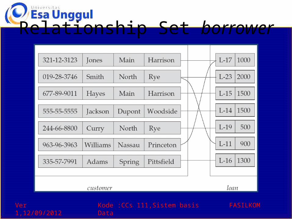
Relationship Set borrower
Ver 1,12/09/2012 Kode :CCs 111,Sistem basis Data FASILKOM
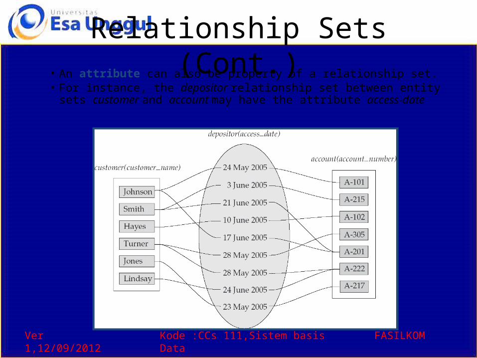
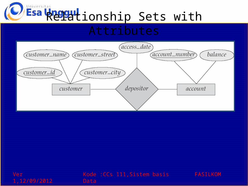
Relationship Sets (Cont.)• An attribute can also be property of a relationship set.• For instance, the depositor relationship set between entity
sets customer and account may have the attribute access-date

Ver 1,12/09/2012 Kode :CCs 111,Sistem basis Data FASILKOM
Degree of a Relationship Set• Refers to number of entity sets that participate in a
relationship set.• Relationship sets that involve two entity sets are binary (or
degree two). Generally, most relationship sets in a database system are binary.
• Relationship sets may involve more than two entity sets.
• Relationships between more than two entity sets are rare. Most relationships are binary. (More on this later.)
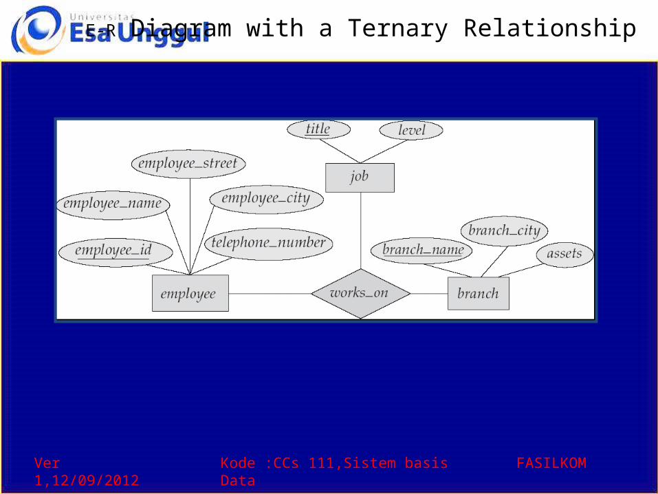
Example: Suppose employees of a bank may have jobs (responsibilities) at multiple branches, with different jobs at different branches. Then there is a ternary relationship set between entity sets employee, job, and branch
Ver 1,12/09/2012 Kode :CCs 111,Sistem basis Data FASILKOM
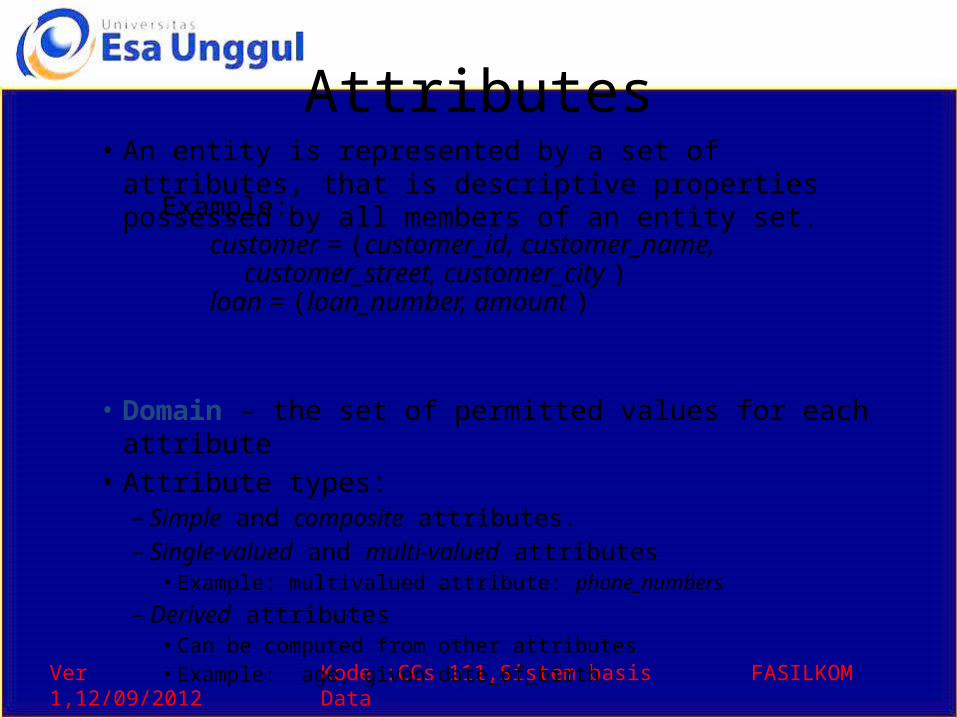
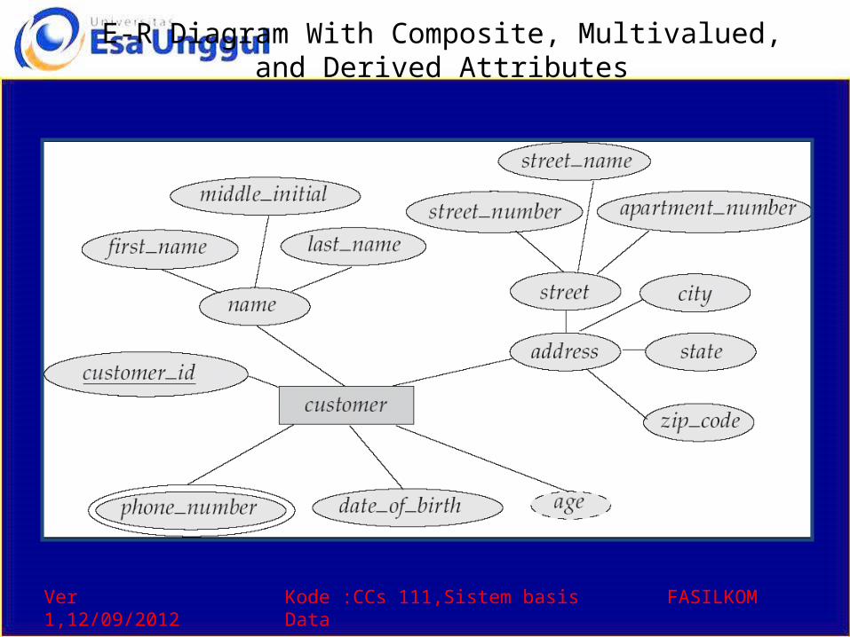
Attributes• An entity is represented by a set of attributes, that is
descriptive properties possessed by all members of an entity set.
• Domain – the set of permitted values for each attribute • Attribute types:
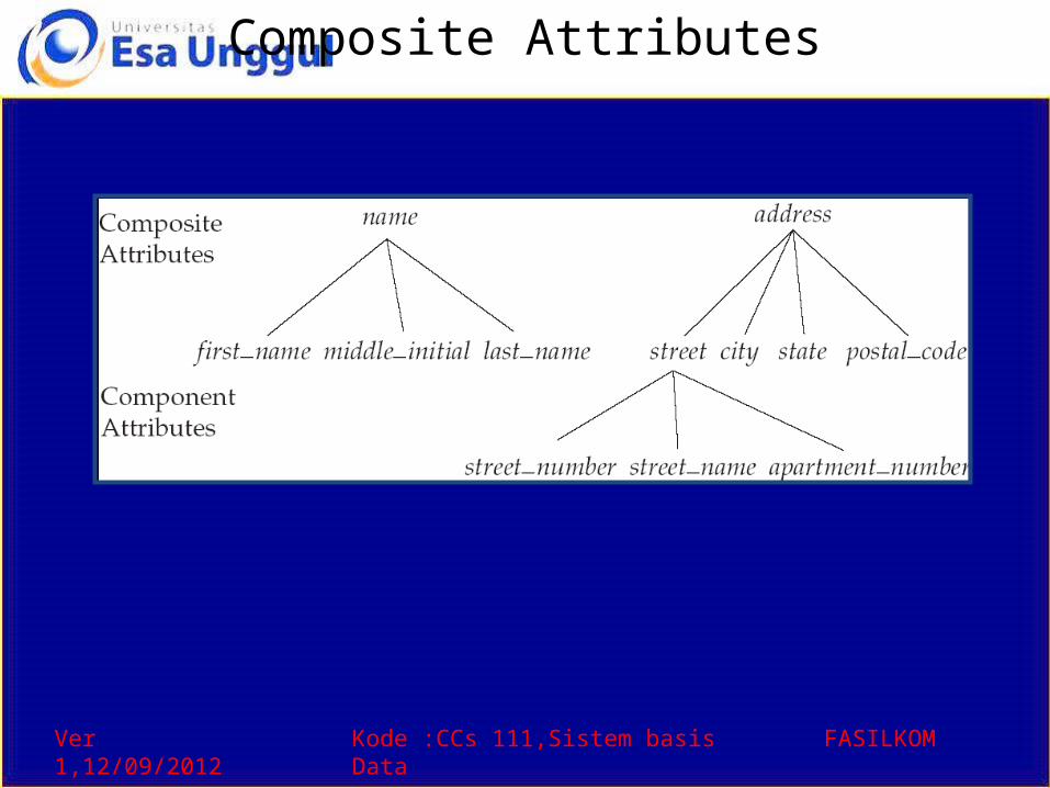
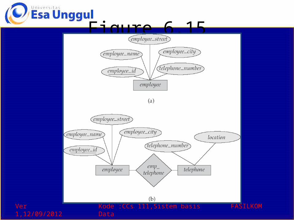
– Simple and composite attributes.– Single-valued and multi-valued attributes
• Example: multivalued attribute: phone_numbers– Derived attributes
• Can be computed from other attributes• Example: age, given date_of_birth
Example:
customer = (customer_id, customer_name, customer_street, customer_city )
loan = (loan_number, amount )
Ver 1,12/09/2012 Kode :CCs 111,Sistem basis Data FASILKOM
Composite Attributes
Ver 1,12/09/2012 Kode :CCs 111,Sistem basis Data FASILKOM
Mapping Cardinality Constraints• Express the number of entities to which another
entity can be associated via a relationship set.• Most useful in describing binary relationship sets.• For a binary relationship set the mapping
cardinality must be one of the following types:– One to one– One to many– Many to one– Many to many

Ver 1,12/09/2012 Kode :CCs 111,Sistem basis Data FASILKOM
Mapping Cardinalities
One to one One to many
Note: Some elements in A and B may not be mapped to any elements in the other set
Ver 1,12/09/2012 Kode :CCs 111,Sistem basis Data FASILKOM
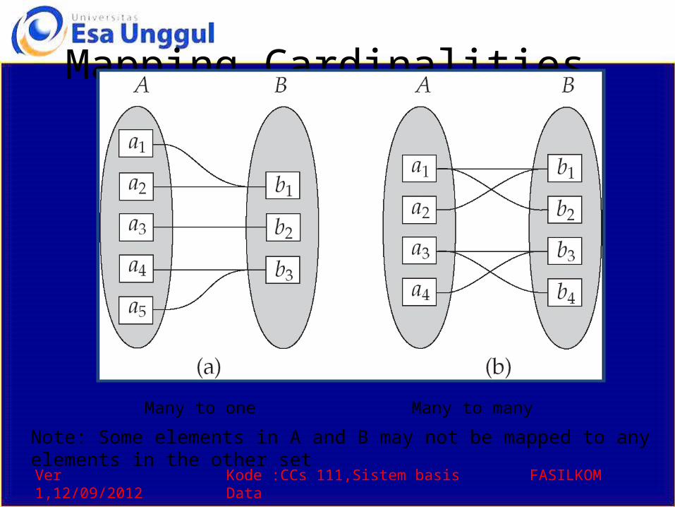
Mapping Cardinalities
Many to one Many to many
Note: Some elements in A and B may not be mapped to any elements in the other set
Ver 1,12/09/2012 Kode :CCs 111,Sistem basis Data FASILKOM
Keys• A super key of an entity set is a set of
one or more attributes whose values uniquely determine each entity.
• A candidate key of an entity set is a minimal super key– Customer_id is candidate key of customer– account_number is candidate key of account
• Although several candidate keys may exist, one of the candidate keys is selected to be the primary key.
Ver 1,12/09/2012 Kode :CCs 111,Sistem basis Data FASILKOM
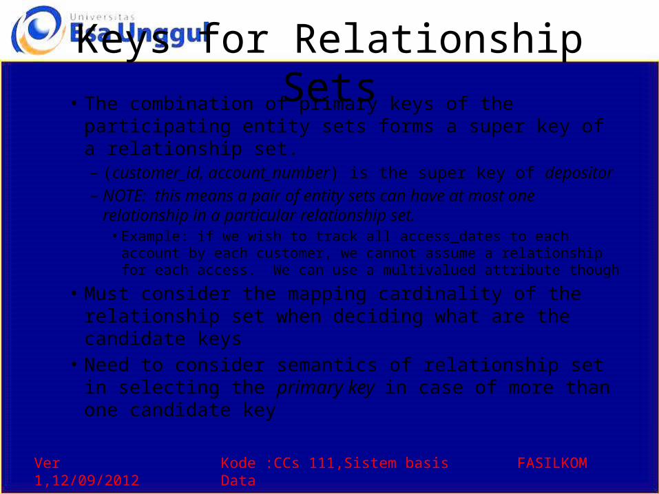
Keys for Relationship Sets• The combination of primary keys of the participating
entity sets forms a super key of a relationship set.– (customer_id, account_number) is the super key of depositor– NOTE: this means a pair of entity sets can have at most one
relationship in a particular relationship set. • Example: if we wish to track all access_dates to each account by each
customer, we cannot assume a relationship for each access. We can use a multivalued attribute though
• Must consider the mapping cardinality of the relationship set when deciding what are the candidate keys
• Need to consider semantics of relationship set in selecting the primary key in case of more than one candidate key
Ver 1,12/09/2012 Kode :CCs 111,Sistem basis Data FASILKOM
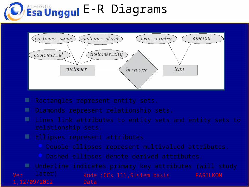
E-R Diagrams
Rectangles represent entity sets. Diamonds represent relationship sets. Lines link attributes to entity sets and entity sets to relationship sets. Ellipses represent attributes
Double ellipses represent multivalued attributes. Dashed ellipses denote derived attributes.
Underline indicates primary key attributes (will study later)
Ver 1,12/09/2012 Kode :CCs 111,Sistem basis Data FASILKOM
E-R Diagram With Composite, Multivalued, and Derived Attributes
Ver 1,12/09/2012 Kode :CCs 111,Sistem basis Data FASILKOM
Relationship Sets with Attributes
Ver 1,12/09/2012 Kode :CCs 111,Sistem basis Data FASILKOM
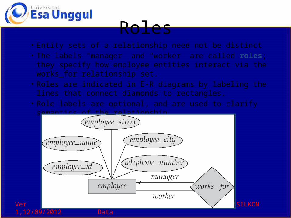
Roles• Entity sets of a relationship need not be distinct• The labels “manager” and “worker” are called roles; they specify
how employee entities interact via the works_for relationship set.• Roles are indicated in E-R diagrams by labeling the lines that
connect diamonds to rectangles.• Role labels are optional, and are used to clarify semantics of the
relationship
Ver 1,12/09/2012 Kode :CCs 111,Sistem basis Data FASILKOM
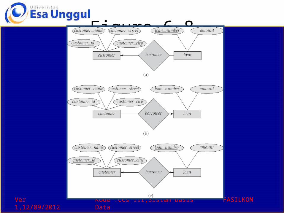
Cardinality Constraints• We express cardinality constraints by drawing either a directed
line (), signifying “one,” or an undirected line (—), signifying “many,” between the relationship set and the entity set.
• One-to-one relationship:– A customer is associated with at most one loan via the relationship
borrower– A loan is associated with at most one customer via borrower
Ver 1,12/09/2012 Kode :CCs 111,Sistem basis Data FASILKOM
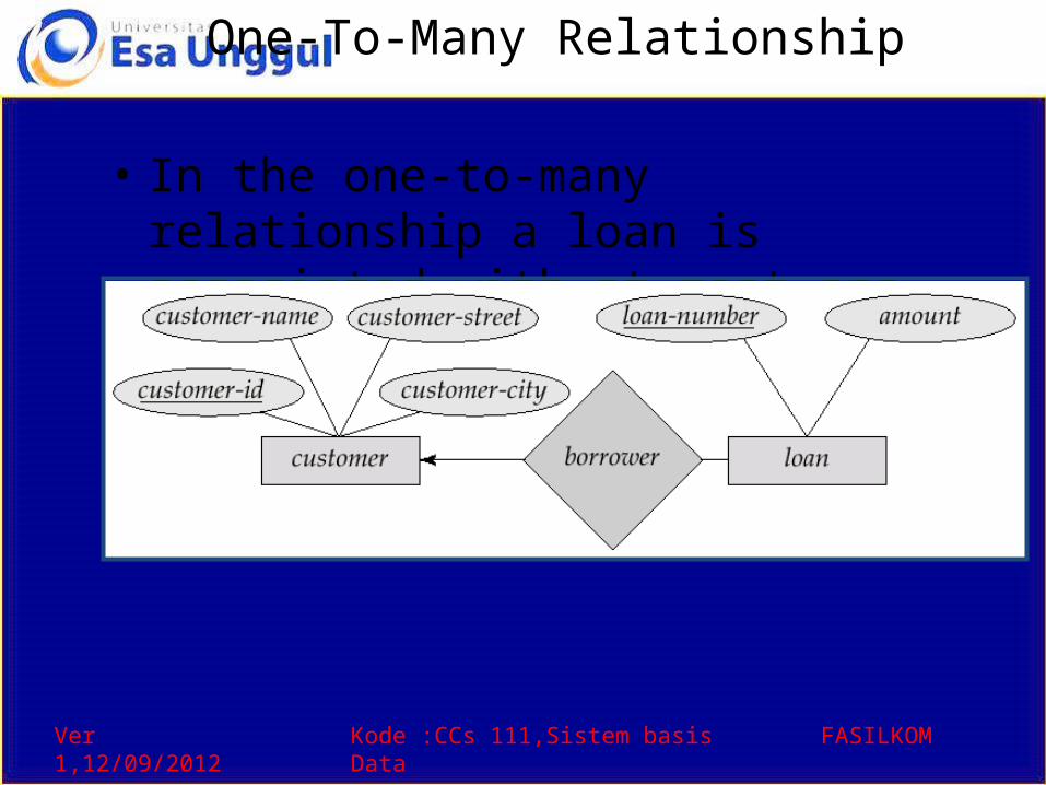
One-To-Many Relationship
• In the one-to-many relationship a loan is associated with at most one customer via borrower, a customer is associated with several (including 0) loans via borrower
Ver 1,12/09/2012 Kode :CCs 111,Sistem basis Data FASILKOM
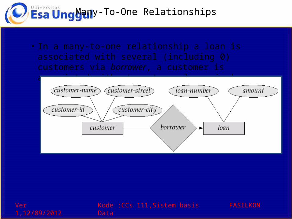
Many-To-One Relationships
• In a many-to-one relationship a loan is associated with several (including 0) customers via borrower, a customer is associated with at most one loan via borrower
Ver 1,12/09/2012 Kode :CCs 111,Sistem basis Data FASILKOM
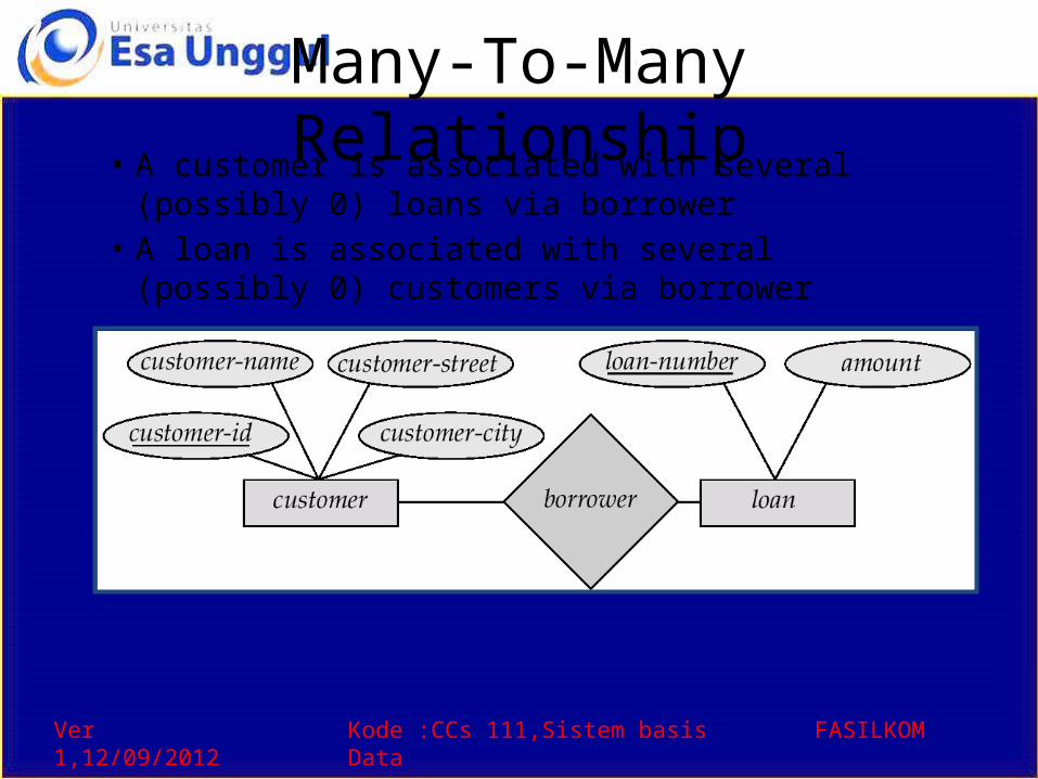
Many-To-Many Relationship• A customer is associated with several (possibly 0)
loans via borrower• A loan is associated with several (possibly 0)
customers via borrower
Ver 1,12/09/2012 Kode :CCs 111,Sistem basis Data FASILKOM
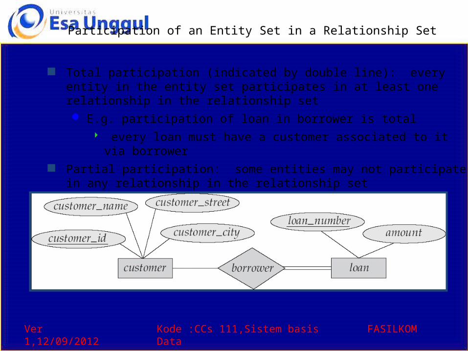
Participation of an Entity Set in a Relationship Set
Total participation (indicated by double line): every entity in the entity set participates in at least one relationship in the relationship set E.g. participation of loan in borrower is total
every loan must have a customer associated to it via borrower Partial participation: some entities may not participate in any relationship in
the relationship set Example: participation of customer in borrower is partial
Ver 1,12/09/2012 Kode :CCs 111,Sistem basis Data FASILKOM
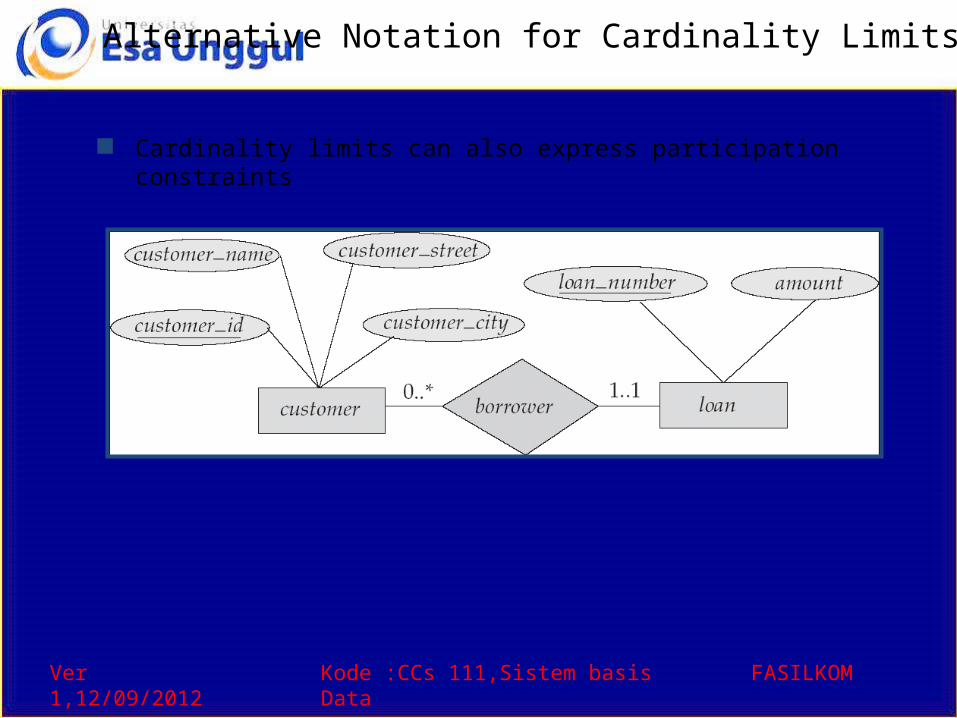
Alternative Notation for Cardinality Limits
Cardinality limits can also express participation constraints
Ver 1,12/09/2012 Kode :CCs 111,Sistem basis Data FASILKOM
E-R Diagram with a Ternary Relationship
Ver 1,12/09/2012 Kode :CCs 111,Sistem basis Data FASILKOM
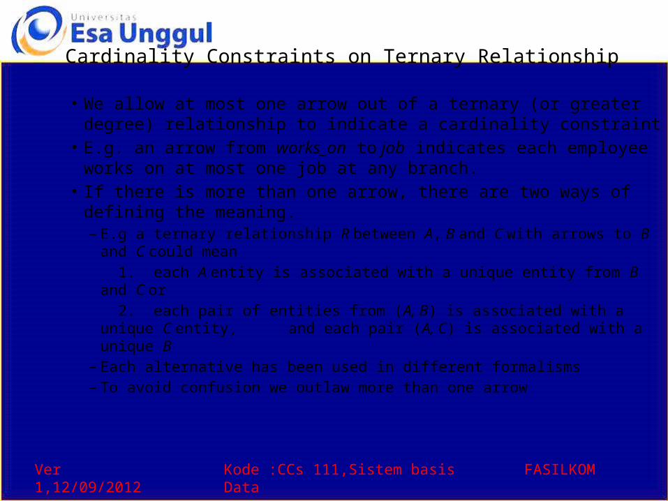
Cardinality Constraints on Ternary Relationship• We allow at most one arrow out of a ternary (or greater degree)
relationship to indicate a cardinality constraint• E.g. an arrow from works_on to job indicates each employee works
on at most one job at any branch.• If there is more than one arrow, there are two ways of defining the
meaning. – E.g a ternary relationship R between A, B and C with arrows to B and C
could mean 1. each A entity is associated with a unique entity from B and C or 2. each pair of entities from (A, B) is associated with a unique C entity, and each pair (A, C) is associated with a unique B
– Each alternative has been used in different formalisms– To avoid confusion we outlaw more than one arrow
Ver 1,12/09/2012 Kode :CCs 111,Sistem basis Data FASILKOM
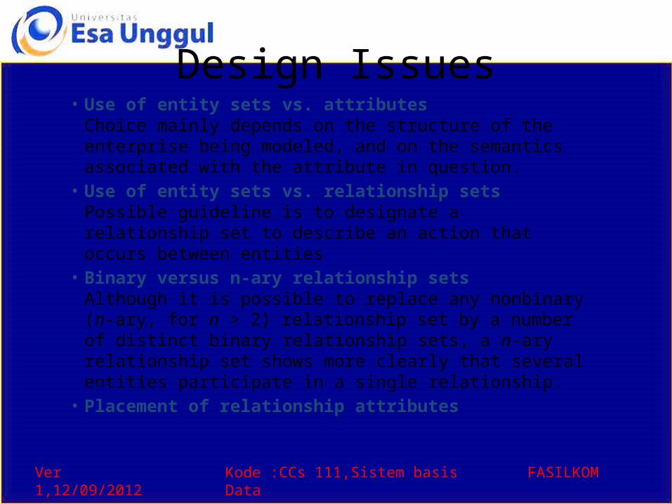
Design Issues• Use of entity sets vs. attributes
Choice mainly depends on the structure of the enterprise being modeled, and on the semantics associated with the attribute in question.
• Use of entity sets vs. relationship setsPossible guideline is to designate a relationship set to describe an action that occurs between entities
• Binary versus n-ary relationship setsAlthough it is possible to replace any nonbinary (n-ary, for n > 2) relationship set by a number of distinct binary relationship sets, a n-ary relationship set shows more clearly that several entities participate in a single relationship.
• Placement of relationship attributes
Ver 1,12/09/2012 Kode :CCs 111,Sistem basis Data FASILKOM
Binary Vs. Non-Binary Relationships
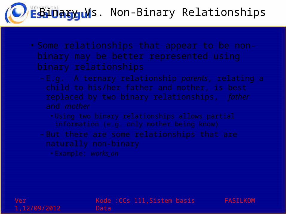
• Some relationships that appear to be non-binary may be better represented using binary relationships– E.g. A ternary relationship parents, relating a child to
his/her father and mother, is best replaced by two binary relationships, father and mother
• Using two binary relationships allows partial information (e.g. only mother being know)
– But there are some relationships that are naturally non-binary
• Example: works_on
Ver 1,12/09/2012 Kode :CCs 111,Sistem basis Data FASILKOM
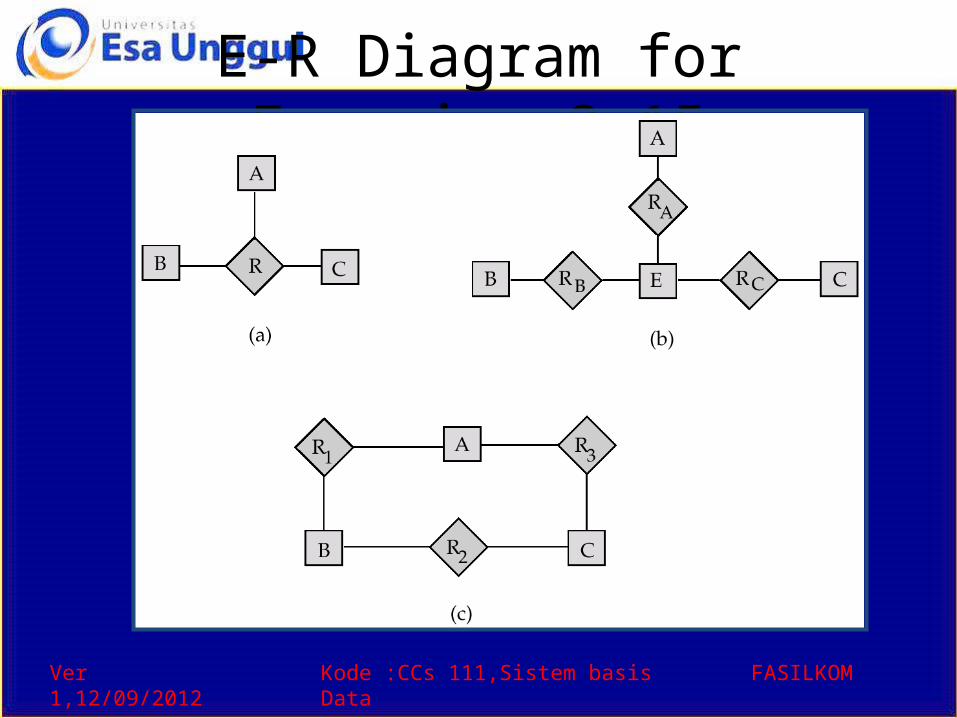
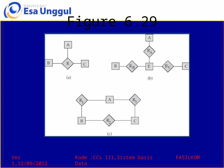
Converting Non-Binary Relationships to Binary Form
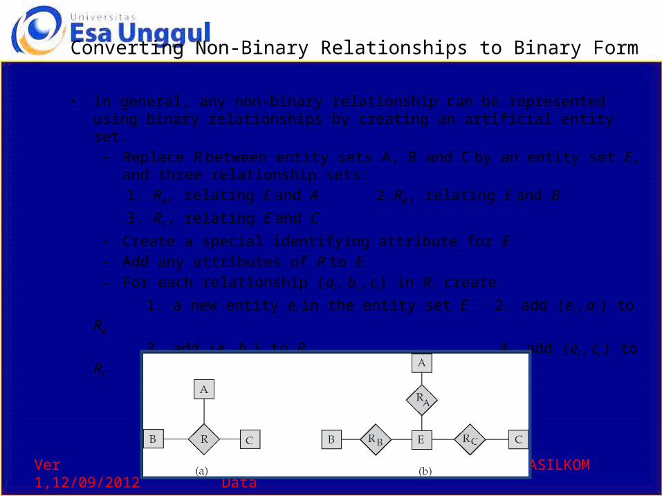
• In general, any non-binary relationship can be represented using binary relationships by creating an artificial entity set.
– Replace R between entity sets A, B and C by an entity set E, and three relationship sets: 1. RA, relating E and A 2.RB, relating E and B
3. RC, relating E and C– Create a special identifying attribute for E– Add any attributes of R to E – For each relationship (ai , bi , ci) in R, create
1. a new entity ei in the entity set E 2. add (ei , ai ) to RA
3. add (ei , bi ) to RB 4. add (ei , ci ) to RC
Ver 1,12/09/2012 Kode :CCs 111,Sistem basis Data FASILKOM
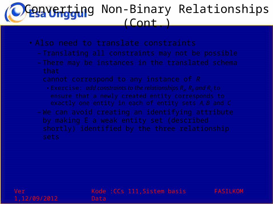
Converting Non-Binary Relationships (Cont.)
• Also need to translate constraints– Translating all constraints may not be possible– There may be instances in the translated schema that
cannot correspond to any instance of R• Exercise: add constraints to the relationships RA, RB and RC
to ensure that a newly created entity corresponds to exactly one entity in each of entity sets A, B and C
– We can avoid creating an identifying attribute by making E a weak entity set (described shortly) identified by the three relationship sets
Ver 1,12/09/2012 Kode :CCs 111,Sistem basis Data FASILKOM
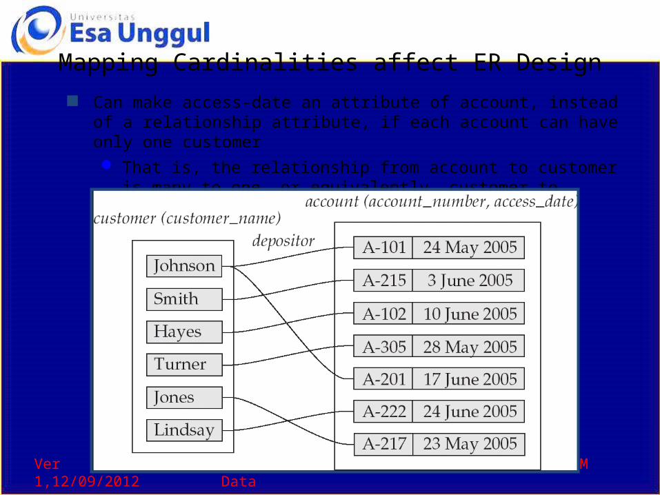
Mapping Cardinalities affect ER Design Can make access-date an attribute of account, instead of a relationship
attribute, if each account can have only one customer That is, the relationship from account to customer is many to one, or
equivalently, customer to account is one to many
Ver 1,12/09/2012 Kode :CCs 111,Sistem basis Data FASILKOM
How about doing an ER design interactively on the board?Suggest an application to be modeled.
Ver 1,12/09/2012 Kode :CCs 111,Sistem basis Data FASILKOM
Weak Entity Sets• An entity set that does not have a primary key is referred to
as a weak entity set.• The existence of a weak entity set depends on the existence
of a identifying entity set– it must relate to the identifying entity set via a total, one-to-many
relationship set from the identifying to the weak entity set– Identifying relationship depicted using a double diamond
• The discriminator (or partial key) of a weak entity set is the set of attributes that distinguishes among all the entities of a weak entity set.
• The primary key of a weak entity set is formed by the primary key of the strong entity set on which the weak entity set is existence dependent, plus the weak entity set’s discriminator.
Ver 1,12/09/2012 Kode :CCs 111,Sistem basis Data FASILKOM
Weak Entity Sets (Cont.)
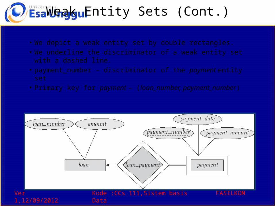
• We depict a weak entity set by double rectangles.• We underline the discriminator of a weak entity set with a
dashed line.• payment_number – discriminator of the payment entity set • Primary key for payment – (loan_number, payment_number)
Ver 1,12/09/2012 Kode :CCs 111,Sistem basis Data FASILKOM
Weak Entity Sets (Cont.)
• Note: the primary key of the strong entity set is not explicitly stored with the weak entity set, since it is implicit in the identifying relationship.
• If loan_number were explicitly stored, payment could be made a strong entity, but then the relationship between payment and loan would be duplicated by an implicit relationship defined by the attribute loan_number common to payment and loan
Ver 1,12/09/2012 Kode :CCs 111,Sistem basis Data FASILKOM
More Weak Entity Set Examples• In a university, a course is a strong entity and a
course_offering can be modeled as a weak entity• The discriminator of course_offering would be semester
(including year) and section_number (if there is more than one section)
• If we model course_offering as a strong entity we would model course_number as an attribute. Then the relationship with course would be implicit in the course_number attribute
Ver 1,12/09/2012 Kode :CCs 111,Sistem basis Data FASILKOM
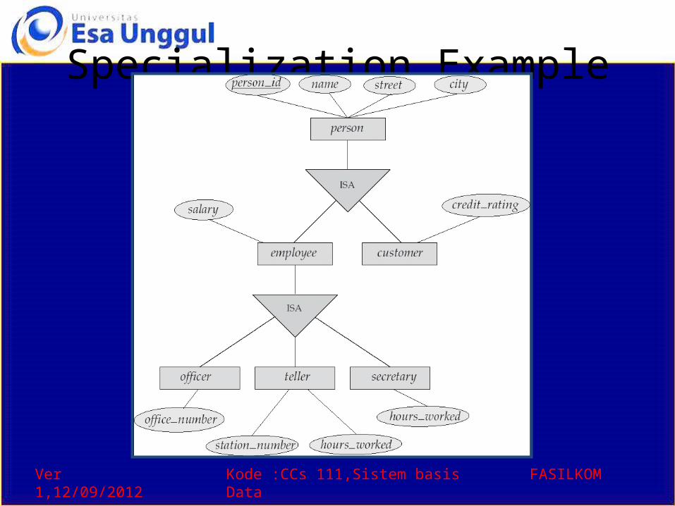
Extended E-R Features: Specialization• Top-down design process; we designate subgroupings within
an entity set that are distinctive from other entities in the set.• These subgroupings become lower-level entity sets that have
attributes or participate in relationships that do not apply to the higher-level entity set.
• Depicted by a triangle component labeled ISA (E.g. customer “is a” person).
• Attribute inheritance – a lower-level entity set inherits all the attributes and relationship participation of the higher-level entity set to which it is linked.
Ver 1,12/09/2012 Kode :CCs 111,Sistem basis Data FASILKOM
Specialization Example
Ver 1,12/09/2012 Kode :CCs 111,Sistem basis Data FASILKOM
Extended ER Features: Generalization• A bottom-up design process – combine a number of entity
sets that share the same features into a higher-level entity set.
• Specialization and generalization are simple inversions of each other; they are represented in an E-R diagram in the same way.
• The terms specialization and generalization are used interchangeably.
Ver 1,12/09/2012 Kode :CCs 111,Sistem basis Data FASILKOM
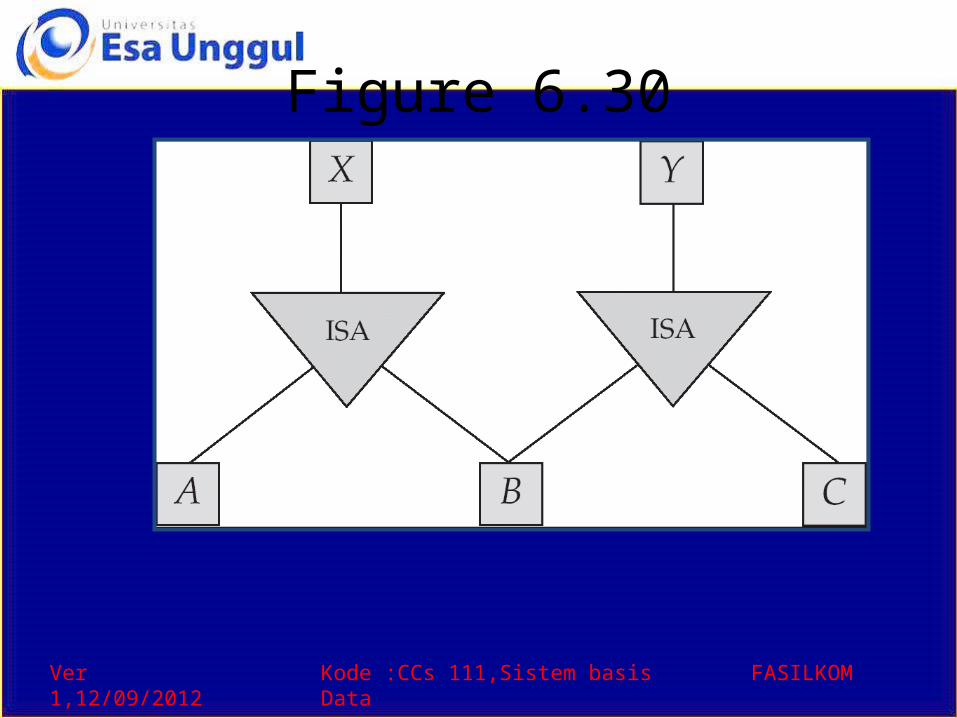
Specialization and Generalization (Cont.)
• Can have multiple specializations of an entity set based on different features.
• E.g. permanent_employee vs. temporary_employee, in addition to officer vs. secretary vs. teller
• Each particular employee would be – a member of one of permanent_employee or
temporary_employee, – and also a member of one of officer, secretary, or teller
• The ISA relationship also referred to as superclass - subclass relationship
Ver 1,12/09/2012 Kode :CCs 111,Sistem basis Data FASILKOM
Design Constraints on a Specialization/Generalization
• Constraint on which entities can be members of a given lower-level entity set.– condition-defined
• Example: all customers over 65 years are members of senior-citizen entity set; senior-citizen ISA person.
– user-defined• Constraint on whether or not entities may belong to
more than one lower-level entity set within a single generalization.– Disjoint
• an entity can belong to only one lower-level entity set• Noted in E-R diagram by writing disjoint next to the ISA triangle
– Overlapping• an entity can belong to more than one lower-level entity set
Ver 1,12/09/2012 Kode :CCs 111,Sistem basis Data FASILKOM
Design Constraints on a Specialization/Generalization (Cont.)
• Completeness constraint -- specifies whether or not an entity in the higher-level entity set must belong to at least one of the lower-level entity sets within a generalization.– total : an entity must belong to one of the lower-level
entity sets– partial: an entity need not belong to one of the lower-
level entity sets
Ver 1,12/09/2012 Kode :CCs 111,Sistem basis Data FASILKOM
Aggregation
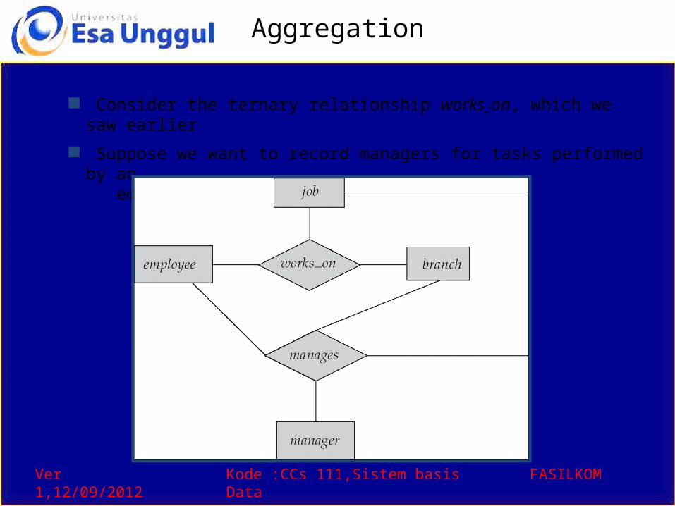
Consider the ternary relationship works_on, which we saw earlier
Suppose we want to record managers for tasks performed by an employee at a branch
Ver 1,12/09/2012 Kode :CCs 111,Sistem basis Data FASILKOM
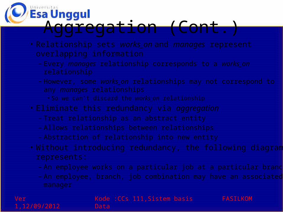
Aggregation (Cont.)• Relationship sets works_on and manages represent overlapping
information– Every manages relationship corresponds to a works_on relationship– However, some works_on relationships may not correspond to any
manages relationships • So we can’t discard the works_on relationship
• Eliminate this redundancy via aggregation– Treat relationship as an abstract entity– Allows relationships between relationships – Abstraction of relationship into new entity
• Without introducing redundancy, the following diagram represents:– An employee works on a particular job at a particular branch – An employee, branch, job combination may have an associated manager
Ver 1,12/09/2012 Kode :CCs 111,Sistem basis Data FASILKOM
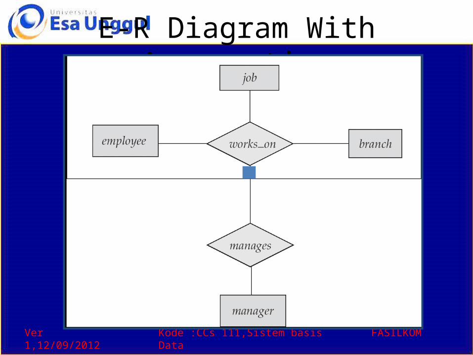
E-R Diagram With Aggregation
Ver 1,12/09/2012 Kode :CCs 111,Sistem basis Data FASILKOM
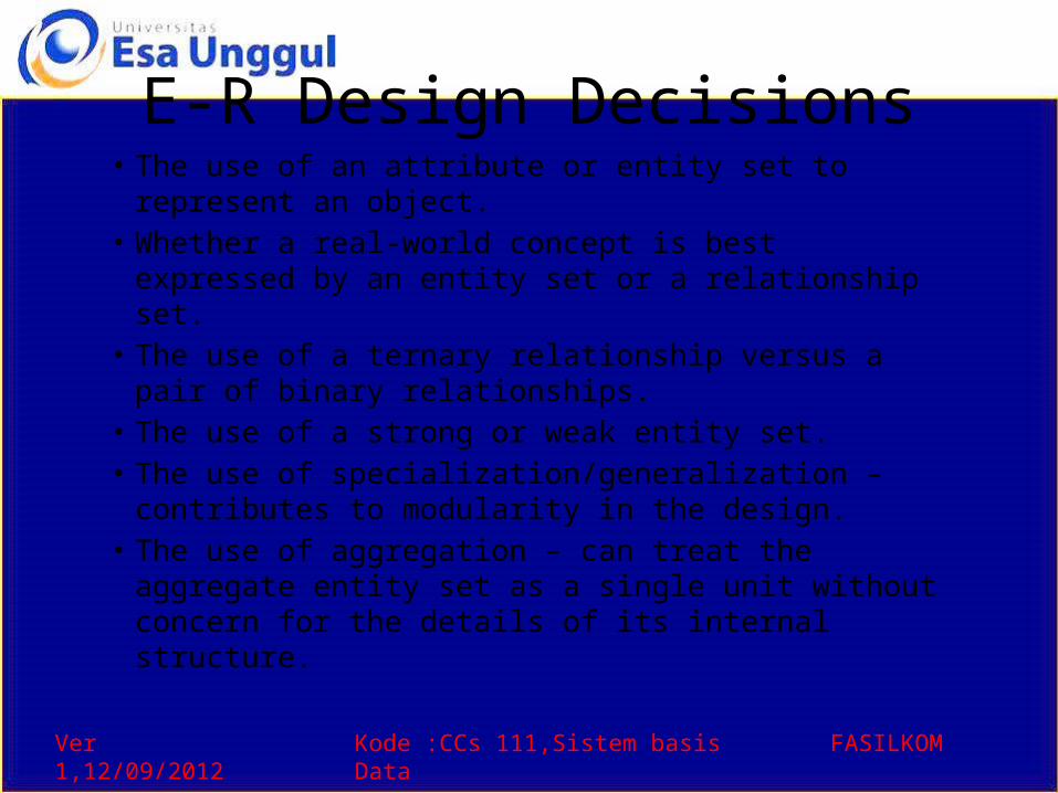
E-R Design Decisions• The use of an attribute or entity set to represent an
object.• Whether a real-world concept is best expressed by an
entity set or a relationship set.• The use of a ternary relationship versus a pair of binary
relationships.• The use of a strong or weak entity set.• The use of specialization/generalization – contributes to
modularity in the design.• The use of aggregation – can treat the aggregate entity
set as a single unit without concern for the details of its internal structure.
Ver 1,12/09/2012 Kode :CCs 111,Sistem basis Data FASILKOM
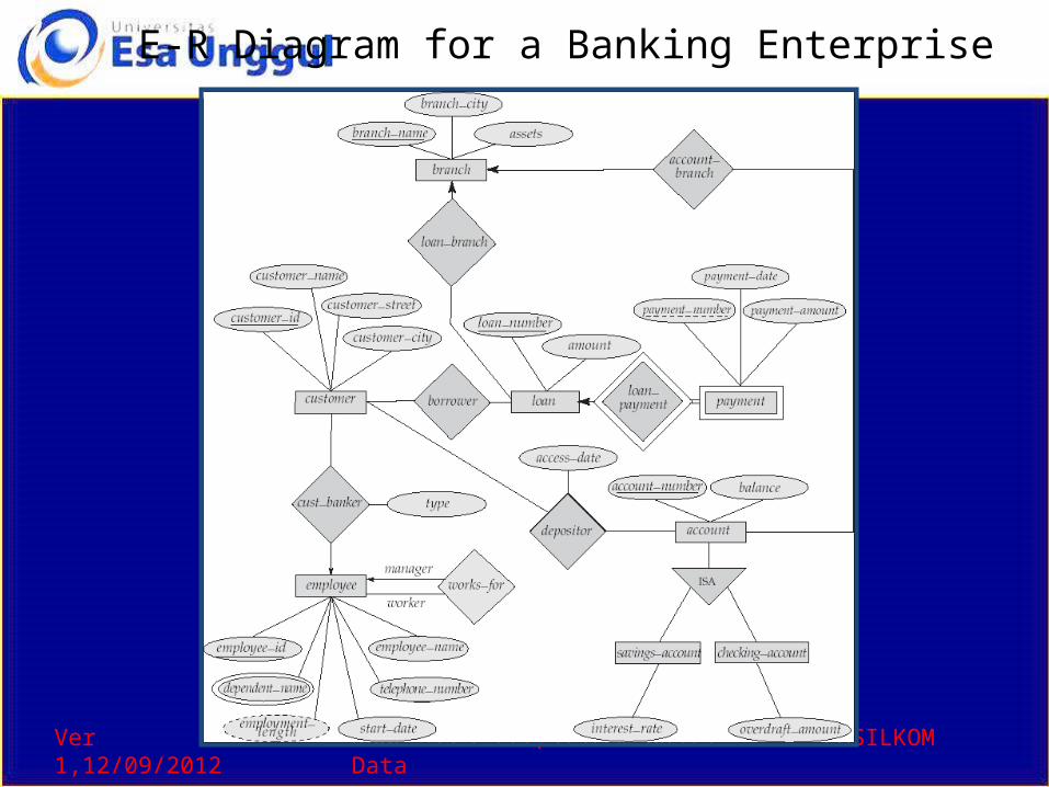
E-R Diagram for a Banking Enterprise

Ver 1,12/09/2012 Kode :CCs 111,Sistem basis Data FASILKOM
How about doing another ER design interactively on the board?
Ver 1,12/09/2012 Kode :CCs 111,Sistem basis Data FASILKOM
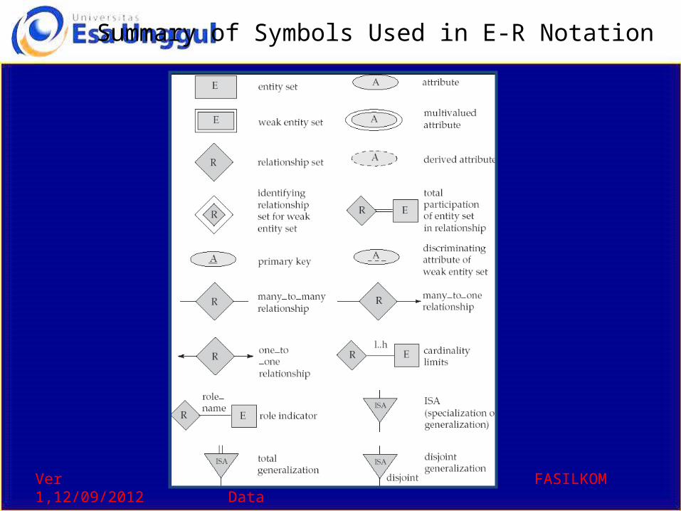
Summary of Symbols Used in E-R Notation
Ver 1,12/09/2012 Kode :CCs 111,Sistem basis Data FASILKOM
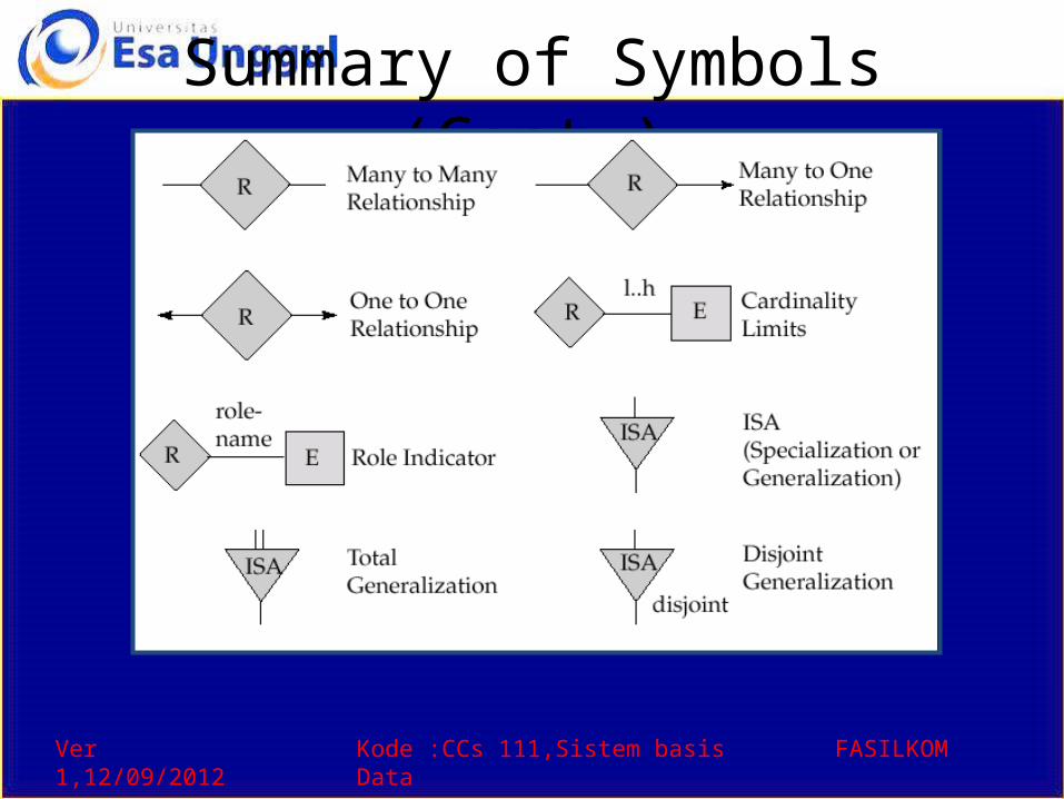
Summary of Symbols (Cont.)
Ver 1,12/09/2012 Kode :CCs 111,Sistem basis Data FASILKOM
Reduction to Relation Schemas
• Primary keys allow entity sets and relationship sets to be expressed uniformly as relation schemas that represent the contents of the database.
• A database which conforms to an E-R diagram can be represented by a collection of schemas.
• For each entity set and relationship set there is a unique schema that is assigned the name of the corresponding entity set or relationship set.
• Each schema has a number of columns (generally corresponding to attributes), which have unique names.
Ver 1,12/09/2012 Kode :CCs 111,Sistem basis Data FASILKOM
Representing Entity Sets as Schemas• A strong entity set reduces to a schema with the same attributes.• A weak entity set becomes a table that includes a column for the primary
key of the identifying strong entity setpayment = ( loan_number, payment_number, payment_date, payment_amount )
Ver 1,12/09/2012 Kode :CCs 111,Sistem basis Data FASILKOM
Representing Relationship Sets as Schemas• A many-to-many relationship set is represented as a schema with
attributes for the primary keys of the two participating entity sets, and any descriptive attributes of the relationship set.
• Example: schema for relationship set borrowerborrower = (customer_id, loan_number )
Ver 1,12/09/2012 Kode :CCs 111,Sistem basis Data FASILKOM
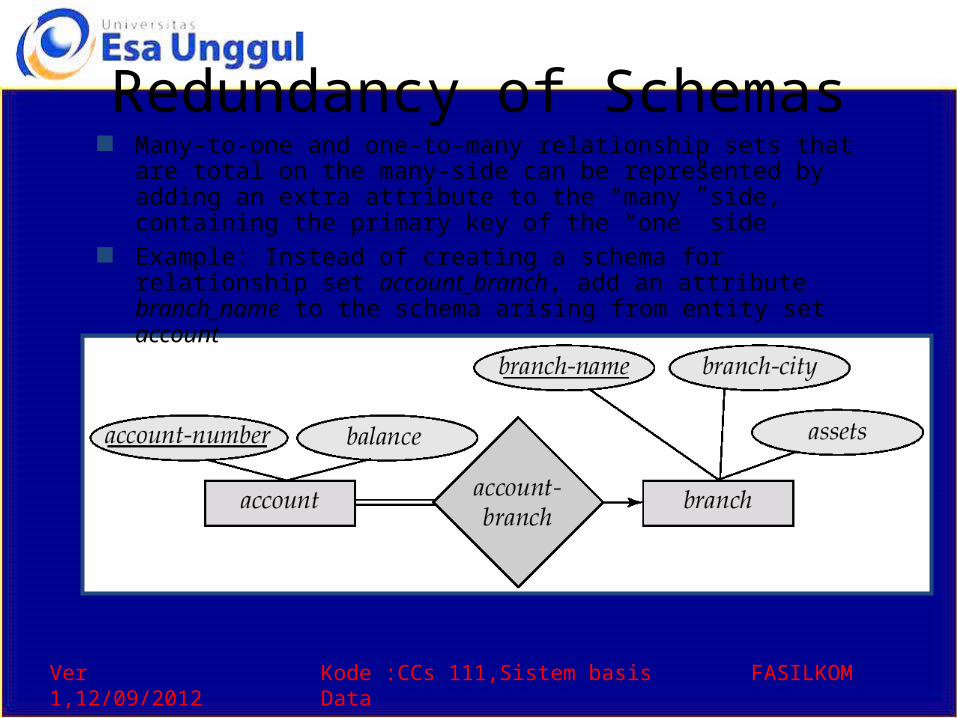
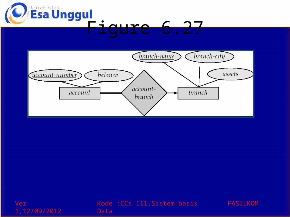
Redundancy of Schemas Many-to-one and one-to-many relationship sets that are total on the
many-side can be represented by adding an extra attribute to the “many” side, containing the primary key of the “one” side
Example: Instead of creating a schema for relationship set account_branch, add an attribute branch_name to the schema arising from entity set account
Ver 1,12/09/2012 Kode :CCs 111,Sistem basis Data FASILKOM
Redundancy of Schemas (Cont.)• For one-to-one relationship sets, either side
can be chosen to act as the “many” side– That is, extra attribute can be added to either of
the tables corresponding to the two entity sets • If participation is partial on the “many” side,
replacing a schema by an extra attribute in the schema corresponding to the “many” side could result in null values
• The schema corresponding to a relationship set linking a weak entity set to its identifying strong entity set is redundant.– Example: The payment schema already contains
the attributes that would appear in the loan_payment schema (i.e., loan_number and payment_number).
Ver 1,12/09/2012 Kode :CCs 111,Sistem basis Data FASILKOM
Composite and Multivalued Attributes
• Composite attributes are flattened out by creating a separate attribute for each component attribute– Example: given entity set customer with
composite attribute name with component attributes first_name and last_name the schema corresponding to the entity set has two attributes name.first_name and name.last_name
• A multivalued attribute M of an entity E is represented by a separate schema EM– Schema EM has attributes corresponding to the
primary key of E and an attribute corresponding to multivalued attribute M
– Example: Multivalued attribute dependent_names of employee is represented by a schema: employee_dependent_names = ( employee_id, dname)
– Each value of the multivalued attribute maps to a separate tuple of the relation on schema EM
• For example, an employee entity with primary key 123-45-6789 and dependents Jack and Jane maps to two tuples: (123-45-6789 , Jack) and (123-45-6789 , Jane)
Ver 1,12/09/2012 Kode :CCs 111,Sistem basis Data FASILKOM
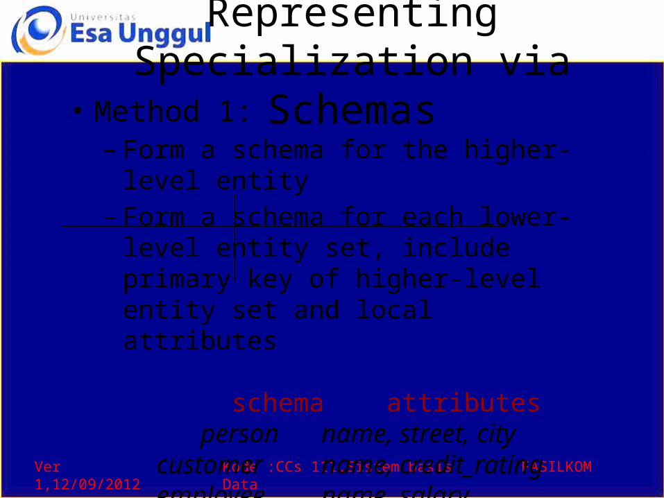
Representing Specialization via Schemas
• Method 1: – Form a schema for the higher-level entity – Form a schema for each lower-level entity
set, include primary key of higher-level entity set and local attributes
schema attributes person name, street, city customer name, credit_rating employee name, salary
– Drawback: getting information about, an employee requires accessing two relations, the one corresponding to the low-level schema and the one corresponding to the high-level schema
Ver 1,12/09/2012 Kode :CCs 111,Sistem basis Data FASILKOM
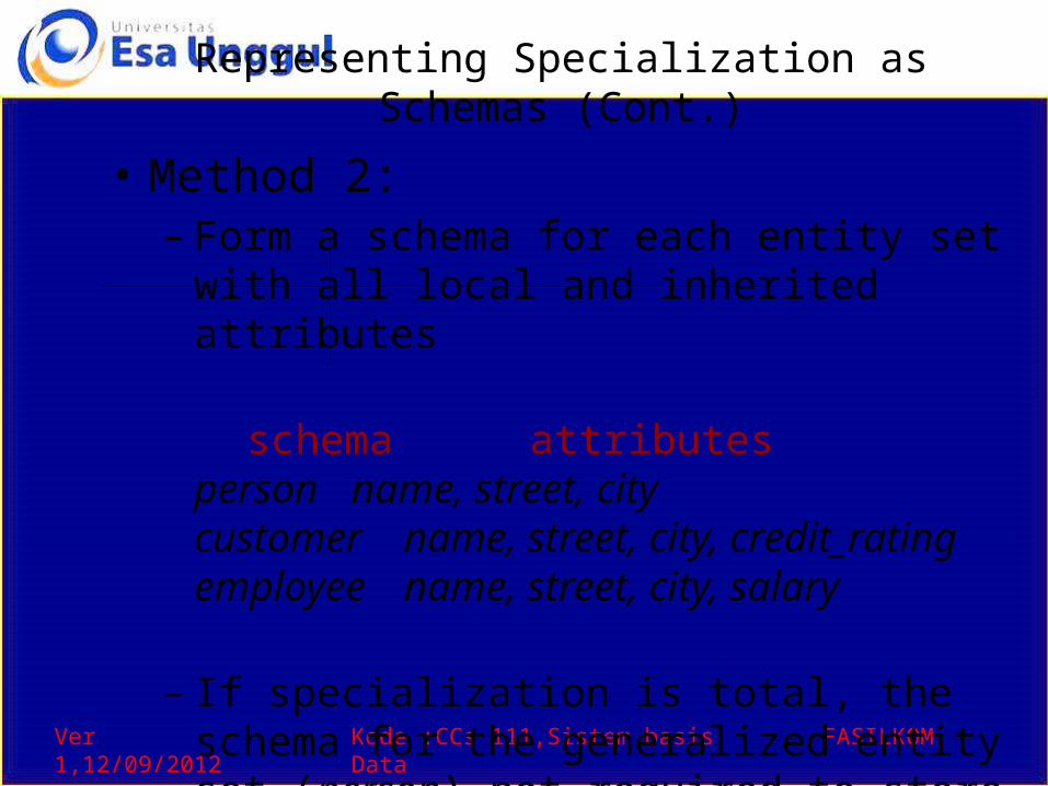
Representing Specialization as Schemas (Cont.)
• Method 2: – Form a schema for each entity set with all local and
inherited attributes
schema attributesperson name, street, citycustomer name, street, city, credit_ratingemployee name, street, city, salary
– If specialization is total, the schema for the generalized entity set (person) not required to store information
• Can be defined as a “view” relation containing union of specialization relations
• But explicit schema may still be needed for foreign key constraints
– Drawback: street and city may be stored redundantly for people who are both customers and employees
Ver 1,12/09/2012 Kode :CCs 111,Sistem basis Data FASILKOM
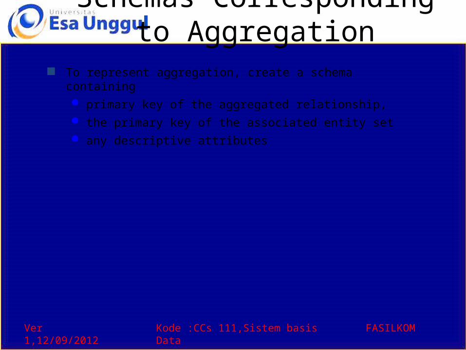
Schemas Corresponding to Aggregation
To represent aggregation, create a schema containing primary key of the aggregated relationship, the primary key of the associated entity set any descriptive attributes
Ver 1,12/09/2012 Kode :CCs 111,Sistem basis Data FASILKOM
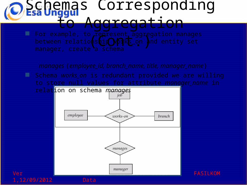
Schemas Corresponding to Aggregation (Cont.) For example, to represent aggregation manages between
relationship works_on and entity set manager, create a schema
manages (employee_id, branch_name, title, manager_name) Schema works_on is redundant provided we are willing to store null
values for attribute manager_name in relation on schema manages
Ver 1,12/09/2012 Kode :CCs 111,Sistem basis Data FASILKOM
UML• UML: Unified Modeling Language• UML has many components to graphically
model different aspects of an entire software system
• UML Class Diagrams correspond to E-R Diagram, but several differences.
Ver 1,12/09/2012 Kode :CCs 111,Sistem basis Data FASILKOM
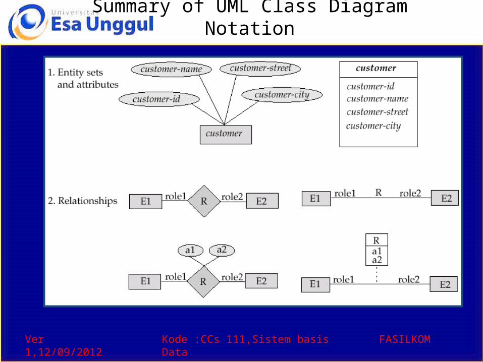
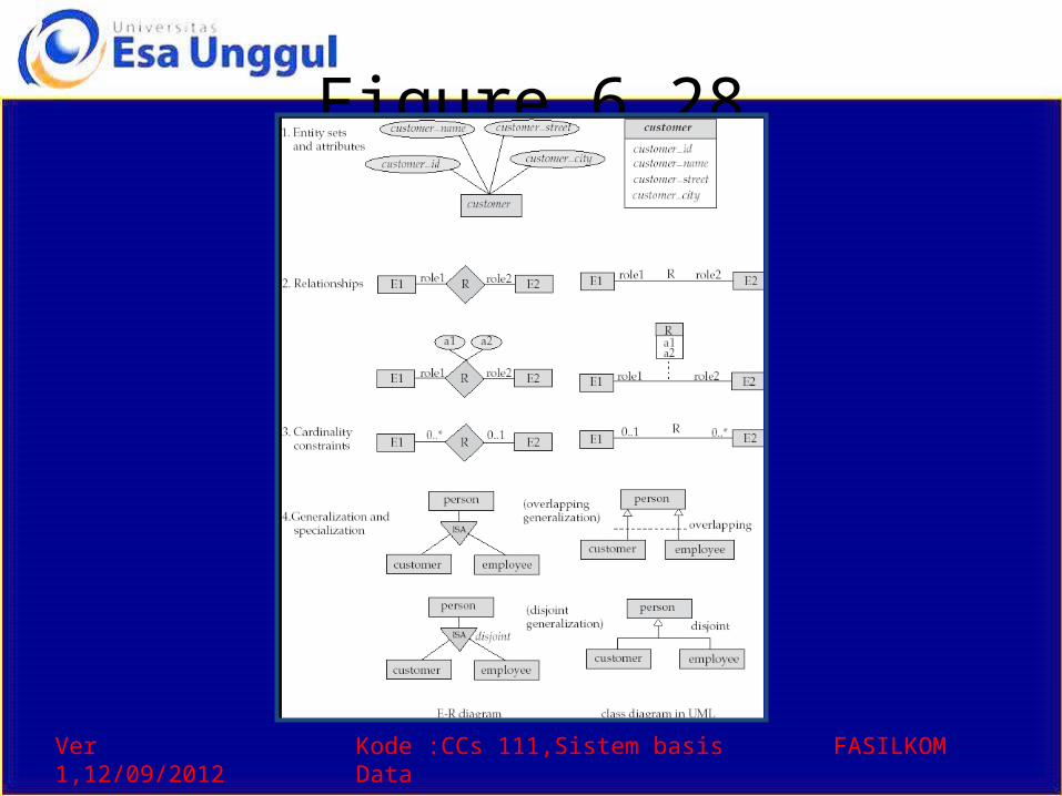
Summary of UML Class Diagram Notation
Ver 1,12/09/2012 Kode :CCs 111,Sistem basis Data FASILKOM
UML Class Diagrams (Cont.)• Entity sets are shown as boxes, and
attributes are shown within the box, rather than as separate ellipses in E-R diagrams.
• Binary relationship sets are represented in UML by just drawing a line connecting the entity sets. The relationship set name is written adjacent to the line.
• The role played by an entity set in a relationship set may also be specified by writing the role name on the line, adjacent to the entity set.
• The relationship set name may alternatively be written in a box, along with attributes of the relationship set, and the box is connected, using a dotted line, to the line depicting the relationship set.
• Non-binary relationships drawn using diamonds, just as in ER diagrams
Ver 1,12/09/2012 Kode :CCs 111,Sistem basis Data FASILKOM
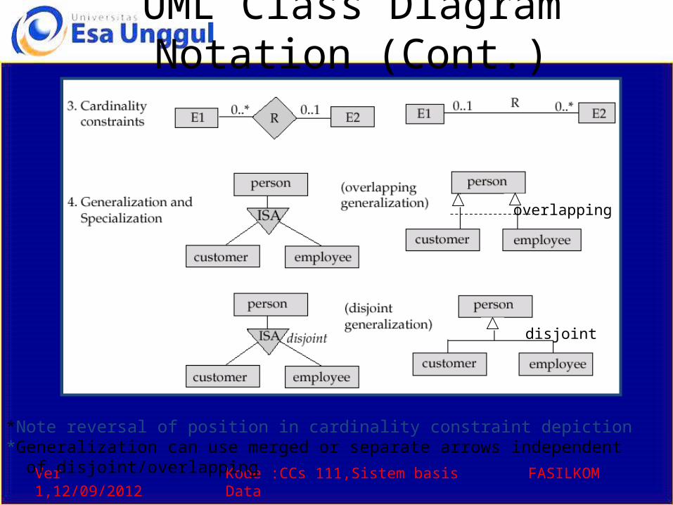
UML Class Diagram Notation (Cont.)
*Note reversal of position in cardinality constraint depiction*Generalization can use merged or separate arrows independent of disjoint/overlapping
overlapping
disjoint
Ver 1,12/09/2012 Kode :CCs 111,Sistem basis Data FASILKOM
UML Class Diagrams (Contd.)
• Cardinality constraints are specified in the form l..h, where l denotes the minimum and h the maximum number of relationships an entity can participate in.
• Beware: the positioning of the constraints is exactly the reverse of the positioning of constraints in E-R diagrams.
• The constraint 0..* on the E2 side and 0..1 on the E1 side means that each E2 entity can participate in at most one relationship, whereas each E1 entity can participate in many relationships; in other words, the relationship is many to one from E2 to E1.
• Single values, such as 1 or * may be written on edges; The single value 1 on an edge is treated as equivalent to 1..1, while * is equivalent to 0..*.
Ver 1,12/09/2012 Kode :CCs 111,Sistem basis Data FASILKOM
End of Chapter 2
Ver 1,12/09/2012 Kode :CCs 111,Sistem basis Data FASILKOM
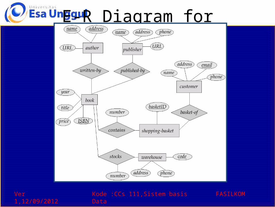
E-R Diagram for Exercise 2.10

Ver 1,12/09/2012 Kode :CCs 111,Sistem basis Data FASILKOM
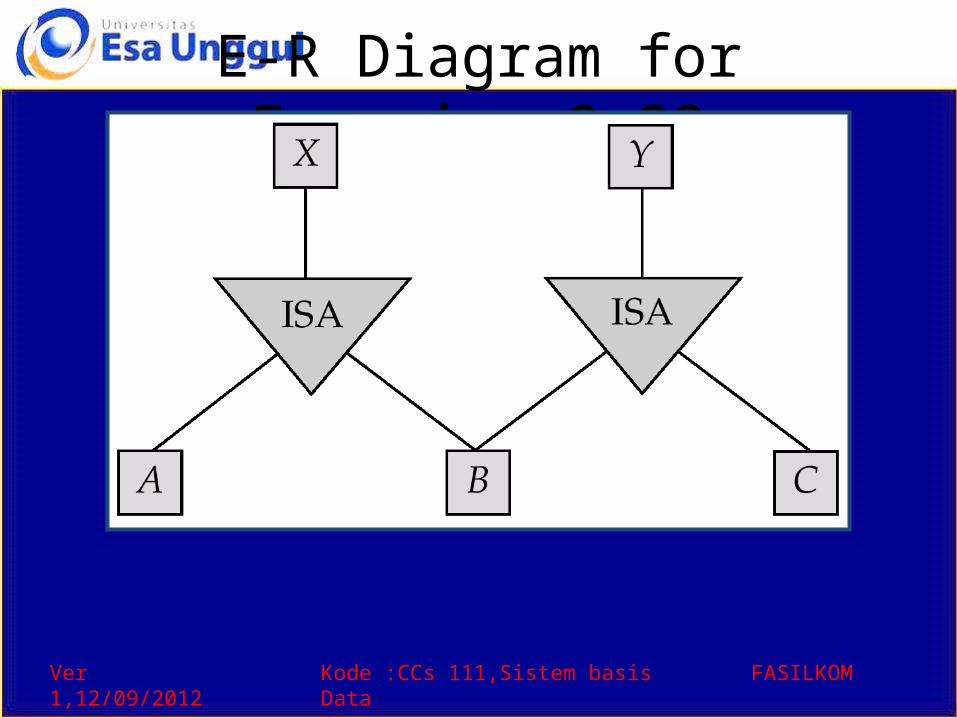
E-R Diagram for Exercise 2.15
Ver 1,12/09/2012 Kode :CCs 111,Sistem basis Data FASILKOM
E-R Diagram for Exercise 2.22
Ver 1,12/09/2012 Kode :CCs 111,Sistem basis Data FASILKOM
E-R Diagram for Exercise 2.15
Ver 1,12/09/2012 Kode :CCs 111,Sistem basis Data FASILKOM
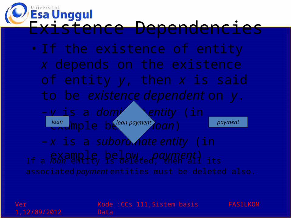
Existence Dependencies• If the existence of entity x depends on
the existence of entity y, then x is said to be existence dependent on y.– y is a dominant entity (in example below,
loan)– x is a subordinate entity (in example below,
payment)
loan-payment paymentloan
If a loan entity is deleted, then all its associated payment entities must be deleted also.
Ver 1,12/09/2012 Kode :CCs 111,Sistem basis Data FASILKOM
Figure 6.8
Ver 1,12/09/2012 Kode :CCs 111,Sistem basis Data FASILKOM
Figure 6.15
Ver 1,12/09/2012 Kode :CCs 111,Sistem basis Data FASILKOM
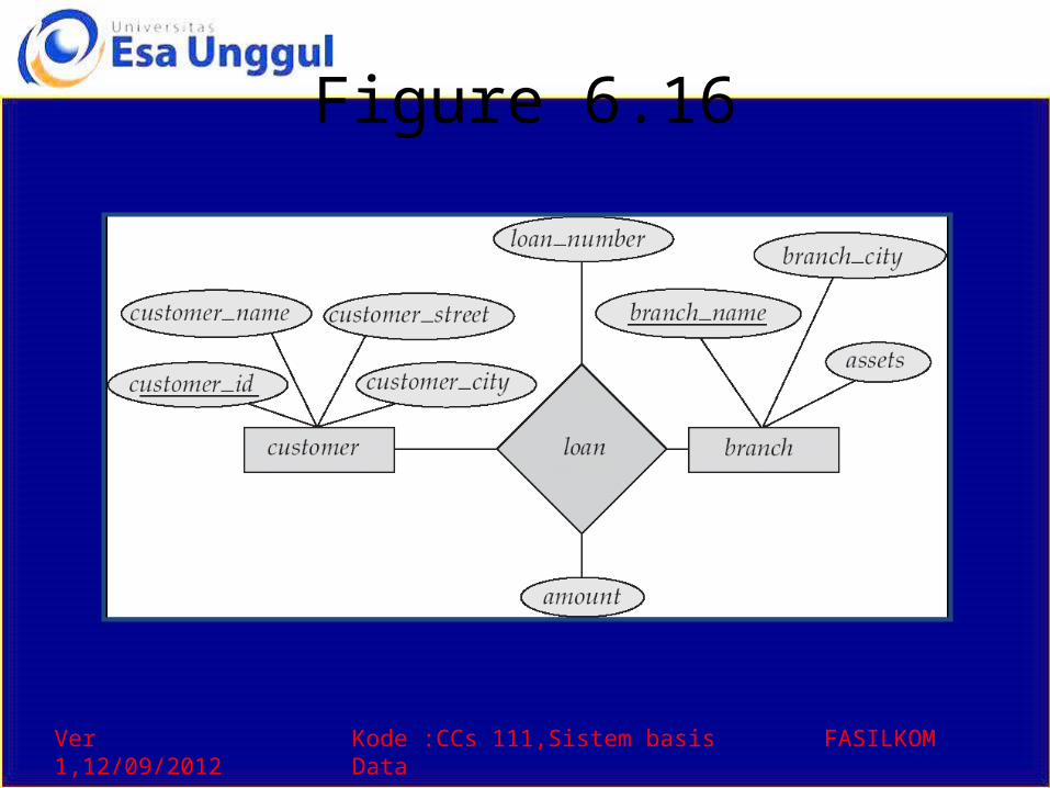
Figure 6.16
Ver 1,12/09/2012 Kode :CCs 111,Sistem basis Data FASILKOM
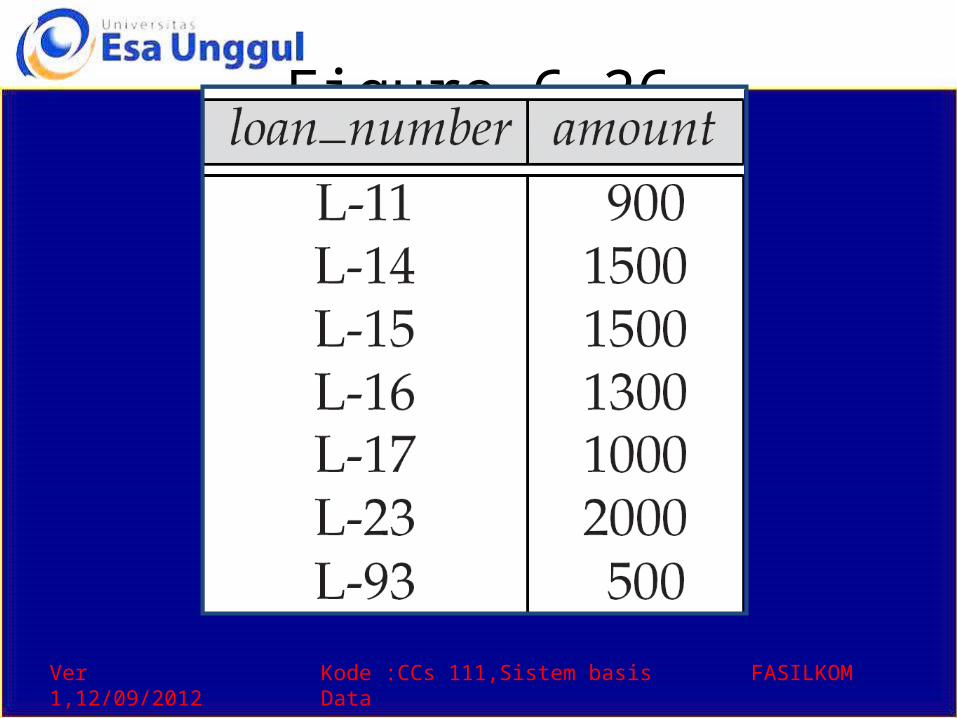
Figure 6.26
Ver 1,12/09/2012 Kode :CCs 111,Sistem basis Data FASILKOM
Figure 6.27
Ver 1,12/09/2012 Kode :CCs 111,Sistem basis Data FASILKOM
Figure 6.28
Ver 1,12/09/2012 Kode :CCs 111,Sistem basis Data FASILKOM
Figure 6.29
Ver 1,12/09/2012 Kode :CCs 111,Sistem basis Data FASILKOM
Figure 6.30
Ver 1,12/09/2012 Kode :CCs 111,Sistem basis Data FASILKOM
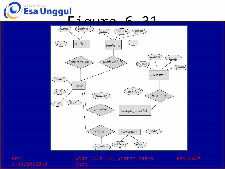
Figure 6.31
Ver 1,12/09/2012 Kode :CCs 111,Sistem basis Data FASILKOM
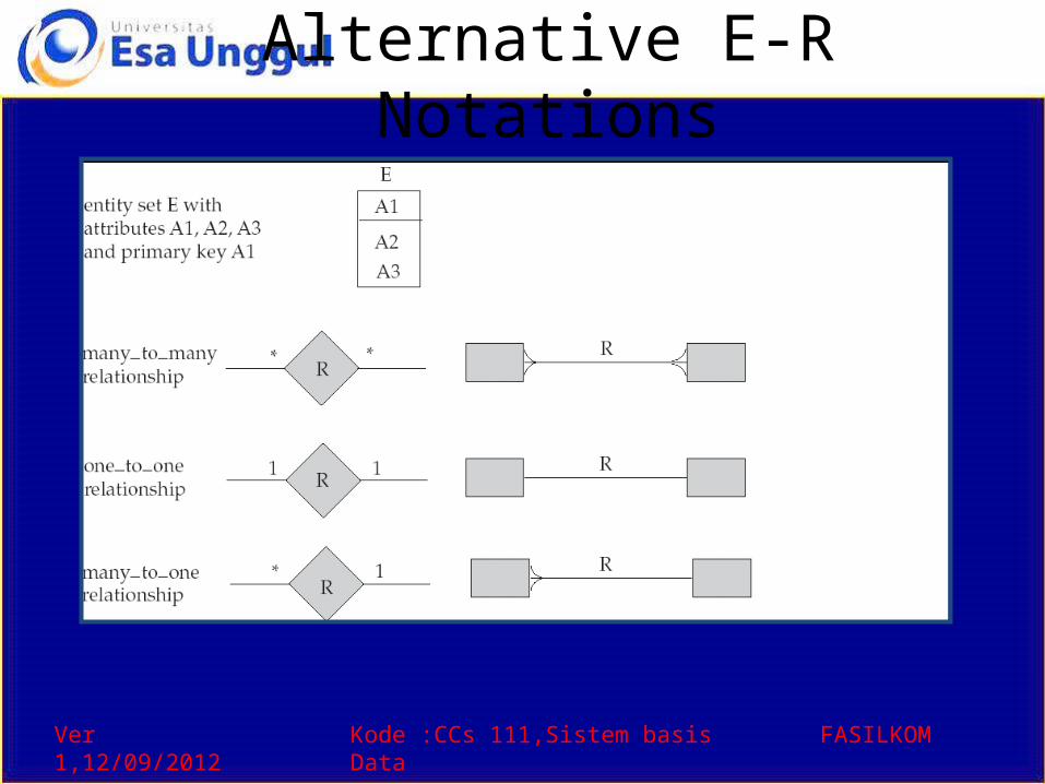
Alternative E-R NotationsFigure 6.24


![[2].Transaction From Sixth Edition Korth](https://img.pdfslide.us/doc/110x75/577cd49f1a28ab9e7898da5a/2transaction-from-sixth-edition-korth.jpg)