Embed Size (px)
Citation preview

VENTILATORI PER ESTRAZIONEFUMI D’INCENDIOSmokeextractfans
11
La vent i laz ione made in I ta ly
Il software di selezione BLOWDYN consente di individuare in modo semplice e veloce il prodotto DYNAIR® più idoneo per realizzare qualsiasi installazione di ventilazione.BLOWDYN is the fan selection software that allows to select the most suitable product for any ventilation project
L'offerta DYNAIR® risponde alle richieste di un mercato in continua evoluzione ed è per questo che uno dei nostri punti di forza consiste nel seguire passo per passo lo sviluppo di un progetto in stretta collaborazione con il cliente, proponendo soluzioni personalizzate e tecnicamente di avanguardia.Living in a market in continuous evolution, DYNAIR® bases its force on a step by step project follow-up in close collaboration with the customer to create tailored and highly reliable solutions.
I nostri ingegneri si avvalgono dell'esperienza maturata negli anni, dell'assistenza dell'Uffi -cio Tecnico e di un supporto tecnologicamente evoluto come il Software CFD (Computational Fluid Dynamics) in grado di simulare tutte le va-riabili fl uido-dinamiche e quindi le condizioni di impiego di un impianto di ventilazione.The consolidated experience in product applica-tion of our Engineers is supported by the high-skilled assistance of the technical department and by advanced technological means such as the CFD software, designed to elaborate all fl uid dynamic variables and simulate the real working conditions of any ventilation system.
DYNAIR® è la divisione industriale di Maico Italia S.p.A. e un marchio affermato a livello mondiale nel settore della ventilazione industriale ed impiantistica. Competenza tecnologica, elevata capacità produttiva, decisa politica di ricerca e di investimento unite ad un servizio di supporto personalizzato focalizzato sulle esigenze del cliente sono, da più di 30 anni, le qualità che contraddistinguono la nostra offerta: un’eccellenza italiana oggi riconosciuta in tutto il mondo e una realtà industriale forte della sua appartenenza a Maico Holding GmbH, gruppo tedesco leader nel campo della ventilazione.
DYNAIR® is the industrial division of Maico Italia S.p.A. and is a well-known brand name at global level in the industrial ventilation and plant engineering sector. Technological expertise, high production capacities, strong research and investment policies together with a personalised back-up service focused on customer needs have, for over 30 years, been the qualities that distinguish our company: Italian excellence renowned throughout the world and an industrial reality fortifi ed by belonging to Maico Holding GmbH, the German group that leads the way in the ventilation industry.
Esperienza e tecnologia a vostro servizioExperienceandhightechnologyatyourservice
www.dynair.it Ultime novità / Latestnews Cataloghi on-line / On-linecatalogues Focus tematici / Thematicfocus Software Blowdyn

3
11sezionepart
Ventilatori per estrazione fumi d’incendioSmokeextractfans
Ventilatori assiali ad impulso per autorimesse F200 - F300/120Impulse fans for car park ventilation F200 - F300/120
CC-JD HT pag. 5
Torrini d’estrazione centrifughi a doppia velocità F400Double speed centrifugal roof fans F400
FC HT-2V pag. 17
Ventilatori centrifughi pale rovesce a doppia velocità F400Double speed backward curved blade centrifugal fans F400
PR-Q HT-2V pag. 24
Accessori / Accessories pag. 32
Ventilatori assiali intubati ad alte prestazioni F200 - F300/120 - F400High performance duct axial fans F200 - F300/120 - F400
CC HT pag. 16
Ventilatori centrifughi ad induzione per autorimesse F300/120Centrifugal induction fans for car park ventilation F300/120
CC-JC HT pag. 7
Ventilatori assiali intubati ad alta effi cienza F300/120 - F400High effi ciency duct axial fans F300/120 - F400
CC SHT pag. 9
Torrini d’estrazione centrifughi a scarico verticale F400Centrifugal roof fans vertical discharge F400
TC HT pag. 20
Ventilatori cassonati a doppia aspirazione a trasmissione F400belt driven double inlet box fans F400
BOX-T HT pag. 28
Guida alla ventilazione di autorimesseGuidelinestocarparkventilation
pag. 38

4
INTRODUZIONEI sistemi di ventilazione meccanica progettati da Dynair® presentati in questa sezione sono la risposta ai problemi legati all’evacuazione di fumi ad alta temperatura, ideali quindi per l’aspirazione d’emergenza in caso d’incendio (soluzione impiantistica resa obbligatoria dalle normative di quasi tutti i paesi).
DIVERSI SONO I FATTORI POTENZIALI DI RISCHIODERIVANTI DA UN INCENDIO:
• produzione di gas e sostanze tossiche prodotti dalla combustione, con effetti di lacrimazione ed incapacità di fuga;
• sviluppo di fumo (sospensione di cenere nell’aria) con conseguente visibilità ridotta o impedita;
• sviluppo di alte temperature;
• diminuzione dell’ossigeno necessario all’incendio e aumento del monossido di carbonio con effetti quali la perdita di conoscenza e la morte per asfi ssia (secondo le statistiche più dei 2/3 delle vittime degli incendi muoiono a causa di soffocamento o avvelenamento da fumo).
FUNZIONI E VANTAGGI DELLA VENTILAZIONE FORZATAIN CASO DI INCENDIO:
1) Permette la rimozione dei fumi di incendio e la messa in depressione del locale impedendo l’invasione da parte dei fumi di altri locali.
Questo crea le migliori condizioni di fuga degli occupanti e facilita l’individuazione del focolaio da parte dei vigili del fuoco.
2) Contribuisce a mantenere una temperatura ambiente relativamente bassa (300°-400°C), mentre in caso di ambiente sigillato si possono superare facilmente i 1000° C, provocando la combustione di qualsiasi materiale per il solo calore radiante, condizione che renderebbe inutile qualsiasi intervento di spegnimento esterno.
Riuscire a mantenere una temperatura relativamente bassa signifi ca evitare il collasso delle strutture statiche portanti del locale.
Inoltre la maggior percentuale di ossigeno provoca una migliore combustione con conseguente minor produzione di fumi tossici.
3) Permette la dislocazione dei punti di apertura in luoghi diversi da quello controllato, essendo alcuni ventilatori facilmente canalizzabili.
4) Consente l’estrazione dei fumi freddi, che stratifi candosi a basso livello sono estremamente dannosi per le persone e di diffi cilissima estrazione da parte dei sistemi non meccanici.
5) Permette la ventilazione dei locali anche in situazioni di normale attività (aria pulita) con la possibilità di utilizzare il motore a doppia velocità, ad esempio bassa velocità, con relativa minore rumorosità, per ventilazione normale ed alta velocità per situazioni d’emergenza. Naturalmente è necessario realizzare una linea elettrica di alimentazione dedicata e che funzioni automaticamente in caso di incendio.
INTRODUCTIONThe mechanical ventilation systems designed by Dynair® which are presented in this part, are the answer to problems connected to smoke extraction at high temperature and the ideal solution for emergency exhaust in case of fi re (a solution mandatory in fi re safety norms of most countries).
THERE ARE DIFFERENT POTENTIAL RISKELEMENTS SUBSEQUENT TO A FIRE:
• the release of gas and toxic substances produced by the combustion which creates lachrymation and impossibility to escape;
• the diffusion of fi re (the stay of ashes in the air) which leads to a reduced or an impossible visibility;
• the diffusion of very high temperature;
• the reduction of the oxygen needed by the fi re and the increase of carbon monoxide in the air which lead to lose consciousness and to a death by lack of oxygen (according to statistics, more than 2/3 of fi re victims die because of suffocation or poisoning by fi re fumes).
FUNCTION AND ADVANTAGES OF MECHANICALVENTILATION IN CASE OF FIRE:
1) The mechanical ventilation removes fumes and puts in depression the premise, thus preventing the diffusion of smoke into other rooms. This creates better conditions for the escape of the occupants and simplify the job of the fi remen.
2) In case of closed premises, it is possible to easily exceed 1000° C, causing the combustion of any material just for heat radiation: a condition that would make useless any external extinguish operation. To keep the temperature relatively low (300°- 400° C) by extracting hot air, means to avoid the collapse of the support structures. In addition, the higher oxygen rate will cause a better combustion and thus, for most materials, a lower production of toxic smoke.
3) The mechanical ventilation allows the location of the exhaust outlets in places away from the one involved, being the CC-HT series easy to be connected to a duct sysem.
4) The mechanical ventilation allows the extraction of cold fumes, which, remaining at lower level, are extremely dangerous for the occupants and very diffi cult to be removed by static systems.
5) The mechanical ventilation allows the ventilation of the premises also in normal activity situations (clean air), thanks to the possibility of fi tting double speed motors: at low speed for normal ventilation (so with lower noise level) and at high speed for emergency conditions. Obviuosly it is necessary to install the fan with a dedicated power line that automatically operates in case of fi re.
La regolamentazione della progettazione e dell’installazione dei ventilatori antincendio è inquadrata dalla normativa di riferimento a livello europeo, la EN 12101-3, che stabilisce le classi di temperatura/durata alle quali devono rispondere i prodotti certifi cati.La gamma HT DYNAIR è certifi cata CE in classi F200, F300/120, F400 secondo la EN12101-3 dai laboratori indipendenti e autonomi APPLUS di Barcellona e TUM di Monaco di Baviera a seconda delle serie e dei modelli (vedere singole pagine prodotto).
Fire fi ghting fan design and installation is regulated by the European reference standard EN 12101-3, which establishes the temperature ranges/operation time certifi ed products must comply with. DYNAIR HT range is CE certifi ed to class F200, F300/120, F400 in compliance with EN12101-3 standard by the indipendent and notifi ed laboratories APPLUS in Barcelona and TUM in Munich according to the series and models (see single products presentation).
L’ESTRAZIONE DEI FUMI D’INCENDIOSmokeextract

5
CC-JD HT JET FANS Ventilatori assiali ad impulso per autorimesse F200 - F300/120 Certifi cati secondo la EN 12101-3JETFANSImpulsefansforcarparkventilationF200-F300/120CertifiedaccordingtoEN12101-3
DESCRIZIONEVentilatori assiali intubati ad impulso progettati e omologati per l’evacuazione dei fumi e gas caldi che si sprigionano durante un incendio nelle au-torimesse chiuse. I CC-JD HT sono apparecchi “dual purpose” ossia adatti sia all’estrazione dei fumi antincendio sia alla ventilazione normale dei parcheggi (rimozione CO).
Nella confi gurazione standard per la ventilazio-ne normale (estrazione CO), la serie è idonea al funzionamento alla temperatura di +60°C.I modelli HT per l’estrazione dei fumi d’incen-dio sono certifi cati CE in classe F200, F300 se-condo la Normativa EN12101-3 e garantiti per funzionamento a 300°C/2 ore dall’ente terzo autonomo e qualifi cato Applus.
La tecnologia specifi ca dei ventilatori a getto e ad induzione (CC-JC) rappresenta l’alternativa più innovativa ed economica ai tradizionali sistemi di evacuazione meccanica canalizzata, in particola-re per quanto riguarda la riduzione drastica dei costi di installazione (completa eliminazione di complessi e costosi sistemi di condotti e griglie) e le notevoli economie di esercizio derivanti dalle peculiarità del sistema che permette di ven-tilare o estrarre solo in alcune zone del garage o solo se è necessario.
COSTRUZIONE• Silenziatori in lamiera zincata rivestiti interna-
mente con materiale altamente fonoassorbente. • Defl ettore lato espulsione per ottimizzare il la-
vaggio dell’aria in tutti gli strati. Fornito di serie. • Rete di protezione lato aspirazione. • Staffe di fi ssaggio zincate fornite di serie e pre-
assemblate. • Boccagli propriamente sagomati per facilitare
l’ingresso e l’uscita dell’aria movimentata. • Cassa in lamiera d’acciaio zincata. • Girante con pale a profi lo alare ad alte prestazio-
ni in pressofusione di lega d’alluminio. Bilanciata secondo ISO 1940 G.6.3. Angolo di calettamen-to variabile da fermo.
• Scatola morsettiera IP54 resistente all’alta tem-peratura fornita di serie
MOTOREMotore asincrono trifase 380-420V - 50 Hz a norme internazionali IEC 60034, IEC 60072, EMC 2004/108/CE, LVD 2006/95/CE Adatto all’avvia-mento DOL (direct on line)Marcatura CE. Protetto IP55, classe F o H.Esecuzione 4 (accoppiamento diretto con girante a sbalzo).
A RICHIESTA• Versione per ventilazione normale dei parcheggi (estrazione CO) (CC-JD)• Taglia 350 mm• Versione con fl usso d’aria reversibile al 100%• Interruttore di servizio IP67 garantito per alte temperature, montato.
DESCRIPTIONAxial impulse fans suitable for installation in under-ground car parks and/or tunnels, especially desig-ned and certifi ed for fi re smoke and hot gases ex-traction in case of fi re. CC-JD HT are “dual purpose” fans, i.e. they can provide both normal ventilation (carbon monoxide removal) and smoke extract in case of fi re.
In the standard confi guration for normal venti-lation (CO extract), the series can be used at the temperature of +60°C temperature range. The fi re smoke extraction models (HT) are CE certifi ed to F200, F300 class, in compliance with Standard EN12101-3 and guaranteed to operate at 300°C for 2 hours by the independent notifi ed body Applus.
(CC-JD) The special impulse induction fans tech-nology represent the most innovative and cost-effective alternative to traditional duct mechani-cal extraction systems: the drastic reduction of installation costs (complete removal of ducted and grilled systems) and the considerable run-ning cost savings ensured by the fsystem di-stinctive features (ventilation / extraction can be partial and only if necessary) are only two of the multiple benefi ts of car park ventilation systems based on CC-JD / C fans.
CONSTRUCTION• Silencers in galvanized steel sheet inside lined
with high performance acoustic insulation material.
• Defl ector on outlet side for optimum air discharge and air cleaning of all layers. Supplied as standard.
• Protection guard on inlet side. • Fixing brackets in galvanized steel sheet for cei-
ling (or wall) installation. Supplied as standard and pre-assembled.
• Silencers are fi tted at both ends with an especially designed smooth bell shape to improve air per-formance and reduce losses and sound level.
• Housing in electrolytically galvanized steel sheet. • Hub impeller and airfoil profi le blades made in
aluminium. Balanced according to ISO 1940 G.6.3. Variable pitch angle in still position.
• Terminal box IP54, resistant to high temperature and supplied as standard.
MOTORAsynchronous three-phase motors 380-420V 50 Hz according to international standards IEC 60034, IEC 60072, EMC 2004/108/CE, LVD 2006/95/CE. Motors suitable for DOL (Direct On Line) start. CE marked. Protection IP55, class F or H.Execution 4 (with impeller directly coupled to mo-tor with feet).
UPON REQUEST• Versions for the sole normal ventilation (CO extraction) (CC-JD)• Size 350 mm• Versions with 100% reversible airfl ow• Service switch IP67 for high temperature, assembled
SU RICHIESTA / ON REQUESTInterruttore di servizio IP67, garantito per alte temperature.Sevice switch IP67, tested and gua-ranteed for high temperature.
Scatola morsettiera IP54 resistente all’alta temperatura.Terminal box IP54, resistant to high temperature .
IN DOTAZIONE / SUPPLIED
Certifi cato /Certifi cate nr 0370-CPD-1149
CONSEGNA VELOCE / 3 settimaneQUICK DELIVERY / 3 weeks
F200 F300/120
Consulta la Guida alla ventilazione di autorimessa a pag.38 SeetheGuidelinestocarparkventilationatpage38

6
PRESTAZIONI Performance CC-JD HT
DATI TECNICI TECHNICAL DATA
TipoType
ModelloModel
Velocità Speed Pm In [400V] Tension
50 HzClasse
temperaturaTemperature
classrpm kW A V
CC-JD 312 2830 0,55 1,5 380-420
+60°CCC-JD 402 2825 1,5 3,4 380-420
CC-JD 404 1330 0,18 0,7 380-420
CC-JD 312 HT 2790 0,75 1,57 380-420
F200 - F300300°C/2 ORE
CC-JD 312/4 HT 2820/1400 0,8/0,2 1,91/0,60 380-420
CC-JD 402 HT 2870 1,5 3,01 380-420
CC-JD 402/4 HT 2900/1435 1,5/0,37 3,54/1,25 380-420
CC-JD 404 HT 1430 0,55 1,36 380-420
PRESTAZIONI PERFORMANCE
TipoType
ModelloModel
PortataAirflow
Velocità ariaAir speed
SpintaThrust Lp
m3/s m/s N dB(A) @ 3m
CC-JD 312 1,28 17,3 27 54
CC-JD 402 2,88 22,3 78 58
CC-JD 404 1,44 11,2 20 47
CC-JD 312 HT 1,28 17,3 27 54
CC-JD 312/4 HT 1,28/0,64 17,3/8,7 27/07 54/43
CC-JD 402 HT 2,88 22,3 78 58
CC-JD 402/4 HT 2,88/1,44 22,3/11,2 78/20 58/47
CC-JD 404 HT 1,44 11,2 20 47
DIMENSIONI (mm) DIMENSIONS (mm)
ModelloModel A B ØC D E F G H I Kg
CC-JD 310 415 375 415 240 630 200 134 1595 6 65
CC-JD 400 500 460 500 270 800 230 134 1965 6 80
DIMENSIONI Dimensions
RETE DI PROTEZIONEPROTECTION GRID
DEFLETTOREDEFLECTOR
INTERRUTTORE DI SERVIZIOSERVICE SWITCH
STAFFA DI FISSAGGIOFIXING BRACKETS

7
CC-JC HT Ventilatori centrifughi ad induzione per autorimesse F300/120 Certifi cati secondo la EN 12101-3CentrifugalinductionfansforcarparkventilationF300/120CertifiedaccordingtoEN12101-3
DESCRIZIONEVentilatori centrifughi ad induzione progettati e omologati per l’evacuazione dei fumi e gas caldi che si sprigionano durante un incendio nelle au-torimesse. I CC-JC HT sono apparecchi “dual pur-pose”, ossia adatti sia all’estrazione dei fumi di in-cendio, sia alla ventilazione normale dei parcheggi (rimozione CO). Grazie alle sue ridotte dimensioni d’ingombro, CC-JC è ideale per le autorimesse con forti limitazioni in altezza.
La serie è idonea al funzionamento in servizio continuo alla temperatura di +40°C, é certifi cata CE in classe F300 secondo la Normativa EN12101-3 e garantita per funzionamento a 300°C 2 ore dall’ente terzo autonomo e qualifi cato APPLUS.
La tecnologia specifi ca dei ventilatori a getto (CC-JD) e ad induzione (CC-JC) rappresenta l’alterna-tiva più innovativa ed economica ai tradizionali sistemi di evacuazione meccanica canalizzata, in particolare per quanto riguarda la riduzione dra-stica dei costi di installazione (completa elimina-zione di sistemi di condotti e griglie) e le notevoli economie di esercizio derivanti dalle peculiarità del sistema che permette di ventilare o estrarre solo in alcune zone del garage e solo se necessario.
COSTRUZIONE• Girante a pale rovesce ad alto rendimento in la-
miera zincata equilibrata secondo la ISO 1940.• Struttura in lamiera d’acciaio zincato protetta
contro gli agenti atmosferici.• Rete di protezione lato aspirazione.• Staffe di fi ssaggio a soffi tto/muro in acciaio
zincato fornite in dotazione e pre-assemblate.
MOTOREMotore asincrono trifase 380-420V - 50 Hz a dop-pia polarità idoneo per funzionare alla temperatura di 40°C in servizio continuo e 300°C per 120 minu-ti in caso di emergenza incendio.Marcatura CE. Protetto IP55, Classe H. Adatto a servizio continuo (S1).Esecuzione 5: accoppiamento diretto con girante a sbalzo.
A RICHIESTA• Interruttore di servizio IP67 garantito per alte
temperature, montato
DESCRIPTIONCentrifugal induction fans designed and suitable for installation in underground car parks and/or tunnels, especially designed and certifi ed for fi re smoke and hot gases extraction in case of fi re. CC-JC HT are “dual purpose” fans, i.e. they can provide both normal ventilation (carbon monoxi-de removal) and smoke extract in case of fi re.
The series is suitable for continuous running at the temperature of +40°C and is CE certifi ed to F300 class, in compliance with Standard EN12101-3 and guaranteed to operate at 300°C for 2 hours by the independent notifi ed body Applus
The special impulse (CC-JD) and induction (CC-JC) fans technology represents the most innova-tive and cost-effective alternative to traditional duct mechanical extraction systems: the drastic reduction of installation costs (complete removal of ducted and grilled systems) and the conside-rable running cost savings ensured by the system distinctive features (ventilation / extraction can be partial and only if necessary) are only two of the multiple benefi ts of car park ventilation systems based on CC-JC/D fans.
CONSTRUCTION• Hub impeller and airfoil prof le blades made in
aluminium. Balanced according to ISO 1940.• Housing in electrolytically galvanized steel sheet. • Protection guard on inlet side.• Fixing brackets in galvanized steel sheet for cei-
ling/wall installation supplied pre-assembled.
MOTORAsynchronous three-phase double polarity motor 380-420V - 50 Hz suitable to work up to a maximum temperature of 40°C (service S1) and 300°C for 120 minutes in case of fi re emergency (service S2).CE marked, IP55 protection, Class H. Suitable for continuous running (S1).Execution 5: Impeller directly coupled on the motor shaft.
UPON REQUEST• Service switch IP67 for high temperature, assembled
CONSEGNA VELOCE / 3 settimaneQUICK DELIVERY / 3 weeks
F300/120
Consulta la Guida alla ventilazione di autorimessa a pag.38 SeetheGuidelinestocarparkventilationatpage38

8
PRESTAZIONI Performance CC-JC HT
DATI TECNICI TECHNICAL DATA
TipoType
ModelloModel
Velocità Speed Pm In [400V] Tension
50 HzClasse
temperaturaTemperature
classrpm kW A V
CC-JC 250 4/8 S F300 1400 / 700 1,2 / 0,3 3,3 / 1,43 380 - 420 +40°CF300/120CC-JC 300 4/8 S F300 1400 / 700 2,2 / 0,55 5,8 / 2 380 - 420
PRESTAZIONI PERFORMANCE
TipoType
ModelloModel
PortataAirflow
Velocità ariaAir speed
SpintaThrust Lp
m3/s m/s N dB(A) @ 3m
CC-JC 250 4/8 S F300 1,5 26,9 55,3 70 / 53
CC-JC 300 4/8 S F300 2,7 30 111 71 / 55
DIMENSIONI (mm) DIMENSIONS (mm)
ModelloModel A B C D E F G H Kg
CC-JC 250 930 880 830 196 467 1584 1690 257 125
CC-JC 300 1074 460 1000 180 650 1907 2013 314 162
DIMENSIONI Dimensions
B
DE
A
I
C
F
H
G
INTERRUTTOREINTERRUTTORESERVICE SWITCH

9
CC SHT Ventilatori assiali intubati ad alta effi cienza F300/120 - F400 Certifi cati secondo la EN 12101-3HighefficiencyductaxialfansF300/120-F400CertifiedaccordingtoEN12101-3
DESCRIZIONEVentilatori assiali intubati ad alta effi cienza per applicazioni canalizzate progettati e omologati per l’evacuazione di fumi ad alta temperatura. Specifi catamente progettati in una gamma che consente di soddisfare le prestazioni richieste nei regolamenti tecnici di prevenzione incendi per la progettazione e costruzione di attività commercia-li e nella ventilazione antincendio per l’edilizia.
La serie è idonea al funzionamento alla tem-peratura di +70°C ed è certifi cata F300, F400 secondo la Normativa EN 12101-3 e garantita per funzionamento a 300°C 2 ore dall’ente terzo autonomo e qualifi cato Applus.
COSTRUZIONE• Cassa in lamiera d’acciaio, con fl ange di fi ssag-
gio a norma UNI ISO 6580 – EUROVENT. Verni-ciata a polveri epossidiche.
• Girante ad altissima effi cienza in lega di alluminio dal profi lo ottimizzato che garantisce resisten-za ad alte temperature. Bilanciata secondo ISO 1940. Angolo di calettamento variabile da fermo.
• Esecuzione 4 (accoppiamento diretto con giran-te a sbalzo) e fl usso aria da girante a motore.
• Motore asincrono trifase a norme internazionali IEC 60034, IEC 60072, EMC 2004/108/CE, LVD 2006/95/CE e marcato CE IP55, classe F o H, omologato F200, F300 o F400 secondo la Diretti-va Europea EN 12101-3.
ACCESSORI• Prolunga con portella d’ispezione (CCpro)• Boccaglio in aspirazione/mandata (CCbo)• Giunto antivibrante alta temperatura (CCga-HT)• Rete di protezione piana (CCr)• Staffe di fi ssaggio (CCst)• Controfl ange (CCf)• Controfl ange con collare (CCfc)• Silenziatori cilindrici (CCsa/CCsb)• Convogliatore verticale (Kit TAV-HT)• Supporti antivibranti
A RICHIESTA• Morsettiera esterna alta temperatura, montata.
DESCRIPTIONHigh effi ciency duct axial fans designed for high temperature smoke extraction.CC SHT fans are specifi cally dimensioned in a standard range suitable for the performance ra-tings which are normally requested by the buil-ding ventilation fi re smoke exhaust rules.
The series is suitable for running at the tempe-rature of +70°C and is CE certifi ed F300, F400 according to EN 12101-3 and guaranteed to operate at 300°C for 2 hours by the independent notifi ed body Applus.
CONSTRUCTION• Short casing in steel sheet, with fi xing fl anges
manufactured according to UNI ISO 6580-EURO-VENT standard. Protected against atmospheric agents by epoxy paint.
• High effi ciency axial impeller in die-cast alumi-nium with aerofoil profi le blades, totally made. Balanced according ISO 1940. Variable pitch an-gle in still position.
• Execution 4 (with impeller directly coupled to mo-tor with feet) and airfl ow from impeller to motor.
• Asynchronous three-phase motors according to international standards IEC 60034, IEC 60072, EMC 2004/108/CE, LVD 2006/95/CE, CE marked, IP 55, class F or H, F200, F300 or F400 certifi ed according to the European Directive EN 12101-3.
ACCESSORIES• Extension with inspection door (CCpro)• Inlet cone (CCbo)• High tempeeration fl exible joint (CCga-HT)• Flat protection grid (CCr)• Support feet (CCst)• Counter-fl ange (CCf)• Counter-fl ange with collar (CCfc)• Cylindrical silencers (CCsa/CCsb)• Roof terminal (Kit TAV-HT)• Anti-vibration mounts
UPON REQUEST• External terminal box for high temperature,
assembled.
CONSEGNA VELOCE / 3 settimaneQUICK DELIVERY / 3 weeks
F300/120
F400
TIPO / TYPE A ØB ØC ØD E ØF G Kg
CC SHT 310 200 310 355 395 8 10 380 22
CC SHT 350 200 350 395 446 8 10 380 25
CC SHT 400 230 400 450 496 8 12 430 30
CC SHT 450 230 450 500 546 8 12 430 38
CC SHT 500 250 500 560 598 12 12 440 39
CC SHT 560 250 560 620 658 12 12 440 42
CC SHT 630 250 630 690 730 12 12 470 52
CC SHT 710 250 710 770 810 16 12 520 66
CC SHT 800 350 800 860 910 16 12 580 125
CC SHT 900 350 900 970 1030 16 16 680 180
CC SHT 1000 350 1000 1070 1130 16 16 750 215Dimensioni in mm / Dimensionsinmm
G
ØB
A
ØD
N°E ØF
ØC
G
ØB
A
ØD
N°E ØF
ØC
DIMENSIONI Dimensions CC SHT

10
PRESTAZIONI Performance CC SHTFrequenza 50Hz – Temperatura dell’aria 15°C – Pressione barometrica 760 mm Hg – Peso specifico dell’aria 1,22 Kg/m3Frequency50Hz–Airtemperature15°C–Barometricpressure760mmHg–Airspecificweight1,22Kg/m3
Lp: livello di pressione sonora rilevato a 3 m - Lp:soundpressionlevelmeasuredat3m
CC SHT 312 / 314TipoType
ModelloModel U P rpm Pm
(kW)In(A) IP/CL Mot.
(Gr)Lp
dB(A)
CC SHT 312 T 2 2790 0,75 1,57 55/F 80 67
CC SHT 314 T 4 1430 0,55 1,36 55/F 80 51
CC SHT 352 / 354TipoType
ModelloModel U P rpm Pm
(kW)In(A) IP/CL Mot.
(Gr)Lp
dB(A)
CC SHT 352 T 2 2790 0,75 1,57 55/F 80 73
CC SHT 354 T 4 1430 0,55 1,36 55/F 80 56
CC SHT 402 / 404TipoType
ModelloModel U P rpm Pm
(kW)In(A) IP/CL Mot.
(Gr)Lp
dB(A)
CC SHT 402 T 2 2870 1,50 3,01 55/F 90 76
CC SHT 404 T 4 1430 0,55 1,36 55/F 80 69
CC SHT 452 / 454TipoType
ModelloModel U P rpm Pm
(kW)In(A) IP/CL Mot.
(Gr)Lp
dB(A)
CC SHT 452 T 2 2840 2,20 4,48 55/F 90 77
CC SHT 454 T 4 1430 0,55 1,36 55/F 80 63

11
PRESTAZIONI Performance CC SHTFrequenza 50Hz – Temperatura dell’aria 15°C – Pressione barometrica 760 mm Hg – Peso specifico dell’aria 1,22 Kg/m3Frequency50Hz–Airtemperature15°C–Barometricpressure760mmHg–Airspecificweight1,22Kg/m3
Lp: livello di pressione sonora rilevato a 3 m - Lp:soundpressionlevelmeasuredat3m
CC SHT 504TipoType
ModelloModel U P rpm Pm
(kW)In(A) IP/CL Mot.
(Gr)Lp
dB(A)
CC SHT 504 A T 4 1440 1,10 2,53 55/F 90 66
CC SHT 504 B T 4 1415 0,75 1,71 55/F 80 63
CC SHT 504 C T 4 1430 0,55 1,36 55/F 80 64
CC SHT 506TipoType
ModelloModel U P rpm Pm
(kW)In(A) IP/CL Mot.
(Gr)Lp
dB(A)
CC SHT 506 A T 6 930 0,37 1,23 55/F 80 65
CC SHT 506 B T 6 930 0,37 1,23 55/F 80 63
CC SHT 506 C T 6 930 0,37 1,23 55/F 80 61
CC SHT 564TipoType
ModelloModel U P rpm Pm
(kW)In(A) IP/CL Mot.
(Gr)Lp
dB(A)
CC SHT 564 A T 4 1420 1,50 3,19 55/F 90 70
CC SHT 564 B T 4 1440 1,10 2,53 55/F 90 67
CC SHT 564 C T 4 1415 0,75 1,71 55/F 80 67
CC SHT 566TipoType
ModelloModel U P rpm Pm
(kW)In(A) IP/CL Mot.
(Gr)Lp
dB(A)
CC SHT 566 A T 6 930 0,37 1,23 55/F 80 64
CC SHT 566 B T 6 930 0,37 1,23 55/F 80 64
CC SHT 566 C T 6 930 0,37 1,23 55/F 80 65

12
PRESTAZIONI Performance CC SHTFrequenza 50Hz – Temperatura dell’aria 15°C – Pressione barometrica 760 mm Hg – Peso specifico dell’aria 1,22 Kg/m3Frequency50Hz–Airtemperature15°C–Barometricpressure760mmHg–Airspecificweight1,22Kg/m3
Lp: livello di pressione sonora rilevato a 3 m - Lp:soundpressionlevelmeasuredat3m
CC SHT 634TipoType
ModelloModel U P rpm Pm
(kW)In(A) IP/CL Mot.
(Gr)Lp
dB(A)
CC SHT 634 A T 4 1420 1,50 3,19 55/F 90 74
CC SHT 634 B T 4 1440 1,10 2,53 55/F 90 71
CC SHT 634 C T 4 1415 0,75 1,71 55/F 80 71
CC SHT 636TipoType
ModelloModel U P rpm Pm
(kW)In(A) IP/CL Mot.
(Gr)Lp
dB(A)
CC SHT 636 T 6 930 0,55 1,62 55/F 80 68
CC SHT 636 T 6 930 0,37 1,23 55/F 80 68
CC SHT 636 T 6 930 0,37 1,23 55/F 80 68
CC SHT 714TipoType
ModelloModel U P rpm Pm
(kW)In(A) IP/CL Mot.
(Gr)Lp
dB(A)
CC SHT 714 A T 4 1410 3,00 5,94 55/F 100 77
CC SHT 714 B T 4 1420 2,20 4,61 55/F 100 72
CC SHT 714 C T 4 1420 1,50 3,19 55/F 90 72
CC SHT 716TipoType
ModelloModel U P rpm Pm
(kW)In(A) IP/CL Mot.
(Gr)Lp
dB(A)
CC SHT 716 A T 6 920 0,75 1,97 55/F 90 71
CC SHT 716 B T 6 930 0,55 1,62 55/F 80 71
CC SHT 716 C T 6 930 0,37 1,23 55/F 80 72

13
PRESTAZIONI Performance CC SHTFrequenza 50Hz – Temperatura dell’aria 15°C – Pressione barometrica 760 mm Hg – Peso specifico dell’aria 1,22 Kg/m3Frequency50Hz–Airtemperature15°C–Barometricpressure760mmHg–Airspecificweight1,22Kg/m3
Lp: livello di pressione sonora rilevato a 3 m - Lp:soundpressionlevelmeasuredat3m
CC SHT 804TipoType
ModelloModel U P rpm Pm
(kW)In(A) IP/CL Mot.
(Gr)Lp
dB(A)
CC SHT 804 A T 4 1465 5,50 10,6 55/F 132 79
CC SHT 804 B T 4 1430 4,00 7,62 55/F 112 78
CC SHT 804 C T 4 1410 3,00 5,94 55/F 100 76
CC SHT 804 5/10
TipoType
ModelloModel U P rpm Pm
(kW)In(A) IP/CL Mot.
(Gr)Lp
dB(A)
CC SHT 804 A 5/10 T 4 1430 4,00 7,62 55/F 112 76
CC SHT 804 B 5/10 T 4 1410 3,00 5,94 55/F 100 74
CC SHT 804 C 5/10 T 4 1420 2,20 4,61 55/F 100 76
CC SHT 806TipoType
ModelloModel U P rpm Pm
(kW)In(A) IP/CL Mot.
(Gr)Lp
dB(A)
CC SHT 806 A T 6 940 1,50 3,78 55/F 100 75
CC SHT 806 B T 6 925 1,10 2,82 55/F 90 75
CC SHT 806 C T 6 920 0,75 1,97 55/F 90 74
CC SHT 806 5/10
TipoType
ModelloModel U P rpm Pm
(kW)In(A) IP/CL Mot.
(Gr)Lp
dB(A)
CC SHT 806 A 5/10 T 6 925 1,10 2,82 55/F 90 69
CC SHT 806 B 5/10 T 6 920 0,75 1,97 55/F 90 69
CC SHT 806 C 5/10 T 6 930 0,55 1,62 55/F 80 69
5/10: 5 pale su mozzo 10 - 5/10blades
5/10: 5 pale su mozzo 10 - 5/10blades

14
PRESTAZIONI Performance CC SHTFrequenza 50Hz – Temperatura dell’aria 15°C – Pressione barometrica 760 mm Hg – Peso specifico dell’aria 1,22 Kg/m3Frequency50Hz–Airtemperature15°C–Barometricpressure760mmHg–Airspecificweight1,22Kg/m3
Lp: livello di pressione sonora rilevato a 3 m - Lp:soundpressionlevelmeasuredat3m
CC SHT 904TipoType
ModelloModel U P rpm Pm
(kW)In(A) IP/CL Mot.
(Gr)Lp
dB(A)
CC SHT 904 A T 4 1465 11,00 14,2 55/F 160 82
CC SHT 904 B T 4 1465 7,50 10,6 55/F 132 80
CC SHT 904 C T 4 1430 5,50 7,62 55/F 132 78
CC SHT 904 5/10
TipoType
ModelloModel U P rpm Pm
(kW)In(A) IP/CL Mot.
(Gr)Lp
dB(A)
CC SHT 904 A 5/10 T 4 1465 5,50 10,6 55/F 132 76
CC SHT 904 B 5/10 T 4 1430 4,00 7,62 55/F 112 75
CC SHT 904 C 5/10 T 4 1410 3,00 5,94 55/F 100 74
CC SHT 906TipoType
ModelloModel U P rpm Pm
(kW)In(A) IP/CL Mot.
(Gr)Lp
dB(A)
CC SHT 906 A T 6 960 3,00 6,82 55/F 132 74
CC SHT 906 B T 6 940 2,20 5,36 55/F 112 73
CC SHT 906 C T 6 940 1,50 3,78 55/F 100 71
CC SHT 906 5/10
TipoType
ModelloModel U P rpm Pm
(kW)In(A) IP/CL Mot.
(Gr)Lp
dB(A)
CC SHT 906 A 5/10 T 6 940 1,50 3,78 55/F 100 71
CC SHT 906 A 5/10 T 6 925 1,10 2,82 55/F 90 69
CC SHT 906 A 5/10 T 6 920 0,75 1,97 55/F 90 69
5/10: 5 pale su mozzo 10 - 5/10blades
5/10: 5 pale su mozzo 10 - 5/10blades

15
PRESTAZIONI Performance CC SHTFrequenza 50Hz – Temperatura dell’aria 15°C – Pressione barometrica 760 mm Hg – Peso specifico dell’aria 1,22 Kg/m3Frequency50Hz–Airtemperature15°C–Barometricpressure760mmHg–Airspecificweight1,22Kg/m3
Lp: livello di pressione sonora rilevato a 3 m - Lp:soundpressionlevelmeasuredat3m
CC SHT 1004TipoType
ModelloModel U P rpm Pm
(kW)In(A) IP/CL Mot.
(Gr)Lp
dB(A)
CC SHT 1004 A T 4 1455 15,00 28,4 55/F 160 88
CC SHT 1004 B T 4 1455 11,00 21 55/F 160 85
CC SHT 1004 C T 4 1455 7,50 14,2 55/F 132 83
CC SHT 1004 5/10
TipoType
ModelloModel U P rpm Pm
(kW)In(A) IP/CL Mot.
(Gr)Lp
dB(A)
CC SHT 1004 A 5/10 T 4 1465 7,50 14,2 55/F 132 86
CC SHT 1004 B 5/10 T 4 1465 5,50 10,6 55/F 132 86
CC SHT 1004 C 5/10 T 4 1465 4,00 7,62 55/F 112 85
CC SHT 1006TipoType
ModelloModel U P rpm Pm
(kW)In(A) IP/CL Mot.
(Gr)Lp
dB(A)
CC SHT 1006 A T 6 960 5,50 12,2 55/F 132 86
CC SHT 1006 B T 6 960 4,00 8,74 55/F 132 84
CC SHT 1006 C T 6 960 3,00 6,82 55/F 132 82
CC SHT 1006 5/10
TipoType
ModelloModel U P rpm Pm
(kW)In(A) IP/CL Mot.
(Gr)Lp
dB(A)
CC SHT 1006 A 5/10 T 6 940 2,20 5,36 55/F 112 81
CC SHT 1006 B 5/10 T 6 940 1,50 3,78 55/F 100 81
CC SHT 1006 C 5/10 T 6 925 1,10 2,82 55/F 90 81
5/10: 5 pale su mozzo 10 - 5/10blades
5/10: 5 pale su mozzo 10 - 5/10blades

16
CC HTVentilatori assiali intubati F200 - F300/120 - F400 Certifi cati secondo la EN 12101-3DuctAxialFanF200-F300/120-F400CertifiedaccordingtoEN12101-3
DESCRIZIONEVentilatori assiali intubati per applicazioni canalizza-te progettati e omologati per l’evacuazione di fumi ad alta temperatura.Particolarmente indicati dove è richiesta un’asso-luta conformità ad elevate specifi che in termini di pressione, di portata e di robustezza grazie ad una girante in grado di resistere a sollecitazioni mecca-niche ad alta temperatura ed elevati regimi rotazio-nali come il 2 poli diametro 630, il 4 poli diametro 1250 e il 6 poli diametro 1600.
La serie è idonea al funzionamento alla tempera-tura di +70°C ed è certifi cata CE in classe F200, F300 e F400 dal laboratorio terzo indipendente TUM (Technischen Universität München) secondo la normativa EN12101-3 e garantita per funziona-mento a 300°C / 2 ore dal laboratorio autonomo APPLUS.
COSTRUZIONE• Cassa in lamiera d’acciaio, con fl ange di fi ssag-
gio, realizzate a norma UNI ISO 6580 – EURO-VENT. Verniciata a polveri epossipoliestiriche.
• Girante con pale a profi lo alare ad alte prestazio-ni, completamente in fusione di lega d’alluminio. Bilanciata secondo ISO 1940. Angolo di caletta-mento variabile da fermo.
• Esecuzione 4 (accoppiamento diretto con girante a sbalzo) e fl usso aria da girante a motore.
• Motore asincrono trifase a norme internazionali IEC 60034, IEC 60072, EMC 2004/108/CE, LVD 2006/95/CE e marcato CE IP55, classe F o H, omologato F200, F300 o F400 secondo la Diretti-va Europea EN 12101-3.
ACCESSORI• Prolunga con portella d’ispezione (CCpro)• Boccaglio in aspirazione/mandata (CCbo)• Giunto antivibrante alta temperatura (CCga-HT)• Rete di protezione piana (CCr)• Staffe di fi ssaggio (CCst)• Controfl ange (CCf)• Controfl ange con collare (CCfc)• Silenziatori cilindrici (CCsa/CCsb)• Convogliatore verticale (Kit TAV-HT)• Supporti antivibranti
A RICHIESTA• Prestazioni.• Cassa zincata a caldo.• Morsettiera esterna alta temperatura.
DESCRIPTIONDuct axial fans designed and certifi ed for high temperature smoke extraction.Particularly indicated in those applications that request an absolute conformity to high specifi -cations in terms of pressure, air volume and ro-bustness thanks to an impeller highly resistant to mechanical strain at high temperature and high rotational modes such as 2 poles ø 630, 4 poles ø 1250 and 6 poles ø 1600.
The series is suitable for running at the tempe-rature of +70°C and CE certifi ed to F200, F300 and F400 by the indipendent notifi ed body TUM (Technischen Universität München) according to EN12101-3 and guaranteed to operate at 300°C for 2 hours by the indipendent notifi ed body APPLUS.
CONSTRUCTION• Short casing in steel sheet, with fi xing fl anges
manufactured according to UNI ISO 6580-EURO-VENT standard. Protected against atmospheric agents by epoxy paint.
• High performance axial impeller with aerofoil pro-fi le blades, totally made in die-cast aluminium. Ba-lanced according ISO 1940. Variable pitch angle in still position.
• Execution 4 (with impeller directly coupled to mo-tor with feet) and airfl ow from impeller to motor.
• Asynchronous three-phase motors according to international standards IEC 60034, IEC 60072, EMC 2004/108/CE, LVD 2006/95/CE, CE marked, IP 55, class F or H, F200, F300 or F400 certifi ed according to the European Directive EN 12101-3.
ACCESSORIES• Extension with inspection door (CCpro)• Inlet cone (CCbo)• High tempeeration fl exible joint (CCga-HT)• Flat protection grid (CCr)• Support feet (CCst)• Counter-fl ange (CCf)• Counter-fl ange with collar (CCfc)• Cylindrical silencers (CCsa/CCsb)• Roof terminal (Kit TAV-HT)• Anti-vibration mounts
UPON REQUEST• Performances.• Casing protected against the atmospheric
agents by hot dip galvanizing.• High temperature external terminal box.
Certifi cato / Certifi cate nr 0370-CPD-1044
TIPO / TYPE A ØB ØC ØD E ØF G kg
CC-HT 400 230 400 450 496 8 12 430 30CC-HT 450 230 450 500 546 8 12 430 38CC-HT 500 250 500 560 598 12 12 440 39CC-HT 560 250 560 620 658 12 12 440 42CC-HT 630 250 630 690 730 12 12 470 52CC-HT 710 250 710 770 810 16 12 520 66CC-HT 800 350 800 860 910 16 12 580 125CC-HT 900 350 900 970 1030 16 16 680 180CC-HT 1000 350 1000 1070 1130 16 16 750 215CC-HT 1120 350 1120 1190 1250 20 16 750 235CC-HT 1250 350 1250 1320 1380 20 16 750 265CC-HT 1400 450 1415 1470 1540 20 16 850 515
CC-HT 1600 450 1615 1680 1730 24 18 960 550Dimensioni in mm / Dimensionsinmm
G
ØB
A
ØD
N°E ØF
ØC
G
ØB
A
ØD
N°E ØF
ØC
DIMENSIONI Dimensions CC HT
F300F200
F400
Certifi cato / Certifi cate nr 1511-CPD-310
Certifi cato / Certifi cate nr 1511-CPD-320
Certifi cato / Certifi cate nr 1511-CPD-330
F300/120
17
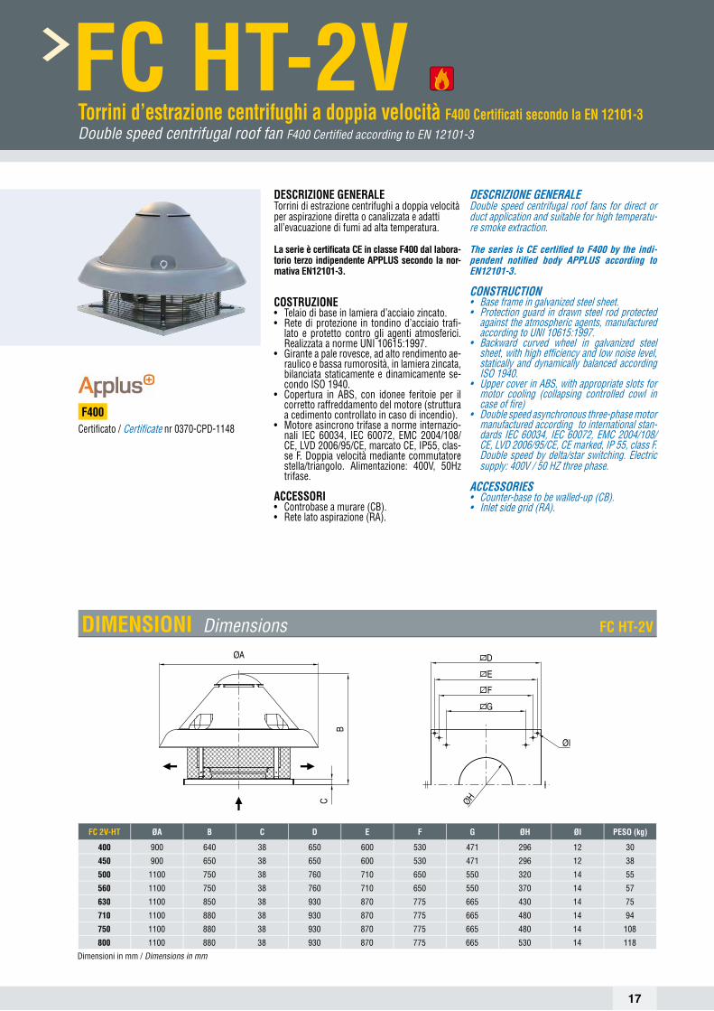
FC HT-2V Torrini d’estrazione centrifughi a doppia velocità F400 Certifi cati secondo la EN 12101-3DoublespeedcentrifugalrooffanF400CertifiedaccordingtoEN12101-3
DESCRIZIONE GENERALETorrini di estrazione centrifughi a doppia velocità per aspirazione diretta o canalizzata e adatti all’evacuazione di fumi ad alta temperatura.
La serie è certifi cata CE in classe F400 dal labora-torio terzo indipendente APPLUS secondo la nor-mativa EN12101-3.
COSTRUZIONE• Telaio di base in lamiera d’acciaio zincato.• Rete di protezione in tondino d’acciaio trafi -
lato e protetto contro gli agenti atmosferici. Realizzata a norme UNI 10615:1997.
• Girante a pale rovesce, ad alto rendimento ae-raulico e bassa rumorosità, in lamiera zincata, bilanciata staticamente e dinamicamente se-condo ISO 1940.
• Copertura in ABS, con idonee feritoie per il corretto raffreddamento del motore (struttura a cedimento controllato in caso di incendio).
• Motore asincrono trifase a norme internazio-nali IEC 60034, IEC 60072, EMC 2004/108/CE, LVD 2006/95/CE, marcato CE, IP55, clas-se F. Doppia velocità mediante commutatore stella/triangolo. Alimentazione: 400V, 50Hz trifase.
ACCESSORI• Controbase a murare (CB).• Rete lato aspirazione (RA).
DESCRIZIONE GENERALEDouble speed centrifugal roof fans for direct or duct application and suitable for high temperatu-re smoke extraction.
The series is CE certifi ed to F400 by the indi-pendent notifi ed body APPLUS according to EN12101-3.
CONSTRUCTION• Base frame in galvanized steel sheet.• Protection guard in drawn steel rod protected
against the atmospheric agents, manufactured according to UNI 10615:1997.
• Backward curved wheel in galvanized steel sheet, with high effi ciency and low noise level, statically and dynamically balanced according ISO 1940.
• Upper cover in ABS, with appropriate slots for motor cooling (collapsing controlled cowl in case of fi re)
• Double speed asynchronous three-phase motor manufactured according to international stan-dards IEC 60034, IEC 60072, EMC 2004/108/CE, LVD 2006/95/CE, CE marked, IP 55, class F. Double speed by delta/star switching. Electric supply: 400V / 50 HZ three phase.
ACCESSORIES• Counter-base to be walled-up (CB).• Inlet side grid (RA).
Certifi cato / Certifi cate nr 0370-CPD-1148F400
FC 2V-HT ØA B C D E F G ØH ØI PESO (kg)
400 900 640 38 650 600 530 471 296 12 30
450 900 650 38 650 600 530 471 296 12 38
500 1100 750 38 760 710 650 550 320 14 55
560 1100 750 38 760 710 650 550 370 14 57
630 1100 850 38 930 870 775 665 430 14 75
710 1100 880 38 930 870 775 665 480 14 94
750 1100 880 38 930 870 775 665 480 14 108
800 1100 880 38 930 870 775 665 530 14 118
Dimensioni in mm / Dimensionsinmm
B
C
ØA
ØI
ØH
DIMENSIONI Dimensions FC HT-2V

18
PRESTAZIONI Performance FC HT-2VFrequenza 50Hz – Temperatura dell’aria 15°C – Pressione barometrica 760 mm Hg – Peso specifico dell’aria 1,22 Kg/m3Frequency50Hz–Airtemperature15°C–Barometricpressure760mmHg–Airspecificweight1,22Kg/m3
Lp: livello di pressione sonora rilevato a 6 m - Lp:soundpressionlevelmeasuredat6m
FC HT-2V 45TipoType
ModelloModel U rpm Pm
(kW)In(A) IP/CL Mot.
(Gr)Lp
dB(A)
FC HT-2V 45 High T 1410 - Δ 0,75 2,20 55/F 80 53
FC HT-2V 45 Low T 910 - 0,75 1,30 55/F 80 44
FC HT-2V 50TipoType
ModelloModel U rpm Pm
(kW)In(A) IP/CL Mot.
(Gr)Lp
dB(A)
FC HT-2V 50 High T 1400 - Δ 1,10 2,80 55/F 90S 57
FC HT-2V 50 Low T 910 - 1,10 1,60 55/F 90S 47
FC HT-2V 40TipoType
ModelloModel U rpm Pm
(kW)In(A) IP/CL Mot.
(Gr)Lp
dB(A)
FC HT-2V 40 High T 1400 - Δ 0,55 1,06 55/F 80 49
FC HT-2V 40 Low T 910 - 0,55 0,90 55/F 80 39
FC HT-2V 56TipoType
ModelloModel U rpm Pm
(kW)In(A) IP/CL Mot.
(Gr)Lp
dB(A)
FC HT-2V 56 High T 910 - Δ 0,55 2,00 55/F 80 52
FC HT-2V 56 Low T 680 - 0,55 1,30 55/F 80 46

19
FC HT-2V 63TipoType
ModelloModel U rpm Pm
(kW)In(A) IP/CL Mot.
(Gr)Lp
dB(A)
FC HT-2V 63 High T 910 - Δ 1,10 3,40 55/F 90L 55
FC HT-2V 63 Low T 690 - 1,10 2,00 55/F 90L 49
FC HT-2V 71TipoType
ModelloModel U rpm Pm
(kW)In(A) IP/CL Mot.
(Gr)Lp
dB(A)
FC HT-2V 71 High T 930 - Δ 1,50 4,30 55/F 100L 57
FC HT-2V 71 Low T 700 - 1,50 2,50 55/F 100L 51
PRESTAZIONI Performance FC HT-2VFrequenza 50Hz – Temperatura dell’aria 15°C – Pressione barometrica 760 mm Hg – Peso specifico dell’aria 1,22 Kg/m3Frequency50Hz–Airtemperature15°C–Barometricpressure760mmHg–Airspecificweight1,22Kg/m3
Lp: livello di pressione sonora rilevato a 6 m - Lp:soundpressionlevelmeasuredat6m
FC HT-2V 75TipoType
ModelloModel U rpm Pm
(kW)In(A) IP/CL Mot.
(Gr)Lp
dB(A)
FC HT-2V 75 High T 940 - Δ 1,80 5,00 55/F 100L 61
FC HT-2V 75 Low T 700 - 1,80 2,90 55/F 100L 55
FC HT-2V 80TipoType
ModelloModel U rpm Pm
(kW)In(A) IP/CL Mot.
(Gr)Lp
dB(A)
FC HT-2V 80 High T 940 - Δ 3,00 7,00 55/F 112M 62
FC HT-2V 80 Low T 720 - 3,00 4,10 55/F 112M 56

20
TC HT Torrini d’estrazione centrifughi a scarico verticale F400 Certifi cati secondo la EN 12101-3CentrifugalrooffansverticaldischargeF400CertifiedaccordingtoEN12101-3
DESCRIZIONETorrini di estrazione centrifughi per aspirazione di-retta o canalizzata adatti all’evacuazione di fumi ad alta temperatura. La peculiarità della serie è data dal convogliatore a fl usso d’aria verticale che ga-rantisce una sicurezza ottimizzata in caso di incen-dio: l’estrazione rapida ed effi cace dei fumi tossici permette di proteggere al meglio le vie di fuga, di facilitare l’accesso alle squadre d’intervento, di fa-vorire l’incolumità delle persone e di minimizzare gli effetti dell’incendio sulle strutture dell’edifi cio.
La serie è idonea al funzionamento alla tempera-tura di +150°C ed è certifi cata CE in classe F400 secondo la Normativa EN12101-3 dall’ente certi-fi catore autonomo APPLUS.
COSTRUZIONE• Telaio di base in lamiera d’acciaio zincato e pro-
tetto contro gli agenti atmosferici con vernicia a polveri epossidiche.
• Rete di protezione in tondino d’acciaio trafi lato e protetto contro gli agenti atmosferici, realizzata a norme UNI 10615:1997.
• Girante a pale rovesce, ad alto rendimento ae-raulico e bassa rumorosità, in lamiera zincata, progettata per resistere ad alte temperature e per garantire il corretto raffreddamento del mo-tore in caso di emergenza (incendio). Bilancia-ta staticamente e dinamicamente secondo ISO 1940. Direttamente accoppiata al motore.
• Copertura e convogliatore in lamiera d’acciaio zincato e protetta contro gli agenti atmosferici con vernicia a polveri epossidiche grigio RAL 7001, con superfi cie goffrata e corrugata per accrescere la resistenza meccanica.
• Motore asincrono trifase a norme internazionali IEC 60034, IEC 60072, EMC 2004/108/CE, LVD 2006/95/CE, marcato CE, IP55, classe F.
ACCESSORI• Controbase a murare (CB)• Rete lato aspirazione (RA)
A RICHIESTA• Interruttore di servizio garantito per alte temperature• Scatola morsettiera garantita per alte temperature
DESCRIPTIONCentrifugal roof fans for direct or duct application suitable for high temperature smoke extraction.The peculiarity of the series is the vertical exhaust conveyor which guarantees an optimized safety in the event of a fi re: fast and effective toxic fume extraction, leading to saferescape routes, easier access for the emergency teams, promoting people safety and minimizing the effects of fi re on the building structures.
The series is suitable for running at the tempe-rature of +150°C and is CE certifi ed F400 accor-ding to EN12101-3. Certifi cation pending by the independent notifi ed body APPLUS.
CONSTRUCTION• Base frame in galvanized steel sheet protected
against atmospheric agents with epoxy fi nish. • Protection guard in drawn steel rod protected
against the atmospheric agents, manufactured according to UNI 10615:1997.
• Backward curved impeller in galvanized steel sheet, with high effi ciency and low noise level, designed to resist at high temperature and to ensure the proper cooling of the motor in case of emergency functioning. Statically and dyna-mically balanced according to ISO 1940. Direct-ly coupled to fl anged motor.
• Upper cover and vertical exhaust conveyor made in galvanized steel sheet protected against atmospheric agents with epoxy fi nish grey RAL 7001. Superfi cially embossed and corrugated to rise the mechanical resistance to the strain.
• Asynchronous three-phase motor or single-phase motor manufactured according to in-ternational standards IEC 600034, IEC 60072, EMC 2004/108/CE, LVD 2006/95/CE, CE mar-ked, IP 55, class F.
ACCESSORIES• Counter base to wall up (CB)• Inlet Protection Guard (RA)
UPON REQUEST• Service switch for high temperature• Terminal box for high temperature
F400
TIPO / TYPE AxA B C D E ØH Kg
TC HT 350 800 590 38 500 450 270 45
TC HT 400 950 640 38 650 600 296 65
TC HT 450 950 640 38 650 600 296 65
TC HT 500 1200 720 38 760 710 327 102
TC HT 560 1200 720 38 760 710 370 110
TC HT 630 1480 890 38 930 870 430 165
TC HT 710 1480 930 38 930 870 480 180
TC HT 750 1480 930 38 930 870 480 210
TC HT 800 1480 960 38 930 870 530 240
Dimensioni in mm / Dimensionsinmm
DIMENSIONI Dimensions TC HTAxA
0H
0I
B
C
DxD
ExE
AxA
0H
0I
B
C
DxD
ExE

21
PRESTAZIONI Performance TC HTFrequenza 50Hz – Temperatura dell’aria 15°C – Pressione barometrica 760 mm Hg – Peso specifico dell’aria 1,22 Kg/m3Frequency50Hz–Airtemperature15°C–Barometricpressure760mmHg–Airspecificweight1,22Kg/m3
Lp: livello di pressione sonora rilevato a 6 m - Lp:soundpressionlevelmeasuredat6m
TC HT 354TipoType
ModelloModel U P Pm
(kW)In(A) IP/CL Mot.
(Gr)Lp
dB(A)
TC HT 354 M 4 0,25 2,35 55/F 71 45
TC HT 354 T 4 0,25 0,86 55/F 71 49
TC HT 404TipoType
ModelloModel U P Pm
(kW)In(A) IP/CL Mot.
(Gr)Lp
dB(A)
TC HT 404 M 4 0,55 4,75 55/F 80 48
TC HT 404 T 4 0,55 1,60 55/F 80 51
TC HT 454 - 456TipoType
ModelloModel U P Pm
(kW)In(A) IP/CL Mot.
(Gr)Lp
dB(A)
TC HT 454 M 4 0,08 5,60 55/F 80 56
TC HT 454 T 4 0,75 2,20 55/F 80 55
TC HT 456 M 6 0,37 3,00 55/F 80 47
TC HT 456 T 6 0,37 1,20 55/F 80 39

22
PRESTAZIONI Performance TC HTFrequenza 50Hz – Temperatura dell’aria 15°C – Pressione barometrica 760 mm Hg – Peso specifico dell’aria 1,22 Kg/m3Frequency50Hz–Airtemperature15°C–Barometricpressure760mmHg–Airspecificweight1,22Kg/m3
Lp: livello di pressione sonora rilevato a 6 m - Lp:soundpressionlevelmeasuredat6m
TC HT 504 - 506TipoType
ModelloModel U P Pm
(kW)In(A) IP/CL Mot.
(Gr)Lp
dB(A)
TC HT 504 T 4 1,10 2,80 55/F 90 60
TC HT 506 T 6 0,37 1,20 55/F 80 49
TC HT 566TipoType
ModelloModel U P Pm
(kW)In(A) IP/CL Mot.
(Gr)Lp
dB(A)
TC HT 566 T 6 0,55 1,80 55/F 80 55
TC HT 636TipoType
ModelloModel U P Pm
(kW)In(A) IP/CL Mot.
(Gr)Lp
dB(A)
TC HT 636 T 6 1,10 3,40 55/F 90 59

23
PRESTAZIONI Performance TC HTFrequenza 50Hz – Temperatura dell’aria 15°C – Pressione barometrica 760 mm Hg – Peso specifico dell’aria 1,22 Kg/m3Frequency50Hz–Airtemperature15°C–Barometricpressure760mmHg–Airspecificweight1,22Kg/m3
Lp: livello di pressione sonora rilevato a 6 m - Lp:soundpressionlevelmeasuredat6m
TC HT 716TipoType
ModelloModel U P Pm
(kW)In(A) IP/CL Mot.
(Gr)Lp
dB(A)
TC HT 716 T 6 1,50 4,30 55/F 100 62
TC HT 756TipoType
ModelloModel U P Pm
(kW)In(A) IP/CL Mot.
(Gr)Lp
dB(A)
TC HT 756 T 6 2,20 5,00 55/F 112 65
TC HT 806TipoType
ModelloModel U P Pm
(kW)In(A) IP/CL Mot.
(Gr)Lp
dB(A)
TC HT 806 T 6 3,00 7,20 55/F 132 67

24
PR-Q HT-2V Ventilatori centrifughi pale rovesce doppia velocità F400 - Certifi cati secondo la EN 12101-3DoublespeedbackwardcurvedcentrifugalfansF400-CertifiedaccordingtoEN12101-3
DESCRIZIONE GENERALEVentilatori centrifughi a pale rovesce adatti all’eva-cuazione di fumi ad alta temperatura.La caratteristica peculiare della serie è data dal-la costruzione quadrangolare grazie alla quale è possibile ottenere quattro orientamenti (0°-90°-180°-270°) con lo stesso ventilatore e con un in-gombro limitatograzie all’eliminazione della sedia porta motore.La serie è idonea al funzionamento alla tem-peratura di +100°C ed è certifi cata CE in classe F400 dal laboratorio terzo indipendente Applus secondo la normativa EN 12101-3.
COSTRUZIONE• Cassa a spirale con fi ancate quadrangolari, re-
alizzata in lamiera d’acciaio zincato e protetta contro gli agenti atmosferici con vernicia a pol-veri epossidiche.
• Girante a semplice aspirazione, con pale ro-vesce curve ad alto rendimento aeraulico, re-alizzata in lamiera d’acciaio e mozzo in acciaio zincato elettroliticamente.
• Bocche premente e aspirante realizzate secon-do norma UNI EN ISO 13351
• Esecuzione 5 (accoppiamento diretto con giran-te a sbalzo su motore fl angiato), rotazione RD.
• Motore asincrono trifase a norme internazio-nali IEC 60034, IEC 60072, EMC 2004/108/CE, LVD 2006/95/CE, marcato CE, IP55, classe F. Doppia velocità mediante commutatore stella/ triangolo. Alimentazione: 400V, 50Hz trifase.
Accessori• Giunto antivibrante bocca aspirante e premente• Rete di protezione per bocche aspirante e pre-
mente realizzata a norma UNI 12499 e protetta contro gli agenti atmosferici.
• Contro fl angia bocca aspirante e premente• Supporti antivibranti• Regolatori di velocità ad autotrasformatore o
inverter
GENERAL DESCRIPTIONBackward curved centrifugal fans suitable for high temperature smoke extraction.The main characteristic of the PR-Q series is the quadrangular construction, which allows to obtain four orientations (0°-90°-180°-270°) with the same fan. The dimensions are reduced tank to the absen-ce of the motor support.The series is suitable for running at the tempe-rature of +100°C and CE certifi ed to F400 by the independent notifi ed body Applus according to EN 12101-3.
CONSTRUCTION• Volute casing with quadrangular frame, ma-
nufactured in galvanized steel sheet protected against atmospheric agents.
• Single inlet, backward curved wheel with high effi ciency, manufactured in galvanized steel sheet and steel hub.
• Inlet/outlet made according to UNI EN ISO 13351• Execution 5 (impeller directly coupled to fl an-
ged motor), rotation RD.• Double speed asynchronous three-phase motor
manufactured according to international stan-dards IEC 60034, IEC 60072, EMC 2004/108/ CE, LVD 2006/95/CE, CE marked, IP 55, classF. Double speed by delta/star switching. Electric supply: 400V / 50 Hz three phase.
Accessories• Inlet/outlet fl exible connectors• Inlet and outlet protection guard manufactured
according to UNI 12499 norm and protected against atmospheric agents.
• Inlet/outlet counterfl ange• Antivibration supports• Self transformer or inverters speed controllers
ORIENTAMENTI Dischargeangles PR-Q HT-2V
F400

25
PRESTAZIONI Performance PR-Q HT-2VFrequenza 50Hz – Temperatura dell’aria 15°C – Pressione barometrica 760 mm Hg – Peso specifico dell’aria 1,22 Kg/m3Frequency50Hz–Airtemperature15°C–Barometricpressure760mmHg–Airspecificweight1,22Kg/m3
Lp: livello di pressione sonora rilevato a 1,50 m - Lp:soundpressionlevelmeasuredat1,50m
Ht[Pa]
70
55
44
34
24
16
10
5.5
Ht[kgf/m2]
700
570 35 High
35 Low
450
350
260
185
120
70
34
0.740.540.40.290.210.150.110.080.05Q [m3/s]
3000220016001175850625450325225Q [m3/h]
Htot
1.150.80.550.350.250.150.10.05Q [m3/s]
40002850205014751050750525375250175Q [m3/h]
80
65
50
38
28
19
12
6.5
Ht[kgf/m2]
Ht[Pa]
800
660
530
410
310
220
150
90
46
Htot
40 High
40 Low
PR-Q HT-2V 35TipoType
ModelloModel U rpm Pm
(kW)In(A) IP/CL Mot.
(Gr)Lp
dB(A)
PR-Q HT-2V 35 High T 1350 - Δ 0,26 0,96 55/F 71 69
PR-Q HT-2V 35 Low T 980 - 0,26 0,55 55/F 71 59
PR-Q HT-2V 40TipoType
ModelloModel U rpm Pm
(kW)In(A) IP/CL Mot.
(Gr)Lp
dB(A)
PR-Q HT-2V 40 High T 1400 - Δ 0,55 1,06 55/F 80 70
PR-Q HT-2V 40 Low T 980 - 0,55 0,90 55/F 80 59
45003200225016001125800550375250175
Ht[Pa]
900
750
620
500
390
290
210
140
85
Q [m3/h]
1.30.90.60.40.250.150.10.05Q [m3/s]
90
75
60
48
36
26
18
11
Ht[kgf/m2] Htot
45 High
45 Low
800053003550235015501000650400250Q [m3/h]
21.30.850.550.350.20.10.05Q [m3/s]
120
95
75
55
40
28
18
10
Ht[kgf/m2]
Ht[Pa]
1200
990
800
630
480
350
240
150
80
Htot
50 High
50 Low
PR-Q HT-2V 45TipoType
ModelloModel U rpm Pm
(kW)In(A) IP/CL Mot.
(Gr)Lp
dB(A)
PR-Q HT-2V 45 High T 1400 - Δ 0,75 2,20 55/F 80 72
PR-Q HT-2V 45 Low T 980 - 0,75 1,30 55/F 80 61
PR-Q HT-2V 50TipoType
ModelloModel U rpm Pm
(kW)In(A) IP/CL Mot.
(Gr)Lp
dB(A)
PR-Q HT-2V 50 High T 1400 - Δ 1,10 2,80 55/F 90S 73
PR-Q HT-2V 50 Low T 980 - 1,10 1,60 55/F 90S 63

26
60
50
40
32
24
18
12
7.5
Ht[kgf/m2]
Ht[Pa]
600
500
410
330
250
185
130
85
50
Htot
1.350.90.60.40.250.150.10.05Q [m3/s]
60004100280019001300850550350200Q [m3/h]
56 High
56 Low
106.54.252.751.81.150.750.450.25
Ht[Pa]
800
670
550
440
340
250
180
120
70
Q [m3/h] x 1000
2.61.71.10.70.450.250.150.05Q [m3/s]
80
65
50
40
30
22
15
9.5
Ht[kgf/m2]
Htot
63 High
63 Low
PRESTAZIONI Performance PR-Q HT-2VFrequenza 50Hz – Temperatura dell’aria 15°C – Pressione barometrica 760 mm Hg – Peso specifico dell’aria 1,22 Kg/m3Frequency50Hz–Airtemperature15°C–Barometricpressure760mmHg–Airspecificweight1,22Kg/m3
Lp: livello di pressione sonora rilevato a 1,50 m - Lp:soundpressionlevelmeasuredat1,50m
PR-Q HT-2V 56TipoType
ModelloModel U rpm Pm
(kW)In(A) IP/CL Mot.
(Gr)Lp
dB(A)
PR-Q HT-2V 56 High T 900 - Δ 0,55 2,00 55/F 80 70
PR-Q HT-2V 56 Low T 730 - 0,55 1,30 55/F 80 64
PR-Q HT-2V 63TipoType
ModelloModel U rpm Pm
(kW)In(A) IP/CL Mot.
(Gr)Lp
dB(A)
PR-Q HT-2V 63 High T 1400 - Δ 1,10 3,40 55/F 90L 73
PR-Q HT-2V 63 Low T 980 - 1,10 2,00 55/F 90L 65

27
DIMENSIONI Dimensions PR-Q HT-2V
TIPO / TYPE A A1 B B1 C D E F G H H1ASPIRANTE / INLET
kgI L M N
PR-Q HT 350 620 520 650 55 295 325 370 280 177 270 450 270 450 8 M8 35
PR-Q HT 400 680 580 790 690 305 375 440 350 277 320 520 296 500 8 M8 45
PR-Q HT 450 740 640 880 780 305 435 490 390 255 320 520 296 500 8 M8 50
PR-Q HT 500 820 660 960 800 340 480 540 420 265 400 620 327 560 12 M8 75
PR-Q HT 560 890 730 1040 880 370 520 600 440 300 400 585 370 620 12 M8 80
PR-Q HT 630 910 750 1100 940 410 500 650 450 320 455 675 430 690 12 M8 100
Dimensioni in mm / Dimensionsinmm
TIPO / TYPEPREMENTE / OUTLET
a b n1 x c d n2 x e f g h l m
PR-Q HT 350 315 200 2 x 125 353 1 x 100 238 385 270 14 10
PR-Q HT 400 355 250 2 x 125 393 1 x 125 288 425 320 14 10
PR-Q HT 450 400 250 2 x 125 438 1 x 125 288 470 320 14 10
PR-Q HT 500 450 300 3 x 125 514 2 x 125 364 550 400 18 12
PR-Q HT 560 500 300 3 x 125 564 2 x 125 364 600 400 18 12
PR-Q HT 630 560 355 4 x 125 624 2 x 125 419 660 455 20 12
Dimensioni in mm / Dimensionsinmm

28
BOX-T HT Ventilatori cassonati a doppia aspirazione a trasmissione F400 Certifi cati secondo la EN 12101-3BeltdrivendoubleinletboxfansF400CertifiedaccordingtoEN12101-3
DESCRIZIONE GENERALEI ventilatori della serie BOX-T HT a doppia aspira-zione a trasmissione sono dei centrifughi casso-nati nati per utilizzo industriale dove è necessaria l’estrazione dei fumi di incendio. Vengono impie-gati per gli impianti di aspirazione dove esistono problemi di fumane e temperature fi no a 200°C con servizio continuo o nei casi di incendio dove si richiede 400°C per 2 ore consecutive.La serie è idonea al funzionamento alla tem-peratura di +200°C ed è certifi cata CE in Classe F400 secondo la EN12101-3 dall’ente autonomo qualifi cato Applus.
COSTRUZIONE• Cassone smontabile a forma cubica in lamiera
di acciaio zincata• Ventilatore a doppia aspirazione con girante
centrifuga a pale avanti.• Trasmissione con supporti auto allineanti ester-
na al fl usso. Protetta da un carter in lamiera.• Piastra portamotore regolabile in altezza per un
ottimale tensionamento delle cinghie, con pos-sibilità di posizionare la trasmissione e il moto-re a destra o a sinistra guardando la bocca di espulsione secondo le esigenze dell’impianto.
• Motore asincrono trifase, IP 55, Classe F, sin-gola o doppia polarità, idoneo a servizio S1, forma B3, costruzione a norme UNEL MEC.
• Esecuzione 9: accoppiamento a trasmissione con motore posizionato sul pannello superiore.
• Esecuzione 12: accoppiamento a trasmissio-ne con motore posizionato lateralmente su un basamento comune (solo per motori sopra i 7,5kW).
A RICHIESTA• Versione con motore a doppia polarità
DESCRIPTIONThe belt driven double inlet BOX-T HT fans are de-stined to plants requiring fi re smoke exhaust. They are suitable for conveying clean air and non dusty smokes up to the maximum temperature of 200°C in continuous service or in case of fi re emergency at the temperature of 400°C for 120 minutes (F400).The series is suitable for running at the tempera-ture of +200°C and CE certifi ed F400 according to EN12101-3 by the independent notify body Applus.
CONSTRUCTION• Dismountable cabinet in galvanized steel sheet.
Double inlet impeller with forward curved blades in galvanized steel sheet.
• Belt coupling with self aligning supports, outside the airfl ow. Height adjustable motor support pla-te for the tensioning of the belt. Belt coupling is protected by a guard in galvanized sheet.
• Asynchronous three-phase motor, IP 55 mecha-nical protection, insulation class F, single or dou-ble polarity, suitable for S1 service, mounting type B3, construction according to IEC/EEC (UNEL MEC).
• Arrangement 9: belt coupling with motor placed on the upper panel.
• Arrangement 12: belt coupling with motor placed aside on a common basement (only for motors above 7.5kW).
UPON REQUEST• Version with double polarity motor.
F400
DIMENSIONI Dimensions BOX-T HT
TIPO / TYPE A B H C D E ØF G I L M QKg
min max
BOX-T HT 250 650 600 600 300 300 158 405 100 370 230 300 350 75-90BOX-T HT 300 730 700 680 350 350 173 500 100 425 255 340 410 100-135BOX-T HT 350 860 800 750 400 400 173 610 100 470 280 375 410 145-270BOX-T HT 400 1030 900 840 450 450 173 650 100 535 305 420 420 210-330BOX-T HT 450 1200 1000 960 500 500 173 750 100 630 330 480 420 250-500BOX-T HT 500 1250 1200 1020 600 600 173 800 100 640 380 510 420 310-590
Dimensioni in mm / Dimensionsinmm

29
BOX-T HT 254TipoType
ModelloModel U rpm Pm
(kW)In(A) m3/h IP/CL Mot.
(Gr)Lp
dB(A)
BOX-T HT 254/A T 1800 2,20 4,90 5.700 55/F 100 66
BOX-T HT 254/B T 1600 1,50 3,45 5.050 55/F 90 64
BOX-T HT 254/C T 1400 1,10 2,64 4.300 55/F 90 61
BOX-T HT 254/D T 1200 0,75 1,93 3.700 55/F 80 57
BOX-T HT 254/E T 1000 0,37 1,11 3.150 55/F 71 53
BOX-T HT 304TipoType
ModelloModel U rpm Pm
(kW)In(A) m3/h IP/CL Mot.
(Gr)Lp
dB(A)
BOX-T HT 304/A T 1800 5,50 11,00 9.700 55/F 132 72
BOX-T HT 304/B T 1600 4,00 8,26 8.700 55/F 112 69
BOX-T HT 304/C T 1400 3,00 6,47 7.400 55/F 100 67
BOX-T HT 304/D T 1200 2,20 4,90 6.300 55/F 100 63
BOX-T HT 304/E T 1000 1,10 2,64 5.300 55/F 90 59
PRESTAZIONI Performance BOX-T HTFrequenza 50Hz – Temperatura dell’aria 15°C – Pressione barometrica 760 mm Hg – Peso specifico dell’aria 1,22 Kg/m3Frequency50Hz–Airtemperature15°C–Barometricpressure760mmHg–Airspecificweight1,22Kg/m3
Lp: livello di pressione sonora rilevato a 1,50 m - Lp:soundpressionlevelmeasuredat1,50m

30
PRESTAZIONI Performance BOX-T HTFrequenza 50Hz – Temperatura dell’aria 15°C – Pressione barometrica 760 mm Hg – Peso specifico dell’aria 1,22 Kg/m3Frequency50Hz–Airtemperature15°C–Barometricpressure760mmHg–Airspecificweight1,22Kg/m3
Lp: livello di pressione sonora rilevato a 1,50 m - Lp:soundpressionlevelmeasuredat1,50m
BOX-T HT 354TipoType
ModelloModel U rpm Pm
(kW)In(A) m3/h IP/CL Mot.
(Gr)Lp
dB(A)
BOX-T HT 354/A T 1600 11,00 21,30 13.600 55/F 160 74
BOX-T HT 354/B T 1400 5,50 11,00 12.000 55/F 132 71
BOX-T HT 354/C T 1200 4,00 8,26 10.100 55/F 112 68
BOX-T HT 354/D T 1000 2,20 4,90 8.250 55/F 100 64
BOX-T HT 354/E T 800 1,10 2,64 6.800 55/F 90 59
BOX-T HT 404TipoType
ModelloModel U rpm Pm
(kW)In(A) m3/h IP/CL Mot.
(Gr)Lp
dB(A)
BOX-T HT 404/A T 1400 11,00 21,30 18.200 55/F 160 74
BOX-T HT 404/B T 1200 7,50 14,60 16.000 55/F 132 72
BOX-T HT 404/C T 1000 4,00 8,26 13.000 55/F 112 68
BOX-T HT 404/D T 800 2,20 4,90 10.100 55/F 100 63

31
PRESTAZIONI Performance BOX-T HTFrequenza 50Hz – Temperatura dell’aria 15°C – Pressione barometrica 760 mm Hg – Peso specifico dell’aria 1,22 Kg/m3Frequency50Hz–Airtemperature15°C–Barometricpressure760mmHg–Airspecificweight1,22Kg/m3
Lp: livello di pressione sonora rilevato a 1,50 m - Lp:soundpressionlevelmeasuredat1,50m
BOX-T HT 454TipoType
ModelloModel U rpm Pm
(kW)In(A) m3/h IP/CL Mot.
(Gr)Lp
dB(A)
BOX-T HT 454/A T 1400 22,00 38,80 25.500 55/F 180 74
BOX-T HT 454/B T 1200 15,00 27,70 22.000 55/F 160 72
BOX-T HT 454/C T 1000 7,50 14,60 18.000 55/F 132 68
BOX-T HT 454/D T 800 4,00 8,26 14.500 55/F 112 63
BOX-T HT 454/E T 600 1,50 3,45 11.000 55/F 90 60
BOX-T HT 504TipoType
ModelloModel U rpm Pm
(kW)In(A) m3/h IP/CL Mot.
(Gr)Lp
dB(A)
BOX-T HT 504/A T 1400 30,00 53,00 35.000 55/F 225 82
BOX-T HT 504/B T 1200 22,00 38,80 30.000 55/F 180 78
BOX-T HT 504/C T 1000 15,00 27,70 25.000 55/F 160 74
BOX-T HT 504/D T 800 7,50 14,60 20.000 55/F 132 70
BOX-T HT 504/E T 600 3,00 6,47 15.000 55/F 100 64
32
TIPOTYPE A A1 ØB ØC ØD E ØF kg
CCpro 40 200 430 400 450 496 8 12 6
CCpro 45 200 430 450 500 546 8 12 7
CCpro 50 200 450 500 560 598 12 12 8
CCpro 56 200 450 560 620 658 12 12 9
CCpro 63 240 490 630 690 730 12 12 11
CCpro 71 280 530 710 770 810 16 12 13
CCpro 80 240 590 800 860 910 16 12 20
CCpro 90 340 690 900 970 1030 16 16 31
CCpro 100 410 760 1000 1070 1130 16 16 39
CCpro 112 410 760 1120 1190 1250 20 16 58
CCpro 125 410 760 1250 1320 1380 20 16 65
CCpro 140 510 960 1415 1470 1540 20 16 88
CCpro 160 510 960 1615 1680 1730 24 18 98
Dimensioni in mm / Dimensionsinmm
TIPOTYPE A ØB ØC ØD E ØF kg
CCga 40 200 400 450 496 8 12 7
CCga 45 200 450 500 546 8 12 8
CCga 50 200 500 560 598 12 12 9
CCga 56 200 560 620 658 12 12 10
CCga 63 200 630 690 730 12 12 11
CCga 71 200 710 770 810 16 12 13
CCga 80 200 800 860 910 16 12 21
CCga 90 200 900 970 1030 16 16 23
CCga 100 200 1000 1070 1130 16 16 26
CCga 112 200 1120 1190 1250 20 16 29
CCga 125 200 1250 1320 1380 20 16 32
CCga 140 200 1415 1470 1540 20 16 38
CCga 160 200 1615 1680 1730 24 18 44
Dimensioni in mm / Dimensionsinmm
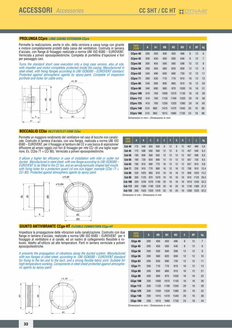
PROLUNGA CCpro LONg CASINg ExTENSION CCpro
Permette la realizzazione, anche in sito, della versione a cassa lunga con girante e motore completamente protetti dalla cassa del ventilatore. Costruita in lamiera d’acciaio, con flange di fissaggio realizzate a norma UNI ISO 6580 – EUROVENT. Verniciata a polveri epossipoliestiriche. Completa di portellina d’ispezione e fori per passaggio cavi.
Turns the standard short case execution into a long case version, also at site, with impeller and motor completely protected inside the casing. Manufactured in steel sheet, with fixing flanges according to UNI ISO6580 – EUROVENT standard. Protected against atmospheric agents by epoxy-paint. Complete of inspection porthole and holes for cable entry.
BOCCAGLIO CCbo INLET/OUTLET CONE CCbo
Permette un maggiore rendimento del ventilatore nel caso di bocche non canaliz-zate. Costruito in lamiera d’acciaio, con una flangia, realizzata a norma UNI ISO 6580 – EUROVENT, per il fissaggio al tamburo del CC e una bocca di aspirazione/diffusione ad ampio raggio con fori di fissaggio per rete CCr (di una taglia supe-riore, Es. CCbo 71 + CCr 80). Verniciato a polveri epossipoliestiriche.
It allows a higher fan efficiency in case of installation with inlet or outlet not ducted. Manufactured in steel sheet, with one flange according to UNI ISO6580 – EUROVENT to be fitted to the CC fan, and an aerodynamically shaped bell mouth, with fixing holes for a protection guard (of one size bigger, example CCbo 71 + CCr 80). Protected against atmospheric agents by epoxy paint.
GIUNTO ANTIVIBRANTE CCga-HT FLExIbLE CONNECTORS CCga-HT
Impedisce la propagazione delle vibrazioni sulla canalizzazione. Costruito con due flange in lamiera d’acciaio, realizzate a norma UNI ISO 6580 – EUROVENT per il fissaggio al ventilatore e al canale, ed un nastro di collegamento flessibile e ro-busto. Adatto all’utilizzo ad alte temperature. Parti in lamiera verniciate a polveri epossipoliestiriche.
It prevents the propagation of vibrations along the ducted system. Manufactured with two flanges in steel sheet, according to UNI ISO6580 – EUROVENT standard for fixing to the fan and to the duct, and a strong flexible fabric joint. Suitable for high temperature working. Components in steel sheet protected against atmosphe-ric agents by epoxy paint.
TIPOTYPE A B C D E F G H I L kg
Ccb 40 175 546 450 500 8 12 8 12 407 496 5,6
Ccb 45 175 598 500 560 12 12 8 12 457 546 6,3
Ccb 50 190 658 560 620 12 12 12 12 507 598 8,5
Ccb 56 190 730 620 690 12 12 12 12 567 730 8,5
Ccb 63 190 810 690 770 16 12 12 12 637 810 9,8
Ccb 71 230 910 770 860 16 12 16 12 708 910 12,4
Ccb 80 250 1025 860 970 16 16 16 12 808 1025 15,2
Ccb 90 300 1125 970 1070 16 16 16 16 910 1125 29,4
Ccb 100 300 1245 1070 1190 20 16 16 16 1010 1245 33,3
Ccb 112 300 1380 1190 1320 20 16 20 16 1130 1380 37,3
Ccb 125 300 1525 1320 1470 20 16 20 16 1260 1525 42,5
Dimensioni in mm / Dimensionsinmm
ØD
ØC
n°G ØH
n°E ØF
ØBØL ØI
A
ACCESSORI Accessories CC SHT / CC HT

33
TIPOTYPE ØA kg
CCr 40 450 0,8
CCr 45 500 1,0
CCr 50 560 1,3
CCr 56 620 1,6
CCr 63 690 1,9
CCr 71 770 2,2
CCr 80 860 3,0
CCr 90 970 3,4
CCr 100 1070 3,5
CCr 112 1190 4,0
CCr 125 1320 4,5
CCr 140 1470 6,5
CCr 160 1680 8,5
TIPOTYPE A B C D ØE kg
CCst 40 400 300 320 2 10 1
CCst 45 450 350 350 2 10 1,5
CCst 50 500 400 380 2 10 2
CCst 56 560 460 410 2 10 2,5
CCst 63 630 480 450 2 10 2,8
CCst 71 710 550 490 2 10 3
CCst 80 800 660 540 3 14 3,8
CCst 90 900 760 600 3 14 4,5
CCst 100 1000 860 640 3 14 4,8
CCst 112 1120 980 710 3 14 6,8
CCst 125 1250 950 770 3 14 7,8
CCst 140 1400 1100 850 3 14 11
CCst 160 1600 1300 960 3 16 21,5
Dimensioni in mm / Dimensionsinmm
TIPOTYPE ØA ØB C ØD kg
CCf 40 400 450 8 12 1,7
CCf 45 450 500 8 12 1,9
CCf 50 500 560 12 12 2,1
CCf 56 560 620 12 12 2,4
CCf 63 630 690 12 12 2,7
CCf 71 710 770 16 12 3,3
CCf 80 800 860 16 12 3,7
CCf 90 900 970 16 16 4,7
CCf 100 1000 1070 16 16 5,2
CCf 112 1120 1190 20 16 6,5
CCf 125 1250 1320 20 16 8
CCf 140 1415 1470 20 16 10
CCf 160 1615 1680 24 18 12
Dimensioni in mm / Dimensionsinmm
RETI PROTEZIONE CCr PROTECTION gUARDS CCr
Salvaguardano dal contatto accidentale con le parti in movimento del ventilatore.Realizzate in filo d’acciaio, a norma UNI 10615 e protette contro gli agenti atmosferici.CCr: versione piana (per cassa lunga e cassa corta lato girante),
They prevent from casual contact with moving parts of the fan. Manufactured in steel rod according to UNI 10615 standard and protected against atmospheric agents.CCr: flat version (for long case and short case on impeller side)
STAFFE DI SOSTEGNO CCst SUPPORT FEET CCst
Consentono l’ancoraggio del ventilatore a pavimento o soffitto. Realizzate in lamie-ra d’acciaio e verniciate a polveri epossipoliestiriche.
Suitable to fasten the fan on the floor or to the ceiling. Manufactured in steel sheet and protected against atmospheric agents by epoxy paint.
CONTROFLANGIA CCf COUNTER FLANgE CCf
Piastra a forma di anello provvista di fori a norma UNI ISO 6580 – EUROVENT. Viene utilizzata per facilitare il collegamento tra il canale ed il ventilatore.
Ring plate with holes according to UNI ISO6580 – EUROVENT standard, compati-ble with fan flange. It is used for easier connection between the CC fan and the duct.
ACCESSORI Accessories CC SHT / CC HT

34
TIPOTYPE ØA ØB C ØD kg
CCfc 40 400 450 8 12 1,7
CCfc 45 450 500 8 12 2
CCfc 50 500 560 12 12 2,2
CCfc 56 560 620 12 12 2,5
CCfc 63 630 690 12 12 2,9
CCfc 71 710 770 16 12 3,3
CCfc 80 800 860 16 12 3,8
CCfc 90 900 970 16 16 4,2
CCfc 100 1000 1070 16 16 5
CCfc 112 1120 1190 20 16 5,8
CCfc 125 1250 1320 20 16 6,5
CCfc 140 1415 1470 20 16 10
CCfc 160 1615 1680 24 18 12
Dimensioni in mm / Dimensionsinmm
TIPO / TYPECCsa / CCsb ØB Øb ØC D ØE ØF
40 540 400 450 8 M10 19545 610 450 500 8 M10 19550 660 500 560 12 M10 25056 720 560 620 12 M10 25063 790 630 690 12 M10 30071 870 710 770 16 M10 38080 1000 800 860 16 M10 38090 1100 900 970 16 M12 380100 1200 1000 1070 16 M12 655112 1320 1120 1190 20 M12 655125 1450 1250 1320 20 M12 655
Dimensioni in mm / Dimensionsinmm
TIPO / TYPECCsa A 1Ø kg A 1,5Ø kg A 2Ø kg
40 400 12 600 17 800 2145 450 15 675 20 900 2450 500 18 750 25 1000 3256 560 21 840 28 1120 3563 630 24 945 33 1260 4371 710 35 1065 49 1420 6380 800 43 1200 61 1600 7990 900 70 1350 94 1800 112100 1000 113 1500 137 2000 161112 1120 130 1680 154 2240 178125 1250 152 1875 185 2500 213
Dimensioni in mm / Dimensionsinmm
TIPO / TYPECCsb A 1Ø kg A 1,5Ø kg A 2Ø kg
40 400 14 600 21 800 2645 450 17 675 24 900 2950 500 23 750 32 1000 3956 560 28 840 37 1120 4463 630 32 945 44 1260 5571 710 44 1065 62 1420 7880 800 56 1200 79 1600 10190 900 130 1350 153 1800 175100 1000 143 1500 180 2000 216112 1120 165 1680 202 2240 238125 1250 193 1875 240 2500 282
Dimensioni in mm / Dimensionsinmm
CONTROFLANGIA CON COLLARE CCfc COUNTER FLANgE wITH COLLAR CCfc
Controflangia a forma di anello con collare, provvista di fori a norma UNI ISO 6580 – EUROVENT. Viene utilizzata per facilitare il collegamento tra il canale ed il ventilatore.
Counter flange with addition of 80 mm of round duct. It is used for easier connec-tion between the CC fan and the duct.
SILENZIATORI CILINDRICI CCsa/CCsb CYLINDRICAL SILENCERS CCsa/CCsb
I silenziatori cilindrici CCs sono disponibili in due versioni, senza ogiva (CCsa) e con ogiva (CCsb). La presenza dell’ogiva permette una maggiore attenuazione della rumorosità ma genera una perdita di carico aggiuntiva nell’impianto. Entrambe le versioni possono essere fissate alla flangia del CC corrispondente sia in aspirazio-ne sia in mandata. La serie CCsa, non genere perdite di carico aggiuntive. La serie CCsb, comporta una perdita di carico nella misura evidenziata nel diagramma di pagina **. E’ possibile fornire i silenziatori in versione di lunghezza pari a 1 - 1,5 - 2 volte il diametro (b). Questi silenziatori sono costruiti completamente in lamiera zincata, la parte interna e l’ogiva in lamiera forata al fine di permettere, efficace-mente, l’azione del materassino fonoassorbente in lana minerale. La temperatura d’esercizio è compresa fra –40 e +150°C.
The cylindrical silencers CCs are available in two versions, without pod (CCsa) and with pod (CCsb). The presence of the pod allows a higher noise attenuation, but creates an additional pressure drop in the system. Both the versions can be fixed to the corresponding flange of the CC in inlet and outlet. The CCsa series doesn’t create additional losses. The CCsb series gives an additional loss, as shown in the diagram at page **. Silencers can be provided with length equal to 1 - 1,5 - 2 times the diameter (b). These silencers are manufactured completely in galvanized steel. The internal part and the pod are made in perforated sheet, to effectively allow the sound absorption of the acoustic lining in mineral wool. The working temperature is included from -40°C and +150°C.
ACCESSORI Accessories CC SHT / CC HT

35
ACCESSORI Accessories CC SHT / CC HT
KIT TAV-HT - Convogliatore verticale per ventilatori assiali intubati (installabile a tetto)KIT TAV-HT - ROOF TERMINAL FOR DUCT AxIAL FANS
Convogliatore esterno per espulsione verticale costituito da una base in lamiera verniciata con vernici a polveri epossipoliestiriche e pannelli verticali in lamiera zincata.
Comprende:• Serranda automatica con alette in alluminio a doppio battente, rivestite
di materiale fonoassorbente.• Piastra di appoggio in lamiera verniciata con vernici a polveri
epossipoliestiriche.• Rete di protezione sulla mandata realizzata a norme UNI 9219 – DIN
31001 e protetta contro gli agenti atmosferici.
Outer conveyor for vertical exhaust with epoxy painted steel sheet base and with vertical panels in galvanized steel sheet.The kit includes:• Double wing aluminium gravity shutters, acoustically lined.• Support plate in epoxy painted steel sheet.• Weatherproof outlet protection guard according to norm UNI 10615
B
A I
C TIPOTYPE A B C I PESO/wEIgHT
(Kg)
TAV-HT 800 1280 750 1250 50 80
TAV-HT 900 1280 750 1250 50 80
TAV-HT 1000 1580 600 1500 60 100
TAV-HT 1120 1580 600 1500 60 100
TAV-HT 1250 1840 685 1800 85 120
TAV-HT 1400 1840 685 1800 85 120
Dimensioni in mm / Dimensionsinmm
ACCESSORI Accessories FC HT-2V / TC HT
COUNTER BASES TO BE WALLED UP (CB)the counter base ensures an effective an-chorage to the concrete support, through the fi xing of four metal strips suitably designed. It is made in solid steel with arrangement for fi xing to the fan base.
CONTROBASI A MURARE (CB)La controbase garantisce un effi cace ancoraggio al cavedio, tramite la muratura delle quattro zanche appositamente realizzate. Manufatto realizzato in robusta lamiera con predisposto il fi ssaggio alla base del torrino.

36
ACCESSORI Accessories PR-Q HT-2V
CONTROFLANGIA PREMENTE / OUTLET CONNECTOR FLANgE
GIUNTO ANTIVIBRANTE PREMENTE / OUTLET gUARD
RETE PROTEZIONE BOCCA PREMENTE / OUTLET PROTECTION gUARD
TIPOTYPE A B n1xC D n2xE F G H L M Kg
35 315 200 2x125 353 1x100 238 385 270 14 10 3,5
40 355 250 2x125 393 1x125 288 425 320 14 10 4
45 400 250 2x125 438 1x125 288 470 320 14 10 4,5
50 450 300 3x125 514 2x125 364 550 400 18 12 5
56 500 300 3x125 564 2x125 364 600 400 18 12 5,5
63 560 355 4x125 624 2x125 419 660 455 20 12 6
Dimensioni in mm / Dimensionsinmm
TIPOTYPE A B n1xC D n2xE F L M Sp. Kg
35 385 270 2x125 353 1x100 238 14 10 15/10 0,49
40 425 320 2x125 393 1x125 288 14 10 15/10 0,58
45 470 320 2x125 438 1x125 288 14 10 15/10 0,61
50 550 400 3x125 514 2x125 364 18 12 20/10 1,33
56 600 400 3x125 564 2x125 364 18 12 20/10 1,41
63 660 455 4x125 624 2x125 419 20 12 20/10 1,59
Dimensioni in mm / Dimensionsinmm
TIPOTYPE A B n1xC D n2xE F G H L M Sp. Kg
35 315 200 2x125 353 1x100 238 385 270 14 10 15/10 0,47
40 355 250 2x125 393 1x125 288 425 320 14 10 15/10 0,55
45 400 250 2x125 438 1x125 288 470 320 14 10 15/10 0,58
50 450 300 3x125 514 2x125 364 550 400 18 12 20/10 1,30
56 500 300 3x125 564 2x125 364 600 400 18 12 20/10 1,38
63 560 355 4x125 624 2x125 419 660 455 20 12 20/10 1,56
Dimensioni in mm / Dimensionsinmm

37
ACCESSORI Accessories PR-Q HT-2V
GIUNTO ANTIVIBRANTE CCga-HT / FLExIbLE CONNECTORS CCga-HT
RETE PROTEZIONE BOCCA ASPIRANTE CCr / INLET PROTECTION gUARD CCr
CONTROFLANGIA CCf / COUNTER FLANgE CCf
TIPOTYPE
ModelloModel A ØB ØC ØD E ØF kg
CCga 40 PR-Q 35 200 400 450 496 8 12 7
CCga 45 PR-Q 40-45 200 450 500 546 8 12 8
CCga 50 PR-Q 50 200 500 560 598 12 12 9
CCga 56 PR-Q 56 200 560 620 658 12 12 10
CCga 63 PR-Q 63 200 630 690 730 12 12 11
Dimensioni in mm / Dimensionsinmm
Impedisce la propagazione delle vibrazioni sulla canalizzazione. Costruito con due flange in lamiera d’acciaio, realizzate a norma UNI ISO 6580 – EUROVENT per il fissaggio al ventilatore e al canale, ed un nastro di collegamento flessibi-le e robusto. Adatto all’utilizzo ad alte temperature. Parti in lamiera verniciate a polveri epossipoliestiriche.
It prevents the propagation of vibrations along the ducted system. Manufactu-red with two flanges in steel sheet, according to UNI ISO6580 – EUROVENT standard for fixing to the fan and to the duct, and a strong flexible fabric joint. Suitable for high temperature working. Components in steel sheet protected against atmospheric agents by epoxy paint.
TIPOTYPE
ModelloModel ØA kg
CCr 40 PR-Q 35 450 0,8
CCr 45 PR-Q 40-45 500 1,0
CCr 50 PR-Q 50 560 1,3
CCr 56 PR-Q 56 620 1,6
CCr 63 PR-Q 63 690 1,9
Salvaguardano dal contatto accidentale con le parti in movimento del ventilatore.Realizzate in filo d’acciaio, a norma UNI 10615 e protette contro gli agenti atmosferici.CCr: versione piana (per cassa lunga e cassa corta lato girante),
They prevent from casual contact with moving parts of the fan. Manufactured in steel rod according to UNI 10615 standard and protected against atmospheric agents.CCr: flat version (for long case and short case on impeller side)
TIPOTYPE
ModelloModel ØA ØB C ØD kg
CCf 40 PR-Q 35 400 450 8 12 1,7
CCf 45 PR-Q 40-45 450 500 8 12 1,9
CCf 50 PR-Q 50 500 560 12 12 2,1
CCf 56 PR-Q 56 560 620 12 12 2,4
CCf 63 PR-Q 63 630 690 12 12 2,7
Dimensioni in mm / Dimensionsinmm
Piastra a forma di anello provvista di fori a norma UNI ISO 6580 – EUROVENT. Viene utilizzata per facilitare il collegamento tra il canale ed il ventilatore.
Ring plate with holes according to UNI ISO6580 – EUROVENT standard, compati-ble with fan flange. It is used for easier connection between the CC fan and the duct.

GUIDA ALLA VENTILAZIONE DI AUTORIMESSEGuidelinestocarparkventilation

39
Ventilazione di Autorimesse: Principi & SoluzioniCarParkVentilation:Principles&Solutions
PRINCIPIO GENERALEVentilare le autorimesse chiuse o sotterranee risponde a due esigenze fondamentali: rimuovere le sostanze inquinanti emesse dagli autoveicoli e, in caso d’incendio, mantenere sotto controllo i fumi e i gas caldi che si sprigionano, proteggendo le vie di fuga e facilitando l’accesso alle squa-dre di intervento.
TECNOLOGIA SPECIFICANegli ultimi anni, la tecnologia dei ventilatori a getto e a induzione si è imposta come nuovo standard per la ventilazione normale e antincendio delle autorimesse.Essa rappresenta infatti l’alternativa più innovativa ed economica ai tradi-zionali sistemi di evacuazione meccanica in condotti. L’accurata gestione del progetto in tutte le sue fasi di sviluppo, che prevede il fondamentale ausilio di programmi di calcolo fl uido-dinamici, è inoltre garanzia di effetti-va funzionalità del sistema.
BASIC PRINCIPLEThe ventilation of enclosed or underground car parks fulfi ls two key re-quirements: remove the pollutants emitted by cars and, in the event of a fi re, control the hot fumes and gases produced by the fi re, protecting the escape routes and easing access for the emergency teams.
SPECIAL TECHNOLOGYIn recent years, the jet or induction fans technology has been established as the new standard for normal ventilation and smoke extraction in case of fi re in enclosed car parks..In fact, this technology represents the most innovative and cost-effec-tive alternative to traditional ducted mechanical extraction systems. Carefully managing the project in all its development stages, which re-quires the fundamental use of fl uid dynamics calculation programs, also ensures that the system is working correctly.
Il sistema di ventilazione per autorimesse provvede alla rimozione completa dell’aria inquinata nei parcheggi sotterranei e/o all’estrazione dei fumi in caso di incendio. Su richiesta, può anche essere progettato combinando i due requisiti di ventilazione normale e antincendio: in questo caso specifi co si parla di sistema dual purpose.
Car park ventilationsystem provides either normal ventilation and can also be provided for smoke extract in case of fi re in underground car parks, or a combination of both, i.e. a dual purpose fan.
CC-JD HTJET FAN Ventilatori assialiad impulso per autorimesseJET FAN Impulse fans forcar park ventilation
CC-JC HTVentilatori centrifughi ad induzione per autorimesseCentrifugal induction fans for car park ventilation
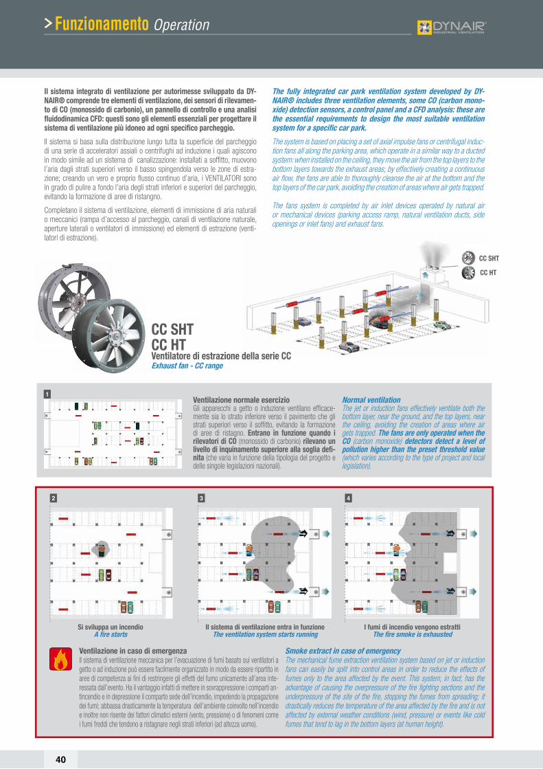
40
Ventilazione in caso di emergenzaIl sistema di ventilazione meccanica per l’evacuazione di fumi basato sui ventilatori a getto o ad induzione può essere facilmente organizzato in modo da essere ripartito in aree di competenza ai fi ni di restringere gli effetti del fumo unicamente all’area inte-ressata dall’evento. Ha il vantaggio infatti di mettere in sovrappressione i comparti an-tincendio e in depressione il comparto sede dell’incendio, impedendo la propagazione dei fumi; abbassa drasticamente la temperatura dell’ambiente coinvolto nell’incendio e inoltre non risente dei fattori climatici esterni (vento, pressione) o di fenomeni come i fumi freddi che tendono a ristagnare negli strati inferiori (ad altezza uomo).
Smoke extract in case of emergencyThe mechanical fume extraction ventilation system based on jet or induction fans can easily be split into control areas in order to reduce the effects of fumes only to the area affected by the event. This system, in fact, has the advantage of causing the overpressure of the fi re fi ghting sections and the underpressure of the site of the fi re, stopping the fumes from spreading; it drastically reduces the temperature of the area affected by the fi re and is not affected by external weather conditions (wind, pressure) or events like cold fumes that tend to lag in the bottom layers (at human height).
Normal ventilationThe jet or induction fans effectively ventilate both the bottom layer, near the ground, and the top layers, near the ceiling, avoiding the creation of areas where air gets trapped. The fans are only operated when the CO (carbon monoxide) detectors detect a level of pollution higher than the preset threshold value (which varies according to the type of project and local legislation).
Ventilazione normale esercizioGli apparecchi a getto o induzione ventilano effi cace-mente sia lo strato inferiore verso il pavimento che gli strati superiori verso il soffi tto, evitando la formazione di aree di ristagno. Entrano in funzione quando i rilevatori di CO (monossido di carbonio) rilevano un livello di inquinamento superiore alla soglia defi -nita (che varia in funzione della tipologia del progetto e delle singole legislazioni nazionali).
I fumi di incendio vengono estrattiThe fi re smoke is exhausted
Si sviluppa un incendioA fi re starts
Il sistema di ventilazione entra in funzioneThe ventilation system starts running
2 3 4
1
Funzionamento Operation
Il sistema integrato di ventilazione per autorimesse sviluppato da DY-NAIR® comprende tre elementi di ventilazione, dei sensori di rilevamen-to di CO (monossido di carbonio), un pannello di controllo e una analisi fl uidodinamica CFD: questi sono gli elementi essenziali per progettare il sistema di ventilazione più idoneo ad ogni specifi co parcheggio.
Il sistema si basa sulla distribuzione lungo tutta la superfi cie del parcheggio di una serie di acceleratori assiali o centrifughi ad induzione i quali agiscono in modo simile ad un sistema di canalizzazione: installati a soffi tto, muovono l’aria dagli strati superiori verso il basso spingendola verso le zone di estra-zione; creando un vero e proprio fl usso continuo d’aria, i VENTILATORI sono in grado di pulire a fondo l’aria degli strati inferiori e superiori del parcheggio, evitando la formazione di aree di ristangno.
Completano il sistema di ventilazione, elementi di immissione di aria naturali o meccanici (rampa d’accesso al parcheggio, canali di ventilazione naturale, aperture laterali o ventilatori di immissione) ed elementi di estrazione (venti-latori di estrazione).
The fully integrated car park ventilation system developed by DY-NAIR® includes three ventilation elements, some CO (carbon mono-xide) detection sensors, a control panel and a CFD analysis: these are the essential requirements to design the most suitable ventilation system for a specifi c car park.
The system is based on placing a set of axial impulse fans or centrifugal induc-tion fans all along the parking area, which operate in a similar way to a ducted system: when installed on the ceiling, they move the air from the top layers to the bottom layers towards the exhaust areas; by effectively creating a continuous air fl ow, the fans are able to thoroughly cleanse the air at the bottom and the top layers of the car park, avoiding the creation of areas where air gets trapped.
The fans system is completed by air inlet devices operated by natural air or mechanical devices (parking access ramp, natural ventilation ducts, side openings or inlet fans) and exhaust fans.
CC SHTCC HTVentilatore di estrazione della serie CCExhaust fan - CC range
CC HT
CC SHT

41
Benefi ciBenefits
PROGETTAZIONE Ottimizzazione degli spazi grazie agli ingombri
ridotti dei ventilatori e alla loro fl essibilità di installazione sia nelle costruzioni ex-novo sia negli interventi di rinnovo e/o messa a norma;
Risparmio di tempo di progettazione in quanto non va previsto e studiato un complesso siste-ma di canalizzazione;
Effi cacia del sistema misurabile grazie alla mo-dellazione CFD (analisi fl uidodinamica);
Maggiore assistenza e servizio di pre-vendita da parte del costruttore;
Valutazione economica preliminare del progetto entro 24 ore;
Costi fi nali in linea con i costi attesi.
INSTALLAZIONE Eliminazione di costosi e complessi sistemi di
condotti e griglie; Facilità di installazione dei ventilatori che ga-
rantisce un notevole risparmio in termini di ore/lavoro;
Il ridotto ingombro dei ventilatori facilita l’installazio-ne di altri impianti (rete sprinkler, illuminazione ecc.);
Facilità di manutenzione ordinaria e straordinaria.
FUNZIONAMENTO Importanti economie di esercizio derivanti
dalla peculiarità del sistema: Possibilità di ventilazione parziale o solo se
necessario: i rilevatori di CO (monossido di car-bonio) e i sensori di fumo assicurano infatti che siano attivati solo i ventilatori nelle aree in cui sono stati superati i livelli di inquinamento o in quelle in cui si è innescato l’incendio;
Minore potenza globale necessaria grazie a una progettazione accurata che garantisce un ottimale dimensionamento dell’impianto di ventilazione; in particolare, i ventilatori di immissione e estrazione possono essere di dimensioni minori in quanto i ventilatori a getto o a induzione generano una per-dita di carico trascurabile rispetto ai sistemi cana-lizzati.
UTILIZZO Migliore qualità dell’aria respirabile: il sistema crea
un fl usso dinamico in grado di mescolare i vari strati dell’aria e di eliminare le zone di ristagno;
Sicurezza ottimizzata in caso di incendio: l’estrazione rapida ed effi cace dei fumi tossici permette di proteggere al meglio le vie di fuga, di facilitare l’accesso alle squadre d’intervento, di favorire l’incolumità delle persone e di mi-nimizzare gli effetti dell’incendio sulle strutture dell’edifi cio.
DESIGN The compact size of the fans allows to optimi-
se the spaces and their fl exibility of installation both when building new properties or refurbi-shing and/or certifying existing buildings;
It saves design time as it does not require a complex ducted system to be designed and implemented;
The system effectiveness can be measured with CFD (fl uid dynamics calculation) modelling;
It allows the project designer to benefi t from a better pre-sales customer service.
The project can be fi nancially assessed within 24 hours;
Final costs are in line with expected costs.
INSTALLATION It removes the need for costly and complex duc-
ted and grilled systems; The fans are easy to install, ensuring time saving
in terms of hours of work; The reduced size of the fans easies installation of
other systems (sprinklers, lighting etc); Ease of scheduled and breakdown maintenance.
OPERATION Major savings in running costs ensured
by the system distinctive features: Ventilation can be fully or partly operated: the
CO (carbon monoxide) detectors and the smoke sensors, in fact, ensure that only the ventilators located in the areas where pollution levels are exceeded or where a fi re has started are ena-bled;
Less total power required as the accurate design ensures the optimal size of the ventilation system; more specifi cally, the inlet and exhaust fans can be smaller as the jet or induction fans generate a negligible pressure drop compared to ducted sy-stems.
USE Better quality of breathable air: the system cre-
ates a continuous airfl ow able to mix the diffe-rent layers of air and to avoid areas where air gets trapped;
Optimised safety in the event of a fi re: fast and effective toxic fume extraction, leading to safer escape routes, easier access for the emergen-cy teams, promoting people safety and minimi-sing the effects of fi re on the building structu-res.
Rispetto ad un sistema di ventilazione canaliz-zato l’innovativo sistema basato sui ventilatori a getto o a induzione genera molteplici benefi ci in termini di economicità e di effi cienza inerenti a progettazione, all’installazione, al funziona-mento e all’utilizzo.
Compared to a ducted ventilation system, the innovative based on jet or induction fans system ensures multiple benefi ts in terms of low cost and effi ciency associated with its design, installation, operation and usage.

42
Strumenti e Servizi Systemdesignandservices
COME FUNZIONAL’analisi CFD è essenziale per assicurare che tutte le aree del parcheggio siano ventilate correttamente e che, in caso di incendio, l’estrazione dei fumi avvenga in modo ottimale. Inoltre, è necessaria per definire il preciso dimen-sionamento del sistema di ventilazione e il corretto posizionamento dei ven-tilatori a getto o ad induzione e altri ventilatori di estrazione e/o immissione.Tale analisi si basa su una simulazione che integra variabili quali il numero di ricambi/ora necessari (definiti dalla legislazione specifica ad ogni paese), il vo-lume e la direzione dell’aria e le caratteristiche strutturali di ogni singolo par-cheggio (in modello 3D). I dati elaborati generano degli scenari dinamici basati sui profili di velocità dell’aria, sul moto delle particelle e sulla distribuzione dei flussi di aria. Ne risulta un progetto finale fatto su misura. Questo metodico processo consente non solo di misurare l’effettiva efficacia del sistema, ma anche di garantirne l’ottimizzazione da un punto di vista economico in quanto si evitano progetti sovra-dimensionati.
HOW IT WORKSCFD calculation is essential to ensure that all areas of the car park are correctly ventilated and, in the event of fire, fume extraction is optimised. It is also required to establish the accurate size of the ventilation system and the correct positioning of the jet or induction fans and of other exhaust and/or inlet fans.This calculation is based on simulation, combining variables such as the required number of air changes/hours (established by local legislations), air volume and direction and structural features of each car park (in a 3D model). The processed data generate dynamic scenarios based on air speed profiles, particle movement and airflow distribution. This allows a customised solution to be produced. This methodical approach ensures not only to assess the system effectiveness, by also the most cost-effec-tive solution as over-sized projects are avoided.
DALLA PROGETTAZIONE AL SERVIZIO AL CLIENTELa progettazione di un sistema di ventilazione per autorimesse implica lo studio dei problemi di fluidodinamica ad esso inerenti. Come noto, i calcoli relativi al moto dei fluidi sono estremamente complessi: effettuarli manualmente accresce il rischio di errore, compromettendo il corret-to funzionamento del sistema di ventilazione ideato e, di conseguenza, la salute e la sicurezza degli utilizzatori.In questa fase fondamentale della progettazione, DYNAIR® è in grado di offrire un importante e reale supporto ingegneristico grazie all’espe-rienza maturata negli anni e all’alto livello di preparazione dello staff tecnico che padroneggia l’utilizzo del Software CFD (Computational Fluid Dynamics), uno strumento evoluto di analisi fluidodinamica computazionale.
FROM DESIGN TO CUSTOMER SERVICEDesigning a car park ventilation system requires assessing issues associated with fluid dynamics. The high complexity of fluid dynamics calcu-lation is well known: manual calculation increases the risk of making mistakes, compromising the correct operation of the ventilation system designed and, therefore, users' health and safety. During this crucial design stage, DYNAIR® is able to offer a real and valuable engineering support thanks to the experienced and highly skilled technical staff, who boasts an in-depth knowledge of the CFD software, an advanced computational fluid dynamics calculation tool.
REALIZZAZIONE DEL MODELLO 3D DEL PARCHEGGIO E DEI SUOI VARI COMPARTIA questo livello dell’analisi sono note solo le condizioni geometriche e matematiche imposte al modello (condizioni al contorno del sistema).
3D MODELLING OF THE CAR PARK AND ITS DIFFERENT SECTIONSAt this level of calculation, only thegeometrical and mathematical conditions required by the model are known (bounding conditions of the system).

43
Strumenti e Servizi Systemdesignandservices
DYNAIR® si pregia di assistervi con competenza ed esperienzain ogni singola fase di un progetto di ventilazione per autorimesse.
DYNAIR® is able to assist you with its know-how and experienceduring each stage of the ventilation project for car parks.
IMPOSTAZIONE DELL’ANALISI E ELABORAZIONE DEGLI SCENARIIntroduzione delle condizioni al contorno e delle condizioni iniziali quali pressione esterna e temperatura dell’aria immessa dall’esterno; settaggio di tutti i parametri strutturali (bocche di lupo, rampe di accesso...) e impostazione delle condizioni di funzionamento (defi nizione materiali, assegnazione della curva delle prestazioni aerauliche al modello dei ventilatori); defi nizione della meshatura (quantità di volumi primitivi in cui suddividere il modello).Elaborazione dei dati e valutazione di ogni scenario variando tipologia, quantità e posiziona-mento dei ventilatori.
ANALISI DEI RISULTATI E SVILUPPO DI UNA SOLUZIONE DI EQUILIBRIOLo sviluppo dell’analisi può essere fatto verifi cando le velocità dell’aria all’interno dei singoli comparti del parcheggio. I grafi ci riportati rappresentano l’andamento della velocità media di attraversamento dell’aria su un piano di sezione.
CALCULATION SET-UP AND SCENARIO DEVELOPMENTIntroduction of boundary conditions and initial conditions such as external pressure and out-side air temperature; structural parameter set-up (light wells, access ramps...) and operating conditions set-up (material defi nition, assignment of air performance curve to the fan model), mesh defi nition (quantity of primary volumes the model must be split into).Data processing and assessment of each scenario by changing the type, quantity and position of the fans.
ANALYSING THE RESULTS AND DEVELOPING A BALANCED SOLUTIONThe data can be analysed by checking the air speed inside each section of the car park.The graphs shown below represent the average air speed on a sectional fl oor.
SCENARIO FINALEIn questa ultima fase avviene il controllo fi nale dell’effi cacia del sistema.
FINAL SCENARIODuring this last stage, system effectiveness is put to the test.
DYNAIR® stabilisce, in fase di progettazione, la logica di comando dei sensori CO (monossido di carbonio) più adeguata ad ogni evenienza, al fi ne di migliorare l’effi cienza del sistema di ventilazione e la sua compartimentazione. Dynair propone un sistema completo di sensori CO in grado di rilevare la concentrazione di monossido di carbonio tale per cui venga necessario lavare il volume d’aria interessato.
At the design stage DYNAIR® establishes the most suitable CO (carbon monoxide) sensor control logic for any eventuality, in order to improve the ventilation system effi ciency and its sectioning. DYNAIR® offers a full range of CO sensors able to detect carbon monoxide concentration requiring the affected air volume to be cleansed.
SISTEMI AUSILIARI DI CONTROLLOANCILLARY MONITORING SYSTEMS

Member of
9CA
1011
REV
/03
Maico Italia S.p.A. Via Maestri del Lavoro, 12 - 25017 Lonato del Garda (Brescia) ItaliaTel. +39 030 9913575 - Fax +39 030 9913766
Caratteristiche e dati tecnici possono variare senza preavviso, mantenendo inalterati i principali parametri funzionali dei modelli. Tutti i marchi citati sono di proprietà di Maico Italia S.p.A. Tutti i diritti sono riservati.Features and technical data can vary without prior notice without modifying the main functional parameters of the products. All trademarks mentioned are the property of Maico Italia S.p.A. All rights reserved.


![Competitor Analysis - DidaWiki [DidaWiki]didawiki.di.unipi.it › lib › exe › fetch.php › dm › 11-mains...Competitor Analysis Analisi dei dati ed estrazione della conoscenza](https://img.pdfslide.us/doc/110x75/5f1005027e708231d4470ae7/competitor-analysis-didawiki-didawiki-a-lib-a-exe-a-fetchphp-a-dm-a.jpg)