Embed Size (px)
Citation preview
Questions, problems, missing parts? Before returning to your retailer, call our customer service department at 1-877-319-3757, 7 a.m. - 5 p.m., CST, Monday - Friday.
www.homewerksww.com
VENTILATING BATH FAN WITH LIGHT
MODEL #7125-02
Español p. 14
Feb. 13, 2012
Hoover is a registerd trademark of Techtronic Industries Limited and is being used underlicense by Homewerks Worldwide, LLC.

2
TABLE OF CONTENTS
PRODUCT SPECIFICATIONS
SPECIFICATIONS SPECIFICATIONSAir flow - 70CFM Power consumption - 113 total Watts
(2 x 40 Watt bulbs plus 33 Watt motor)120V, 60Hz Exhaust fan speed - 1032 rpmDuct diameter - 4 in. Weight - 13 lbsSound output - 2.0 Sones
Product Specifications ........................................................................................................................2
Package and Hardware Contents.......................................................................................................3
Safety Information ..............................................................................................................................4
Preparation .........................................................................................................................................5
Assembly Instructions – Existing Construction ...................................................................................6
Assembly Instructions – New Construction ......................................................................................10
Care and Maintenance ..................................................................................................................... 11
Troubleshooting ................................................................................................................................12
Warranty ...........................................................................................................................................13
www.homewerksww.com

3
PACKAGE CONTENTS
PART DESCRIPTION QUANTITY PART DESCRIPTION QUANTITY
A Fan body 1 EDecorative finials(chrome, brushed nickel, brushed bronze, white)
4
B Grille 1 F Suspension bracket I 2C Glass globe 1 G Suspension bracket II 2D Light socket assembly 1
HARDWARE CONTENTS (not actual size)
A
C
B
D
E
F
G
AA BB CC DD EE FF GG HH
Long Wood Screw
Short Machine Screw
Long Machine Screw
Flat Washer
Lock Washer
Mounting Nut
Long Connect Screw
Plastic Ring
Qty. 8 Qty. 4 Qty. 2 Qty. 2 Qty. 2 Qty. 1 Qty. 1 Qty. 1

4
SAFETY INFORMATION
Please read and understand this entire manual before attempting to assemble, operate or install the product.
1. Always disconnect the power supply prior to servicing the fan, motor or junction box.2. Installation work must be carried out by a qualified person(s) in accordance to all local and
safety codes including the rules for fire-rated construction.3. Follow all local building, safety and electrical codes as well as NEC (National Electrical Code)
and OSHA (Occupational Safety and Health Act).4. Electric Service supply must be 120V 60Hz.5. This unit must be properly grounded.6. Do not bend or kink the power wires.7. Exercise care to not damage existing wiring when cutting or drilling into walls or ceilings.8. Sufficient air supply is required for proper combustion and the exhaustion of gases through
the chimney (flue) of fuel burning equipment to prevent back-drafting. See the standards of NFPA (National Fire Protection Association) and ASHRAE (American Society for Heating Refrigeration and Air Conditioning Engineers) and the local building code authorities.
9. Do not use this fan with any solid state control device. Such as a remote control, dimmer switch, or certain timers. Mechanical timers are not solid state devices.
10. This ventilation fan is approved for use over a bathtub or shower when installed in a GFCI protected circuit. Do not use fans over a bathtub or shower that are not approved for that application and marked accordingly.
11. Do not install in a cooking area.12. Do not use to exhaust hazardous or explosive vapors.13. Fans should always be vented to the exterior and in compliance with local codes.14. Do not install in a ceiling with insulation greater than R42.15. Duct work should be installed in a straight line with minimal bends.16. Duct work size must be the same size as the discharge and should not be reduced. Reducing
the duct size, may increase fan noise.17. Prior to service or cleaning this unit, shut off power supply at the panel and lock to
prevent the power from being turned on. If the panel cannot be locked, clearly mark the panel with a warning tag to prevent the power from being turned on.
18. Use this unit in the manner intended by the manufacturer. If you have any questions please call the manufacturer (customer service number located on first page).
www.homewerksww.com

5
PREPARATION
WARNING: Turn off electricity at breaker box before beginning installation.Carefully remove unit from carton.Before beginning assembly of product, make sure all parts are present. Compare parts with package contents list and hardware contents. If any part is missing or damaged, do not attempt to assemble the product. Contact customer service for replacement parts. Check area above installation location to be sure that wiring can run to the planned location and that duct work can be run and the area is sufficient for proper ventilation.Inspect duct work and wiring before proceeding with installation.Before installaion, provide inspection and future maintenance access at a location that will not interfere with installation work.Do not attempt to install this fan in a wall or vaulted ceiling. This fan is for standard horizontal ceiling installation only.You may need the help of a second person to install this fan; one person on the attic side and one on the room side.
Tools required for assembly (not included): Electric Drill, Drill Bits, Phillips Head Screwdriver, Utility Knife
Other supplies you will need (not included): Duct Tape, Wire nuts, 2 40Watt Candelabra Bulbs
Note: Installations may vary depending on how the previous bath fan was installed. Supplies necessary for the installation of your bath fan are not all included; however, most are available at your local home improvement or hardware store.
DIMENSIONS
Ceiling Opening (L)
Ceiling Opening (W)
Ceiling Opening (H)
Body Dimension (L)
Body Dimension (W)
Body Dimension (H)
9-5/16 in. 10-1/4 in. 6-1/4 in. 9-1/4 in. 10-1/8 in. 5-13/16 in.
www.homewerksww.com

6
ASSEMBLY INSTRUCTIONS
INSTALLATION IN EXISTING CONSTRUCTION
Note: Installing the fan body in an existing building requires an accessible area (attic or crawl space) above the planned installation location. If you do not have attic space, you will not be able to install this fan.
CAUTION: MAKE SURE POWER IS SWITCHED OFF AT SERVICE PANEL BEFORE STARTING INSTALLATION.
1. Existing Fan – remove the existing fan and check to make sure the opening is large enough to accommodate new fan body.
Use the grille (B) from the new exhaust fan as a template to mark position of the opening. Fig. 1
2. Cut out opening for the fan body (A). If hole is too large the fan globe will not hide it. Fig. 2
Note: Ceiling repair may be required if your existing hole does not meet the dimensions of the new fan.
3. Insert the suspension brackets (G) into the fan body (A). Fig. 3
If joist spacing is between 21-1/4 in. and 23-1/2 in., connect suspension bracket I (F) and suspension bracket II (G) using short machine screws (BB).
Fig. 1
Fig. 2
Fig. 3
www.homewerksww.com
F
G
Short machine screws

7
ASSEMBLY INSTRUCTIONS
4. Position the fan body (A) so that the grille (B) is flush with the ceiling board. Fig. 4
5. Mount the fan body (A) with grille (B) in place to joist using the suspension brackets (G) and long wood screws (AA).
6. Remove junction box cover from side of fan body (A). Fig.6
CAUTION: If your electrical wires do not match the colors listed, you must determine what each house wire represents before connecting. You may need to consult an electrical contractor to determine safely.
7. Connect wires as shown in wiring diagram. Using wire nuts (not included) connect house electrical wires to ventilating fan wires: black to switch, white to nuetral, green to ground. Fig. 7
Fig. 4
Fig. 5
Fig. 6
Fig. 7
Grille Ceiling board
www.homewerksww.com
to switchto neutral
to switch
to neutral
to ground
to ground
to 120V AC 60Hz
Up to 60 Watts
Junction box
automatic terminal switch
FAN HOUSING
LIGHT HOUSING
black wire
black wire
white wire
white wire
Capacitor for long life ofmotor green wire
green wire
motor
8
ASSEMBLY INSTRUCTIONS
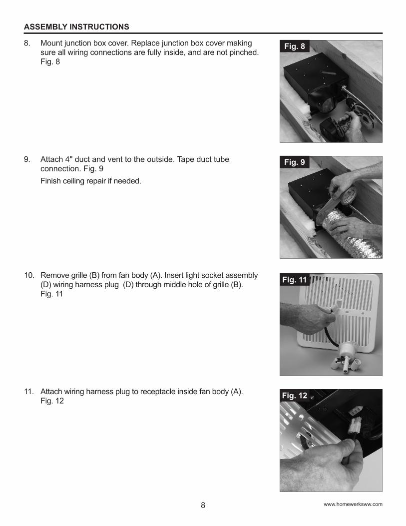
8. Mount junction box cover. Replace junction box cover making sure all wiring connections are fully inside, and are not pinched. Fig. 8
9. Attach 4" duct and vent to the outside. Tape duct tube connection. Fig. 9
Finish ceiling repair if needed.
10. Remove grille (B) from fan body (A). Insert light socket assembly (D) wiring harness plug (D) through middle hole of grille (B). Fig. 11
11. Attach wiring harness plug to receptacle inside fan body (A). Fig. 12
Fig. 8
Fig. 9
Fig. 11
Fig. 12
www.homewerksww.com
9
Fig. 13
Fig. 14
Fig. 15
ASSEMBLY INSTRUCTIONS
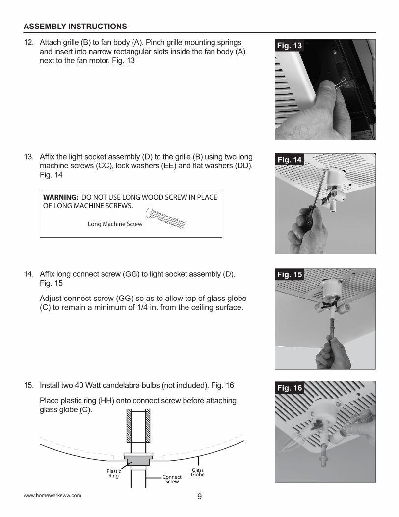
12. Attach grille (B) to fan body (A). Pinch grille mounting springs and insert into narrow rectangular slots inside the fan body (A) next to the fan motor. Fig. 13
13. Affix the light socket assembly (D) to the grille (B) using two long machine screws (CC), lock washers (EE) and flat washers (DD). Fig. 14
Long Machine Screw
WARNING: DO NOT USE LONG WOOD SCREW IN PLACE OF LONG MACHINE SCREWS.
14. Affix long connect screw (GG) to light socket assembly (D). Fig. 15
Adjust connect screw (GG) so as to allow top of glass globe (C) to remain a minimum of 1/4 in. from the ceiling surface.
15. Install two 40 Watt candelabra bulbs (not included). Fig. 16
Place plastic ring (HH) onto connect screw before attaching glass globe (C).
Fig. 16
www.homewerksww.com
PlasticRing Connect
Screw
GlassGlobe

10
ASSEMBLY INSTRUCTIONS
Fig. 20
Fig. 17
Fig. 18
Fig. 19
Grille Ceiling board
16. Mount glass globe (C) to connect screw (GG) with one of the decorative finials (G). Fig. 17
Turn on power at the service panel after finishing installation.
INSTALLATION IN NEW CONSTRUCTION
CAUTION: MAKE SURE POWER IS SWITCHED OFF AT SERVICE PANEL BEFORE STARTING INSTALLATION.
1. Insert the suspension brackets (F) into the fan body (A). If joist spacing is between 21-1/4 in. and 23-1/2 in., connect suspension bracket I (E) and suspension bracket II (F). Fig. 18
2. Position the fan body (A) so that the grille (B) will be flush with the ceiling board when installed. Fig. 19
3. Go to step 10 (page 8) to mount light socket assembly (D) and grille (B). Mount the fan body (A) with the grille (B) and light socket assembly (D) in place to the joist using the suspension brackets and long wood screws (AA). Fig. 20
Go to step 5 (page 7). Follow steps to connect fan body (A), wiring, light socket assembly (D) and glass globe (C).
www.homewerksww.com

11
Fig. 21
Fig. 22
Fig. 23
CARE AND MAINTENANCE
1. Unscrew the decorative finial (D) to remove the glass globe (C). Fig. 21
2. Wash and clean the glass globe (C) in a sink and dry with a soft cloth. Fig. 22
3. Remove dust and dirt from fan body (A) with vacuum cleaner. Fig. 23
WARNING: Disconnect power supply before servicing. See SAFETY INFORMATION (page 4) in this manual before proceeding. Routine maintenance should be done at least once a year.
CAUTION: • Never use solvents, thinner or harsh chemicals for cleaning the fan.• Do not allow water to enter the motor.• Do not inmmerse metal finial parts in water.• Do not immerse resin parts in water over 140 degrees Fahrenheit.
www.homewerksww.com

12
TROUBLESHOOTING
PROBLEM POSSIBLE CAUSE CORRECTIVE ACTION
The fan seems louder than it should
CFM too greatBe sure the CFM rating on the fan matches the size of your room.
Damper not working properly or damaged
Check damper to ensure it is opening and closing properly. If the damper has become damaged, please call Customer Service for a replacement.
Bend in duct too close to fan dischargeBe sure you do not have any sharp bends in duct closer than 18" to the fan discharge.
Fan discharge reduced to fit smaller duct
Use recommended size ducting to reduce fan noise
Fan body not securely attached Be sure the fan is securely attached to your ceiling joists.
CARE AND MAINTENANCE
4. Dampen cloth with water and mild dish detergent. Wipe the fan body (A) and dry with a soft dry cloth. Fig. 24
5. Replace the glass globe (C) and re-attach the deorative finial (D). Fig. 25
Fig. 24
Fig. 25
www.homewerksww.com
13Printed in China
LIMITED 5-YEAR WARRANTY
If this product fails due to a defect in materials or workmanship at any time during the first FIVE years of ownership, the manufacturer will replace it free of charge, postage-paid at their option. Simply contact Customer Service at (1-877-319-3757) or visit our website www.homewerksww.com for replacement information. This warranty does not cover products which have been abused, altered, damaged, misused, cut or worn. This warranty does not cover use in commercial applications. Use only Homewerks genuine warranty repair replacement parts to repair this fan. Use of non-genuine repair parts will void your warranty. The manufacturer DISCLAIMS all other implied or express warranties including all warranties of merchantability and/or fitness for a particular purpose. As some states do not allow exclusions or limitations on an implied warranty, the above exclusions and limitations may not apply. This warranty gives you specific legal rights, and you may have other rights that vary from state to state.This warranty is limited to the replacement of defective parts only. Labor charges and/or damage incurred during installation, repair, replacement as well as incidental and consequential damages connected with the above are excluded. Any damage to this product as a result of neglect, misuse, accident, imporper installation or use other than the purpose SHALL VOID THIS WARRANTY.Shipping costs for return product as part of a claim on the warranty must be paid for by the customer.Inquiries regarding warranty claims can be directed to 1-877-319-3757, 7 a.m. - 5 p.m., CST, Monday - Friday.
TROUBLESHOOTING
PROBLEM POSSIBLE CAUSE CORRECTIVE ACTION
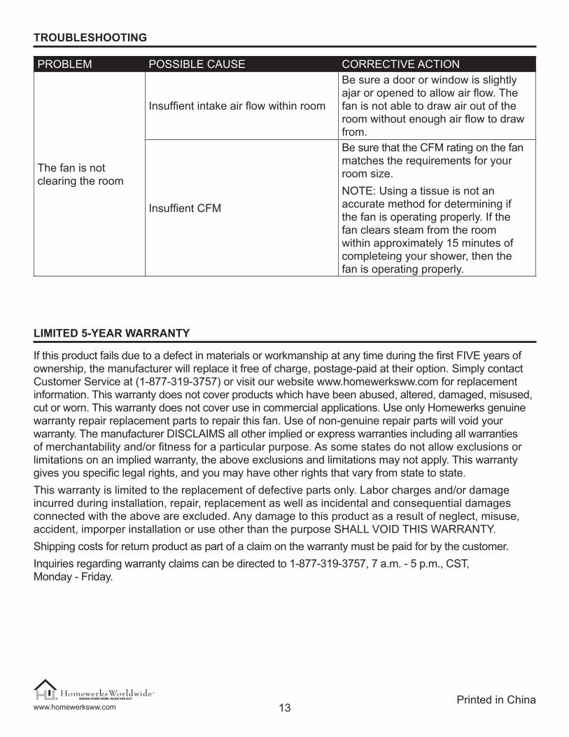
The fan is not clearing the room
Insuffient intake air flow within room
Be sure a door or window is slightly ajar or opened to allow air flow. The fan is not able to draw air out of the room without enough air flow to draw from.
Insuffient CFM
Be sure that the CFM rating on the fan matches the requirements for your room size.NOTE: Using a tissue is not an accurate method for determining if the fan is operating properly. If the fan clears steam from the room within approximately 15 minutes of completeing your shower, then the fan is operating properly.
www.homewerksww.com

Feb. 13, 2012
¿Preguntas, problemas, piezas faltantes? Antes de volver a la tienda, llame a nuestro Departamento de Servicio al Cliente al 1-877-319-3757, hora central estándar, de lunes a viernes..
www.homewerksww.com
VENTILADOR PARA BAÑO CON LUZ
MODELO #7125-02
Hoover es una marca comercial registrada de Techtronic Industries Limited y se utiliza bajo licencia de Homewerks Worldwide, LLC.

15www.homewerksww.com
TABLE OF CONTENTS
ESPECIFICACIONES DEL PRODUCTO
ESPECIFICACIONES ESPECIFICACIONESFlujo de aire: 1,98 m3/min Consumo eléctrico: 113 vatios en total (bombillas
de 2 x 40 vatios y un motor de 33 vatios)120V, 60Hz Velocidad del extractor: 1.032 rpmDiámetro del conducto: 10,16 cm Peso: 5.89 kgPotencia de sonido: 2,0 sonios
Especificaciones del producto ..........................................................................................................15
Contenido del paquete .....................................................................................................................16
Aditamentos......................................................................................................................................16
Información de seguridad .................................................................................................................17
Preparación ......................................................................................................................................18
Instrucciones de ensamblaje – INSTALACIÓN EN FABRICACIÓN EXISTENTE ............................19
Instrucciones de ensamblaje – INSTALACIÓN EN FABRICACIONES NUEVAS ............................23
Cuidado y mantenimiento .................................................................................................................24
Solución de problemas .....................................................................................................................25
Garantía............................................................................................................................................26

16 www.homewerksww.com
CONTENIDO DEL PAQUETE
PIEZA DESCRIPCIÓN CANTIDAD PIEZA DESCRIPCIÓN CANTIDAD
A Cuerpo del ventilador 1 ERemates decorativos (cromo, níquel cepillado, bronce cepillado, blanco)
4
B Rejilla 1 F Abrazadera de suspensión I 2C Pantalla de vidrio 1 G Abrazadera de suspensión II 2
DEnsamblaje del portalámpara
1
ADITAMENTOS (no es el tamaño real)
AA BB CC DD EE FF GG HH
Tornillo para madera largo
Tornillo para metal corto
Tornillo para metal largo
Arandela plana
Arandela de seguridad
Tuerca de montaje
Tornillo de conexión
larga
De plásticoanillo
Qty. 8 Qty. 4 Qty. 2 Qty. 2 Qty. 2 Qty. 1 Qty. 1 Qty. 1
A
C
B
D
E
F
G

17www.homewerksww.com
INFORMACIÓN DE SEGURIDAD
Lea y comprenda completamente este manual antes de intentar ensamblar, usar o instalar el producto.
1. Desconecte siempre el suministro de electricidad antes de realizar tareas de mantenimiento en el ventilador, el motor o la caja de unión.
2. El trabajo de instalación debe estar a cargo de personas calificadas, de acuerdo con todos los códigos locales y de seguridad, incluidas las normas para fabricación con resistencia al fuego.
3. Respete todos los códigos locales eléctricos y de seguridad del edificio, además del Código nacional de electricidad (NEC, por sus siglas en inglés) y el de la Administración de Salud y Seguridad Ocupacional (OSHA, por sus siglas en inglés).
4. El suministro de energía eléctrica debe ser de 120 V 60 Hz.5. Esta unidad debe tener una conexión a tierra adecuada.6. No doble ni pliegue los conductores de fuerza.7. Cuando corte o taladre las paredes o el techo, tenga cuidado de no dañar el cableado eléctrico
existente.8. Es necesario un suministro de aire adecuado para que se produzca una combustión apropiada
y la extracción de gases a través de chimeneas (tiro) del equipo de combustión para evitar la explosión de flujo de aire en retroceso. Consulte las normas de la Asociación Nacional de Protección contra Incendios (NFPA, por sus siglas en inglés), la Sociedad Americana de Ingenieros para Calefacción, Refrigeración y Aire Acondicionado (ASHRAE, por sus siglas en inglés) y las autoridades del código de construcción local.
9. No use este ventilador con dispositivos de control de estado sólido, por ejemplo, un control remoto, un regulador de intensidad o determinados temporizadores. Los temporizadores mecánicos no son dispositivos de estado sólido.
10. Este ventilador está aprobado para su uso sobre bañeras o duchas cuando se instala con un interruptor de circuitos de falla de conexión a tierra (GFCI, por sus siglas en inglés). No use ventiladores sobre bañeras o duchas que no estén aprobadas ni marcadas para dicha aplicación.
11. No lo instale en áreas de cocina.12. No lo use para extraer vapores peligrosos o explosivos.13. Los ventiladores deben contar siempre con una salida al exterior y que cumpla con los códigos
locales.14. No instale en un techo con aislamiento superior a R42.15. Los componentes para conductos se deben instalar en línea recta, con el mínimo de dobleces.16. El tamaño de los componentes para conductos debe representar el mismo tamaño de la descarga
y no se debe reducir. Puede reducir el tamaño del conducto, pero los tamaños menores pueden incrementar el ruido del ventilador.
17. Antes de realizar tareas de mantenimiento o limpiar la unidad, corte el suministro de electricidad en el panel y bloquéelo a fin de impedir la activación de la alimentación. Si no puede bloquear el panel, márquelo claramente con una etiqueta de advertencia para evitar que otros conecten la alimentación.
18. Use esta unidad solo de la manera prevista por el fabricante. Si tiene preguntas, llame al fabricante (al número del Servicio al Cliente que aparece en la primera página).

18 www.homewerksww.com
PREPARACIÓN
ADVERTENCIA: Desconecte la electricidad en la caja del interruptor de circuito antes de comenzar la instalación.Retire con cuidado la unidad de la caja.Antes de comenzar a ensamblar el producto, asegúrese de tener todas las piezas. Compare las piezas con la lista del contenido del paquete y los aditamentos. No intente ensamblar el producto si falta alguna pieza o si están dañadas. Póngase en contacto con el Departamento de Servicio al Cliente para obtener piezas de repuesto. Revise el área situada sobre la ubicación de la instalación para asegurarse de que el cableado se extienda hasta la ubicación planificada, que los componentes para conductos se puedan instalar y que el área sea suficiente para lograr la ventilación adecuada.Revise los componentes para conductos y el cableado antes de continuar con la instalación.Antes de instalar, asegúrese de dejar un sitio de acceso para revisiones y tareas de mantenimiento futuras en un lugar que no interfiera con el trabajo de instalación.No intente instalar este ventilador en una pared o un techo de bóveda. Este ventilador solamente debe instalarse en techos horizontales estándares.Es posible que necesite la ayuda de otra persona para instalar este ventilador; una persona en el ático y otra en la habitación.
Herramientas necesarias para el ensamblaje (no se incluyen): Taladro eléctrico, brocas para taladro, destornillador Philips, cuchillo para uso general
Otros suministros que necesitará (no incluido): Cinta aislante, tuercas de alambre, 2 40Watt Candelabros Lámparas
Note: Installations may vary depending on how the previous bath fan was installed. Supplies necessary for the installation of your bath fan are not all included; however, most are available at your local home improvement or hardware store.
DimensiónAbertura del
techo (L)Abertura del
techo (W)Abertura del
techo (H)Dimensión del
cuerpo (L)Dimensión del
cuerpo (W)Dimensión del
cuerpo (H)9-5/16 in. 10-1/4 in. 6-1/4 in. 9-1/4 in. 10-1/8 in. 5-13/16 in.

19www.homewerksww.com
INSTRUCCIONES DE ENSAMBLAJE
INSTALACIÓN EN FABRICACIÓN EXISTENTE
Nota: La instalación del cuerpo del ventilador en una construc-ción existente requiere de un área accesible (ático o subsuelo) sobre la ubicación planificada de instalación. Si no tiene espacio en el ático, no podrá instalar este ventilador.
PRECAUCIÓN: ASEGÚRESE DE QUE LA ALIMENTACIÓN ESTÉ DESCONECTADA EN EL PANEL DE SERVICIO ANTES DE COMENZAR LA INSTALACIÓN.
1. Ventilador actual: retire el ventilador actual y asegúrese de que la abertura sea lo suficientemente grande para alojar el cuerpo del nuevo ventilador.
Use la rejilla (B) del nuevo extractor como una plantilla para marcar la posición de la abertura. Fig. 1
2. Corte una abertura para el cuerpo del ventilador (A). Si el agujero es demasiado grande, la pantalla del ventilador no lo tapará. Fig. 2
Nota: Es posible que deba reparar su techo si el agujero existente no se adapta a las dimensiones del nuevo ventilador.
3. Coloque las abrazaderas de suspensión (F) en el cuerpo del ventilador (A). Fig. 3
Si el espacio de la vigueta abarca entre 52,71 cm y 57,15 cm, coloque la abrazadera de suspensión I (F) y la abrazadera de suspensión II (G). Para esto, use tornillos cortos de metal (BB).
Fig. 1
Fig. 2
Fig. 3
F
G
Tornillo para metal corto

20 www.homewerksww.com
INSTRUCCIONES DE ENSAMBLAJE
4. Coloque el cuerpo del ventilador (A) de manera que la rejilla (B) quede a ras con el tablero del techo. Fig. 4
5. Instale el cuerpo del ventilador (A) con la rejilla (B) en el lugar adecuado de la vigueta. Para esto, use abrazaderas de suspensión (G) y tornillos largos de madera (AA). Fig. 5
6. Retire la cubierta de la caja de unión del lateral del cuerpo del ventilador (A). Fig. 6
PRECAUCIÓN: Si el color de los cables eléctricos no coincide con los colores enumerados, debe decidir qué representa cada conductor de su casa antes de realizar la conexión. Es posible que necesite consultar a un electricista para tomar una decisión que no implique peligros.
7. Conecte los cables como se muestra en el diagrama de cablea-do. Use empalmes plásticos (no se incluyen) para conectar los cables eléctricos de la casa con los cables del ventilador: negro con negro, blanco con blanco, verde con verde. Fig. 7
Fig. 4
Fig. 5
Fig. 6
Fig. 7
Rejilla Tablero del techo
motor
interruptor de terminal automático
Carcasa del ventilador Caja de unión
to 120V AC 60Hz
Capacitor para una larga duración del motor
Conductor blancoConductor verde
Conductor negro
Al neutro
Al tierra
Al interruptor

21www.homewerksww.com
INSTRUCCIONES DE ENSAMBLAJE
8. Instale la cubierta de la caja de unión. Reemplace la cubierta de la caja de unión asegurándose de que todas las conexiones de cableado estén por completo en el interior, y no queden atrapadas. Fig. 8
9. Fije el conducto de 10,16 cm y haga que ventile hacia el exterior. Cubra con cinta adhesiva la conexión del tubo del conducto.Fig. 9 NOTA: No instale el conducto como se muestra en el siguiente diagrama.
Si es necesario, termine de reparar el techo.
10. Retire la rejilla (B) del cuerpo del ventilador (A). Coloque el enchufe del arnés del cableado (D) del ensamblaje del portalámparas (D) de forma tal que atraviese el orificio medio de la rejilla (B). Fig. 10
11. Fije el enchufe del arnés del cableado en el receptáculo que se encuentra en el interior del cuerpo del ventilador (A). Fig. 11
Fig. 8
Fig. 9
Fig. 11
Fig. 12

22 www.homewerksww.com
Fig. 12
Fig. 13
Fig. 14
INSTRUCCIONES DE ENSAMBLAJE
12. Fije la rejilla (B) en el cuerpo del ventilador (A). Apriete los resortes de montaje de la rejilla e introdúzcalos en las ranuras rectangulares estrechas dentro del cuerpo del ventilador (A) al lado del motor. Fig. 12
13. Fije el ensamblaje del portalámparas (D) en la rejilla (B) usando dos tornillos largos de metal (CC), arandelas de seguridad (EE) y arandelas planas (DD). Fig. 13
Tornillo para metal largo
ADVERTENCIA: NO UTILICE TORNILLOS LARGOS DE MADERA EN LUGAR DE TORNILLOS CORTOS DE METAL
14. Fije el tornillo de conexión largo (GG) en el ensamblaje del portalámparas (D). Fig. 14
Regule el tornillo de conexión (GG) para permitir que la parte superior de la pantalla de vidrio (C) permanezca a un mínimo de 0,64 cm de la superficie del techo.
15. Instale dos bombillas de base candelabro de 40 vatios (no se incluyen). Fig. 15
Coloque el anillo de plástico (HH) en el tornillo de conexión antes de conectar globo de cristal (C).
Fig. 15
(HH)
Anillo de plástico Conecte
el tornillo
Vidrio mundo

23www.homewerksww.com
INSTRUCCIONES DE ENSAMBLAJE
Fig. 19
Fig. 16
Fig. 17
Fig. 18
Rejilla Tablero del techo
16. Instale la pantalla de vidrio (C) para conectar el tornillo (GG) con uno de los remates decorativos (G). Fig. 16
Encienda la alimentación en el panel de servicio después de terminar la instalación.
INSTALACIÓN EN FABRICACIONES NUEVAS
PRECAUCIÓN: ASEGÚRESE DE QUE LA ALIMENTACIÓN ESTÉ DESCONECTADA EN EL PANEL DE SERVICIO ANTES DE COMENZAR LA INSTALACIÓN.
1. Coloque las abrazaderas de suspensión (F) en el cuerpo del ventilador (A). Si el espacio de la vigueta abarca entre 52,71 cm y 57,15 cm, coloque la abrazadera de suspensión I (E) y la abrazadera de suspensión II (F). Fig. 17
2. Coloque el cuerpo del ventilador (A) de manera que la rejilla (B) quede a ras con el tablero del techo cuando se instale. Fig. 18
3. Vaya al paso 10 (página 8) para instalar el ensamblaje del portalámparas (D) y la rejilla (B). Instale el cuerpo del ventilador (A) con la rejilla (B) y el ensamblaje del portalámparas (D) en el lugar adecuado de la vigueta. Para esto, use abrazaderas de suspensión y tornillos largos de madera (AA). Fig. 19
Vaya al paso 5 (página 7). Siga los pasos para conectar el cuerpo del ventilador (A), el cableado, el ensamblaje del portalámparas (D) y la pantalla de vidrio (C).

24 www.homewerksww.com
Fig. 20
Fig. 21
Fig. 22
CUIDADO Y MANTENIMIENTO
1. Desatornille el remate decorativo (D) para retirar la pantalla de vidrio (C). Fig. 20
2. Lave y limpie la pantalla de vidrio (C) en un lavamanos y séquela con un paño suave. Fig. 21
3. Retire el polvo y la suciedad del cuerpo del ventilador (A) con una aspiradora. Fig. 22
ADVERTENCIA: Desconecte el suministro de electricidad antes de realizar tareas de mantenimiento. Consulte la INFORMACIÓN DE SEGURIDAD (página 4) de este manual antes de continuar. Se deber realizar mantenimiento de rutina al menos una vez al año.
PRECAUCIÓN: • Nunca use solventes, disolventes o químicos agresivos para limpiar el ventilador.• No permita que entre agua en el motor.• No sumerja las piezas de metal del remate en agua.• No sumerja las piezas de resina en agua con una temperatura superior a 60 grados Celsius.

25www.homewerksww.com
SOLUCIÓN DE PROBLEMAS
PROBLEMA CAUSA POSIBLE ACCIÓN CORRECTIVA
El ventilador hace más ruido de lo que debería.
Los m3/min son demasiados.Asegúrese de que la clasificación de m3/min en el ventilador coincida con el tamaño de su habitación.
El regulador de tiro no funciona en forma adecuada o está dañado.
Revise el regulador de tiro para garanti-zar que se abra y cierre correctamente. Si el regulador de tiro se ha dañado, llame al Servicio al Cliente para obtener una pieza de repuesto.
El pliegue del conducto está demasia-do cerca de la descarga del ventilador.
Asegúrese de que no haya bordes filosos en el conducto a una distancia inferior a 45,72 cm con respecto a la descarga del ventilador.
La descarga del ventilador se ha reducido para adaptarse a un conducto de menor tamaño.
Utilice los conductos de tamaño recomendado para reducir el sonido del ventilador.
El cuerpo del ventilador no está bien ajustado.
Asegúrese de que el ventilador esté firmemente ajustado a las viguetas del techo.
CUIDADO Y MANTENIMIENTO
4. Humedezca el paño con un detergente suave para platos suave y agua. Limpie y seque con un paño seco y suave el cuerpo del ventilador (A). Fig. 23
5. Vuelva a colocar la pantalla de vidrio (C) y vuelva a fijar el remate decorativo (D). Fig. 24
Fig. 23
Fig. 24

26
GARANTÍA LIMITADA DE 5 AÑOS
Si este producto falla debido a un defecto en el material o la mano de obra en cualquier momento durante los primeros CINCO años de poseerlo, el fabricante lo reemplazará sin cargos y con el franqueo pagado a su discreción. Para obtener información sobre el reemplazo, póngase en contacto con el Servicio al Cliente (1-877-319-3757) o visite nuestro sitio Web, www.homewerksww.com. Esta garantía no cubre productos que hayan sufrido abusos, modificaciones, daños, uso indebido, cortes o desgaste. Esta garantía no cubre el uso con fines comerciales. Use solo piezas de repuesto genuinas con garantía Homewerks para reparar el ventilador. La utilización de piezas de repuesto no genuinas anulará la garantía. El fabricante RECHAZA todas las demás garantías expresas o implícitas, incluyendo todas las garantías de comerciabilidad e idoneidad para un fin en especial. Debido a que algunos estados no permiten exclusiones o limitaciones en una garantía implícita, las exclusiones y limitaciones anteriores pueden no aplicarse. Esta garantía le otorga derechos legales específicos, pero podría tener también otros derechos que varían según el estado.Esta garantía se limita solo al reemplazo de piezas defectuosas. Quedan excluidos los cargos y/o daños por mano de obra incurridos durante la instalación, reparación o reemplazo, además de los daños incidentales o resultantes relacionados con estos. Cualquier daño a este producto como resultado de negligencia, uso indebido, accidente, instalación inadecuada o cualquier otro uso distinto al descrito en el presente ANULARÁ ESTA GARANTÍA.Los costos de envío por cualquier devolución del producto como parte de una reclamación de garantía estarán a cargo del cliente.Las preguntas relacionadas con reclamos de la garantía pueden realizarse al 1-877-319-3757, de 7 a. m. a 5 p. m., hora central estándar, de lunes a viernes.
SOLUCIÓN DE PROBLEMAS
PROBLEMA CAUSA POSIBLE ACCIÓN CORRECTIVA
El ventilador no ventila la habitación.
Hay un flujo de toma de aire insuficiente dentro de la habitación.
Asegúrese de que una puerta o ventana quede leve o completamente abierta para permitir el ingreso de flujo de aire. El ventilador no absorbe aire de la habitación porque no hay suficiente flujo de aire.
El nivel de m3/min es insuficiente
Asegúrese de que la clasificación de m3/min del ventilador coincida con los requisitos del tamaño de su habitación.NOTA: Utilizar una tela suave no es un método preciso para determinar si el ventilador funciona correctamente. Si el ventilador elimina el vapor de la habitación en aproximadamente 15 minutos de haber terminado de bañarse, entonces el ventilador funciona correctamente.
www.homewerksww.comImpreso en China