Embed Size (px)
Citation preview
UC DAVIS Campus Design Guide
HEATING, VENTILATING, AND AIR CONDITIONING (HVAC) – DIVISION 23 1 July 2017
DIVISION 23 – HEATING, VENTILATING AND AIR CONDITIONING (HVAC)
See Part II for additional information regarding Indoor Pollutant Reduction and Control, Energy Efficiency, etc.
The following design criteria shall be followed regardless of system type or size. Any deviations from these criteria shall be discussed and accepted by the University’s Representative during the preliminary design phase of the project and prior to any construction.
1. Use the most recent American Society of Heating, Refrigeration & Air Conditioning
Engineers (ASHRAE) Climatic Data for Region X to determine outside design conditions. Davis conditions are in parentheses. a. For 100 percent outside air systems use the 0.1 percent summer conditions (103
degrees dry bulb/72 degrees moisture content wet bulb (mcwb)) and the 0.2 percent winter conditions (30 degrees).
b. For 100 percent outside air systems conditioning environmental spaces occupied by animals or insects, special consideration shall be given to design criteria. Sizing of equipment to maintain temperature (and humidity if required) can be critical, depending on the intended usage of the conditioned space. Equipment in some applications shall be sized to accommodate extreme conditions. For 100 percent outside air stand-alone equipment serving these areas, apply 110 degrees dry bulb for summer and 25 degrees winter outside air temperatures. Review the assumptions, including outside air temperatures, with University’s Representative prior to developing basis of design and equipment selection.
2. For recirculating air systems use the 0.5 percent (99 degrees dry bulb/70 degrees mcwb) summer conditions and the 0.6 percent winter conditions (34 degrees).
3. For interior temperature conditions, use 75 degrees for cooling and 70 degrees for heating. More stringent animal care codes may override these criteria.
4. Telecommunications Spaces (IDF, BDF rooms): Temperature range between 68 and 74 degrees F cooling; no heating; Relative Humidity range between 35 percent and 55 percent. See further detail below.
5. For cooling tower selection use the 0.1 percent design wet bulb conditions (74 degrees). Comply with current California Title 24 Cooling Tower Requirements.
6. Internal heat loads: a. Lighting: Per Title 24, Part 6. Refer to Part 2 for additional requirements. b. Equipment: Per manufacturer’s data or ASHRAE 2009 Fundamentals, Ch. 18.
7. People: Per ASHRAE 2009 Fundamentals, Ch. 18. 8. The building pressure shall be slightly positive to ambient, but allow exterior doors to
close automatically. 9. HVAC system noise: Design Classrooms, Libraries, Study Halls and general office spaces
within NC 30 Standards. For large Lecture Halls, Auditoriums, Concert Halls, Recording Studios etc., (where more stringent controls are desirable) consult with the University’s Representative to set standards suitable for the intended uses. Design all other areas
DESIGN CRITERIA
UC DAVIS Campus Design Guide
HEATING, VENTILATING, AND AIR CONDITIONING (HVAC) – DIVISION 23 2 July 2017
within the NC standards recommended in the latest edition of ASHRAE Applications Handbook.
10. Air distribution design: (Deviations from these criteria shall be exercised as necessary for proper air balance and acoustic control. Discuss any deviations with the University’s Representative.) a. Provide adjustable modular core diffusers or double deflection grilles to allow
adjustment. Ceiling return and exhaust grilles shall be egg crate type. Diffusers, grilles and registers shall be selected and laid out so that air velocities at the occupied levels do not exceed 50 fpm.
b. Low pressure ductwork shall be sized at no more than 0.08 inch/100 foot of duct, and not exceeding 1500 fpm.
c. Medium pressure ductwork shall be sized at no more than 0.2 inch/100 foot of duct, and not exceeding 2500 fpm.
11. Hydronic Distribution: a. Pumps shall be selected for stable and efficient operation throughout the entire
operating range not only the peak design operating point. b. Size piping for a maximum friction loss of 3 feet per 100 feet of pipe and a maximum
flow velocity of 7.5 fps inside buildings and 10 fps outside buildings at maximum flows.
12. Outdoor refrigeration equipment, air handlers, and HVAC units require a hose bib and 115 volt electrical receptacle be installed within 25 feet to allow cleaning, service and maintenance.
13. For maintenance and access requirements, refer to Part II, Design Requirements, ‘Access’.
THERMAL COMFORT Comply with latest edition of ASHRAE Standard 55, Thermal Comfort Conditions for Human Occupancy and provide a permanent monitoring system and process for corrective action to ensure building performance to the desired comfort criteria.
The latest edition of ASHRAE Standard 55 Paragraph 7 Evaluation of the Thermal Environment provides guidance on measurement of building performance parameters and two methods for validating performance: (a) Survey Occupants and (b) Analyze Environment Variables. The permanent monitoring system required here may apply either approach; survey or technical system, where the process or system is integrated into the standard operating processes of the building.
VENTILATION Ventilation Rates For Mechanically Ventilated Spaces, increase breathing zone outdoor air ventilation rates to all occupied spaces by at least 30 percent above the minimum rates required by the latest edition of Procedure of voluntary consensus standard ASHRAE 62.1.
UC DAVIS Campus Design Guide
HEATING, VENTILATING, AND AIR CONDITIONING (HVAC) – DIVISION 23 3 July 2017
VENTILATION MONITORING Install permanent monitoring and alarm systems that provide feedback on ventilation system performance to ensure that ventilation systems maintain design minimum ventilation requirements in a form that affords operational adjustments:
1. For mechanical ventilation systems that predominantly serve densely occupied spaces (those with a design occupant density greater than or equal to 25 people per 1000 square feet), install a CO2 sensor within each densely occupied space.
2. For all other mechanical ventilation systems, provide an outdoor airflow measurement device capable of measuring the minimum outdoor airflow rate at all expected system operating conditions within 15 percent of the design minimum outdoor air rate. The University has encountered maintenance difficulties with typical air measurement devices. Consult and review proposed airflow measurement device with University’s Representative before specifying for a project.
REQUIREMENTS FOR CO2 SENSORS To ensure that sensors can reliably indicate that ventilation systems are operating as designed:
1. CO2 sensors shall be located within the breathing zone of the room as defined in the latest edition of ASHRAE Standard 62.1.
2. CO2 sensors shall be certified by the manufacturer to have an accuracy of no less than 75 ppm, factory calibrated or calibrated at start-up, and certified by the manufacturer to require calibration no more frequently than once every 5 years.
3. Required CO2 sensors and outdoor airflow monitors shall be configured to generate an alarm if the indicated outdoor airflow rate drops more than 15 percent below the minimum outdoor air rate required by Standard 62.1 in one of the following ways: a. A building automation system alarm visible to the system operator/engineer. b. An alarm that is clearly visible to or audible by occupants.
CO2 sensors may also be used for demand controlled ventilation provided the control strategy complies with latest edition of Standard 62.1, including maintaining the area-based component of the design ventilation rate.
Space CO2 alarms and demand controlled ventilation set points shall be based on the differential corresponding to the ventilation rates prescribed in Standard 62.1 plus the outdoor air CO2 concentration, which shall be determined by one of the following:
1. Outdoor CO2 concentration shall be assumed to be 400 ppm without any direct measurement; or
2. Outdoor CO2 concentration shall be dynamically measured using a CO2 sensor located near the position of the outdoor air intake.
VENTILATION CRITERIA FOR RESEARCH LABORATORIES Hazardous materials that are used or stored in Chemical, Biological, or Radiological Research and Teaching Laboratories require special ventilation.
1. Room Ventilation
UC DAVIS Campus Design Guide
HEATING, VENTILATING, AND AIR CONDITIONING (HVAC) – DIVISION 23 4 July 2017
a. The laboratory ventilation rate is dependent on the hazards, heat, and/or odors to be controlled. At no time during occupied periods will the ventilation rate be less than 1 cfm/sf. The system shall be designed to reduce the ventilation rate during unoccupied periods by utilizing approved sensing technologies. Obtain the University’s approval of the reduced ventilation for the type of use and hazards.
b. Ventilation system for animal rooms: i. Individually ventilated cages: Comply with the Association for Assessment and
Accreditation of Laboratory Animal Care International (AAALAC) guide. 1. Rooms where individually ventilated cages are located shall provide a
minimum of 1 cfm/sf. ii. Open-top cages/rooms: Provide a minimum of 2.5 cfm/sf.
c. No re-circulation of laboratory or animal room exhaust air to the building air supply. d. Both supply air and exhaust air shall be ducted. No open-air plenums. e. Animal rooms within mixed-use buildings shall be on a separate, dedicated HVAC
system. 2. Room Pressurization and Containment
a. Laboratories and storage areas shall be maintained negative relative to non- laboratory or storage areas (hallways, offices, conference rooms, etc.); a room offset value of 10 percent of the maximum air value to the room is recommended.
b. Animal facilities containing noninfectious animals/agents and that are located within mixed-use buildings, shall maintain room air pressure differentials so that room pressure is negative to all adjacent areas.
c. Positively pressurized laboratories may be necessary under defined circumstances, such as cell culture.
d. Special containment (ventilated storage cabinets, special local exhaust, etc.) may be required for extremely noxious operations (muffle furnaces, etc.), extremely odiferous materials (mercaptans, sulfur compounds, etc.), carcinogenic, radioactive, or infectious animals/agents.
e. Toxic gases (arsine, phosphine, etc.) require ventilated cabinets with alarms. 3. Exhaust
a. The fume hood exhaust discharge location shall be a minimum of 10 feet above the finished roof.
b. Special air cleaning devices may be required for some fume hood applications as required by the local jurisdiction. Consult the University’s Representative for any special requirements.
c. Fume hood ducts may be ganged onto exhaust plenum w/ multiple fans, with the exception of hot-acid, radioactive, etc.
d. Ductwork for hot-acid fume hoods shall be PVC lined. 4. Wind Tunnel Studies
a. A wind tunnel evaluation is required for all new construction projects which produces emissions of a hazardous, noxious, odoriferous, or otherwise nuisance character and that may pose a health and safety risk. Common emission sources can include laboratory exhaust, cooling towers, generators, incinerators, kitchen exhaust and vent stacks.
UC DAVIS Campus Design Guide
HEATING, VENTILATING, AND AIR CONDITIONING (HVAC) – DIVISION 23 5 July 2017
b. A wind tunnel evaluation may be required for remodeling projects if new exhausts are being added that may impact sensitive receptors or when the total volume of exhaust is being substantially increased or when the project may be affected by nearby existing buildings. Sensitive receptors can include air intakes, courtyards, operable windows or sensitive animal populations that are either part of the facility being remodeled or that exist nearby.
c. Required Dilution: The required dilution is based on the chemical makeup of the exhaust and the type of receptors that are affected. The minimum required target dilution factor is 1/1,000, as measured from the top of the exhaust fan to the receptor in question. For highly toxic emissions where a 1/1,000-dilution factor is inadequate, the appropriate dilution level should be calculated for the specific application.
d. Chemical parameters to be evaluated include, but are not limited to: worst case spill releases and modeling with chemicals possessing highest toxicities, greatest volatility and lowest threshold limit values (TLV).
e. Wind Tunnel Study Parameters: The wind tunnel study chosen shall use best available technology and current industry testing standards. The latest edition ASHRAE Handbook of Fundamentals, or the Environmental Protection Agency (EPA) Guideline for Fluid Modeling of Atmospheric Diffusion, should be consulted. At minimum, the wind tunnel study shall take into account probable evaporation times based on ventilation rates, exhaust stack height & diameter, exit velocity, exhaust location, wind speed & direction, building features and any nearby features that could influence emission dispersion.
TELECOMMUNICATIONS ROOMS Ductwork or piping not supporting equipment dedicated to the telecommunications room shall not be installed in, pass through, or enter the telecommunications room. Mechanical refrigeration equipment shall not be installed directly above telecom equipment. Consideration of service clearance, access, and the potential of water damage from dripping or leaking equipment or piping shall be given.
All equipment rooms shall be environmentally controlled 24 hours a day seven days a week. If the building system cannot ensure continuous operation, a stand-alone unit shall be provided for the telecommunications space. If a standby power source is available in the building, consideration should be given to connecting the HVAC system serving the telecommunications equipment room to the standby supply.
1. Recommend 6,000 BTU's (1/2 ton) per equipment rack installed in the telecom room. 2. HVAC shall be included in the design of the room to maintain a temperature between 68
and 74 degrees Fahrenheit. 3. A positive pressure differential with respect to surrounding areas should be provided. 4. The humidity shall be maintained between 30 and 55 percent. 5. The filters in the HVAC system should have an ASHRAE dust spot rating of 85 percent or
better.
UC DAVIS Campus Design Guide
HEATING, VENTILATING, AND AIR CONDITIONING (HVAC) – DIVISION 23 6 July 2017
6. If chilled water is used for cooling, provide dedicated piping from main to avoid running the building main pumps during off-peak conditions.
All motors 1 HP and over that are used at least 1,000 hours per year shall be premium efficiency. No shaded pole motors on fractional horsepower motors 1/20 HP and larger. 1. Consider ECM motor for fractional horsepower where applicable.
SHAFT GROUNDING 1. Shaft grounding is required on all variable-frequency drive (VFD) assemblies with operating
motors 5 horsepower and above. Provide shaft grounding systems manufactured by Aegis, SGS, or equal. Provide factory installed shaft grounding devices, either by motor or equipment manufacturer
2. For field installed devices, consult the University’s Representative for approval. If field
installed devices are provided, they shall be installed by a certified representative of the equipment, motor, or shaft grounding device manufacturer.
3. Shaft grounding device manufacturer’s specific installation literature, specifications, and
recommendations shall be followed.
4. Shaft grounding systems shall be installed so that they are accessible for maintenance and inspection.
5. Field installed shaft grounding systems shall be tested for proper conductive path to ground
and shall pass manufacturer’s published test procedure. Motor shall be grounded to the common earth ground with drive.
6. If motor is subject to contaminants, debris or moisture, special shaft ground systems and/or
seals shall be required. Follow manufacturer’s applicable recommendations.
7. For motors operating at 100 horsepower or more: Follow shaft ground manufacturer’s recommendations. Often it is required by the manufacturer that two shaft grounding devices be installed.
8. Motor bearings shall be guaranteed from electrical bearing fluting damage during the motor
warranty period. Motor or bearing(s) shall be replaced at no additional cost to the University.
Isolate all ventilating equipment connections including conduit, piping drains, etc., so that equipment will operate under continuous demand without objectionable vibration.
Support all fans on anti-vibration bases or hangers. Individual fans shall have integral fan and motor bases, spring type, unless otherwise noted.
COMMON MOTOR REQUIREMENTS 23 05 13
VIBRATION AND SEISMIC CONTROLS FOR HVAC PIPING AND EQUIPMENT 23 05 48
UC DAVIS Campus Design Guide
HEATING, VENTILATING, AND AIR CONDITIONING (HVAC) – DIVISION 23 7 July 2017
Selection of the bases or supporting units shall be in accordance with the vibration eliminator manufacturer’s recommendations. Minimum static deflection shall be 1-1/2 inches or as marked on the Drawings.
Refrigerant Piping Insulation:
1. Consideration shall be given to type of refrigeration system to determine type of refrigerant pipe insulation. Industry standard practices shall apply.
2. Industrial piping and long refrigerant lines: Use rigid molded fiberglass pipe insulation of
appropriate wall thickness with white kraft paper reinforced with self-sealing longitudinal laps and butt strips. PVC jacket indoors, Aluminum dimple jacket outdoors. No PVC jacketing outdoors.
3. Standard refrigeration systems, walk in boxes, remote condensing units, split systems:
Use Armaflex closed cell insulation or equal. Minimum 1/2 inch wall thickness for medium and high temperature applications and minimum 3/4 inch wall thickness for low temperature applications.
4. Small split systems: Pre insulated “line sets” may be utilized.
5. All field or factory installed outdoor closed cell type insulation exposed to the weather
shall be painted two coats with white UV protection paint.
Refer to Campus Design Guide, Part IV Standard Specifications, Section 23 08 00 for Commissioning of HVAC.
Refer to Campus Design Guide, Part IV, Standard Specifications section for requirement. Due to the depth of the Controls and Instrumentation drawings, request the latest information from the University’s Representative.
Low-voltage cable color: white, green, and orange.
GENERAL Laboratory airflow control system shall be Siemens, Phoenix, Tek-Air, or equal, and shall meet the following criteria. Refer to Division 11 on Laboratory Equipment for additional related requirements.
Manufacturer shall have a minimum of 20 existing successful installations in full operation; five of which must be in California. Each installation shall have at least 20 laboratory controllers. The manufacturer must be in the business of providing laboratory variable airflow control systems for a minimum of ten years.
HVAC PIPING INSULATION 23 07 19
COMMISSIONING OF HVAC 23 08 00
INSTRUMENTATION AND CONTROL FOR HVAC 23 09 00
INSTRUMENTATION AND CONTROL FOR LAB HVAC 23 09 10
UC DAVIS Campus Design Guide
HEATING, VENTILATING, AND AIR CONDITIONING (HVAC) – DIVISION 23 8 July 2017
Contractor shall have a minimum five similar laboratory airflow control system installations that have been completed in the United States, and have been in successful operation for at least one year. These installations shall employ components and materials similar to the components and materials submitted under these Contract Documents, shall be manifold exhaust/supply systems with multiple connections to fume hoods and laboratory supply and return grills from a manifold. Contractor shall have been in the business of installing laboratory airflow control systems for a minimum of five years. The Contractor shall provide a list describing the required number of installations and include the names, addresses, and the telephone numbers of the consulting engineer and the Owner’s Representative for each one.
CODES AND STANDARDS The laboratory ventilation system shall meet requirements of all regulatory agencies including, but not limited to, the following reference documents. In the event of conflicting requirements, the general rule is to apply the more stringent requirement.
1. American National Standard for Laboratory Ventilation (ANSI/AIHA Z9.5). 2. ANSI/ASHRAE 110, latest adopted edition. 3. ASHRAE, HVAC Applications Handbook, latest edition. 4. National Fire Protection Association, Standard NFPA 45 & NFPA 30, latest adopted
edition. 5. US Dept. of Health & Human Services, Public Health Service, National Institutes of
Health, NIH Publication No. 86-23. 6. Cal/OSHA, Title 8. 7. ASHRAE Standard 111, latest adopted edition and AMCA Standard 210 “Instrument
Calibration.” FUME HOODS Commissioning of Fume Hood System: The laboratory fume hood system shall be 100 percent field-tested as installed in full accordance with ASHRAE 110, and shall meet 4.0AI0.05 containment of tracer gas. In accordance with Cal/OSHA 5154.1, an average face velocity of at least 100 fpm shall be provided, with no point lower than 70 fpm. Higher than average face velocity may be required for special applications, consult the University’s Representative for those conditions. After installation, a qualified independent testing agency shall perform fume hood field tests on each hood. Test data shall be submitted to University’s Representative for review by EH&S before installation is accepted. In addition, a separate face velocity test shall be coordinated with the University’s Representative and performed by the Facilities Department.
Fume Hood Face Velocity: The control system shall maintain a face velocity between 100 fpm and 120 fpm with 110 fpm being the nominal average value when measured in accordance with Cal/OSHA 5154.1. Room air currents at the fume hood face shall not exceed 20 percent of the average face velocity to ensure fume hood containment. Zone Presence Sensors (equipment designed to reduce face velocity when workers are not present) are not permitted. The minimum range over which the face velocity shall be controlled will be 10 percent to 100 percent of the design opening of the sash.
Face Velocity Controller: The airflow at the fume hood shall vary in a linear manner between two adjustable minimum and maximum flow set-points to maintain a constant face velocity
UC DAVIS Campus Design Guide
HEATING, VENTILATING, AND AIR CONDITIONING (HVAC) – DIVISION 23 9 July 2017
throughout this range. When fume hood sash is totally closed, provide a minimum volume of 150 hood air changes per hour in conformance with ANSI Z9.5 and NFPA 45.
Fume Hood Monitor: Fume hood monitor shall include an emergency maximum exhaust button as required NFPA 45.
Response Time: VAV fume hood controller systems shall meet criteria to ensure the health and safety of the fume hood users. Using ASHRAE 110, latest edition, Paragraph 6.4 VAV Response Test, the face velocity shall be maintained between 80 and 120 fpm for the duration of the test. At no time during the sash movement and face velocity stabilization will the face velocity drop below 80 fpm or rise above 120 fpm. The face velocity shall stabilize at the values measured in the following paragraph within 10 seconds of the start of sash movement. The design opening for the fume hood will comply with the Campus Standard, Division 11. Flow visualization tests in accordance with ASHRAE 110, Paragraph 6.1 shall also be performed, with no spillage of smoke. Negative room pressurization shall be maintained throughout testing.
Fume Hood Exhaust Airflow Control: The fume hood control shall establish an exhaust rate that will provide the desired average face velocity per design. The sash position or face velocity shall be continuously sensed to enable the control system to maintain the desired average face velocity.
1. Through the wall sensing using a hot wire anemometer located in the wall of the fume hood is unacceptable for controlling airflow in fume hoods. Refer to Division 11 on Laboratory Equipment.
2. Control panel locations shall be located on the drawings. Maintenance accessibility is critical.
ROOM TEMPERATURE CONTROL The control system shall include a control strategy to avoid excessive temperature swings when the room is subject to large, sudden changes in the ventilation airflow. The system shall be designed with separate heating and cooling set points, adjustable by a field technician. Zone temperature sensors shall be provided with a 2 hour temporary occupancy override capability. Occupancy hours, temperature set points, override hours of operation shall be adjustable at the Central Heating/Cooling Plant.
RELIABILITY & ACCURACY System control methodology shall be based on full supply/exhaust volumetric airflow tracking capability. The system shall have a tight tracking control with supply valves tracking hood exhaust and general exhaust valves.
1. Air velocity instruments – Maximum allowable error in airflow measurements shall be less than 5 percent of flow over the operating range of the air valve.
2. Closed loop control - the closed loop control arrangement is required for laboratory VAV systems. In order to guarantee safety and compliance, laboratory airflow control systems that do not measure actual airflow shall provide independent airflow measuring stations for each air terminal device.
UC DAVIS Campus Design Guide
HEATING, VENTILATING, AND AIR CONDITIONING (HVAC) – DIVISION 23 10 July 2017
3. Through-the-wall pressure sensing between the laboratory and the corridor is not acceptable.
AIR TERMINAL DEVICES
1. Momentary or extended losses of power shall not change or affect any of the control system’s set points, calibration settings, or emergency status. After power returns, the system shall continue operation, exactly as before, without need for any manual intervention. Air terminal devices shall fail in the open (fail safe) position.
2. Room shall be isolated to prevent positive pressure into the space. 3. During emergency conditions, exhaust fan shall allow for egress but shall continue to
exhaust to capture fume hood gases. 4. Supply fan speed shall be set during commissioning. 5. Design air outlets and air terminal devices to ensure room noise and acoustic
requirement does not exceed those specified in Division 11. 6. Laboratory terminal devices shall have linear flow performance characteristics and
provide minimum turndown ratio of 10:1 for fume hood exhaust terminals and adequate turndown for room supply and general exhaust terminals. A Venturi air valve, a bladder type air valve, or a blade damper type air control device is acceptable when coupled with the proper control system. Adequate turndown shall ensure that the airflows specified can be maintained. All air terminal devices shall be pressure independent over the specified differential static pressure operating range. Minimum airflow control accuracy shall be ±5 percent of actual reading over the entire rated airflow range of each device. Overall room control performance shall be substantiated by a third party test report. Minimum to maximum terminal airflow (or vice versa) shall be attained in less than 1 second.
7. All supply air terminal devices shall be constructed of minimum 20 gauge galvanized steel. Damper shafts, where required, shall be solid 316 stainless steel with Teflon or Teflon infused aluminum bearings. Supply terminal air leakage shall not exceed 2 percent of design airflow at 4 inches w.g. positive static pressure.
8. All exhaust air terminal devices shall be constructed of 316L stainless steel or 16 gauge aluminum. Damper shafts, where required, shall be solid 316 stainless steel with Teflon bearings. Aluminum fume hood exhaust terminal devices shall have a baked-on corrosion resistant coating.
9. A loss, increase and/or decrease of airflow shall be transmitted to the fume hood or room controller as appropriate.
10. Discharge and radiated sound power level data for all terminals shall be available and provided at the University’s Representative or Design Professional’s request. The data shall be in accordance with the test procedure in ARI 880-89 Standard for Air Terminals and all data shall be obtained in a qualified, accredited and ARI approved testing laboratory.
11. All terminal devices that require factory calibration shall be calibrated, in accordance with NIST, to the job specific airflows indicated on the Drawings.
UC DAVIS Campus Design Guide
HEATING, VENTILATING, AND AIR CONDITIONING (HVAC) – DIVISION 23 11 July 2017
INSTRUMENTATION Airflow measuring devices and sensors shall be of rugged construction. Electronic sensors exposed to exhaust airflow shall meet the UL913 Standard for Intrinsically Safe Apparatus and Associated Apparatus for Use in Class I, II, III, Division I, Hazardous Locations. Transducer accuracy shall be no less than ±0.15 percent of span over the appropriate full scale airflow range of the air terminal device. Materials shall be 316L stainless steel for all exhaust applications, and304 stainless steel for supply air applications.
AIRFLOW SENSORS Multi-point averaging type; 304 stainless steel for all supply air applications. Sensors shall be mounted on support bars as required to achieve an equal area traverse. Support bars over one foot in length shall be supported on both ends. Support bars shall be 304 stainless steel for supply air applications, and 316L stainless steel for exhaust applications.
CONTROL AIR Provide dedicated minimum 30 psig clean, dry pneumatic supply air to all airflow control devices as required.
INTER-CONNECTIVITY WITH CAMPUS EMS The laboratory airflow control system shall provide 0-10 volt or 4-20mA signal to signal components and controllers of a different DDC manufacturer. Full laboratory control system integration with the campus DDC system shall be done using BACNET protocol across the campus Ethernet. Conversion of system information to a BACNET protocol shall be the responsibility of the lab system provided.
If host computer is used, the PC shall be a rack mounted industrial grade type P.C. installed in a clean ventilated and accessible location. P.C. cabinet shall be lockable and in a location where temperatures do not exceed 100°F.
Coordinate for the actual points transferred. Design documents shall clearly identify the points that are required to interface with Energy Management system and ensure system is designed to accommodate the need. Points that require changeable set points at campus EMS include:
1. Zone schedule. 2. Zone occupied cooling set point. 3. Zone occupied heating set point. 4. Zone unoccupied cooling set point. 5. Zone unoccupied heating set point. 6. Reheat valve position (to exercise valves remotely).
Monitoring only:
1. Supply airflow. 2. General exhaust airflow. 3. Fume hood exhaust airflow. 4. Offset airflow set point.
UC DAVIS Campus Design Guide
HEATING, VENTILATING, AND AIR CONDITIONING (HVAC) – DIVISION 23 12 July 2017
5. Zone temperature. 6. Zone status (occupied, unoccupied, warm-up, heat, cool, deadband, override). 7. Reheat valve position. 8. Supply air terminal device position. 9. General exhaust air terminal device position. 10. Fume hood air terminal device position. 11. Reheat coil leaving air temperature.
The EMS would then calculate and show on graphic screen the following:
1. Air changes per hour. 2. Offset air flow, actual. 3. Alarm if ACH drops below 6 for x minutes (1 alarm per occurrence). 4. Alarm if offset air flow deviates from set point by x percent for y minutes (1 alarm per
occurrence). 5. Energy trending and energy consumption reporting.
INSTALLATION The manufacturer shall review the system for proper installation and shall warranty the system for parts and labor for five years after the system has been proved and accepted as complete by the University’s Representative. The manufacturer shall include two visits to the site after the University’s acceptance to confirm the system is operating as commissioned. The first visit shall be at the end of year one and the second visit shall be at the end of year two.
Calibration of fume hood controls, pressure transmitters, and air sensors shall be performed. A written report of each visit shall be provided to the University’s Representative, detailing what was done to each component. The design consultant shall include specific report requirements in specifications, and shall discuss the project specific requirements with the University’s Representative. Calibration shall be performed in accordance with ASHRAE Standard 111 or latest edition and AMCA 210.
PIPING Black steel schedule 40 plain end with black malleable iron fittings.
PIPING Underground: Standard weight Schedule 40 black steel pipe with class 150 welded fittings and all piping shall be protected with polyethylene coating or tape wrap as described above. Refer to Campus Design Guide, Part III, Construction Divisions, Division 33 for additional requirements. Above ground: Standard weight Schedule 40 black steel pipe with 150 pound malleable iron fittings for piping, 1.5 inch and smaller. Provide welded fittings for all piping larger than 1.5 inches and piping in vertical shafts, and mechanical and utility rooms.
FACILITY FUEL-OIL PIPING 23 11 13
FACILITY NATURAL GAS PIPING 23 11 23
UC DAVIS Campus Design Guide
HEATING, VENTILATING, AND AIR CONDITIONING (HVAC) – DIVISION 23 13 July 2017
VALVES: 1. Service: 125 lb. gate valve. 2. Bench Valves: Ball type with tapered sockets with ball and seat compatible with piping
materials. Provide valve operating wrenches. 3. Gas Shut-off Valves: Earthquake-sensitive gas shut-off valve certified by the Division of
the State Architect as conforming to Title 24, CCR.
FLEXIBLE CONNECTIONS: 3/4 inch by 12 inches long stainless steel hose and braid.
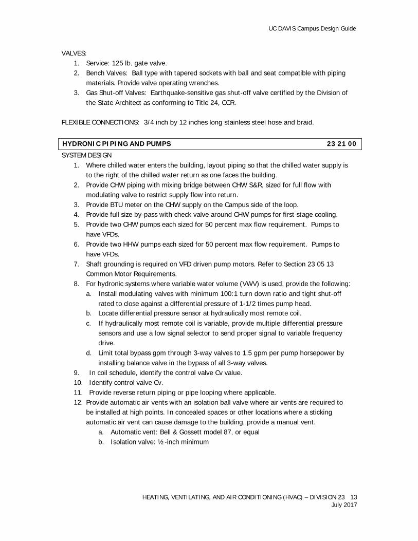
SYSTEM DESIGN
1. Where chilled water enters the building, layout piping so that the chilled water supply is to the right of the chilled water return as one faces the building.
2. Provide CHW piping with mixing bridge between CHW S&R, sized for full flow with modulating valve to restrict supply flow into return.
3. Provide BTU meter on the CHW supply on the Campus side of the loop. 4. Provide full size by-pass with check valve around CHW pumps for first stage cooling. 5. Provide two CHW pumps each sized for 50 percent max flow requirement. Pumps to
have VFDs. 6. Provide two HHW pumps each sized for 50 percent max flow requirement. Pumps to
have VFDs. 7. Shaft grounding is required on VFD driven pump motors. Refer to Section 23 05 13
Common Motor Requirements. 8. For hydronic systems where variable water volume (VWV) is used, provide the following:
a. Install modulating valves with minimum 100:1 turn down ratio and tight shut-off rated to close against a differential pressure of 1-1/2 times pump head.
b. Locate differential pressure sensor at hydraulically most remote coil. c. If hydraulically most remote coil is variable, provide multiple differential pressure
sensors and use a low signal selector to send proper signal to variable frequency drive.
d. Limit total bypass gpm through 3-way valves to 1.5 gpm per pump horsepower by installing balance valve in the bypass of all 3-way valves.
9. In coil schedule, identify the control valve Cv value. 10. Identify control valve Cv. 11. Provide reverse return piping or pipe looping where applicable. 12. Provide automatic air vents with an isolation ball valve where air vents are required to
be installed at high points. In concealed spaces or other locations where a sticking automatic air vent can cause damage to the building, provide a manual vent.
a. Automatic vent: Bell & Gossett model 87, or equal b. Isolation valve: ½-inch minimum
HYDRONIC PIPING AND PUMPS 23 21 00
UC DAVIS Campus Design Guide
HEATING, VENTILATING, AND AIR CONDITIONING (HVAC) – DIVISION 23 14 July 2017
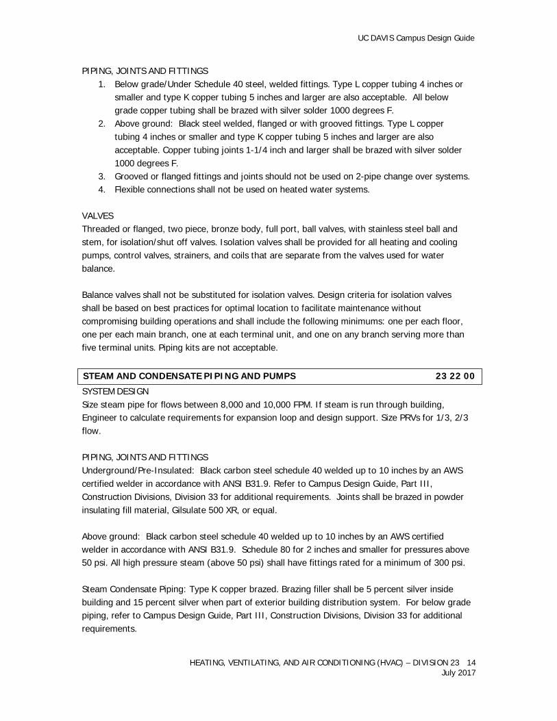
PIPING, JOINTS AND FITTINGS 1. Below grade/Under Schedule 40 steel, welded fittings. Type L copper tubing 4 inches or
smaller and type K copper tubing 5 inches and larger are also acceptable. All below grade copper tubing shall be brazed with silver solder 1000 degrees F.
2. Above ground: Black steel welded, flanged or with grooved fittings. Type L copper tubing 4 inches or smaller and type K copper tubing 5 inches and larger are also acceptable. Copper tubing joints 1-1/4 inch and larger shall be brazed with silver solder 1000 degrees F.
3. Grooved or flanged fittings and joints should not be used on 2-pipe change over systems. 4. Flexible connections shall not be used on heated water systems.
VALVES Threaded or flanged, two piece, bronze body, full port, ball valves, with stainless steel ball and stem, for isolation/shut off valves. Isolation valves shall be provided for all heating and cooling pumps, control valves, strainers, and coils that are separate from the valves used for water balance.
Balance valves shall not be substituted for isolation valves. Design criteria for isolation valves shall be based on best practices for optimal location to facilitate maintenance without compromising building operations and shall include the following minimums: one per each floor, one per each main branch, one at each terminal unit, and one on any branch serving more than five terminal units. Piping kits are not acceptable.
SYSTEM DESIGN Size steam pipe for flows between 8,000 and 10,000 FPM. If steam is run through building, Engineer to calculate requirements for expansion loop and design support. Size PRVs for 1/3, 2/3 flow.
PIPING, JOINTS AND FITTINGS Underground/Pre-Insulated: Black carbon steel schedule 40 welded up to 10 inches by an AWS certified welder in accordance with ANSI B31.9. Refer to Campus Design Guide, Part III, Construction Divisions, Division 33 for additional requirements. Joints shall be brazed in powder insulating fill material, Gilsulate 500 XR, or equal.
Above ground: Black carbon steel schedule 40 welded up to 10 inches by an AWS certified welder in accordance with ANSI B31.9. Schedule 80 for 2 inches and smaller for pressures above 50 psi. All high pressure steam (above 50 psi) shall have fittings rated for a minimum of 300 psi.
Steam Condensate Piping: Type K copper brazed. Brazing filler shall be 5 percent silver inside building and 15 percent silver when part of exterior building distribution system. For below grade piping, refer to Campus Design Guide, Part III, Construction Divisions, Division 33 for additional requirements.
STEAM AND CONDENSATE PIPING AND PUMPS 23 22 00
UC DAVIS Campus Design Guide
HEATING, VENTILATING, AND AIR CONDITIONING (HVAC) – DIVISION 23 15 July 2017
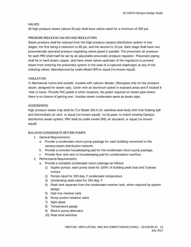
VALVES All high pressure steam (above 50 psi) shall have valves rated for a minimum of 300 psi.
PRESSURE REDUCING VALVES AND REGULATORS Steam pressure shall be reduced from the high pressure campus distribution system in two stages, the first being a reduction to 80 psi, and the second to 15 psi. Each stage shall have two pneumatically operated pressure regulating valves piped in parallel. The pneumatic air pressure for each PRV shall itself be set by an adjustable pneumatic pressure regulator. Pneumatic piping shall be in hard-drawn copper, and have check valves upstream of the regulators to prevent steam from entering the pneumatic system in the case of a ruptured diaphragm at any of the reducing valves. Manufactured by Leslie Model GPS or equal (no known equal).
INSULATION In Mechanical rooms and outside, insulate with calcium silicate, (fiberglass only on low pressure steam, designed for steam use). Cover with an aluminum jacket in exposed areas and if located 8 -feet or lower. Provide PVC jacket in other locations. No jacket required on steam pipe where there is no chance of getting wet. Insulate steam condensate same as steam pipe.
ACCESSORIES High pressure steam trap shall be TLV Model J3S-X-10, stainless steel body with free floating ball and thermostatic air vent, or equal (no known equal); no by-pass, to match existing Campus distribution steam system. PRV shall be Leslie model GPS, air actuated, or equal (no known equal).
BUILDING CONDENSATE RETURN PUMPS
1. General Requirements: a. Provide a condensate return pump package for each building connected to the
campus steam distribution network. b. Provide a concrete housekeeping pad for the condensate return pump package. c. Provide floor sink next to housekeeping pad for condensation overflow.
2. Performance Requirements: a. Provide a complete condensate return package as follows:
1) Duplex pumps; each pump sized for 100% of building peak load and 3-phase motors
2) Pumps rated for 200 deg. F condensate temperature 3) Condensing seals rated for 250 deg. F 4) Flash tank separate from the condensate receiver tank, when required by system
design 5) Cast iron receiver tank 6) Pump suction isolation valve 7) Sight glass 8) Temperature gauge 9) Electric pump alternator 10) Float level switches
UC DAVIS Campus Design Guide
HEATING, VENTILATING, AND AIR CONDITIONING (HVAC) – DIVISION 23 16 July 2017
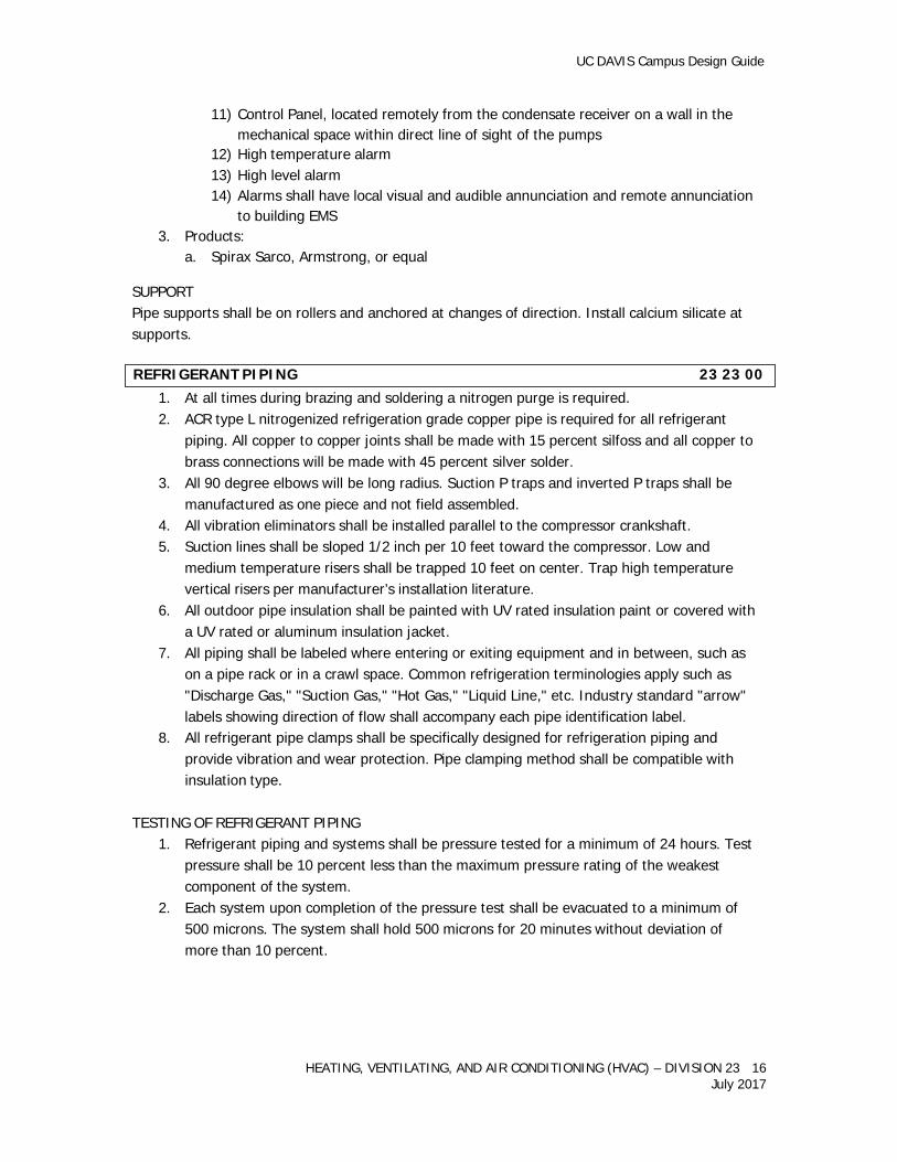
11) Control Panel, located remotely from the condensate receiver on a wall in the mechanical space within direct line of sight of the pumps
12) High temperature alarm 13) High level alarm 14) Alarms shall have local visual and audible annunciation and remote annunciation
to building EMS 3. Products:
a. Spirax Sarco, Armstrong, or equal
SUPPORT Pipe supports shall be on rollers and anchored at changes of direction. Install calcium silicate at supports.
1. At all times during brazing and soldering a nitrogen purge is required. 2. ACR type L nitrogenized refrigeration grade copper pipe is required for all refrigerant
piping. All copper to copper joints shall be made with 15 percent silfoss and all copper to brass connections will be made with 45 percent silver solder.
3. All 90 degree elbows will be long radius. Suction P traps and inverted P traps shall be manufactured as one piece and not field assembled.
4. All vibration eliminators shall be installed parallel to the compressor crankshaft. 5. Suction lines shall be sloped 1/2 inch per 10 feet toward the compressor. Low and
medium temperature risers shall be trapped 10 feet on center. Trap high temperature vertical risers per manufacturer’s installation literature.
6. All outdoor pipe insulation shall be painted with UV rated insulation paint or covered with a UV rated or aluminum insulation jacket.
7. All piping shall be labeled where entering or exiting equipment and in between, such as on a pipe rack or in a crawl space. Common refrigeration terminologies apply such as "Discharge Gas," "Suction Gas," "Hot Gas," "Liquid Line," etc. Industry standard "arrow" labels showing direction of flow shall accompany each pipe identification label.
8. All refrigerant pipe clamps shall be specifically designed for refrigeration piping and provide vibration and wear protection. Pipe clamping method shall be compatible with insulation type.
TESTING OF REFRIGERANT PIPING
1. Refrigerant piping and systems shall be pressure tested for a minimum of 24 hours. Test pressure shall be 10 percent less than the maximum pressure rating of the weakest component of the system.
2. Each system upon completion of the pressure test shall be evacuated to a minimum of 500 microns. The system shall hold 500 microns for 20 minutes without deviation of more than 10 percent.
REFRIGERANT PIPING 23 23 00
UC DAVIS Campus Design Guide
HEATING, VENTILATING, AND AIR CONDITIONING (HVAC) – DIVISION 23 17 July 2017
SYSTEMS DESIGN
1. Indicate on the drawings or specifications that low pressure loss duct fittings shall be installed per Sheet Metal and Air Conditioning Contractors National Association (SMACNA) (see Section 2: Design for Energy Efficiency and SMACNA HVAC Systems Duct Design).
2. Specify appropriate SMACNA duct air leakage class (see SMACNA HVAC Air Duct Leakage Test Manual and SMACNA Technical Paper on Duct Leakage. Identify duct pressure classes on the ductwork plans, such as 1/2, 1, 2 etc., inside a triangle. Refer to SMACNA HVAC Duct Construction Standards, Figure 1-1. Require duct leakage testing for all ducts rated at two (2) inches of water and greater.
3. All return air shall be ducted.
FANS, MOTORS, AND DRIVES: 1. Fans shall be licensed to bear the AMCA ratings seal. Fans shall be tested for air and
sound performance in accordance with the appropriate AMCA standard in an AMCA accredited laboratory.
2. The design horsepower rating of each drive shall be at least 1.5 times the nameplate rating of the motor. Proper allowances for sheave diameters, speed ration, arcs of contact and belt length shall be followed in meeting the design horsepower of the drive.
3. All variable speed drives shall be selected to allow an increase or decrease of minimum of 10 percent of design fan speed.
4. Motor shaft grounding: See Division 23 05 13 Common Motor Requirements. 5. Motors over 15 HP: Adjustable sheaves shall be removed and replaced with fixed
diameter sheaves prior to final air balancing.
SHAFTS AND BEARINGS: 1. Fan shaft shall be ground and polished solid steel with an anti-corrosive coating. 2. Bearing shall be selected for a minimum L-10 life in excess of 100,000 hours at maximum
cataloged operating speed. Bearings shall be locked to the shaft concentrically without marring or burring the shaft.
3. All shaft bearings shall have extended lube lines with zerk fittings. Extended lube lines shall be UV resistant where exposed to the sun.
SHEAVES:
1. Sheaves shall be cast or fabricated, bored to size or bushed with fully split tapered bushings to fit properly on the shafts.
DUCTWORK Use low pressure drop duct design. Use round duct wherever space permits. Only use flex duct to connect ducts to terminal diffusers, registers and grilles. Maximum length shall be seven (7) feet. The throat radius of all bends shall be 1-1/2 times the width of the duct wherever possible and in no case shall the throat radius be less than one width of the branch duct. Provide square elbows double thickness turning vanes where space does not permit the above radius and where square elbows are shown. The slopes of transitions shall be approximately one to five, and no abrupt
HVAC AIR DISTRIBUTION 23 30 00
UC DAVIS Campus Design Guide
HEATING, VENTILATING, AND AIR CONDITIONING (HVAC) – DIVISION 23 18 July 2017
changes or offsets of any kind in the duct system shall be permitted. Limit pressure drop to 0.07 inches H2O per 100 feet. Insulation shall exceed latest CCR-Title 24, Part 6.
Provide drive slip or equivalent flat seams for ducts exposed in the conditioned space or where necessary due to space limitations. On ducts over 48 inches wide, provide standard reinforcing on inside of duct. Run-outs to grilles, registers or diffusers on exposed ductwork shall be the same size as the outer perimeter of the flange on the grille, register or diffuser. Provide flexible connections on inlet and outlet of each fan. Seal all seams around fan and coil housings airtight with appropriate sealing compound.
DAMPERS Motor-operated, opposed blade type shall be galvanized iron with nylon bearings, interlocking edges to prevent leakage. Dampers shall have replaceable blade seals and stops for minimum air leakage. Blades shall be 16-gauge minimum, 10 inches maximum width with welded channel iron frame. Frame shall be sealed airtight to ductwork. Dampers with both dimensions less than 18 inches may have strap iron frames. Dampers exposed to the weather shall be weatherproof and made of corrosion proof materials.
SMOKE DETECTORS IN DUCTWORK For additional information, refer to the University’s Standard Specification Section 28 31 00, Fire Detection and Alarm.
Layout ductwork and locate duct smoke detectors to ensure clearance is available upstream and downstream of detectors pursuant to detector manufacturer’s requirements. Duct detectors shall be compatible with the building’s Fire Alarm System and shall be approved by the Fire Marshal of record. Duct detectors shall be accessible for testing and maintenance.
VAV AND CV BOXES The maximum air pressure drop (PD) of a bare box shall be 0.07 inches. For 1 row coil add 0.10 inches max. PD and for 2 row coil add 0.15 inches to 0.20 inches PD. For VAV systems, unless calculations indicate otherwise, set minimum air flow for cooling and for heating to 40 percent of the maximum air flow value.
GRILLES, REGISTERS AND LOUVERS Provide all outlets with gaskets to minimize the streaking of the walls or ceilings due to leakage.
Refer to Campus Design Guide, Part III Construction Divisions, Division 11 on Laboratory Equipment for information on fume hood construction. Refer to Section 23 09 10 for Laboratory Airflow Control Requirements.
LABORATORY HOOD EXHAUST FANS
1. Fan type shall be carefully engineered and selected to meet or exceed its intended usage.
FUME HOODS 23 38 16
UC DAVIS Campus Design Guide
HEATING, VENTILATING, AND AIR CONDITIONING (HVAC) – DIVISION 23 19 July 2017
2. Fan assemblies shall be constructed with corrosion resistant materials engineered for the intended application.
3. Fan shall be licensed and bear the AMCA ratings seal. Fans shall be tested for air and sound performance in accordance with the appropriate AMCA standard in an AMCA accredited laboratory.
4. Each fan shall be vibration tested as an assembly before shipping in accordance with AMCA 204-05.
5. Unit shall bear an engraved nameplate. Nameplate shall indicate design CFM, static pressure, and maximum fan RPM.
6. Unit fasteners exposed to corrosive airstream shall be of stainless steel construction. 7. Provide fan curves for each fan at the specified operation point, with flow, static
pressure, and horsepower clearly plotted.
FANS, MOTORS, AND DRIVES: 1. Motors shall be premium efficiency, standard NEMA frame, 1800 or 3600 RPM, TEFC with
a 1.15 service factor. 2. Motor shaft grounding: See Division23 05 13 Common Motor Requirements. 3. Motor maintenance shall be accomplished without fan impeller removal or requiring
maintenance personnel to access the contaminated exhaust components. Belt drive configuration (if equipped) shall be AMCA arrangement 1, 9, or 10. High plume arrangement 9 fans shall feature a bifurcated housing with the motor, belt drive (if equipped), and bearings located outside of the contaminated airstream. Direct drive arrangement 4, or direct drive arrangements requiring access and handling of hazardous and contaminated fan components for motor replacement are not acceptable.
4. Drive belts and sheaves shall be sized for 200percent of the fan operating brake horsepower, and shall be readily and easily accessible for service. Drive shall consist of a minimum of two belts under all circumstances.
5. Fan shaft bearings shall be Air Handling Quality, ball or roller pillow block type and be sized for an L-10 life of no less than 200,000 hours for high plume fans and critical applications, and L-10 100,000 hours for all others. Bearings shall be fixed to the fan shaft using concentric mounting locking collars, which reduce vibration, increase service life, and improve serviceability. Bearings that use set screws shall not be acceptable.
6. All shaft bearings shall have extended lube lines with zerk fittings. Extended lube lines shall be UV resistant.
A. General Requirements:
1. Heating hot water boilers shall be certified as compliant with Rule 1146.2 of the current South Coast Air Quality Management District (SCAQMD)
2. Boilers shall meet local county air quality management district standards for emissions. Boiler(s) that have a maximum input of 1,000,000 BTU/H or greater will trigger air permitting with Yolo-Solano Air Quality Management District (Y-S AQMD). Coordinate permit with University’s Representative if applicable.
3. Heating hot water boilers shall be installed with BACnet interface to the Campus energy management system with external set point reset.
4. Flow meters: Boiler systems shall have a fuel flow meter that provides a local indication of flow rate and a non-resettable, totalizing measure of gaseous fuel flow measured in cubic feet. The meter(s) shall have a network interface for the buildings energy management system.
B. Performance Criteria:
1. Heating hot water boilers shall have a maximum input of 3,000,000 BTU/H.
HEATING HOT WATER BOILERS 23 52 00
UC DAVIS Campus Design Guide
HEATING, VENTILATING, AND AIR CONDITIONING (HVAC) – DIVISION 23 20 July 2017
Heating hot water boilers over 500,000 BTU/H input shall meet a minimum thermal efficiency of 92% as rated by the Institute of Boiler and Radiator Manufactures (IBR),Air-Conditioning, Heating, and Refrigeration Institute (AHRI), or comparable certification authority.
2. Heating hot water boilers shall have a minimum turndown ratio of 3.5:1. 3. Manufacturer:
a. Shall have a minimum of twenty existing successful installations of the same model; five of which must be in California.
b. The heating hot water boiler manufacturer shall review the boiler for proper installation and shall warranty the boiler for parts and labor for five years after the boiler has been accepted as complete by the University’s Representative.
c. The manufacturer shall include two site visits to the site after the University’s acceptance to confirm the boiler is operating as commissioned. 1) The first visit shall be 12 months after the start of the warranty period. 2) The second visit shall be 23 months after the start of the warranty period.
C. Installation Requirements:
1. The contractor shall have a minimum of five heating hot water boiler installations in California.
2. Boiler feed water shall be treated to prevent scaling from hard water. Initial fill shall be with softened water.
Electronic ignition. Heaters over 100,000 btu shall be hard piped to their external shut off valve. Fan and blower motors shall be wired to allow cooling of the heat exchanger upon cycling on temperature.
IDENTIFICATION
1. Refrigerant and compressor oil type shall be clearly marked using nameplates on each unit.
2. The initial refrigerant charge shall be clearly listed using nameplates on each condensing unit.
3. A permanent nameplate shall be installed on both indoor and outdoor equipment stating the room number the equipment is serving (or located within) and identify each piece of equipment clearly.
ELECTRICAL
1. All Semi Hermetic compressor motors less than 1 horsepower shall have single phase characteristics.
2. All motors over 1.5 horsepower shall have three phase characteristics. 3. Three phase equipment should incorporate a phase monitor. 4. Each refrigeration system shall be served by its own dedicated circuit breaker and
disconnect means.
REFRIGERATION TEMPERATURE CONTROL Refer to Campus Standards & Design Guide, Part IV, Standard Specifications Section 13 21 00 for Controlled Environmental Rooms Requirements.
FUEL-FIRED HEATERS 23 55 00
MECHANICAL REFRIGERATION 23 60 00
UC DAVIS Campus Design Guide
HEATING, VENTILATING, AND AIR CONDITIONING (HVAC) – DIVISION 23 21 July 2017
Systems that can tolerate more than + or -2 degrees F deviation from set-point shall incorporate simplified control systems utilizing industry standard practices for control of refrigeration equipment.
Standard "off the shelf" readily available temperature, operating and limit controls shall be utilized whenever possible. Avoid electro-mechanical remote bulb controls. In their place, use electronic remote sensing controls such as Ranco, Honeywell, Johnson, or equal.
MICROPROCESSOR BASED CONTROLLERS (when necessary to achieve the design temperature requirements)
1. Microprocessor based refrigeration system controllers shall be fully adjustable, field programmable, electronic digital type controllers.
2. The controller shall be designed specifically for the control of compressors, condensers and refrigeration equipment.
3. The controller shall have the ability to provide sensor and transducer control. 4. The controllers shall include a keypad interface with easy to read display, and shall not
require the use of a computer to program. 5. PLC controllers are not acceptable unless they are a component of a pre-packaged
factory manufactured and engineered refrigeration system. LOCAL/REMOTE ALARM INTERFACE (when required)
1. Consideration shall be given to local and remote alarming. 2. A separate temperature alarm with Hi/Lo capability is required. 3. Control shall be capable of remote and local alarming. 4. Form C dry contacts N/O and N/C required. 5. Alarm sensor should be placed next to operating control sensor. 6. Control shall feature user selectable time delay feature. 7. Control adjustment shall be lockable to prevent tampering. 8. Control shall feature an adjustable offset of displayed temperature for calibration
purposes. CONDENSING UNITS
1. The refrigeration system shall be the standard product of a single manufacturer and shall be cataloged as systems, complete with system capacities. All components including controls and accessories shall be furnished by the system manufacturer and shall include a fully piped air-cooled condensing unit (as described below), evaporator (as described below), thermostatic expansion valve, liquid line drier, room thermostat, liquid line solenoid valve, suction line filter, etc.
2. Condensing units shall include motor-compressor, condenser, receiver, electrical control panel and all defrost components completely assembled on a steel rack, piped, wired, run-in and tested by the manufacturer. The motor compressors shall be semi hermetic with inherent 3-leg overload protection.
3. Air-cooled condensing units not located outside the building shall be located in a controlled temperature room. All systems with outdoor condensers or condensing units
UC DAVIS Campus Design Guide
HEATING, VENTILATING, AND AIR CONDITIONING (HVAC) – DIVISION 23 22 July 2017
shall be provided with low ambient controls including a crankcase heater and a condenser fan control.
4. Condensing unit noise shall not exceed 78 decibels tested in accordance with ARI standards. Condensing units shall carry a 5 year compressor warranty.
5. All refrigeration pressure relief lines shall be piped to a location outside the building 20 or more feet from an intake opening, operable window, etc.
6. A refrigerant receiver is required on all pump down systems. 7. All refrigeration systems shall be provided with a high and low pressure switch. 8. Thermal expansion valve systems are required on systems larger than ½ horsepower.
All thermal expansion valve systems will include a liquid moisture indicator. Expansion valve bulbs will be secured with brass straps and be insulated.
9. Liquid filter driers shall be included on all systems. Removable suction filter driers shall be utilized when needed to clean up large systems during initial break in period. Suction filter driers or cores shall be removed after minimum 48 hours of run time.
10. Low temperature refrigeration systems shall include a suction accumulator and will operate as a pump down system.
11. A complete wiring and control diagram will be permanently affixed in a waterproof container to the inside of each compressor control panel.
12. Equipment charged in the field shall have a permanent label affixed to the condensing unit stating the refrigerant type, oil type, and operating refrigerant charge in pounds.
13. An oil failure control will be required on all semi-hermetic compressors with an oil pump. 14. Hot gas bypass valves will be installed with Schrader valve access and isolation ball
valves. 15. All low temperature refrigeration systems shall have electric defrost. 16. All freezer condensate drain lines shall be insulated and shall include electrical heat
tracing from a separate circuit.
EVAPORATORS 1. Units shall have direct expansion cooling coils mounted in aluminum casing and be
horizontally supported from the ceiling. 2. Coil shall have copper tubes hydraulically expanded into aluminum fins. Pitch coils in
casing to provide drainage. 3. Evaporator drain will be provided with a trap outside of the refrigerated areas. 4. Drains will include a clean out tee and a pipe union and will not be reduced from the
manufactured provided line size. 5. Freezer drains will include a drain line heater and rubber insulation 6. Fan motors shall have built-in thermal over-load protection. 7. Systems having electric defrost shall include an evaporator fan thermostat and defrost
termination control.
Packaged Water Chillers: Compressor(s) shall carry a 5 year manufacturer’s warranty. Manufacturer’s service clearances shall be met, refer to Part II Design Requirements for additional access requirements.
PACKAGED WATER CHILLERS 23 64 00
UC DAVIS Campus Design Guide
HEATING, VENTILATING, AND AIR CONDITIONING (HVAC) – DIVISION 23 23 July 2017
Draw through air handling units are required. Air handlers 10,000 cfm and larger including coil ends that are exposed to outside air conditions to have insulated casings to a minimum of R-8. If exposed to return air conditions R-4 is acceptable. Provide a variable frequency drive (VFD) for VAV systems and motors over 10 HP.
Systems with heating and cooling coils shall be configured with the heating coil receiving the incoming air before the cooling coil. For chilled water systems connected to the central plant, provide a minimum chilled water delta T of 20 degrees for all AHUs.
For heating hot water system, provide a system delta T of 40 degrees or higher.
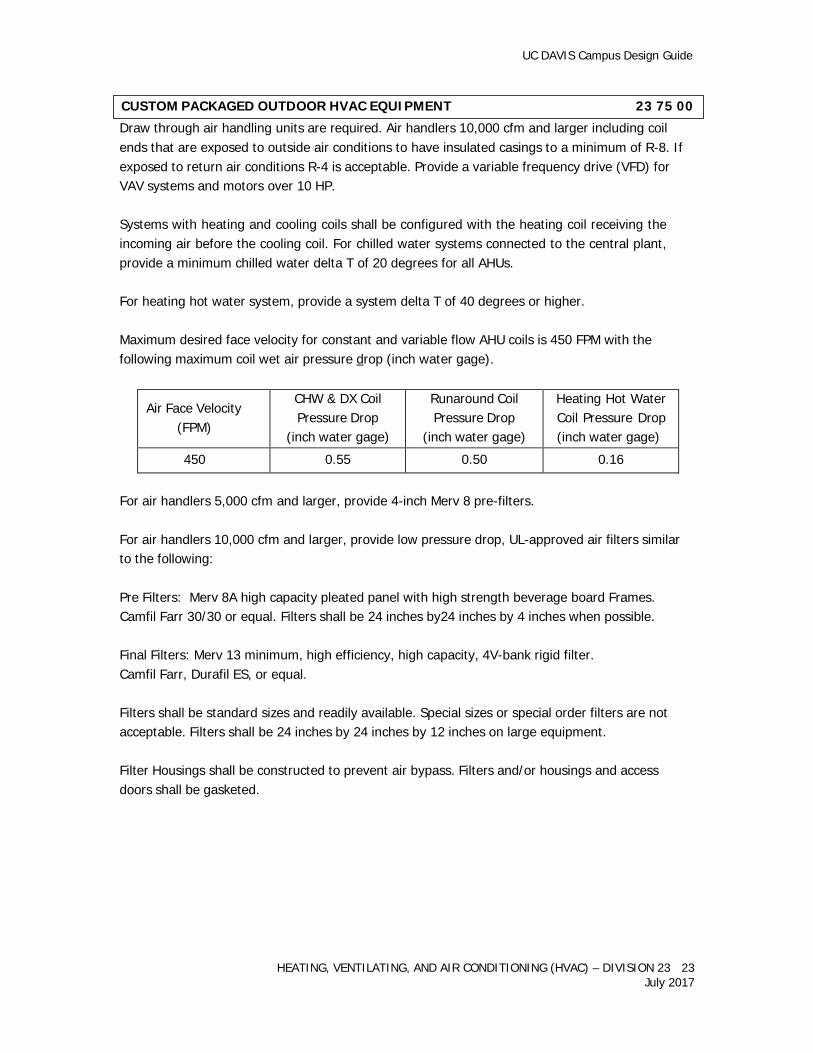
Maximum desired face velocity for constant and variable flow AHU coils is 450 FPM with the following maximum coil wet air pressure drop (inch water gage).
Air Face Velocity
(FPM)
CHW & DX Coil Pressure Drop
(inch water gage)
Runaround Coil Pressure Drop
(inch water gage)
Heating Hot Water Coil Pressure Drop (inch water gage)
450 0.55 0.50 0.16
For air handlers 5,000 cfm and larger, provide 4-inch Merv 8 pre-filters.
For air handlers 10,000 cfm and larger, provide low pressure drop, UL-approved air filters similar to the following:
Pre Filters: Merv 8A high capacity pleated panel with high strength beverage board Frames. Camfil Farr 30/30 or equal. Filters shall be 24 inches by24 inches by 4 inches when possible.
Final Filters: Merv 13 minimum, high efficiency, high capacity, 4V-bank rigid filter. Camfil Farr, Durafil ES, or equal.
Filters shall be standard sizes and readily available. Special sizes or special order filters are not acceptable. Filters shall be 24 inches by 24 inches by 12 inches on large equipment.
Filter Housings shall be constructed to prevent air bypass. Filters and/or housings and access doors shall be gasketed.
CUSTOM PACKAGED OUTDOOR HVAC EQUIPMENT 23 75 00
UC DAVIS Campus Design Guide
HEATING, VENTILATING, AND AIR CONDITIONING (HVAC) – DIVISION 23 24 July 2017
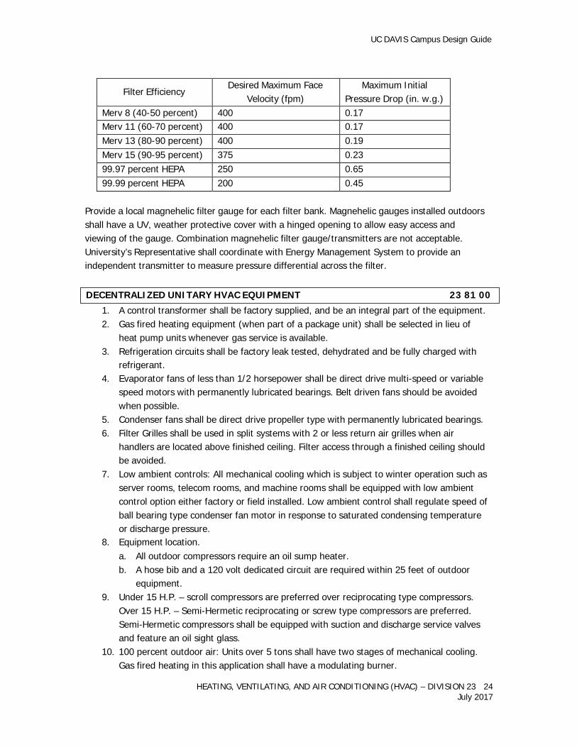
Filter Efficiency Desired Maximum Face Velocity (fpm)
Maximum Initial Pressure Drop (in. w.g.)
Merv 8 (40-50 percent) 400 0.17 Merv 11 (60-70 percent) 400 0.17 Merv 13 (80-90 percent) 400 0.19 Merv 15 (90-95 percent) 375 0.23 99.97 percent HEPA 250 0.65 99.99 percent HEPA 200 0.45
Provide a local magnehelic filter gauge for each filter bank. Magnehelic gauges installed outdoors shall have a UV, weather protective cover with a hinged opening to allow easy access and viewing of the gauge. Combination magnehelic filter gauge/transmitters are not acceptable. University’s Representative shall coordinate with Energy Management System to provide an independent transmitter to measure pressure differential across the filter.
1. A control transformer shall be factory supplied, and be an integral part of the equipment. 2. Gas fired heating equipment (when part of a package unit) shall be selected in lieu of
heat pump units whenever gas service is available. 3. Refrigeration circuits shall be factory leak tested, dehydrated and be fully charged with
refrigerant. 4. Evaporator fans of less than 1/2 horsepower shall be direct drive multi-speed or variable
speed motors with permanently lubricated bearings. Belt driven fans should be avoided when possible.
5. Condenser fans shall be direct drive propeller type with permanently lubricated bearings. 6. Filter Grilles shall be used in split systems with 2 or less return air grilles when air
handlers are located above finished ceiling. Filter access through a finished ceiling should be avoided.
7. Low ambient controls: All mechanical cooling which is subject to winter operation such as server rooms, telecom rooms, and machine rooms shall be equipped with low ambient control option either factory or field installed. Low ambient control shall regulate speed of ball bearing type condenser fan motor in response to saturated condensing temperature or discharge pressure.
8. Equipment location. a. All outdoor compressors require an oil sump heater. b. A hose bib and a 120 volt dedicated circuit are required within 25 feet of outdoor
equipment. 9. Under 15 H.P. – scroll compressors are preferred over reciprocating type compressors.
Over 15 H.P. – Semi-Hermetic reciprocating or screw type compressors are preferred. Semi-Hermetic compressors shall be equipped with suction and discharge service valves and feature an oil sight glass.
10. 100 percent outdoor air: Units over 5 tons shall have two stages of mechanical cooling. Gas fired heating in this application shall have a modulating burner.
DECENTRALIZED UNITARY HVAC EQUIPMENT 23 81 00
UC DAVIS Campus Design Guide
HEATING, VENTILATING, AND AIR CONDITIONING (HVAC) – DIVISION 23 25 July 2017
11. All refrigeration circuits shall be equipped with high and low pressure safety pressure switches.
12. On units with belt drive evaporator fans, an air proving differential pressure switch shall be provided and wired to disable the mechanical cooling upon loss of air flow.
13. All compressors shall be mounted on vibration isolators. 14. Wall Mounted Thermostats.
Refer to Standard Energy Management section. Required Control Features: a. Multistage programmable 7 day. b. Memory retention after loss of power. c. No batteries required. d. 2 stage heat and cool. e. Automatic changeover. f. Heat pump compatible. g. Dual set point with adjustable dead-band. h. Large alphanumeric display backlit. i. Easy programming. j. Display either degrees F or C. k. Locking keypad. l. 5 minute short cycle protection. m. Soft start compatible. n. Remote sensor compatible.
15. Provide 18/8 conductor thermostat cable installed in a dedicated conduit.
1. Dedicated Unitary special purpose computer server room air conditioners shall be used. 2. Avoid belt driven fans and blowers on systems 5 tons or less. 3. Equipment shall incorporate dry contacts for remote alarm monitoring. 4. Server room application may require humidification, de-humidification and re-heat
capability. Where required, ultrasonic or infrared type humidifier preferred. Canister type steam generators should be avoided if using Campus industrial cold water as the make- up source.
1. Variable Refrigerant Flow (VRF) Split Systems:
a. Manufacturers: Mitsubishi, Fujitsu, or equal. b. Installers: Shall be certified by the manufacturer. c. Warranty: Manufacturer 5-year warranty for equipment and parts. d. Thermostats: Shall feature auto-changeover and separate heating/cooling setpoints. e. Final field refrigerant charge shall be clearly identified on each outdoor unit.
1. Heaters over 100,000 BTUH shall be hard piped to their external shut off valve. 2. Fan and blower motors shall be wired to allow cooling of the heat exchanger upon
cycling on temperature.
COMPUTER SERVER ROOM AIR CONDITIONERS 23 81 23
SPLIT SYSTEM AIR CONDITIONERS 23 81 26
CONVECTION HEATING AND COOLING UNITS 23 82 00
UC DAVIS Campus Design Guide
HEATING, VENTILATING, AND AIR CONDITIONING (HVAC) – DIVISION 23 26 July 2017
3. A drip leg shall be installed on gas supply piping at each appliance. 4. Gas fired unit heaters installed indoors shall have forced draft combustion. 5. Gas fired equipment installed in a dirty, dusty or otherwise contaminated location shall
feature separated combustion. 6. Gas fired equipment installed in a negative pressure environment shall feature separated
combustion. 7. Gas fired equipment heating 100 percent outside air or heating air at an inlet air
temperature below 40 degrees F shall feature stainless steel burners and heat exchangers.
8. Boilers, steam generators and process heaters that trigger permitting shall have a non- resettable, totalizing gaseous fuel flow meter that measures the quantity (in cubic feet) of fuel combusted by the unit(s). Comply with California Health and Safety Code, Division 26 for local air quality permitting requirements.
The Main Mechanical Room for the project should be separated into two rooms. One room, a “hot” room would contain all heat generating equipment such as heat exchangers, etc. The second “cool” room shall contain the pumps, VFDs and other heat sensitive electronics.
The “hot” room should be located to allow natural ventilation through wall louvers. It should be conditioned with a hydronic fan coil that uses 100 percent outside air for the first stage of cooling. The “hot” room set point shall be 90 degrees F with a local override to 78 degrees F. If an occupied space is to be located above this room insulation shall be applied to the overhead deck to not allow the temperature of this room to effect the space above.
The “cool” pump room shall be conditioned via a separate fan coil to maintain 78 degrees F for the electronic equipment.
If mechanical room contains equipment containing refrigerant, careful consideration shall be given to refrigerant leak monitoring, leak alarm systems, and emergency exhausting mandatory requirements per code, EPA and Cal/ EPA requirements.
The final size and layout of the mechanical rooms is dependent on the final accepted mechanical system and required equipment. All mechanical rooms should be sized adequately to allow, not just code compliant clearances, but manufacturers required service clearances for maintenance staff. Review and coordinate the size, design and layout of the mechanical rooms with University’s Representative.
End of Division 23
BUILDING MECHANICAL ROOMS 23 90 00