Embed Size (px)
Citation preview

Ventilated Workstation Manual for AFB Smear Microscopy
M A N U FA C T U R I N G , VA L I D AT I O N ,
A N D U S E R G U I D E
A VA L I D AT E D , I N E X P E N S I V E
L A B O R AT O RY W O R K S TAT I O N
A S S O C I A T I O N O F
P U B L I C H E A LT H L A B O R A T O R I E S


PrefaceAFB-smear microscopy is still the primary test to provide rapid detection, diagnosis, and monitoring of the treatment of
tuberculosis in much of the world, especially in those countries with the highest burden of disease. An important component
of effective TB control programs is making AFB-smear microscopy accessible to the population so that symptomatic persons
can be rapidly diagnosed for treatment, and to prevent transmission in the community. There are tens of thousands of smear
microscopy centers around the world and many are located in small clinics or hospitals. Preparation of the smear directly from
sputum specimens is usually performed on the open laboratory bench. With good microbiological techniques and adequate
ventilation, the risk of infection is considered to be minimal. However, quality of results may be compromised when laboratory
workers reduce the level of manipulation required to obtain a high quality smear out of concern for the generation of
potentially infectious aerosols.
AFB microscopy laboratories require adequate ventilation to minimize the occupational risk of infection. However, this is
difficult to achieve in many settings where facilities have limited airflow; where climate limits the use of open windows; and
where mixing fans may be ineffective in maintaining directional airflow. Almost 35 years ago, Smithwick and Kubica at the
U.S. CDC provided drawings and directions for construction of an “inexpensive Class I negative pressure BSC” intended
to be used for handling a range of microbiological specimens (Smithwick, unpublished data). Using these and other plans
developed by public or commercial entities, several exhaust cabinets of various designs have been fabricated and are found
in use globally in TB and other laboratories. However, many of these exhaust cabinets have not been validated against
performance specifications and can pose increased risk due to a false sense of safety. Commercially produced biosafety
cabinetry or microbiological safety cabinets built to exacting performance standards are available but not affordable or
appropriate for this particular purpose, and validation and maintenance are problematic in resource-limited laboratory
systems. There is broad agreement among laboratory experts of the need for an inexpensive ventilated cabinet that can be
produced according to validated specifications and made available as an option for technicians preparing AFB smears.
This guide provides specifications for the manufacture of a ventilated workstation (VWS) that has been validated1. The
VWS is a partially-enclosed workspace from which air is drawn inward, away from the user and exhausted outside of the
laboratory. The purpose of the VWS is to provide a safe work environment when preparing sputum smears for AFB staining
or sample manipulations that inactivate sputum specimens for automated molecular testing systems e.g., GeneXpert
MTB/RIF Assay from Cepheid (Padmapriya et al, 2010).
This Guide should not be interpreted as new guidance on risk related to the preparation of AFB smears, but rather another
option for providing a safe laboratory work environment. The VWS is inexpensive to build and requires minimal maintenance.
The project to design, test, and produce the VWS and VWS guide was conceived and approved through the Global Laboratory
Initiative (GLI) Working Group of the Stop TB Partnership, WHO, The Union, FIND, CDC, and partner organizations. This
project was funded by USAID and CDC through a cooperative agreement with APHL. We are most grateful for the engineers
and experts from Germfree and The Baker Company who freely contributed their facilities and expertise to develop prototypes,
conduct validations, and provide design drawings and validation reports for this guidance document. The goal of this guidance
document is to provide countries with public domain specifications to allow local manufacture of VWSs and encourage
regional manufacturers to develop these products for a potential global market of thousands of smear microscopy centers.
John Ridderhof, Pawan Angra, and Ralph Timperi
VENTILATED WORKSTATION MANUAL FOR AFB SMEAR MICROSCOPY | 1
1. See validation report in section 5.4.

AcknowledgementsThe Ventilated Workstation (VWS) project is a combined effort on the part of many organizations and individuals who
have contributed to the content and development of this guidance document. We acknowledge the members of the
initial workgroup that convened in Atlanta, USA in September 2009 and other key individuals who readily volunteered
to contribute time and materials for the development of this document. We sincerely appreciate the contributions of
Keith Landy from Germfree and David Eagleson from The Baker Company for their unconditional support in
constructing and validating the prototypes and providing the design specifications. It is our sincere hope that this
document will be helpful for manufacture and validation of the VWS and for performing periodic validations.
CONTRIBUTORS:
2 |
Pawan Angra*
(CDC, Atlanta, GA, USA)
Gerrit Coetzee
(NHLS, Johannesburg, South Africa)
David Eagleson
(The Baker Company, Sanford, ME, USA)
Knut Feldman
(FIND, Geneva, Switzerland)
Paula Fernandes**
(APHL, Washington, USA)
Chris Gilpin
(WHO, Geneva, Switzerland)
Khye Seng Goh
(Institut Pasteur de Guadeloupe, French West Indies)
Paul Jensen
(CDC, Atlanta, GA, USA)
Scott Kreitein
(CUH2A, Atlanta, GA USA)
Keith Landy
(Germfree Company, Ormond Beach, FL, USA)
Lucy Maryogo-Robinson
(APHL, Washington, USA)
Shanna Nesby
(CDC, Atlanta, GA, USA)
Linda Parsons
(CDC, Atlanta, GA, USA)
John Ridderhof*
(CDC, Atlanta, GA, USA)
Ron Smithwick
(Independent TB Consultant, Atlanta, GA USA)
Rudolph Stotz
(CDC, Atlanta, GA, USA)
Ralph Timperi*
(APHL, Washington, USA)
Sean Toney
(CDC, Atlanta GA, USA)
Kenneth Ugwu
(Health Canada, Ottawa, Canada)
Steve Williams
(NSF/ANSI, Ann Arbor, MI, USA)
*Project leads and coordinators
**Writer-editor

Table of ContentsCONTENTS
Preface 1
Acknowledgements 2
Table of Figures 5
List of Tables 5
List of Acronyms 6
1. Background 7
1.1. Rationale 7
1.2. Introduction to the VWS 8
1.3. Warnings 8
1.4. Bibliography 9
2. Manufacturer’s Manual 10
2.1. Purpose 10
2.2. General Characteristics of the VWS 10
2.3. Materials 11
2.3.1. Design Specifications Part 1: The Cabinet 11
2.3.2. Design Specifications Part 2: Fan, Ducting and Damper 11
2.3.2.1. Air flow and Static Pressure Specifications for the VWS 11
2.3.2.2. Fundamentals of Exhaust System 11
2.3.2.3. Duct Design and Fan Criteria 12
2.3.2.4. Fan Selection 15
2.4.2.5. The Damper 16
2.4.2.6. Fan Location 16
2.4. Assembly 16
2.4.1. Cabinet Assembly Protocol 16
2.5. Installation 16
2.5.1. Placement of the VWS 16
2.5.2. Assembly and Installation of Ductwork 18
2.5.3. Installation of the Exhaust Fan 19
2.6. Electrical Safety and Wiring 19
2.7. Post-assembly Quality Control Checks 20
2.8. Validation 20
2.9. Service and Maintenance 20
2.10. Bibliography 20
3. Validation Manual 21
3.1. Purpose 21
3.2. Background 21
3.3. Introduction to Validation Requirements 21
3.4. Validation Protocols 22
3.4.1. Light Intensity Test Using a Light Meter 22
3.4.2. Light Intensity Test by Eye 23
VENTILATED WORKSTATION MANUAL FOR AFB SMEAR MICROSCOPY | 3

3.4.3. Noise Level Test Using Sound Meter 23
3.4.4. Noise Level Test by Ear 24
3.4.5. Vibration Test Using Vibration Analyzer 24
3.4.6. Vibration Test by Eye 25
3.4.7. Stability 25
3.4.8. Inflow Velocity (restricted access / 100mm [4 in] method) 26
3.4.9. Direct Inflow Measurement (DIM) 28
3.4.10. Airflow Smoke Test 29
3.5. Bibliography 30
3.6. Appendices 31
V1. Validation Checklist / Logbook 31
V2. Reference Values 31
4. User Manual 32
4.1. Operation 32
4.1.1. Starting up 32
4.1.2. Working at the VWS 32
4.1.3. Shutting Down 33
4.2. Daily Airflow Checks 33
4.2.1. Air Flow Measurement Equipment (Anemometer) 33
4.2.1.1 Measuring the intake velocity in the VWS 33
4.3. Cleaning 34
4.4. Monthly Checks 34
4.4.1. Visual Integrity Check 34
4.4.2. Airflow Check 34
4.4.3. Smoke Test 34
4.4.3.1. Smoke Test Equipment 35
4.4.3.2. Smoke Test Protocol 35
4.5. Safety Procedures 35
4.5.1. When to stop Using the VWS 35
4.5.2. What to do During Sudden Loss of Power or Spill 35
4.5.3. Cleaning up Spills inside the VWS 36
4.5.3.1. Materials required 36
4.5.3.2. Protocol 36
4.6. Servicing, Maintenance and Repair 36
4.7. Bibliography 37
4.8. Appendices 38
U1. Daily Checklist 38
U2. Monthly Checklist 39
5. Main Appendices 40
5.1. Glossary 40
5.2. VWS Frequently Asked Questions 41
5.3. CAD Drawings For Cabinet Construction 44
5.4. Prototype VWS Test Report 55
4 |

VENTILATED WORKSTATION MANUAL FOR AFB SMEAR MICROSCOPY | 5
TABLE OF FIGURES
Figure 1. Ventilated Workstation (VWS) 8
Figure 2. The VWS Assembled and Installed 10
Figure 3. Diagram showing appropriately-installed VWS in the laboratory 13
Figure 4. Diagram showing VWS in the laboratory with external discharge structure 13
Figure 5. Typical fan curve 15
Figure 6. Joining the sides to the base 17
Figure 7. Joining the back to the base and sides 17
Figure 8. Attaching the window 17
Figure 9. Exhaust duct collar space 17
Figure 10. Attaching the baffle 17
Figure 11. External light source 17
Figure 12. Placement of VWS in the laboratory 16
Figure 13. Another way of placing the VWS in the laboratory 18
Figure 14. Placing damper and attaching duct (A and B) 18
Figure 15. Attaching flexible and hard duct (preferable option) to the damper (A and B) 19
Figure 16. Wiring diagram for lights and the fan 20
Figure 17. Light intensity test - placing the probe 1 22
Figure 18. Light intensity test - placing the probe 2 22
Figure 19. Light intensity test – placing the probe 3 22
Figure 20. Noise level test 23
Figure 21. Vibration test – placing the probe 1 24
Figure 22. Vibration test – placing the beaker 24
Figure 23. Stability test – applying pressure 25
Figure 24. Stability test – ensuring return to 90 degrees 25
Figure 25. Inward airflow test using cardboard insert 26
Figure 26. VWS with cardboard markings 26
Figure 27. Attachment of the DIM flow hood to the VWS 28
Figure 28. The DIM flow hood attached to the VWS 29
Figure 29. Inflow velocity readings on the DIM flow hood 29
Figure 30. Airflow smoke test – external perimeter 29
Figure 31. Airflow smoke test – internal perimeter 30
Figure 32. Positioning the anemometer to measure airflow 33
LIST OF TABLES
Table 1. Required standards for VWS components 10
Table 2. Recommended duct diameter sizes and their associated static pressure losses. 12
Table 3. Example calculation: the required airflow rate from Figure. 3. 14

List of AcronymsAFB Acid-fast Bacilli
ANSI American National Standards Institute
APHL Association of Public Health Laboratories
ASHRAE American Society of Heating, Refrigerating and Air-Conditioning Engineers
BSC Biological Safety Cabinet
CAD Computer-aided Design
CDC Centers for Disease Control and Prevention (USA)
cfm cubic feet per minute
CLR Centerline radius
dBA Decibel (using the “A” weighting scale)
DHHS Department of Health and Human Services (USA)
DIM Direct inflow measurement
ft foot/feet
fpm Feet per minute
GLI Global Laboratory Initiative
h Hour
HEPA High Efficiency Particulate Air
Hz Hertz
I-P Inch-Pound system of units
in Inches
in2 Square inches
in w.g. Inches water gauge
kHz Kilohertz
The Union International Union Against Tuberculosis and Lung Disease
lx Lux
m Meter
m/s Meters per second
m2 Square meters
m3/s Cubic meters per second
mm Millimeter
mL Milliliter
min Minute
M. tuberculosis Mycobacterium tuberculosis
NB Nota Bene (Note Well)
NSF/ANSI 49 National Sanitation Foundation International/American National Standard 49
Pa Pascal
rms Root Mean Square
s Second
SI Système international d'unités (international system of units)
SOP Standard Operating Procedure
TB Tuberculosis
TBCAP Tuberculosis Coalition for Technical Assistance
VWS Ventilated Work Station
w.g. Water Gauge
WHO World Health Organization
6 |

VENTILATED WORKSTATION MANUAL FOR AFB SMEAR MICROSCOPY | 7
1. Background
1.1 RATIONALE
The procedure of sputum-smear preparation for AFB-smear microscopy has the potential to generate infectious aerosols.
The infective dose of M. tuberculosis is low and sputum specimens from patients with TB are potentially infectious. The
preparation of sputum smears poses an uncertain risk of exposure to TB bacilli (Menzies & Joshi, 2007; Kim et al, 2007).
However, this risk is less than that of exposure from, care of, or specimen collection from an infectious TB patient (Reid,
1957). Because the risk of exposure in smear preparation is low, the general safety recommendation is to perform smear
preparation on an open bench near an open window or in an area that uses an extraction fan for ventilation (World
Health Organization, 2004). WHO and The Union recommend the preparation of smears in a ventilated environment
with directional airflow (World Health Organization, 2009). Attaining adequate ventilation, however, is difficult in
settings where facilities have limited mechanical or natural ventilation. Since the majority of smear preparation is done at
the peripheral level of health networks, it is not feasible to have HEPA-filtered biosafety cabinetry or microbiological
safety cabinets (from herein termed “biological safety cabinet” or “BSC”). BSCs require continual monitoring and yearly
maintenance by qualified personnel. Maintenance is expensive and furthermore, it can be difficult to find suitably
qualified personnel (Enarson, Rieder, Arnadottir, & Trebucq, 2000). Poorly maintained BSCs give a false sense of security.
This guideline provides specifications for a ventilated workstation (VWS) that has been validated, is inexpensive to
manufacture and requires minimal maintenance.
The VWS is a partially-enclosed workspace from which air is drawn inward, away from the user and exhausted outside
of the laboratory. The purpose of the VWS is to provide a safe work environment when preparing sputum smears for
AFB staining or sample manipulations that inactivate sputum specimens for automated molecular testing systems
e.g., GeneXpert MTB/RIF Assay from Cepheid. Complete sample inactivation study for GeneXpert MTB/RIF Assay
has been demonstrated and published (Padmapriya et al, 2010).
The VWS should never be used for procedures that increase the risk of generating aerosols including: decontamination
or concentration of sputum samples involving centrifugation or vortexing and handling of solid or liquid cultures. Use of
the VWS should not replace attention to careful technique to minimize risks and assure high quality smears. Similar to
the WHO’s recent Infection Control Guidelines and biosafety principles, use of the VWS is one engineering solution
that should be used in addition to administrative precautions such as having patients collect specimens outside of the
laboratory (World Health Organization, 2009).
Detailed specifications were developed during the research and design of prototype VWSs. These were determined from
the testing of the final prototype VWS by two US manufacturers of safety equipment (The Baker Company, Sanford,
ME.; Germfree, Ormond Beach, FL.). The plans and specifications for the VWS are provided without charge for the
purpose of production and manufacture by knowledgeable and experienced medical or laboratory equipment
manufacturers. The manufacturer should validate several VWS units to assure the quality of the production before they
are distributed, and periodically thereafter. Users must validate VWS performance on-site prior to use.

1.2 INTRODUCTION TO THE VWS
The VWS is a cabinet with an opening for personnel, specimen, and equipment access as well as a viewing window (see
figure 1). The viewing window can be opened to allow for access to clean and maintain the cabinet interior.
The VWS is designed to be placed on a sturdy laboratory workbench surface. Once installed, proper operation of the
VWS must be validated by qualified personnel. If the VWS is moved or repaired, re-validation is required to ensure the
work environment is safe.
1.3 WARNINGS
• The VWS is not a biological safety cabinet and is not designed for procedures that increase the risk of generating
aerosols including: decontamination or concentration of sputum samples involving centrifugation or vortexing,
and handling of solid or liquid cultures.
• The VWS has not been reviewed or validated for microbiological purposes other than for the preparation of
sputum smears for AFB staining.
• The VWS must be installed and validated by qualified personnel2. Failure to properly install and validate the VWS
can compromise safety.
• Only qualified personnel may move or repair the VWS.
VWS constructed by different manufacturers may use various, but acceptable, construction materials. It is important to
follow the specific cleaning guidelines recommended by the manufacturer to ensure cabinet longevity.
8 |
DUCT OUTLET(LEADS TO DUCTWORK)
WINDOW
OPENING
WORK SURFACE
FIGURE 1. VENTILATED WORKSTATION (VWS)
2. The qualification of VWS personnel will need to be defined by a national authority. See section 5.2: Frequently Asked Questions for more details.
VENTILATED WORKSTATION MANUAL FOR AFB SMEAR MICROSCOPY | 9
1.4 BIBLIOGRAPHY
Enarson, D. A., Rieder, H. L., Arnadottir, T., & Trebucq, A. (2000). Management of Tuberculosis: A guide for low
income countries. International Union Against Tuberculosis and Lung Disease.
Germfree, Ormond Beach, FL. (n.d.). Retrieved January 2011, from http://germfree.com/
Kim, S. J., Lee, S. H., Kim, I. S., Kim, H. K. & Kim, S. K. (2007). Risk of occupational tuberculosis in National
Tuberculosis Programme laboratories in Korea. International Journal of Tuberculosis and Lung Disease, 11(2), 138–142.
Menzies, D. & Joshi, R. (2007). Risk of tuberculosis infection and disease associated with work in health care settings.
International Journal of Tuberculosis and Lung Disease, 11(6), 593–605.
Padmapriya, P. B., Sivasubramani, S. K., Blakemore, R., Boehme, C., Perkins, M. D., & Fennelly, K. a. (2010, Oct).
Containment of bioaerosol infection risk by the Xpert MTB/RIF assay and its applicability to point-of-care settings.
Journal of Clinical Microbiology, 48(10), pp. 3551-3557.
Reid, D. D. (1957). Incidence of tuberculosis among workers in medical laboratories. British Medical Journal, 10-14.
Smithwick, R. W. (Unpublished data). A simple, inexpensive biological safety cabinet for use in developing nations.
The Baker Company, Sanford, ME. (n.d.). Retrieved January 2011, from http://www.bakerco.com/index.php
World Health Organization. (2004). Laboratory biosafety manual (3rd ed). Geneva: WHO.
World Health Organization. (2009). WHO policy on TB infection control in health-care facilities, congregate settings and households.
Retrieved from WHO policy on TB infection control: http://whqlibdoc.who.int/publications/2009/9789241598323_eng.pdf

2. Manufacturer’s Manual2.1 PURPOSE
The purpose of the “Manufacturer’s Manual” is to provide standardinstructions and protocols for manufacture, installation and validation of aVWS using basic mechanical and electrical procedures and widely availablematerials. The manufacturer should validate several VWS units to assure thequality of production before they are distributed and periodically, thereafter.
2.2 GENERAL CHARACTERISTICS OF THE VWS
The purpose of the VWS is to provide a safe work environment whenpreparing sputum smears for AFB staining, especially in settings whereadequate natural or mechanical ventilation cannot be achieved.
Figure 2 shows an installed VWS. It is a rectangular cabinet with top, sides and base; a front angled viewing screen; afront opening for access; and a baffle and exhaust collar in the cabinet roof for connecting to a duct. It is designed to beplaced on top of a sturdy laboratory workbench and in an appropriate part of a laboratory where the exhaust duct can besafely attached to an extractor fan at or near the outer wall.
10 |
FIGURE 2. VWS ASSEMBLED & INSTALLED
TABLE 1 REQUIRED STANDARDS FOR VWS COMPONENTS
COMPONENT MATERIAL GUIDELINES
Cabinet 16 gauge or heavier Grade 304 / 316 stainless steel (0.0598 in/1.52mm), or epoxy/powder coated galvanized steel (0.0635 in/1.613 mm);or 14 gauge or heavier epoxy/powder coated aluminum (0.0641in/1.628 mm)
Must be resistant to corrosive chemicals
Window Polymethyl-methacrylate (PMMA) glass (also known as acrylic,polycarbonate, Perspex® or Plexiglas®) or tempered/toughened glass
Must be resistant to corrosive chemicals
Fan Must be sized to meet volumetric airflowrate specifications
Damper Galvanized metal (or other non-flammable material) Must be sized according to size ofductwork in order to minimize transitions
Duct /exhaust pipe
Galvanized metal or flexduct (flexible duct) Must be sized to fit fan in order to achievevolumetric airflow rate specifications. Mustbe without holes or rust. Minimize sharpturns or elbows
Electricals Copper wiring According to local code
Fasteners Galvanized or stainless steel Corrosion proof

2.3 MATERIALS
All construction materials must be non-porous and resistant to acids, alcohols, bleach3, stains and abrasives that are usedin the laboratory. Metals must be coated to ensure resistance to bleach solutions if that is used regularly to decontaminatework surfaces. Requirements for construction materials are shown in Table 1.1.
2.3.1. DESIGN SPECIFICATIONS PART 1: THE CABINET
Detailed Computer-Aided design (CAD) drawings for cabinet construction are shown in Appendix 5.3. These drawings
should be used to cut, bend and join the materials for fabrication of the VWS. Assembly of VWS is described in section 2.4.
2.3.2. DESIGN SPECIFICATIONS PART 2: FAN, DUCT AND DAMPER
2.3.2.1. Airflow and Static Pressure Specifications for the VWS
Inflow Velocity: 0.35 – 0.55 meters per second (m/s) or 69-108 feet per minute (fpm)
Volume of air: 0.0813-0.1277 cubic meters per second (m3/s) or 172-272 cubic feet per minute (cfm).
Static pressure: 200 Pascal (Pa) or 0.803 inches water gauge (in w.g.)
Note that the above specifications are assuming a workstation with dimensions matching those in the VWS plans herein.
Other dimensions for the workstation and its access opening have not been validated.
2.3.2.2. Fundamentals of Exhaust System
The VWS functions similar to an exhaust hood or canopy hood typically found in commercial kitchens, paint shops and
other areas where it is important to send air captured by a hood to the outdoors. For proper operation of the VWS, room
air needs to be drawn into the front opening located below the view window, and then this air needs to be ducted and
discharged to the outdoors. Fan selection for operation of the VWS is based on two requirements: the volumetric flow of
air (m3/s or cfm) and the total static pressure of the system (Pa or in w.g.). The design volumetric airflow rate at which air
enters the VWS is 0.0813-0.1277 m3/s (172-272 cfm).
Note. This volumetric airflow rate range is the acceptable range for the VWS described in this document but the higher limit
(0.1277 m3/s or 272 cfm) must be used when making the fan selection for any room or building location. This volumetric
airflow rate range will be a constant when making the fan selection for any room or building location.
The total static pressure acting on the system required to move 0.0813-0.1277 m3/s (172-272 cfm) of air to the outside
discharge point of the building will be different for each room or building location. This static pressure must be
calculated for each and every VWS installation. The total static pressure of the system is determined by adding all the
individual static pressure losses required to move the volume of air through the entire system. The total static pressure
must be determined by adding static pressure losses of the following components of the system together:
• VWS estimated hood static pressure is 200 Pa or 0.803 in w.g. (this is constant).
• Length of duct
• Duct diameter
• Turns and bends of duct
• Duct transitions (e.g., to and from fan and damper)
• Weather (rain) cap
VENTILATED WORKSTATION MANUAL FOR AFB SMEAR MICROSCOPY | 11
3 Bleach commonly refers to household bleach which is an approx. 10% sodium hypochlorite solution. A dilution of household bleach with water (1 part bleach plus 4 parts water) is effective against many bacteria and some viruses, and is often the disinfectant of choice in cleaning surfaces in hospitalsand laboratories. The solution is corrosive, and needs to be thoroughly removed afterwards, so the bleach disinfection should be followed by an ethanol orethanol/water rinse

2.3.2.3. Duct Design and Fan Criteria
The duct will connect the VWS with the fan. The fan should be located at the discharge end of the duct system at or
near the outer wall of the building.
A properly designed duct system is more energy efficient thus allowing for selection of a fan with lower electrical power
requirements. In general, the duct should be as straight as possible with few bends (e.g. no sharp bends or mitered
elbows). Material for the duct should have smooth interior walls. The ventilation system will be more efficient with a
larger diameter duct. A duct with a diameter smaller than 125 mm should not be used. Some recommended duct
diameter sizes and their associated static pressure losses are listed in Table 2.
The duct should be sturdy and well supported so that it will not break apart and assembled so that air leakage is
minimized. At the discharge end of the duct, a weather (e.g. rain) cap which has a minimal static pressure loss should be
used. Flap type weather cap should be avoided as it builds up static pressure (Figure 4). This weather cap requires a screen
to keep insects and birds out of the duct system.
Duct Area Airflow Rate Duct Velocity Velocity Pressure Loss per 1m duct length
Duct Diameter (SI w/ I-P.
Conv.) Max (0.55 m/s)
Max (108 fpm)
Max (0.55 m/s)
Max (108 fpm)
Max (0.55 m/s)
Max (108 fpm)
Max (0.55 m/s)
Max (108 fpm)
Loss per 90o 2.0 dia. R
"A" "B" “C” "D" "E"
(mm) (in) (m2) (in2) (m3/s) (cfm) (m/s) (fpm) (Pa) (in H2O) (Pa) (in H2O) (Pa) (in H2O)
125 4.9 0.0123 0.1321 0.1238 267 10.1 2018 61.2 0.2538 11.7 0.0147 16.5 0.0685 150 5.9 0.0177 0.1902 0.1238 267 7.0 1401 29.5 0.1224 4.6 0.0059 8.0 0.0330 200 7.9 0.0314 0.3382 0.1238 267 3.9 788 9.3 0.0387 1.1 0.0014 2.5 0.0105 250 9.8 0.0491 0.5284 0.1238 267 2.5 504 3.8 0.0159 0.3 0.0004 1.0 0.0043
Duct Area Airflow Rate Duct Velocity Velocity Pressure Loss per 1' duct length Duct Diameter
(SI w/ I-P. Conv.)
Max (0.55 m/s)
Max (108 fpm)
Max (0.55 m/s)
Max (108 fpm)
Max (0.55 m/s)
Max (108 fpm)
Max (0.55 m/s)
Max (108 fpm)
Loss per 90o 2.0 dia. R
"A" "B" “C” "D" "E"
(mm) (in) (m2) (in2) (m3/s) (cfm) (m/s) (fpm) (Pa) (in H2O) (Pa) (in H2O) (Pa) (in H2O)
127 5 0.0127 0.1364 0.1238 267 9.8 1955 57.5 0.2382 10.8 0.0136 15.5 0.0643 152 6 0.0182 0.1963 0.1238 267 6.8 1357 27.7 0.1149 4.3 0.0054 7.5 0.0310 203 8 0.0324 0.3491 0.1238 267 3.8 763 8.8 0.0363 1.0 0.0013 2.4 0.0098 254 10 0.0507 0.5454 0.1238 267 2.4 489 3.6 0.0149 0.3 0.0004 1.0 0.0040
12 |
TABLE 2. RECOMMENDED DUCT DIAMETER SIZES AND THEIR ASSOCIATED STATIC PRESSURE LOSSES (GERMFREE, ORMOND BEACH, FL.).
LEGEND:
SI w/ I-P. Conv. SI units with Imperial conversion mm Millimeter
dia. R. Diameter radius in Inches
m/s Meters per second Pa Pascal
fpm Feet per minute m Meter
m3/s Cubic meters per second m2 Square meters
cfm cubic feet per minute in2 Square inches

VENTILATED WORKSTATION MANUAL FOR AFB SMEAR MICROSCOPY | 13
FIGURE 3. DIAGRAM SHOWING APPROPRIATELY-INSTALLED VWS IN THE LABORATORY
FIGURE 4. DIAGRAM SHOWING APPROPRIATELY-INSTALLED VWS IN THE LABORATORY
6.0 m
6.0 m

Example: The total pressure loss of the system can be calculated using data in Table 2. Follow the steps associated with
table 2 using data from your installation to calculate the total static pressure. Table 3 shows the calculation example for
Figure 3. Table 3 provides the required airflow rate for installed duct diameter. These values are needed for fan selection.
14 |
TABLE 3. EXAMPLE CALCULATION: THE REQUIRED AIRFLOW RATE FROM FIGURE. 3.
STEP SI I-P
1 Duct Diameter (Column "A") 150.00 mm 6 in
2 Volumetric Airflow Rate (Column "B") 0.1238 m3/s 267 cfm
3 Velocity Pressure (Column "C") 29.5 Pa 0.1149 in H2O
4 Friction losses per unit of duct length (Column "D") 4.6 Pa 0.0054 in H2O
5 Elbow Pressure Losses (Column "E") 8.0 Pa 0.0310 in H2O
6 VWS Estimated Hood Static Pressure (Section: 2.3.2.2) 200 Pa 0.8029 in H2O
7 Enter total length of straight ductwork 6.00 m 20.00 ft
8 Pressure losses for straight ductwork (#4 x #7) 27.6 Pa 0.1080 in H2O
9 No. of 90° Elbows, Entries, and/or Special Fittings 6 # 6 #
10 Total Fittings Pressure Losses (#5 x #9) 48.0 Pa .1860 in H2O
11 Total Ductwork SP Loss (#8 + #10) 75.6 Pa 0.2940 in H2O
12 Cumulative Static Pressure (#6 + #11) 275.62 Pa 1.0969 in H2O
13 Total Static Pressure 276 Pa 1.10 in H2O
14 Volumetric Airflow Rate from Column "B" 0.1238 m3/s 267 cfm(multiply m3/s x 1000 for L/s) (125.8) (L/s)
Calculations:
1. Enter the diameter of the installed ductwork
2. Enter the Volumetric Airflow Rate for the appropriate diameter from Column “B”
3. Enter the Velocity Pressure from Column “C”
4. Enter the calculated Friction Loss per unit of duct length from Column “D”
5. Enter the Elbow / fixture loss calculation from Column “E”
6. The fixed estimate for losses internal to the VWS in listed in line item #6
7. Enter total length of straight duct in system. This includes ductwork before and after the fan
8. Calculate the pressure losses for the straight ductwork by multiplying the length of straight duct (#7) by the pressure
loss per unit length of duct (#4)
9. Enter the number of elbows, fixtures and fittings on line #9. This includes the entire system (before and after the fan).
Mitered elbow should be counted as 2 radiused elbows. Rain caps, transitions, and dampers should be counted as 1
each fixture.
10. Calculate the pressure losses due to fixtures by multiplying the number of fixtures (#9) by the pressure loss per fixture (#5)
11. Determine the total ductwork static pressure loss by adding line #8 and #10.
12. Calculate the Cumulative Static Pressure by adding the Total Ductwork Static Pressure (#11) and the estimated VWS
internal losses (#6)
13. The calculated Total Static Pressure is 247 Pa or 1.097 in H2O
14. From table 1 for 150 mm diameter duct the Volumetric Airflow Rate is 0.1238 m3/s (123.8 L/s) or 267 cfm
Line 13 and 14 are used as criteria in fan selection from fan curves.
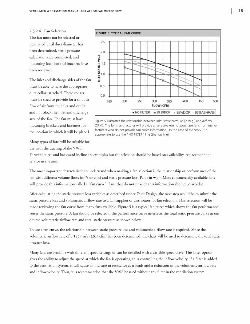
2.3.2.4. Fan Selection
The fan must not be selected or
purchased until duct diameter has
been determined, static pressure
calculations are completed, and
mounting location and brackets have
been reviewed.
The inlet and discharge sides of the fan
must be able to have the appropriate
duct collars attached. These collars
must be sized to provide for a smooth
flow of air from the inlet and outlet
and not block the inlet and discharge
area of the fan. The fan must have
mounting brackets and fasteners for
the location in which it will be placed.
Many types of fans will be suitable for
use with the ducting of the VWS.
Forward curve and backward incline are examples but the selection should be based on availability, replacement and
service in the area.
The most important characteristic to understand when making a fan selection is the relationship or performance of the
fan with different volume flows (m3/s or cfm) and static pressure loss (Pa or in w.g.). Most commercially available fans
will provide this information called a “fan curve”. Fans that do not provide this information should be avoided.
After calculating the static pressure loss variables as described under Duct Design, the next step would be to submit the
static pressure loss and volumetric airflow rate to a fan supplier or distributor for fan selection. This selection will be
made reviewing the fan curve from many fans available. Figure 5 is a typical fan curve which shows the fan performance
verses the static pressure. A fan should be selected if the performance curve intersects the total static pressure curve at our
desired volumetric airflow rate and total static pressure as shown below.
To use a fan curve, the relationship between static pressure loss and volumetric airflow rate is required. Since the
volumetric airflow rate of 0.1257 m3/s (267 cfm) has been determined, the chart will be used to determine the total static
pressure loss.
Many fans are available with different speed settings or can be installed with a variable speed drive. The latter option
gives the ability to adjust the speed at which the fan is operating, thus controlling the inflow velocity. If a filter is added
to the ventilation system, it will cause an increase in resistance as it loads and a reduction in the volumetric airflow rate
and inflow velocity. Thus, it is recommended that the VWS be used without any filter in the ventilation system.
VENTILATED WORKSTATION MANUAL FOR AFB SMEAR MICROSCOPY | 15
FIGURE 5. TYPICAL FAN CURVE.
Figure 5 illustrates the relationship between inlet static pressure (in w.g.) and airflow(CFM). The fan manufacturer will provide a fan curve (do not purchase fans from manu-facturers who do not provide fan curve information). In the case of the VWS, it isappropriate to use the “NO FILTER” line (the top line).
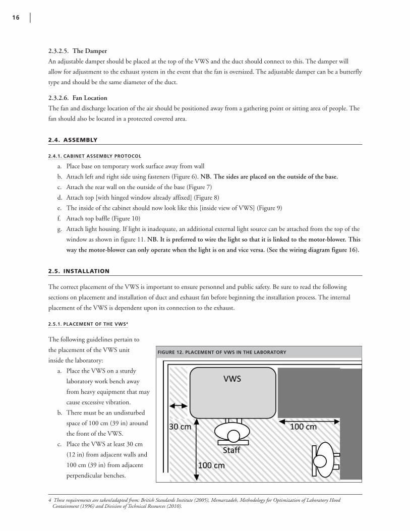
2.3.2.5. The Damper
An adjustable damper should be placed at the top of the VWS and the duct should connect to this. The damper will
allow for adjustment to the exhaust system in the event that the fan is oversized. The adjustable damper can be a butterfly
type and should be the same diameter of the duct.
2.3.2.6. Fan Location
The fan and discharge location of the air should be positioned away from a gathering point or sitting area of people. The
fan should also be located in a protected covered area.
2.4. ASSEMBLY
2.4.1. CABINET ASSEMBLY PROTOCOL
a. Place base on temporary work surface away from wall
b. Attach left and right side using fasteners (Figure 6). NB. The sides are placed on the outside of the base.
c. Attach the rear wall on the outside of the base (Figure 7)
d. Attach top [with hinged window already affixed] (Figure 8)
e. The inside of the cabinet should now look like this [inside view of VWS] (Figure 9)
f. Attach top baffle (Figure 10)
g. Attach light housing. If light is inadequate, an additional external light source can be attached from the top of the
window as shown in figure 11. NB. It is preferred to wire the light so that it is linked to the motor-blower. This
way the motor-blower can only operate when the light is on and vice versa. (See the wiring diagram figure 16).
2.5. INSTALLATION
The correct placement of the VWS is important to ensure personnel and public safety. Be sure to read the following
sections on placement and installation of duct and exhaust fan before beginning the installation process. The internal
placement of the VWS is dependent upon its connection to the exhaust.
2.5.1. PLACEMENT OF THE VWS4
The following guidelines pertain to
the placement of the VWS unit
inside the laboratory:
a. Place the VWS on a sturdy
laboratory work bench away
from heavy equipment that may
cause excessive vibration.
b. There must be an undisturbed
space of 100 cm (39 in) around
the front of the VWS.
c. Place the VWS at least 30 cm
(12 in) from adjacent walls and
100 cm (39 in) from adjacent
perpendicular benches.
4 These requirements are taken/adapted from: British Standards Institute (2005), Memarzadeh, Methodology for Optimization of Laboratory HoodContainment (1996) and Division of Technical Resources (2010).
16 |
FIGURE 12. PLACEMENT OF VWS IN THE LABORATORY

VENTILATED WORKSTATION MANUAL FOR AFB SMEAR MICROSCOPY | 17
FIGURE 10. ATTACHING THE BAFFLE
FIGURE 6. JOINING THE SIDES TO THE BASE
FIGURE 8. ATTACHING THE WINDOW FIGURE 9. EXHAUST DUCT COLLAR SPACE
FIGURE 7. JOINING THE BACK TO THE BASE AND SIDES
Exhaust duct collar(without baffle)
baffle
FIGURE 11. EXTERNAL LIGHT SOURCE
CABINET ASSEMBLY PROTOCOL
a. Place base on temporary work surface away from wallb. Attach left and right side using fasteners (Figure 6). NB. The sides are placed on the outside of the base.
c. Attach the rear wall on the outside of the base (Figure 7)
d. Attach top [with hinged window already affixed] (Figure 8) e. The inside of the cabinet should now look like this [inside viewof VWS] (Figure 9)
f. Attach top baffle (Figure 10) g. Attach light housing. If light is inadequate, an additionalexternal light source can be attached from the top of thewindow as shown in figure 11.

18 |
FIGURE 14. PLACING DAMPER AND ATTACHING DUCT
FIGURE 13. ANOTHER WAY OF PLACING THE VWS IN THE LABORATORY.
2.5.2. ASSEMBLY AND INSTALLATION OF DUCT
The VWS unit must be placed inside the laboratory according to the guidelines in section 2.5.1 and the requirements for
placement of the exhaust fan (section 2.5.3).
a. Place damper on top of exhaust collar
b. Fasten damper with screws
c. Tape/seal damper with metal duct tape
d. Adjust damper to be fully open NB. Ensure arrow is pointing in the correct direction (direction of airflow)
d. Ensure the VWS is at least
100 cm (39 in) from an
opposing wall.
e. The VWS should be at
least 150 cm (59 in) away from
opposing benches (and
doorways) or areas with
occasional traffic.
2.5.3. INSTALLATION OF THE EXHAUST FAN
The fan should be located at or near the outer wall and should be supported by a sturdy stand or bracket. The fan and air
duct should have weather cap and bird protector installed. The duct should discharge the air away from people and in
open space. The fan should also be located in a covered protected area.
2.6. ELECTRICAL SAFETY AND WIRING
The use of high quality electrical cable and components meeting the local code are imperative for the safety of the user
and longevity of the equipment. Figure 16 displays the wiring diagram for the VWS lights and blower.
Electrical wiring for the light source should be firmly attached to the VWS; and the appropriate casing should be used for
the fan. It is preferable to use the laboratory power switch to control the light and fan. Alternately, an electrical switch
box can be mounted at the top of the VWS.
A light source can be mounted externally on the top of window panel and tightly fixed with screws or clamps. If the light
source is desired to be mounted inside the VWS, it can be tightly screwed either inside the window or onto the baffle. A
small hole in the side panel can be made and a rubber bung should be used to pass the wire and to seal the hole. The hole
can also be sealed with, e.g. caulking or electrical tape.
VENTILATED WORKSTATION MANUAL FOR AFB SMEAR MICROSCOPY | 19
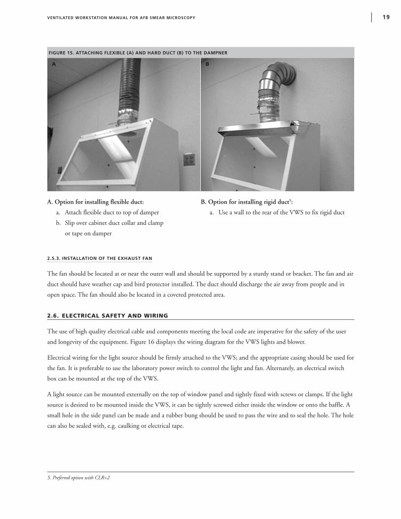
FIGURE 15. ATTACHING FLEXIBLE (A) AND HARD DUCT (B) TO THE DAMPNER
A B
A. Option for installing flexible duct:
a. Attach flexible duct to top of damper
b. Slip over cabinet duct collar and clamp
or tape on damper
B. Option for installing rigid duct5:
a. Use a wall to the rear of the VWS to fix rigid duct
5. Preferred option with CLR>2
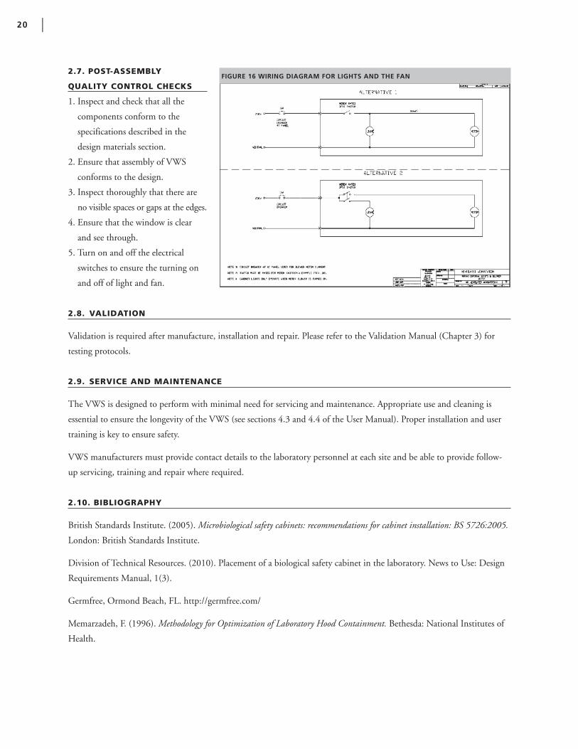
2.7. POST-ASSEMBLY
QUALITY CONTROL CHECKS
1. Inspect and check that all the
components conform to the
specifications described in the
design materials section.
2. Ensure that assembly of VWS
conforms to the design.
3. Inspect thoroughly that there are
no visible spaces or gaps at the edges.
4. Ensure that the window is clear
and see through.
5. Turn on and off the electrical
switches to ensure the turning on
and off of light and fan.
2.8. VALIDATION
Validation is required after manufacture, installation and repair. Please refer to the Validation Manual (Chapter 3) for
testing protocols.
2.9. SERVICE AND MAINTENANCE
The VWS is designed to perform with minimal need for servicing and maintenance. Appropriate use and cleaning is
essential to ensure the longevity of the VWS (see sections 4.3 and 4.4 of the User Manual). Proper installation and user
training is key to ensure safety.
VWS manufacturers must provide contact details to the laboratory personnel at each site and be able to provide follow-
up servicing, training and repair where required.
2.10. BIBLIOGRAPHY
British Standards Institute. (2005). Microbiological safety cabinets: recommendations for cabinet installation: BS 5726:2005.
London: British Standards Institute.
Division of Technical Resources. (2010). Placement of a biological safety cabinet in the laboratory. News to Use: Design
Requirements Manual, 1(3).
Germfree, Ormond Beach, FL. http://germfree.com/
Memarzadeh, F. (1996). Methodology for Optimization of Laboratory Hood Containment. Bethesda: National Institutes of
Health.
20 |
FIGURE 16 WIRING DIAGRAM FOR LIGHTS AND THE FAN

3. Validation Manual
3.1 PURPOSE
The purpose of this document is to guide manufacturers, installation engineers and members of regulatory bodies on the
requirements and procedures for validating the ventilated workstation (VWS).
Important: This document is specifically designed for validation of the VWS. It does not provide guidance for validating
any other safety devices including BSCs, laminar flow, clean benches and fume hoods.
3.2. BACKGROUND
The VWS, when designed and built to the exact specifications detailed in the “Manufacturers’ Manual”, should conform
to the quality standards of the prototype. The design, fabrication, and installation of the prototype VWS has been
validated according to the protocols detailed within this manual.
It is necessary for the manufacturer to validate every manufactured VWS due to variations in component parts and
specific site installation requirements.
3.3. INTRODUCTION TO VALIDATION REQUIREMENTS
Each VWS design is validated for all tests described within the Validation Manual. After installation and repair, the
required validation tests include:
• Inflow velocity
• Airflow smoke test
It is essential to record the date, evaluator initials and validation test results immediately in the validation checklist /
logbook provided (see appendix V1). All results must be recorded, even those falling outside of the passing range. All
failing test results, observations and corrective actions must be recorded.
Each protocol describes a test based on an international consensus standard. The majority of tests require special
measuring devices. In some cases, alternative testing protocols have been suggested in case measuring equipment is
unavailable at the manufacturing site or testing laboratory. The alternative protocols do not employ standardized
equipment; therefore, it is important to note that many are not based on consensus standards. Despite this, these tests
will ensure proper functioning of the VWS. The exceptions are the tests critical to ensuring adequate inflow velocity and
protection to the user. For these, the testing laboratory or manufacturer must be in possession of an airflow meter and a
safe source of generating smoke. Cigarette and other tobacco products are prohibited in the laboratory.
The validation equipment must be well-maintained and periodically calibrated. The validation equipment should always
be used according to the manufacturer’s instructions.
VENTILATED WORKSTATION MANUAL FOR AFB SMEAR MICROSCOPY | 21
3.4. VALIDATION PROTOCOLS
3.4.1. LIGHT INTENSITY TEST USING A LIGHT METER6
3.4.1.1. Purpose
The VWS is designed to permit light to illuminate the work area at sufficient levels for procedures to be conducted
within. This test determines the light intensity on the work surface of the VWS in lux (lx).
3.4.1.2. Apparatus
A photoelectric illumination (light) meter accurate to ± 10%. The illumination meter shall be calibrated in accordance
with the manufacturer's instructions.
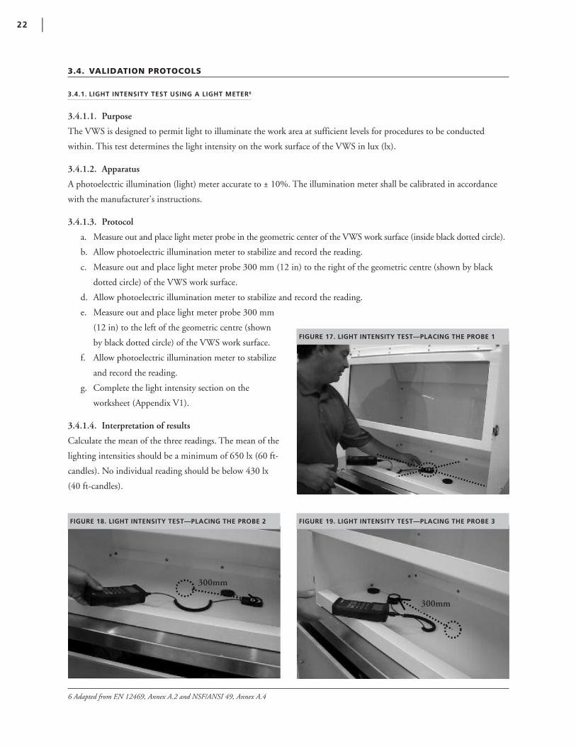
3.4.1.3. Protocol
a. Measure out and place light meter probe in the geometric center of the VWS work surface (inside black dotted circle).
b. Allow photoelectric illumination meter to stabilize and record the reading.
c. Measure out and place light meter probe 300 mm (12 in) to the right of the geometric centre (shown by black
dotted circle) of the VWS work surface.
d. Allow photoelectric illumination meter to stabilize and record the reading.
e. Measure out and place light meter probe 300 mm
(12 in) to the left of the geometric centre (shown
by black dotted circle) of the VWS work surface.
f. Allow photoelectric illumination meter to stabilize
and record the reading.
g. Complete the light intensity section on the
worksheet (Appendix V1).
3.4.1.4. Interpretation of results
Calculate the mean of the three readings. The mean of the
lighting intensities should be a minimum of 650 lx (60 ft-
candles). No individual reading should be below 430 lx
(40 ft-candles).
22 |
FIGURE 18. LIGHT INTENSITY TEST—PLACING THE PROBE 2 FIGURE 19. LIGHT INTENSITY TEST—PLACING THE PROBE 3
FIGURE 17. LIGHT INTENSITY TEST—PLACING THE PROBE 1
300mm
300mm
6 Adapted from EN 12469, Annex A.2 and NSF/ANSI 49, Annex A.4

3.4.2. LIGHT INTENSITY TEST BY EYE
3.4.2.1. Protocol for light intensity test without light meter.
a. Place a piece of hand written or printed white paper (92 brightness) with black fonts (Times New Roman) of font
size 12 (without bold or italics) on the surface of the cabinet.
b. Complete the light intensity test by eye section on the worksheet (Appendix V1).
3.4.2.2. Interpretation of results
There should be ample light in the cabinet to read the writing easily.
3.4.3. NOISE LEVEL TEST USING SOUND METER7
When connected to a suitable exhaust system, the VWS
should not produce any excessive noise such as to interfere
with work.
3.4.3.1. Purpose
This test provides a uniform method for measuring the
noise level produced by the VWS when functioning at
normal operating airflow.
3.4.3.2. Apparatus
The sound meter should meet the following requirements:
minimum accuracy of ± 1 Decibel (dBA), resolution of
1 dBA, range of 50 to 100 dBA and using the “A” weighting scale set up according to the manufacturer’s instructions.
3.4.3.3. Protocol
a. Turn on the VWS and lights.
b. Set up sound meter 1 m (39 in) from the front center and 1 m (39 in) above the VWS work surface (as indicated
by the black dotted lines in Figure 20)8.
c. Wait for sound meter to stabilize. Measure and record noise level in dBA.
d. Turn off VWS and lights and measure background noise level.
e. Record background and VWS noise level results on the worksheet.
f. Complete the noise level section of the worksheet (Appendix V1).
3.4.3.4. Interpretation of results.
The noise level in front of the VWS should not exceed 67 dBA when the ambient sound level is 57 dB or less. If the
background noise level is more than 57 dBA, the reading should be corrected according to tables provided in the sound
meter operator’s manual.
VENTILATED WORKSTATION MANUAL FOR AFB SMEAR MICROSCOPY | 23
FIGURE 20. NOISE LEVEL TEST
7. Taken/adapted from NSF/ANSI 49 – 2008.
8. Taken/adapted from EN12469.

FIGURE 22. VIBRATION TEST – PLACING THE BEAKERFIGURE 21. VIBRATION TEST – PLACING THE PROBE 1
3.4.4. NOISE LEVEL TEST BY EAR
3.4.4.1. Protocol for noise level test without sound meter.
a. Turn on blower and lights.
b. Sit at VWS with second person situated 1 m (39 in) away to the side.
c. Testers should be able to hear one another when speaking in their normal voice.
g. Turn off blower and lights and notice ambient/background noise level as above.
d. Complete the noise level by ear section of the worksheet.
3.4.4.2. Interpretation of results
A normal talking voice should be audible 1 m (39 in) from the tester while he/she is seated facing the front of the VWS.
The background noise level must be addressed if a normal talking voice cannot be heard when the VWS is switched off.
3.4.5. VIBRATION TEST USING VIBRATION ANALYZER9
When connected to a suitable exhaust system, the VWS should not vibrate excessively such as to interfere with procedures.
3.4.5.1. Purpose
This test determines the amount of vibration in the VWS cabinet when operating under normal airflow conditions.
3.4.5.2. Apparatus
A vibration analyzer with a minimum reliability of 1.0 x 10⁻⁴ in (2.5 x 10⁻⁶ m) rms (root mean square) amplitude of
displacement or the ability to detect differences of this magnitude, set up in accordance with manufacturer's instructions.
3.4.5.3. Protocol
a. Turn on blower and lights.
b. Place the vibration analyzer probe at the geometric centre of the VWS work surface (indicated by black dotted circle
in Figure 21).
c. Wait for vibration analyzer to stabilize. Measure and record net displacement (in or m rms amplitude)
on the worksheet.
3.4.5.4. Interpretation of results.
The net displacement shall not exceed 2 x 10⁻³ in (5 x 10⁻⁵ m) rms amplitude at frequencies between 10 Hz and 10 kHz
in the center of the work surface when the cabinet is operating at the design volumetric airflow rate.
24 |
9. Taken/adapted from NSF/ANSI 49, Annex A.5

VENTILATED WORKSTATION MANUAL FOR AFB SMEAR MICROSCOPY | 25
FIGURE 24. STABILITY TEST – ENSURING RETURN TO 90 DEGREESFIGURE 23. STABILITY TEST – APPLYING PRESSURE
3.4.6. VIBRATION TEST BY EYE
3.4.6.1. Protocol for vibration test without vibration analyzer.
a. Turn on blower and lights.
b. Place a 200 ml beaker of water (about ½ full or containing 100 ml) in the geometric center of the work surface
(indicated by the black dotted circle in Figure 22).
c. Look for rippling on the water surface.
d. Record observations on the worksheet (Appendix V1).
3.4.6.2. Interpretation of results
The surface of the water should be still. Ripples are an indication of too much vibration in the cabinet.
3.4.7. STABILITY10
The cabinet shall be designed and constructed to resist deflection under applied forces and resist deflection of the work
surfaces under load.
3.4.7.1. Purpose
This test is recommended to be performed at the local manufacturing facility to ensure that the materials used to
construct the VWS are sturdy.
3.4.7.2. Apparatus
Carpenter’s square for measuring right angles.
3.4.7.3. Protocol
a. With the blower and lights turned off, place the square against the right hand side of the VWS.
b. Holding the square steady with the left hand, apply pressure to the top of the VWS with the right hand until the
unit has displaced 20-30 mm (0.8-1.2 in). NB. There will be some movement in the VWS however, the unit
should not displace easily (Figure 23).
c. Hold the unit in the displaced position for a few seconds and then let go. Remember to keep hold of the square in
its original position (Figure 24).
d. Repeat steps ‘c’ and ‘d’ on the left hand side of the VWS.
e. Record observations on the worksheet (Appendix V1).
3.4.7.4. Interpretation of results.
The left and right hand sides of the VWS should return to a 90 degree angle (against the square) after pressure is released.
10. Taken/adapted from NSF/ANSI 49, Section 6.8
30 mm

3.4.8. INFLOW VELOCITY11 (RESTRICTED ACCESS /100 MM [4 IN] METHOD)
Determination of the air inflow velocity through the work access opening is one of the most important validation tests.
This test verifies the correct amount of air is being pulled through the VWS by the extractor fan. Incorrect inflow
velocity may lower the level of protection to the worker.
3.4.8.1. Purpose
The purpose of this test is to demonstrate that the VWS is capable of achieving the required inward airflow (as validated
to provide containment).
3.4.8.2. Apparatus
A hotwire anemometer with a suitable range and sensitivity should be used, and should be calibrated according to
manufacturer’s recommendations. In addition, a flat sheet of cardboard (or hardboard) and tape are required.
3.4.8.3. Protocol
a. Cut and tape in place a rectangular piece of cardboard 150 mm x 900 mm (6 in x 36 in) long to fit into the top of
the 250 mm x 900 mm (10 in x 36 in) access opening. This will leave an opening along the bottom edge of
approximately 100 mm x 900 mm (4 in x 36 in) for an open area of 0.09 m2 (1 ft2) (Figure 25).
b. Measure and mark along the 100 mm (4 in) opening, 9 readings, starting 50 mm (2 in) from the left sidewall with
100 mm (4 in) spacing. The 9 readings, starting from the left side of edge of the 100 mm (4 in) opening measure:
50 mm (2 in), 150 mm (6 in), 250 mm (10 in), 350 mm (14 in), 450 mm (18 in), 550 mm (22 in), 650 mm
(26 in), 750 mm (30 in), and 850 mm (34 in) (Figure 26).
c. Turn on the blower and lights.
d. Place the hotwire anemometer probe tip filament center along the line of the 100 mm (4 in) opening, with the
probe tip oriented upward.
26 |
FIGURE 26. VWS WITH CARDBOARD MARKINGSFIGURE 25. INWARD AIRFLOW TEST USING CARDBOARD INSERT
Open area of approx. 0.9 m2
Marked Readings
11. Adapted from EN 12469

e. The probe should be held against the bottom edge of the work station opening, oriented in a vertical, upward
position, with each of the 9 readings taken 50 mm (2 in) up from the bottom edge of the work station or half way
up in the vertical plane of the 100 mm (4 in) opening. Measurements are taken with reference to the center of the
filament probe located near the end of the probe tip.
f. For each reading, hold the probe for a minimum of 10 seconds and record the average velocity reading measured
for that location (in meters per second).
g. Record observations on the worksheet (Appendix V1).
3.4.8.4. Calculations
Fixed parameters for the designed VWS and opening:
AreaRestricted Access = Length x Height
AreaRestricted Access = 0.10 m x 0.90 m = 0.09 m2
AreaDesign Access = Length x Height
AreaDesign Access = 0.25 m x 0.90 m = 0.225 m2
Measured average airflow form anemometer: Velocity (m/s)
Volumetric Airflow Rate (QRestricted Access) = Velocity x Area = Velocity x 0.09 m2
VelocityCalculated for design Access = QRestricted Access /AreaDesign Access
Example:
Suppose average measured inflow velocity through the restricted access = 0.95 m/s
QRestricted Access = 0.95 m/s x 0.09 m2 = 0.0855 m3/s Or = 181.2 cfm
VelocityCalculated for design Access = QRestricted Access /AreaDesign AccessVelocityCalculated for design Access = 0.0855 m
3/s / 0.225 m2 = 0.38 m/s Or = 74.8 fpm
Conclusion: Both total volumetric airflow rate and the calculated inflow velocity are within the design standards;
however, they are near the lower limit.
3.4.8.5. Interpretation of results.
The average inflow air velocity for the VWS should not be less than 0.35 m/s (69 fpm). No individual measurement
should differ from the mean by more than +/- 0.1 m/s (20 fpm). The fan should be adjusted and test repeated until the
average calculated inflow velocity is between 0.35 – 0.55 m/s (69-108 fpm).
3.4.8.6. Volumetric Airflow rate Adjustments
Adjust the inflow velocity by increasing or decreasing the exhaust volumetric airflow rate. If the average inflow velocity is
too low, increase the exhaust flow. If the average inflow velocity is too high, decrease the exhaust volumetric airflow rate.
Adjustments may be made by changing the fan speed, by adjusting the damper, or both. Repeat until the proper inflow
velocity from the measurements and calculations has been obtained.
VENTILATED WORKSTATION MANUAL FOR AFB SMEAR MICROSCOPY | 27

3.4.9. DIRECT INFLOW MEASUREMENT (DIM)12
3.4.9.1. Purpose
This test determines the measured and calculated inflow velocity through the work access opening and the calculated exhaust
flow volume rate. A minimum of five individual volumetric readings shall be taken and averaged using a direct reading
instrument. It may be used in place of the restricted access method shown in section 3.4.8. Either method may be used.
3.4.9.2. Apparatus
The direct inflow measurement (DIM) instrument shall be used to obtain direct measurement of inflow volume. An
instrument with an accuracy of +/- 3% of reading +/- 0.003 m³/s (+/- 7 ft³ /min) shall be used for this test. An example
of an acceptable instrument is a calibrated, NIST traceable flow hood.
3.4.9.3. Protocol
a. Tape the DIM instrument flow hood to the center of the front opening of the ventilated workstation. Seal the
open areas on either side of the capture hood portion of the DIM as necessary. Tape and simple closure panels
(paper, cardboard, or wood) could be used for sealing (Figure 27).
b. The VWS exhaust blowers must remain in operation during testing. Take at least five readings, and average them
to determine inflow volume rate. Care should be taken not to restrict the airflow through the instrument intake
area (i.e. do not stand directly in front of the DIM flow hood while performing the measurements (Figure 28)).
c. Calculate the average inflow velocity in meters per second (or feet per minute) by dividing the average inflow
volume rate in cubic meters per second (cubic feet per minute) by the work access opening area in square meters
(square feet) (Figure 29).
d. Include the following in the reported data: individual inflow volume rate readings, average inflow volume rate,
work access opening dimensions and area, average inflow velocity.
28 |
FIGURE 27. ATTACHMENT OF THE DIM FLOW HOOD TO THE VWS
DIM hood (cone) sealed to the front of a VWS
Panels used to seal the rest of the work access opening
Direct Inflow Measurement (DIM) instrument attached to a hood (cone) on the front of a VWS
Airflow into the DIM
12. NSF/ANSI 49, Annex A.9

3.4.10. AIRFLOW SMOKE TEST13
3.4.10.1.Purpose
This test determines that the airflow along the entire perimeter of the VWS work access opening is inward and that there
is no escape of air to the outside.
3.4.10.2.Apparatus
A source of smoke should be used to provide visualization of airflow patterns in the VWS. Incense sticks or other small
handheld smoke producing items are appropriate. Bear in mind that smoking is never allowed in the clinical laboratory.
Cigarette and other tobacco related products are prohibited in the laboratory and must not be used.
3.4.10.3.Protocol
a. Turn on blower and lights.
b. Run the smoke source slowly along the entire external perimeter, approximately 40 mm (1.5 in) from the VWS
work access opening (Figure 30).
c. Record any observations on the worksheet (Appendix V1). Particular attention should be paid to corners and
vertical edges. No smoke should be refluxed (returned) out of the VWS once drawn in.
VENTILATED WORKSTATION MANUAL FOR AFB SMEAR MICROSCOPY | 29
FIGURE 30. AIRFLOW SMOKE TEST – EXTERNAL PERIMETER
FIGURE 28. THE DIM FLOW HOOD ATTACHED TO THE VWS FIGURE 29. THE DIM FLOW HOOD ATTACHED TO THE VWS
13. NSF/ANSI 49, Annex A.10 and ASHRAE 110, section 6.1
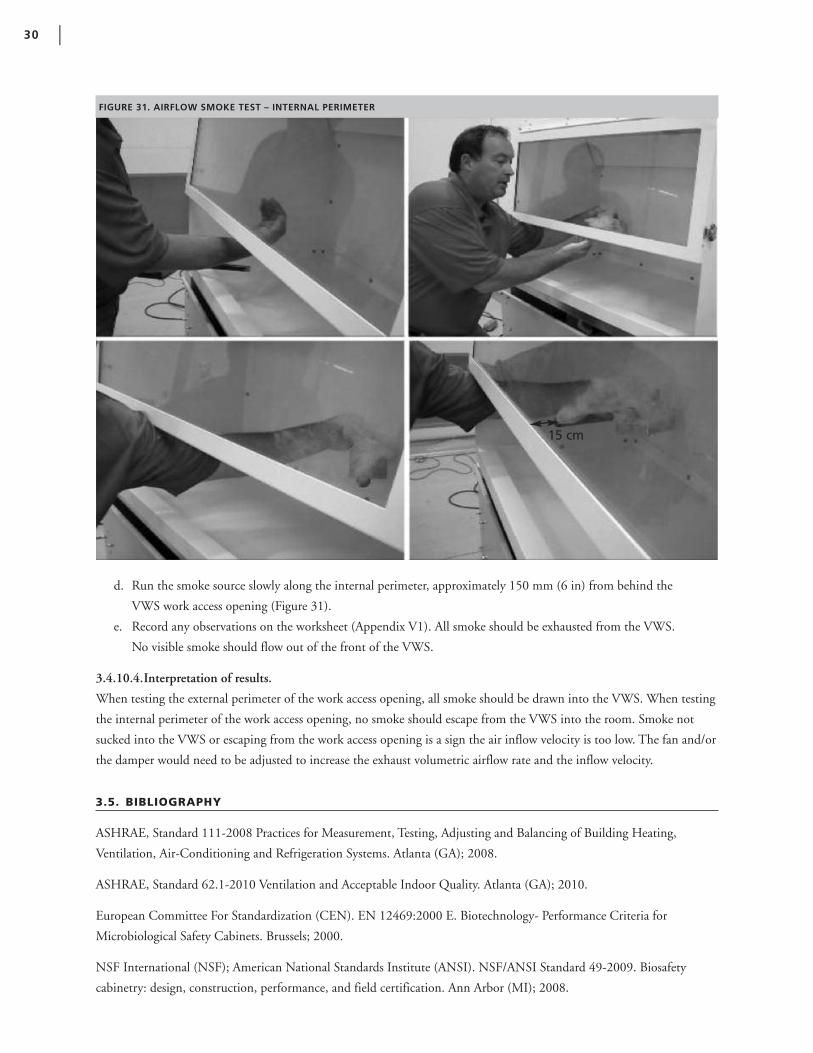
d. Run the smoke source slowly along the internal perimeter, approximately 150 mm (6 in) from behind the
VWS work access opening (Figure 31).
e. Record any observations on the worksheet (Appendix V1). All smoke should be exhausted from the VWS.
No visible smoke should flow out of the front of the VWS.
3.4.10.4.Interpretation of results.
When testing the external perimeter of the work access opening, all smoke should be drawn into the VWS. When testing
the internal perimeter of the work access opening, no smoke should escape from the VWS into the room. Smoke not
sucked into the VWS or escaping from the work access opening is a sign the air inflow velocity is too low. The fan and/or
the damper would need to be adjusted to increase the exhaust volumetric airflow rate and the inflow velocity.
3.5. BIBLIOGRAPHY
ASHRAE, Standard 111-2008 Practices for Measurement, Testing, Adjusting and Balancing of Building Heating,
Ventilation, Air-Conditioning and Refrigeration Systems. Atlanta (GA); 2008.
ASHRAE, Standard 62.1-2010 Ventilation and Acceptable Indoor Quality. Atlanta (GA); 2010.
European Committee For Standardization (CEN). EN 12469:2000 E. Biotechnology- Performance Criteria for
Microbiological Safety Cabinets. Brussels; 2000.
NSF International (NSF); American National Standards Institute (ANSI). NSF/ANSI Standard 49-2009. Biosafety
cabinetry: design, construction, performance, and field certification. Ann Arbor (MI); 2008.
30 |
FIGURE 31. AIRFLOW SMOKE TEST – INTERNAL PERIMETER
15 cm

3.6. APPENDICES
V1. VALIDATION CHECKLIST / LOGBOOK
V2. REFERENCE VALUES
VENTILATED WORKSTATION MANUAL FOR AFB SMEAR MICROSCOPY | 31
4. User Manual
4.1. OPERATION
The purpose of the VWS is to provide a safe work environment for preparing sputum smears for AFB staining or sample
manipulations that inactivate sputum specimens for automated molecular testing systems e.g., GeneXpert MTB/RIF
Assay from Cepheid (Padmapriya et al, 2010).
The VWS should never be used for procedures that increase the risk of generating aerosols including: decontamination or
concentration of sputum samples involving centrifugation or vortexing, and handling of solid or liquid cultures. Use of
the VWS should not replace attention to careful technique to minimize risks and assure high quality smears. Similar to
the WHO's recent Infection Control Guidelines and biosafety principles, use of the VWS is one engineering solution
that should be used in addition to administrative precautions such as having patients collect specimens outside of the
laboratory (World Health Organization, 2009).
The following steps should be performed before each use of the cabinet. Following these steps will ensure proper VWS
operation and equipment longevity:
4.1.1. STARTING UP
a) Switch on the VWS fan and light.
b) Check the VWS opening to ensure there are no obstructions.
c) Allow VWS to run for 5 min before beginning work.
d) Wipe down the cabinet internal surfaces with a disinfectant (see section 4.3).
e) Ensure the inward airflow by visual means (see section 4.2).
4.1.2. WORKING AT THE VWS
The following recommendations play a part in worker’s safety, comfort and health.
a) Assemble all items required for smear preparation inside the VWS before starting the work.
b) Use an adjustable chair or stool with a backrest and ensure sufficient legroom under the VWS.
c) Sit in a comfortable position with a straight back where the entire work surface can be viewed clearly.
d) Make sure there is enough light to see the work surface without the need to squint. It should be possible to read
handwritten sample identifiers easily.
e) Lay out samples and supplies neatly so that all items can be handled easily and the need to reach across the cabinet
is limited. Do not overcrowd or clutter the work surface. NB. It is important to minimize arm movement in the
VWS as this disrupts the flow of air.
f ) Place items in the VWS so that work flows from ‘clean’ to ‘contaminated’ areas. NB. A small waste bag/container
should be placed inside the VWS for collecting contaminated applicator sticks.
g) Open one specimen at a time and follow the standard operating procedure for smear preparation.
h) Prepared smears can be left inside the VWS for drying.
i) Once the slides are completely dry, bring them outside of the VWS for fixation.
j) Remove all samples, waste containers and remaining supplies from the VWS.
32 |

4.1.3. SHUTTING DOWN
a) Allow the VWS to run for 5 min after work has been completed.
b) Remove all materials, specimens and supplies from the VWS. Do not use the VWS to store items.
c) Wipe down the cabinet internal surfaces with a disinfectant (see section 4.3).
d) Turn off the VWS fan and light.
4.2. DAILY AIRFLOW CHECKS
An inward airflow check must be performed to ensure the VWS is functioning properly and providing protection to the
worker. This could be achieved by taping a thin plastic or paper strip at the top edge of the opening window. The strip
would flutter inside the VWS when turned-on. In case of any doubts, airflow checks using an anemometer (see section
4.2.2) must be performed to ensure the directional and sufficient airflow.
4.2.1. AIRFLOW MEASUREMENT EQUIPMENT (ANEMOMETER)14
An anemometer (either thermal or rotational/vane) is the preferred means to measure the flow of air drawn into the
VWS. Inflow checks using swinging vane anemometer could be performed daily.
4.2.1.1. Measuring the Intake Velocity in the VWS
The anemometer probe or vane should be placed 5 cm above the lower edge of the front window.
a) Airflow measurements should be taken at 8 points across the work surface (the intersection of the grid at points
1-8 in Figure 32).
b) Each measurement should be made for 60 seconds to allow anemometer to stabilize (take an average reading over
the 60 s).
c) Record the results of each measurement on the ‘Daily Checklist’ in Appendix A.
d) Take the average of the 8 measurements. The average should be between 0.35 – 0.55 m/s (69-108 fpm).
Warning: Do not use the VWS if the average intake velocity is less than 0.35 m/s or greater than 0.55 m/s. Record the
issue on the intake velocity worksheet and contact the laboratory manager, qualified engineer or manufacturer. Retain
a record of all contacts made and subsequent steps taken on the worksheet.
VENTILATED WORKSTATION MANUAL FOR AFB SMEAR MICROSCOPY | 33
90.6 cm
60 cm
FIGURE 32. POSITIONING THE ANEMOMETER TO MEASURE AIRFLOW (THE TUBERCULOSIS COALITION FOR TECHNICAL ASSISTANCE, 2010)
VWS Worksurface
14. Adapted from “Use and maintenance of class I and class II biological safety cabinets,” the Tuberculosis Coalition for Technical Assistance (TBCAP).

4.3. CLEANING
• Ensure that disinfectants and cleaning agents are suitable for use on the VWS surfaces and window and biocidal
for M. tuberculosis. Some of the commonly used disinfectants in laboratory are: 70% alcohol, 5% phenol, and
10% bleach (0.5% sodium hypochlorite).
• The internal surfaces of the VWS should be cleaned at least twice per day. This must be done before beginning
work at the start of the day and after finishing work at the end of the day.
• Waste must be removed from the VWS at the end of every day (and periodically throughout the day depending
upon workload).
• The VWS cabinet, including window and all other surfaces, should be cleaned and decontaminated with
disinfectant.
• Be sure to clean all surfaces, especially under the lip, the work access opening, corners, and baffle (sloped area
above internal surface of window).
NB. Bleach solutions may corrode metal surfaces of the VWS and should be followed immediately by wiping with
70% alcohol solution.
4.4. MONTHLY CHECKS
4.4.1. VISUAL INTEGRITY CHECK
The purpose of performing monthly visual integrity checks is to identify any potential structural or mechanical defects
that may require attention. These include problems with the exhaust fan or ducting that may lead to excessive noise and
vibration. All observations and any steps taken must be recorded on the checklist in Appendix U2.
a) Check the workstation internal and external surfaces for cracks, abrasions and corrosion.
b) Check the duct (externally) making sure there are no cracks and that the duct appears enclosed around the duct
outlet.
c) Check the window for cracks and scratches ensuring visibility of the internal work surface is adequate.
d) Check to ensure the light is fully functional.
e) Check that the cabinet does not vibrate excessively.
f ) Check the exhaust fan does not make excessive noise.
g) Record the results of the visual integrity check on the checklist in Appendix U2.
4.4.2. AIRFLOW CHECK
Monthly airflow checks by using anemometer (see section 4.2) must be performed to ensure the proper inflow velocity.
Follow the procedure as described and record results on the worksheet in Appendix U2. If results do not fall within
reference values, revalidate according to section 3.4.8.
4.4.3. SMOKE TEST
The smoke test determines that the airflow along the entire perimeter of the VWS work access opening is inward and
that there is no escape/reflux of air to the outside.
34 |

4.4.3.1. Smoke Test Equipment
A source of smoke should be used to provide visualization of airflow patterns in the VWS. Incense sticks or other small
handheld smoke-producing items are appropriate.
4.4.3.2. Smoke Test Protocol
NB. The smoke test (photos shown in section 3.4.10) was performed on a newly manufactured VWS in a clean
factory setting. When performing the smoke test in the laboratory setting, always wear personal protective equipment
(gloves and lab coat).
a) Turn on blower and lights.
b) Run the smoke source slowly along the entire external perimeter, approximately 40 mm (1.4 in) from the
VWS work access opening.
c) Record any observations on the worksheet (Appendix U2). Particular attention should be paid to corners and
vertical edges. No smoke should be refluxed out of the VWS once drawn in.
d) Run the smoke source slowly along the internal perimeter, approximately 150 mm (6 in) from behind the
VWS work access opening.
e) Run the smoke source slowly along the internal perimeter, approximately 150 mm (6 in).
f ) Record any observations on the worksheet (Appendix U2). All smoke should be exhausted from the VWS.
No visible smoke should flow out of the front of the VWS.
4.5. SAFETY PROCEDURES15
Laboratory personnel must follow good laboratory practice all the time. No eating, drinking, and smoking is allowed in
the laboratory. Food must not be stored in the laboratory refrigerators. If available, disposable gloves, a laboratory coat
and sturdy closed-toe shoes should be worn while working with potentially infectious material. Disposable gloves are for
one-time use only and must be taken off at the end of the each work session. Gloved hands, which could spread
contamination, must not touch surfaces such as door handles, telephones, pens, and microscope handles.
4.5.1. WHEN TO STOP USING THE VWS
Do not use the VWS in the event of the following:
• If the VWS or laboratory loses power.
• If the daily or monthly checks indicate a problem with airflow.
• If there is a spill inside the workstation.
4.5.2. WHAT TO DO DURING SUDDEN LOSS OF POWER OR SPILL
In the event of sudden power loss or spill:
a) Close any open sample tube.
b) Place items towards the back of the workstation (or at the back and away from the spilled material).
c) If responding to a spill, follow the procedure for clean up (section 4.5.3).
d) Do not use the VWS until the problem has been resolved (power has returned or spill has been properly cleaned
up); however, keep the VWS fan on.
VENTILATED WORKSTATION MANUAL FOR AFB SMEAR MICROSCOPY | 35
15. Adapted from (U.S. Department of Health and Human Services, 2007)

36 |
4.5.3. CLEANING UP SPILLS INSIDE THE VWS
For biohazardous spills within the VWS, clean-up should begin immediately and be performed while the cabinet is
running. Disinfectant should be applied in a manner that minimizes generation of aerosols.
Always follow universal safety precautions when handling broken glass containers with or without specimen or other sharps.
4.5.3.1. Materials required
• Absorbent tissue
• Rubber gloves
• Forceps
• Waste bags and containers
• Disinfectant
4.5.3.2. Protocol
a) Place absorbent tissue over the spill area and apply disinfectant solution liberally.
b) Pick up contaminated material using forceps and thick rubber gloves and place in an autoclavable container.
c) Discard contaminated waste in the appropriate manner.
d) Any laboratory worker in the vicinity of the spill must dispose of their gloves and immediately wash hands and
forearms. In case of wounds, cuts or abrasions, medical care should be sought immediately.
4.6. SERVICING, MAINTENANCE AND REPAIR
The VWS is designed to be maintained by the user. The user should perform all daily and monthly cleaning and
maintenance checks and keep a record of all results and observation.
Prior to servicing, maintenance or repair, the VWS must be decontaminated by cleaning all surfaces with an appropriate
disinfectant (see section 4.5).
Qualified personnel should be contacted in the following circumstances:
• When the average airflow measurement falls below 0.35 m/s (69 fpm) or above 0.55 m/s (108).
• If there are gaps in the joints or severe corrosion of the cabinet.
• If the window is broken or the view of the work surface is compromised such that work cannot be
performed with ease.
• If the smoke test results show smoke escaping from the work access opening after being drawn into the cabinet or
smoke escapes from another part of the cabinet or duct.
• If the duct has separated from the duct outlet.
• If the duct has cracked or degraded.
• If there is excessive noise or vibration.
The VWS can only be repaired by qualified personnel. The user should not attempt repair. The VWS should be re-
validated (inflow velocity and airflow smoke test) after major repair of the cabinet, replacement of a panel or window,
duct and fan (including component parts). Validation must be performed by qualified personnel.
4.7. BIBLIOGRAPHY
Padmapriya, P. B., Sivasubramani, S. K., Blakemore, R., Boehme, C., Perkins, M. D., & Fennelly, K. a. (2010, Oct).
Containment of bioaerosol infection risk by the Xpert MTB/RIF assay and its applicability to point-of-care settings.
Journal of Clinical Microbiology, 48(10), pp. 3551-3557.
The Tuberculosis Coalition for Technical Assistance. (2010). TB Diagnosis Tools. Retrieved from TB|CTA:
http://www.tbcta.org/Library/
U.S. Department of Health and Human Services. (2007). Biosafety in microbiological and biomedical laboratories. 5th.
Washington, District of Columbia, USA: U. S. Government Printing Office.
World Health Organization. (2009). WHO policy on TB infection control in health-care facilities, congregate settings
and households. Retrieved from WHO policy on TB infection control.:
http://whqlibdoc.who.int/publications/2009/9789241598323_eng.pdf
VENTILATED WORKSTATION MANUAL FOR AFB SMEAR MICROSCOPY | 37

4.8. APPENDICES
38 |
U1. DAILY CHECKLIST
DATE: SITE:
ROOM: VWS:
DAY STAFF CLEANING (WRITE YES/NO) AIRFLOW VISUAL CHECK OBSERVATIONS / COMMENTS
INITIALS PRE-WORK POST-WORK (WRITE YES/NO)
1
2
3
4
5
6
7
8
9
10
11
12
13
14
15
16
17
18
19
20
21
22
23
24
25
26
27
28
29
30
31

VENTILATED WORKSTATION MANUAL FOR AFB SMEAR MICROSCOPY | 39
U2. MONTHLY CHECKLIST
DAY: MONTH: YEAR:
SITE: ROOM: VWS:
NAME: SIGNATURE:
INTEGRITY CHECKLIST (VISUAL)
CHECK RESULT (CIRCLE ALL THAT APPLY) COMMENT
Internal surface OK Cracks Abrasions Corrosion
External surface OK Cracks Abrasions Corrosion
Duct OK Cracks Degradation Other
Window OK Cracks Scratches Degradation
Light OK Flicker No light Other/Comment
Vibration No vibration Vibration
Noise No noise Noise
Smoke Test PASS FAIL
INFLOW VELOCITY AND DIRECTION (USING ANEMOMETER)
POSITION RECORDED INFLOW VELOCITY (M/S OR FPM) COMMENT
1
2
3
4
5
6
7
8
Total
Average (total/8)
5. Main Appendices
5.1 GLOSSARY
Baffle | A static device inside and near the roof of the VWS that regulates the flow air.
Biological Safety Cabinet | A self-contained enclosure that provide protection for personnel, environment and/ or
products against hazardous microorganisms. Also known as microbiological safety cabinet or biosafety cabinet.
Damper | A bladed device that can be opened or closed to regulate airflow through a duct system.
Duct | Tubing (may be rigid or flexible) that connects the VWS from the exhaust collar in the cabinet roof to the
extractor fan in the wall. Also known as ductwork.
Duct Static Pressure | The pressure acting on the walls of a duct. (technically, it’s the total pressure minus the velocity
pressure).
Exhaust Collar | The opening in the roof of the VWS to which the duct is attached.
Fan Curve | Diagram giving the pressure/volume characteristics of a fan, and often the power required by the fan.
Intake Velocity | The rate of air intake through the VWS access opening (measured in m/s or fpm).
Motor-blower | The exhaust fan motor.
Refluxed | Air escaping out of the VWS back into the room rather than being draw out through the exhaust.
Total Static Pressure | In ventilation applications, static pressure is usually the difference between the absolute pressure in
an exhaust system and atmospheric pressure, such that static pressure less than atmospheric pressure is termed "negative
static pressure" and static pressure above atmospheric pressure is termed “positive static pressure.”13
Total Static Pressure loss | Sum of static pressure losses (negative) before and after the ventilator.
Validation | A series of tests carried out on each manufactured VWS to ensure minimum requirements of personnel
protection are attained.
Velocity | A vector measurement that specifies the time rate of change of displacement and direction; i.e., the first
derivative of the displacement with respect to time16.
Water Gauge | Inches of Water Gauge (in. w.g.) – A unit of pressure equal to the weight of a column of liquid water one
inch high at 20° C (1 in. w.g.=0.036 psi).
40 |
16. Source: The Baker Company (http://www.bakerco.com/glossary.html)

5.2 VWS FREQUENTLY ASKED QUESTIONS
1. What is the ventilated workstation?
The VWS is a partially-enclosed workspace from which air is drawn inward, away from the user and exhausted
outside of the laboratory.
2. Is it a bio-safety cabinet?
The VWS is not a biological safety cabinet. It has not been constructed nor tested to the same standards.
3. What is the use of ventilated workstation?
The purpose of VWS is to provide a safe work environment when preparing sputum smears for AFB staining.
4. Does it replace Good Laboratory Practices?
No, the VWS does not replace good laboratory practice.
5. Does it provide worker safety?
Yes, along with good laboratory practices a well maintained VWS provides worker safety.
6. Does it provide product protection?
No, the VWS does not provide product protection.
7. What samples can be processed in it?
The purpose of the VWS is to provide a safe work environment when preparing sputum smears for AFB staining or
sample manipulations that inactivate sputum specimens for automated molecular testing systems. Complete sample
inactivation for a rapid PCR based method has been published (Padmapriya et al, 2010).
8. Can it be used for other sample manipulations?
The VWS should never be used for procedures that increase the risk of generating aerosols including: decontamina-
tion or concentration of sputum samples involving centrifugation or vortexing, and handling of solid or liquid
cultures. It should never be used for culture or manipulation of cultures that may be growing M. tuberculosis.
9. Can it be used for initial TB culture?
The VWS cannot be used for initial TB culture.
10. Can it be used for other bacterial cultures?
The VWS has not been designed for manipulating bacterial cultures.
11. Can it be used for making smears from TB cultures?
No, the VWS should never be used for making smears from TB cultures.
12. Can it be used for performing TB drug susceptibility testing?
The VWS should never be used for performing TB drug susceptibility testing on liquid or solid cultures.
13. Does it mean that making smears from sputum specimens on an open bench is dangerous?
Making smears on an open bench does not carry an increased risk for transmission of TB provided good laboratory
practice is observed and the space has adequate natural ventilation with directional airflow away from the worker.
However, if such practices cannot be observed, the risk of exposure may be increased.
VENTILATED WORKSTATION MANUAL FOR AFB SMEAR MICROSCOPY | 41
14. We are making sputum smears on open benches for many years. What is the need for ventilated workstation now?
The World Health Organization supports the preparation of sputum smears for AFB staining on the open bench and
emphasizes the importance of using good laboratory practices to ensure personnel safety. The World Health Organi-
zation also offers advice on laboratory work flow and ventilation. The VWS expands the range of primary safety
barriers available to health workers and offers a safe alternative to laboratories where adequate ventilation is not avail-
able or possible.
15. Can smears be made from the sputum specimens on the open benches if there is a power failure?
Yes, as long as good laboratory practices and directional airflow away from the worker are ensured.
16. Is it battery operated?
The current model is based upon regular power. However, the use of battery depends upon the fan. As long as the fan
can be validated in providing adequate airflow, it can be operated by battery.
17. How many persons can work in it?
Only one person can use it at a time.
18. Where can I get the VWS?
You should contact your local or regional manufacturer. If you do not currently have a local or regional manufacturer,
you can provide this manual to companies with the capacity to fabricate the VWS17.
19. What is the assurance that locally made ventilated workstation will provide safe work environment?
As long as the local manufacturer follows the design and validation instructions correctly, the VWS will provide a safe
work environment.
20. Does the VWS require regular monitoring?
Yes, there are very important daily and monthly checks that must be performed. The results of these checks must be
recorded along with any actions taken.
21. Does the VWS require periodic validation?
The VWS only requires validation after manufacture, installation and major repairs (see section 4.6.). Users must
check and maintain the VWS according to the instructions for daily checks (see section 4.2.) and monthly checks
(see section 4.4.).
22. Who can perform the validation?
Validation of the VWS is relatively simple. However, it should only be performed by personnel trained by the manu-
facturer or in line with the requirements of the national body concerned with laboratory equipment. Each country or
region will need to set the competency standard.
23. Who can repair the ventilation workstation?
Repair of the VWS should only be performed by personnel trained by the manufacturer or in line with the require-
ments of the national body concerned with laboratory equipment. Each country or region will need to set the
competency standard.
42 |
17. No commercial manufacturers were available at the time of this manual going to press. It is intended that the VWS Manual be shared with potentialnational and international manufacturers so that VWSs may be provided as demand grows.

24. How it can be cleaned?
The VWS can be cleaned by surface wipe by using appropriate disinfectant.
25. Does it require decontamination prior to repair?
Yes, a thorough cleaning of internal surfaces by surface wipe method with appropriate disinfectant is required prior to
repair.
26. Can open flame be used inside the ventilated workstation?
No, the VWS is used for preparing and drying sputum smears only. Open flames could interfere with airflow and
cannot be used inside the VWS.
27. Where can I get more information on ventilated workstation?
You can get more information by contacting CDC: wwwn.cdc.gov/dls/ila/default.aspx,
APHL: www.aphl.org/AboutAPHL/publications/Pages/default.aspx or GLI: www.stoptb.org/wg/gli/
28. Is there any cost to the guidance document?
No, the guidance document is free.
29. Can I make the ventilated workstation for profit?
There are no restrictions on making the VWS for profit.
30. How much does the VWS cost?
The VWS design specifications were developed so that each unit could be made at minimum cost. It is not possible
to give an accurate figure for cost as input materials, labor and shipping (not to mention inflation over time) vary
greatly from country to country.
VENTILATED WORKSTATION MANUAL FOR AFB SMEAR MICROSCOPY | 43

44 |
5.3 CAD DRAWINGS FOR CABINET CONSTRUCTION
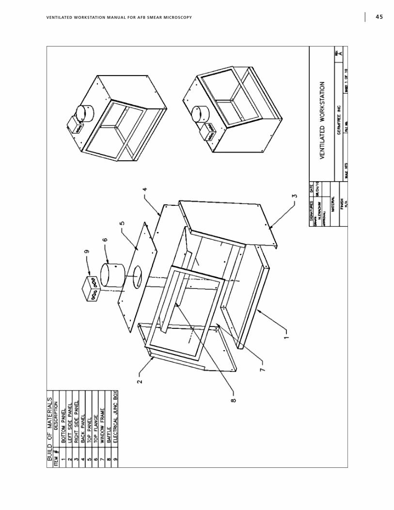
VENTILATED WORKSTATION MANUAL FOR AFB SMEAR MICROSCOPY | 45

46 |

VENTILATED WORKSTATION MANUAL FOR AFB SMEAR MICROSCOPY | 47

48 |

VENTILATED WORKSTATION MANUAL FOR AFB SMEAR MICROSCOPY | 49
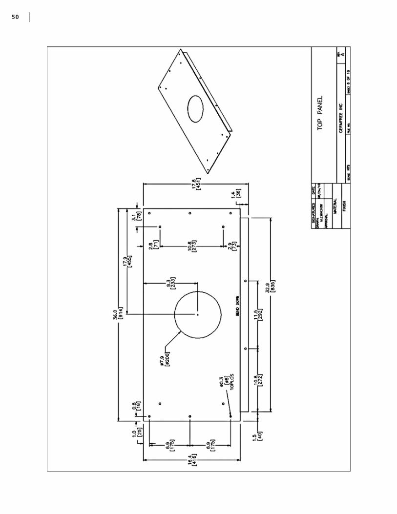
50 |

VENTILATED WORKSTATION MANUAL FOR AFB SMEAR MICROSCOPY | 51

52 |

VENTILATED WORKSTATION MANUAL FOR AFB SMEAR MICROSCOPY | 53
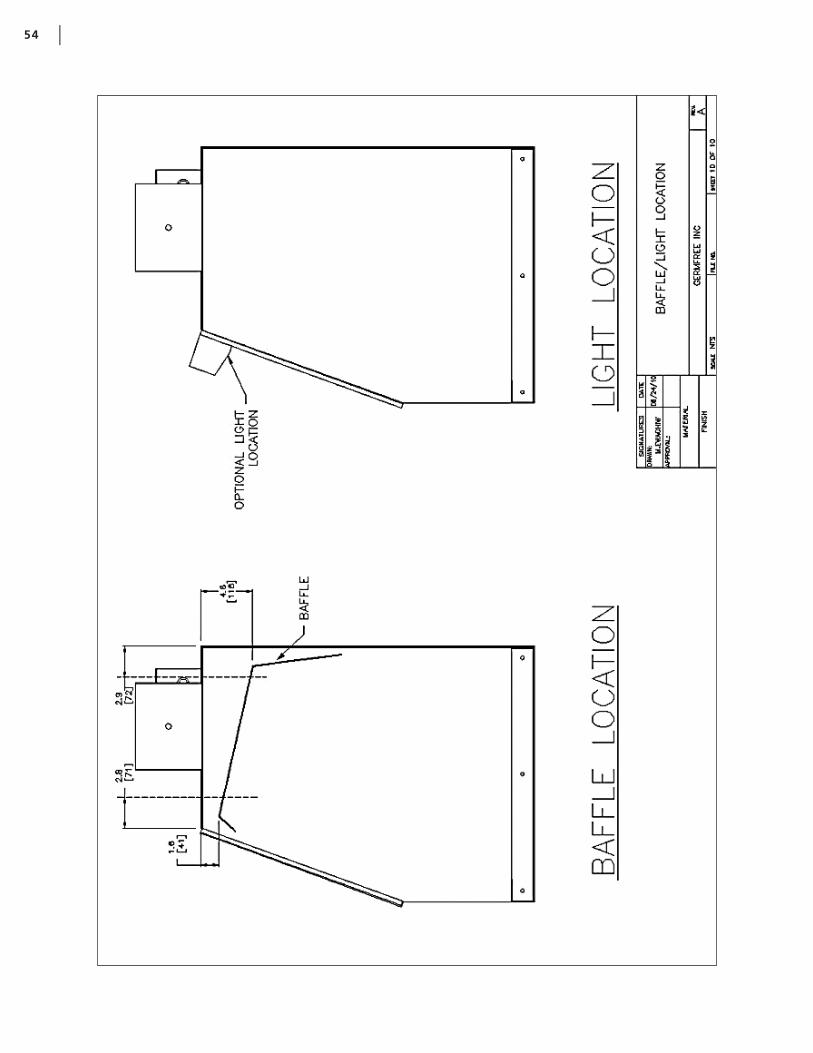
54 |

5.4 PROTOTYPE VWS TEST REPORT
This section provides the details of validation studies that were conducted on VWS to ensure that VWS will continuously
provide the safe work environment when preparing smears or performing other PCR based methods (e.g., GeneXpert
MTB/RIF Assay from Cepheid) on sputum specimens. This validation was conducted according to NSF 49 to define the
safe airflow limits for working in VWS by using Bacillus subtillis spores concentration modified to 5.0 x 10⁶ spores/ml.
VENTILATED WORKSTATION MANUAL FOR AFB SMEAR MICROSCOPY | 55

56 |
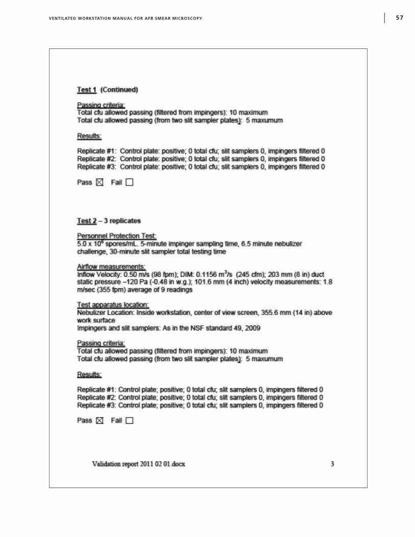
VENTILATED WORKSTATION MANUAL FOR AFB SMEAR MICROSCOPY | 57

58 |

VENTILATED WORKSTATION MANUAL FOR AFB SMEAR MICROSCOPY | 59
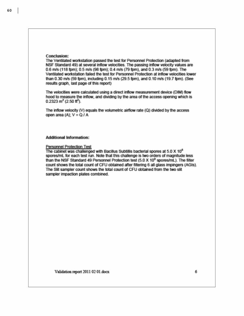
60 |

VENTILATED WORKSTATION MANUAL FOR AFB SMEAR MICROSCOPY | 61


This publication was supported by cooperative agreement number U62/CCU323096 from Centers for Disease Control and Prevention
(CDC). Its contents are solely the responsibility of the authors and do not necessarily represent the official views of the CDC.

![PerformanceofClinicalAlgorithmsfor Smear ... · 2 Tuberculosis Research and Treatment AFB smear-negative PTB for HIV-infected patients are still limited and inconsistent [6, 8]. This](https://img.pdfslide.us/doc/110x75/608cc3f7e89540310a24c5c9/performanceofclinicalalgorithmsfor-smear-2-tuberculosis-research-and-treatment.jpg)