Embed Size (px)
Citation preview
Ventilated Attics and Un-Vented Roof Assemblies Page 1 of 19 David B. Strunk, P.E., C.E.M.
Ventilated Attics and Un-Vented Roof Assemblies David B. Strunk, P.E., C.E.M. Strunk-Albert Engineering
Attic ventilation is common practice, and if installed properly, will function without a
problem. However, attics and roofs can be designed and constructed without ventilation.
In fact un-vented roof assemblies, such as conditioned attics and un-vented cathedral
ceilings, are generating more interest and are becoming a more common construction
technique. The decision to vent or not to vent is a design and construction choice not a
requirement by the building code. Model building codes allow both vented and un-
vented roof assemblies. The physics of heat and moisture transfer affect the design of
attic or roof ventilation but does not limit the choice.
The suggestion for attic ventilation first occurred in the mid 1930s and later became a
BOCA code requirement in 1948. Attic ventilation has become firmly established as an
important feature in sloped roof construction, most commonly found in residential and
light commercial construction. Lack of attic ventilation is often the cause of moisture,
mold, and rotten wood. Many asphalt shingle manufactures have requirements and
guidelines for attic ventilation in their installation instructions.
Providing proper attic ventilation can at times be difficult with complex roof designs.
The more complex the roof geometry, the easier it is to construction the roof assembly in
an un-vented manner. With complex roof designs, dormers, valleys, hips, skylights,
soffits, and multiple service penetrations it is often impractical to construction a vented
roof assembly with an airtight interior air barrier at the ceiling plane.
With floor space being tight and costly, it is common to locate mechanical equipment and
ductwork in the attic space. This, along with recessed lighting, results in numerous
penetrations that compromise the drywall air barrier and allows high exfiltration or
infiltration between the occupied space and the ventilated attic. All ductwork will leak;
some more than others. This means conditioned air is entering the ventilated attic. High
exfiltration and duct leakage allows heat and moisture to enter the attic. Moisture can
condense on the cold surfaces and the heat can cause ice dams when there is snow on the
roof.
Ventilated Attics and Un-Vented Roof Assemblies Page 2 of 19 David B. Strunk, P.E., C.E.M.
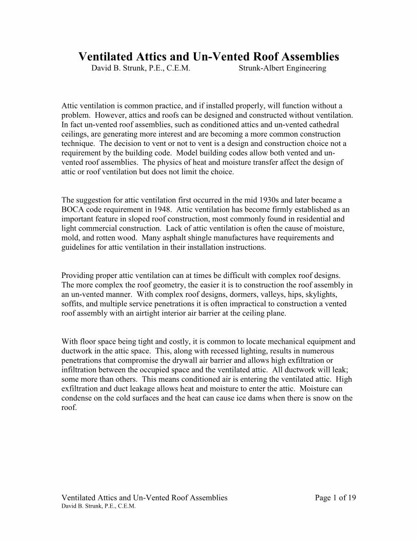
Photo – 1: Condensation can occur in an attic space when
there is not adequate ventilation or there is excessive humid
air transfer to the attic.
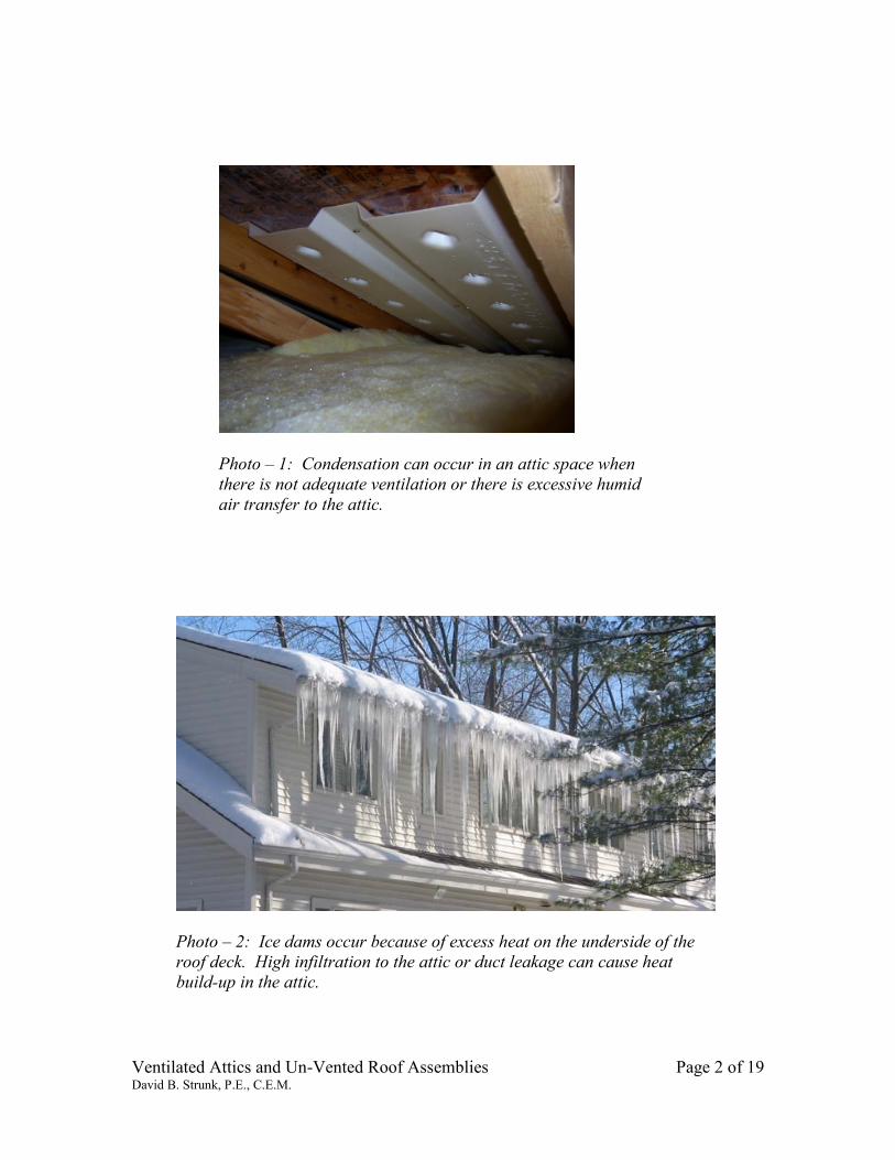
Photo – 2: Ice dams occur because of excess heat on the underside of the
roof deck. High infiltration to the attic or duct leakage can cause heat
build-up in the attic.
Ventilated Attics and Un-Vented Roof Assemblies Page 3 of 19 David B. Strunk, P.E., C.E.M.
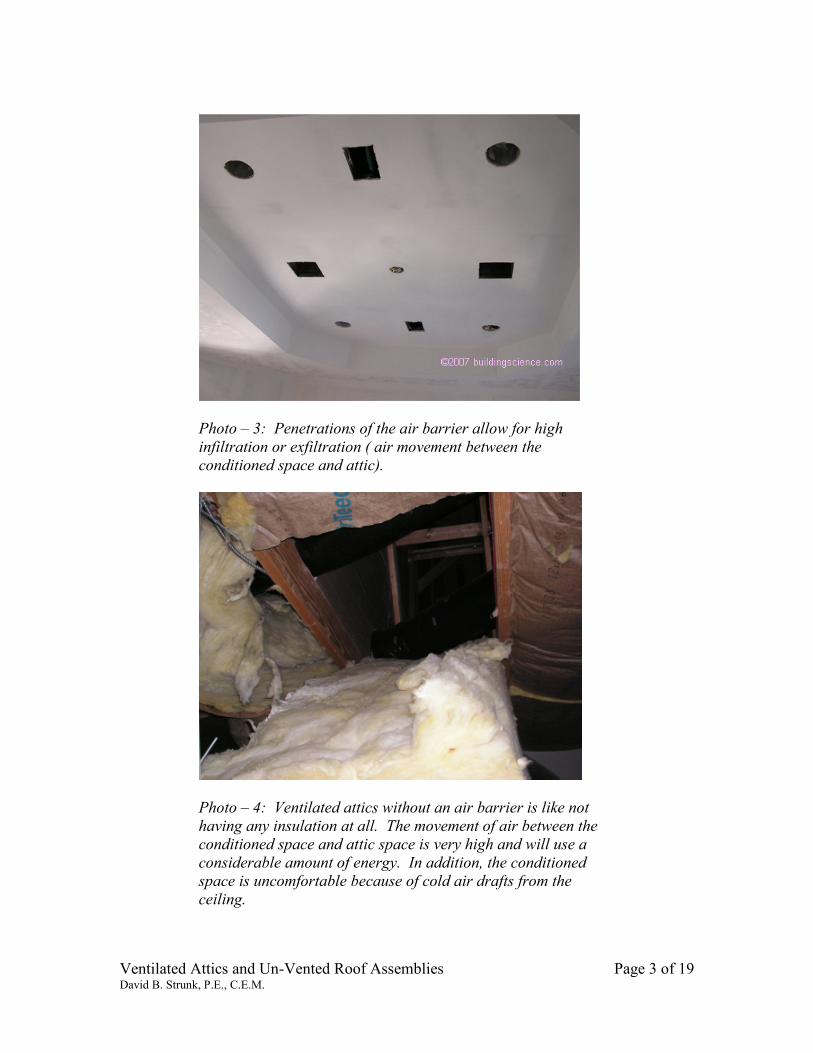
Photo – 3: Penetrations of the air barrier allow for high
infiltration or exfiltration ( air movement between the
conditioned space and attic).
Photo – 4: Ventilated attics without an air barrier is like not
having any insulation at all. The movement of air between the
conditioned space and attic space is very high and will use a
considerable amount of energy. In addition, the conditioned
space is uncomfortable because of cold air drafts from the
ceiling.
Ventilated Attics and Un-Vented Roof Assemblies Page 4 of 19 David B. Strunk, P.E., C.E.M.
There are significant energy advantages to moving the thermal boundary to the underside
of the roof deck and not ventilating the attic space. The mechanical equipment is now
located in conditioned space so any air leakage or heat loss is to the conditioned space not
the unconditioned attic. The first reaction of most people is that this will have a high heat
loss because of the additional volume to heat. But the reduction in infiltration through
the air barrier and the elimination of duct air leakage more than offsets the additional heat
loss from the larger conditioned volume of conditioned space. Many building owners are
happy to have the additional space provided by a conditioned attic.
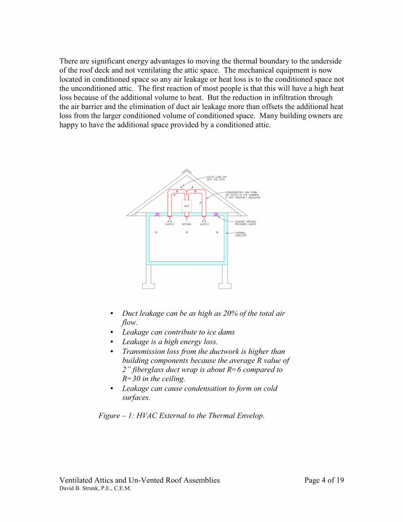
• Duct leakage can be as high as 20% of the total air flow.
• Leakage can contribute to ice dams • Leakage is a high energy loss. • Transmission loss from the ductwork is higher than
building components because the average R value of
2” fiberglass duct wrap is about R=6 compared to
R=30 in the ceiling.
• Leakage can cause condensation to form on cold surfaces.
Figure – 1: HVAC External to the Thermal Envelop.
Ventilated Attics and Un-Vented Roof Assemblies Page 5 of 19 David B. Strunk, P.E., C.E.M.
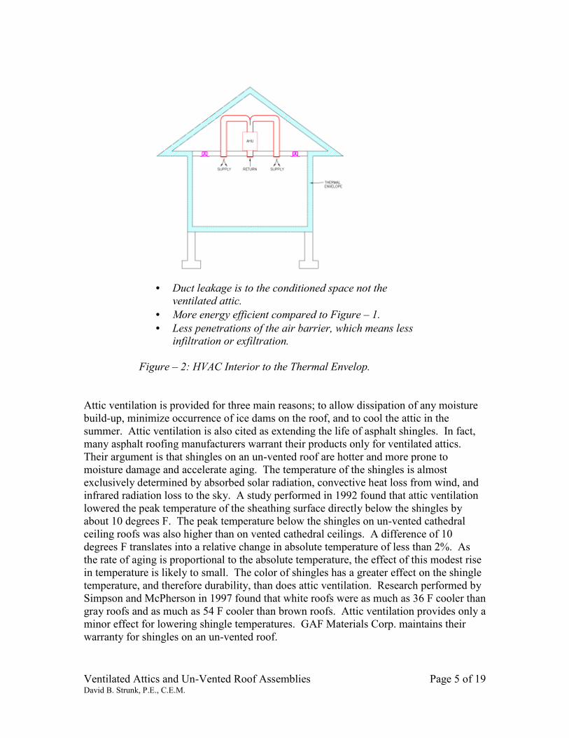
• Duct leakage is to the conditioned space not the ventilated attic.
• More energy efficient compared to Figure – 1. • Less penetrations of the air barrier, which means less
infiltration or exfiltration.
Figure – 2: HVAC Interior to the Thermal Envelop.
Attic ventilation is provided for three main reasons; to allow dissipation of any moisture
build-up, minimize occurrence of ice dams on the roof, and to cool the attic in the
summer. Attic ventilation is also cited as extending the life of asphalt shingles. In fact,
many asphalt roofing manufacturers warrant their products only for ventilated attics.
Their argument is that shingles on an un-vented roof are hotter and more prone to
moisture damage and accelerate aging. The temperature of the shingles is almost
exclusively determined by absorbed solar radiation, convective heat loss from wind, and
infrared radiation loss to the sky. A study performed in 1992 found that attic ventilation
lowered the peak temperature of the sheathing surface directly below the shingles by
about 10 degrees F. The peak temperature below the shingles on un-vented cathedral
ceiling roofs was also higher than on vented cathedral ceilings. A difference of 10
degrees F translates into a relative change in absolute temperature of less than 2%. As
the rate of aging is proportional to the absolute temperature, the effect of this modest rise
in temperature is likely to small. The color of shingles has a greater effect on the shingle
temperature, and therefore durability, than does attic ventilation. Research performed by
Simpson and McPherson in 1997 found that white roofs were as much as 36 F cooler than
gray roofs and as much as 54 F cooler than brown roofs. Attic ventilation provides only a
minor effect for lowering shingle temperatures. GAF Materials Corp. maintains their
warranty for shingles on an un-vented roof.
Ventilated Attics and Un-Vented Roof Assemblies Page 6 of 19 David B. Strunk, P.E., C.E.M.
Design Objectives:
The elimination of air movement is the main objective when designing a roof or attic to
be free of moisture problems, reduce ice dams, and control heat transfer. This is
accomplished by the proper installation of an air barrier with a ventilated attic or un-
vented roof assembly.
Vapor diffusion is the transfer of moisture in vapor form independent of air movement. It
is caused by differences in vapor pressure. Vapor in higher humidity areas want to move
to a lower humidity area. Incorporation of vapor barriers to control vapor diffusion is of
secondary importance and often not needed if air movement is controlled. Except in
Climate Zones 6 & 7 where a vapor retarder is recommended on the conditioned side of
the assembly.
Climate Regions:
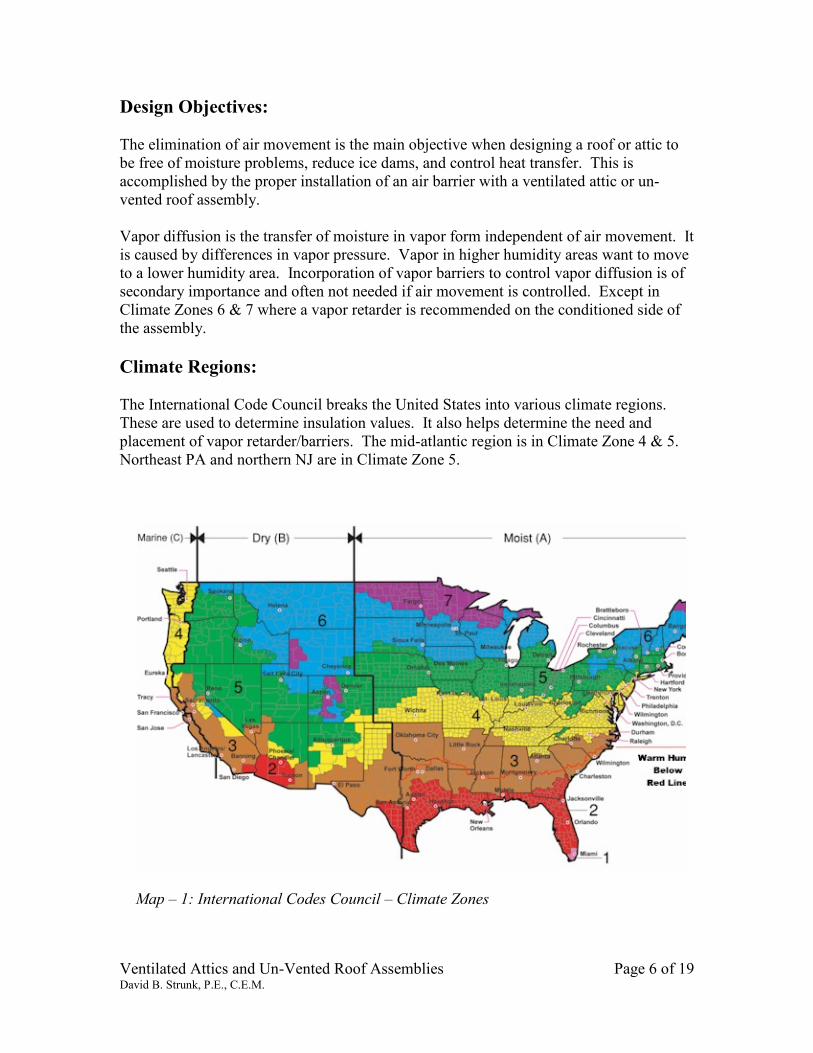
The International Code Council breaks the United States into various climate regions.
These are used to determine insulation values. It also helps determine the need and
placement of vapor retarder/barriers. The mid-atlantic region is in Climate Zone 4 & 5.
Northeast PA and northern NJ are in Climate Zone 5.
Map – 1: International Codes Council – Climate Zones
Ventilated Attics and Un-Vented Roof Assemblies Page 7 of 19 David B. Strunk, P.E., C.E.M.
Residential Code:
It is just of recent years that the un-vented option has been researched and allowed by
model building codes. The 2009 International Residential Code (IRC) states the
requirements for both ventilated attics and un-vented roof assemblies.
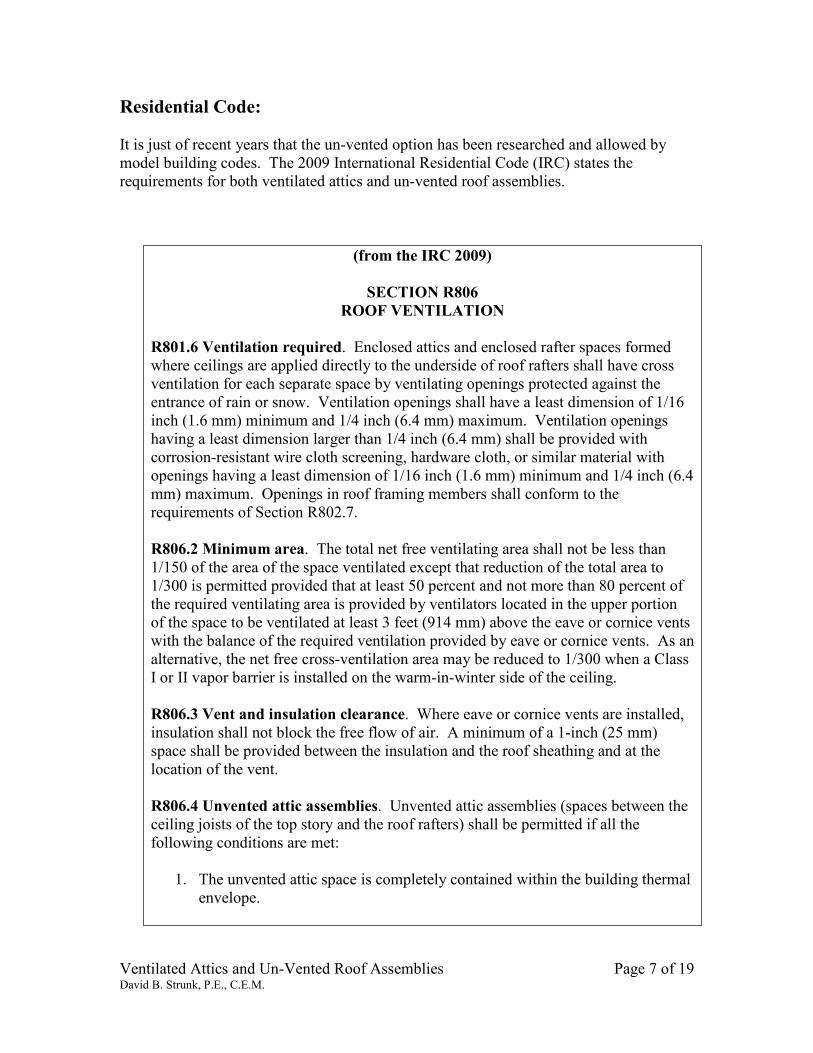
(from the IRC 2009)
SECTION R806
ROOF VENTILATION
R801.6 Ventilation required. Enclosed attics and enclosed rafter spaces formed
where ceilings are applied directly to the underside of roof rafters shall have cross
ventilation for each separate space by ventilating openings protected against the
entrance of rain or snow. Ventilation openings shall have a least dimension of 1/16
inch (1.6 mm) minimum and 1/4 inch (6.4 mm) maximum. Ventilation openings
having a least dimension larger than 1/4 inch (6.4 mm) shall be provided with
corrosion-resistant wire cloth screening, hardware cloth, or similar material with
openings having a least dimension of 1/16 inch (1.6 mm) minimum and 1/4 inch (6.4
mm) maximum. Openings in roof framing members shall conform to the
requirements of Section R802.7.
R806.2 Minimum area. The total net free ventilating area shall not be less than
1/150 of the area of the space ventilated except that reduction of the total area to
1/300 is permitted provided that at least 50 percent and not more than 80 percent of
the required ventilating area is provided by ventilators located in the upper portion
of the space to be ventilated at least 3 feet (914 mm) above the eave or cornice vents
with the balance of the required ventilation provided by eave or cornice vents. As an
alternative, the net free cross-ventilation area may be reduced to 1/300 when a Class
I or II vapor barrier is installed on the warm-in-winter side of the ceiling.
R806.3 Vent and insulation clearance. Where eave or cornice vents are installed,
insulation shall not block the free flow of air. A minimum of a 1-inch (25 mm)
space shall be provided between the insulation and the roof sheathing and at the
location of the vent.
R806.4 Unvented attic assemblies. Unvented attic assemblies (spaces between the
ceiling joists of the top story and the roof rafters) shall be permitted if all the
following conditions are met:
1. The unvented attic space is completely contained within the building thermal
envelope.
Ventilated Attics and Un-Vented Roof Assemblies Page 8 of 19 David B. Strunk, P.E., C.E.M.
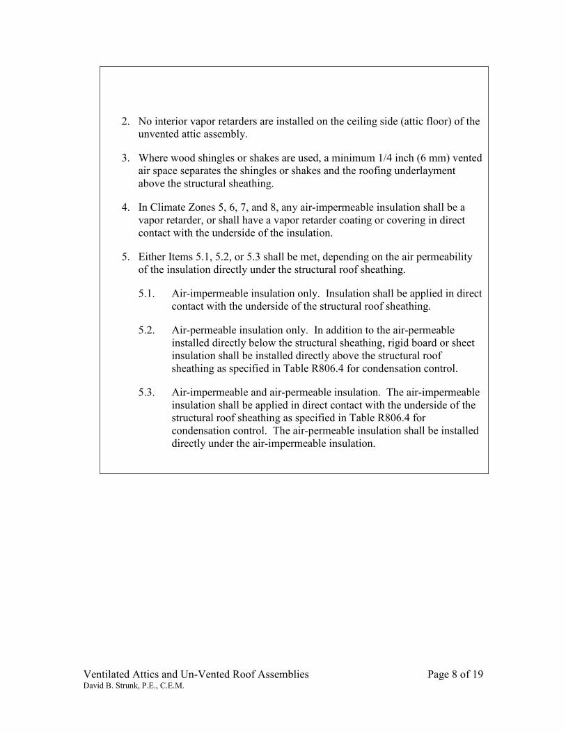
2. No interior vapor retarders are installed on the ceiling side (attic floor) of the
unvented attic assembly.
3. Where wood shingles or shakes are used, a minimum 1/4 inch (6 mm) vented
air space separates the shingles or shakes and the roofing underlayment
above the structural sheathing.
4. In Climate Zones 5, 6, 7, and 8, any air-impermeable insulation shall be a
vapor retarder, or shall have a vapor retarder coating or covering in direct
contact with the underside of the insulation.
5. Either Items 5.1, 5.2, or 5.3 shall be met, depending on the air permeability
of the insulation directly under the structural roof sheathing.
5.1. Air-impermeable insulation only. Insulation shall be applied in direct
contact with the underside of the structural roof sheathing.
5.2. Air-permeable insulation only. In addition to the air-permeable
installed directly below the structural sheathing, rigid board or sheet
insulation shall be installed directly above the structural roof
sheathing as specified in Table R806.4 for condensation control.
5.3. Air-impermeable and air-permeable insulation. The air-impermeable
insulation shall be applied in direct contact with the underside of the
structural roof sheathing as specified in Table R806.4 for
condensation control. The air-permeable insulation shall be installed
directly under the air-impermeable insulation.
Ventilated Attics and Un-Vented Roof Assemblies Page 9 of 19 David B. Strunk, P.E., C.E.M.
The International Building Code 2009 (IBC) does not address unvented attics. It is left
that attics require ventilation. However, local code officials have the ability to allow
unvented attics if asked. Given that they are allowed in the IRC there is strong argument
to allow them. It is the writers’ opinion that code will change in future versions to allow
unvented attics.
(from the IBC 2009)
SECTION 1203 Ventilation
1203.1 General. Buildings shall be provided with natural ventilation in accordance
with Section 1203.4, or mechanical ventilation in accordance with the International
Mechanical Code.
1203.2 Attic Spaces: Enclosed attic and enclosed rafter spaces formed where
ceilings are applied directly to the underside of roof framing members shall have
cross ventilation for each separate space by ventilating openings protected against
the entrance of rain and snow. Blocking and bridging shall be arranged so as not to
interfere with the movement of air. A minimum of 1 inch (25 mm) of airspace shall
be provided between the insulation and the roof sheathing. The net free ventilating
area shall not be less than 1/300 of the area of the space ventilated, with 50 percent
of the required ventilating area provided by ventilators located in the upper portion
of the space to be ventilated at least 3 feet (914 mm) above eave or cornice vents
with the balance of the required ventilation provided by eave or cornice vents.
Ventilated Attics and Un-Vented Roof Assemblies Page 10 of 19 David B. Strunk, P.E., C.E.M.
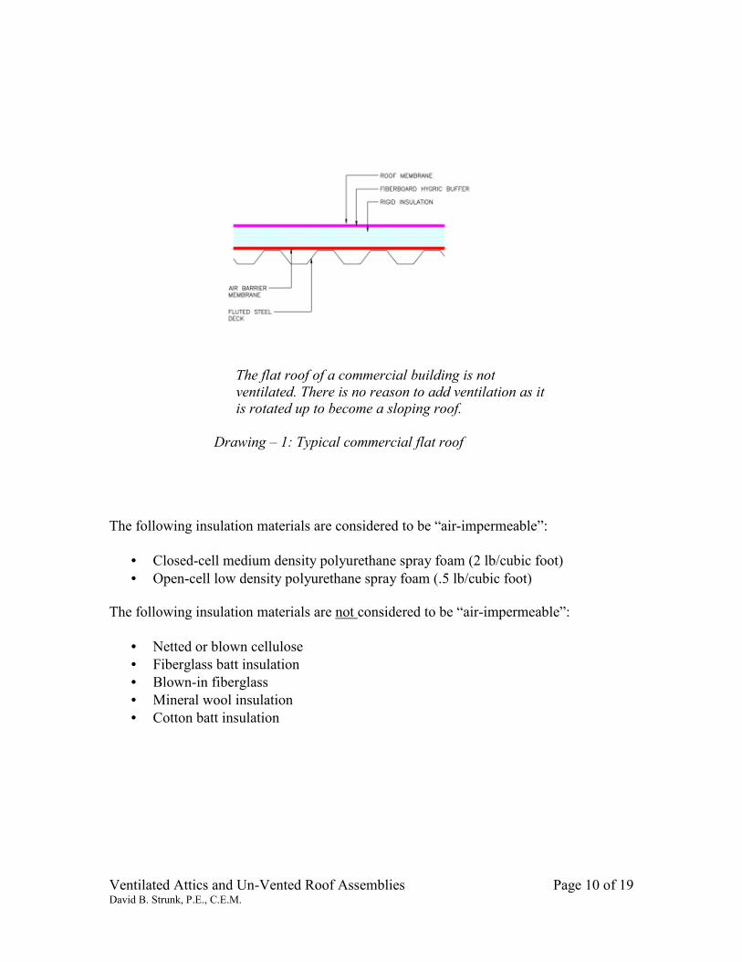
The flat roof of a commercial building is not
ventilated. There is no reason to add ventilation as it
is rotated up to become a sloping roof.
Drawing – 1: Typical commercial flat roof
The following insulation materials are considered to be “air-impermeable”:
• Closed-cell medium density polyurethane spray foam (2 lb/cubic foot)
• Open-cell low density polyurethane spray foam (.5 lb/cubic foot)
The following insulation materials are not considered to be “air-impermeable”:
• Netted or blown cellulose
• Fiberglass batt insulation
• Blown-in fiberglass
• Mineral wool insulation
• Cotton batt insulation
Ventilated Attics and Un-Vented Roof Assemblies Page 11 of 19 David B. Strunk, P.E., C.E.M.
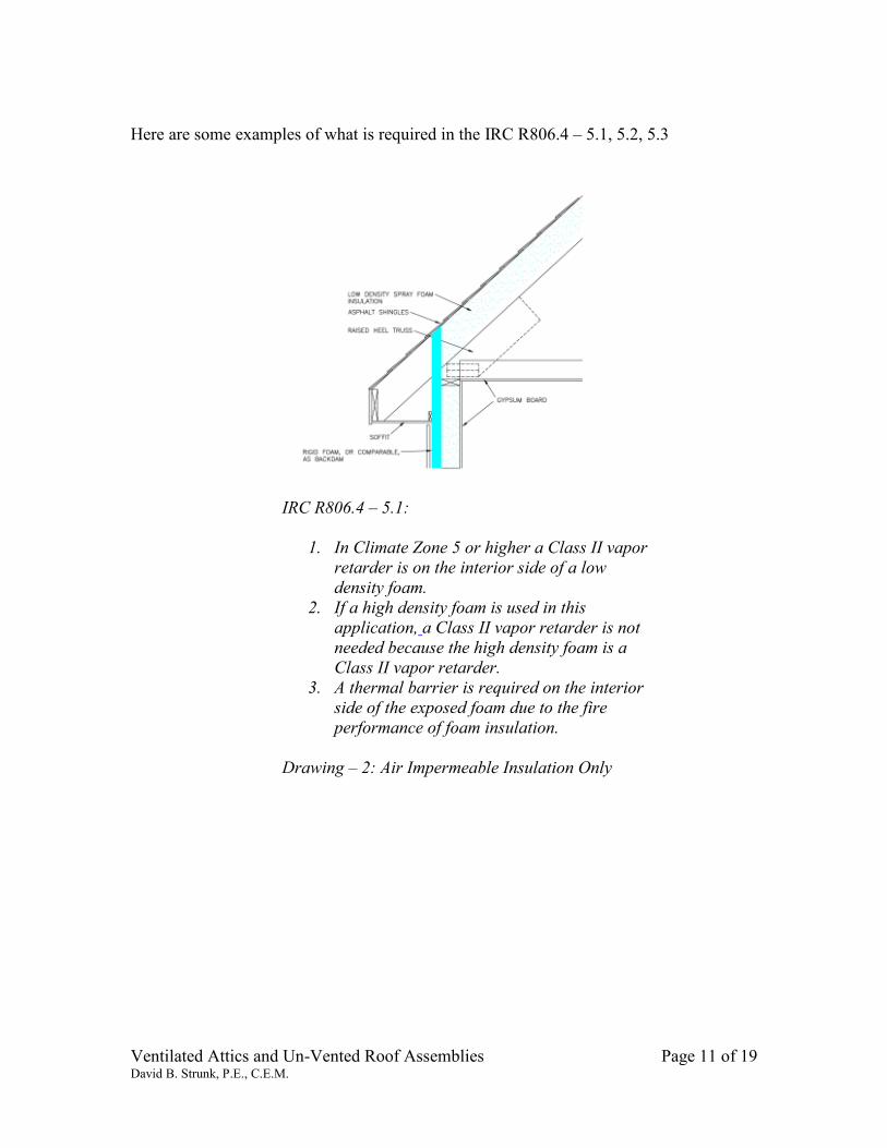
Here are some examples of what is required in the IRC R806.4 – 5.1, 5.2, 5.3
IRC R806.4 – 5.1:
1. In Climate Zone 5 or higher a Class II vapor
retarder is on the interior side of a low
density foam.
2. If a high density foam is used in this
application, a Class II vapor retarder is not
needed because the high density foam is a
Class II vapor retarder.
3. A thermal barrier is required on the interior
side of the exposed foam due to the fire
performance of foam insulation.
Drawing – 2: Air Impermeable Insulation Only
Ventilated Attics and Un-Vented Roof Assemblies Page 12 of 19 David B. Strunk, P.E., C.E.M.
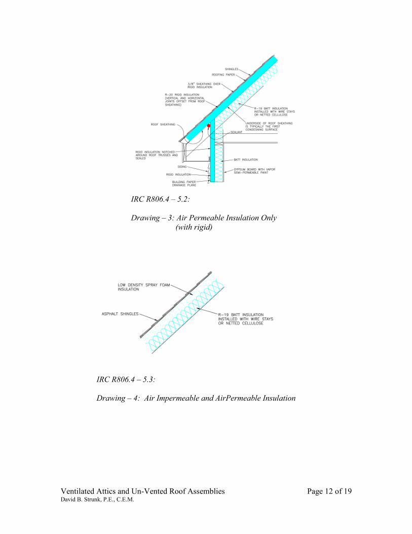
IRC R806.4 – 5.2:
Drawing – 3: Air Permeable Insulation Only
(with rigid)
IRC R806.4 – 5.3:
Drawing – 4: Air Impermeable and AirPermeable Insulation
Ventilated Attics and Un-Vented Roof Assemblies Page 13 of 19 David B. Strunk, P.E., C.E.M.
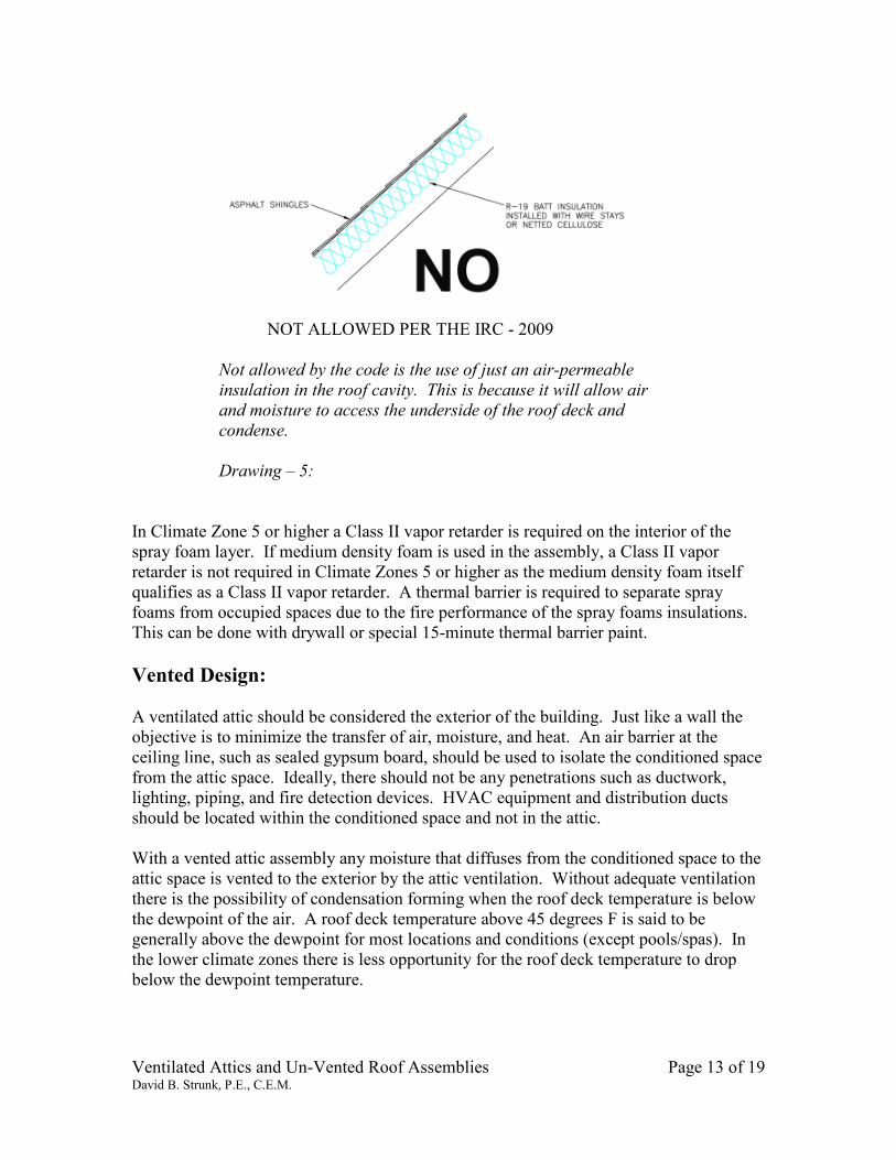
NOT ALLOWED PER THE IRC - 2009
Not allowed by the code is the use of just an air-permeable
insulation in the roof cavity. This is because it will allow air
and moisture to access the underside of the roof deck and
condense.
Drawing – 5:
In Climate Zone 5 or higher a Class II vapor retarder is required on the interior of the
spray foam layer. If medium density foam is used in the assembly, a Class II vapor
retarder is not required in Climate Zones 5 or higher as the medium density foam itself
qualifies as a Class II vapor retarder. A thermal barrier is required to separate spray
foams from occupied spaces due to the fire performance of the spray foams insulations.
This can be done with drywall or special 15-minute thermal barrier paint.
Vented Design:
A ventilated attic should be considered the exterior of the building. Just like a wall the
objective is to minimize the transfer of air, moisture, and heat. An air barrier at the
ceiling line, such as sealed gypsum board, should be used to isolate the conditioned space
from the attic space. Ideally, there should not be any penetrations such as ductwork,
lighting, piping, and fire detection devices. HVAC equipment and distribution ducts
should be located within the conditioned space and not in the attic.
With a vented attic assembly any moisture that diffuses from the conditioned space to the
attic space is vented to the exterior by the attic ventilation. Without adequate ventilation
there is the possibility of condensation forming when the roof deck temperature is below
the dewpoint of the air. A roof deck temperature above 45 degrees F is said to be
generally above the dewpoint for most locations and conditions (except pools/spas). In
the lower climate zones there is less opportunity for the roof deck temperature to drop
below the dewpoint temperature.
Ventilated Attics and Un-Vented Roof Assemblies Page 14 of 19 David B. Strunk, P.E., C.E.M.
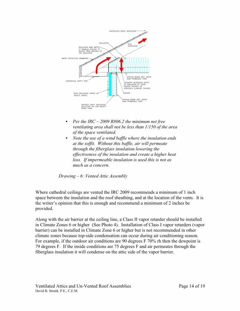
• Per the IRC – 2009 R806.2 the minimum net free ventilating area shall not be less than 1/150 of the area
of the space ventilated.
• Note the use of a wind baffle where the insulation ends at the soffit. Without this baffle, air will permeate
through the fiberglass insulation lowering the
effectiveness of the insulation and create a higher heat
loss. If impermeable insulation is used this is not as
much as a concern.
Drawing – 6: Vented Attic Assembly
Where cathedral ceilings are vented the IRC 2009 recommends a minimum of 1 inch
space between the insulation and the roof sheathing, and at the location of the vents. It is
the writer’s opinion that this is enough and recommend a minimum of 2 inches be
provided.
Along with the air barrier at the ceiling line, a Class II vapor retarder should be installed
in Climate Zones 6 or higher (See Photo 4). Installation of Class I vapor retarders (vapor
barrier) can be installed in Climate Zone 6 or higher but is not recommended in other
climate zones because top-side condensation can occur during air conditioning season.
For example, if the outdoor air conditions are 90 degrees F 70% rh then the dewpoint is
79 degrees F. If the inside conditions are 75 degrees F and air permeates through the
fiberglass insulation it will condense on the attic side of the vapor barrier.
Ventilated Attics and Un-Vented Roof Assemblies Page 15 of 19 David B. Strunk, P.E., C.E.M.
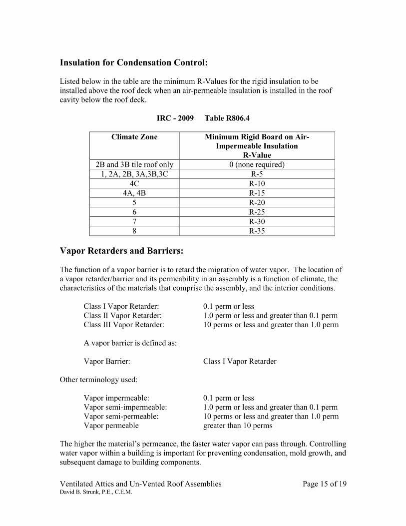
Insulation for Condensation Control:
Listed below in the table are the minimum R-Values for the rigid insulation to be
installed above the roof deck when an air-permeable insulation is installed in the roof
cavity below the roof deck.
IRC - 2009 Table R806.4
Climate Zone Minimum Rigid Board on Air-
Impermeable Insulation
R-Value
2B and 3B tile roof only 0 (none required)
1, 2A, 2B, 3A,3B,3C R-5
4C R-10
4A, 4B R-15
5 R-20
6 R-25
7 R-30
8 R-35
Vapor Retarders and Barriers:
The function of a vapor barrier is to retard the migration of water vapor. The location of
a vapor retarder/barrier and its permeability in an assembly is a function of climate, the
characteristics of the materials that comprise the assembly, and the interior conditions.
Class I Vapor Retarder: 0.1 perm or less
Class II Vapor Retarder: 1.0 perm or less and greater than 0.1 perm
Class III Vapor Retarder: 10 perms or less and greater than 1.0 perm
A vapor barrier is defined as:
Vapor Barrier: Class I Vapor Retarder
Other terminology used:
Vapor impermeable: 0.1 perm or less
Vapor semi-impermeable: 1.0 perm or less and greater than 0.1 perm
Vapor semi-permeable: 10 perms or less and greater than 1.0 perm
Vapor permeable greater than 10 perms
The higher the material’s permeance, the faster water vapor can pass through. Controlling
water vapor within a building is important for preventing condensation, mold growth, and
subsequent damage to building components.
Ventilated Attics and Un-Vented Roof Assemblies Page 16 of 19 David B. Strunk, P.E., C.E.M.
A 1/2-lb foam ranges between 6 perms and 10 perms, with a 3-in. thickness of material.
Its high permeability allows for diffusion of water vapor. 2-lb foam typically has a
permeance of less than 1 perm at 3-in., and can be used without a vapor retarder.
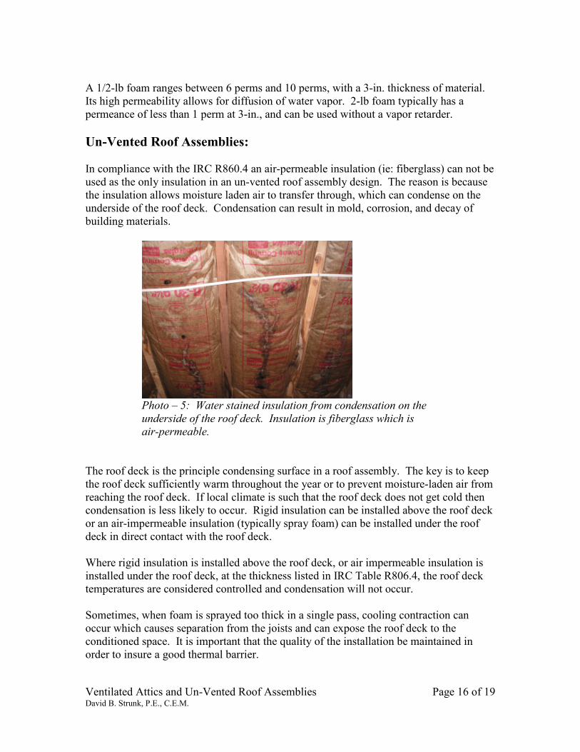
Un-Vented Roof Assemblies:
In compliance with the IRC R860.4 an air-permeable insulation (ie: fiberglass) can not be
used as the only insulation in an un-vented roof assembly design. The reason is because
the insulation allows moisture laden air to transfer through, which can condense on the
underside of the roof deck. Condensation can result in mold, corrosion, and decay of
building materials.
Photo – 5: Water stained insulation from condensation on the
underside of the roof deck. Insulation is fiberglass which is
air-permeable.
The roof deck is the principle condensing surface in a roof assembly. The key is to keep
the roof deck sufficiently warm throughout the year or to prevent moisture-laden air from
reaching the roof deck. If local climate is such that the roof deck does not get cold then
condensation is less likely to occur. Rigid insulation can be installed above the roof deck
or an air-impermeable insulation (typically spray foam) can be installed under the roof
deck in direct contact with the roof deck.
Where rigid insulation is installed above the roof deck, or air impermeable insulation is
installed under the roof deck, at the thickness listed in IRC Table R806.4, the roof deck
temperatures are considered controlled and condensation will not occur.
Sometimes, when foam is sprayed too thick in a single pass, cooling contraction can
occur which causes separation from the joists and can expose the roof deck to the
conditioned space. It is important that the quality of the installation be maintained in
order to insure a good thermal barrier.
Ventilated Attics and Un-Vented Roof Assemblies Page 17 of 19 David B. Strunk, P.E., C.E.M.
Examples of proper designs for un-vented roof assemblies are shown in Drawings 2, 3, &
4. These designs are suitable for standard residential and light commercial applications
where winter humidity levels are low. They should not be used where humidity levels
are high such as an indoor pool or spa enclosures.
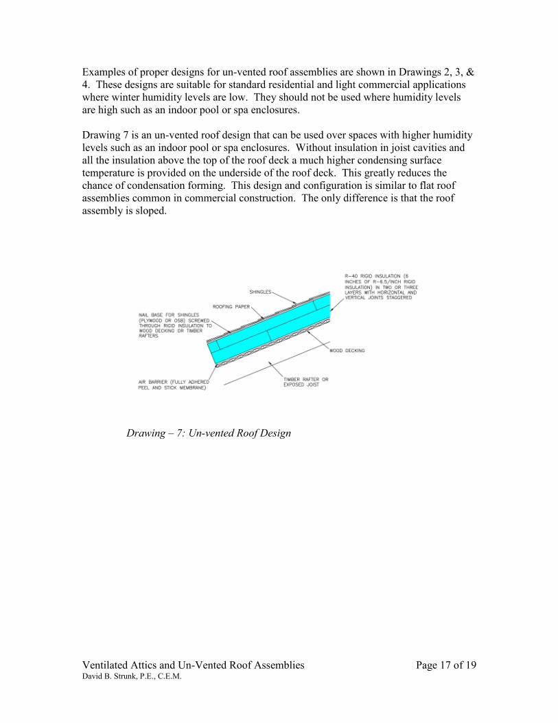
Drawing 7 is an un-vented roof design that can be used over spaces with higher humidity
levels such as an indoor pool or spa enclosures. Without insulation in joist cavities and
all the insulation above the top of the roof deck a much higher condensing surface
temperature is provided on the underside of the roof deck. This greatly reduces the
chance of condensation forming. This design and configuration is similar to flat roof
assemblies common in commercial construction. The only difference is that the roof
assembly is sloped.
Drawing – 7: Un-vented Roof Design
Ventilated Attics and Un-Vented Roof Assemblies Page 18 of 19 David B. Strunk, P.E., C.E.M.
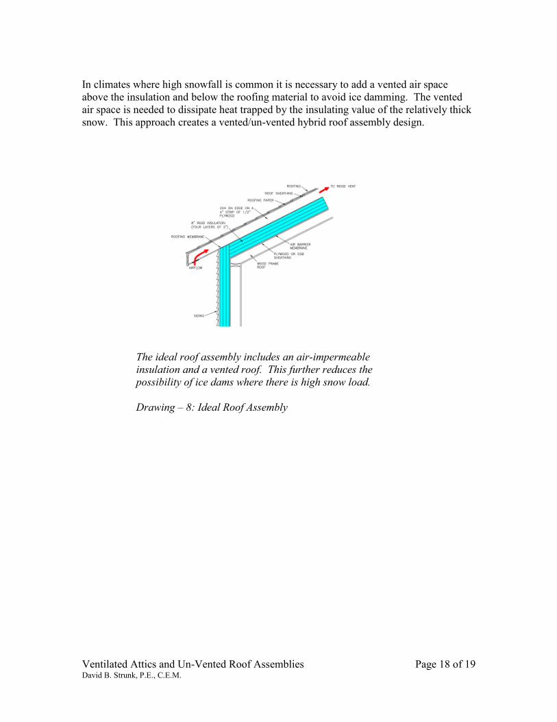
In climates where high snowfall is common it is necessary to add a vented air space
above the insulation and below the roofing material to avoid ice damming. The vented
air space is needed to dissipate heat trapped by the insulating value of the relatively thick
snow. This approach creates a vented/un-vented hybrid roof assembly design.
The ideal roof assembly includes an air-impermeable
insulation and a vented roof. This further reduces the
possibility of ice dams where there is high snow load.
Drawing – 8: Ideal Roof Assembly

Ventilated Attics and Un-Vented Roof Assemblies Page 19 of 19 David B. Strunk, P.E., C.E.M.
Summary:
Vented and un-vented attic/roof designs can be used in all hygro-thermal climate zones.
However the design of either depends on the climate zone and humidity levels inside the
conditioned space. Control of ice dams, heat gain, and moisture transfer can be
successfully accommodated by both vented and un-vented attic/roof designs. The choice
of the venting approach is up to the designer. With complex roof designs the unvented
approach may be easier and more successful.
It is true that the vented attic design has worked well in many buildings over the years,
but there are also conditions when it is not successful. This type of design works best
when the air barrier is tight with little or no penetrations and the mechanical equipment is
located in the conditioned space, not in the ventilated attic.
What has become common practice of installing mechanical equipment in the attic,
creating numerous penetrations of the air barrier, or no air barrier, uses more energy than
properly designed ventilated attic or an unvented attic.
References:
1. Lstiburek, Joseph, Building Science Corp. ASHRAE Journal April 2006.
“Understanding Attic Ventilation.”
2. Lstiburek, Joseph, Building Science Corp. July 2007. “Unvented Roof
Assemblies for All Climates.”
3. Rose and TenWolde, ASHRAE Journal October 2002. “Venting Of Attics
and Cathedral Ceiling.”
4. www.buildingscience.com