Embed Size (px)
Citation preview
VENICE Client Software User Guide (Version 1.5)
Video Server Control Software
VENICEClient Software
User Guide

2
1
3
I
4
5
A
6
VENICE Client Software User Guide
Introduction
Basics
Playing Out Clips
Recording Clips
Transcoding Clips
Miscellaneous
Appendix
Index
User Guide Version 1.5 for the VENICE Client Software Version 1.5
Copyright © 2010 by DVS Digital Video Systems AG, Hanover. All rights reserved.
The manuals as well as the soft- and/or hardware described here and all their constituent parts are protected by copyright. Without the express permission of DVS Digital Video Systems AG any form of use which goes beyond the narrow bounds prescribed by copyright legislation is prohibited and liable to prosecution.
This particularly applies to duplication, copying, translation, processing, evaluation, publishing, and storing and/or processing in an electronic system.
Specifications and data may change without notice. We offer no guarantee that this documentation is correct and/or complete. In no event shall DVS Digital Video Systems AG be liable for any dam-ages whatsoever (including without limitation any special, indirect or consequential damages, and damages resulting from loss of use, data or profits, or business interruption) arising out of the use of or inability to use the hardware, software and/or manual materials.
Those parts of this documentation that describe optional software or hardware features usually contain a corresponding note. Anyway, a lack of this note does not mean any commitment from DVS Digital Video Systems AG.
DVS and Spycer are registered trademarks of DVS Digital Video Systems AG. Apple, Mac and Mac OS are trademarks of Apple Inc., registered in the U.S. and other countries. Kodak and Cineon are trademarks of Eastman Kodak Company. Linux is a registered trademark of Linus Torvalds. Mi-crosoft and Windows are registered trademarks or trademarks of Microsoft Corporation in the Unit-ed States and/or other countries. Sony is a trademark of Sony Corporation.
Any other product names mentioned in this documentation may be trademarks or registered trade-marks of their respective owners and as such are subject to the usual statutory provisions.
Headquarters:
Support:
For the Americas:
Support:
DVS Digital Video Systems AGKrepenstr. 830165 HannoverGERMANY
Phone: +49-511-67807-0
Fax: +49-511-630070
E-mail: [email protected]
Internet: http://www.dvs.de
Phone: +49-511-67807-125
Fax: +49-511-371985
E-mail: [email protected]
U.S. Headquarters:
DVS Digital Video, Inc.300 East Magnolia Boulevard, Suite 102Burbank, CA 91502USA
Phone: +1-818-846-3600
Fax: +1-818-846-3648
E-mail: [email protected]
Internet: http://www.dvsus.com
E-mail: [email protected]

i
CContents
1 Introduction ............................................................................... 1-1
1.1 Overview ............................................................................. 1-2
1.2 Target Group ........................................................................ 1-3
1.3 Conventions Used in this User Guide .................................... 1-3
1.4 Important Notes ................................................................... 1-5
2 Basics .......................................................................................... 2-1
2.1 Starting the Program ............................................................ 2-22.1.1 Starting the Software under Linux ................................. 2-22.1.2 Starting the Software under Mac OS ............................. 2-22.1.3 Starting the Software under Windows ........................... 2-2
2.2 General Usage of the Software ............................................. 2-32.2.1 Connecting to the VENICE Server ................................. 2-42.2.2 Selecting a Project ....................................................... 2-52.2.3 Selecting the Operation Mode ...................................... 2-52.2.4 Configuring the Operation Mode .................................. 2-62.2.5 Performing the Operation ............................................ 2-7
2.3 Slave Mode .......................................................................... 2-92.3.1 Slave Mode Control Window in Playout Mode ............... 2-92.3.2 Slave Mode Control Window in Ingest Mode ............... 2-10
2.4 Locking the User Interface .................................................. 2-11
2.5 Disconnecting and Freeing a Video Channel ....................... 2-12
2.6 Preconfiguring the VENICE Client Software ........................ 2-132.6.1 Presets ..................................................................... 2-132.6.2 Projects .................................................................... 2-142.6.3 Playlists / Transcoding Lists ......................................... 2-142.6.4 Metaclips ................................................................. 2-15
2.7 Exiting the Program............................................................ 2-15
ii
VENICE Client Software User Guide
2.8 About Timecode / Frame Number Fields............................. 2-16
2.9 About Audio....................................................................... 2-18
2.10 About Source Timecode...................................................... 2-19
3 Playing Out Clips ..................................................................... 3-1
3.1 Configuring a Play-out ......................................................... 3-23.1.1 Selecting Content for Play-out ...................................... 3-23.1.2 Selecting Essences for Play-out ..................................... 3-63.1.3 Configuring the Output Settings ................................... 3-7
3.2 The Video Overlay ............................................................... 3-9
3.3 The Scrub Bar / Shuttle Bar................................................. 3-113.3.1 The Scrub Bar ........................................................... 3-113.3.2 The Shuttle Bar ......................................................... 3-11
3.4 Information Area ................................................................ 3-13
3.5 Controlling the Devices (Player / Recorder) ........................ 3-143.5.1 Player Controls (VENICE) ........................................... 3-143.5.2 Recorder Controls ..................................................... 3-143.5.3 The Controls Explained .............................................. 3-15
3.6 Playing Out with the VENICE Server ................................... 3-193.6.1 How to Play Out Clips Manually ................................. 3-193.6.2 How to Crash Record with the External Device ............. 3-203.6.3 How to Autoedit Record with the External Device ......... 3-213.6.4 How to Perform a Play-out in Slave Mode.................... 3-23
4 Recording Clips ......................................................................... 4-1
4.1 Configuring a Record ........................................................... 4-24.1.1 Configuring the Input Settings ...................................... 4-24.1.2 Selecting Essences for Record........................................ 4-34.1.3 Configuring the Output Settings (File Settings) ............... 4-44.1.4 Selecting the Storage Location and File Name ................. 4-54.1.5 The Captured Files....................................................... 4-7
4.2 The Video Overlay ............................................................... 4-9
4.3 The Shuttle Bar ................................................................... 4-10
4.4 Information Area ................................................................ 4-10
4.5 Controlling the Devices (Player / Recorder) ........................ 4-114.5.1 Player Controls ......................................................... 4-114.5.2 Recorder Controls (VENICE) ....................................... 4-114.5.3 The Controls Explained .............................................. 4-12
iii
Contents
4.6 Recording with the VENICE Server ..................................... 4-134.6.1 How to Control the External Device ............................ 4-134.6.2 How to Crash Record with the VENICE Server .............. 4-144.6.3 How to Autoedit Record with the VENICE Server .......... 4-154.6.4 How to Perform a Slave Mode Record ......................... 4-17
5 Transcoding Clips ..................................................................... 5-1
5.1 Controls Available for a Transcoding ..................................... 5-25.1.1 Configuration Items..................................................... 5-25.1.2 Player Controls ........................................................... 5-3
5.2 Transcoding with the VENICE Server .................................... 5-5
6 Miscellaneous ........................................................................... 6-1
6.1 Playlist / Transcoding List Editor ........................................... 6-26.1.1 Using Playlists / Transcoding Lists .................................. 6-26.1.2 Displaying the List Editor .............................................. 6-36.1.3 Adding Items to a List .................................................. 6-36.1.4 General Administration ................................................ 6-46.1.5 Administering a List ..................................................... 6-46.1.6 The Context Menus..................................................... 6-6
6.2 Audio Monitoring ................................................................. 6-86.2.1 Displaying the Audio Monitoring Tool ............................ 6-86.2.2 Using the Audio Monitoring Tool .................................. 6-9
6.3 The Menus ......................................................................... 6-106.3.1 The ’File’ Menu......................................................... 6-106.3.2 The ’Options’ Menu .................................................. 6-116.3.3 The ’Help’ Menu ....................................................... 6-12
A Appendix ....................................................................................A-1
A.1 Keyboard Shortcuts ..............................................................A-1
A.2 Supported File Formats .........................................................A-3
A.3 States of an External Device .................................................A-7
I Index ............................................................................................ I-1

iv
VENICE Client Software User Guide
1-1
1
1
2
3
4
5
I
A
6
Introduction
This document describes how to use the software delivered with VENICE, the multi-channel video server manufactured by DVS.
VENICE is a highly flexible server system for the capturing and play-out of audio and video content. Especially designed for broadcast work-flows, it provides multiple independent channels and supports natively the most common compressed formats. With VENICE you can easily capture live content, e.g. from cameras directly, and access data for play-out operations – if required both at the same time and in the for-mat that suits your workflow best. During each operation you can con-trol an externally connected device via RS-422 to act as a player or recorder, either in a manual or autoedit operation mode.
To control the hardware of VENICE the VENICE client software is re-quired. It is a comprehensive and intuitive application that can be used either on the server locally (Linux version) or on any network client (Linux, Mac, Windows) connected to the server. With this you can place the hardware of VENICE at any location you like and still have full control over it. By opening several instances of the software you can control different video channels of one or more VENICE servers at the same time.
1-2
VENICE Client Software User Guide
1.1 Overview
This user guide informs you about the general handling of the VENICE software as well as about its complete controllable interface.
The chapters in this user guide contain the following information:
Chapter 1 Begins with a short introduction to VENICE and its software, followed by a note regarding the audience this manual is written for and an ex-planation of the conventions used in this man-ual. Furthermore, it provides some important notes that you should observe.
Chapter 2 This chapter contains basic information about the VENICE client software. In addition to the information how to start and exit the program, this chapter describes the steps to get started with the software in the sequence as they should be carried out. Additionally, this chapter provides some general useful notes.
Chapter 3 Describes how to play out clips with the VENICE client software.
Chapter 4 How to record clips with the VENICE client software is described in this chapter.
Chapter 5 Describes how to transcode clips with the VENICE client software.
Chapter 6 Provides information about the tools, for ex-ample, to administer playlists/transcoding lists or to adapt the streamed audio heard at your workstation. Furthermore, the menu bar and its options will be explained.
Appendix Gives additional information about the soft-ware. Among others you can find here lists of the available keyboard shortcuts and the sup-ported file formats.
Index This chapter facilitates the search for specific terms.
1-3
Introduction
1
2
3
4
5
I
A
6
1.2 Target Group
To use this user guide and the DVS software correctly you should have experience in handling PCs and working with the respective operating system where the software is installed. If you want to use the software and the DVS system to its full potential, you should also have knowl-edge in the field of digital video in general.
When working with the hardware of VENICE you should be familiar with the hardware handling of a video/server system.
Furthermore, to use the DVS system in connection with other equip-ment, e.g. a VTR, you should know how to operate this equipment.
1.3 Conventions Used in this User Guide
The following typographical conventions will be used in this documen-tation:
Texts preceded by this symbol describe activities that you must per-form in the order indicated.
– Texts preceded by this symbol are parts of a list.
Texts preceded by this symbol are general notes intended to fa-cilitate work and help avoid errors.
You must pay particular attention to text that follows this symbol to avoid errors.
“ ” Texts enclosed by quotation marks are references to other man-uals, guides, chapters, or sections.
BUTTON Text in small caps and bold indicates push but-tons
Menu Text in italic and bold indicates either a menu name or options in a menu list
Menu » Option In the specified menu select the stated item
Item Text in bold only stands for other labeled items of a user interface
Directory/File Directory structure or file
Entry Parameters, selections or entries made in the program; it may also indicate a command (e.g. at a command line), file syntax or contents of a file
1-4
VENICE Client Software User Guide
Keyboard Shortcuts
To perform options or procedures with the keyboard often requires a si-multaneous pressing of two keys.
Example:
Screenshots
The screenshots shown in this documentation were taken for the most part from the Windows-based version of the VENICE client software. Depending on the operating system where the software is installed, their appearance may differ from your environment. However, they should contain the relevant elements that you need to understand the described actions.
[Key] An individual key or a key combination on a keyboard
[Ctrl + F1] If this is given, hold down the [Ctrl] key and press simultaneously the [F1] key.
1-5
Introduction
1
2
3
4
5
I
A
6
1.4 Important Notes
To use the VENICE software correctly please heed the following:
On the DVS system only use the designated video drive (main storage) to store video and audio data. Other storage locations will be too slow for real-time operations.
Leave about 15 % of the overall main storage capacity empty of data for real-time performance reasons.
The real-time capability of the DVS system depends to a large extent on the performance of the system’s hardware. There-fore, it is recommended to terminate all other programs on the DVS system while working with VENICE.
Your DVS system has been tested thoroughly and is very reli-able. However, because of the vast amount of third-party software available, its reactions on the installation of such could not be tested. The installation of third-party software on the DVS system may disrupt the real-time capability and/or limit the functionality of your system.
For any data management with the VENICE client software the latest Spycer application by DVS must be installed as well (see the “VENICE Administration and Configuration” user guide for further information).
On Linux operating systems the display suspend mode will be disabled when the VENICE client software is installed and it must remain disabled.
1-6
VENICE Client Software User Guide
2-1
2
2
1
3
4
5
I
A
6
Basics
This chapter provides you with basic information about the VENICE cli-ent software. In addition to the information how to start the program, this chapter describes the basic operation steps to get started with the VENICE client software in the sequence as they should be carried out. This will be followed by an explanation of how to free the video chan-nel again for other users and how to shut down the program. Further-more, this chapter provides some general notes useful when working with the software.
2-2
VENICE Client Software User Guide
2.1 Starting the Program
This section provides you with a description how to get the VENICE cli-ent software started. You can run several instances of the software in parallel on the same system, for example, to connect to different video channels of a VENICE server.
2.1.1 Starting the Software under Linux
To get the software started under the Linux operating system perform the following:
Select from the system menu of Linux the entry Audio & Video » VENICE.Alternatively, you may also start the program from a command line (terminal) by entering Venice.
This will load the VENICE client software by DVS (see section “General Usage of the Software” on page 2-3) and you can start working with it (see section “Connecting to the VENICE Server” on page 2-4).
2.1.2 Starting the Software under Mac OS
To get the software started under Mac OS perform the following:
Select from the Applications folder of Mac OS the entry VENICE.app.
This will load the VENICE client software by DVS (see section “General Usage of the Software” on page 2-3) and you can start working with it (see section “Connecting to the VENICE Server” on page 2-4).
2.1.3 Starting the Software under Windows
To get the software started under the Windows operating system per-form the following:
Select from the START button menu of Windows on the submenu DVS the entry for the DVS software (for example, All Programs » DVS » DVS VENICE).Alternatively, you may also start the program via the VENICE icon on the desktop of Windows.
This will load the VENICE client software by DVS (see section “General Usage of the Software” on page 2-3) and you can start working with it (see section “Connecting to the VENICE Server” on page 2-4).
2-3
Basics
2
1
3
4
5
I
A
6
2.2 General Usage of the Software
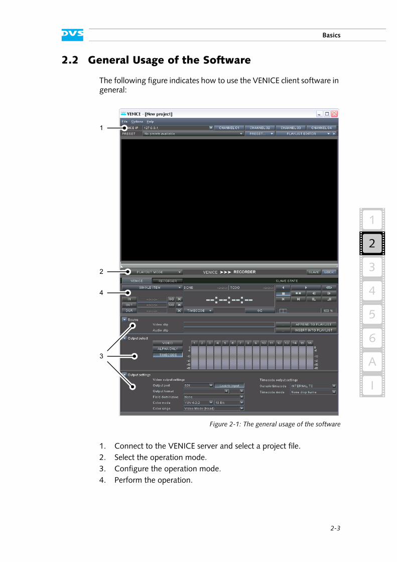
The following figure indicates how to use the VENICE client software in general:
Figure 2-1: The general usage of the software
1. Connect to the VENICE server and select a project file.2. Select the operation mode.3. Configure the operation mode.4. Perform the operation.
1
4
2
3
2-4
VENICE Client Software User Guide
All steps are explained in more detail in the following.
2.2.1 Connecting to the VENICE Server
The channel connection settings at the top of the user interface are used to establish a connection to the VENICE server. This step is the first to start working with the VENICE server. It has to be made with the lo-cally installed user interface as well as with a remote installed one.
With the channel connection settings you connect to the VENICE server and allocate one of its video channels. Once a connection is successfully established, you have full control over this channel and you can use it, for example, for a play-out operation.
Figure 2-2: The channel connection settings
To connect to one of the video channels of the VENICE server perform the following:
Enter in the entry field VENICE IP: the IP address of the VENICE server that you want to connect to or select an address from its drop-down list.
Then click on the respective channel button to request this video channel from the server.
By clicking on a channel button the connection will be established: First the VENICE server with the specified IP address is contacted. Then it tries to allocate the requested video channel. When both steps are suc-cessful, the clicked video channel button will be displayed in its activat-ed state, otherwise you will receive an appropriate error message (e.g. ’Cannot connect to server …’ or ’Device already in use’).
Via project files or presets the software can be preconfigured for certain tasks. Then it may not be necessary to perform all the steps described below (see section “Preconfiguring the VENICE Client Software” on page 2-13).
With one instance of the VENICE client software you can con-trol one video channel. To control other video channels at the same time you can start the software multiple times.
Once a connection is successfully established, the respective channel (device) is in use. To connect to this particular video channel, for example, from another VENICE client software, it must be freed first (see section “Disconnecting and Freeing a Video Channel” on page 2-12).
2-5
Basics
2
1
3
4
5
I
A
6
2.2.2 Selecting a Project
After the successful connection to a video channel a window with the recently used projects will be displayed. The last ten project files will be listed:
Figure 2-3: Selecting a project
With a click of the mouse on a project file it can be loaded into the VENICE client software. You can also start a new project (button NEW PROJECT) or load one that is not shown in the list (button LOAD PROJECT…).
Once a project has been loaded or started anew, you can begin working with the VENICE server by choosing one of its operation modes.
2.2.3 Selecting the Operation Mode
After connecting to the VENICE server you can select between the dif-ferent operation modes for the VENICE server:
Figure 2-4: Selecting the operation mode
Select the desired operation mode from the drop-down list of the operation mode combo box. You can choose between an INGEST MODE, a PLAYOUT MODE and a TRANSCODE MODE.
For further information about project files see section “Projects” on page 2-14.
2-6
VENICE Client Software User Guide
In the TRANSCODE MODE you can convert video and audio material to different file formats. If possible, the file conversion will be per-formed in hardware at a faster render speed. Further information about it can be found in chapter “Transcoding Clips” on page 5-1.
When PLAYOUT MODE or INGEST MODE has been selected, the VENICE server assumes the role either of the player or of the recorder. The opposing role can be performed by an externally connected device:
The direction of the selected operation mode and the role of the VENICE server as well as of the external device is reflected to the right of the operation mode combo box:
Figure 2-5: Direction indication of operation mode
After the operation mode has been selected, it has to be configured properly for the desired task.
2.2.4 Configuring the Operation Mode
Prior to performing an operation with VENICE you have to configure the selected operation mode. The configurations for the operation modes can be found at the bottom of the user interface:
Operation Mode Role of VENICE Role of External Device
playout mode player recorder
ingest mode recorder player
Whether the player or the recorder controls are currently acti-vated is indicated in blue (see section “Controlling the Devices (Player / Recorder)” on page 3-14 and section “Controlling the Devices (Player / Recorder)” on page 4-11). A device that is currently recording will be displayed in red.
playout mode:
ingest mode:
VENICE is player and external device is recorder
VENICE is recorder and external device is player
playout mode configurations (collapsed):
2-7
Basics
2
1
3
4
5
I
A
6
Figure 2-6: Operation mode configurations
When the configurations are collapsed they show you, as space per-mits, their settings in a single line in text form (e.g. for the output set-tings of the playout mode: SDI; 1920 × 1080p 24 SMPTE274; 16:9; YUV 4:2:2; 10 Bit ...). With a click on the buttons showing a triangle to the left the respective settings items can be ex-panded or collapsed.
Use the configuration items to configure the selected operation mode. Further information about this can be found in section “Configuring a Play-out” on page 3-2, section “Configuring a Record” on page 4-2 or section “Configuration Items” on page 5-2.
Once the selected operation mode is configured properly, you can start using the VENICE server.
2.2.5 Performing the Operation
With the player/recorder controls you can start the desired operation. In the playout or ingest mode the VENICE server can be controlled as well as an externally connected device, each according to its role deter-mined by the chosen operation mode (see section “Configuring the
With the context menu invoked on a triangle button all settings can be expanded or collapsed in a single step (depending on the state of the triangle button).
Figure 2-7: Context menu to show/hide all settings
See also section “The ’Options’ Menu” on page 6-11.
ingest mode configurations (collapsed):
transcode mode configurations (collapsed):
2-8
VENICE Client Software User Guide
Operation Mode” on page 2-6). The device that should be controlled can be selected with the tabs above the controls:
Figure 2-8: The player/recorder controls
Set up the operation by, for example, determining in- and outpoints for the operation.
Then start the desired operation. Further information about all this can be found in chapter “Playing Out Clips” on page 3-1, chapter “Recording Clips” on page 4-1 or chapter “Transcoding Clips” on page 5-1.
Once the operation is complete and your task is finished, you can stop your work with the VENICE server at any time. For this you have to dis-connect and free the video channel so that others can use it for their work. This is described in section “Disconnecting and Freeing a Video Channel” on page 2-12.
tabsplayout mode:
ingest mode:
transcode mode:
2-9
Basics
2
1
3
4
5
I
A
6
2.3 Slave Mode
The VENICE server usually operates as a master. Nevertheless, in the playout and ingest mode (see section “Selecting the Operation Mode” on page 2-5) it can be used as a slave via RS-422 as well. Then the VENICE server can be controlled by an external device.
With the combo box to the left of the button SLAVE the RS-422 pro-tocol that should be used to control the VENICE server in slave mode can be selected. You can select between the Sony 9-pin protocol or VDCP.
Then the slave mode can be activated by pressing the SLAVE button:
Figure 2-9: Slave mode
After this commands for record, play, stop, jog, or shuttle can be sent via RS-422 and will be carried out by the VENICE server depending on the selected operation mode. It will behave like a VTR using preroll, postroll, etc. The specifications of these parameters can be found in the “VENICE Administration and Configuration” user guide.
Normally when in slave mode, the video channel can no longer be con-trolled with the VENICE client software, only the master can control it. To enable minimal control of the channel without relinquishing the slave mode, control windows are provided. They are described shortly in the following.
2.3.1 Slave Mode Control Window in Playout Mode
In the playout mode the following slave mode control window will be displayed:
Figure 2-10: Slave mode control (playout mode)
2-10
VENICE Client Software User Guide
It provides the same items as available for a control of the player. For a description of them see section “Player Controls (VENICE)” on page 3-14. Additionally the following items are available:
2.3.2 Slave Mode Control Window in Ingest Mode
In the ingest mode the following slave mode control window will be displayed:
Figure 2-11: Slave mode control (ingest mode)
It provides the items as described below:
REMOTE PROTOCOL
Select from the REMOTE PROTOCOL combo box the RS-422 protocol that should be used to control the VENICE server. You can select between the Sony 9-pin protocol or VDCP.
For VDCP an output path has to be de-fined. Further information about this can be found in the “VENICE Administration and Configuration” user guide.
This button allows you to open the VENICE con-figurations. You can then change, for example, RS-422 relevant settings. See “VENICE Adminis-tration and Configuration” user guide.
This button deactivates the slave mode and closes the slave mode control window.
REMOTE PROTOCOL
Select from the REMOTE PROTOCOL combo box the RS-422 protocol that should be used to control the VENICE server. Currently only the Sony 9-pin protocol can be selected.
This button allows you to open the VENICE config-urations. You can then change, for example, RS-422 relevant settings.
2-11
Basics
2
1
3
4
5
I
A
6
2.4 Locking the User Interface
To make sure that the currently running task does not accidentally get interrupted you can lock the user interface of the software. For this ac-tivate the button LOCK to the right of the operation mode settings:
Figure 2-12: The button ’LOCK’
Then all items of the user interface will be dimmed and unavailable, and the connected video channel will continue with the task that was initi-ated previously.
As a safety precaution, with the user interface locked you cannot un-lock it again with one of its items. To unlock it you have to press the key combination [Ctrl + L] on the keyboard.
This field shows you the position of the record. When a record is in progress the numbers will be displayed in red.
With this button you can start a record operation. Then the button changes its appearance to its ac-tive state and the capturing begins immediately. To terminate a record, you have to click this button again.
This button deactivates the slave mode and closes the slave mode control window.
2-12
VENICE Client Software User Guide
2.5 Disconnecting and Freeing a Video Channel
When your work with the VENICE client software is finished, the allo-cated video channel should be freed again so that other users will be able to use it for their tasks. If a video channel is not freed again, it will remain occupied by this instance of the VENICE client software, and no one else can connect to it (error message ’Device already in use’).
To free a video channel for others perform one of the following:
1. Click once more on the respective video channel button, i.e. the activated one.
This will deactivate the button whereupon the connection to the video channel of the VENICE server is severed and the channel will be freed.
2. Alternatively, you can close this instance of the VENICE client soft-ware (see section “Exiting the Program” on page 2-15).
When the program is closed, the connection to the video channel of the VENICE server is severed and the channel will be freed.
A freeing/disconnection of the video channels can be forced at the VENICE server. Further information about this can be found in the “VENICE Administration and Configuration” user guide.
2-13
Basics
2
1
3
4
5
I
A
6
2.6 Preconfiguring the VENICE Client Software
The VENICE client software can be preconfigured for often recurring tasks so that operators are not required to do this time and again during their work. It is up to the management/administrator to decide how de-tailed this preconfiguration should be. They have to prepare the files and the operator has to act accordingly.
The VENICE client software offers various files that can be used for a preconfiguration and they are described in this section. All files can be saved and loaded whenever required.
2.6.1 Presets
Via presets you can easily set up the VENICE client software for often recurring tasks, such as records from a particular device in a certain file/video format or play-outs of prepared VENICE playlists in a particular format. Presets store the complete layout of the software (e.g. opera-tion mode and state of the user interface) as well as the configuration settings, i.e. they store everything but content (e.g. IP addresses, clip names, paths, or other presets).
These files are normally stored locally where the VENICE client software is running, but can be transferred easily between systems by copying/moving their files and can then be used immediately.
Presets can be created and administered with the items below the chan-nel connection settings at the top of the user interface:
Figure 2-13: The items to handle presets
With the combo box to the left you can select already created/loaded presets.
With the combo box PRESET… to the right presets can be adminis-tered. It provides the following possibilities:
File extension: *.vprst Preset file
Save preset… Saves the currently set layout and configura-tions as a preset to a file.
Load preset… Loads a stored preset from a file. Afterwards it can be selected from the drop-down list of the combo box to the left.
2-14
VENICE Client Software User Guide
2.6.2 Projects
VENICE project files can be used to make a complete snapshot of the current state of a VENICE client software. In other words they store ev-erything that is saved via presets (see section “Presets” on page 2-13) and, furthermore, store content as well.
These files are normally stored locally where the VENICE client software is running, but can be transferred easily between systems by copying/moving their files and can then be used immediately.
Projects are administered via the File menu of the menu bar. For further information about it see section “The ’File’ Menu” on page 6-10.
When connecting to a video channel of the VENICE server, a window will be displayed showing you the recently used projects. Then you can select one for loading or start a new one (see section “Selecting a Project” on page 2-5).
2.6.3 Playlists / Transcoding Lists
With the VENICE client software you can create lists that can be used for a play-out as well as a transcoding. They can be created and admin-istered either with the playlist or the transcoding list editor (see section “Playlist / Transcoding List Editor” on page 6-2). There you can add any number of video and audio clips in any sequence you like. It is also possible to link video to audio clips so that they are used together, and to have VENICE metaclips as clips/items on the list. Via the controls you can select whether you want to operate on a single item or a complete list.
These files are normally stored locally where the VENICE client software is running, but can be transferred easily between systems by copying/moving their files and can then be used immediately.
Delete preset Deletes the preset that is currently selected with the combo box to the left from its drop-down list. However, the corresponding preset file is not deleted.
Delete all presets Deletes all presets from the drop-down list of the combo box to the left. The corresponding preset files are not deleted.
File extension: *.venice Project file
File extension: *.vplst Playlist/transcoding list file
2-15
Basics
2
1
3
4
5
I
A
6
2.6.4 Metaclips
VENICE metaclips are used as a container for video and audio clips. They are normal text files that detail among others the location of the included clips.
During a record with VENICE, metaclips are created automatically and stored on the main storage same as the actual data (see section “The Captured Files” on page 4-7). They can also be created via the list ed-itors of the VENICE client software (see section “Playlist / Transcoding List Editor” on page 6-2). For play-out, transcoding, playlists, or transcoding lists VENICE metaclips can be specified just as any other clip.
Normally one video and one or more audio clips are described in a metaclip. However, it is also possible to reference to several video/au-dio clips in a metaclip and they would be played out successively as list-ed in the metaclip.
2.7 Exiting the Program
To end a running instance of the VENICE client software perform the following:
Select the option Exit on the File menu (Mac: VENICE » Quit VENICE) or press the key combination [Alt + F4] or [Ctrl + Q] (Mac: [ + Q]) alternatively.
This will close the instance of the VENICE client software. In case a con-nection to a video channel is currently established, the connection will be severed (see also section “Disconnecting and Freeing a Video Chan-nel” on page 2-12).
File extension: *.vamc Video/audio metaclip file
2-16
VENICE Client Software User Guide
2.8 About Timecode / Frame Number Fields
The DVS software provides various fields where data in timecode for-mat is provided or an entry in such a format is necessary. The timecode format is hh:mm:ss:ff (hours, minutes, seconds, and frame num-ber).
Drop-frame Timecode Indication
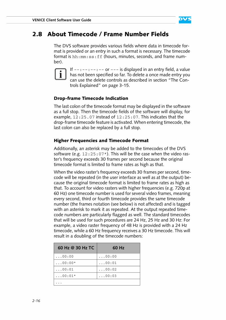
The last colon of the timecode format may be displayed in the software as a full stop. Then the timecode fields of the software will display, for example, 12:25.07 instead of 12:25:07. This indicates that the drop-frame timecode feature is activated. When entering timecode, the last colon can also be replaced by a full stop.
Higher Frequencies and Timecode Format
Additionally, an asterisk may be added to the timecodes of the DVS software (e.g. 12:25:07*). This will be the case when the video ras-ter’s frequency exceeds 30 frames per second because the original timecode format is limited to frame rates as high as that.
When the video raster’s frequency exceeds 30 frames per second, time-code will be repeated (in the user interface as well as at the output) be-cause the original timecode format is limited to frame rates as high as that. To account for video rasters with higher frequencies (e.g. 720p at 60 Hz) one timecode number is used for several video frames, meaning every second, third or fourth timecode provides the same timecode number (the frames notation (see below) is not affected) and is tagged with an asterisk to mark it as repeated. At the output repeated time-code numbers are particularly flagged as well. The standard timecodes that will be used for such procedures are 24 Hz, 25 Hz and 30 Hz: For example, a video raster frequency of 48 Hz is provided with a 24 Hz timecode, while a 60 Hz frequency receives a 30 Hz timecode. This will result in a doubling of the timecode numbers:
If --:--:--:-- or --- is displayed in an entry field, a value has not been specified so far. To delete a once made entry you can use the delete controls as described in section “The Con-trols Explained” on page 3-15.
60 Hz @ 30 Hz TC 60 Hz
...00:00 ...00:00
...00:00* ...00:01
...00:01 ...00:02
...00:01* ...00:03
...
2-17
Basics
2
1
3
4
5
I
A
6
At even higher frame rates (e.g. 90 Hz) the timecode numbers will be tripled, quadrupled etc., making a timecode handling of all common frequencies possible.
Entering Timecode
When entering timecode in one of the software’s position or length in-dicators, it is not necessary to type in the timecode separators (colons). Simply place the cursor at the appropriate position (e.g. at the minute numbers) and enter the timecode numbers from there. After pressing [Enter] on your keyboard or selecting another item of the user interface the entered timecode is accepted in the respective timecode field.
When you enter a timecode value that exceeds the raster’s frequency, the timecode will be recalculated (e.g. 00:00:02:47 will be set to 00:00:03:23 if raster is in 24 Hz). When entering a timecode value that exceeds the boundaries of the available timeline, it will be set to the lowest/highest possible value.
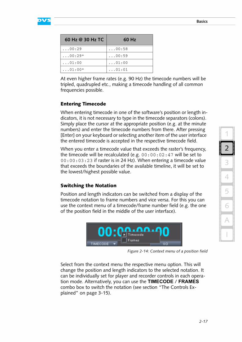
Switching the Notation
Position and length indicators can be switched from a display of the timecode notation to frame numbers and vice versa. For this you can use the context menu of a timecode/frame number field (e.g. the one of the position field in the middle of the user interface).
Figure 2-14: Context menu of a position field
Select from the context menu the respective menu option. This will change the position and length indicators to the selected notation. It can be individually set for player and recorder controls in each opera-tion mode. Alternatively, you can use the TIMECODE / FRAMES combo box to switch the notation (see section “The Controls Ex-plained” on page 3-15).
...00:29 ...00:58
...00:29* ...00:59
...01:00 ...01:00
...01:00* ...01:01
60 Hz @ 30 Hz TC 60 Hz
2-18
VENICE Client Software User Guide
2.9 About Audio
The DVS software provides a full support of audio during record or play-out operations. Up to 16 different channels of audio can be in- or output by the system. The audio data can be accessed and processed in the software as easily as the video material.
When performing a record operation, the audio data can be input ei-ther embedded in the video signal (audio in video, AIV) or via the sep-arate digital audio connectors. You may have both signals connected to the DVS system and prior to a record you have to specify the type of signal that the system has to capture (see section “Configuring the In-put Settings” on page 4-2). However, for an input of audio data a sam-pling rate of 48 kHz is supported only. In case you want to capture audio alone, a video signal has to be present at the system’s input and the video format settings have to be set accordingly. Regarding the cre-ated files, when no container format has been selected, you can choose between several file formats for the audio files (e.g. *.aiff or *.wav). Only one file per record will be written which will include all the selected audio channels (audio file containing multiple channels).
On the other hand, when performing a play-out operation, you do not have to configure the way a play-out of audio is performed. It will be played out simultaneously, embedded in the video signal (AIV) as well as via the digital audio output connectors.
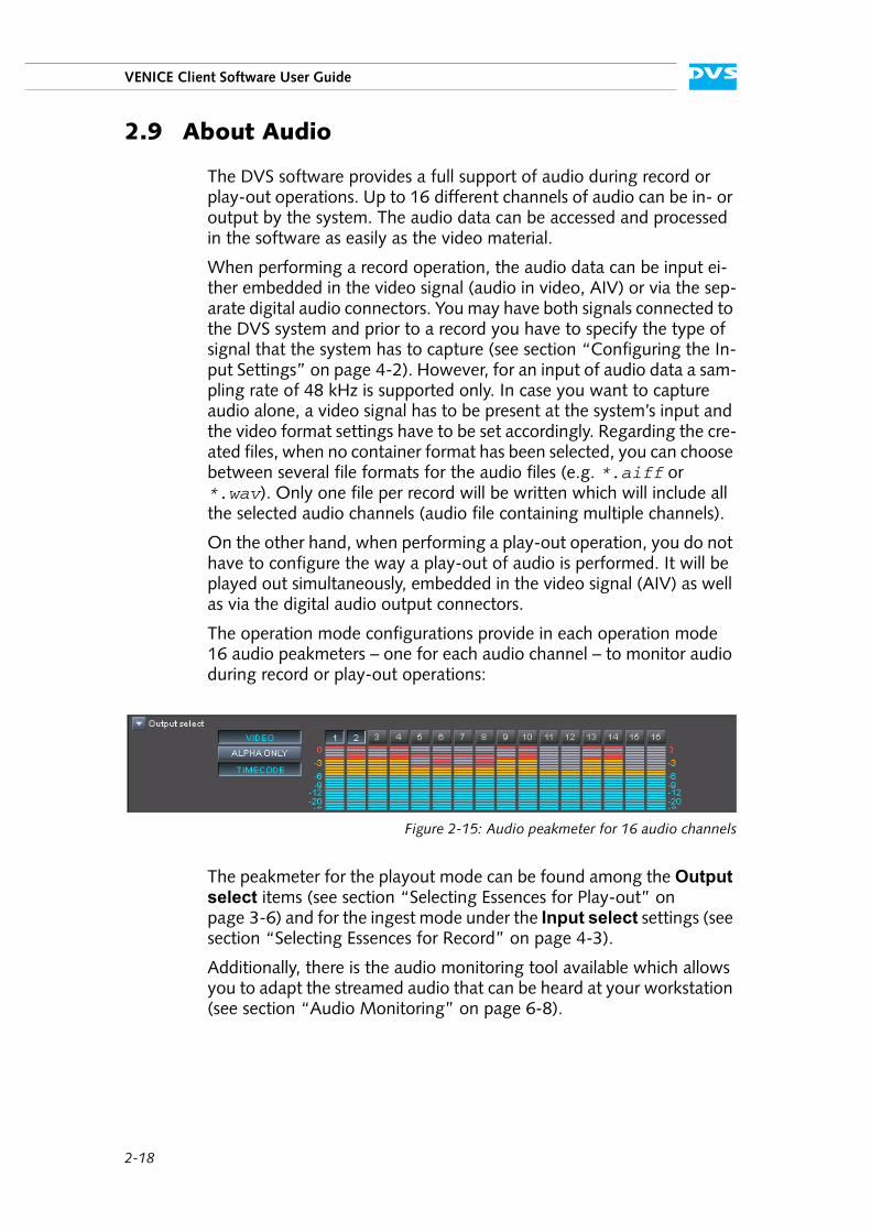
The operation mode configurations provide in each operation mode 16 audio peakmeters – one for each audio channel – to monitor audio during record or play-out operations:
Figure 2-15: Audio peakmeter for 16 audio channels
The peakmeter for the playout mode can be found among the Output select items (see section “Selecting Essences for Play-out” on page 3-6) and for the ingest mode under the Input select settings (see section “Selecting Essences for Record” on page 4-3).
Additionally, there is the audio monitoring tool available which allows you to adapt the streamed audio that can be heard at your workstation (see section “Audio Monitoring” on page 6-8).
2-19
Basics
2
1
3
4
5
I
A
6
2.10 About Source Timecode
Some file formats for clips, e.g. *.dpx files, are capable of storing more information than just their image content. These information are usu-ally written in a specified format into the file headers which can be read and interpreted by different software applications that support these kind of information. Among the information stored you can find, for example, the name of the creator (usually the program that created the files), the creation time and date, and the timecode.
Most of the data stored in file headers and transmitted to the VENICE server during a capturing will only be recorded and given back again during a play-out, if appropriate. However, DVS especially makes use of the timecode information.
Timecode information stored in file headers (the so-called source time-code) can be used in the VENICE client software. For example, you can use clips that provide source timecodes during the play-out of a playlist and regardless of the current position they will always show their source timecode. Then, prior to a play-out you can decide whether the internal timecode should be given out as a timecode signal or the source time-codes provided by the files.
Normally, image files capable of storing timecode information provide space for one timecode only in their header (generic source timecode). DVS systems, however, are able to receive (e.g. during a record) several timecodes incorporated in signals at various connectors. During a write procedure, i.e. when recording clips (*.dpx files), they will write the re-ceived timecode information into the file headers. The ones additionally received will be stored at a location for user defined data in the header and usually cannot be interpreted by applications other than the ones developed by DVS. When processing such clips afterwards, for in-stance, with another DVS system, you may select between the various timecodes provided by the clips which may give you more control over their position in a timeline.
The DVS software supports additional information such as source timecode in the *.dpx, *.mov as well as *.mxf and Broadcast Wave file formats. However, some features (e.g. multiple timecodes or the editing of header data) are available for *.dpx files only.
With the help of Spycer the header data, such as timecode or keycode information, can be adjusted to your liking (see “Spycer” user guide for more information).
Audio files equipped with source timecode usually provide a start timecode only. Subsequent timecodes will be calculated and drop-frame timecodes are currently not supported.
2-20
VENICE Client Software User Guide
3-1
3
3
2
1
4
5
I
A
6
Playing Out Clips
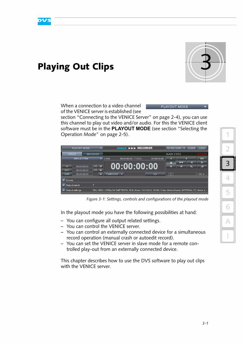
When a connection to a video channel of the VENICE server is established (see section “Connecting to the VENICE Server” on page 2-4), you can use this channel to play out video and/or audio. For this the VENICE client software must be in the PLAYOUT MODE (see section “Selecting the Operation Mode” on page 2-5).
Figure 3-1: Settings, controls and configurations of the playout mode
In the playout mode you have the following possibilities at hand:
– You can configure all output related settings.– You can control the VENICE server.– You can control an externally connected device for a simultaneous
record operation (manual crash or autoedit record).– You can set the VENICE server in slave mode for a remote con-
trolled play-out from an externally connected device.
This chapter describes how to use the DVS software to play out clips with the VENICE server.
3-2
VENICE Client Software User Guide
3.1 Configuring a Play-out
Prior to playing out clips with the VENICE server you have to set up the play-out and configure output related settings (see also section “Con-figuring the Operation Mode” on page 2-6). As a minimum you have to select content for a play-out. This section describes the necessary settings that have to be made before playing out clips with the VENICE server.
3.1.1 Selecting Content for Play-out
Before anything can be played out you have to determine the content for the output. By clicking on the triangle button to the left of the item Source, the necessary settings can be expanded (or collapsed):
Figure 3-2: Setting the source
There are several ways to select content for a play-out:
1. You can enter the respective paths and file names manually.2. You can select content via a dialog window.3. You can drag and drop the content from one of the browsing
panes of Spycer.
All these procedures will be explained in this section.
Entering Paths and File Names Manually
To select content for a play-out you can enter the respective paths and file names manually. Just start to enter something in the entry field for
Via project files or presets the software can be preconfigured for certain tasks. Then it may not be necessary to perform all the configurations described below (see section “Preconfigur-ing the VENICE Client Software” on page 2-13).
After a record operation with the VENICE server (see chapter “Recording Clips” on page 4-1), the metaclip of the recorded content will be automatically set for a play-out. With this you can review the captured material immediately after a record operation.
It is also possible to play out a playlist. Further information about playlists can be found in section “Playlists / Transcoding Lists” on page 2-14.
3-3
Playing Out Clips
3
2
1
4
5
I
A
6
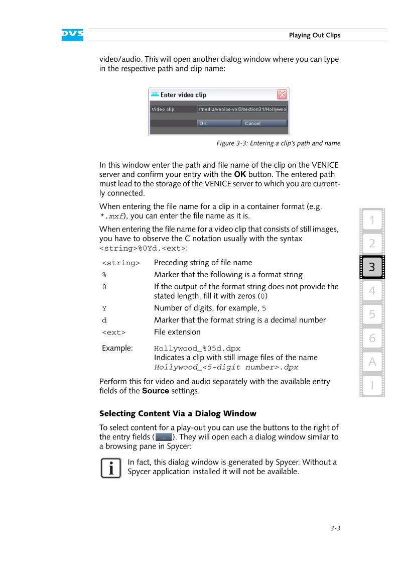
video/audio. This will open another dialog window where you can type in the respective path and clip name:
Figure 3-3: Entering a clip’s path and name
In this window enter the path and file name of the clip on the VENICE server and confirm your entry with the OK button. The entered path must lead to the storage of the VENICE server to which you are current-ly connected.
When entering the file name for a clip in a container format (e.g. *.mxf), you can enter the file name as it is.
When entering the file name for a video clip that consists of still images, you have to observe the C notation usually with the syntax <string>%0Yd.<ext>:
Perform this for video and audio separately with the available entry fields of the Source settings.
Selecting Content Via a Dialog Window
To select content for a play-out you can use the buttons to the right of the entry fields ( ). They will open each a dialog window similar to a browsing pane in Spycer:
<string> Preceding string of file name
% Marker that the following is a format string
0 If the output of the format string does not provide the stated length, fill it with zeros (0)
Y Number of digits, for example, 5
d Marker that the format string is a decimal number
<ext> File extension
Example: Hollywood_%05d.dpxIndicates a clip with still image files of the name Hollywood_<5-digit number>.dpx
In fact, this dialog window is generated by Spycer. Without a Spycer application installed it will not be available.
3-4
VENICE Client Software User Guide
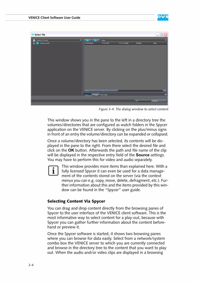
Figure 3-4: The dialog window to select content
This window shows you in the pane to the left in a directory tree the volumes/directories that are configured as watch folders in the Spycer application on the VENICE server. By clicking on the plus/minus signs in front of an entry the volume/directory can be expanded or collapsed.
Once a volume/directory has been selected, its contents will be dis-played in the pane to the right. From there select the desired file and click on the OK button. Afterwards the path and file name of the clip will be displayed in the respective entry field of the Source settings. You may have to perform this for video and audio separately.
Selecting Content Via Spycer
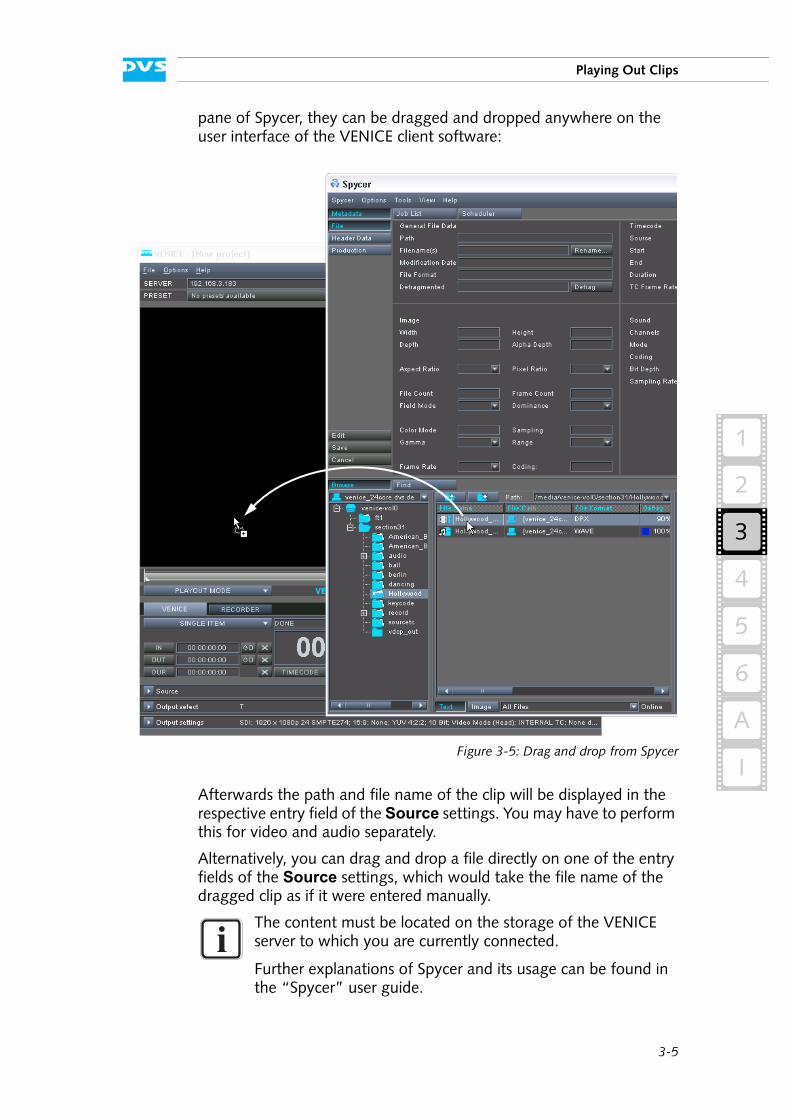
You can drag and drop content directly from the browsing panes of Spycer to the user interface of the VENICE client software. This is the most informative way to select content for a play-out, because with Spycer you can gather further information about the content before-hand or preview it.
Once the Spycer software is started, it shows two browsing panes where you can browse for data easily. Select from a network/system combo box the VENICE server to which you are currently connected and browse in the directory tree to the content that you want to play out. When the audio and/or video clips are displayed in a browsing
This window provides more items than explained here. With a fully licensed Spycer it can even be used for a data manage-ment of the contents stored on the server (via the context menus you can e.g. copy, move, delete, defragment, etc.). Fur-ther information about this and the items provided by this win-dow can be found in the “Spycer” user guide.
3-5
Playing Out Clips
3
2
1
4
5
I
A
6
pane of Spycer, they can be dragged and dropped anywhere on the user interface of the VENICE client software:
Figure 3-5: Drag and drop from Spycer
Afterwards the path and file name of the clip will be displayed in the respective entry field of the Source settings. You may have to perform this for video and audio separately.
Alternatively, you can drag and drop a file directly on one of the entry fields of the Source settings, which would take the file name of the dragged clip as if it were entered manually.
The content must be located on the storage of the VENICE server to which you are currently connected.
Further explanations of Spycer and its usage can be found in the “Spycer” user guide.
3-6
VENICE Client Software User Guide
3.1.2 Selecting Essences for Play-out
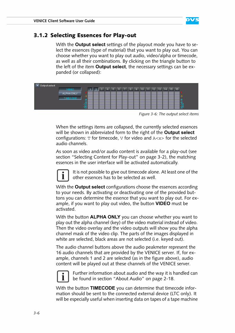
With the Output select settings of the playout mode you have to se-lect the essences (type of material) that you want to play out. You can choose whether you want to play out audio, video/alpha or timecode, as well as all their combinations. By clicking on the triangle button to the left of the item Output select, the necessary settings can be ex-panded (or collapsed):
Figure 3-6: The output select items
When the settings items are collapsed, the currently selected essences will be shown in abbreviated form to the right of the Output select configurations: T for timecode, V for video and A<x> for the selected audio channels.
As soon as video and/or audio content is available for a play-out (see section “Selecting Content for Play-out” on page 3-2), the matching essences in the user interface will be activated automatically.
With the Output select configurations choose the essences according to your needs. By activating or deactivating one of the provided but-tons you can determine the essence that you want to play out. For ex-ample, if you want to play out video, the button VIDEO must be activated.
With the button ALPHA ONLY you can choose whether you want to play out the alpha channel (key) of the video material instead of video. Then the video overlay and the video outputs will show you the alpha channel mask of the video clip. The parts of the images displayed in white are selected, black areas are not selected (i.e. keyed out).
The audio channel buttons above the audio peakmeter represent the 16 audio channels that are provided by the VENICE server. If, for ex-ample, channels 1 and 2 are selected (as in the figure above), audio content will be played out at these channels of the VENICE server.
With the button TIMECODE you can determine that timecode infor-mation should be sent to the connected external device (LTC only). It will be especially useful when inserting data on tapes of a tape machine
It is not possible to give out timecode alone. At least one of the other essences has to be selected as well.
Further information about audio and the way it is handled can be found in section “About Audio” on page 2-18.
3-7
Playing Out Clips
3
2
1
4
5
I
A
6
via the insert mode of the playout mode (see section “The Controls Ex-plained” on page 3-15). Then you can explicitly select that the LTC timecode should be given out with this button.
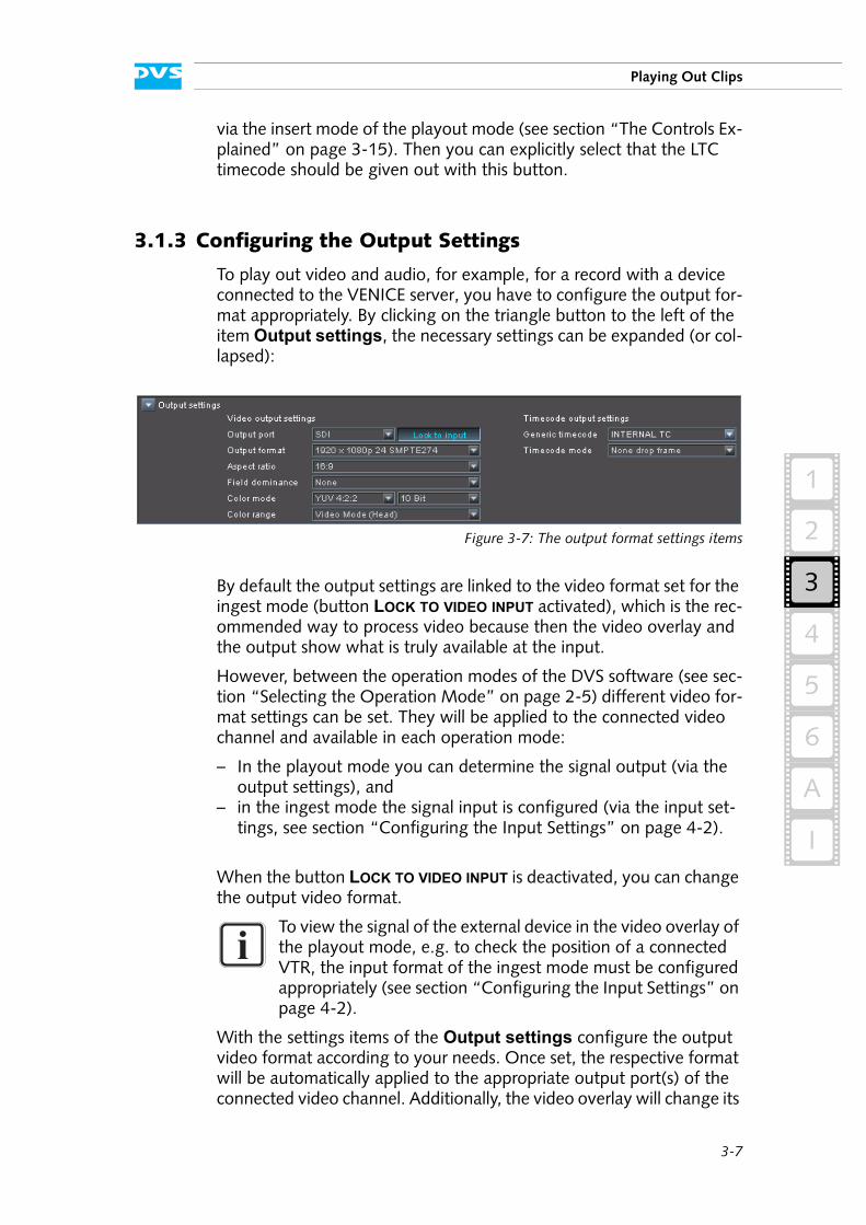
3.1.3 Configuring the Output Settings
To play out video and audio, for example, for a record with a device connected to the VENICE server, you have to configure the output for-mat appropriately. By clicking on the triangle button to the left of the item Output settings, the necessary settings can be expanded (or col-lapsed):
Figure 3-7: The output format settings items
By default the output settings are linked to the video format set for the ingest mode (button LOCK TO VIDEO INPUT activated), which is the rec-ommended way to process video because then the video overlay and the output show what is truly available at the input.
However, between the operation modes of the DVS software (see sec-tion “Selecting the Operation Mode” on page 2-5) different video for-mat settings can be set. They will be applied to the connected video channel and available in each operation mode:
– In the playout mode you can determine the signal output (via the output settings), and
– in the ingest mode the signal input is configured (via the input set-tings, see section “Configuring the Input Settings” on page 4-2).
When the button LOCK TO VIDEO INPUT is deactivated, you can change the output video format.
With the settings items of the Output settings configure the output video format according to your needs. Once set, the respective format will be automatically applied to the appropriate output port(s) of the connected video channel. Additionally, the video overlay will change its
To view the signal of the external device in the video overlay of the playout mode, e.g. to check the position of a connected VTR, the input format of the ingest mode must be configured appropriately (see section “Configuring the Input Settings” on page 4-2).
3-8
VENICE Client Software User Guide
format (e.g. its aspect ratio, see section “The Video Overlay” on page 3-9).
Furthermore, with the Output settings you can determine the time-code settings for the play-out.
The selected output raster is applied to the video overlay and it may have an effect on the images displayed there (e.g. they may get cropped). You can use the video overlay to see the ef-fects immediately.
Rasters for film not included in the SDI standard (i.e. 2K with 20 Hz or more) are output via the DVI outputs only.
3-9
Playing Out Clips
3
2
1
4
5
I
A
6
3.2 The Video Overlay
In the upper part of the user interface you can find the video overlay.
Figure 3-8: Video overlay
Depending on the selected device in the playout mode (see section “Controlling the Devices (Player / Recorder)” on page 3-14), you can use the video overlay either to view the input signal or to play out clips already available on the server:
– When the player controls are activated (VENICE), you can view the played out material.
– When the recorder controls are activated, you can view the input signal.
By using the player/recorder controls you can, for example, start a play-out or move within the displayed content.
The video overlay normally reflects what is present at the output of the VENICE server. Thus its layout (aspect ratio) is that of the currently set output video raster (see section “Configuring the Output Settings” on page 3-7). It may have an effect on the clip in the video overlay, for ex-
To view the signal from an externally connected device the input format must be set accordingly (see section “Config-uring the Input Settings” on page 4-2).
When controlling the video channel from a client, the images in the video overlay are transmitted via network. There may be a time delay until the material is displayed in the video overlay and it may seem as if drops occurred. Real drops on the server, however, will be automatically detected and you will be in-formed about them in the information area (see section “Infor-mation Area” on page 3-13).
3-10
VENICE Client Software User Guide
ample, the images may get cropped, and you can use the video overlay to see the effects immediately.
The context menu of the video overlay provides the following possibil-ities:
Figure 3-9: Context menu of the video overlay
Resize to default Resizes the user interface to its default size (see also section “The ’Options’ Menu” on page 6-11).
Reset dropped frames display
Resets the dropped frames counter (see also section “The ’Options’ Menu” on page 6-11).
3-11
Playing Out Clips
3
2
1
4
5
I
A
6
3.3 The Scrub Bar / Shuttle Bar
Beneath the video overlay you can find a bar. Depending on the device selected for the current operation mode (player/recorder), it can pro-vide either a scrub bar or a shuttle bar.
3.3.1 The Scrub Bar
The scrub bar will be available when the player controls (VENICE) are activated (see section “Controlling the Devices (Player / Recorder)” on page 3-14) and content is selected for a play-out (see section “Select-ing Content for Play-out” on page 3-2).
Figure 3-10: The scrub bar
The scrub bar provides a timeline of the currently selected content. With its cursor ( ) you can move within and view it. Simply select the cursor with the mouse and move it along the scrub bar to the de-sired position. You can also click somewhere on the scrub bar to move the scrub bar cursor there instantly. While working with the scrub bar or the player controls (see section “Player Controls (VENICE)” on page 3-14), the video overlay will always adjust to your moves on the timeline of the selected content (see section “The Video Overlay” on page 3-9).
The blue line indicates the part of the timeline that is currently selected via in- and outpoint.
3.3.2 The Shuttle Bar
The shuttle bar is used to control an externally connected device via RS-422. It will be available when the recorder controls (external device) are activated (see section “Controlling the Devices (Player / Recorder)” on page 3-14) and the external device is set to accept remote control.
Figure 3-11: The shuttle bar
Use the slider of the shuttle bar to perform fast backward or forward operations. The slider will shuttle back to its zero position when dragged with the mouse and then released. Drag the slider to the left or right to move back- or forward in the video material of the player. The farther you drag it, the faster the play-out will be. While dragging,
3-12
VENICE Client Software User Guide
the slider allows for a continuous setting of the speed in either direction from less than one (slow motion/jog) to a speed of ten times one (fast motion/shuttle).
By turning the scroll wheel of the mouse with the mouse cursor placed over the shuttle bar, the speed can be set without shuttling back to ze-ro. When pressing the [Ctrl] or [Alt] key simultaneously, the slider steps made with the scroll wheel can be adjusted. A click of the mouse on the shuttle bar will shuttle the slider back to zero.
The VENICE client software will display the respective state of the ex-ternal player in its information area (see section “Information Area” on page 3-13).
When connected correctly to the VENICE server and with the input for-mat appropriately set, the video overlay will show you the current po-sition of the externally connected device (input signal) and adjust to your moves accordingly (see section “The Video Overlay” on page 3-9).
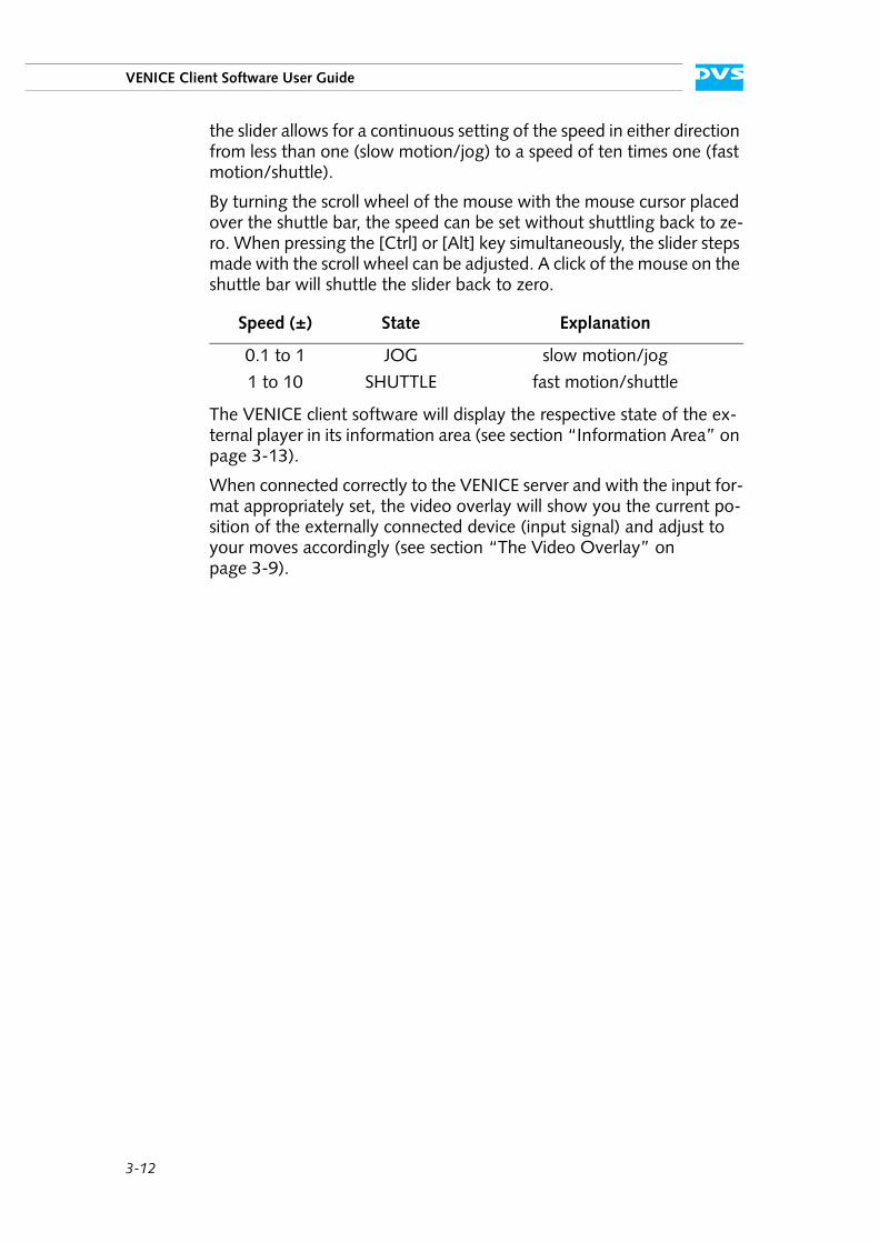
Speed (±) State Explanation
0.1 to 1 JOG slow motion/jog
1 to 10 SHUTTLE fast motion/shuttle
3-13
Playing Out Clips
3
2
1
4
5
I
A
6
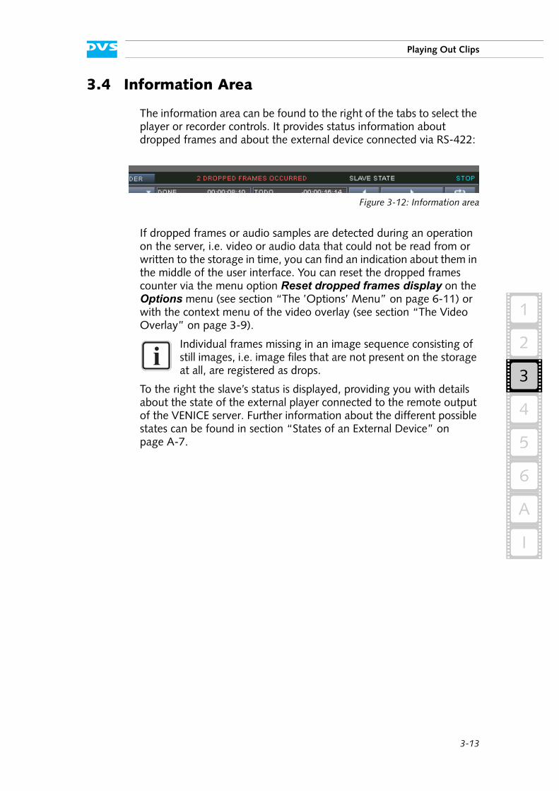
3.4 Information Area
The information area can be found to the right of the tabs to select the player or recorder controls. It provides status information about dropped frames and about the external device connected via RS-422:
Figure 3-12: Information area
If dropped frames or audio samples are detected during an operation on the server, i.e. video or audio data that could not be read from or written to the storage in time, you can find an indication about them in the middle of the user interface. You can reset the dropped frames counter via the menu option Reset dropped frames display on the Options menu (see section “The ’Options’ Menu” on page 6-11) or with the context menu of the video overlay (see section “The Video Overlay” on page 3-9).
To the right the slave’s status is displayed, providing you with details about the state of the external player connected to the remote output of the VENICE server. Further information about the different possible states can be found in section “States of an External Device” on page A-7.
Individual frames missing in an image sequence consisting of still images, i.e. image files that are not present on the storage at all, are registered as drops.
3-14
VENICE Client Software User Guide
3.5 Controlling the Devices (Player / Recorder)
In the playout mode the VENICE server assumes the role of the player while the external device is used as a recorder (see also section “Select-ing the Operation Mode” on page 2-5). Via the tabs at the top of the player/recorder controls you can switch between the controls of the VENICE server and the controls of the recorder (see section “Perform-ing the Operation” on page 2-7).
This section describes the controls available for the devices in detail. First the player controls are explained (tab VENICE) and after that the recorder controls (tab RECORDER).
3.5.1 Player Controls (VENICE)
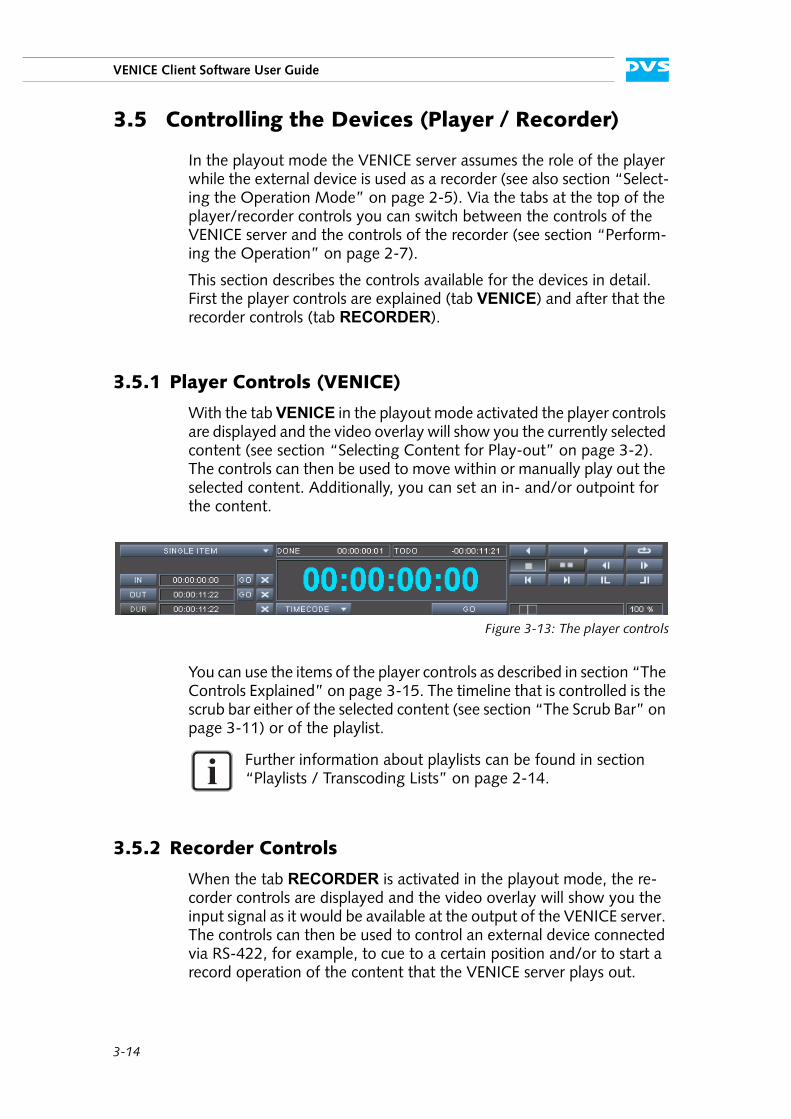
With the tab VENICE in the playout mode activated the player controls are displayed and the video overlay will show you the currently selected content (see section “Selecting Content for Play-out” on page 3-2). The controls can then be used to move within or manually play out the selected content. Additionally, you can set an in- and/or outpoint for the content.
Figure 3-13: The player controls
You can use the items of the player controls as described in section “The Controls Explained” on page 3-15. The timeline that is controlled is the scrub bar either of the selected content (see section “The Scrub Bar” on page 3-11) or of the playlist.
3.5.2 Recorder Controls
When the tab RECORDER is activated in the playout mode, the re-corder controls are displayed and the video overlay will show you the input signal as it would be available at the output of the VENICE server. The controls can then be used to control an external device connected via RS-422, for example, to cue to a certain position and/or to start a record operation of the content that the VENICE server plays out.
Further information about playlists can be found in section “Playlists / Transcoding Lists” on page 2-14.
3-15
Playing Out Clips
3
2
1
4
5
I
A
6
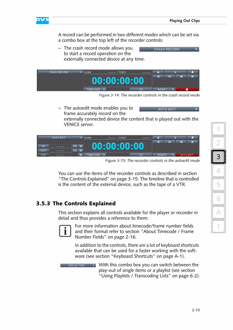
A record can be performed in two different modes which can be set via a combo box at the top left of the recorder controls:
– The crash record mode allows you to start a record operation on the externally connected device at any time.
Figure 3-14: The recorder controls in the crash record mode
– The autoedit mode enables you to frame accurately record on the externally connected device the content that is played out with the VENICE server.
Figure 3-15: The recorder controls in the autoedit mode
You can use the items of the recorder controls as described in section “The Controls Explained” on page 3-15. The timeline that is controlled is the content of the external device, such as the tape of a VTR.
3.5.3 The Controls Explained
This section explains all controls available for the player or recorder in detail and thus provides a reference to them:
For more information about timecode/frame number fields and their format refer to section “About Timecode / Frame Number Fields” on page 2-16.
In addition to the controls, there are a lot of keyboard shortcuts available that can be used for a faster working with the soft-ware (see section “Keyboard Shortcuts” on page A-1).
With this combo box you can switch between the play-out of single items or a playlist (see section “Using Playlists / Transcoding Lists” on page 6-2).
3-16
VENICE Client Software User Guide
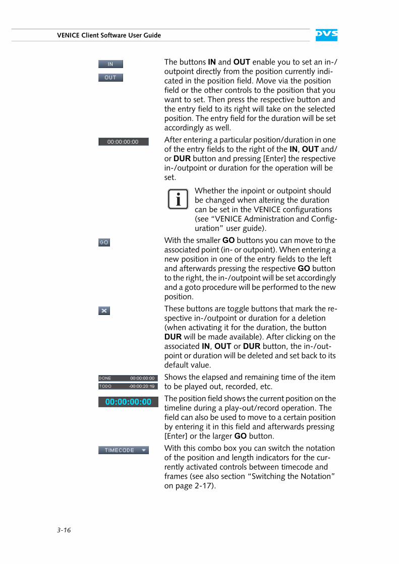
The buttons IN and OUT enable you to set an in-/outpoint directly from the position currently indi-cated in the position field. Move via the position field or the other controls to the position that you want to set. Then press the respective button and the entry field to its right will take on the selected position. The entry field for the duration will be set accordingly as well.
After entering a particular position/duration in one of the entry fields to the right of the IN, OUT and/or DUR button and pressing [Enter] the respective in-/outpoint or duration for the operation will be set.
Whether the inpoint or outpoint should be changed when altering the duration can be set in the VENICE configurations (see “VENICE Administration and Config-uration” user guide).
With the smaller GO buttons you can move to the associated point (in- or outpoint). When entering a new position in one of the entry fields to the left and afterwards pressing the respective GO button to the right, the in-/outpoint will be set accordingly and a goto procedure will be performed to the new position.
These buttons are toggle buttons that mark the re-spective in-/outpoint or duration for a deletion (when activating it for the duration, the button DUR will be made available). After clicking on the associated IN, OUT or DUR button, the in-/out-point or duration will be deleted and set back to its default value.
Shows the elapsed and remaining time of the item to be played out, recorded, etc.
The position field shows the current position on the timeline during a play-out/record operation. The field can also be used to move to a certain position by entering it in this field and afterwards pressing [Enter] or the larger GO button.
With this combo box you can switch the notation of the position and length indicators for the cur-rently activated controls between timecode and frames (see also section “Switching the Notation” on page 2-17).
3-17
Playing Out Clips
3
2
1
4
5
I
A
6
After entering a new position in the position field you can confirm your entry and start a goto proce-dure by pressing this button.
If available, you can play-out the timeline back-wards with this button, i.e. it will start a reverse play-out. Once activated, the button changes its appearance to its active state. To stop the reverse play-out you may click it again.
This button switches on the back-to-back mode for playlists. When activated, instead of playing out the complete playlist, only the item where the play-out is started (scrub bar cursor) will be played out.
If available, you can eject the tape of the externally connected device with this button.
With this button you can play out the contents of the timeline in real time. After activation the but-ton changes its appearance to its active state and you may press it again to stop the play-out.
With this button activated a play-out of the time-line will be performed endlessly in a loop: Once the the outpoint of the timeline is reached, the play-out will start from the inpoint again. To switch off the loop mode deactivate this button.
VENICE controls: This button activates the frames display mode, i.e. the frames of a video clip are shown when stepping backward or forward in the timeline.
External device controls: This button stops the cur-rent operation of the externally connected device.
If available, this button activates the fields display mode, i.e. the fields of a video clip are shown when stepping backward or forward in the timeline.
With these buttons you can step one video field/frame for- or backward in the timeline. The posi-tion field will indicate this accordingly.
You can jump to particular points on the timeline (e.g. timeline begin, inpoint, outpoint, or timeline end) with these buttons. The first button jumps to the point that is previously located on the timeline while the second button jumps to the next one.
You can jump to the timeline begin or timeline end with these buttons. The first button jumps to the very first frame of the timeline while the second button jumps to the very last one.
3-18
VENICE Client Software User Guide
These buttons initiate a fast backward or forward operation of the external player. After activation the buttons will change their appearance to the ac-tive state and you may press the respective button again to stop the operation.
Determines the speed of the played out material. Either enter a speed in percent in the entry field to the right or use the slider to set it.
With the Insert/Assemble combo box you deter-mine whether data (e.g. on VTRs) should be insert-ed or overwritten. While the assemble mode usually overwrites all data (video, audio and time-code) on the tape of the external device, in the in-sert mode you can select via the Output select settings the data that should be sent to the exter-nal device (see section “Selecting Essences for Play-out” on page 3-6).
Once your record is set up correctly you can start a record operation with these buttons. Then the re-spective button changes its appearance to its active state and the capturing begins: In the crash record mode it starts immediately, and in the autoedit mode it accounts for preroll, postroll, etc. In case it is necessary to terminate the record, you have to click the button again.
3-19
Playing Out Clips
3
2
1
4
5
I
A
6
3.6 Playing Out with the VENICE Server
With the DVS software in the playout mode you can play out the currently selected content:
– You can play out content manually.– You can perform a crash record on an externally connected device.– You can perform an automated play-out of the content while at the
same time frame accurately recording it on the externally connected device (autoedit record).
– You can set the playout mode into slave mode to control the play-out from an externally connected device.
All these procedures are explained in this section.
3.6.1 How to Play Out Clips Manually
To play out clips in the playout mode perform the steps as described be-low:
Select the video and audio content that should be played out with the Source items as described in section “Selecting Content for Play-out” on page 3-2.
If necessary, specify the essences for the play-out with the Output select items (see section “Selecting Essences for Play-out” on page 3-6).
If necessary, configure the output format to your requirements with the Output settings items (see section “Configuring the Output Settings” on page 3-7).
If not already activated, switch to the player controls by selecting the tab VENICE (see section “Controlling the Devices (Player / Recorder)” on page 3-14).
When controlling the video channel from a client, the images in the video overlay are transmitted via network. There may be a time delay until the material is displayed in the video overlay and it may seem as if drops occurred. Real drops on the server, however, will be automatically detected and you will be in-formed about them in the information area (see section “Infor-mation Area” on page 3-13).
Via project files or presets the software can be preconfigured for certain tasks. Then it may not be necessary to perform all the configurations described below (see section “Preconfigur-ing the VENICE Client Software” on page 2-13).
3-20
VENICE Client Software User Guide
As soon as the player controls are activated and video content is select-ed for a play-out, the video overlay will show you the selected content.
If wanted, set an in-/outpoint or duration for the content to be played out (see section “Player Controls (VENICE)” on page 3-14).
Afterwards press the play button ( ) of the player controls.
The VENICE server then performs the play-out: The video content will be displayed in the configured video format and in real time in the video overlay and video as well as audio will be given out at the outputs of the VENICE server.
3.6.2 How to Crash Record with the External Device
In the playout mode you can perform a crash record on the externally connected device. It will then immediately record the signal that is present at its input, e.g. the content that is played out manually with the VENICE server.
To initiate a crash record perform the steps as described below:
If not already activated, switch to the recorder controls by selecting the tab RECORDER (see section “Controlling the Devices (Player / Recorder)” on page 3-14).
Make sure that the crash record mode is selected (see section “Recorder Controls” on page 3-14).
If appropriate, use the recorder controls and the video overlay to move to the correct position on the external device for the data to be recorded.
If wanted, type in the duration that the record should last in the DUR field.
Afterwards press the record button ( ) of the record controls.
The external device will then start the record and as an indication for this the characters of the position field turn red. The video overlay will show you what is present at the server’s input. Once the recorded clip corresponds to the set duration in the field DUR, the record operation
For this procedure the external device has to be connected cor-rectly to the VENICE server (video, audio, timecode, and RS-422). Additionally, the device has to be set to accept re-mote control.
A crash record can be started without further ado, meaning, if not required, you do not have to set anything. However, you can record the signal given out by the VENICE server (see sec-tion “How to Play Out Clips Manually” on page 3-19).
3-21
Playing Out Clips
3
2
1
4
5
I
A
6
will be stopped automatically. If no duration is set, you can terminate the record manually whenever you want by clicking the record button once again.
3.6.3 How to Autoedit Record with the External Device
In the autoedit record mode you can control a play-out by the VENICE server while at the same time recording it frame accurately with the ex-ternal device. The following describes what to do to perform an auto-edit record.
Setting up the Playout Mode
To perform an autoedit record in the playout mode you first have to configure what and how to play out with the VENICE server:
Select the video and audio content that should be played out with the Source items as described in section “Selecting Content for Play-out” on page 3-2.
If necessary, specify the essences for the play-out with the Output select items (see section “Selecting Essences for Play-out” on page 3-6).
If necessary, configure the output format to your requirements with the Output settings items (see section “Configuring the Output Settings” on page 3-7).
If not already activated, switch to the player controls by selecting the tab VENICE (see section “Controlling the Devices (Player / Recorder)” on page 3-14).
As soon as the player controls are activated and video content is select-ed for a play-out, the video overlay will show you the selected content.
Set an in- and outpoint for the content to be played out (see section “Player Controls (VENICE)” on page 3-14).
After this you have successfully set up the VENICE server for a play-out and you now have to configure the external device for the record.
For this procedure the external device has to be connected cor-rectly to the VENICE server (video, audio, timecode, and RS-422). Additionally, the device has to be set to accept re-mote control.
Via project files or presets the software can be preconfigured for certain tasks. Then it may not be necessary to perform all the configurations described below (see section “Preconfigur-ing the VENICE Client Software” on page 2-13).
3-22
VENICE Client Software User Guide
Configuring the External Device for the Record
To record the output of the VENICE server with the external device the device has to be set up properly:
If not already activated, switch to the recorder controls by selecting the tab RECORDER (see section “Controlling the Devices (Player / Recorder)” on page 3-14).
Make sure that the autoedit record mode is selected (see section “Recorder Controls” on page 3-14).
Use the recorder controls and the video overlay to search for the exact inpoint in the material of the externally connected device.
Press the IN button to set the inpoint to the selected position. Alter-natively, you may enter the respective position manually in the entry field of the inpoint afterwards pressing [Enter].
After that use the controls to move to the desired outpoint in the material.
Click on the button OUT or enter the position in the respective entry field to the right of the OUT button and afterwards press [Enter].
With this the selected in- and outpoint will be shown in the associated entry fields of the record controls and the duration will be set accord-ingly.
As the next step you have to start the record.
Starting the Record
When everything is set up properly, you can start the autoedit record at any time:
To start the autoedit record press the button AUTO EDIT of the record controls ( ).
The VENICE server will then initiate the record on the external device: The external device will go to its preroll position and start playing from there. As soon as the specified inpoint is reached the play-out of the server starts and the external device performs the record up to the set outpoint/duration (characters in the position field turn red). After this the play-out operation of the VENICE server stops automatically. Once the external device stops its operation (postroll), the video material has been recorded successfully on the external device.
Alternatively, you may also specify just one of the entries for in- or outpoint and afterwards set the duration of the record.
To terminate the autoedit record manually you have to click the record button once again.
3-23
Playing Out Clips
3
2
1
4
5
I
A
6
3.6.4 How to Perform a Play-out in Slave Mode
In the playout mode you can control the VENICE server by remote and send a play command via RS-422. After receiving the command the server will play out the currently selected content according to the set-tings specified with the operation mode configurations.
To prepare the VENICE server for a slave mode play-out perform the following:
Select the video and audio content that should be played out with the Source items as described in section “Selecting Content for Play-out” on page 3-2.
If necessary, specify the essences for the play-out with the Output select items (see section “Selecting Essences for Play-out” on page 3-6).
If necessary, configure the output format to your requirements with the Output settings items (see section “Configuring the Output Settings” on page 3-7).
Then activate the button SLAVE (see section “Slave Mode” on page 2-9).
The slave mode control window appears on the screen.
If necessary, specify further details about the play-out there, such as an in- or outpoint. For further details about this window see section “Slave Mode” on page 2-9.
After this the VENICE server waits for a play-out command via RS-422 to begin the play-out.
To stop the slave mode play-out perform the following:
Either send the respective command via RS-422 or terminate the slave mode by clicking on the CLOSE button of the slave mode control window.
The VENICE server then stops the slave mode play-out of the selected content.
Via project files or presets the software can be preconfigured for certain tasks. Then it may not be necessary to perform all the configurations described below (see section “Preconfigur-ing the VENICE Client Software” on page 2-13).

3-24
VENICE Client Software User Guide
4-1
4
4
2
1
3
5
I
A
6
Recording Clips
With a connection to a video channel of the VENICE server established (see section “Connecting to the VENICE Server” on page 2-4) you can use this channel for record operations. For this the VENICE client software must be in the INGEST MODE (see section “Selecting the Operation Mode” on page 2-5).
Figure 4-1: Settings, controls and configurations of the ingest mode
In the ingest mode you have the following possibilities at hand:
– You can configure all input related settings.– You can control an externally connected device, for example, to
verify a position and set in- and/or outpoint.– You can control the externally connected device for a play-out
operation while simultaneously recording with the VENICE server.– You can set the VENICE server in slave mode for a remote con-
trolled record.
This chapter describes how to record clips on the VENICE server with the VENICE client software.
Because most items described in this chapter are identical and can be used in the same way as in the playout mode, the fol-lowing sections will often just reference to the items in chapter “Playing Out Clips” on page 3-1. However, the important dif-ferences will be mentioned.
4-2
VENICE Client Software User Guide
4.1 Configuring a Record
Before a record can be performed with the connected video channel of the VENICE server you have to set up the record and the input related settings (see also section “Configuring the Operation Mode” on page 2-6). As a minimum you have to determine the location of the record. This section describes the necessary settings that have to be made before capturing with the VENICE server.
4.1.1 Configuring the Input Settings
To record video and audio with the VENICE server, you have to config-ure the input format appropriately. By clicking on the triangle button to the left of the item Input settings, the necessary settings can be ex-panded (or collapsed):
Figure 4-2: The input format settings items
With the settings items of the Input settings configure the input video format so that it matches the incoming video signal. You may also use the AUTODETECT button to let the VENICE server detect the video for-mat of the input signal automatically. Once set, the respective format will be automatically applied to the appropriate input port(s) of the VENICE server. Because, if not configured otherwise, the output format is by default linked to the input format, it will be set to the same raster and the video overlay of the VENICE client software will reflect this ac-cordingly. Afterwards some of the file formats for a capturing may not be available anymore due to the selected video raster or color space.
Via project files or presets the software can be preconfigured for certain tasks. Then it may not be necessary to perform all the configurations described below (see section “Preconfigur-ing the VENICE Client Software” on page 2-13).
Between the operation modes of the VENICE server (see sec-tion “Selecting the Operation Mode” on page 2-5) different video format settings can be set. Further information about this as well as about the relation of the input settings to the output settings can be found in section “Configuring the Output Set-tings” on page 3-7.
4-3
4
Recording Clips
2
1
3
5
I
A
6
Furthermore, with the Input settings you can determine the audio in-put and timecode settings for the record.
4.1.2 Selecting Essences for Record
With the Input select settings of the ingest mode you have to select the essences (type of material) that you want to capture. You can choose whether you want to record audio or video alone, or both to-gether. By clicking on the triangle button to the left of the item Input select, the necessary settings can be expanded (or collapsed):
Figure 4-3: The input select items
When the settings items are collapsed, the currently selected essences will be shown in abbreviated form to the right of the Input select con-figurations: T for timecode, V for video and A<x> for the selected audio channels.
As soon as a video input signal is detected that corresponds to the set input video format (see section “Configuring the Input Settings” on page 4-2), the matching essences in the user interface will be activated automatically.
With the Input select settings choose the essences according to your needs. By activating or deactivating one of the provided buttons you can determine the essence that you want to capture. For example, if you want to capture video, the button VIDEO must be activated.
The audio channel buttons above the audio peakmeter represent the 16 audio channels that are provided by the VENICE server. If, for ex-ample, channels 1 and 2 are selected (as in the figure above), the audio signals that are available at these channels of the VENICE server will be captured.
The input video format has to match the incoming signal, i.e. it must be of the same format and raster as the incoming signal.
Further information about audio and the way it is handled in the DVS software can be found in section “About Audio” on page 2-18.
Currently the button TIMECODE provides no functionality.
4-4
VENICE Client Software User Guide
4.1.3 Configuring the Output Settings (File Settings)
With the Output settings items you determine the file format(s) of the file(s) to be recorded. By clicking on the triangle button to the left, the necessary settings can be expanded (or collapsed):
Figure 4-4: The file format settings
They are divided into different items for audio and video.
Video File Settings
Select from the File format combo box the file format for your video data to be recorded. Various file formats are supported and lists of them can be found in section “Supported File Formats” on page A-3.
Depending on the selected file format additional codec or file types will be available (to determine bit depth and/or byte order settings). If pro-vided by the file format, select from the File type combo box the de-sired additional codec or file type.
In case a compressed file format has been selected, you can select the type of compression that should be applied to the recorded material with the combo box Codec.
Once a file type/codec has been selected, you have to choose the way a color space conversion and scaling has to be done with the combo box Color range. It specifies whether the color space range of the re-corded clip will be in a restricted (head) or in a full value range (full).
These settings are connected to the input settings and record essences. Some of the file formats may not be available due to the selected input video format and/or activated essence.
4-5
4
Recording Clips
2
1
3
5
I
A
6
Audio File Settings
Select from the File format combo box the file format for your audio data to be recorded. Various file formats are supported and a list of them can be found in section “Supported File Formats” on page A-3.
From the Bit depth combo box select the bit depth of the audio files. The DVS software supports all common resolutions (bit depths).
The combo boxes File type and Sampling are available for informa-tion purposes and provide no functionality.
4.1.4 Selecting the Storage Location and File Name
Before performing a record you have to determine the name of the cap-tured file(s) and where to save them. By clicking on the triangle button to the left of the item Destination, the necessary settings can be ex-panded (or collapsed):
Figure 4-5: The file name and path settings
The file name has to be entered manually, but there are several ways to set a record path:
1. You can enter the respective path manually.2. You can select a path via a dialog window.3. You can drag and drop a path from one of the browsing panes of
Spycer.
All these procedures will be explained in this section.
Once a path has been selected, the Disk capacity item shows you graphically the amount of disk space that is currently used on the en-tered storage (bar and percentage value). The timecode values of the used and free disk space will adapt depending on the currently config-ured input settings (video raster).
Normally, when a container format is selected as the file format (e.g. MXF), you cannot generate audio and video separately. Both will automatically be included in the created file.
Further information about audio and the way it is handled in the DVS software can be found in section “About Audio” on page 2-18.
4-6
VENICE Client Software User Guide
Entering a Path and File Name Manually
You can enter the path and file name for a record manually with the en-try fields of the Destination settings. Just start to enter something in the entry fields and another dialog window will be opened where you can type in the respective path or file name:
Figure 4-6: Entering a path or file name
In this window enter the path or file name for the record on the VENICE server and confirm your entry with the OK button. Perform this for the path and the file name separately with the available entry fields.
When entering a path together with a directory that does not exist, it will be created when clicking the OK button.
When entering a file name for the record, you just have to enter the prefix without any numbering or file extension. These will be provided by the software automatically. If a file name is not specified, the default name NewClip will be given to the recorded clip.
The software arranges the clips numerically, meaning the recorded clips will carry a consecutive number
which will be added to the file name in a certain way (see section “The Captured Files” on page 4-7). To the right of the field File name is a field that shows you the number that will be used for the next record. As a standard for every new file name the numbering starts with 000/--- meaning that no numbering will be added (the number will be added though when more clips with the same name are recorded). Af-ter a record operation the consecutive number is automatically in-creased by one which ensures that a once captured clip will not be overwritten if the file name remains unaltered.
The entered path must lead to the storage of the VENICE serv-er to which you are currently connected.
4-7
4
Recording Clips
2
1
3
5
I
A
6
Selecting a Path Via a Dialog Window
For the selection of a record path you can use the button to the right of the entry field Path of the Destination settings ( ). It will open a dialog window similar to a browsing pane in Spycer.
Browse in the directory tree of this window to the directory where the recorded files should be stored. You may also create a new directory via the provided buttons of this window.
Once a directory has been selected, confirm it with the OK button. Af-terwards the path will be displayed in the respective entry field of the Destination settings.
Selecting a Path Via Spycer
You can drag and drop the path for a record directly from a browsing pane of Spycer to the user interface of the VENICE client software.
In one of the available browsing panes select from a network/system combo box the VENICE server to which you are currently connected and browse in the directory tree to the directory where the recorded files should be stored. Then take this directory and drag and drop it any-where on the user interface of the VENICE client software.
Afterwards the path will be displayed in the respective entry field of the Destination settings.
4.1.5 The Captured Files
The video and audio data captured during a record will be stored at the location set with the Destination settings items (see section “Selecting the Storage Location and File Name” on page 4-5).
For the generated items one metaclip will be created (see section “Metaclips” on page 2-15) directly at the selected location.
This window is generated by Spycer. Without a Spycer applica-tion installed it will not be available.
For any further information about this window see section “Se-lecting Content Via a Dialog Window” on page 3-3 as well as the “Spycer” user guide.
For any further information about this see section “Selecting Content Via Spycer” on page 3-4.
The directory must be located on the storage of the VENICE server to which you are currently connected.
Further explanations of Spycer and its usage can be found in the “Spycer” user guide.
4-8
VENICE Client Software User Guide
The names for the created items will take the field File name of the Destination settings items as the prefix. Behind this, in case of further records with the same file name, the consecutive number will be added.
When recording with VENICE this would lead to the following generat-ed items:
Container Formats
Most container files will be stored at the selected location directly. How-ever, if several files are generated they may get sorted into a subfolder with the name <prefix><consecutiveNo>. If a P2 format has been selected, the P2 data structure will be observed.
With container file formats audio and video are normally recorded both in the same file. If audio has been created in separate files (see also sec-tion “Supported File Formats” on page A-3), they will carry the follow-ing names:
Still Image Formats
The file names of still image formats will be followed by an underscore and an increasing 7-digit number for the individual image files (file/frame number):
If audio has been recorded as well, the audio files will provide the same file name but without the frame numbering:
Metaclip: <prefix><consecutiveNo>.vamc
Data subfolder: –
Container file: <prefix><consecutiveNo>.<ext>
Audio files: <prefix><consecutiveNo>A<chan-No>.<ext>
Metaclip: <prefix><consecutiveNo>.vamc
Data subfolder: <prefix><consecutiveNo>
Still image files: <prefix><consecutiveNo.>_<file/frame no.>.<ext>
Audio files: <prefix><consecutive no.>.<ext>
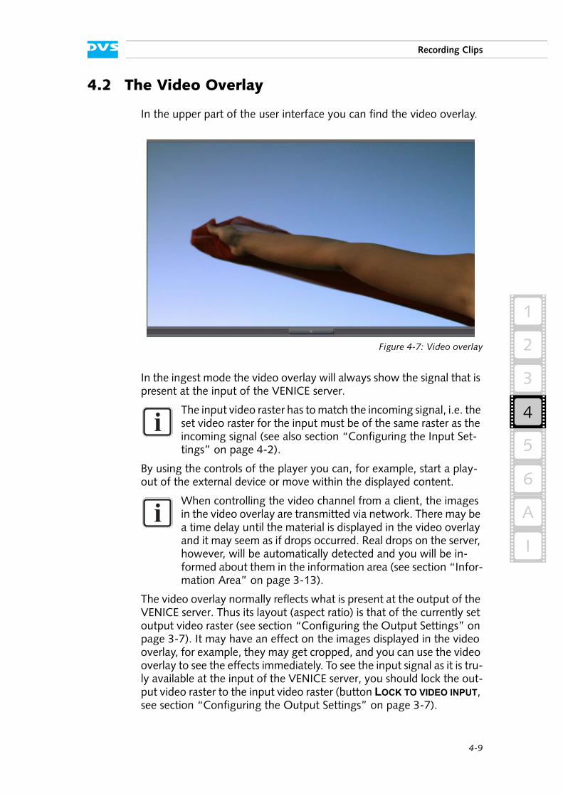
4-9
4
Recording Clips
2
1
3
5
I
A
6
4.2 The Video Overlay
In the upper part of the user interface you can find the video overlay.
Figure 4-7: Video overlay
In the ingest mode the video overlay will always show the signal that is present at the input of the VENICE server.
By using the controls of the player you can, for example, start a play-out of the external device or move within the displayed content.
The video overlay normally reflects what is present at the output of the VENICE server. Thus its layout (aspect ratio) is that of the currently set output video raster (see section “Configuring the Output Settings” on page 3-7). It may have an effect on the images displayed in the video overlay, for example, they may get cropped, and you can use the video overlay to see the effects immediately. To see the input signal as it is tru-ly available at the input of the VENICE server, you should lock the out-put video raster to the input video raster (button LOCK TO VIDEO INPUT, see section “Configuring the Output Settings” on page 3-7).
The input video raster has to match the incoming signal, i.e. the set video raster for the input must be of the same raster as the incoming signal (see also section “Configuring the Input Set-tings” on page 4-2).
When controlling the video channel from a client, the images in the video overlay are transmitted via network. There may be a time delay until the material is displayed in the video overlay and it may seem as if drops occurred. Real drops on the server, however, will be automatically detected and you will be in-formed about them in the information area (see section “Infor-mation Area” on page 3-13).
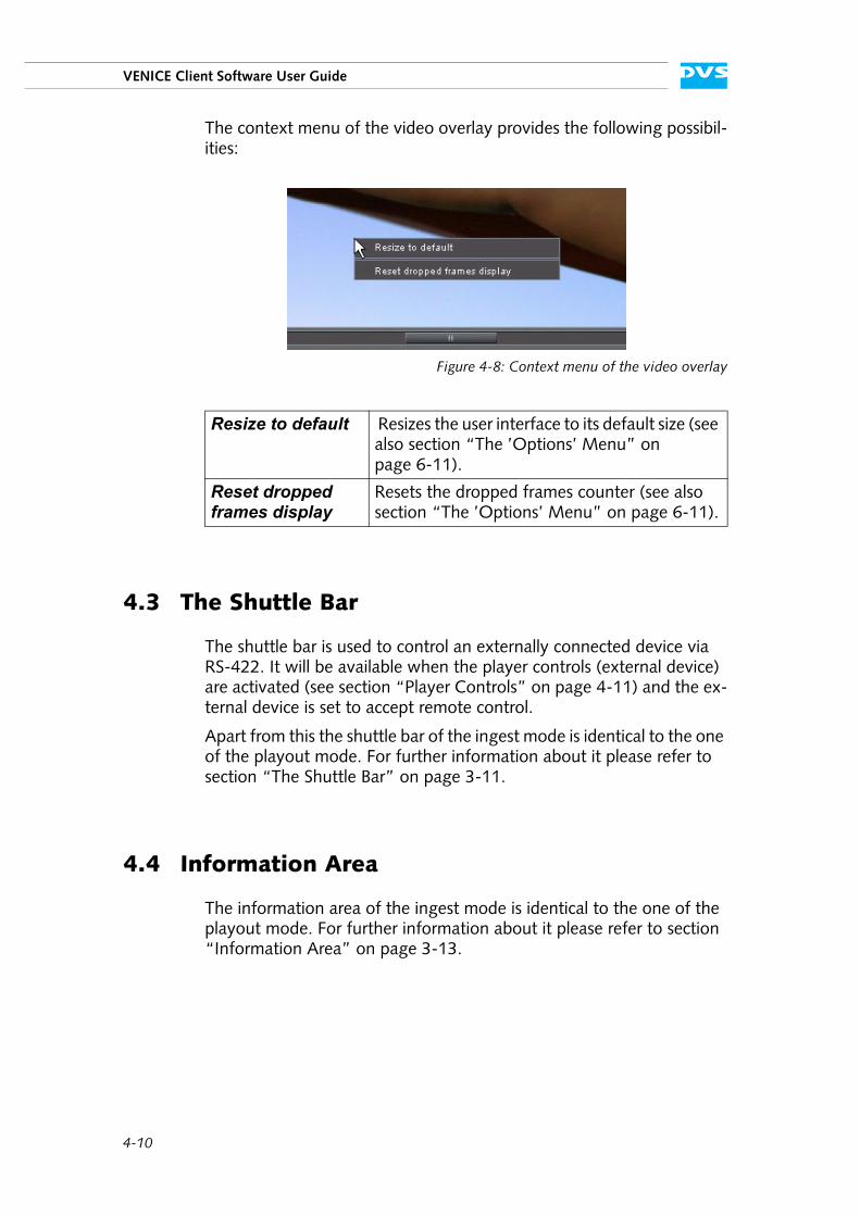
4-10
VENICE Client Software User Guide
The context menu of the video overlay provides the following possibil-ities:
Figure 4-8: Context menu of the video overlay
4.3 The Shuttle Bar
The shuttle bar is used to control an externally connected device via RS-422. It will be available when the player controls (external device) are activated (see section “Player Controls” on page 4-11) and the ex-ternal device is set to accept remote control.
Apart from this the shuttle bar of the ingest mode is identical to the one of the playout mode. For further information about it please refer to section “The Shuttle Bar” on page 3-11.
4.4 Information Area
The information area of the ingest mode is identical to the one of the playout mode. For further information about it please refer to section “Information Area” on page 3-13.
Resize to default Resizes the user interface to its default size (see also section “The ’Options’ Menu” on page 6-11).
Reset dropped frames display
Resets the dropped frames counter (see also section “The ’Options’ Menu” on page 6-11).
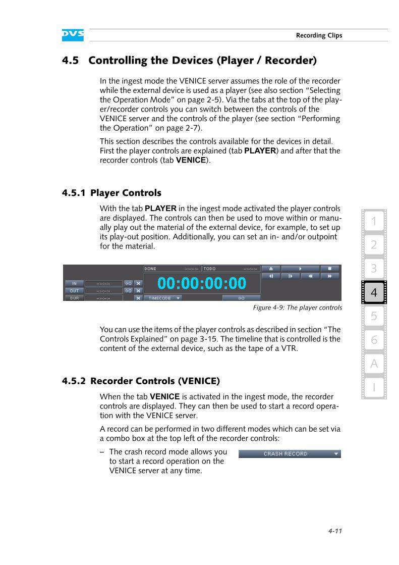
4-11
4
Recording Clips
2
1
3
5
I
A
6
4.5 Controlling the Devices (Player / Recorder)
In the ingest mode the VENICE server assumes the role of the recorder while the external device is used as a player (see also section “Selecting the Operation Mode” on page 2-5). Via the tabs at the top of the play-er/recorder controls you can switch between the controls of the VENICE server and the controls of the player (see section “Performing the Operation” on page 2-7).
This section describes the controls available for the devices in detail. First the player controls are explained (tab PLAYER) and after that the recorder controls (tab VENICE).
4.5.1 Player Controls
With the tab PLAYER in the ingest mode activated the player controls are displayed. The controls can then be used to move within or manu-ally play out the material of the external device, for example, to set up its play-out position. Additionally, you can set an in- and/or outpoint for the material.
Figure 4-9: The player controls
You can use the items of the player controls as described in section “The Controls Explained” on page 3-15. The timeline that is controlled is the content of the external device, such as the tape of a VTR.
4.5.2 Recorder Controls (VENICE)
When the tab VENICE is activated in the ingest mode, the recorder controls are displayed. They can then be used to start a record opera-tion with the VENICE server.
A record can be performed in two different modes which can be set via a combo box at the top left of the recorder controls:
– The crash record mode allows you to start a record operation on the VENICE server at any time.
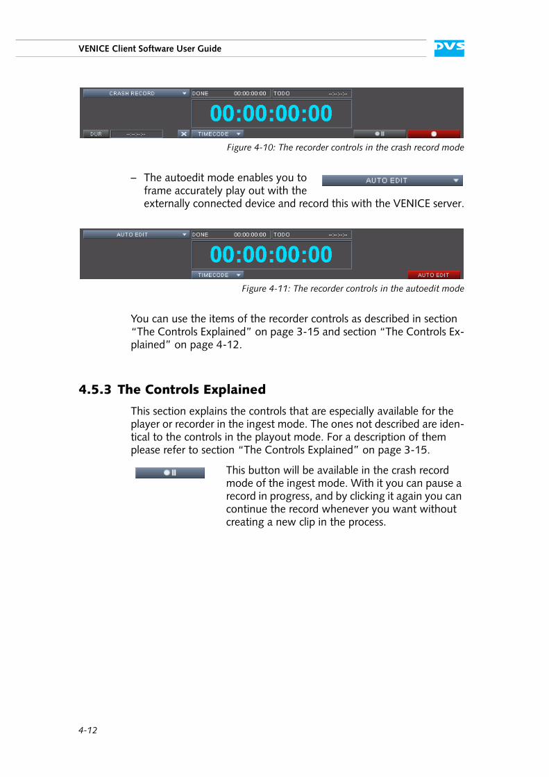
4-12
VENICE Client Software User Guide
Figure 4-10: The recorder controls in the crash record mode
– The autoedit mode enables you to frame accurately play out with the externally connected device and record this with the VENICE server.
Figure 4-11: The recorder controls in the autoedit mode
You can use the items of the recorder controls as described in section “The Controls Explained” on page 3-15 and section “The Controls Ex-plained” on page 4-12.
4.5.3 The Controls Explained
This section explains the controls that are especially available for the player or recorder in the ingest mode. The ones not described are iden-tical to the controls in the playout mode. For a description of them please refer to section “The Controls Explained” on page 3-15.
This button will be available in the crash record mode of the ingest mode. With it you can pause a record in progress, and by clicking it again you can continue the record whenever you want without creating a new clip in the process.
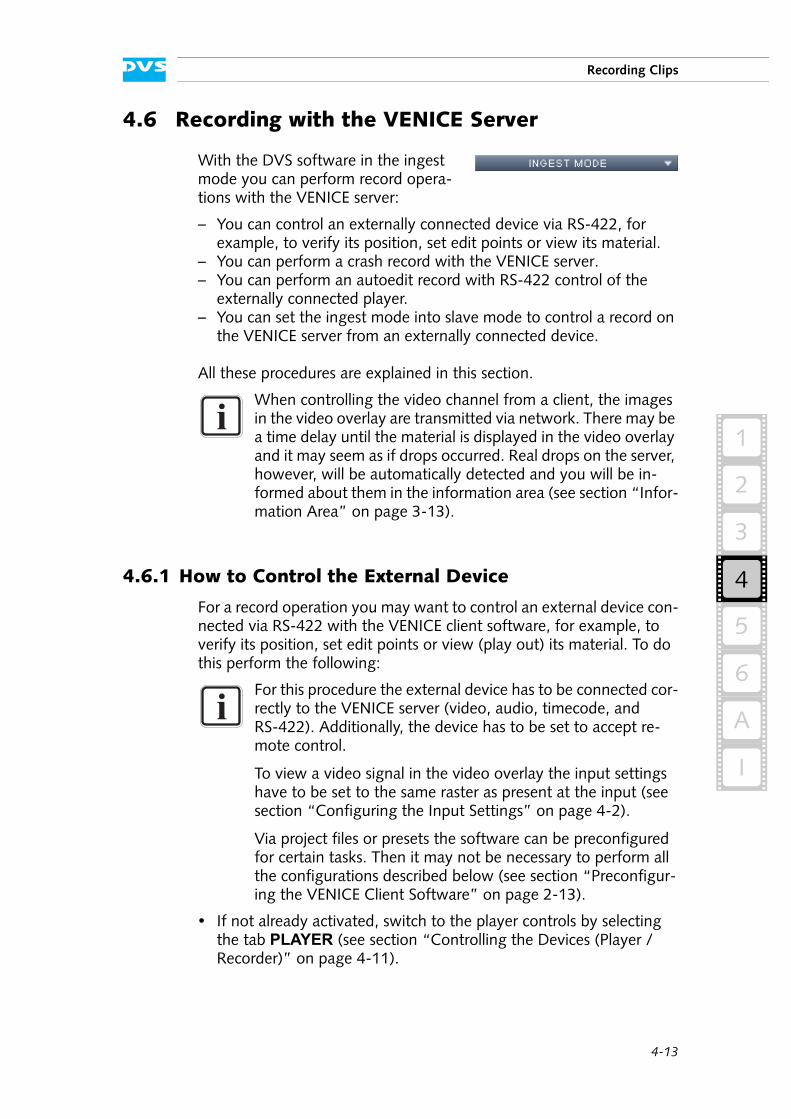
4-13
4
Recording Clips
2
1
3
5
I
A
6
4.6 Recording with the VENICE Server
With the DVS software in the ingest mode you can perform record opera-tions with the VENICE server:
– You can control an externally connected device via RS-422, for example, to verify its position, set edit points or view its material.
– You can perform a crash record with the VENICE server.– You can perform an autoedit record with RS-422 control of the
externally connected player.– You can set the ingest mode into slave mode to control a record on
the VENICE server from an externally connected device.
All these procedures are explained in this section.
4.6.1 How to Control the External Device
For a record operation you may want to control an external device con-nected via RS-422 with the VENICE client software, for example, to verify its position, set edit points or view (play out) its material. To do this perform the following:
If not already activated, switch to the player controls by selecting the tab PLAYER (see section “Controlling the Devices (Player / Recorder)” on page 4-11).
When controlling the video channel from a client, the images in the video overlay are transmitted via network. There may be a time delay until the material is displayed in the video overlay and it may seem as if drops occurred. Real drops on the server, however, will be automatically detected and you will be in-formed about them in the information area (see section “Infor-mation Area” on page 3-13).
For this procedure the external device has to be connected cor-rectly to the VENICE server (video, audio, timecode, and RS-422). Additionally, the device has to be set to accept re-mote control.
To view a video signal in the video overlay the input settings have to be set to the same raster as present at the input (see section “Configuring the Input Settings” on page 4-2).
Via project files or presets the software can be preconfigured for certain tasks. Then it may not be necessary to perform all the configurations described below (see section “Preconfigur-ing the VENICE Client Software” on page 2-13).
4-14
VENICE Client Software User Guide
Use the player controls and the video overlay to search for a certain position or to play out the material of the externally connected device.
With this the external device can be controlled and you can, for exam-ple, verify the material. However, for an autoedit record with the VENICE server an in- and outpoint should be set as well, which will be explained next:
Use the player controls and the video overlay to search for the exact position for the inpoint in the material of the externally connected device.
Once the external device shows the correct position, press the IN button to set the inpoint to this position. Alternatively, you can enter the respective position manually in the entry field of the inpoint afterwards pressing [Enter].
After that use the controls to move to the desired outpoint in the material.
Click on the button OUT or enter the position in the respective entry field to the right of the OUT button and afterwards press [Enter].
With this the selected in- and outpoint will be shown in the associated entry fields of the player controls and the duration will be set accord-ingly.
When this is finished you can, for example, start an autoedit record as described in section “How to Autoedit Record with the VENICE Server” on page 4-15.
4.6.2 How to Crash Record with the VENICE Server
In the ingest mode you can perform a crash record with the VENICE server. It will then immediately record, according to your settings, the signal that is present at its input, e.g. the content that is played out manually with an external device (see section “How to Control the Ex-ternal Device” on page 4-13).
To initiate a crash record perform the steps as described below:
If necessary, configure the input format so that it matches the signal present at the server’s input with the Input settings items (see sec-tion “Configuring the Input Settings” on page 4-2).
Determine a file name and path for the file(s) to be recorded with the Destination items as described in section “Selecting the Stor-age Location and File Name” on page 4-5.
Alternatively, you may also specify one of the entries for in- or outpoint and afterwards set the duration of the play-out.
4-15
4
Recording Clips
2
1
3
5
I
A
6
If necessary, specify the essences that you want to record with the Input select items (see section “Selecting Essences for Record” on page 4-3).
If necessary, set up the file format(s) of the file(s) to be recorded via the Output settings items (see section “Configuring the Output Settings (File Settings)” on page 4-4).
If not already activated, switch to the recorder controls by selecting the tab VENICE (see section “Controlling the Devices (Player / Recorder)” on page 4-11).
Make sure that the recorder controls are set to the crash record mode (see section “Recorder Controls (VENICE)” on page 4-11).
If wanted, type in the duration that the record should last in the DUR field.
Afterwards press the record button ( ) of the record controls.
The VENICE server will then start the record and as an indication for this the characters of the position field turn red. The video overlay will show you what is present at the server’s input, i.e. the content that is record-ed as it will be present at the output of the VENICE server (i.e. with the specified output video format). Once the captured clip corresponds to the set duration in the field DUR, the record operation will be stopped automatically. If no duration is set, you can terminate the record man-ually whenever you want by clicking the record button once again.
Once the record has finished, you can switch to the playout mode and review the recorded material immediately: The metaclip of the captured clip will be automatically set as the content to be played out (see section “Selecting Content for Play-out” on page 3-2).
4.6.3 How to Autoedit Record with the VENICE Server
In the ingest mode you can perform an autoedit record with the VENICE server while at the same time frame accurately controlling the
With the pause record button ( ) you can pause the record in progress, and by clicking it again you can contin-ue the record whenever you want without creating a new clip.
4-16
VENICE Client Software User Guide
play-out of the externally connected player. The following describes what to do to perform an autoedit record.
Setting up the Ingest Mode
To perform an autoedit record in the ingest mode you first have to con-figure where and how to record with the VENICE server:
If necessary, configure the input format so that it matches the signal present at the server’s input with the Input settings items (see sec-tion “Configuring the Input Settings” on page 4-2).
Determine a file name and path for the file(s) to be recorded with the Destination items as described in section “Selecting the Stor-age Location and File Name” on page 4-5.
If necessary, specify the essences that you want to record with the Input select items (see section “Selecting Essences for Record” on page 4-3).
If necessary, set up the file format(s) of the file(s) to be recorded via the Output settings items (see section “Configuring the Output Settings (File Settings)” on page 4-4).
After this you have successfully set up the VENICE server for a record operation and you now have to configure the external device for the play-out.
Setting up the External Device for the Play-out
To perform an autoedit record in the ingest mode you first have to set up the external device properly so that it will play out the correct ma-terial during the record operation:
Perform the steps described in section “How to Control the External Device” on page 4-13 and set an in- and outpoint for the play-out.
When this is done, you can start the record.
Starting the Record
When everything is set up properly, you can start the autoedit record at any time:
For this procedure the external device has to be connected cor-rectly to the VENICE server (video, audio, timecode, and RS-422). Additionally, the device has to be set to accept re-mote control.
Via project files or presets the software can be preconfigured for certain tasks. Then it may not be necessary to perform all the configurations described below (see section “Preconfigur-ing the VENICE Client Software” on page 2-13).
4-17
4
Recording Clips
2
1
3
5
I
A
6
If not already activated, switch to the recorder controls by selecting the tab VENICE (see section “Controlling the Devices (Player / Recorder)” on page 4-11).
Make sure that the recorder controls are set to the autoedit record mode (see section “Recorder Controls (VENICE)” on page 4-11).
To start the autoedit record press the button AUTO EDIT of the record controls ( ).
The VENICE server then performs the record in accordance with your settings: The external player will go to its preroll position and start play-ing from there. The video overlay will show you what is present at the server’s input, i.e. the content that is recorded as it will be present at the output of the VENICE server (i.e. with the specified output video for-mat). As soon as the inpoint on the external player is reached the record is performed by the VENICE server up to the point of the set outpoint/duration. During the record the characters of the position field turn red. Once the outpoint is reached, the record will be terminated automati-cally.
Once the record has finished, you can switch to the playout mode of the DVS software and review the recorded material immediately: The metaclip of the captured clip will be automatically set as the content to be played out (see section “Selecting Content for Play-out” on page 3-2).
4.6.4 How to Perform a Slave Mode Record
In the ingest mode you can control the VENICE server by remote and send a record command to it via RS-422. After receiving the command the VENICE server will record the incoming signal according to your set-tings and save the captured material accordingly.
To prepare the VENICE server for a slave mode recording perform the following:
The record controls will be unavailable when the input set-tings are not set to the same raster as present at the input and/or the external player is not set to accept remote con-trol.
To terminate the autoedit record manually you have to click the record button once again.
Via project files or presets the software can be preconfigured for certain tasks. Then it may not be necessary to perform all the configurations described below (see section “Preconfigur-ing the VENICE Client Software” on page 2-13).
4-18
VENICE Client Software User Guide
If necessary, configure the input format so that it matches the signal present at the server’s input with the Input settings items (see sec-tion “Configuring the Input Settings” on page 4-2).
Determine a file name and path for the file(s) to be recorded with the Destination items as described in section “Selecting the Stor-age Location and File Name” on page 4-5.
If necessary, specify the essences that you want to record with the Input select items (see section “Selecting Essences for Record” on page 4-3).
If necessary, set up the file format(s) of the file(s) to be recorded via the Output settings items (see section “Configuring the Output Settings (File Settings)” on page 4-4).
Then activate the button SLAVE (see section “Slave Mode” on page 2-9).
The slave mode control window will be displayed on the screen. After this the VENICE server waits for a record command via RS-422 to begin a capturing of the signal present at the input of the VENICE server.
To terminate the slave mode recording perform the following:
Either send the respective command via RS-422 or terminate the slave mode by clicking on the CLOSE button of the slave mode control window.
This stops the capturing process right away.
The player/recorder controls provide no function in a slave re-cording operation.
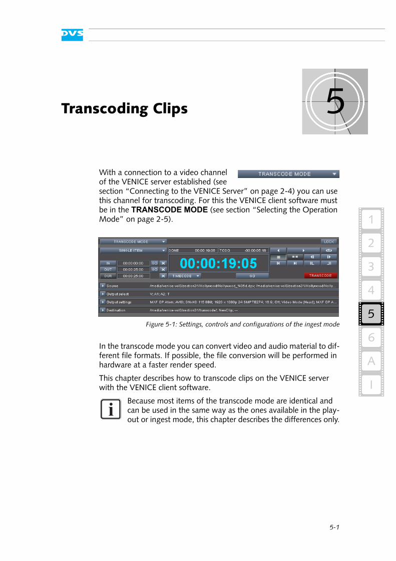
5-1
5
2
1
3
4
5
I
A
6
Transcoding Clips
With a connection to a video channel of the VENICE server established (see section “Connecting to the VENICE Server” on page 2-4) you can use this channel for transcoding. For this the VENICE client software must be in the TRANSCODE MODE (see section “Selecting the Operation Mode” on page 2-5).
Figure 5-1: Settings, controls and configurations of the ingest mode
In the transcode mode you can convert video and audio material to dif-ferent file formats. If possible, the file conversion will be performed in hardware at a faster render speed.
This chapter describes how to transcode clips on the VENICE server with the VENICE client software.
Because most items of the transcode mode are identical and can be used in the same way as the ones available in the play-out or ingest mode, this chapter describes the differences only.
5-2
VENICE Client Software User Guide
5.1 Controls Available for a Transcoding
This section describes shortly the controls and settings items that are available for a transcoding exclusively. The remaining items can be used the same way as already described for the playout and ingest mode (see chapter “Playing Out Clips” on page 3-1 and chapter “Recording Clips” on page 4-1).
5.1.1 Configuration Items
As with the other operation modes, before a transcoding can be per-formed you have to set up the operation (see also section “Configuring the Operation Mode” on page 2-6). It has to be performed same way as for the playout or ingest mode. This section describes the settings items that are available for a transcoding exclusively.
Source
With the source settings you determine the clips that should be transcoded/converted.
Output select
These items set the essences that should be converted to the other file format.
Output settings
With these settings you set the file format that the selected clips should be converted to:
Use the Target resolution setting to configure the video raster that the target video clip should provide.
This button appends the clips that are selected in the entry fields to the left to a transcoding list. If video and audio are both available, they will ap-pear as linked items in the list. With only a single item selected, only this item will be added to the list.
Inserts the clips that are selected in the entry fields to the left in the transcoding list above the item that is currently selected in the list. If video and au-dio are both available, they will appear as linked items in the list. With only a single item selected, only this item will be added to the list.

5-3
Transcoding Clips
2
1
3
4
5
I
A
6
The Auto scale and OAR (original aspect ratio) items enable you to scale and resize your original video material:
– With the combo box Auto scale set to Fit and the OAR check box activated, the original material will be scaled to its maximum allowable width or height so that no information gets lost. If the aspect ratio is different, you will receive black bars in the target files.
– With this combo box set to Crop and the OAR check box acti-vated, the images will be scaled to their maximum allowable width or height so that you receive a full image at the output. If the aspect ration is different, parts of the images may be cropped.
– With the Auto scale setting set to Off, the material will maintain its original size.
– With the combo box Auto scale set to Fit or Crop and the OAR check box deactivated, the aspect ratio will not be preserved. The resulting images will be stretched or compressed if the aspect ratio is different and you will always receive a full image in the target files.
When INTERNAL TC is selected in the field Timecode type, you can enter a timecode offset in the field Start timecode. It will be evaluated if for the clip to be generated a file format is selected that stores source timecode information (e.g. *.dpx). Then the source timecode of the target clip will start with this timecode.
Destination
With these settings you determine the storage location of the files to be created.
5.1.2 Player Controls
The player controls in the transcode mode can be used, for example, to play out the items that are currently selected as the source. They per-form the same actions as the player controls in the playout mode (see section “Player Controls (VENICE)” on page 3-14). The following user interface items are available for a transcoding only.
You can select between the transcoding of a single item or a complete transcoding list via the combo box at the top left of the controls:
Figure 5-2: Switching between single clips and transcoding list
5-4
VENICE Client Software User Guide
To start a transcoding use the following item:
A transcoding list can be created in the playlist/transcoding list editor (see section “Playlist / Transcoding List Editor” on page 6-2).
Once your transcoding is set up correctly you can start the operation with this button. Then it chang-es its appearance to its active state and the transcoding begins. In case it is necessary to termi-nate the transcoding, you have to click the button again.
5-5
Transcoding Clips
2
1
3
4
5
I
A
6
5.2 Transcoding with the VENICE Server
With the DVS software in the transcode mode you can play out the currently selected content and convert it to a different file format. To start a transcoding perform the steps as described below:
Select the video and audio content that should be transcoded with the Source items as described in section “Selecting Content for Play-out” on page 3-2.
Determine a file name and path for the file(s) to be created with the Destination items as described in section “Selecting the Storage Location and File Name” on page 4-5.
If necessary, specify the essences for the transcoding with the Out-put select items (see section “Selecting Essences for Play-out” on page 3-6).
If necessary, configure the output format to your requirements with the Output settings items (see section “Configuring the Output Settings” on page 3-7).
If wanted, set an in-/outpoint or duration for the content to be transcoded (see section “Player Controls (VENICE)” on page 3-14).
If wanted, you can use the play button ( ) of the con-trols to play out the content to be transcoded, for example, for a final check.
Once the play-out is stopped, you can start the transcoding by pressing the transcode button ( ) of the controls.
The VENICE server will then start the transcoding and as an indication for this the characters of the position field turn red. The video overlay will show you the source that is transcoded (without scaling). The area of the scrub/shuttle bar below the video overlay will show you the progress of the transcoding via a progress bar:
Figure 5-3: Progress of a transcoding
Once the progress bar reaches 100% the transcoding is finished and the operation will be stopped. You can terminate the transcoding man-ually whenever you want by clicking the transcode button once again.
Via project files or presets the software can be preconfigured for certain tasks. Then it may not be necessary to perform all the configurations described below (see section “Preconfigur-ing the VENICE Client Software” on page 2-13).

5-6
VENICE Client Software User Guide
6-1
6
6
2
1
3
I
4
5
A
Miscellaneous
The VENICE client software provides a special area where you can find several tools, for example, to administer playlists/transcoding lists or to adapt the streamed audio heard at your workstation. This chapter ex-plains the items of the tool area in detail. Furthermore, the menu bar and its options will be explained.
6-2
VENICE Client Software User Guide
6.1 Playlist / Transcoding List Editor
With the playlist/transcoding list editor you can administer and create playlists/transcoding lists.
The playlist editor will be available in the PLAYOUT MODE and the transcoding list editor in the TRANSCODE MODE (see section “Se-lecting the Operation Mode” on page 2-5). However, apart from this distinction they are in most respects identical and can be used in the same way.
Figure 6-1: Playlist/transcoding list editor
This section describes the playlist/transcoding list editor in detail.
6.1.1 Using Playlists / Transcoding Lists
Playlists and transcoding lists are interchangeable, meaning they are based on the same format and can be used in the PLAYOUT MODE as well as in the TRANSCODE MODE.
In these operation modes you can find among the player/recorder con-trols at the top left a combo box where you can specify whether a list should be used or single video/audio clips:
Figure 6-2: Switching between single clips and playlist/transcoding list
After the playlist/transcoding list has been selected, it will be processed in the selected operation mode instead of the single items. However, for
For information about playlists and transcoding lists see section “Playlists / Transcoding Lists” on page 2-14.
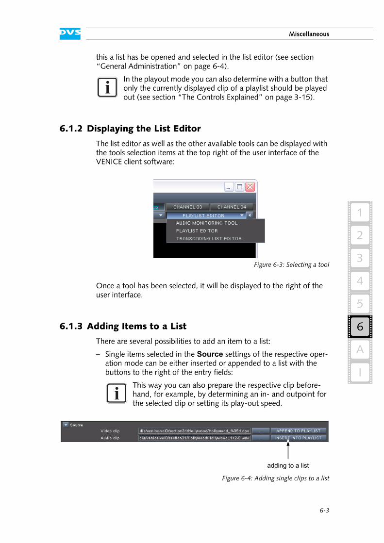
6-3
Miscellaneous
6
2
1
3
I
4
5
A
this a list has be opened and selected in the list editor (see section “General Administration” on page 6-4).
6.1.2 Displaying the List Editor
The list editor as well as the other available tools can be displayed with the tools selection items at the top right of the user interface of the VENICE client software:
Figure 6-3: Selecting a tool
Once a tool has been selected, it will be displayed to the right of the user interface.
6.1.3 Adding Items to a List
There are several possibilities to add an item to a list:
– Single items selected in the Source settings of the respective oper-ation mode can be either inserted or appended to a list with the buttons to the right of the entry fields:
Figure 6-4: Adding single clips to a list
In the playout mode you can also determine with a button that only the currently displayed clip of a playlist should be played out (see section “The Controls Explained” on page 3-15).
This way you can also prepare the respective clip before-hand, for example, by determining an in- and outpoint for the selected clip or setting its play-out speed.
adding to a list
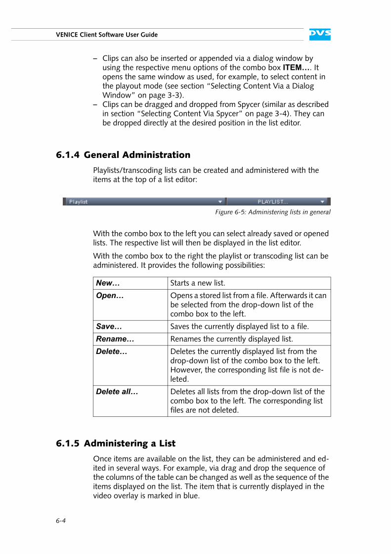
6-4
VENICE Client Software User Guide
– Clips can also be inserted or appended via a dialog window by using the respective menu options of the combo box ITEM…. It opens the same window as used, for example, to select content in the playout mode (see section “Selecting Content Via a Dialog Window” on page 3-3).
– Clips can be dragged and dropped from Spycer (similar as described in section “Selecting Content Via Spycer” on page 3-4). They can be dropped directly at the desired position in the list editor.
6.1.4 General Administration
Playlists/transcoding lists can be created and administered with the items at the top of a list editor:
Figure 6-5: Administering lists in general
With the combo box to the left you can select already saved or opened lists. The respective list will then be displayed in the list editor.
With the combo box to the right the playlist or transcoding list can be administered. It provides the following possibilities:
6.1.5 Administering a List
Once items are available on the list, they can be administered and ed-ited in several ways. For example, via drag and drop the sequence of the columns of the table can be changed as well as the sequence of the items displayed on the list. The item that is currently displayed in the video overlay is marked in blue.
New… Starts a new list.
Open… Opens a stored list from a file. Afterwards it can be selected from the drop-down list of the combo box to the left.
Save… Saves the currently displayed list to a file.
Rename… Renames the currently displayed list.
Delete… Deletes the currently displayed list from the drop-down list of the combo box to the left. However, the corresponding list file is not de-leted.
Delete all… Deletes all lists from the drop-down list of the combo box to the left. The corresponding list files are not deleted.
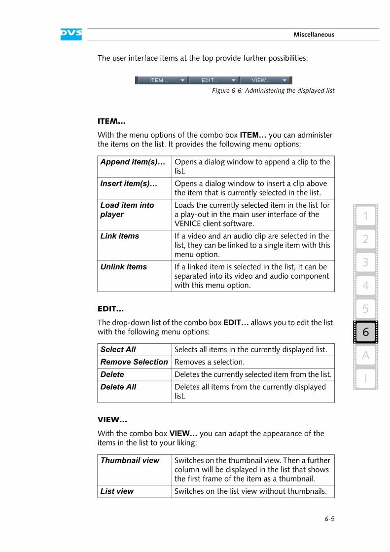
6-5
Miscellaneous
6
2
1
3
I
4
5
A
The user interface items at the top provide further possibilities:
Figure 6-6: Administering the displayed list
ITEM…
With the menu options of the combo box ITEM… you can administer the items on the list. It provides the following menu options:
EDIT…
The drop-down list of the combo box EDIT… allows you to edit the list with the following menu options:
VIEW…
With the combo box VIEW… you can adapt the appearance of the items in the list to your liking:
Append item(s)… Opens a dialog window to append a clip to the list.
Insert item(s)… Opens a dialog window to insert a clip above the item that is currently selected in the list.
Load item into player
Loads the currently selected item in the list for a play-out in the main user interface of the VENICE client software.
Link items If a video and an audio clip are selected in the list, they can be linked to a single item with this menu option.
Unlink items If a linked item is selected in the list, it can be separated into its video and audio component with this menu option.
Select All Selects all items in the currently displayed list.
Remove Selection Removes a selection.
Delete Deletes the currently selected item from the list.
Delete All Deletes all items from the currently displayed list.
Thumbnail view Switches on the thumbnail view. Then a further column will be displayed in the list that shows the first frame of the item as a thumbnail.
List view Switches on the list view without thumbnails.
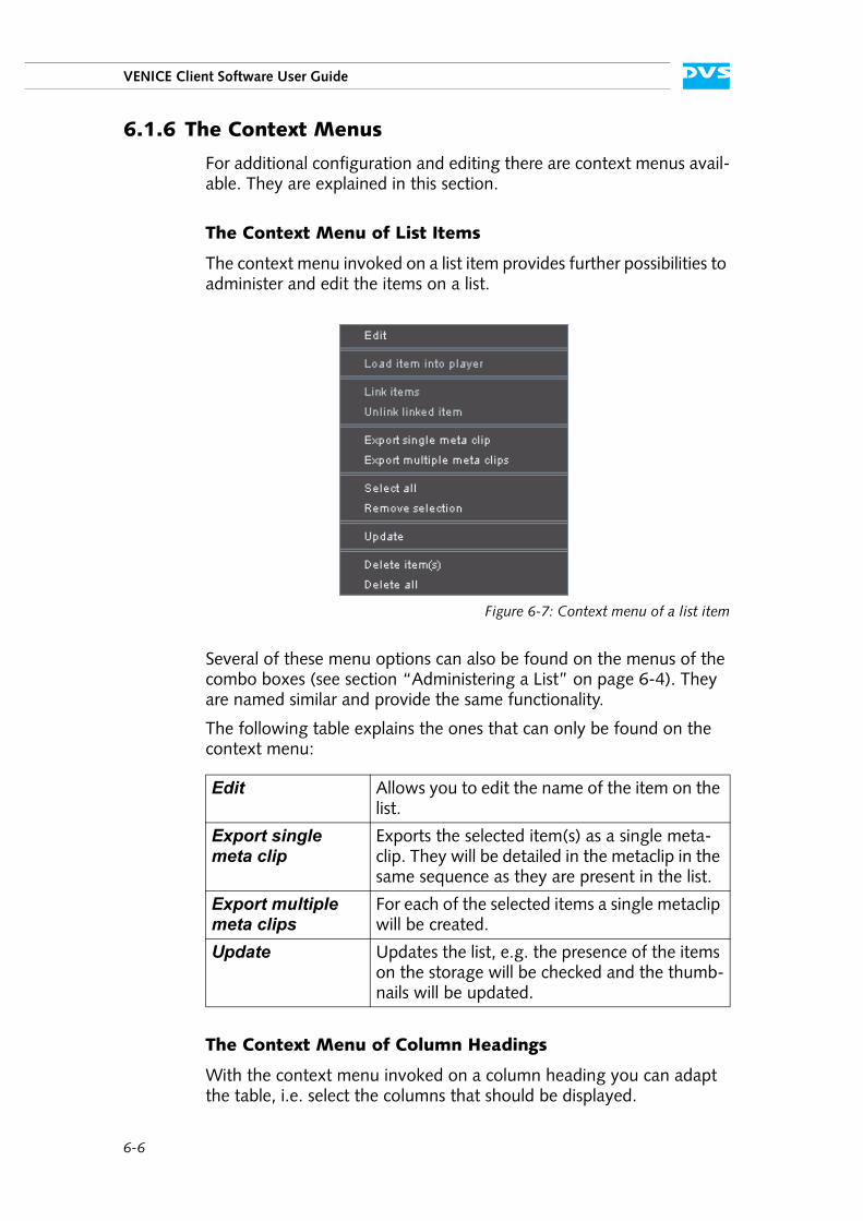
6-6
VENICE Client Software User Guide
6.1.6 The Context Menus
For additional configuration and editing there are context menus avail-able. They are explained in this section.
The Context Menu of List Items
The context menu invoked on a list item provides further possibilities to administer and edit the items on a list.
Figure 6-7: Context menu of a list item
Several of these menu options can also be found on the menus of the combo boxes (see section “Administering a List” on page 6-4). They are named similar and provide the same functionality.
The following table explains the ones that can only be found on the context menu:
The Context Menu of Column Headings
With the context menu invoked on a column heading you can adapt the table, i.e. select the columns that should be displayed.
Edit Allows you to edit the name of the item on the list.
Export single meta clip
Exports the selected item(s) as a single meta-clip. They will be detailed in the metaclip in the same sequence as they are present in the list.
Export multiple meta clips
For each of the selected items a single metaclip will be created.
Update Updates the list, e.g. the presence of the items on the storage will be checked and the thumb-nails will be updated.
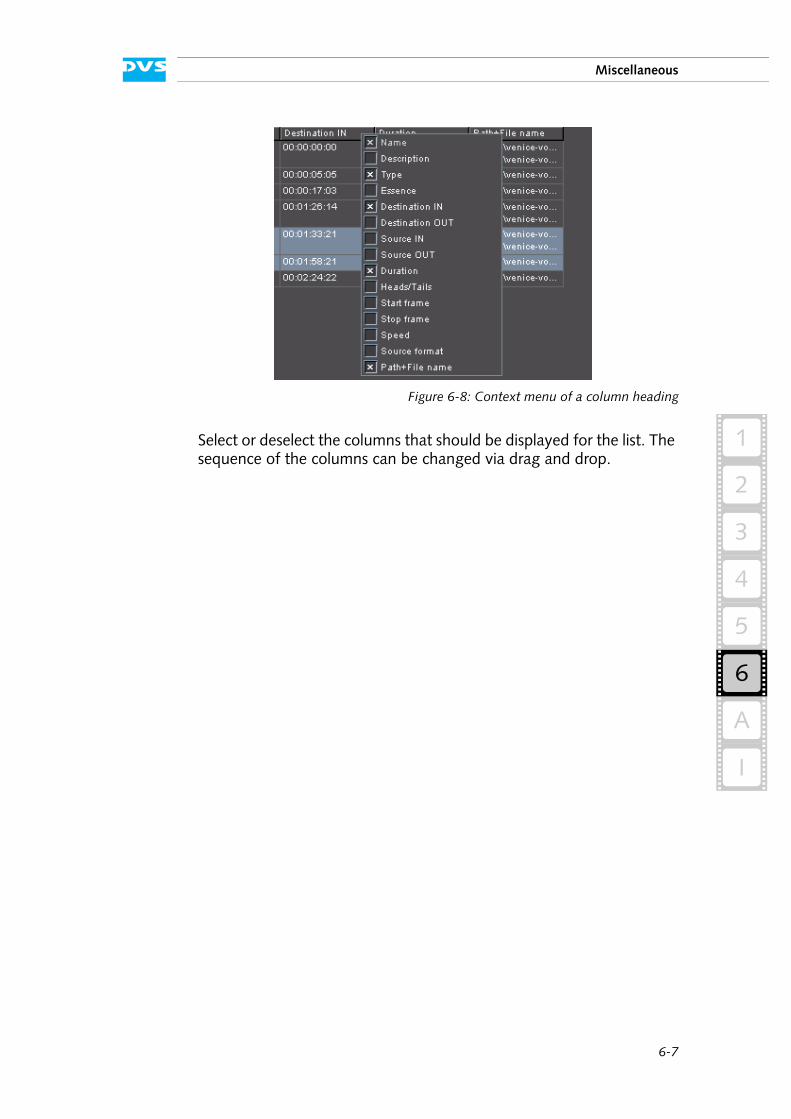
6-7
Miscellaneous
6
2
1
3
I
4
5
A
Figure 6-8: Context menu of a column heading
Select or deselect the columns that should be displayed for the list. The sequence of the columns can be changed via drag and drop.
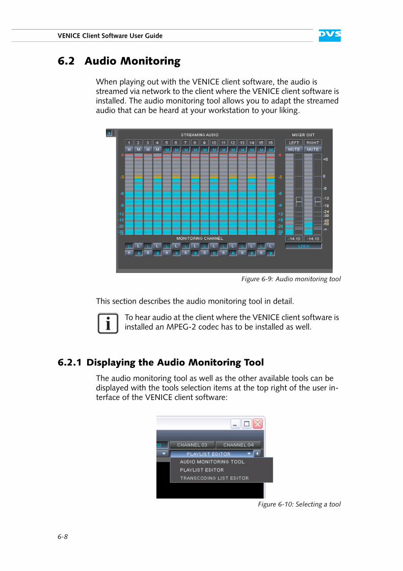
6-8
VENICE Client Software User Guide
6.2 Audio Monitoring
When playing out with the VENICE client software, the audio is streamed via network to the client where the VENICE client software is installed. The audio monitoring tool allows you to adapt the streamed audio that can be heard at your workstation to your liking.
Figure 6-9: Audio monitoring tool
This section describes the audio monitoring tool in detail.
6.2.1 Displaying the Audio Monitoring Tool
The audio monitoring tool as well as the other available tools can be displayed with the tools selection items at the top right of the user in-terface of the VENICE client software:
Figure 6-10: Selecting a tool
To hear audio at the client where the VENICE client software is installed an MPEG-2 codec has to be installed as well.
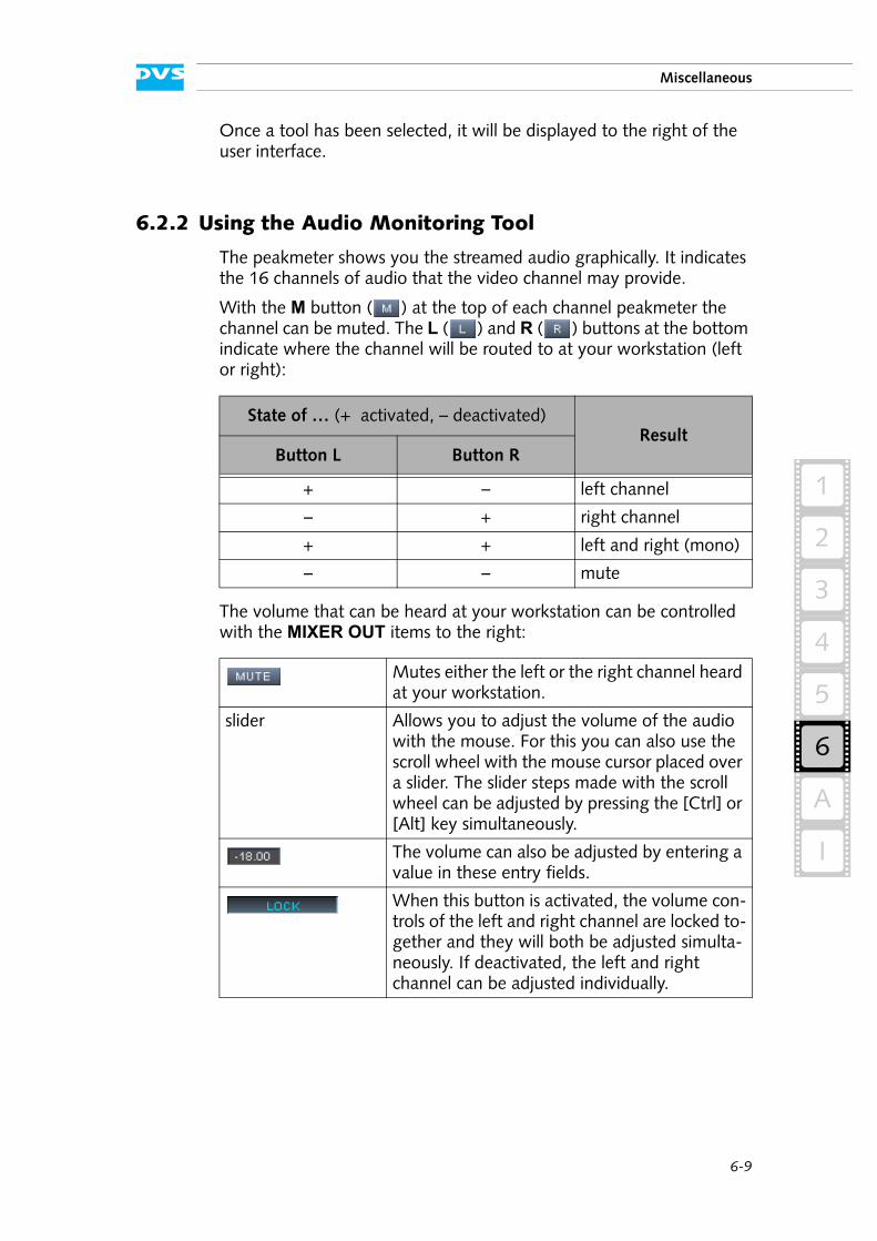
6-9
Miscellaneous
6
2
1
3
I
4
5
A
Once a tool has been selected, it will be displayed to the right of the user interface.
6.2.2 Using the Audio Monitoring Tool
The peakmeter shows you the streamed audio graphically. It indicates the 16 channels of audio that the video channel may provide.
With the M button ( ) at the top of each channel peakmeter the channel can be muted. The L ( ) and R ( ) buttons at the bottom indicate where the channel will be routed to at your workstation (left or right):
The volume that can be heard at your workstation can be controlled with the MIXER OUT items to the right:
State of … (+ activated, – deactivated)Result
Button L Button R
+ – left channel
– + right channel
+ + left and right (mono)
– – mute
Mutes either the left or the right channel heard at your workstation.
slider Allows you to adjust the volume of the audio with the mouse. For this you can also use the scroll wheel with the mouse cursor placed over a slider. The slider steps made with the scroll wheel can be adjusted by pressing the [Ctrl] or [Alt] key simultaneously.
The volume can also be adjusted by entering a value in these entry fields.
When this button is activated, the volume con-trols of the left and right channel are locked to-gether and they will both be adjusted simulta-neously. If deactivated, the left and right channel can be adjusted individually.
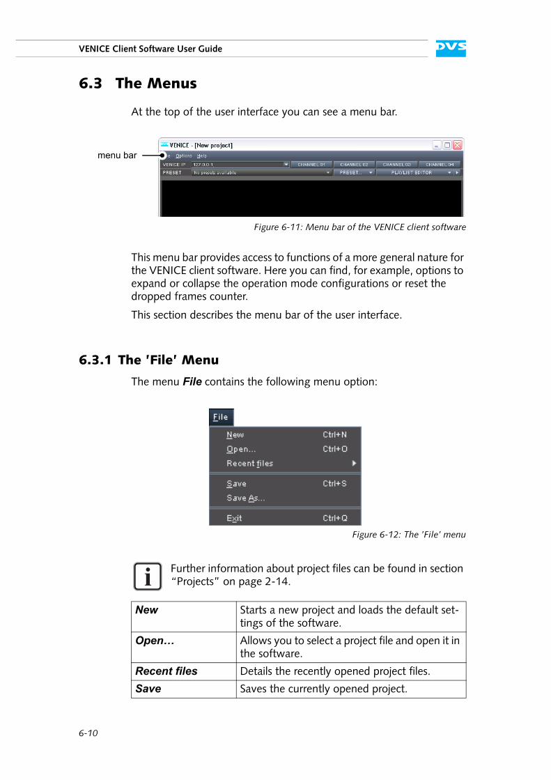
6-10
VENICE Client Software User Guide
6.3 The Menus
At the top of the user interface you can see a menu bar.
Figure 6-11: Menu bar of the VENICE client software
This menu bar provides access to functions of a more general nature for the VENICE client software. Here you can find, for example, options to expand or collapse the operation mode configurations or reset the dropped frames counter.
This section describes the menu bar of the user interface.
6.3.1 The ’File’ Menu
The menu File contains the following menu option:
Figure 6-12: The ’File’ menu
Further information about project files can be found in section “Projects” on page 2-14.
New Starts a new project and loads the default set-tings of the software.
Open… Allows you to select a project file and open it in the software.
Recent files Details the recently opened project files.
Save Saves the currently opened project.
menu bar
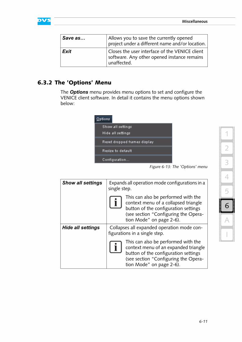
6-11
Miscellaneous
6
2
1
3
I
4
5
A
6.3.2 The ’Options’ Menu
The Options menu provides menu options to set and configure the VENICE client software. In detail it contains the menu options shown below:
Figure 6-13: The ’Options’ menu
Save as… Allows you to save the currently opened project under a different name and/or location.
Exit Closes the user interface of the VENICE client software. Any other opened instance remains unaffected.
Show all settings Expands all operation mode configurations in a single step.
This can also be performed with the context menu of a collapsed triangle button of the configuration settings (see section “Configuring the Opera-tion Mode” on page 2-6).
Hide all settings Collapses all expanded operation mode con-figurations in a single step.
This can also be performed with the context menu of an expanded triangle button of the configuration settings (see section “Configuring the Opera-tion Mode” on page 2-6).
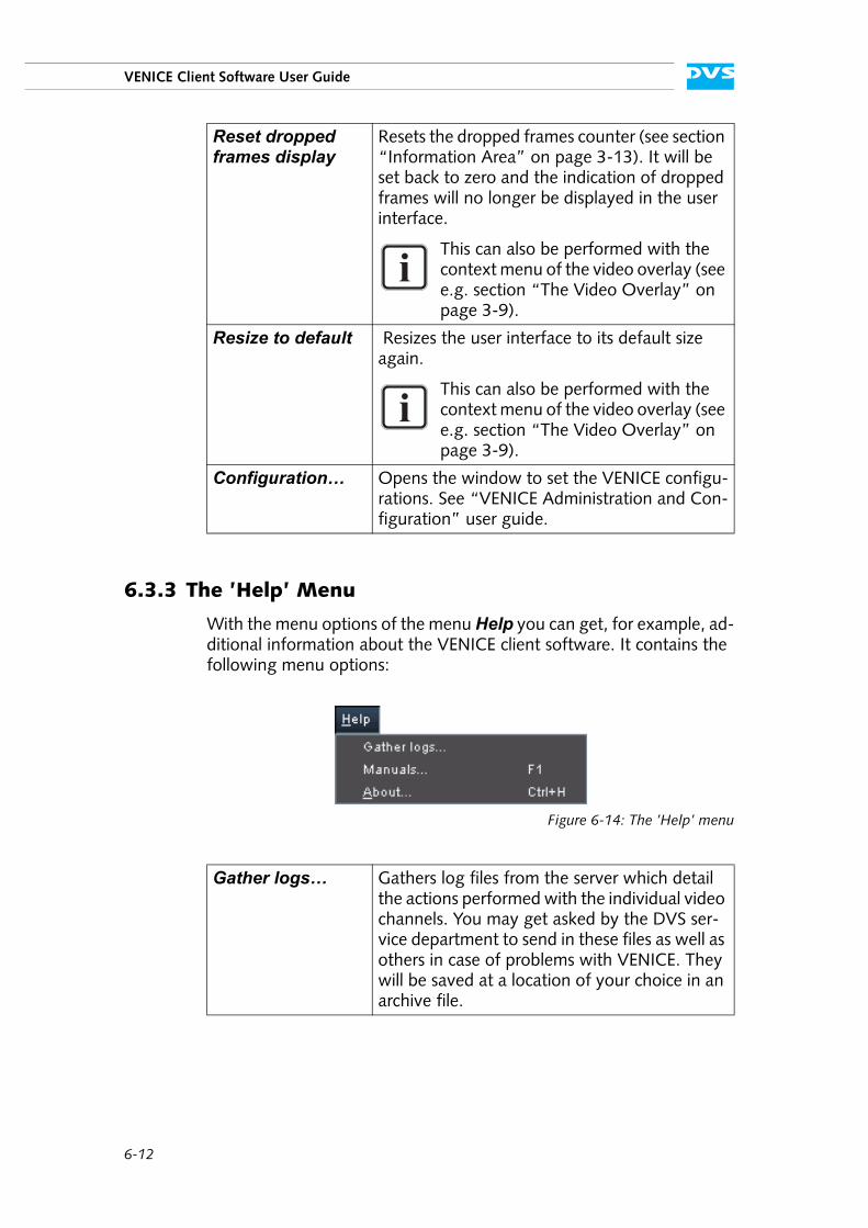
6-12
VENICE Client Software User Guide
6.3.3 The ’Help’ Menu
With the menu options of the menu Help you can get, for example, ad-ditional information about the VENICE client software. It contains the following menu options:
Figure 6-14: The ’Help’ menu
Reset dropped frames display
Resets the dropped frames counter (see section “Information Area” on page 3-13). It will be set back to zero and the indication of dropped frames will no longer be displayed in the user interface.
This can also be performed with the context menu of the video overlay (see e.g. section “The Video Overlay” on page 3-9).
Resize to default Resizes the user interface to its default size again.
This can also be performed with the context menu of the video overlay (see e.g. section “The Video Overlay” on page 3-9).
Configuration… Opens the window to set the VENICE configu-rations. See “VENICE Administration and Con-figuration” user guide.
Gather logs… Gathers log files from the server which detail the actions performed with the individual video channels. You may get asked by the DVS ser-vice department to send in these files as well as others in case of problems with VENICE. They will be saved at a location of your choice in an archive file.
6-13
Miscellaneous
6
2
1
3
I
4
5
A
Manuals… Accesses the online documentation of VENICE. It opens an overview page in HTML format.
The manuals are also available in PDF format which is suited best if you want to print out the document.
About… Displays further information about the VENICE client software, for example, the precise ver-sion number of the software or additional li-cense information.

6-14
VENICE Client Software User Guide
A-1
A
A
2
1
3
I
4
5
6
Appendix
This chapter provides further information about the software. Among others you can find here lists of the available keyboard shortcuts and the file formats that are supported directly by the DVS software.
A.1 Keyboard Shortcuts
For a more easy and a faster control of the VENICE client software there are various keyboard shortcuts available which are listed in the tables below:
For the shortcuts to work the focus must be set correctly. It should be on the controls in general or the scrub/shuttle bar.
Table A-1: General keyboard shortcuts
Action Shortcut
Switch between operation modes [Ctrl + Shift + TAB]
Switch between player/recorder controls
[Ctrl + TAB]
Start record (crash and autoedit) [Ctrl + Shift +R]
Play (speed 1) [Space], [L], [5], [’]
Stop play (speed 0) [Space], [K]
Step one (1) frame backward [Left Arrow], [3], [,]
Step one (1) frame forward [Right Arrow], [4], [.]
Set inpoint [E], [I]
Set outpoint [R], [O]
Delete inpoint [D]
Delete outpoint [F]
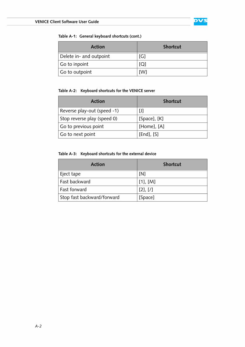
A-2
VENICE Client Software User Guide
Delete in- and outpoint [G]
Go to inpoint [Q]
Go to outpoint [W]
Table A-2: Keyboard shortcuts for the VENICE server
Action Shortcut
Reverse play-out (speed -1) [J]
Stop reverse play (speed 0) [Space], [K]
Go to previous point [Home], [A]
Go to next point [End], [S]
Table A-3: Keyboard shortcuts for the external device
Action Shortcut
Eject tape [N]
Fast backward [1], [M]
Fast forward [2], [/]
Stop fast backward/forward [Space]
Table A-1: General keyboard shortcuts (cont.)
Action Shortcut
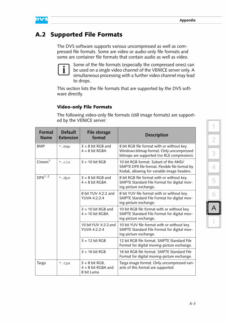
A-3
Appendix
A
2
1
3
I
4
5
6
A.2 Supported File Formats
The DVS software supports various uncompressed as well as com-pressed file formats. Some are video or audio-only file formats and some are container file formats that contain audio as well as video.
This section lists the file formats that are supported by the DVS soft-ware directly.
Video-only File Formats
The following video-only file formats (still image formats) are support-ed by the VENICE server:
Some of the file formats (especially the compressed ones) can be used on a single video channel of the VENICE server only. A simultaneous processing with a further video channel may lead to drops.
Format Name
DefaultExtension
File storage format
Description
BMP *.bmp 3 × 8 bit RGB and 4 × 8 bit RGBA
8 bit RGB file format with or without key. Windows bitmap format. Only uncompressed bitmaps are supported (no RLE compression).
Cineon1 *.cin 3 × 10 bit RGB 10 bit RGB format. Subset of the ANSI/SMPTE DPX file format. Flexible file format by Kodak, allowing for variable image headers.
DPX1, 2 *.dpx 3 × 8 bit RGB and 4 × 8 bit RGBA
8 bit RGB file format with or without key. SMPTE Standard File Format for digital mov-ing-picture exchange.
8 bit YUV 4:2:2 and YUVA 4:2:2:4
8 bit YUV file format with or without key. SMPTE Standard File Format for digital mov-ing-picture exchange.
3 × 10 bit RGB and 4 × 10 bit RGBA
10 bit RGB file format with or without key. SMPTE Standard File Format for digital mov-ing-picture exchange.
10 bit YUV 4:2:2 and YUVA 4:2:2:4
10 bit YUV file format with or without key. SMPTE Standard File Format for digital mov-ing-picture exchange.
3 × 12 bit RGB 12 bit RGB file format. SMPTE Standard File Format for digital moving-picture exchange.
3 × 16 bit RGB 16 bit RGB file format. SMPTE Standard File Format for digital moving-picture exchange.
Targa *.tga 3 × 8 bit RGB, 4 × 8 bit RGBA and 8 bit Luma
Targa image format. Only uncompressed vari-ants of this format are supported.
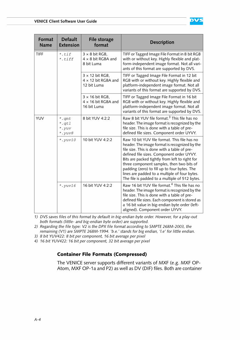
A-4
VENICE Client Software User Guide
Container File Formats (Compressed)
The VENICE server supports different variants of MXF (e.g. MXF OP-Atom, MXF OP-1a and P2) as well as DV (DIF) files. Both are container
TIFF *.tif *.tiff
3 × 8 bit RGB, 4 × 8 bit RGBA and 8 bit Luma
TIFF or Tagged Image File Format in 8 bit RGB with or without key. Highly flexible and plat-form-independent image format. Not all vari-ants of this format are supported by DVS.
3 × 12 bit RGB, 4 × 12 bit RGBA and 12 bit Luma
TIFF or Tagged Image File Format in 12 bit RGB with or without key. Highly flexible and platform-independent image format. Not all variants of this format are supported by DVS.
3 × 16 bit RGB, 4 × 16 bit RGBA and 16 bit Luma
TIFF or Tagged Image File Format in 16 bit RGB with or without key. Highly flexible and platform-independent image format. Not all variants of this format are supported by DVS.
YUV *.qnt *.qtl *.yuv *.yuv8
8 bit YUV 4:2:2 Raw 8 bit YUV file format.3 This file has no header. The image format is recognized by the file size. This is done with a table of pre-defined file sizes. Component order UYVY.
*.yuv10 10 bit YUV 4:2:2 Raw 10 bit YUV file format. This file has no header. The image format is recognized by the file size. This is done with a table of pre-defined file sizes. Component order UYVY. Bits are packed tightly from left to right for three component samples, then two bits of padding (zero) to fill up to four bytes. The lines are padded to a multiple of four bytes. The file is padded to a multiple of 512 bytes.
*.yuv16 16 bit YUV 4:2:2 Raw 16 bit YUV file format.4 This file has no header. The image format is recognized by the file size. This is done with a table of pre-defined file sizes. Each component is stored as a 16 bit value in big-endian byte order (left-aligned). Component order UYVY.
1) DVS saves files of this format by default in big-endian byte order. However, for a play-out both formats (little- and big-endian byte order) are supported.
2) Regarding the file type: V2 is the DPX file format according to SMPTE 268M-2003, the remaining (V1) are SMPTE 268M-1994. ’b.e.’ stands for big endian, ’l.e’ for little endian.
3) 8 bit YUV422: 8 bit per component, 16 bit average per pixel4) 16 bit YUV422: 16 bit per component, 32 bit average per pixel
Format Name
DefaultExtension
File storage format
Description
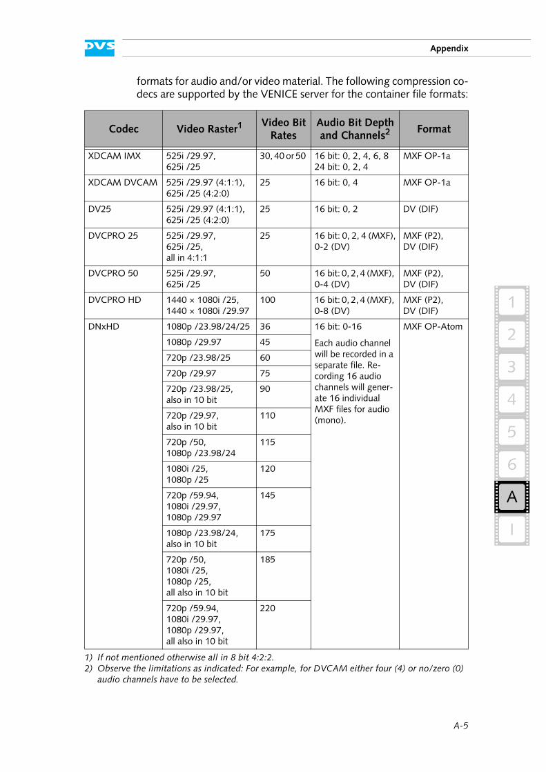
A-5
Appendix
A
2
1
3
I
4
5
6
formats for audio and/or video material. The following compression co-decs are supported by the VENICE server for the container file formats:
Codec Video Raster1
1) If not mentioned otherwise all in 8 bit 4:2:2.
Video Bit Rates
Audio Bit Depth and Channels2
2) Observe the limitations as indicated: For example, for DVCAM either four (4) or no/zero (0) audio channels have to be selected.
Format
XDCAM IMX 525i /29.97,625i /25
30, 40 or 50 16 bit: 0, 2, 4, 6, 824 bit: 0, 2, 4
MXF OP-1a
XDCAM DVCAM 525i /29.97 (4:1:1),625i /25 (4:2:0)
25 16 bit: 0, 4 MXF OP-1a
DV25 525i /29.97 (4:1:1),625i /25 (4:2:0)
25 16 bit: 0, 2 DV (DIF)
DVCPRO 25 525i /29.97,625i /25,all in 4:1:1
25 16 bit: 0, 2, 4 (MXF),0-2 (DV)
MXF (P2),DV (DIF)
DVCPRO 50 525i /29.97,625i /25
50 16 bit: 0, 2, 4 (MXF), 0-4 (DV)
MXF (P2),DV (DIF)
DVCPRO HD 1440 × 1080i /25,1440 × 1080i /29.97
100 16 bit: 0, 2, 4 (MXF), 0-8 (DV)
MXF (P2),DV (DIF)
DNxHD 1080p /23.98/24/25 36 16 bit: 0-16
Each audio channel will be recorded in a separate file. Re-cording 16 audio channels will gener-ate 16 individual MXF files for audio (mono).
MXF OP-Atom
1080p /29.97 45
720p /23.98/25 60
720p /29.97 75
720p /23.98/25,also in 10 bit
90
720p /29.97,also in 10 bit
110
720p /50,1080p /23.98/24
115
1080i /25,1080p /25
120
720p /59.94,1080i /29.97,1080p /29.97
145
1080p /23.98/24,also in 10 bit
175
720p /50,1080i /25,1080p /25,all also in 10 bit
185
720p /59.94,1080i /29.97,1080p /29.97,all also in 10 bit
220
A-6
VENICE Client Software User Guide
Audio-only File Formats
The following uncompressed audio-only file formats are supported by the VENICE server:
Format NameDefault
ExtensionDescription
AIFAIFF
*.aif *.aiff
Audio interchange format. Platform-inde-pendent file format for sound. Capable of storing multiple mono or stereo channels.
BWF *.rf64 *.wav
Broadcast wave format. Platform-indepen-dent file format for sound. Extension of the Wave format capable of storing multiple mono or stereo channels together with metadata and enabling file sizes of more than 4 GB.
Wave *.wav File format for digital audio (waveform) data under Windows. Capable of storing multiple mono or stereo channels.
A-7
Appendix
A
2
1
3
I
4
5
6
A.3 States of an External Device
An externally connected device can go into different states that are all shown in the RS-422 STATUS field of the user interface (see section “Information Area” on page 3-13). You can control an external device via the remote output of the DVS system, such as telecines, VTRs or digital disk recorders. The following shows the most important statuses that will be displayed by the DVS software:
Additionally, some error messages are available and the following ones can be displayed by the DVS software:
OFFLINE No external device connected
STANDBY Device is in standby mode
LOCAL External device is controlled from its own oper-ation panel; all RS-422 commands are ignored
STILL Tape has stopped but is still threaded with the video drum head turning (standby on)
STOP Tape has stopped and is unthreaded, the video drum head has stopped as well (standby off)
EJECT Device is ejecting the tape
REWIND Tape is rewound
FORWARD Tape is fast forwarded
RECORD Device is recording
PLAY Device is playing out
JOG Tape is forwarded or rewound (speeds (±) 0.1 to 1)
SHUTTLE Tape is fast forwarded or rewound (speeds (±) 1.1 to 10)
PREROLL Device is performing the preroll
TAPE UNTHREAD No tape loaded
TAPE TROUBLE A tape error has occurred
HARD ERROR A hardware error has occurred

A-8
VENICE Client Software User Guide
I-1
I
I
2
1
3
4
5
A
6
Index
A
AIV ............................................. 2-18alpha channel ................................ 3-6appending to list ............................ 6-3aspect ratio .............................3-9, 4-9assemble mode ............................ 3-18asterisk (timecode) ....................... 2-16audio .......................................... 2-18
bit depth .................................. 4-5Broadcast Wave ..................... 2-19channels ...........................3-6, 4-3embedded ............................. 2-18file format ........................ 4-5, A-6input ..............................2-18, 4-3monitoring ......................2-18, 6-8peakmeter ............................. 2-18play-out .........................2-18, 3-6record ............................2-18, 4-3sampling rate ..................2-18, 4-5source timecode ..................... 2-19volume .................................... 6-9
audio monitoring tool ..................... 6-8display ..................................... 6-8scroll wheel .............................. 6-9usage ...................................... 6-9volume .................................... 6-9
autoedit record 3-15, 3-21, 4-12, 4-15autoscaling .................................... 5-3
B
back-to-back mode ...................... 3-17bit depth
audio ...................................... 4-5video ....................................... 4-4
Broadcast Wave ........................... 2-19browsing pane ................ 3-3, 3-4, 4-7
buttonALPHA ONLY ...........................3-6audio channels ...................3-6, 4-3AUTO EDIT ..3-18, 3-22, 4-17, 5-4Autodetect ...............................4-2back-to-back ..........................3-17CLOSE .......2-10, 2-11, 3-23, 4-18delete IN/OUT/DUR ...............3-16DUR ......................................3-16eject ......................................3-17fast backward .........................3-18fast forward ...........................3-18frame backward ......................3-17frame forward ........................3-17GO ...............................3-16, 3-17IN ...................... 3-16, 3-22, 4-14Load project .............................2-5LOCK ....................................2-11Lock to video input ...................3-7New project .............................2-5next point ..............................3-17OUT ................... 3-16, 3-22, 4-14pause record ..................4-12, 4-15play ...................... 3-17, 3-20, 5-5previous point .........................3-17record .. 2-11, 3-18, 4-15, 5-4, 5-5reverse play ............................3-17SLAVE .................. 2-9, 3-23, 4-18stop .......................................3-17TRANSCODE ............................5-4
byte order ......................................4-4
C
C notation .....................................3-3capacity (storage) ....................1-5, 4-5channel connection settings .............2-4chapter overview ............................1-2codec .................................... 4-4, A-5
I-2
VENICE Client Software User Guide
collapse configurations .................... 2-7all ..................................2-7, 6-11
color spaceconversion ............................... 4-4range ...................................... 4-4scaling ..................................... 4-4
compression type ........................... 4-4configuring
a play-out ................................ 3-2a record ................................... 4-2a transcoding ........................... 5-2operation mode ........................ 2-6VENICE ................................. 6-12
connecting to a video channel .......... 2-4consecutive number .................4-6, 4-8container format .................... 4-5, A-4
file name ................................. 4-8context menu ............. 3-10, 4-10, 6-6conventions
of user guide ............................ 1-3screenshots .............................. 1-4
crash record .....3-15, 3-20, 4-11, 4-14pause ...........................4-12, 4-15
creatingmetaclip .................. 2-15, 4-7, 6-6playlist ..................................... 6-4transcoding list ......................... 6-4
cropped images .....................3-10, 4-9cursor (scrub bar) ......................... 3-11
D
data management .......................... 3-4default size .................................. 6-12delete inpoint/outpoint/duration .... 3-16direction of transfer ........................ 2-6directory tree ..........................3-4, 4-7disconnecting/freeing ................... 2-12disk capacity .................................. 4-5disk space (used/free) ..................... 4-5display mode (frames/fields) .......... 3-17drop-frame timecode .................... 2-16dropped frames ....3-9, 3-13, 4-9, 4-13dropped frames counter ................ 3-13
reset ................... 3-10, 4-10, 6-12duration ................... 3-16, 3-20, 4-15
delete .................................... 3-16
E
eject tape .................................... 3-17
elapsed time .................................3-16embedded audio ...........................2-18entering timecode .........................2-17error message ....................... 2-4, 2-12essence
for play-out ..............................3-6for record .................................4-3
exiting the program ............ 2-15, 6-11expand configurations .....................2-7
all .................................. 2-7, 6-11extension of files ........ 2-13, 2-14, 2-15external device (RS-422) ..................1-1
assemble mode .......................3-18autoedit record ............. 3-15, 3-21control ...................................4-13crash record .................. 3-15, 3-20insert mode ............................3-18player controls ........................4-11play-out .................................4-13record ....................................3-20recorder controls .....................3-14shuttle bar .................... 3-11, 4-10state .............................. 3-13, A-7timecode information ..............3-18
F
fast backward ...............................3-18fast forward .................................3-18fast motion ..................................3-12fields display mode .......................3-17file extension ......2-13, 2-14, 2-15, 4-6file format .............................. 4-4, A-3
audio ............................. 2-18, 4-5video .......................................4-4
file name ............................... 3-2, 4-5C notation ................................3-3default .....................................4-6numbering ....................... 4-6, 4-8same ............................... 4-6, 4-8
file settings ....................................4-4file type .........................................4-4frame backward ...........................3-17frame forward ..............................3-17frame number .................... 2-17, 3-16frame number/timecode field .........2-17
switch notation ............. 2-17, 3-16frame rate ....................................2-16frames ............................... 2-17, 3-16frames display mode .....................3-17full ................................................4-4
I-3
Index
I
2
1
3
4
5
A
6
G
general usage ................................ 2-3generic source timecode ................ 2-19go
see move
H
hardware support (transcoding) ....... 5-1head ............................................. 4-4hide settings ................................ 6-11
see also collapse
I
important notes ............................. 1-5information area .................3-13, 4-10ingest
see recordingest mode ...........................2-5, 4-1
input settings ........................... 3-7slave mode control window ..... 2-10video overlay ........................... 4-9
inpoint ...............................3-16, 4-14delete .................................... 3-16move to ................................. 3-16
input (audio) .........................2-18, 4-3input format .................................. 4-2input port ...................................... 4-2input select .................................... 4-3input settings ................................. 4-2insert mode ..........................3-7, 3-18inserting in list ................................ 6-3instances of the software ..........2-2, 2-4instructions
exiting program ...................... 2-15play-out ................................ 3-19record ................................... 4-13starting under Linux .................. 2-2starting under Mac ................... 2-2starting under Windows ............ 2-2transcoding .............................. 5-5using the software .................... 2-3
J
jog ............................................. 3-12
K
key ............................................... 3-6
keyboard shortcuts .........................A-1
L
license information .......................6-13list editor
appearance .......................6-4, 6-6append item ......................5-2, 6-3display .....................................6-3editing ..............................6-4, 6-6insert item .........................5-2, 6-3Spycer .....................................6-4
lock user interface .........................2-11unlock ...................................2-11
log files .......................................6-12loop mode ...................................3-17LTC ...............................................3-6
M
main storage ..................................1-5manuals ......................................6-13menu bar .....................................6-10metaclip ......................................2-15
create ..................... 2-15, 4-7, 6-6mode
assemble ................................3-18autoedit .....3-15, 3-21, 4-12, 4-15crash record 3-15, 3-20, 4-11, 4-14ingest ...............................2-5, 4-1insert ..............................3-7, 3-18loop ......................................3-17playout .............................2-5, 3-1slave ..................... 2-9, 3-23, 4-17transcode ..........................2-5, 5-1
monitoring audio ...................2-18, 6-8move in material ...........................3-11move to in-/outpoint ....................3-16move to position ..........................3-17
N
new directory ..........................4-6, 4-7next point ....................................3-17notes .............................................1-5
O
OAR .............................................5-3operation mode ..............................2-5
roles ........................................2-6
I-4
VENICE Client Software User Guide
operation mode configurations ........ 2-6collapse ................................... 2-7collapse all ......................2-7, 6-11expand .................................... 2-7expand all .......................2-7, 6-11
outpoint .............................3-16, 4-14delete .................................... 3-16move to ................................. 3-16
output content ............................... 3-2dialog window .......................... 3-3manual setting .......................... 3-2preview ................................... 3-4Spycer ..................................... 3-4
output format ................................ 3-7output port .................................... 3-7output select .........................3-6, 3-18output settings ........................3-7, 4-4overview of chapters ....................... 1-2
P
P2 ........................................ 4-8, A-4path .......................................3-2, 4-5pause record .......................4-12, 4-15peakmeter ................................... 2-18
audio monitoring tool ................ 6-9player controls ....................3-14, 4-11
ingest mode ........................... 4-11playout mode ......................... 3-14reference ............................... 3-15trancode mode ......................... 5-3video overlay ............................ 3-9
playlist .................................2-14, 6-2back-to-back .......................... 3-17create ...................................... 6-4play out ..........................3-15, 6-2
playlist editorsee list editor
play-out .............................. 3-1, 3-19see also outputalpha channel ...........................3-6audio ............................. 2-18, 3-6configurations ...........................3-2content ....................................3-2essence ....................................3-6external device ........................4-13fast (shuttle) ...........................3-11format .....................................3-7output settings ..........................3-7player controls ........................3-14playlist ........................... 3-15, 6-2position of play-out .................3-16recorder controls .....................3-14reverse ...................................3-17single item ...................... 3-15, 6-2slave mode .............................3-23slow (jog) ...............................3-11speed .....................................3-18start .......................................3-17video .......................................3-6
playout mode ......................... 2-5, 3-1output settings ..........................3-7slave mode control window ........2-9video overlay ............................3-9
position .......................................3-16of record ................................2-11
postroll ........................................3-18preconfiguration ...........................2-13preroll .........................................3-18preset ..........................................2-13
using presets ..........................2-13preview output content ...................3-4previous point ..............................3-17program exit ...................... 2-15, 6-11program start .................................2-2
under Linux ..............................2-2under Mac ...............................2-2under Windows ........................2-2
project ............................... 2-14, 6-10select .......................................2-5
protocol (RS-422) ................. 2-9, 2-10
R
real-time performance .....................1-5
I-5
Index
I
2
1
3
4
5
A
6
record ......................................... 4-13audio .............................2-18, 4-3configurations .......................... 4-2essence .................................... 4-3file format ................................ 4-4file name ................................. 4-5format ..................................... 4-2input settings ....................3-7, 4-2output settings ......................... 4-4path ........................................ 4-5player controls ........................ 4-11position ........................2-11, 3-16recorder controls ..................... 4-11result ....................................... 4-7same file name ..................4-6, 4-8slave mode ............................ 4-17start ...............................3-18, 5-4storage of files .......................... 4-7video ....................................... 4-3
record file name ............................. 4-5manual setting ......................... 4-6
record path .................................... 4-5dialog window ......................... 4-7manual setting ......................... 4-6Spycer ..................................... 4-7
recorder controls .................3-14, 4-11ingest mode ........................... 4-11playout mode ......................... 3-14reference ............................... 3-15video overlay ........................... 3-9
remaining time ............................. 3-16remote output ............................. 3-13reset dropped frames counter ....... 3-10,
4-10, 6-12resize user interface ... 3-10, 4-10, 6-12resizing of material ......................... 5-3review material ...................4-15, 4-17role ............................................... 2-6RS-422 ......................................... 2-9
protocol ..........................2-9, 2-10status ............................ 3-13, A-7
S
sampling rate (audio) .............2-18, 4-5scaling (auto) ................................. 5-3
scroll wheelaudio monitoring tool ................6-9shuttle bar ..............................3-12
scrub bar .....................................3-11selecting a project ...........................2-5shortcuts .......................................A-1shuttle .........................................3-12shuttle bar ..........................3-11, 4-10
scroll wheel ............................3-12single item
play out ..........................3-15, 6-2transcoding .......................5-3, 6-2
slave mode ....................................2-9control window .........................2-9exit ...............................2-10, 2-11play-out .................................3-23record ....................................4-17RS-422 protocol ...............2-9, 2-10
slow motion .................................3-12snapshot ......................................2-14Sony 9-pin ............................2-9, 2-10source timecode ...........................2-19
audio .....................................2-19generic ..................................2-19
speed .................................3-12, 3-18Spycer ...........................................4-7
adding item to list .....................6-4data management .....................3-4selecting a record path ...............4-7selecting directories/files .....3-3, 3-4selecting output content ............3-4watch folders ............................3-4
start timecode ................................5-3starting of program .........................2-2
under Linux ..............................2-2under Mac ...............................2-2under Windows ........................2-2
state of external device (RS-422) ......A-7still image format .................... 4-8, A-3storage ..........................................1-5
capacity ............................1-5, 4-5location .............3-3, 3-5, 4-6, 4-7
T
target group ..................................1-3third-party software ........................1-5
I-6
VENICE Client Software User Guide
timecode ..................................... 2-19asterisk .................................. 2-16drop-frame ............................ 2-16entering ................................. 2-17entries ................................... 2-16format ................................... 2-16greater 30 Hz ......................... 2-16notation ........................2-17, 3-16on tape .................................. 3-18record on external device ........... 3-6settings .............................3-8, 4-3source ................................... 2-19start ........................................ 5-3switch notation ..............2-17, 3-16
timecode/frame number field ........ 2-17timeline .................... 3-14, 3-15, 4-11
loop mode ............................. 3-17play ....................................... 3-17previous/next point ................. 3-17reverse play ............................ 3-17timeline begin ......................... 3-17timeline end ........................... 3-17
transcode mode ......................2-5, 5-1transcoding .............................5-1, 5-5
autoscale ................................. 5-3configurations .......................... 5-2hardware support ..................... 5-1player controls .......................... 5-3resizing of material .................... 5-3single item ........................5-3, 6-2transcoding list ..................5-3, 6-2
transcoding list ......................2-14, 6-2create ...................................... 6-4transcoding .......................5-3, 6-2
transcoding list editorsee list editor
triangle ......................................... 2-7typographical conventions ............... 1-3
U
unlock user interface ..................... 2-11
user interfacelock .......................................2-11resize .................. 3-10, 4-10, 6-12unlock ...................................2-11
using presets ................................2-13using the software ..........................2-3
V
VDCP .................................. 2-9, 2-10VENICE .........................................1-1
autoedit record ............. 4-12, 4-15configurations .........................6-12connect to ................................2-4crash record .................. 4-11, 4-14metaclip .................. 2-15, 4-7, 6-6player controls ........................3-14project ......................... 2-14, 6-10recorder controls .....................4-11slave mode ................... 3-23, 4-17version number .......................6-13
videofile format ........................ 4-4, A-3file format (compressed) ........... A-5play-out ...................................3-6record ......................................4-3still image format .............. 4-8, A-3
video channelallocation .................................2-4connecting to ...........................2-4disconnecting/freeing ..............2-12occupied ................................2-12
video drive .....................................1-5video overlay ...........3-7, 3-9, 4-2, 4-9
context menu ............... 3-10, 4-10output ............................. 3-9, 4-9
volume ..........................................6-9
W
watch folders .................................3-4