Embed Size (px)
Citation preview
Ford Customer Service DivisionTechnical Training
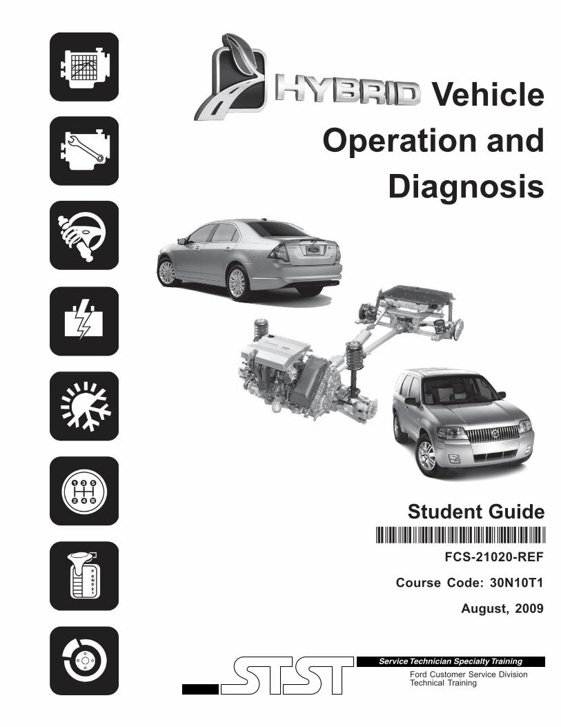
VehicleOperation and
Diagnosis
Student Guide
FCS-21020-REF
Course Code: 30N10T1
August, 2009
fcs-21020-REF

Blank
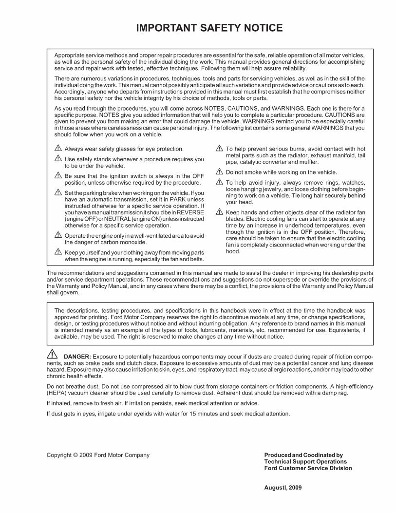
IMPORTANT SAFETY NOTICE
Appropriate service methods and proper repair procedures are essential for the safe, reliable operation of all motor vehicles,as well as the personal safety of the individual doing the work. This manual provides general directions for accomplishingservice and repair work with tested, effective techniques. Following them will help assure reliability.
There are numerous variations in procedures, techniques, tools and parts for servicing vehicles, as well as in the skill of theindividual doing the work. This manual cannot possibly anticipate all such variations and provide advice or cautions as to each.Accordingly, anyone who departs from instructions provided in this manual must first establish that he compromises neitherhis personal safety nor the vehicle integrity by his choice of methods, tools or parts.
As you read through the procedures, you will come across NOTES, CAUTIONS, and WARNINGS. Each one is there for aspecific purpose. NOTES give you added information that will help you to complete a particular procedure. CAUTIONS aregiven to prevent you from making an error that could damage the vehicle. WARNINGS remind you to be especially carefulin those areas where carelessness can cause personal injury. The following list contains some general WARNINGS that youshould follow when you work on a vehicle.
Always wear safety glasses for eye protection.
Use safety stands whenever a procedure requires youto be under the vehicle.
Be sure that the ignition switch is always in the OFFposition, unless otherwise required by the procedure.
Set the parking brake when working on the vehicle. If youhave an automatic transmission, set it in PARK unlessinstructed otherwise for a specific service operation. Ifyou have a manual transmission it should be in REVERSE(engine OFF) or NEUTRAL (engine ON) unless instructedotherwise for a specific service operation.
Operate the engine only in a well-ventilated area to avoidthe danger of carbon monoxide.
Keep yourself and your clothing away from moving partswhen the engine is running, especially the fan and belts.
To help prevent serious burns, avoid contact with hotmetal parts such as the radiator, exhaust manifold, tailpipe, catalytic converter and muffler.
Do not smoke while working on the vehicle.
To help avoid injury, always remove rings, watches,loose hanging jewelry, and loose clothing before begin-ning to work on a vehicle. Tie long hair securely behindyour head.
Keep hands and other objects clear of the radiator fanblades. Electric cooling fans can start to operate at anytime by an increase in underhood temperatures, eventhough the ignition is in the OFF position. Therefore,care should be taken to ensure that the electric coolingfan is completely disconnected when working under thehood.
The recommendations and suggestions contained in this manual are made to assist the dealer in improving his dealership partsand/or service department operations. These recommendations and suggestions do not supersede or override the provisions ofthe Warranty and Policy Manual, and in any cases where there may be a conflict, the provisions of the Warranty and Policy Manualshall govern.
The descriptions, testing procedures, and specifications in this handbook were in effect at the time the handbook wasapproved for printing. Ford Motor Company reserves the right to discontinue models at any time, or change specifications,design, or testing procedures without notice and without incurring obligation. Any reference to brand names in this manualis intended merely as an example of the types of tools, lubricants, materials, etc. recommended for use. Equivalents, ifavailable, may be used. The right is reserved to make changes at any time without notice.
DANGER: Exposure to potentially hazardous components may occur if dusts are created during repair of friction compo-nents, such as brake pads and clutch discs. Exposure to excessive amounts of dust may be a potential cancer and lung diseasehazard. Exposure may also cause irritation to skin, eyes, and respiratory tract, may cause allergic reactions, and/or may lead to otherchronic health effects.
Do not breathe dust. Do not use compressed air to blow dust from storage containers or friction components. A high-efficiency(HEPA) vacuum cleaner should be used carefully to remove dust. Adherent dust should be removed with a damp rag.
If inhaled, remove to fresh air. If irritation persists, seek medical attention or advice.
If dust gets in eyes, irrigate under eyelids with water for 15 minutes and seek medical attention.
Copyright © 2009 Ford Motor Company Produced and Coodinated byTechnical Support OperationsFord Customer Service Division
Augustl, 2009
CUSTOMER EXPECTATIONSM
Customer Expectations: Service1. Make it convenient to have my vehicle
serviced at your dealership.
2. The Service Advisor should demonstratea genuine concern for my service needs.
3. Fix it right the first time, on time.
4. Complete servicing my vehicle in atimely and professional manner.
5. Provide me with a clear and thoroughexplanation of the service performed.
6. Call me within a reasonable amount oftime after my service visit to ensure thatI'm completely satisfied.
7. Be responsive to questions or concernsthat I bring to your attention.
Expectation #3“Fix It Right the First Time, on Time.”Both service advisors and technicians are important players when it comes to Expectation #3.
WhyCustomers tell us “Fixing It Right the First Time, on Time” is one of the reasons they woulddecide to return to a dealer to buy a vehicle and get their vehicles serviced.
Technician TrainingIt is our goal to help the technician acquire all of the skills and knowledge necessary to“Fix it Right the First Time, on Time.” We refer to this as “competency.”
Technician’s RoleAcquire the skills and knowledge for competency in your specialty via:
STST New Model— Web-Based — Web-Based— Instructor Led — Instructor Led
The BenefitsThe successful implementation of expectations means:
— Satisfied customers— Repeat vehicle sales— Repeat service sales— Recognition that Ford and Lincoln/Mercury technicians are “the Best in the Business”
HYBRID VEHICLE OPERATION AND DIAGNOSIS TABLE OF CONTENTS
Hybrid Vehicle Operation and Diagnosis TOC - i August, 2009
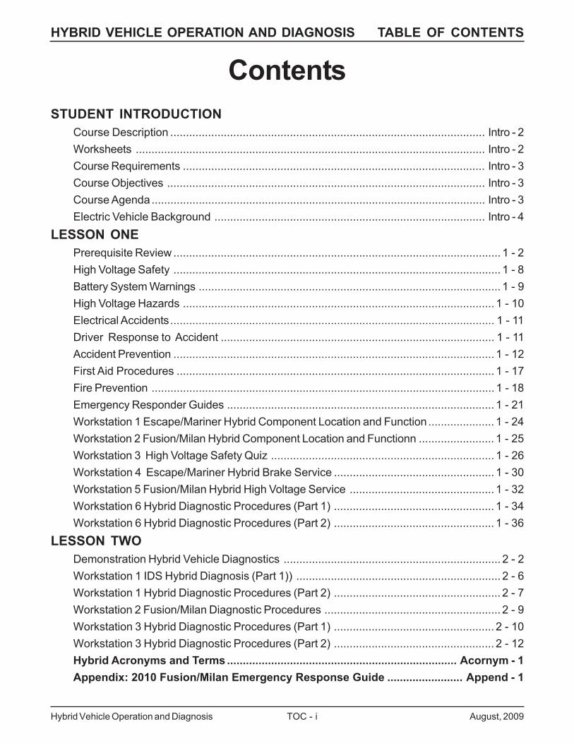
ContentsSTUDENT INTRODUCTION
Course Description .................................................................................................... Intro - 2Worksheets ............................................................................................................... Intro - 2Course Requirements ................................................................................................ Intro - 3Course Objectives ..................................................................................................... Intro - 3Course Agenda.......................................................................................................... Intro - 3Electric Vehicle Background ...................................................................................... Intro - 4
LESSON ONEPrerequisite Review ........................................................................................................ 1 - 2High Voltage Safety ........................................................................................................ 1 - 8Battery System Warnings ................................................................................................ 1 - 9High Voltage Hazards ................................................................................................... 1 - 10Electrical Accidents....................................................................................................... 1 - 11Driver Response to Accident ....................................................................................... 1 - 11Accident Prevention ...................................................................................................... 1 - 12First Aid Procedures ..................................................................................................... 1 - 17Fire Prevention ............................................................................................................. 1 - 18Emergency Responder Guides ..................................................................................... 1 - 21Workstation 1 Escape/Mariner Hybrid Component Location and Function ..................... 1 - 24Workstation 2 Fusion/Milan Hybrid Component Location and Functionn ........................ 1 - 25Workstation 3 High Voltage Safety Quiz ....................................................................... 1 - 26Workstation 4 Escape/Mariner Hybrid Brake Service ................................................... 1 - 30Workstation 5 Fusion/Milan Hybrid High Voltage Service .............................................. 1 - 32Workstation 6 Hybrid Diagnostic Procedures (Part 1) ................................................... 1 - 34Workstation 6 Hybrid Diagnostic Procedures (Part 2) ................................................... 1 - 36
LESSON TWODemonstration Hybrid Vehicle Diagnostics ..................................................................... 2 - 2Workstation 1 IDS Hybrid Diagnosis (Part 1)) ................................................................. 2 - 6Workstation 1 Hybrid Diagnostic Procedures (Part 2) ..................................................... 2 - 7Workstation 2 Fusion/Milan Diagnostic Procedures ........................................................ 2 - 9Workstation 3 Hybrid Diagnostic Procedures (Part 1) ................................................... 2 - 10Workstation 3 Hybrid Diagnostic Procedures (Part 2) ................................................... 2 - 12Hybrid Acronyms and Terms ......................................................................... Acornym - 1Appendix: 2010 Fusion/Milan Emergency Response Guide ........................ Append - 1

HYBRID VEHICLE OPERATION AND DIAGNOSIS TABLE OF CONTENTS
Hybrid Vehicle Operation and Diagnosis TOC - ii August, 2009

HYBRID VEHICLE OPERATION AND DIAGNOSIS INTRODUCTION
August, 2009 Intro - 1 Hybrid Vehicle Operation and Diagnosis
INTRODUCTION
HYBRID VEHICLE OPERATION AND DIAGNOSIS INTRODUCTION
Hybrid Vehicle Operation and Diagnosis Intro - 2 August, 2009
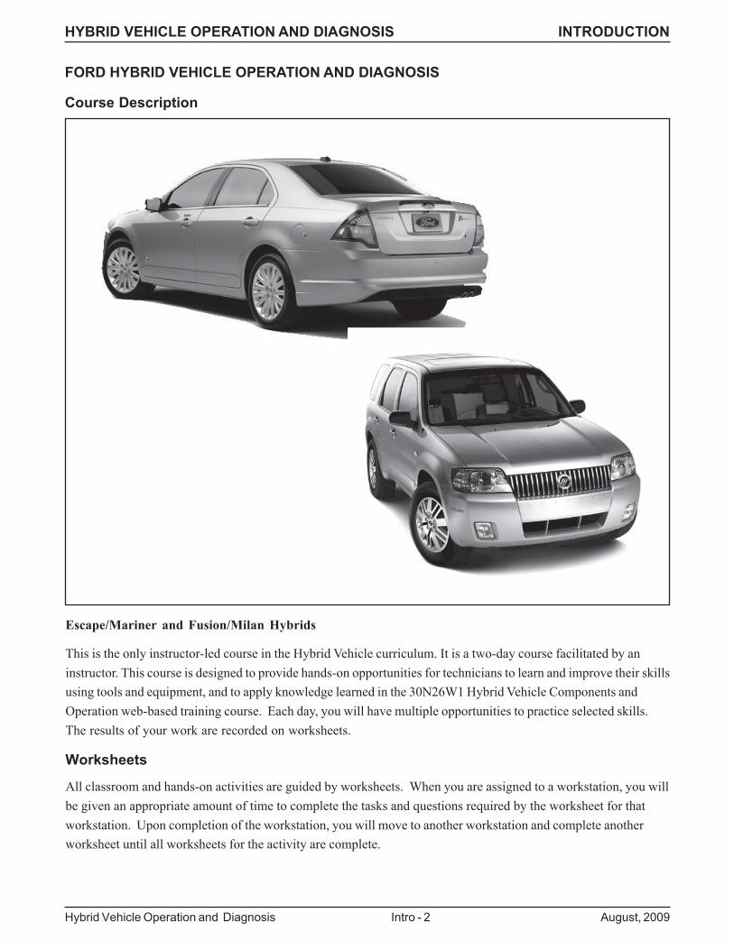
This is the only instructor-led course in the Hybrid Vehicle curriculum. It is a two-day course facilitated by aninstructor. This course is designed to provide hands-on opportunities for technicians to learn and improve their skillsusing tools and equipment, and to apply knowledge learned in the 30N26W1 Hybrid Vehicle Components andOperation web-based training course. Each day, you will have multiple opportunities to practice selected skills.The results of your work are recorded on worksheets.
Worksheets
All classroom and hands-on activities are guided by worksheets. When you are assigned to a workstation, you willbe given an appropriate amount of time to complete the tasks and questions required by the worksheet for thatworkstation. Upon completion of the workstation, you will move to another workstation and complete anotherworksheet until all worksheets for the activity are complete.
FORD HYBRID VEHICLE OPERATION AND DIAGNOSIS
Course Description
Escape/Mariner and Fusion/Milan Hybrids
HYBRID VEHICLE OPERATION AND DIAGNOSIS INTRODUCTION
August, 2009 Intro - 3 Hybrid Vehicle Operation and Diagnosis
Course Requirements
Each technician attending this course will be required to pass a combination of hands-on and written evaluations.These will be administered on the afternoon of the 2nd day.
The hands-on evaluation is a pass/fail type. It will be conducted with exercises in hybrid vehicle performancediagnosis, and will cover:
– hybrid performance system diagnosis
– service publication navigation
– selected special tool usage
In order to pass the course, you must demonstrate mastery of the skills covered at the evaluated hands-on exerciseAND you must answer at least 80% of the written post-test questions correctly.
Course Objectives
Upon successful completion of this course, you will be able to:
Describe Ford and Lincoln-Mercury Hybrid Vehicle Components and Operation
Describe unique hybrid vehicle safety procedures
Perform visual inspections and selected tests on various hybrid vehicle components
Diagnose hybrid vehicle performance concerns
Perform tests to verify hybrid vehicle concerns and identify causes of these concerns
Perform hybrid vehicle service procedures
.
Course Agenda
LESSON ONE:
Introductions, Safety Briefing, Prerequisite Review, Lesson 1 Workstations
LESSON TWO
Lesson 2 Workstation Reviews, Lesson 2 Workstations, Final Review, Post-Test
HYBRID VEHICLE OPERATION AND DIAGNOSIS INTRODUCTION
Hybrid Vehicle Operation and Diagnosis Intro - 4 August, 2009
ELECTRIC VEHICLE BACKGROUND
The concept of an electric vehicle is not new. In fact, Henry Ford’s wife Clara used a 1914 Detroit Electric Model47 Brougham to travel around Dearborn, visiting her friend, Mrs. Mina Ives and sister, Mrs. Eva Brubaker. Thiscar resided at the Ford’s Fair Lane Estate from 1916 until the 1930’s.
Early automotive pioneers began developing electric vehicles during the Nineteenth Century. However, it soonbecame apparent that electrical energy storage on a vehicle would be difficult. Batteries are heavy and require agreat deal of room. Because of this, and the promise of the internal combustion engine, early automakers soonabandoned electric power.
But petroleum fuels have a drawback, they generate exhaust emissions. While this was not a concern for earlyautomakers, it has become a major concern for auto manufacturers today.
Ford Motor Company began its electric vehicle (EV) development in 1982 with the introduction of the ETX 1, aconverted Lynx LN7. This experimental vehicle was powered by a lead-acid battery and a50-horsepower AC motor. The ETX 1 was followed by the ETX 2, a converted Aerostar using a refined 70-horsepower motor. The ETX 2 tested various battery types.
In 1993, Ford began a demonstration program to help potential customers gain real-world experience in the use ofelectric-powered vehicles. With the participation of utility companies and other commercial organizations, thisprogram is now nearing the 1-million mile mark in vehicle miles driven. The vehicle platform for this demonstrationwas the Ecostar , a two-passenger electric vehicle based on the European Ford Escort Van..
In 1998 the introduction of the electrically powered Ranger introduced the next generation of electric vehicles. TheFord EV demonstration program served as a test bed for electric powered vehicles..
However, battery technology again handicapped the development of the pure electric vehicle. The limited range,and weight of the batteries required to achieve that range was too great, and in 2001 production of the EV Rangerwas discontinued.
But Ford did not stop developing electric technology, it was only redirected towards a system that would combinethe internal combustion engine and the electric motor to provide out customers with improved fuel economy andrange, while dramatically lowering vehicle emissions.
This effort resulted in the introduction of the 2005 Escape/Mariner Hybrid, the first SUV to feature an gasoline-electric powertrain.
For 2010 Ford is introducing the Fusion/Milan Hybrid. This next generation hybrid utilizes the latest technology tocreate a practical vehicle with the comfort, range, lower emissions, fuel economy and durability Ford and Lincoln-Mercury customers have come to expect.
Both the Escape/Mariner and Fusion/Milan Hybrids represent the highest standards in technology and quality, butbe assured that Ford will continue the research and development needed to create high-quality, fuel-efficient hybridand electric vehicles to meet the transportation needs of our customers today, and in the future!

LESSON ONE PREREQUISITE REVIEW
August, 2009 1 - 1 Hybrid Vehicle Operation and Diagnosis
LESSON ONE
LESSON ONE PREREQUISITE REVIEW
Hybrid Vehicle Operation and Diagnosis 1 - 2 August, 2009
PREREQUISITE REVIEW
DIRECTIONS: Answer the following hybrid vehicle questions. These will be reviewed in class.
1. What components are cooled by the M/E cooling system?
_______________________________________________________________________________________
_______________________________________________________________________________________
_______________________________________________________________________________________
_______________________________________________________________________________________
_______________________________________________________________________________________
2. What internal engine components are unique on the Hybrid gasoline engine, and why?
_______________________________________________________________________________________
_______________________________________________________________________________________
3. What is the function of the DC/AC inverter?
A. To reduce HV battery voltage to charge the low voltage battery.
B. To convert 12 volt DC voltage to 110 AC voltage.
C. To convert 330 or 275 DC voltage (vehicle dependant) to 110 AC voltage.
D. There is no DC/AC inverter on hybrid vehicles.
4. What type of cooling system does the Fusion/Milan use to cool the HV battery?
A. Cabin air drawn into the battery compartment by a fan.
B. An AUX A/C system that is connected to the air conditioning system.
C. An independent A/C system that is driven by the gasoline engine.
D. A fan that draws outside air into the battery compartment.

LESSON ONE PREREQUISITE REVIEW
August, 2009 1 - 3 Hybrid Vehicle Operation and Diagnosis
5. Where is the HV fuse located on both the Escape/Mariner and Fusion Milan?
_______________________________________________________________________________________
_______________________________________________________________________________________
_______________________________________________________________________________________
_______________________________________________________________________________________
_______________________________________________________________________________________
6. Which of the functions listed below is performed by the shift cable?
A. Engages the eCVT in Drive.
B. Engages the eCVT in Reverse.
C. Engages the parking pawl.
D. All of the above.
7. Which components are part of the hybrid vehicle high voltage system?
_______________________________________________________________________________________
_______________________________________________________________________________________
_______________________________________________________________________________________
_______________________________________________________________________________________
_______________________________________________________________________________________
8. What measures were taken in the design of hybrid vehicles to prevent current leakage from the HV battery?
_______________________________________________________________________________________
_______________________________________________________________________________________
_______________________________________________________________________________________
LESSON ONE PREREQUISITE REVIEW
Hybrid Vehicle Operation and Diagnosis 1 - 4 August, 2009
9. What type of EPAS systems can be found on hybrid vehicles?
A. Remote PSCM rack-type system
B. Column mounted EPAS system
C. Rack mounted PSCM EPAS system
D. All of the above.
10. What is the purpose of the regenerative braking system?
_______________________________________________________________________________________
_______________________________________________________________________________________
11. What unique information is displayed on the hybrid vehicle tachometer?
_______________________________________________________________________________________
_______________________________________________________________________________________
12. Where is the gasoline engine starter motor located on a hybrid vehicle?
A. At the rear of the engine lower right side
B. It is integrated into the FEAD system
C. Near the front left side of the engine
D. None of the above.
13. What control module adjusts the contributions of the gasoline engine, the traction motor and generator duringhybrid operation?
A. PCM
B. TCM
C. BCM
D. PSCM
14. The A/C compressor on a 2008 Escape/Mariner hybrid vehicle is _________________ (select the bestanswer from the list below)
A. Driven by the FEAD of the gasoline engine
B. A swashplate type pump
C. Electrically driven
D. A scroll type pump
LESSON ONE PREREQUISITE REVIEW
August, 2009 1 - 5 Hybrid Vehicle Operation and Diagnosis
15. What is the function of the high voltage interlock?
A. To prevent the vehicle from being started in any gear but Park of Neutral..
B. To disable the high voltage system if any HV connectors are disconnected.
C. To prevent the vehicle from being placed into gear without the brake pedal being depressed.
D. All of the above
16. What is the service interval for the air cleaner on the 2010 Fusion/Milan?
_______________________________________________________________________________________
_______________________________________________________________________________________
17. When the service disconnect switch is removed from a Fusion/Milan Hybrid vehicle, which of the followingcomponents will still have high-voltage current running to them (select all that apply)?
A. The BPSM
B. The BECM
C. The DC/DC Converter
D. The High-Voltage Low-Current Fuse
18. What system provides power to the A/C compressor on the Fusion/Milan Hybrid?
A. The high-voltage high-current system
B. The 12-volt system
C. The high-voltage low-current system
D. The gasoline engine
19. What component on the Fusion/Milan hybrid performs the same function as the inertia switch on the Escape/Mariner Hybrid?
_______________________________________________________________________________________
_______________________________________________________________________________________
20. A customer needs information on the operation of the instrument cluster in their 2010 Fusion. Where can youdirect them to get an interactive tutorial for the operation if the IC?
_______________________________________________________________________________________
_______________________________________________________________________________________
LESSON ONE PREREQUISITE REVIEW
Hybrid Vehicle Operation and Diagnosis 1 - 6 August, 2009
21. What type of conventional brake system is used on 2009 MY and later Escape/Mariner and 2010 Fusion MilanHybrids?
A. Simulation Brake Activation system
B. Electronic Hydraulic Brake system
C. Hydro Max
D. EPAS Boost Brake Activation system
22. What type of conventional brake system is used on 2005 - 2008 Escape/Mariner Hybrids?
A. Simulation Brake Activation system
B. Electronic Hydraulic Brake system
C. Hydro Max
D. EPAS Boost Brake Activation system

LESSON ONE HIGH VOLTAGE SAFETY
August, 2009 1 - 7 Hybrid Vehicle Operation and Diagnosis
HIGH VOLTAGESAFETY

LESSON ONE HIGH VOLTAGE SAFETY
Hybrid Vehicle Operation and Diagnosis 1 - 8 August, 2009
Ford and Lincoln-Mercury hybrid vehicles have been designed with maximum driver and service technician safetyin mind. There are multiple devices that are incorporated in the vehicle to minimize any danger from electricshock.
However, in order to ensure your safety whenever working around either the Escape/Mariner or Fusion/MilanHybrids, there are some critical safety steps that you must perform. This lesson will describe these steps, as wellas provide you with other important information that you must know when working around high voltage.
HIGH VOLTAGE SAFETY
LESSON ONE HIGH VOLTAGE SAFETY
August, 2009 1 - 9 Hybrid Vehicle Operation and Diagnosis
BATTERY SYSTEM WARNINGS
WARNING: BATTERIES NORMALLY PRODUCE EXPLOSIVE GASES WHICH CANCAUSE PERSONAL INJURY OR DEATH. DO NOT ALLOW FLAMES, SPARKS ORLIGHTED SUBSTANCES TO COME NEAR THE BATTERIES. WHEN CHARGING ORWORKING NEAR THE BATTERIES, ALWAYS SHIELD YOUR FACE AND PROTECT YOUREYES. ALWAYS PROVIDE VENTILATION.
WARNING: NICKEL-METAL HYDRIDE BATTERIES CONTAIN POTASSIUMHYDROXIDE. AVOID CONTACT WITH SKIN, EYES, RESPIRATORY SYSTEM, ORCLOTHING. ALSO, SHIELD YOUR FACE WHEN WORKING NEAR BATTERIES TOPROTECT AGAINST POSSIBLE DUST OR MIST. IF CHEMICAL HAS SOAKED INTO ORTHROUGH CLOTHING, REMOVE CLOTHING IMMEDIATELY. IN CASE OF CONTACTWITH THE SKIN OR EYES, FLUSH IMMEDIATELY WITH WATER FOR A MINIMUM OFFIFTEEN MINUTES AND SEEK PROMPT MEDICAL ATTENTION. IF CHEMICAL HASBEEN INHALED, MOVE TO FRESH AIR AND SEEK PROMPT MEDICAL ATTENTION. IFCHEMICAL IS SWALLOWED, SEEK IMMEDIATE MEDICAL ATTENTION.
WARNING: HIGH VOLTAGE COMPONENT REPAIR SHOULD ONLY BE CARRIED OUTBY TRAINED PERSONNEL. INCORRECTLY CARRYING OUT REPAIR PROCEDURESMAY RESULT IN INJURY OR DEATH. ALL HIGH VOLTAGE COMPONENTS ON THISVEHICLE ARE MARKED WITH THE FOLLOWING WARNING LABEL.
LESSON ONE HIGH VOLTAGE SAFETY
Hybrid Vehicle Operation and Diagnosis 1 - 10 August, 2009
HIGH VOLTAGE HAZARDS
This portion of the course will examine the three hazards associated with high voltage. Later we’ll discuss how toavoid mistakes that can lead to electrical accidents. The three high voltage hazards are shock, arcing and blast.
Hazard One: Electric Shock
People are affected by electric shock in three ways:
• Muscle Contraction – a 10 mA, 60 hertz current can cause muscles to contract. A hand exposed to sufficientelectrical current is unable to release its grip. Chest muscles paralyze and respiration ceases if sufficient currentpasses through the chest.
• Fibrillation – fibrillation is the disruption of a body’s normal heart beat. The heart beats because the brain sendsit an electrical signal to do so. Sixty (60) volts is enough to interrupt the electrical signal from the brain andcause the heart to stop pumping. The current must follow a path through the body (hand-to-hand, etc.) in orderfor fibrillation to occur.
• Tissue Damage – tissues within the body and at the current exit point can be damaged by electrical shock whenthe current exceeds 5 amps. Damage to tissue is caused by heat generated from the current flow. If the energydelivered by the electrical shock is high, the heat cannot be dissipated and body tissue is burned.
Susceptibility to electric shock varies from person to person, depending on their physical attributes (skin thickness,etc.). An open cut can reduce a person’s natural resistance, and moist skin will increase the chances of anelectric shock taking place. Even a relatively small electric shock can cause serious injury. A person’s involuntarymuscle reaction to a current as low as 3 mA can result in bruises, bone fractures and possible death caused by acollision or fall.
Hazard Two: Arcing
An arc is a discharge of electricity across a circuit gap. The primary danger of this hazard is the burn that a personcan receive. The heat at each end of an arc reaches up to and beyond 35,000°F, or about four times the surfacetemperature of the sun. Arcing is a significant concern in power plants and other areas of extremely high voltagebecause arc size and length are proportionate to voltage. Arcing is a potential hazard with lower voltages as well,and can result in insulation damage, melting of conductors, and the vaporization of metal.
Hazard Three: Blast
Electric blast is the pressure expansion caused by an arc. The expansion is actually the rapid heating of thesurrounding air and the boiling of a metal, usually copper. Both expand at incredible proportions under the intenseheat of an arc. Copper expands by a factor of 67,000 when vaporized.
LESSON ONE HIGH VOLTAGE SAFETY
August, 2009 1 - 11 Hybrid Vehicle Operation and Diagnosis
ELECTRICAL ACCIDENTS
Electrical accidents can usually be attributed to one or more of the following causes:
• Unsafe Equipment or Installation – serious problems can occur when using improper equipment. Not only mustequipment have a safe design, but it must be installed correctly.
• Unsafe Work Areas – poor lighting, moisture, flammable liquids, flammable gases, poor labeling, and coveredlabels are all items of concern around high voltage.
• Unsafe Acts by Workers – failure to follow established procedures can result in an electrical accident.
Personal injury from electricity can vary from trivial burns to complete charring of the skin. Approximately 4000people in the United States are injured by electricity each year, and about 1000 are accidently electrocuted. Fivepercent of admissions to burn centers are related to electrical injury.
Whether or not an electric shock will cause injury or death is influenced by the amount, duration, and pathway ofthe current. A relatively large amount of electrical energy may be harmless due to its inability to penetrate dry,calloused skin. A shock victim can be thrown back, or become paralyzed and remain in contact with the circuit. Ineither case, extreme care should be taken when treating a person affected by electricity. Symptoms of electricshock are loss of consciousness and skin burns.
If possible, carry out the following steps in the event of a collision, fire or some other emergency situation. However,never endanger yourself or others who are near the vehicle.
1. Stop and put the gear selector in the Park (P) position.
2. Turn the ignition switch to the OFF position and remove the key.
3. Set the parking brake.
4. Exit the vehicle.
5. Contact crash/fire/rescue emergency personnel and inform them of the type of vehicle (Hybrid) and the nature ofthe emergency
If possible, carry out the following steps in the eventof a collision, fire or some other emergencysituation. However, never endanger yourself orothers who are near the vehicle.
DRIVER RESPONSE TO ACCIDENT
LESSON ONE HIGH VOLTAGE SAFETY
Hybrid Vehicle Operation and Diagnosis 1 - 12 August, 2009
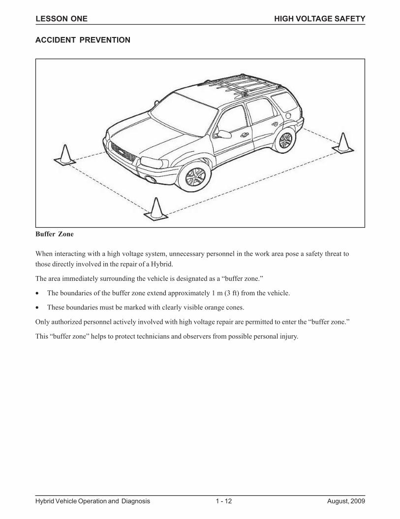
When interacting with a high voltage system, unnecessary personnel in the work area pose a safety threat tothose directly involved in the repair of a Hybrid.
The area immediately surrounding the vehicle is designated as a “buffer zone.”
• The boundaries of the buffer zone extend approximately 1 m (3 ft) from the vehicle.
• These boundaries must be marked with clearly visible orange cones.
Only authorized personnel actively involved with high voltage repair are permitted to enter the “buffer zone.”
This “buffer zone” helps to protect technicians and observers from possible personal injury.
ACCIDENT PREVENTION
Buffer Zone
LESSON ONE HIGH VOLTAGE SAFETY
August, 2009 1 - 13 Hybrid Vehicle Operation and Diagnosis
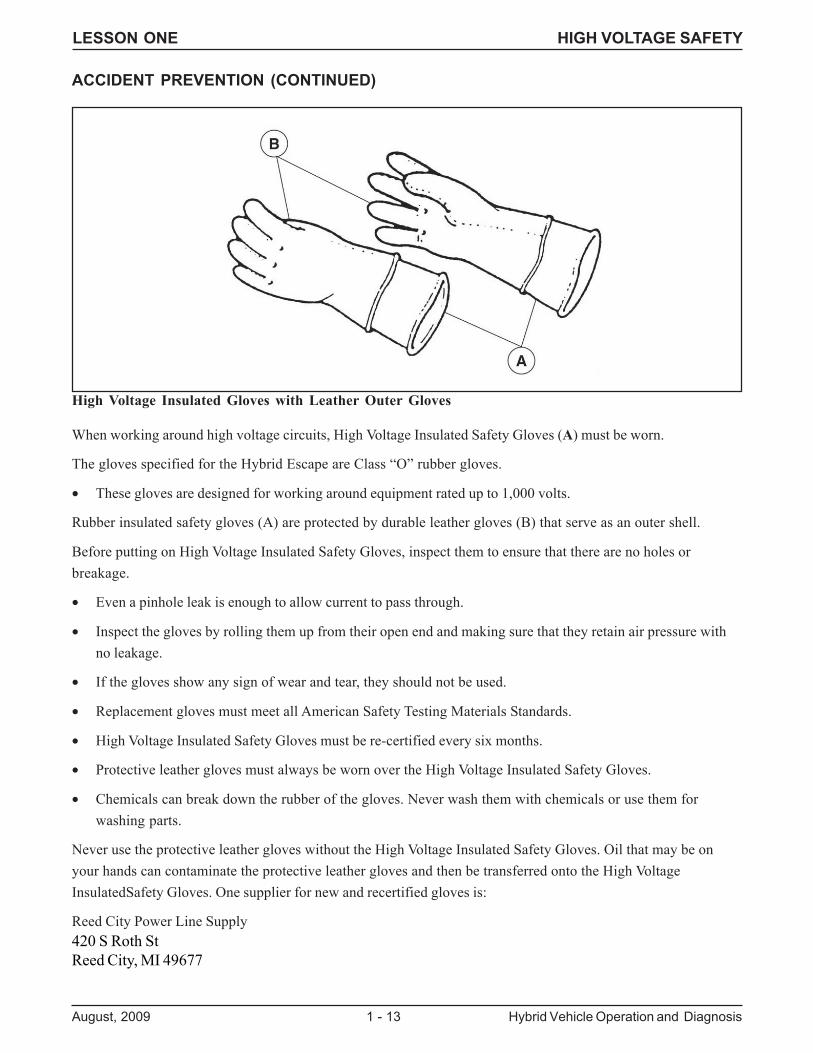
When working around high voltage circuits, High Voltage Insulated Safety Gloves (A) must be worn.
The gloves specified for the Hybrid Escape are Class “O” rubber gloves.
• These gloves are designed for working around equipment rated up to 1,000 volts.
Rubber insulated safety gloves (A) are protected by durable leather gloves (B) that serve as an outer shell.
Before putting on High Voltage Insulated Safety Gloves, inspect them to ensure that there are no holes orbreakage.
• Even a pinhole leak is enough to allow current to pass through.
• Inspect the gloves by rolling them up from their open end and making sure that they retain air pressure withno leakage.
• If the gloves show any sign of wear and tear, they should not be used.
• Replacement gloves must meet all American Safety Testing Materials Standards.
• High Voltage Insulated Safety Gloves must be re-certified every six months.
• Protective leather gloves must always be worn over the High Voltage Insulated Safety Gloves.
• Chemicals can break down the rubber of the gloves. Never wash them with chemicals or use them forwashing parts.
Never use the protective leather gloves without the High Voltage Insulated Safety Gloves. Oil that may be onyour hands can contaminate the protective leather gloves and then be transferred onto the High VoltageInsulatedSafety Gloves. One supplier for new and recertified gloves is:
Reed City Power Line Supply420 S Roth StReed City, MI 49677
ACCIDENT PREVENTION (CONTINUED)
High Voltage Insulated Gloves with Leather Outer Gloves
LESSON ONE HIGH VOLTAGE SAFETY
Hybrid Vehicle Operation and Diagnosis 1 - 14 August, 2009
ACCIDENT PREVENTION (CONTINUED)
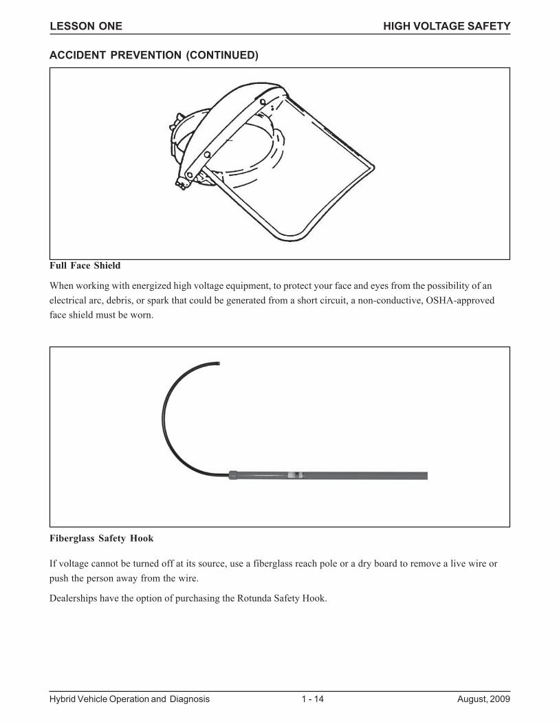
Full Face Shield
Fiberglass Safety Hook
When working with energized high voltage equipment, to protect your face and eyes from the possibility of anelectrical arc, debris, or spark that could be generated from a short circuit, a non-conductive, OSHA-approvedface shield must be worn.
If voltage cannot be turned off at its source, use a fiberglass reach pole or a dry board to remove a live wire orpush the person away from the wire.
Dealerships have the option of purchasing the Rotunda Safety Hook.
LESSON ONE HIGH VOLTAGE SAFETY
August, 2009 1 - 15 Hybrid Vehicle Operation and Diagnosis
Hybrid Electric Vehicles (HEV) operate on a system that is isolated from earth ground, and its high voltage systemis isolated from the vehicle chassis ground. A person must join the positive and the negative to become part of thehigh voltage circuit. As with any high voltage system, assume nothing when working around an HEV.
Safe practices will protect you and those around you. In fact, most HEV guidelines are the same as those used inhome electrical repairs.Keep in mind the following safety rules and share them with others:
1. Do not work when you are tired or taking medicine that makes you drowsy.
2. Do not work under poor light.
3. Do not work in damp areas.
4. Use approved tools, equipment, and protective devices.
5. Do not work if you or your clothes are wet.
6. Remove all rings, bracelets, and metallic items.
7. Never assume that a circuit is open. Check it with a device or piece of equipment that you are sure isoperating correctly.
8. Do not tamper with safety devices. Never defeat an interlock switch. Verify that all interlocks operatecorrectly.
9. Keep your tools and equipment in good condition. Use the correct tool for the job.
10. Verify that capacitors have discharged.
11. Do not remove equipment grounds. Verify that all grounds are intact.
12. Do not use adapters that defeat ground connections.
13. Use only an approved fire extinguisher. Water can conduct electrical current and increase the hazardsand damage. Carbon dioxide (CO2) gas extinguishers are preferred for most electrical fires.
14. Follow directions when using solvents and other chemicals. Some may explode, ignite, or damageelectrical circuits.
15. Certain electronic components affect the safe performance of equipment. Always use the correctreplacement parts.
16. Do not attempt to work on complex equipment or circuits before you’re fully trained. There may behidden dangers.
17. Some of the best safety information for electrical and electric equipment is in the literature prepared bythe manufacturer. Find and use it.
18. Always wear protective eyewear.
ACCIDENT PREVENTION (CONTINUED)
LESSON ONE HIGH VOLTAGE SAFETY
Hybrid Vehicle Operation and Diagnosis 1 - 16 August, 2009
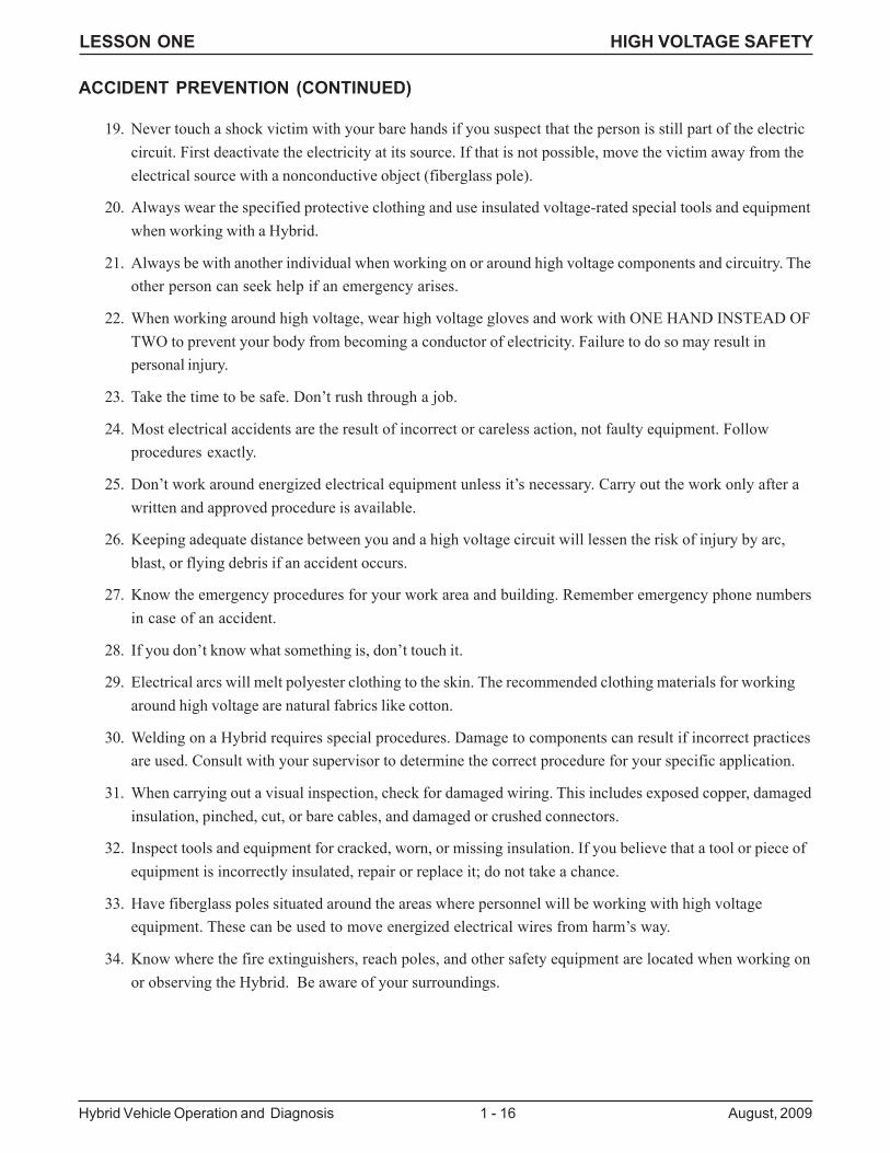
19. Never touch a shock victim with your bare hands if you suspect that the person is still part of the electriccircuit. First deactivate the electricity at its source. If that is not possible, move the victim away from theelectrical source with a nonconductive object (fiberglass pole).
20. Always wear the specified protective clothing and use insulated voltage-rated special tools and equipmentwhen working with a Hybrid.
21. Always be with another individual when working on or around high voltage components and circuitry. Theother person can seek help if an emergency arises.
22. When working around high voltage, wear high voltage gloves and work with ONE HAND INSTEAD OFTWO to prevent your body from becoming a conductor of electricity. Failure to do so may result inpersonal injury.
23. Take the time to be safe. Don’t rush through a job.
24. Most electrical accidents are the result of incorrect or careless action, not faulty equipment. Followprocedures exactly.
25. Don’t work around energized electrical equipment unless it’s necessary. Carry out the work only after awritten and approved procedure is available.
26. Keeping adequate distance between you and a high voltage circuit will lessen the risk of injury by arc,blast, or flying debris if an accident occurs.
27. Know the emergency procedures for your work area and building. Remember emergency phone numbersin case of an accident.
28. If you don’t know what something is, don’t touch it.
29. Electrical arcs will melt polyester clothing to the skin. The recommended clothing materials for workingaround high voltage are natural fabrics like cotton.
30. Welding on a Hybrid requires special procedures. Damage to components can result if incorrect practicesare used. Consult with your supervisor to determine the correct procedure for your specific application.
31. When carrying out a visual inspection, check for damaged wiring. This includes exposed copper, damagedinsulation, pinched, cut, or bare cables, and damaged or crushed connectors.
32. Inspect tools and equipment for cracked, worn, or missing insulation. If you believe that a tool or piece ofequipment is incorrectly insulated, repair or replace it; do not take a chance.
33. Have fiberglass poles situated around the areas where personnel will be working with high voltageequipment. These can be used to move energized electrical wires from harm’s way.
34. Know where the fire extinguishers, reach poles, and other safety equipment are located when working onor observing the Hybrid. Be aware of your surroundings.
ACCIDENT PREVENTION (CONTINUED)
LESSON ONE HIGH VOLTAGE SAFETY
August, 2009 1 - 17 Hybrid Vehicle Operation and Diagnosis
FIRST AID PROCEDURES
First Aid for Electric Shock
The longer a person remains in contact with an electrical current, the less chance he or she has for survival. Thevictim’s breathing may stop, and his or her body may appear stiff.
1. CALL FOR HELP from other personnel in your area. Then attempt to break the electrical connection asquickly as possible without exposing yourself to the current.
2. If the current cannot be turned off, use a fiberglass reach pole to remove the wire or push the person awayfrom it. Stand on a dry surface while doing this. Do not touch the person or wire with your bare hands untilthe electrical connection is broken.
3. Summon medical aid.
4. If the person has stopped breathing or his heart has stopped pumping, begin CPR procedures and continueuntil help arrives.
5. If the person must be moved, take proper precautions. Be sure to immobilize injured parts. Pull the personlengthwise (never sideways). If possible, use a stretcher or cot.
Cardio-Pulmonary Resuscitation (CPR)
If a person has received an electric shock, it may be necessary to administer CPR. The goal of CPR is to provideoxygen to the brain, heart and other vital organs until medical help arrives.
When to Use CPR
CPR should only be administered by a trained individual. Determining the condition of the person is an importantstep in assessing cardiac and breathing functions to determine if CPR is necessary.
Unless it is absolutely necessary, do not move the victim if trauma to the head or neck has been sustained.Emergency personnel properly trained for these types of injuries should be on hand to administer aid to the person.
Where to Get CPR Training
The American Red Cross offers CPR training on a regular basis.
LESSON ONE HIGH VOLTAGE SAFETY
Hybrid Vehicle Operation and Diagnosis 1 - 18 August, 2009
FIRE PREVENTION
General fire precautions should be observed at all times. Shop cleanliness is a good fire preventative. Storagelockers, drawers, and partitions should be made of fire-resistant material. Flammable materials should be kept at asafe distance from heating units and open flames. Flammable liquids should be stored in approved safetycontainers and, when not in use, stored in proper storage areas. Whenever flammable liquids such as cleaningsolvents, kerosene or gasoline are used, the work area should be well-ventilated and all heating units (particularlyopen-flame torches) should be removed from the job site.
Classes of Fire
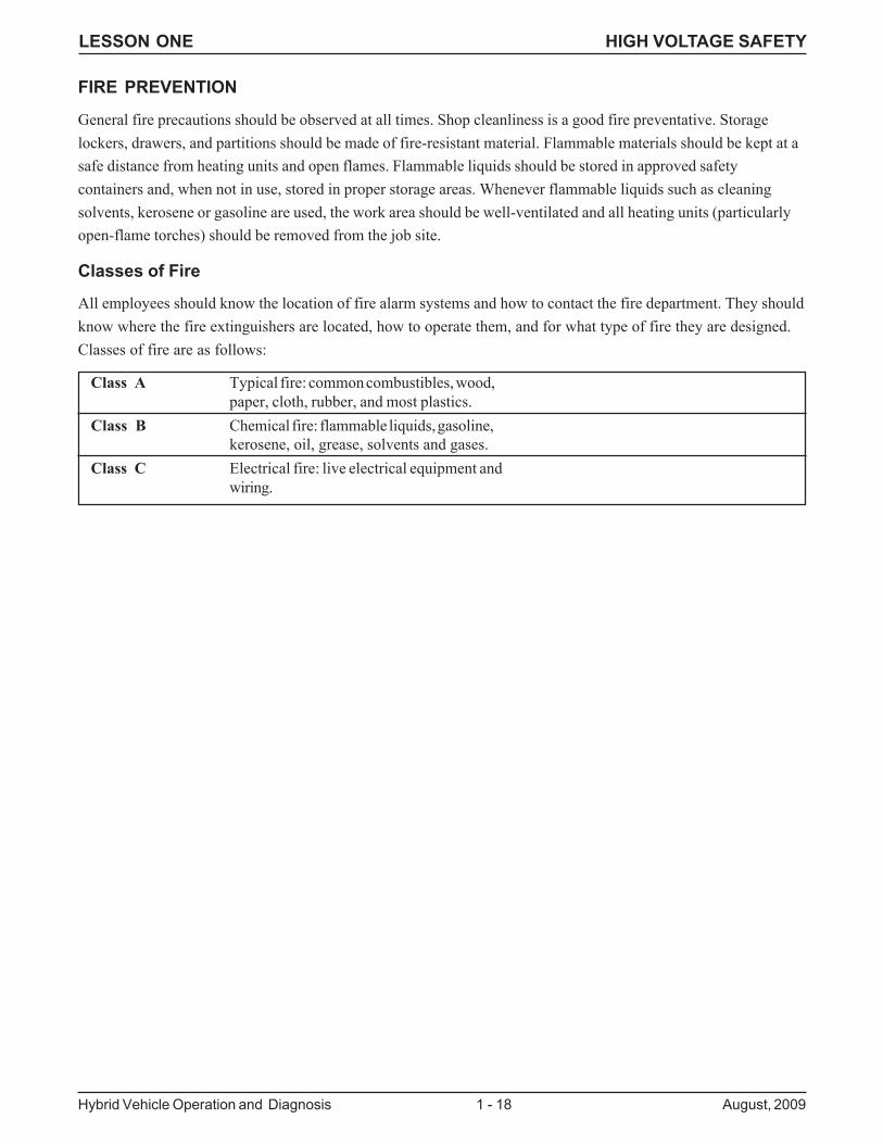
All employees should know the location of fire alarm systems and how to contact the fire department. They shouldknow where the fire extinguishers are located, how to operate them, and for what type of fire they are designed.Classes of fire are as follows:
Class A Typical fire: common combustibles, wood,paper, cloth, rubber, and most plastics.
Class B Chemical fire: flammable liquids, gasoline,kerosene, oil, grease, solvents and gases.
Class C Electrical fire: live electrical equipment andwiring.
LESSON ONE HIGH VOLTAGE SAFETY
August, 2009 1 - 19 Hybrid Vehicle Operation and Diagnosis
Types of Fire Extinguishers
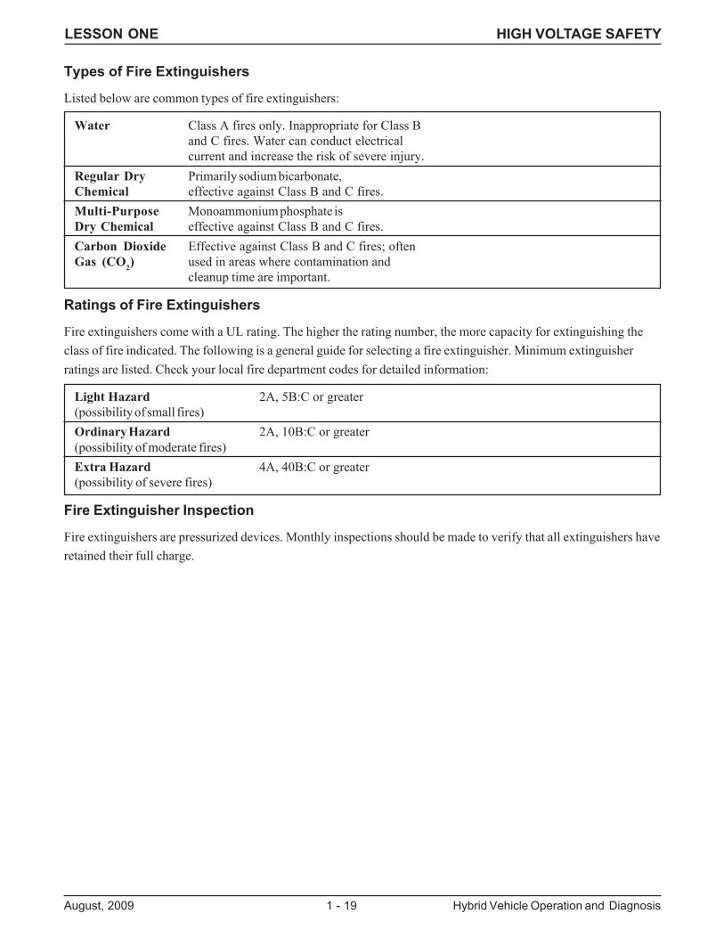
Listed below are common types of fire extinguishers:
Water Class A fires only. Inappropriate for Class Band C fires. Water can conduct electricalcurrent and increase the risk of severe injury.
Regular Dry Primarily sodium bicarbonate,Chemical effective against Class B and C fires.Multi-Purpose Monoammonium phosphate isDry Chemical effective against Class B and C fires.Carbon Dioxide Effective against Class B and C fires; oftenGas (CO2) used in areas where contamination and
cleanup time are important.
Ratings of Fire Extinguishers
Fire extinguishers come with a UL rating. The higher the rating number, the more capacity for extinguishing theclass of fire indicated. The following is a general guide for selecting a fire extinguisher. Minimum extinguisherratings are listed. Check your local fire department codes for detailed information:
Light Hazard 2A, 5B:C or greater(possibility of small fires)Ordinary Hazard 2A, 10B:C or greater(possibility of moderate fires)Extra Hazard 4A, 40B:C or greater(possibility of severe fires)
Fire Extinguisher Inspection
Fire extinguishers are pressurized devices. Monthly inspections should be made to verify that all extinguishers haveretained their full charge.
LESSON ONE HIGH VOLTAGE SAFETY
Hybrid Vehicle Operation and Diagnosis 1 - 20 August, 2009
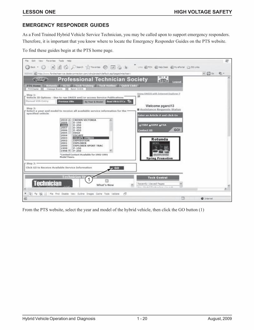
EMERGENCY RESPONDER GUIDES
As a Ford Trained Hybrid Vehicle Service Technician, you may be called upon to support emergency responders.Therefore, it is important that you know where to locate the Emergency Responder Guides on the PTS website.
To find these guides begin at the PTS home page.
From the PTS website, select the year and model of the hybrid vehicle, then click the GO button (1)
1
LESSON ONE HIGH VOLTAGE SAFETY
August, 2009 1 - 21 Hybrid Vehicle Operation and Diagnosis
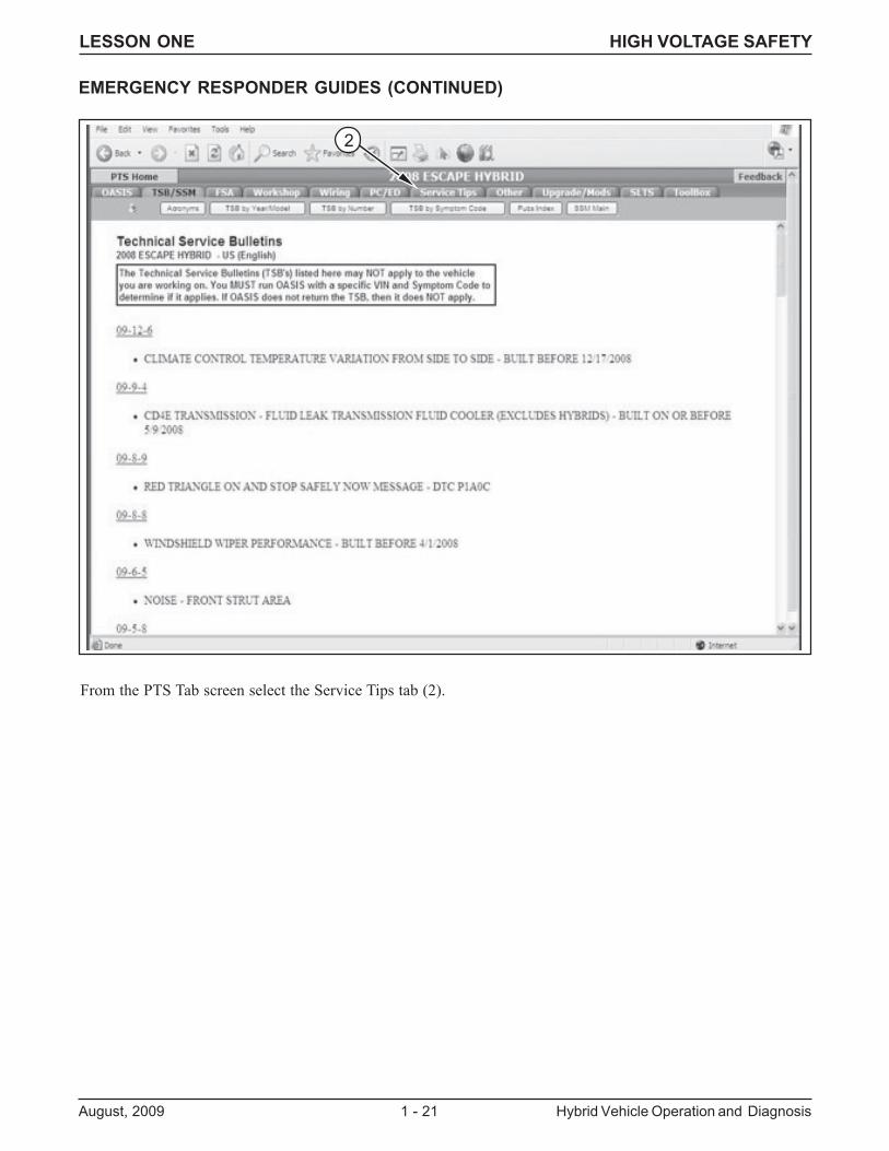
EMERGENCY RESPONDER GUIDES (CONTINUED)
From the PTS Tab screen select the Service Tips tab (2).
2
LESSON ONE HIGH VOLTAGE SAFETY
Hybrid Vehicle Operation and Diagnosis 1 - 22 August, 2009
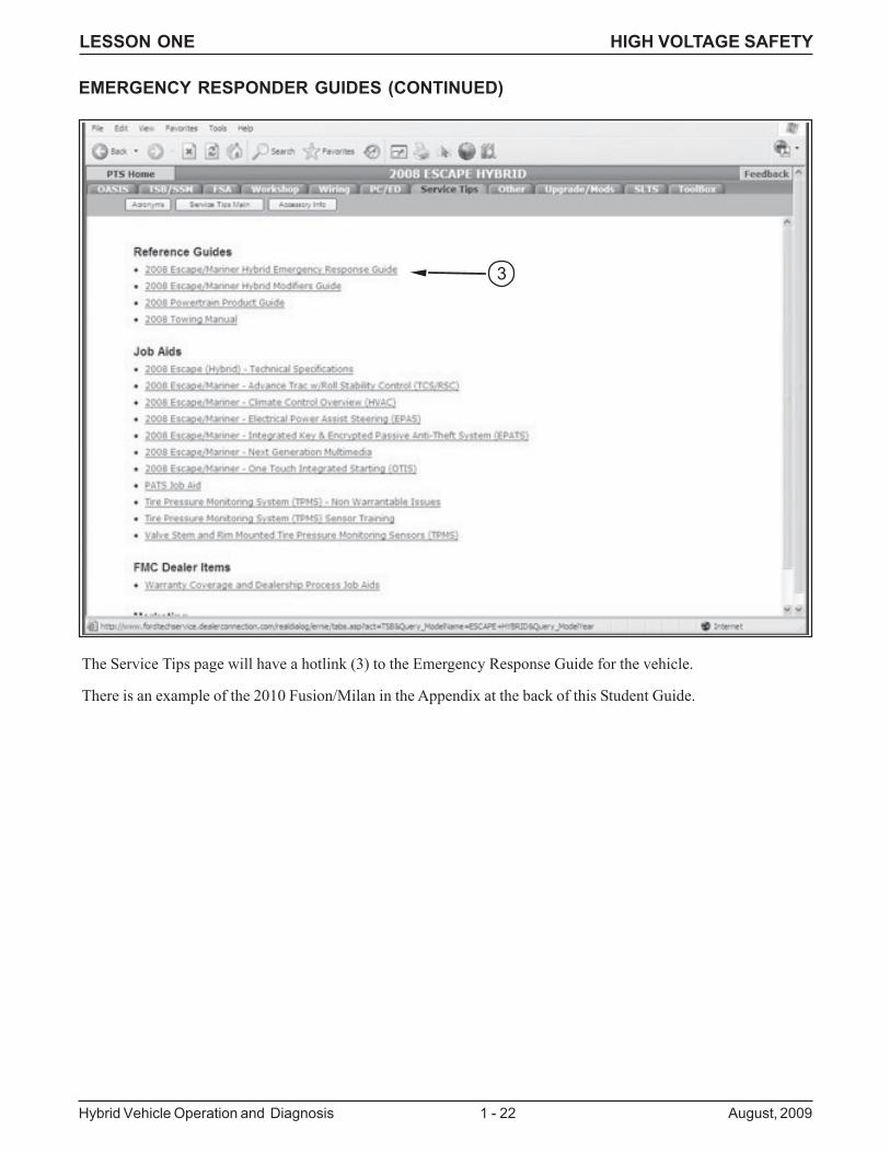
The Service Tips page will have a hotlink (3) to the Emergency Response Guide for the vehicle.
There is an example of the 2010 Fusion/Milan in the Appendix at the back of this Student Guide.
EMERGENCY RESPONDER GUIDES (CONTINUED)
3

LESSON ONE WORKSTATIONS
August, 2009 1 - 23 Hybrid Vehicle Operation and Diagnosis
LESSON ONEWORKSTATIONS 1-3
Workstation: Summary:
1 Escape/Mariner Component Location and Function (written)
2 Fusion/Milan Component Location and Function (hands-on)
3 Safety Quiz (written)
LESSON ONE WORKSTATION 1
Hybrid Vehicle Operation and Diagnosis 1 - 24 August, 2009
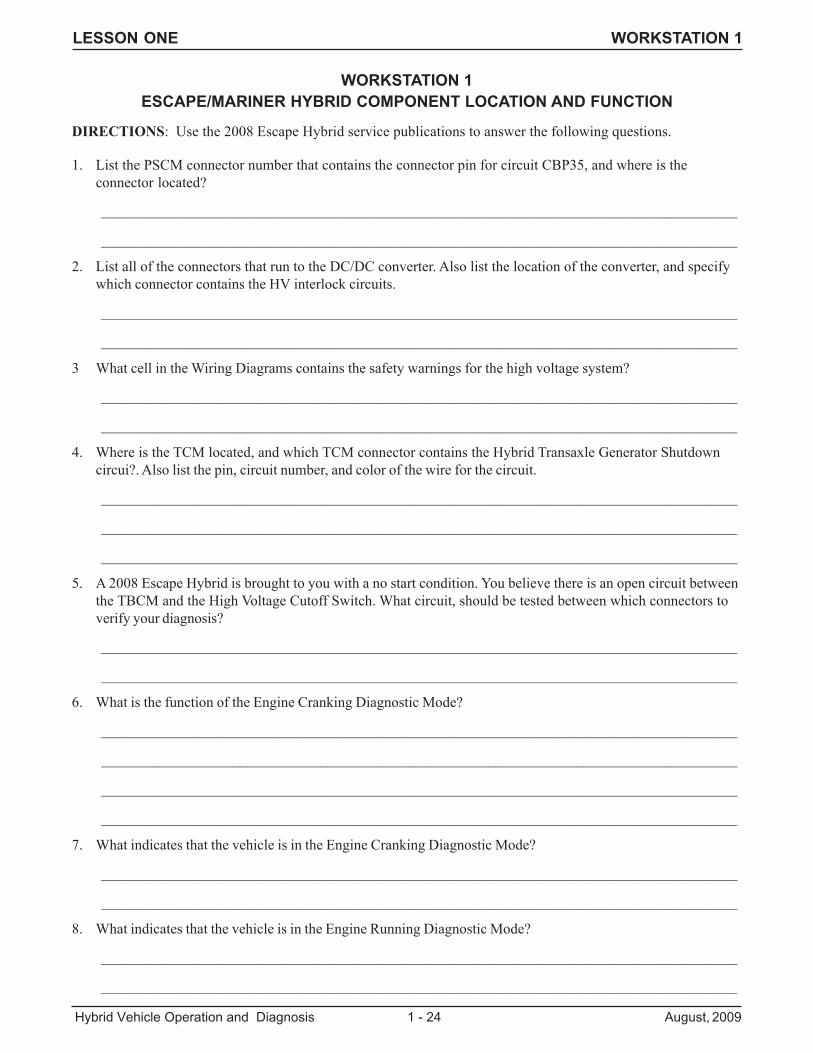
WORKSTATION 1ESCAPE/MARINER HYBRID COMPONENT LOCATION AND FUNCTION
DIRECTIONS: Use the 2008 Escape Hybrid service publications to answer the following questions.
1. List the PSCM connector number that contains the connector pin for circuit CBP35, and where is theconnector located?
_______________________________________________________________________________________
_______________________________________________________________________________________
2. List all of the connectors that run to the DC/DC converter. Also list the location of the converter, and specifywhich connector contains the HV interlock circuits.
_______________________________________________________________________________________
_______________________________________________________________________________________
3 What cell in the Wiring Diagrams contains the safety warnings for the high voltage system?
_______________________________________________________________________________________
_______________________________________________________________________________________
4. Where is the TCM located, and which TCM connector contains the Hybrid Transaxle Generator Shutdowncircui?. Also list the pin, circuit number, and color of the wire for the circuit.
_______________________________________________________________________________________
_______________________________________________________________________________________
_______________________________________________________________________________________
5. A 2008 Escape Hybrid is brought to you with a no start condition. You believe there is an open circuit betweenthe TBCM and the High Voltage Cutoff Switch. What circuit, should be tested between which connectors toverify your diagnosis?
_______________________________________________________________________________________
_______________________________________________________________________________________
6. What is the function of the Engine Cranking Diagnostic Mode?
_______________________________________________________________________________________
_______________________________________________________________________________________
_______________________________________________________________________________________
_______________________________________________________________________________________
7. What indicates that the vehicle is in the Engine Cranking Diagnostic Mode?
_______________________________________________________________________________________
_______________________________________________________________________________________
8. What indicates that the vehicle is in the Engine Running Diagnostic Mode?
_______________________________________________________________________________________
_______________________________________________________________________________________
LESSON ONE WORKSTATION 2
August, 2009 1 - 25 Hybrid Vehicle Operation and Diagnosis
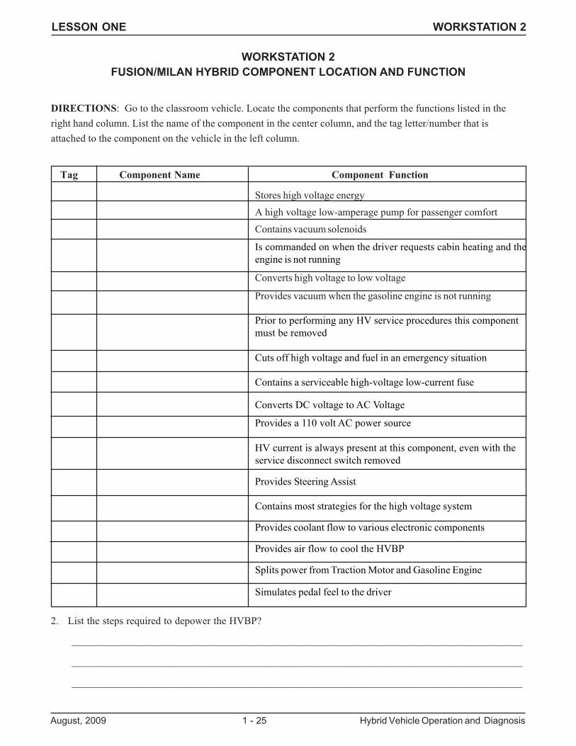
WORKSTATION 2FUSION/MILAN HYBRID COMPONENT LOCATION AND FUNCTION
DIRECTIONS: Go to the classroom vehicle. Locate the components that perform the functions listed in theright hand column. List the name of the component in the center column, and the tag letter/number that isattached to the component on the vehicle in the left column.
Tag Component Name Component Function
Stores high voltage energyA high voltage low-amperage pump for passenger comfortContains vacuum solenoids
Is commanded on when the driver requests cabin heating and theengine is not running
Converts high voltage to low voltage
Provides vacuum when the gasoline engine is not running
Prior to performing any HV service procedures this componentmust be removed
Cuts off high voltage and fuel in an emergency situation
Contains a serviceable high-voltage low-current fuse
Converts DC voltage to AC Voltage
Provides a 110 volt AC power source
HV current is always present at this component, even with theservice disconnect switch removed
Provides Steering Assist
Contains most strategies for the high voltage system
Provides coolant flow to various electronic components
Provides air flow to cool the HVBP
Splits power from Traction Motor and Gasoline Engine
Simulates pedal feel to the driver
2. List the steps required to depower the HVBP?
_______________________________________________________________________________________
_______________________________________________________________________________________
_______________________________________________________________________________________
LESSON ONE WORKSTATION 3
Hybrid Vehicle Operation and Diagnosis 1 - 26 August, 2009
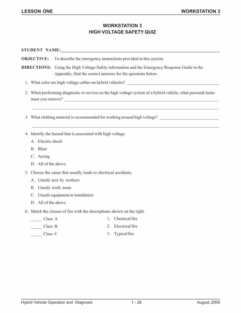
STUDENT NAME:____________________________________________________________________
OBJECTIVE: To describe the emergency instructions provided in this section.
DIRECTIONS: Using the High Voltage Safety information and the Emergency Response Guide in theAppendix, find the correct answers for the questions below.
1. What color are high voltage cables on hybrid vehicles? __________________________________________
2. When performing diagnostic or service on the high voltage system of a hybrid vehicle, what personal itemsmust you remove? _______________________________________________________________________
______________________________________________________________________________________
3. What clothing material is recommended for working around high voltage? ___________________________
______________________________________________________________________________________
4. Identify the hazard that is associated with high voltage.
A. Electric shock
B. Blast
C. Arcing
D. All of the above
5. Choose the cause that usually leads to electrical accidents.
A. Unsafe acts by workers
B. Unsafe work areas
C. Unsafe equipment or installation
D. All of the above
6. Match the classes of fire with the descriptions shown on the right.
_____ Class A
_____ Class B
_____ Class C
WORKSTATION 3HIGH VOLTAGE SAFETY QUIZ
1. Chemical fire
2. Electrical fire
3. Typical fire
LESSON ONE WORKSTATION 3
August, 2009 1 - 27 Hybrid Vehicle Operation and Diagnosis
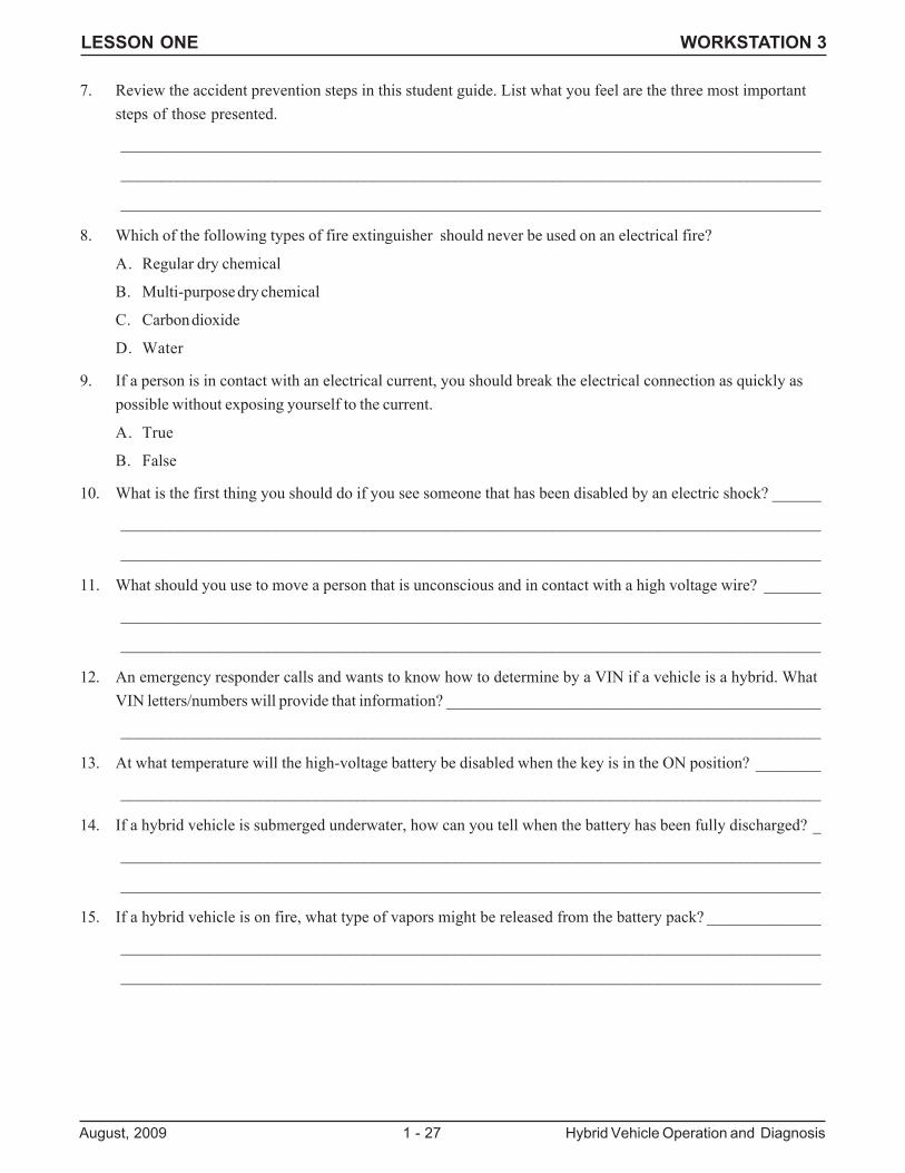
7. Review the accident prevention steps in this student guide. List what you feel are the three most importantsteps of those presented.
______________________________________________________________________________________
______________________________________________________________________________________
______________________________________________________________________________________
8. Which of the following types of fire extinguisher should never be used on an electrical fire?
A. Regular dry chemical
B. Multi-purpose dry chemical
C. Carbon dioxide
D. Water
9. If a person is in contact with an electrical current, you should break the electrical connection as quickly aspossible without exposing yourself to the current.
A. True
B. False
10. What is the first thing you should do if you see someone that has been disabled by an electric shock? ______
______________________________________________________________________________________
______________________________________________________________________________________
11. What should you use to move a person that is unconscious and in contact with a high voltage wire? _______
______________________________________________________________________________________
______________________________________________________________________________________
12. An emergency responder calls and wants to know how to determine by a VIN if a vehicle is a hybrid. WhatVIN letters/numbers will provide that information? ______________________________________________
______________________________________________________________________________________
13. At what temperature will the high-voltage battery be disabled when the key is in the ON position? ________
______________________________________________________________________________________
14. If a hybrid vehicle is submerged underwater, how can you tell when the battery has been fully discharged? _
______________________________________________________________________________________
______________________________________________________________________________________
15. If a hybrid vehicle is on fire, what type of vapors might be released from the battery pack? ______________
______________________________________________________________________________________
______________________________________________________________________________________

LESSON ONE WORKSTATION 3
Hybrid Vehicle Operation and Diagnosis 1 - 28 August, 2009

LESSON ONE WORKSTATIONS
August, 2009 1 - 29 Hybrid Vehicle Operation and Diagnosis
LESSON ONEWORKSTATIONS 4-6
Workstation: Summary:
4 Escape/Mariner Brake Service (video-written)
5 High Voltage Service (hands-on)
6 Hybrid Diagnostic Procedures (written)
LESSON ONE WORKSTATION 4
Hybrid Vehicle Operation and Diagnosis 1 - 30 August, 2009
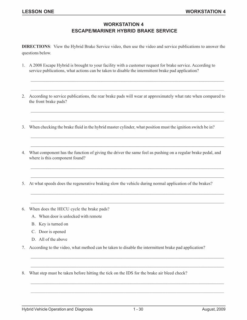
WORKSTATION 4 ESCAPE/MARINER HYBRID BRAKE SERVICE
DIRECTIONS: View the Hybrid Brake Service video, then use the video and service publications to answer thequestions below.
1. A 2008 Escape Hybrid is brought to your facility with a customer request for brake service. According toservice publications, what actions can be taken to disable the intermittent brake pad application?
_______________________________________________________________________________________
_______________________________________________________________________________________
2. According to service publications, the rear brake pads will wear at approximately what rate when compared tothe front brake pads?
_______________________________________________________________________________________
_______________________________________________________________________________________
3. When checking the brake fluid in the hybrid master cylinder, what position must the ignition switch be in?
_______________________________________________________________________________________
_______________________________________________________________________________________
4. What component has the function of giving the driver the same feel as pushing on a regular brake pedal, andwhere is this component found?
_______________________________________________________________________________________
_______________________________________________________________________________________
5. At what speeds does the regenerative braking slow the vehicle during normal application of the brakes?
_______________________________________________________________________________________
_______________________________________________________________________________________
6. When does the HECU cycle the brake pads?
A. When door is unlocked with remote
B. Key is turned on
C. Door is opened
D. All of the above
7. According to the video, what method can be taken to disable the intermittent brake pad application?
_______________________________________________________________________________________
_______________________________________________________________________________________
8. What step must be taken before hitting the tick on the IDS for the brake air bleed check?
_______________________________________________________________________________________
_______________________________________________________________________________________
LESSON ONE WORKSTATION 4
August, 2009 1 - 31 Hybrid Vehicle Operation and Diagnosis
9. What pressure is the Rotunda brake bleeder initially set at when performing brake bleeding?
_______________________________________________________________________________________
_______________________________________________________________________________________
10. After opening the right front bleeder screw, you press the tick on the IDS. How many times must you depressthe brake pedal?
_______________________________________________________________________________________
_______________________________________________________________________________________
11. What does it indicate when the IDS presents a code OB?
_______________________________________________________________________________________
_______________________________________________________________________________________
12. What are the major inputs to the brake system?
_______________________________________________________________________________________
_______________________________________________________________________________________
13. What does a DTC C1524 indicate?
_______________________________________________________________________________________
_______________________________________________________________________________________
14. What code indicates that the brake system initialization is incomplete?
_______________________________________________________________________________________
_______________________________________________________________________________________
WORKSTATION 4 ESCAPE/MARINER HYBRID BRAKE SERVICE (CONTINUED)
LESSON ONE WORKSTATION 5
Hybrid Vehicle Operation and Diagnosis 1 - 32 August, 2009
WORKSTATION 5FUSION/MILAN HYBRID HIGH VOLTAGE SERVICE
DIRECTIONS: Go to the Fusion/Milan Hybrid classroom vehicle. The customer says that there is a “no batterycharging” message displayed in the instrument panel. Diagnose this concern and answer the following questions.
.1. Can you verify this concern. Are there any messages being displayed in the message center?
_______________________________________________________________________________________
2. Does your visual inspection reveal any obvious flaws?
_______________________________________________________________________________________
3. Perform the KOEO self-test, then clear all DTCs. Repeat the KOEO (ALL CMDTCs) self-test and list anyCMDTCs found and list the module in which the DTCS are stored?
_______________________________________________________________________________________
_______________________________________________________________________________________
4. Compare the service publication description for each of the DTC’s listed. Do you find anything in common inthese descriptions?
_______________________________________________________________________________________
_______________________________________________________________________________________
NOTE: INFORM YOUR INSTRUCTOR BEFORE PERFORMING THE NEXT STEP
5. Select the G_INV_V and M_INV_V PID from the TCM Datalogger menu. Turn the ignition to the ONposition and pull out the Service Disconnect Switch. What occurs and what does this indicate?
_______________________________________________________________________________________
6. Select and perform the pinpoint test that you think is most likely to find the fault? List the pinpoint test and it’sresults below, then notify your instructor of your findings.
_______________________________________________________________________________________
_______________________________________________________________________________________
_______________________________________________________________________________________
7. What section of the Workshop Manual contains directions for performing this service?
_______________________________________________________________________________________
_______________________________________________________________________________________
8. At the beginning of the directions for replacing this component, summarize the WARNING about the servicedisconnect switch.
_______________________________________________________________________________________
_______________________________________________________________________________________
LESSON ONE WORKSTATION 5
August, 2009 1 - 33 Hybrid Vehicle Operation and Diagnosis
WORKSTATION 5FUSION/MILAN HYBRID HIGH VOLTAGE SERVICE (CONTINUED)
9. Why must the high-voltage/low-current bus bar be removed during this service procedure?
_______________________________________________________________________________________
_______________________________________________________________________________________
10. During installation of the component you are directed to replace, what is torque specifications for the high-voltage/high-current positive cable nut and high-voltage/low-current fuse nuts.(NOTE: WHENPERFORMING THIS SERVICE ON THE CLASSROOM VEHICLE, ONLY TORQUE THEFASTENERS TO 1/2 THE SPECIFIED TORQUE).
_______________________________________________________________________________________
_______________________________________________________________________________________
11. Replace the component as described in service publications. NOTIFY YOUR INSTRUCTOR when you havethe faulty component removed from the vehicle.
RETURN THE WORKSTATION TO THE CONDITION IN WHICH YOU FOUND IT

LESSON ONE WORKSTATION 6
Hybrid Vehicle Operation and Diagnosis 1 - 34 August, 2009
WORKSTATION 6HYBRID DIAGNOSTIC PROCEDURES (PART 1)
DIRECTIONS: Use IDS recording L1_WKS6 of the 2010 Milan to answer the following questions.
1. The three PIDS listed below are shown in this recording. Write the IDS definition next to each PID.
PID PID Description
PID PID DescriptionGENMODERPM TCM
VSS
2. List the PID readings at approximately 8 seconds into the recording.
PID PID DescriptionGENMODERPM TCM
VSS
3. List the PID readings at approximately 28 seconds of the recording.
GENMODERPM TCM
VSS
4. Based upon your observations, what does the GENMODE PID indicate when the gasoline engine is runningand what does it indicate when the engine is off?
_______________________________________________________________________________________
5. Review the entire recording. Based upon your observations, what will the GENMODE PID indicate when thegasoline engine is starting and what will it indicate when the engine is shutting down?
_______________________________________________________________________________________
_______________________________________________________________________________________
6. How will viewing these three PIDs when making Datalogger recordings help you during diagnostics?
_______________________________________________________________________________________
_______________________________________________________________________________________
_______________________________________________________________________________________

LESSON ONE WORKSTATION 6
August, 2009 1 - 35 Hybrid Vehicle Operation and Diagnosis

LESSON ONE WORKSTATION 6
Hybrid Vehicle Operation and Diagnosis 1 - 36 August, 2009
Diagnostic Step Result
WORKSTATION 6HYBRID DIAGNOSTIC PROCEDURES (PART 2)
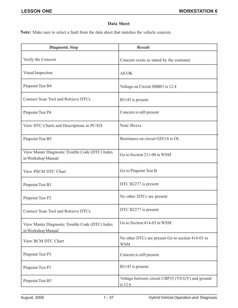
DIRECTIONS: A 2008 Escape Hybrid is brought to you with a customer concern of “Hard Steering”.
1. What type of EPAS system does this vehicle have?
_______________________________________________________________________________________
2. Perform the diagnosis for the concern using the service publications and the Data Sheet provided bycomparing the service publication pinpoint test steps to the pinpoint test steps listed.
The RESULTS COLUMN of the table lists the results of the tests performed, use these results to select thenext step that must be performed.
Continue doing this until you have identified the cause of the concern and verified the repair.
NOTE: SOME STEPS IN THE DATA SHEET ARE NOT USED IN THE DIAGNOSIS AND ARE ONLYINCLUDED AS DISTRACTORS. Select only the steps that are required.
2. What should be done to repair this concern?
_______________________________________________________________________________________
LESSON ONE WORKSTATION 6
August, 2009 1 - 37 Hybrid Vehicle Operation and Diagnosis
Verify the Concern
Visual Inspection
Pinpoint Test B4
Connect Scan Tool and Retrieve DTCs
Pinpoint Test P4
View DTC Charts and Descriptions in PC/ED
Pinpoint Test B5
View Master Diagnostic Trouble Code (DTC) Indexin Workshop Manual
View PSCM DTC Chart
Pinpoint Test B1
Pinpoint Test P2
Connect Scan Tool and Retrieve DTCs
View Master Diagnostic Trouble Code (DTC) Indexin Workshop Manual
View BCM DTC Chart
Pinpoint Test P3
Pinpoint Test P1
Pinpoint Test B3
Concern exists as stated by the customer
All OK
Voltage on Circuit SBB01 is 12.4
B1143 is present
Concern is still present
Note: Bxxxx
Resistance on circuit GD116 is OL
Go to Section 211-00 in WSM
Go to Pinpoint Test B
DTC B2277 is present
No other DTCs are present
DTC B2277 is present
Go to Section 414-03 in WSM
No other DTCs are present Go to section 414-03 inWSM
Concern is still present
B1143 is present
Voltage between circuit CBP35 (YE/GY) and groundis 12.6
Diagnostic Step Result
Data Sheet
Note: Make sure to select a fault from the data sheet that matches the vehicle concern.

LESSON ONE WORKSTATION 6
Hybrid Vehicle Operation and Diagnosis 1 - 38 August, 2009

LESSON TWO DEMONSTRATION
August, 2009 2 - 1 Hybrid Vehicle Operation and Diagnosis
DEMONSTRATIONInteractive Diagnostics
Engine Running/Cranking Diagnosis Mode
LESSON TWO DEMONSTRATION
Hybrid Vehicle Operation and Diagnosis 2 - 2 August, 2009
1. What requirements must be met for the IDS to be utilized for Interactive Diagnostics?
_______________________________________________________________________________________
_______________________________________________________________________________________
2. Once connected to the PTS website, how do you begin the diagnostic process?
_______________________________________________________________________________________
_______________________________________________________________________________________
3. Once in the Workshop Manual, what section was selected, and what topic was selected?
_______________________________________________________________________________________
_______________________________________________________________________________________
4. On this page, what is unique about the left hand menu of the Workshop Manual?
_______________________________________________________________________________________
_______________________________________________________________________________________
5. In order to continue the diagnosis, what must be selected on this page?
_______________________________________________________________________________________
_______________________________________________________________________________________
6. What does the IDS automatically perform when this page is selected?
_______________________________________________________________________________________
_______________________________________________________________________________________
7. What is the next selection that must be made in order to continue the diagnosis?
_______________________________________________________________________________________
_______________________________________________________________________________________
8. From this page, what must be done to continue?
_______________________________________________________________________________________
_______________________________________________________________________________________
DEMONSTRATIONHYBRID VEHICLE DIAGNOSTICS
DIRECTIONS: As your instructor demonstrates the operation and utilization of IDS Interactive Diagnostics,answer the questions listed below.
LESSON TWO DEMONSTRATION
August, 2009 2 - 3 Hybrid Vehicle Operation and Diagnosis
9. What question is now asked by the IDS, and what will result based upon the answer to the question?
_______________________________________________________________________________________
_______________________________________________________________________________________
10. Once you are directed to the page based upon your answer to the question, what is shown on that page?
_______________________________________________________________________________________
_______________________________________________________________________________________
11. What has happened to the left menu on this page?
_______________________________________________________________________________________
_______________________________________________________________________________________
12. If a VMM is connected to the vehicle, what action will the IDS automatically perform during your diagnosis?
_______________________________________________________________________________________
_______________________________________________________________________________________
13. What additional aid does Interactive Diagnostics offer if you require assistance from the Technical Hotline?
_______________________________________________________________________________________
_______________________________________________________________________________________
14. Place the vehicle in the Engine Cranking Diagnostic Mode by performing the following steps:
1 Key in the ON position with the engine OFF.
2 Within 5 seconds of the key in the ON position, fully apply the accelerator pedal and hold for 10 seconds.
3 Within 5 seconds release the accelerator pedal, shift the gear selector to the NEUTRAL position and fullyapply the accelerator pedal.
4 Hold the accelerator pedal fully applied for 10 seconds.
5 Release the accelerator pedal and shift the gear selector to the PARK position.
15. Place the vehicle in the Engine Running Diagnostic Mode by performing the following steps:
1 Key in the ON position with the engine OFF.
2 Within 5 seconds of the key in the ON position, fully apply the accelerator pedal and hold for 10 seconds.
3 Within 5 seconds release the accelerator pedal, shift the gear selector to the DRIVE position and fullyapply the accelerator pedal.
4 Hold the accelerator pedal fully applied for 10 seconds.
5 Release the accelerator pedal and shift the gear selector to the PARK position.
DEMONSTRATIONHYBRID VEHICLE DIAGNOSTICS (CONTINUED)

LESSON TWO DEMONSTRATION
Hybrid Vehicle Operation and Diagnosis 2 - 4 August, 2009
LESSON TWO WORKSTATIONS
August, 2009 2 - 5 Hybrid Vehicle Operation and Diagnosis
LESSON TWOWORKSTATIONS
Workstation: Summary:
1 IDS Hybrid Diagnosis (IDS recording and written)
2 Fusion/Milan Hybrid Diagnosis (hands-on)
3 Hybrid Diagnostic Procedures (IDS recording and written)
LESSON TWO WORKSTATION 1
Hybrid Vehicle Operation and Diagnosis 2 - 6 August, 2009
WORKSTATION 1IDS HYBRID DIAGNOSIS (PART 1)
SCENARIO/DIRECTIONS: A 2010 Fusion Hybrid is brought to you from the body shop that has been in aflood. The vehicle is a no-start and the red triangle warning light is illuminated. P0AA6:00 is present in theBCM memory? Using the IDS open recording L2_WKS1 and service publications, answer the followingquestions about this concern.
1. What service publication and section of that publication describes this DTC?
_______________________________________________________________________________________
2. What is the DTC Chart description of this DTC?
_______________________________________________________________________________________
3. Which pinpoint test are you directed to for diagnostic procedures?
_______________________________________________________________________________________
4. According to the pinpoint test introduction, what does the BECM monitor that could cause this DTC?
_______________________________________________________________________________________
5. In step 1 of this pinpoint test, you are directed to view specific PIDs. Go to IDS recording and view thesePIDs. List each PID and record the value shown on the IDS.
_______________________________________________________________________________________
_______________________________________________________________________________________
_______________________________________________________________________________________
6. What resistance value is considered a failure on this system?
_______________________________________________________________________________________
7. If these readings were/are out of specifications, what might be the cause of the concern based on the vehiclehistory and description of the pinpoint test?
_______________________________________________________________________________________
8. This vehicle is going to be repainted. Your facility uses a paint booth for paint drying. Is there any specialinformation that you must provide the body shop manager to prevent vehicle component damage?
_______________________________________________________________________________________
_______________________________________________________________________________________
LESSON TWO WORKSTATION 1
August, 2009 2 - 7 Hybrid Vehicle Operation and Diagnosis
1. What service publication and section of that publication describes this DTC?
_______________________________________________________________________________________
2. What is the DTC Chart description of this DTC?
_______________________________________________________________________________________
3. Which pinpoint test are you directed to for diagnostic procedures?
_______________________________________________________________________________________
4. According to the pinpoint test introduction, what does the BECM monitor that could cause this DTC?
_______________________________________________________________________________________
5. In step 2 of this pinpoint test, you are directed to view specific PIDs. Go to IDS recording and view these PIDs.List each PID and record the value shown on the IDS?
_______________________________________________________________________________________
_______________________________________________________________________________________
6. According to the pinpoint test, what actions should you take?
_______________________________________________________________________________________
_______________________________________________________________________________________
WORKSTATION 1HYBRID DIAGNOSTIC PROCEDURES (PART 2)
SCENARIO/DIRECTIONS: A 2010 Fusion Hybrid is brought to you from the vehicle prep department:
The vehicle now seems to run normally, but the prep technician said that when he first attempted to start thevehicle it would not start and the red triangle light was illuminated.
The next day, when the service manager tried to start it, the vehicle started normally. However, the servicemanager wants you to check the vehicle out.
After visual inspecting the vehicle, you find no obvious faults. Then you retrieve DTCs and find CMDTC ofP0A7D00 stored in the BECM memory. Use IDS recording L2_WKS1 and service publications to answer thefollowing questions about this concern.
Worksheet Continued on Next Page
LESSON TWO WORKSTATION 1
Hybrid Vehicle Operation and Diagnosis 2 - 8 August, 2009
WORKSTATION 1HYBRID DIAGNOSTIC PROCEDURES (PART 2) (continued)
SCENARIO/DIRECTIONS: Use the appropriate service publications to answer the following questions.
7. On a 2010 Fusion Hybrid, what action will the ABS module take if there is a vacuum pump motor concern?
_______________________________________________________________________________________
_______________________________________________________________________________________
8. On a 2010 Fusion Hybrid, what is the flow direction in the M/E cooling system (from component tocomponent)?
_______________________________________________________________________________________
______________________________________________________________________________________________________________________________________________________________________________
9. On a 2010 Fusion Hybrid, what action must be taken before welding on the vehicle?
_______________________________________________________________________________________
_______________________________________________________________________________________
10. On a 2010 Fusion Hybrid, what type of conventional brake system is used?
_______________________________________________________________________________________
_______________________________________________________________________________________
11. On a 2010 Fusion Hybrid, what pinpoint test are you directed to for a DTC P2600, and what component willset this code?
_______________________________________________________________________________________
_______________________________________________________________________________________
12. On a 2008 Escape Hybrid, how many lift points are used to remove the HV battery pack?
_______________________________________________________________________________________
_______________________________________________________________________________________
LESSON TWO WORKSTATION 2
August, 2009 2 - 9 Hybrid Vehicle Operation and Diagnosis
WORKSTATION 2FUSION/MILAN DIAGNOSTIC PROCEDURES
SCENARIO/DIRECTIONS: A 2010 Fusion Hybrid is towed to your facility with a customer concern of no startand the red hazard triangle is illuminated. Diagnose the cause of this concern and answer the questions below.
1. Can you verify the customer concern?
_______________________________________________________________________________________
2. Your visual inspection revealed nothing out of the ordinary so you retrieve DTCs. List any DTCs found below.
_______________________________________________________________________________________
_______________________________________________________________________________________
3. Which service publication contains the Master DTC chart for this vehicle?
_______________________________________________________________________________________
4. What is the description of this DTC?
_______________________________________________________________________________________
5. What pinpoint test are you directed to?
_______________________________________________________________________________________
6. Summarize the WARNING in the first step of the pinpoint test to which you are directed.
_______________________________________________________________________________________
_______________________________________________________________________________________
7. List the Pinpoint Test Steps you are directed to perform and their results in the table below.
Diagnostic Step Result
8. What action are you directed to take to correct this concern?
_______________________________________________________________________________________
RETURN THE WORKSTATION TO THE CONDITION IN WHICH YOU FOUND IT
LESSON TWO WORKSTATION 3
Hybrid Vehicle Operation and Diagnosis 2 - 10 August, 2009
WORKSTATION 3HYBRID DIAGNOSTIC PROCEDURES (PART 1)
SCENARIO/DIRECTIONS: Open the IDS software on the classroom PC and load the Escape/Mariner L2WKS 3 file. Use the Datalogger files and service publications to answer the following questions.
1. What size and type of gasoline engine is installed in this vehicle?
_______________________________________________________________________________________
2. At what vehicle speed does the gasoline engine start for the first time on this recording?
_______________________________________________________________________________________
3. When the gasoline engine starts for the first time, what is the MECT_V reading?
_______________________________________________________________________________________
4. Go to Pinpoint Test DN in the PC/ED manual for this vehicle. Using the information in the introduction of thispinpoint test, what is the approximate operating temperature of the ME coolant?
_______________________________________________________________________________________
5. Based upon the information in questions 3 & 4, approximately what should the resistance be for the MECTsensor if you measured it with a ohm meter?
_______________________________________________________________________________________
6. At about what time in the recording does the HPUMP# PID indicate Off for the first time?
_______________________________________________________________________________________
7. If you were unsure of heater pump operation, what can you do using the IDS to determine if it operates?
_______________________________________________________________________________________

LESSON TWO WORKSTATION 3
August, 2009 2 - 11 Hybrid Vehicle Operation and Diagnosis
Page Intentionally Left Blank
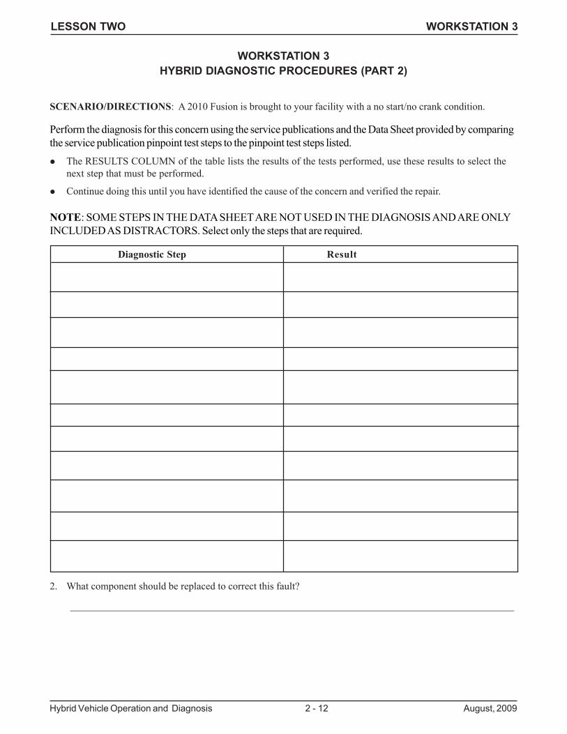
LESSON TWO WORKSTATION 3
Hybrid Vehicle Operation and Diagnosis 2 - 12 August, 2009
WORKSTATION 3HYBRID DIAGNOSTIC PROCEDURES (PART 2)
SCENARIO/DIRECTIONS: A 2010 Fusion is brought to your facility with a no start/no crank condition.
Perform the diagnosis for this concern using the service publications and the Data Sheet provided by comparingthe service publication pinpoint test steps to the pinpoint test steps listed.
The RESULTS COLUMN of the table lists the results of the tests performed, use these results to select thenext step that must be performed.
Continue doing this until you have identified the cause of the concern and verified the repair.
NOTE: SOME STEPS IN THE DATA SHEET ARE NOT USED IN THE DIAGNOSIS AND ARE ONLYINCLUDED AS DISTRACTORS. Select only the steps that are required.
Diagnostic Step Result
2. What component should be replaced to correct this fault?
_______________________________________________________________________________________
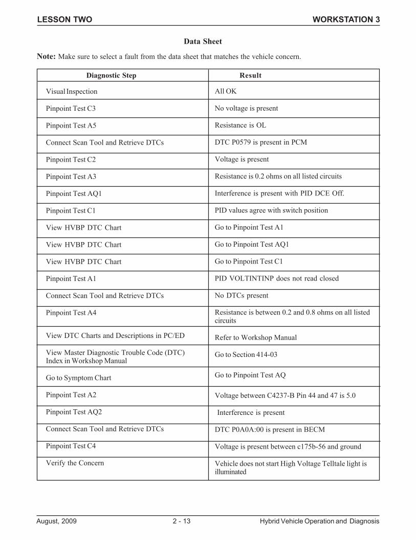
LESSON TWO WORKSTATION 3
August, 2009 2 - 13 Hybrid Vehicle Operation and Diagnosis
Diagnostic Step Result
Visual Inspection
Pinpoint Test C3
Pinpoint Test A5
Connect Scan Tool and Retrieve DTCs
Pinpoint Test C2
Pinpoint Test A3
Pinpoint Test AQ1
Pinpoint Test C1
View HVBP DTC Chart
View HVBP DTC Chart
View HVBP DTC Chart
Pinpoint Test A1
Connect Scan Tool and Retrieve DTCs
Pinpoint Test A4
View DTC Charts and Descriptions in PC/ED
View Master Diagnostic Trouble Code (DTC)Index in Workshop Manual
Go to Symptom Chart
Pinpoint Test A2
Pinpoint Test AQ2
Connect Scan Tool and Retrieve DTCs
Pinpoint Test C4
Verify the Concern
All OK
No voltage is present
Resistance is OL
DTC P0579 is present in PCM
Voltage is present
Resistance is 0.2 ohms on all listed circuits
Interference is present with PID DCE Off.
PID values agree with switch position
Go to Pinpoint Test A1
Go to Pinpoint Test AQ1
Go to Pinpoint Test C1
PID VOLTINTINP does not read closed
No DTCs present
Resistance is between 0.2 and 0.8 ohms on all listedcircuits
Refer to Workshop Manual
Go to Section 414-03
Go to Pinpoint Test AQ
Voltage between C4237-B Pin 44 and 47 is 5.0
Interference is present
DTC P0A0A:00 is present in BECM
Voltage is present between c175b-56 and ground
Vehicle does not start High Voltage Telltale light isilluminated
Data Sheet
Note: Make sure to select a fault from the data sheet that matches the vehicle concern.

LESSON TWO WORKSTATION 3
Hybrid Vehicle Operation and Diagnosis 2 - 14 August, 2009
LESSON TWO ACRONYMS
August, 2009 Acronym - 1 Hybrid Vehicle Operation and Diagnosis
HYBRID ACRONYMS AND TERMS
ACCM Air Conditioning Control Module
Atkinson Cycle Engine operation where intake valve is open during portion of compression stroke
BCM Battery Control Module
BECM Battery Energy Control Module
BEC Bussed Electrical Center
BPSM Battery Pack Sensor Module
Contactor High Voltage Relay
eCVT Electronic Continuously Variable Transmission
EPAS Electric Power Assist Steering
DC/DC Direct Current to Direct Current
EHB Electro- Hydraulic Brakes
FEAD Front End Accessory Drive
Heater Pump An electric pump that operates to circulates engine coolant to provide cabin heat
HV High Voltage
HVBP High Voltage Battery Pack
HVTB High Voltage Traction Battery (Same as HVBP)
LV Low Voltage (12 volts)
M/E Motor Electronics
PSCM Power Steering Control Module
RCM Restraints Control Module
SBA Simulated Brake Application
SKS Silent Key Start
TBCM Traction Battery Control Module (Same as BCM)
TCM Transmission Control Module

HYBRID VEHICLE OPERATION AND DIAGNOSIS HYBRID ACRONYMS AND TERMS
Hybrid Vehicle Operation and Diagnosis Acronym - 2 August, 2009

Appendix

2010FUSION HYBRIDMILAN HYBRID
EMERGENCY RESPONSE GUIDE
FCS-14265-10
1
2010 Fusion Hybrid, Milan Hybrid Emergency Response Guide, 02/2009
FOREWORDThe emergency response procedures for the Fusion Hybrid and Milan Hybridvehicles are similar to those for traditional gasoline-powered vehicles with theaddition of special considerations for the high-voltage electric system components.
The Fusion Hybrid or Milan Hybrid vehicles use a conventional gasoline engine inaddition to an electric motor to power the vehicle. The energy used to power thevehicle comes from gasoline (used by the internal combustion engine) and electricity(used by the electric motor).
• Gasoline is stored in a traditional fuel tank.
• Electricity is stored in a high-voltage battery pack.
The combination of a gasoline engine and electric motor provides for improvedperformance (V6 performance with a 4-cylinder engine and electric motor),reduced emissions and improved fuel economy. The high-voltage system isself contained, never needing to be plugged into an electrical outlet for recharging.The system incorporates a generator that recharges the high-voltage batteries duringcruising and braking from the engine.
The information in this guide will allow response to emergencies involving FusionHybrid or Milan Hybrid vehicles to be as safe as with conventional vehicles.
The Fusion Hybrid and Milan Hybrid vehicles have been designed with many safetyfeatures for your protection. These features help provide safe access to the vehicleunder various conditions. However, when approaching a high-voltage vehicle ina fire, rescue or recovery situation, always follow one industry standard rule:
ALWAYS ASSUME THE VEHICLE’SHIGH-VOLTAGE SYSTEM IS POWERED UP !
FCS-14265-10
2
2010 Fusion Hybrid, Milan Hybrid Emergency Response Guide, 02/2009
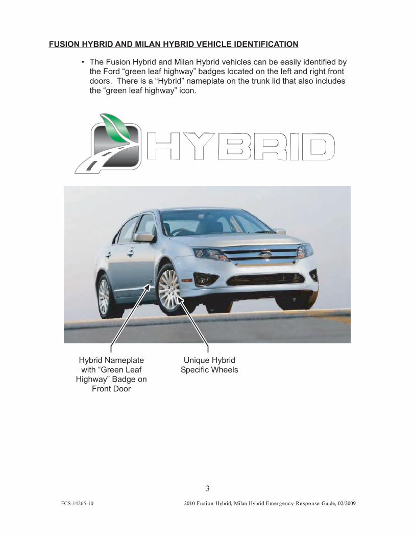
FUSION HYBRID AND MILAN HYBRID VEHICLE IDENTIFICATION
• The Fusion Hybrid and Milan Hybrid vehicles can be easily identified bythe Ford “green leaf highway” badges located on the left and right frontdoors. There is a “Hybrid” nameplate on the trunk lid that also includesthe “green leaf highway” icon.
Hybrid Nameplatewith “Green Leaf
Highway” Badge onFront Door
Unique HybridSpecific Wheels
FCS-14265-10
3
2010 Fusion Hybrid, Milan Hybrid Emergency Response Guide, 02/2009
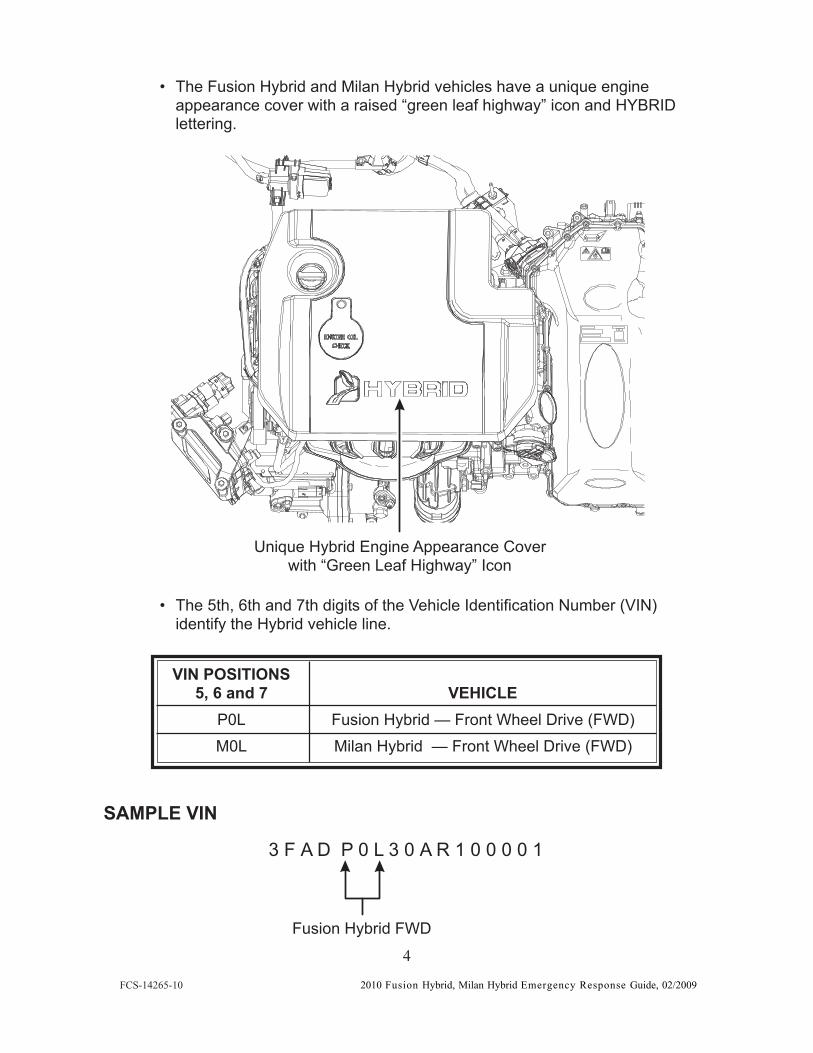
• The Fusion Hybrid and Milan Hybrid vehicles have a unique engineappearance cover with a raised “green leaf highway” icon and HYBRIDlettering.
• The 5th, 6th and 7th digits of the Vehicle Identification Number (VIN)identify the Hybrid vehicle line.
VIN POSITIONS5, 6 and 7 VEHICLE
P0L Fusion Hybrid — Front Wheel Drive (FWD)M0L Milan Hybrid — Front Wheel Drive (FWD)
Unique Hybrid Engine Appearance Coverwith “Green Leaf Highway” Icon
SAMPLE VIN
3 F A D P 0 L 3 0 A R 1 0 0 0 0 1
Fusion Hybrid FWD
FCS-14265-10
4
2010 Fusion Hybrid, Milan Hybrid Emergency Response Guide, 02/2009
HIGH-VOLTAGE ELECTRICAL DISCONNECT FEATURES
The following list describes certain features that have been incorporated into theHybrid vehicles that allow for either simple or automatic shutoff of the high-voltageelectrical systems.
• High-Voltage Fuse — In the event of a high-current short circuit,the high-voltage fuse will open, disabling the high-voltage system.
• High-Voltage Interlock Circuit — Whenever a high-voltage connectoris disconnected, the high-voltage interlock circuit opens and disablesthe high-voltage system.
• Ignition Key in OFF Position — Any time the ignition lock cylinder is inthe OFF position, the high-voltage system is disabled.
• High-Voltage Service Disconnect — Whenever the high-voltageservice disconnect (located behind the rear seat) is removed, thehigh-voltage system is disabled. For additional information, refer toPage 9 in this manual.
• Thermal Sensors — In the event the ignition key is left in the ON positionand the high-voltage battery temperature exceeds 60°C (140°F),thermal sensors located near the high-voltage battery will automaticallydisable the high-voltage battery.
FCS-14265-10
5
2010 Fusion Hybrid, Milan Hybrid Emergency Response Guide, 02/2009
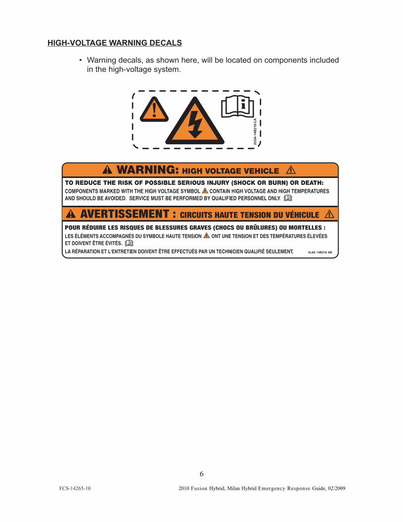
HIGH-VOLTAGE WARNING DECALS
• Warning decals, as shown here, will be located on components includedin the high-voltage system.
AC- 812
B4 1-A5
U2
FCS-14265-10
6
2010 Fusion Hybrid, Milan Hybrid Emergency Response Guide, 02/2009
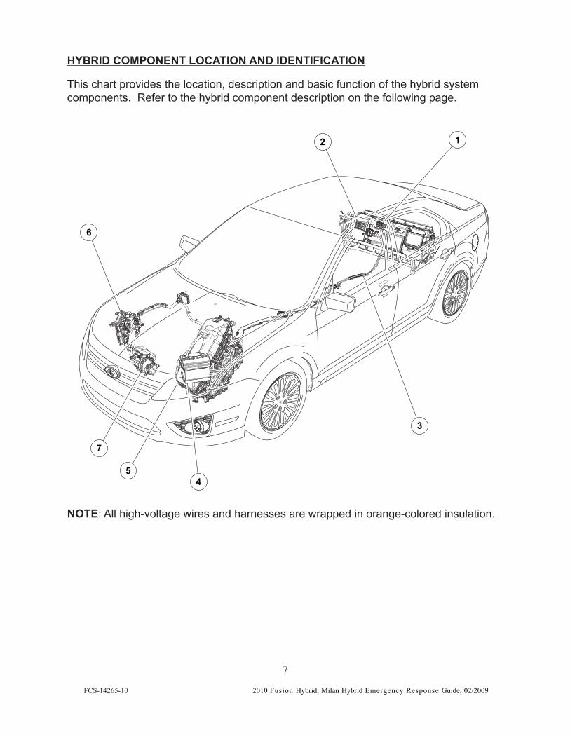
HYBRID COMPONENT LOCATION AND IDENTIFICATION
This chart provides the location, description and basic function of the hybrid systemcomponents. Refer to the hybrid component description on the following page.
NOTE: All high-voltage wires and harnesses are wrapped in orange-colored insulation.
45
6
7
2
3
1
FCS-14265-10
7
2010 Fusion Hybrid, Milan Hybrid Emergency Response Guide, 02/2009
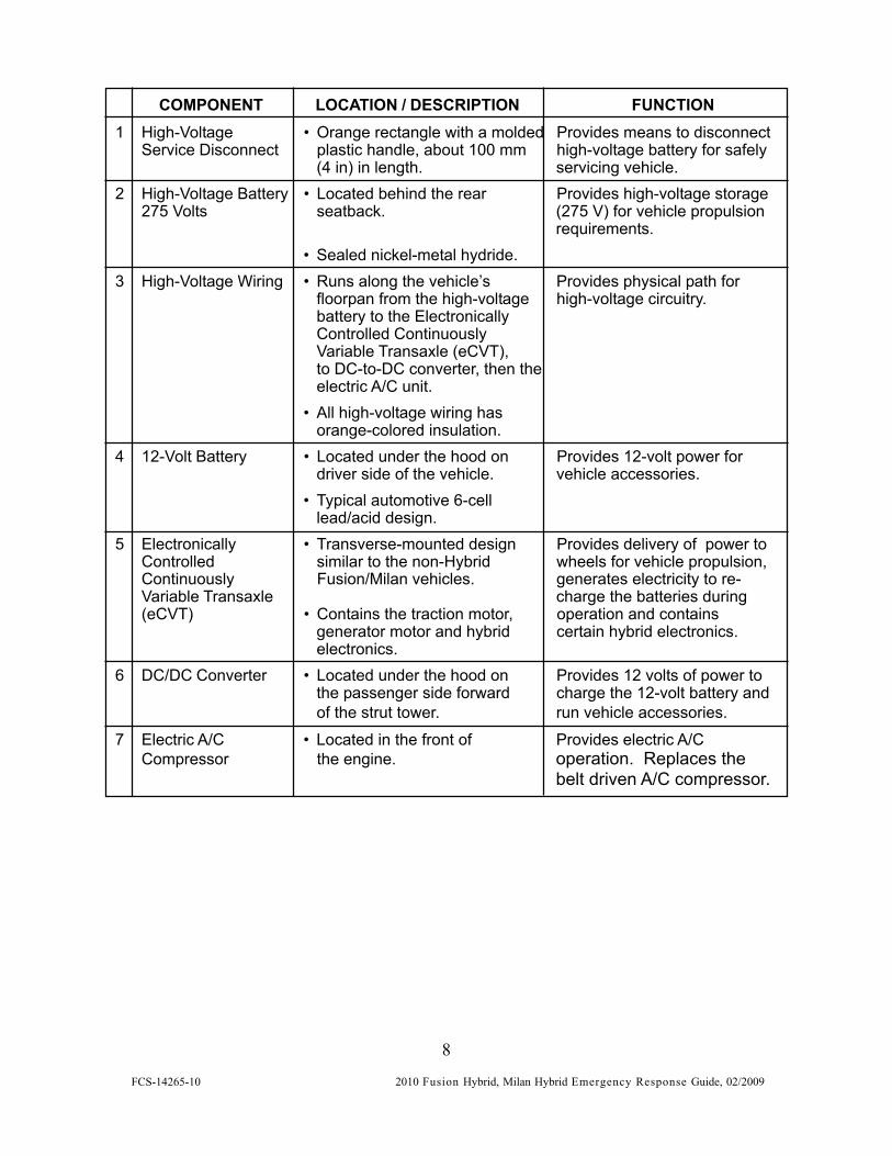
COMPONENT LOCATION / DESCRIPTION FUNCTION1 High-Voltage • Orange rectangle with a molded Provides means to disconnect
Service Disconnect plastic handle, about 100 mm high-voltage battery for safely(4 in) in length. servicing vehicle.
2 High-Voltage Battery • Located behind the rear Provides high-voltage storage275 Volts seatback. (275 V) for vehicle propulsion
requirements.• Sealed nickel-metal hydride.
3 High-Voltage Wiring • Runs along the vehicle’s Provides physical path forfloorpan from the high-voltage high-voltage circuitry.battery to the ElectronicallyControlled ContinuouslyVariable Transaxle (eCVT),to DC-to-DC converter, then theelectric A/C unit.
• All high-voltage wiring hasorange-colored insulation.
4 12-Volt Battery • Located under the hood on Provides 12-volt power fordriver side of the vehicle. vehicle accessories.
• Typical automotive 6-celllead/acid design.
5 Electronically • Transverse-mounted design Provides delivery of power toControlled similar to the non-Hybrid wheels for vehicle propulsion,Continuously Fusion/Milan vehicles. generates electricity to re-Variable Transaxle charge the batteries during(eCVT) • Contains the traction motor, operation and contains
generator motor and hybrid certain hybrid electronics.electronics.
6 DC/DC Converter • Located under the hood on Provides 12 volts of power tothe passenger side forward charge the 12-volt battery andof the strut tower. run vehicle accessories.
7 Electric A/C • Located in the front of Provides electric A/CCompressor the engine. operation. Replaces the
belt driven A/C compressor.
FCS-14265-10
8
2010 Fusion Hybrid, Milan Hybrid Emergency Response Guide, 02/2009
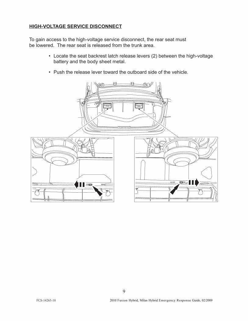
HIGH-VOLTAGE SERVICE DISCONNECT
To gain access to the high-voltage service disconnect, the rear seat mustbe lowered. The rear seat is released from the trunk area.
• Locate the seat backrest latch release levers (2) between the high-voltagebattery and the body sheet metal.
• Push the release lever toward the outboard side of the vehicle.
FCS-14265-10
9
2010 Fusion Hybrid, Milan Hybrid Emergency Response Guide, 02/2009
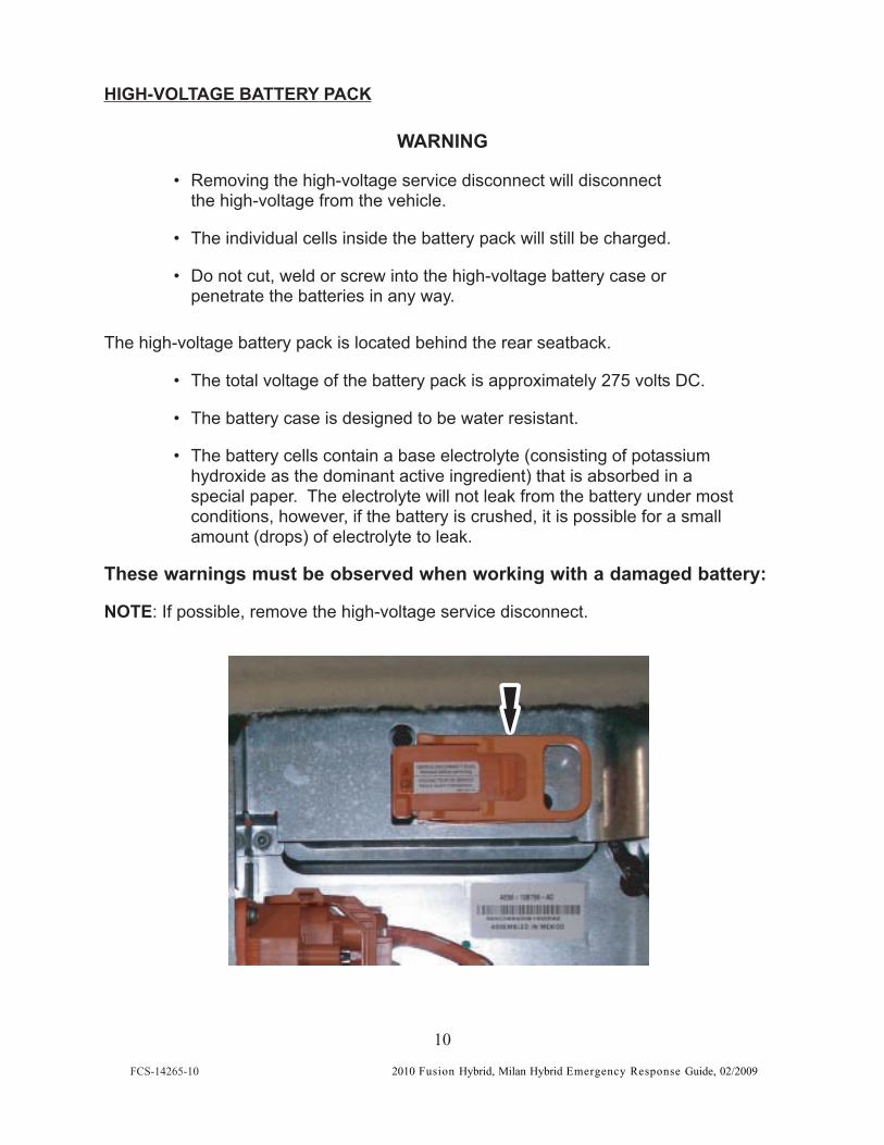
HIGH-VOLTAGE BATTERY PACK
WARNING
• Removing the high-voltage service disconnect will disconnectthe high-voltage from the vehicle.
• The individual cells inside the battery pack will still be charged.
• Do not cut, weld or screw into the high-voltage battery case orpenetrate the batteries in any way.
The high-voltage battery pack is located behind the rear seatback.
• The total voltage of the battery pack is approximately 275 volts DC.
• The battery case is designed to be water resistant.
• The battery cells contain a base electrolyte (consisting of potassiumhydroxide as the dominant active ingredient) that is absorbed in aspecial paper. The electrolyte will not leak from the battery under mostconditions, however, if the battery is crushed, it is possible for a smallamount (drops) of electrolyte to leak.
These warnings must be observed when working with a damaged battery:
NOTE: If possible, remove the high-voltage service disconnect.
FCS-14265-10
10
2010 Fusion Hybrid, Milan Hybrid Emergency Response Guide, 02/2009
1. Exposure to electrolyte could cause skin/eye irritation and/or burns. If exposed,rinse with large amounts of water until the soapy feel is gone. Personal ProtectiveEquipment (PPE) such as splash shield or safety goggles, gloves (latex, rubber orNitrile), an apron or overcoat suitable to protect against alkaline and rubber bootsare required when handling damaged batteries. Fold-down helmet shields are notacceptable for acid or alkaline spills.
2. If the battery is exposed to intense heat, it is possible that hydrogen could bereleased from the battery. Appropriate precautions should be taken to make surethe area is properly ventilated, such as, opening the vehicle windows or doors.
APPROACHING A DAMAGED HIGH-VOLTAGE VEHICLE
1. FOLLOW EXISTING TRAINING AND INCIDENT COMMANDER DIRECTION.• This guide provides only supplemental information as it pertains to the
Fusion Hybrid and Milan Hybrid vehicles. The same rules apply whenapproaching any potential high-voltage situation. Always follow yourhigh-voltage safety training. Some precautions to be taken in anyhigh-voltage situation include:— Remove all jewelry (watches, necklaces and earrings). Metal objects
are conductors of electricity.— Wear the necessary PPEs (high-voltage rubber gloves, face shield,
insulated boots, protective raincoat or apron).
— Bring the following equipment:
• Class ABC powder-type fire extinguisher
• A non-conductive object – about 1.5 m (5 ft) long – used to safely pushsomeone away from the vehicle if they accidentally come in contactwith high-voltage.
2. APPROACHING A DAMAGED VEHICLE.
• Disable the high-voltage electrical system using as many of the followingsteps as possible:
— Secure the vehicle — place the shift lever into the PARK position.Remove the ignition key. Block the wheels, if necessary. Removing theignition key or turning the key to the OFF position will disconnect thehigh-voltage system.
— Disconnect the negative cable from the 12-volt battery – this will alsodisable the high-voltage system.
— If possible, remove the high-voltage service disconnect (See Page 9).
FCS-14265-10
11
2010 Fusion Hybrid, Milan Hybrid Emergency Response Guide, 02/2009
SPECIAL NOTES
• If the vehicle is on fire, use a Class ABC powder-type extinguisher to containand smother the flames. If water is being used, large amounts of water willbe required (e.g., from a fire hydrant) to extinguish the flames.
• If the vehicle has any exposed cables, make sure to wear high-voltagerubber gloves and other protective clothing. Do not touch any broken ordamaged high-voltage orange cables. Treat severed cables as if theycontain high voltage.
• If the vehicle is submerged in water, do not touch any high-voltagecomponents or orange cables while extricating the occupant(s). Do notremove the vehicle until you are sure the high-voltage battery is completelydischarged. A submerged high-voltage battery may produce a fizzing orbubbling reaction. The high-voltage battery will be discharged when thefizzing or bubbling has completely stopped.
3. IF THE HIGH-VOLTAGE BATTERY CASE HAS BEEN RUPTURED.
• Just like any other battery, hose the area down with large amounts of water.
4. MOVING DAMAGED VEHICLES — WRECKER DRIVERS.
• Turn the vehicle ignition key to the ACCESSORY position to releasethe locking steering wheel.
• If possible, remove the high-voltage service disconnect.
• Follow the guidelines in the Wrecker Towing Manual.
— Front Tow: Wheel Lift (FWD)
— Rear Tow: Wheel Lift with Dolly (FWD)
— Flat bed: Front and Rear
5. SPECIAL NOTE TO SALVAGE YARDS.
• If a vehicle with a high-voltage battery is to be scrapped, the high-voltagebattery must be disposed of following all local, state/provincial and federalguidelines.
FCS-14265-10
12
2010 Fusion Hybrid, Milan Hybrid Emergency Response Guide, 02/2009