Embed Size (px)
Citation preview
Diagnostic Flow Charts Pg 1 of 10 http://www.autotap.com
Diagnostic Flow Charts... Do They Always Work?
Technical article by: Bruce Bonebrake, Managing Editor at BAT Auto
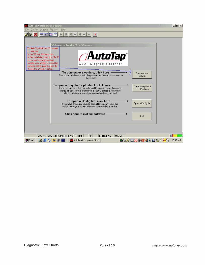
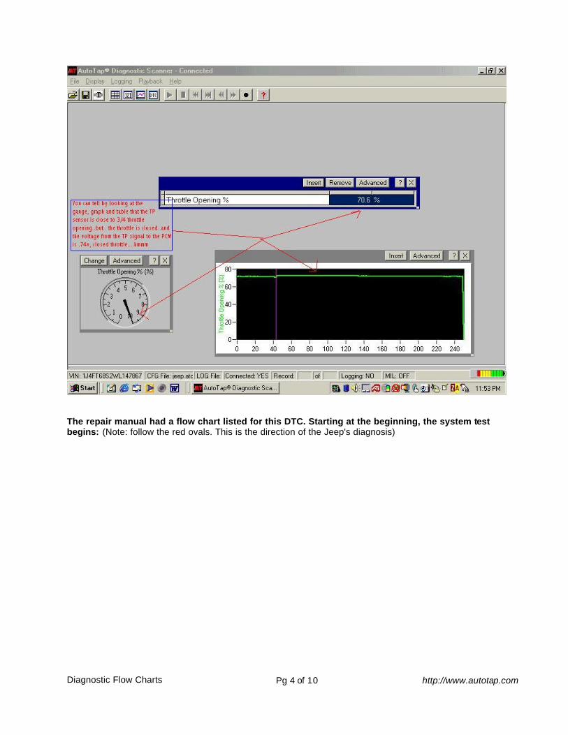
Well, you know the problem area, now what? You turn to your repair information and there is a diagnostic flow chart for the problem. Great!! Following the flow chart and going from "branch to branch" (sometimes referred to as a trouble tree chart), you come to the end of the diagnosis and staring you in the face are the words you dread to see... "Replace the PCM (Powertrain Control Module) and recheck." You look at the words in total disbelief and just can't bring yourself to this end result. You are hesitant, and for GOOD reason!! What if you buy a replacement PCM and the problem is still there? Maybe you have been faced with this dilemma before and the experience still haunts you to this day. The first question you may have is "How can the flow chart be wrong and misleading?" Well, maybe this article will shed some light on that question. It seems that I get more than my fair share of "nightmare problems" at my shop, and the one in this article I felt I just had to share with you. The day started like any other, the first appointment on the book was a 1998 Jeep Cherokee 4.0L six cylinder with the Check Engine light on and a severe hesitation. At the same time, I was performing an equipment review on AutoTap's OBD II Scanner for PC's. Great timing!! I connected the AutoTap OBD II scanner, and found that there were two stored DTC's: PO123...Throttle/Pedal Position Sensor/Switch A Circuit High Input. PO700...Transmission Control System Malfunction After reviewing the vehicle's wiring diagram, the PO700 was most likely set due to the PO123 DTC since the signal wire from the TP sensor goes to both the PCM and the TCM. By looking at the TP sensor output on the AutoTap system, it was obvious that I indeed had a problem with the TP circuit:
Diagnostic Flow Charts Pg 2 of 10 http://www.autotap.com

Diagnostic Flow Charts Pg 3 of 10 http://www.autotap.com
Diagnostic Flow Charts Pg 4 of 10 http://www.autotap.com
The repair manual had a flow chart listed for this DTC. Starting at the beginning, the system test begins: (Note: follow the red ovals. This is the direction of the Jeep's diagnosis)

Diagnostic Flow Charts Pg 5 of 10 http://www.autotap.com

Diagnostic Flow Charts Pg 6 of 10 http://www.autotap.com
Well, the flow chart diagnosis has been completed and the final result is a defective PCM. I just had a strange feeling and I just cannot seem to accept that. I work on a lot of these vehicles and I have never had to replace the PCM. As luck would have it, one of my own vehicles is the identical twin to this vehicle. Same year, make model, engine, everything right down to the color!! Since it was only a matter of four screws and three connectors and I decided to try my PCM on the problem vehicle. Just as my feeling had told me, the other PCM made no difference, the exact same problem. I even connected the computer from the problem vehicle to mine, no problems at all, the PCM worked perfectly. Well, luckily, I only lost about 20 minutes of my time, and at the chance that I could have saved the customer the expense of further diagnosis, it was time well spent. So what happened? What went wrong? The diagnostic trouble chart was carefully followed and yet the end result was incorrect? Was the flow chart misleading? Absolutely NOT, one thing to KEEP IN MIND when following the flow charts is that the "MOST LIKELY" cause will be shown. There is no way to know exactly what fails from one case to another. I don't fault the information at all, as a matter of fact, even though the problem was not yet known, I do know, by following the flow chart, what areas are correct. So, there you have it, not every example will be listed as the end result when using a diagnostic flow chart. Thanks for reading my article!! .... .... .... .... OH, I guess you’re curious what I found wrong with the Jeep? (grin) If so… read on.... Well, I know what is reading correctly and I know now that I have an unusual problem on my hands. I decided to concentrate on all of the circuits at the PCM. There are three connectors and first I started with the TP signal wire (ORG/DK BLU) at the PCM connector and was curious what the voltage was from the TP sensor to the PCM is with everything connected and the Ignition on. The sensor voltage was .52Volts from the TP sensor to the PCM...normal. And while watching the voltage and operating the throttle, the voltage changed smoothly and gradually...again, normal. So the TP sensor was operating correctly but for some reason the PCM was changing the reading. One by one I checked the PCM circuits. First the Grounds and the Power circuits... all ok. Finally, on the last connector, I found something odd. The "Cruise Control Switch In" circuit to the PCM was reading 12Volts, and it should have been 0.00Volts. Then I found that the circuit was still reading 12Volts with the Ignition OFF. Hmmmmm... Look at the pictures below of the circuit:
Diagnostic Flow Charts Pg 7 of 10 http://www.autotap.com
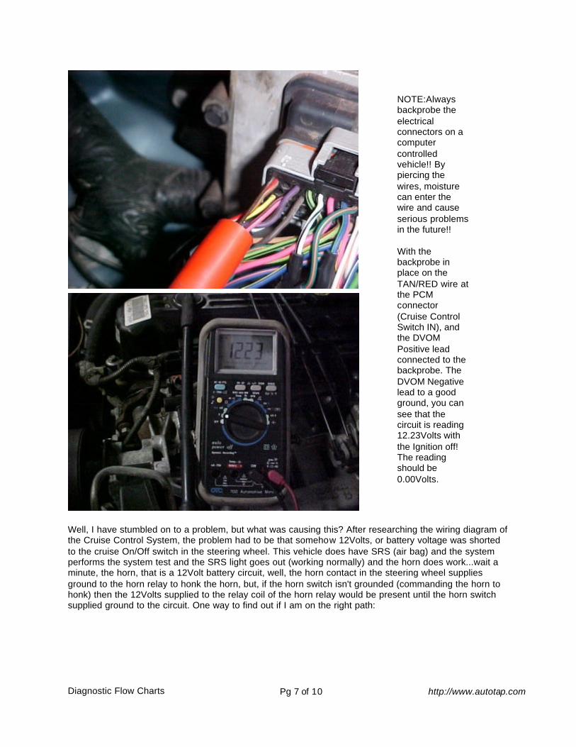
NOTE:Always backprobe the electrical connectors on a computer controlled vehicle!! By piercing the wires, moisture can enter the wire and cause serious problems in the future!! With the backprobe in place on the TAN/RED wire at the PCM connector (Cruise Control Switch IN), and the DVOM Positive lead connected to the backprobe. The DVOM Negative lead to a good ground, you can see that the circuit is reading 12.23Volts with the Ignition off! The reading should be 0.00Volts.
Well, I have stumbled on to a problem, but what was causing this? After researching the wiring diagram of the Cruise Control System, the problem had to be that somehow 12Volts, or battery voltage was shorted to the cruise On/Off switch in the steering wheel. This vehicle does have SRS (air bag) and the system performs the system test and the SRS light goes out (working normally) and the horn does work...wait a minute, the horn, that is a 12Volt battery circuit, well, the horn contact in the steering wheel supplies ground to the horn relay to honk the horn, but, if the horn switch isn't grounded (commanding the horn to honk) then the 12Volts supplied to the relay coil of the horn relay would be present until the horn switch supplied ground to the circuit. One way to find out if I am on the right path:
Diagnostic Flow Charts Pg 8 of 10 http://www.autotap.com
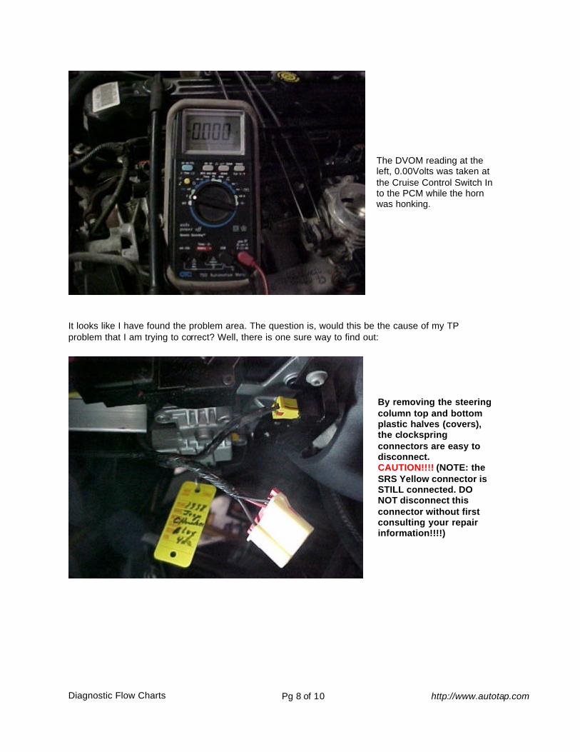
The DVOM reading at the left, 0.00Volts was taken at the Cruise Control Switch In to the PCM while the horn was honking.
It looks like I have found the problem area. The question is, would this be the cause of my TP problem that I am trying to correct? Well, there is one sure way to find out:
By removing the steering column top and bottom plastic halves (covers), the clockspring connectors are easy to disconnect. CAUTION!!!! (NOTE: the SRS Yellow connector is STILL connected. DO NOT disconnect this connector without first consulting your repair information!!!!)
Diagnostic Flow Charts Pg 9 of 10 http://www.autotap.com
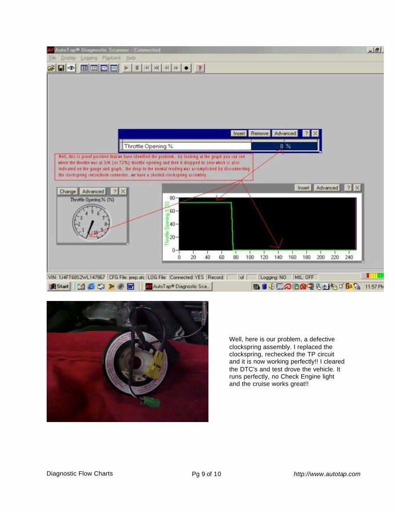
Well, here is our problem, a defective clockspring assembly. I replaced the clockspring, rechecked the TP circuit and it is now working perfectly!! I cleared the DTC's and test drove the vehicle. It runs perfectly, no Check Engine light and the cruise works great!!

Diagnostic Flow Charts Pg 10 of 10 http://www.autotap.com
After finding the cause of the problem in our Jeep, it is easy to see that there is no way the Diagnostic Flow Chart could have lead us to the cause of the problem. This was a very odd set of circumstances that caused our fault. Just remember when using the flow charts, if you come to a conclusion that you are unsure of, perform any additional testing that you can to be proof positive that the conclusion is indeed correct for the problem you are working on. Thank you for reading my article!! I want to give a very special thanks to the folks listed below:
Your feedback is GREATLY appreciated!! Please email your comments to: [email protected]
©Copyright 2001/2002 batauto.com
AutoTap – OBDII Automotive Diagnostic Tool http://www.autotap.com