Embed Size (px)
Citation preview
Vehicle CAN Bus Interface
RLVBCAN01_ManualRevision 2.0 Page 1 of 15
Vehicle CAN Bus Interface RLVBCAN01
Instruction Manual
Vehicle CAN Bus Interface
RLVBCAN01_ManualRevision 2.0 Page 2 of 15
Contents Contents ..................................................................................................................................... 2 Introduction ................................................................................................................................. 3 Key features................................................................................................................................ 3 Parts supplied with RLVBCAN01 ............................................................................................... 3
Optional accessories ............................................................................................................. 3 Specification ............................................................................................................................... 4 Introduction to CAN .................................................................................................................... 5 Connection of CAN01 to VBOX .................................................................................................. 6 Setup .......................................................................................................................................... 7
Setting up the CAN01 and enabling for logging by VBOX .................................................... 7 Serial Data ............................................................................................................................. 9 Descriptions for the signal parameters ................................................................................ 10
Data formats used in CAN ........................................................................................................11 Creating a CAN database .........................................................................................................12 Connector Assignments ...........................................................................................................13
Connector 1 – CAN/POWER IN .......................................................................................... 13 Connector 2 – CAN/POWER OUT ...................................................................................... 13 CONNECTOR 3 - Firmware Upgrade ................................................................................ 13 CONNECTOR 4 - Vehicle CAN Bus ................................................................................... 13 Cable RLVBCAB19 LEMO to 9 Way D ............................................................................... 14
Contact details ..........................................................................................................................14 Module Dimensions ..................................................................................................................15 Document updates ...................................................................................................................15
Vehicle CAN Bus Interface
RLVBCAN01_ManualRevision 2.0 Page 3 of 15
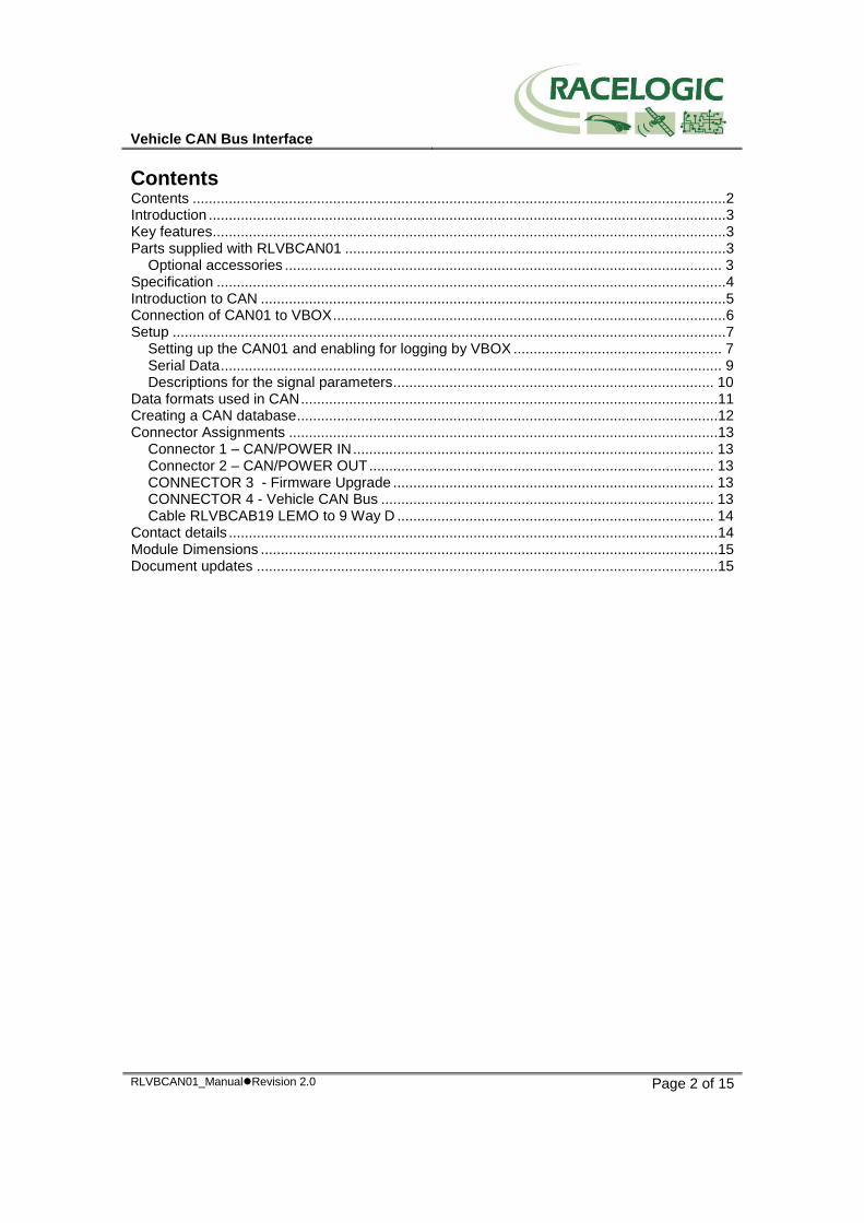
Introduction The RLVBCAN01 is designed to allow logging of vehicle CAN bus data by the Racelogic VBOX. Acting as a gateway, it collects user defined CAN messages from the vehicle bus and transfers them to the VBOX. Transfer of VBOX data to the vehicle bus is blocked to prevent unnecessary bus loading. The CAN01 also allows CAN data to be scaled and offset before it is sent to the VBOX to provide real data values in the VBOX log file.
Key features 250Kbit, 500Kbit & 1Mbit CAN rates Up to 8 separate CAN parameters Scale & offset data to record real values Blocks VBOX data from vehicle CAN bus Optional vehicle data sets available on request
Parts supplied with RLVBCAN01 1 x RLVBCAN01 Vehicle CAN interface (VCI) 1 x RLVBCAB06 Connection cable to VBOX II. 1 x RLVBCAB19 9 way Sub D terminal to LEMO.
Optional accessories
RLVBCAB01 Serial connection cable for stand-alone configuration. RLVBCAB20 OBD-II to 9 way D-sub CAN interface cable (note: not all vehicles have CAN
available on the OBD connector) RLVBACSxxx Vehicle CAN data sets. Contact Racelogic for details of specific data.
Vehicle CAN Bus Interface
RLVBCAN01_ManualRevision 2.0 Page 4 of 15
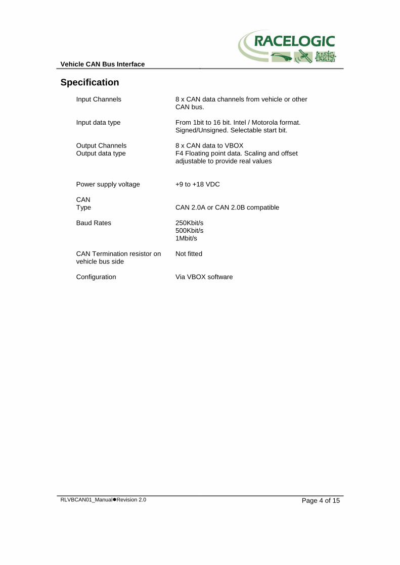
Specification
Input Channels 8 x CAN data channels from vehicle or other CAN bus.
Input data type From 1bit to 16 bit. Intel / Motorola format. Signed/Unsigned. Selectable start bit.
Output Channels 8 x CAN data to VBOX Output data type F4 Floating point data. Scaling and offset
adjustable to provide real values Power supply voltage +9 to +18 VDC CAN Type Baud Rates
CAN 2.0A or CAN 2.0B compatible 250Kbit/s 500Kbit/s 1Mbit/s
CAN Termination resistor on vehicle bus side
Not fitted
Configuration Via VBOX software
Vehicle CAN Bus Interface
RLVBCAN01_ManualRevision 2.0 Page 5 of 15
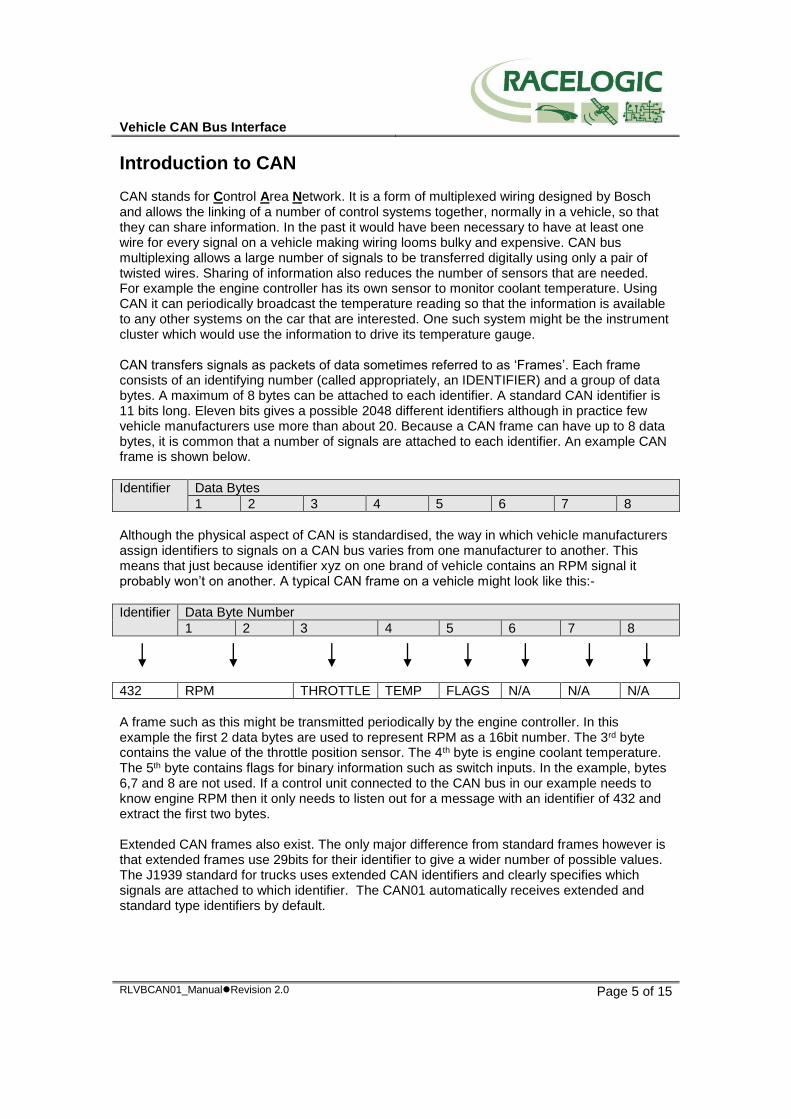
Introduction to CAN CAN stands for Control Area Network. It is a form of multiplexed wiring designed by Bosch and allows the linking of a number of control systems together, normally in a vehicle, so that they can share information. In the past it would have been necessary to have at least one wire for every signal on a vehicle making wiring looms bulky and expensive. CAN bus multiplexing allows a large number of signals to be transferred digitally using only a pair of twisted wires. Sharing of information also reduces the number of sensors that are needed. For example the engine controller has its own sensor to monitor coolant temperature. Using CAN it can periodically broadcast the temperature reading so that the information is available to any other systems on the car that are interested. One such system might be the instrument cluster which would use the information to drive its temperature gauge. CAN transfers signals as packets of data sometimes referred to as ‘Frames’. Each frame consists of an identifying number (called appropriately, an IDENTIFIER) and a group of data bytes. A maximum of 8 bytes can be attached to each identifier. A standard CAN identifier is 11 bits long. Eleven bits gives a possible 2048 different identifiers although in practice few vehicle manufacturers use more than about 20. Because a CAN frame can have up to 8 data bytes, it is common that a number of signals are attached to each identifier. An example CAN frame is shown below.
Identifier Data Bytes
1 2 3 4 5 6 7 8
Although the physical aspect of CAN is standardised, the way in which vehicle manufacturers assign identifiers to signals on a CAN bus varies from one manufacturer to another. This means that just because identifier xyz on one brand of vehicle contains an RPM signal it probably won’t on another. A typical CAN frame on a vehicle might look like this:-
Identifier Data Byte Number
1 2 3 4 5 6 7 8
432 RPM THROTTLE TEMP FLAGS N/A N/A N/A
A frame such as this might be transmitted periodically by the engine controller. In this example the first 2 data bytes are used to represent RPM as a 16bit number. The 3rd byte contains the value of the throttle position sensor. The 4th byte is engine coolant temperature. The 5th byte contains flags for binary information such as switch inputs. In the example, bytes 6,7 and 8 are not used. If a control unit connected to the CAN bus in our example needs to know engine RPM then it only needs to listen out for a message with an identifier of 432 and extract the first two bytes. Extended CAN frames also exist. The only major difference from standard frames however is that extended frames use 29bits for their identifier to give a wider number of possible values. The J1939 standard for trucks uses extended CAN identifiers and clearly specifies which signals are attached to which identifier. The CAN01 automatically receives extended and standard type identifiers by default.
Vehicle CAN Bus Interface
RLVBCAN01_ManualRevision 2.0 Page 6 of 15
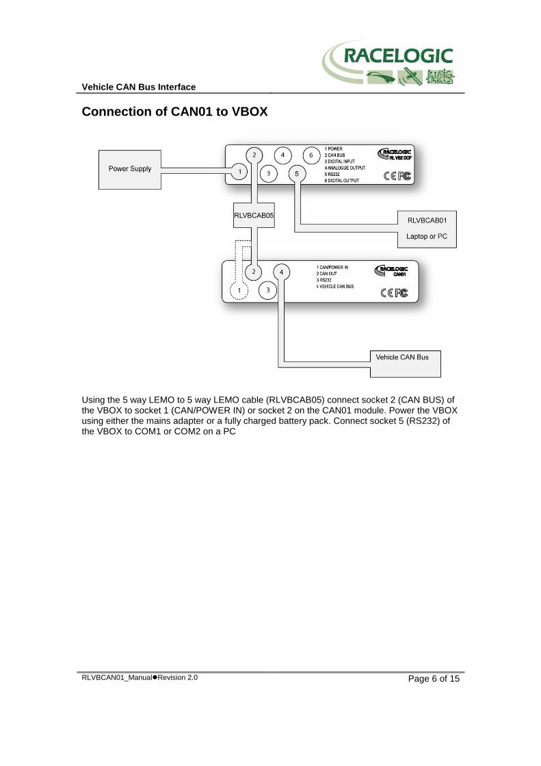
Connection of CAN01 to VBOX
Using the 5 way LEMO to 5 way LEMO cable (RLVBCAB05) connect socket 2 (CAN BUS) of the VBOX to socket 1 (CAN/POWER IN) or socket 2 on the CAN01 module. Power the VBOX using either the mains adapter or a fully charged battery pack. Connect socket 5 (RS232) of the VBOX to COM1 or COM2 on a PC
Vehicle CAN Bus Interface
RLVBCAN01_ManualRevision 2.0 Page 7 of 15
Setup
Setting up the CAN01 and enabling for logging by VBOX
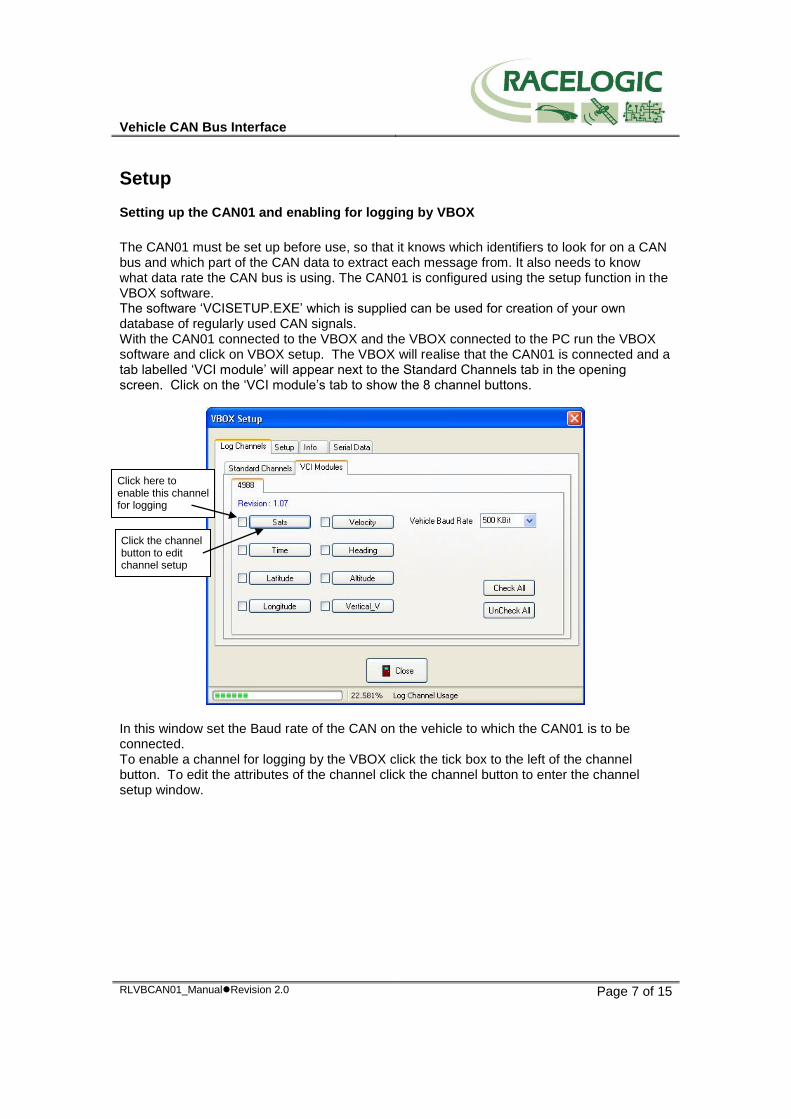
The CAN01 must be set up before use, so that it knows which identifiers to look for on a CAN bus and which part of the CAN data to extract each message from. It also needs to know what data rate the CAN bus is using. The CAN01 is configured using the setup function in the VBOX software. The software ‘VCISETUP.EXE’ which is supplied can be used for creation of your own database of regularly used CAN signals. With the CAN01 connected to the VBOX and the VBOX connected to the PC run the VBOX software and click on VBOX setup. The VBOX will realise that the CAN01 is connected and a tab labelled ‘VCI module’ will appear next to the Standard Channels tab in the opening screen. Click on the ‘VCI module’s tab to show the 8 channel buttons.
In this window set the Baud rate of the CAN on the vehicle to which the CAN01 is to be connected. To enable a channel for logging by the VBOX click the tick box to the left of the channel button. To edit the attributes of the channel click the channel button to enter the channel setup window.
Click here to enable this channel for logging
Click the channel button to edit channel setup
Vehicle CAN Bus Interface
RLVBCAN01_ManualRevision 2.0 Page 8 of 15
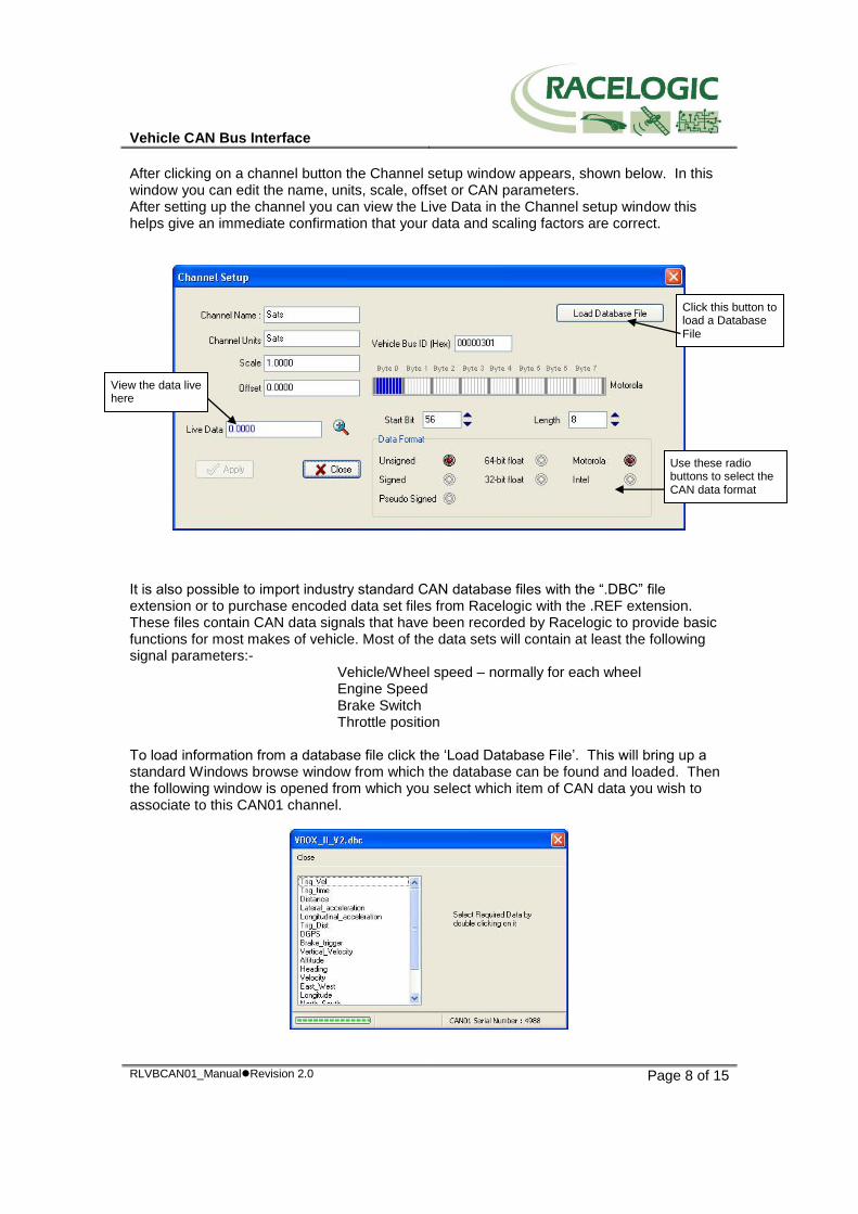
After clicking on a channel button the Channel setup window appears, shown below. In this window you can edit the name, units, scale, offset or CAN parameters. After setting up the channel you can view the Live Data in the Channel setup window this helps give an immediate confirmation that your data and scaling factors are correct.
It is also possible to import industry standard CAN database files with the “.DBC” file extension or to purchase encoded data set files from Racelogic with the .REF extension. These files contain CAN data signals that have been recorded by Racelogic to provide basic functions for most makes of vehicle. Most of the data sets will contain at least the following signal parameters:- Vehicle/Wheel speed – normally for each wheel Engine Speed Brake Switch Throttle position To load information from a database file click the ‘Load Database File’. This will bring up a standard Windows browse window from which the database can be found and loaded. Then the following window is opened from which you select which item of CAN data you wish to associate to this CAN01 channel.
Use these radio buttons to select the CAN data format
Click this button to load a Database File
View the data live here
Vehicle CAN Bus Interface
RLVBCAN01_ManualRevision 2.0 Page 9 of 15
Serial Data
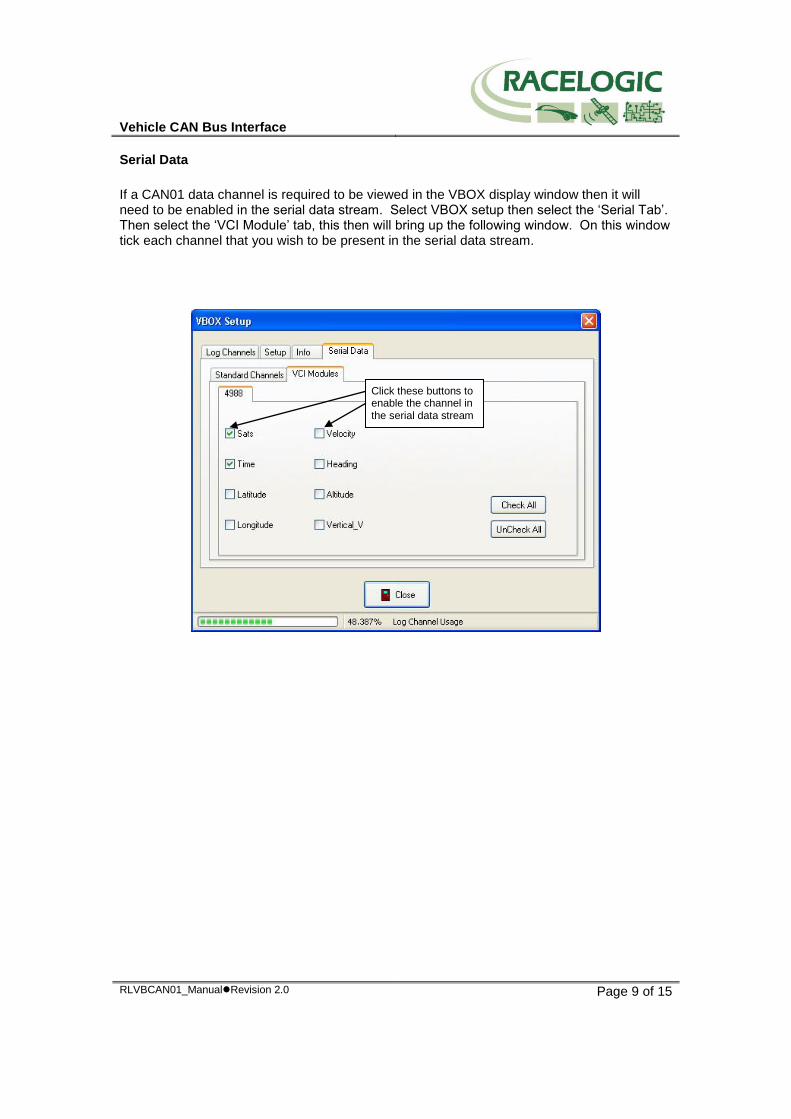
If a CAN01 data channel is required to be viewed in the VBOX display window then it will need to be enabled in the serial data stream. Select VBOX setup then select the ‘Serial Tab’. Then select the ‘VCI Module’ tab, this then will bring up the following window. On this window tick each channel that you wish to be present in the serial data stream.
Click these buttons to enable the channel in the serial data stream
Vehicle CAN Bus Interface
RLVBCAN01_ManualRevision 2.0 Page 10 of 15
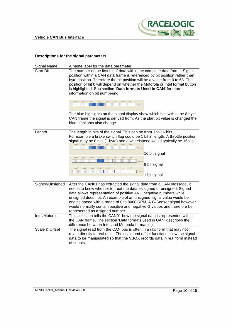
Descriptions for the signal parameters
Signal Name A name label for the data parameter
Start Bit The number of the first bit of data within the complete data frame. Signal position within a CAN data frame is referenced by bit position rather than byte position. Therefore the bit position will be a value from 0 to 63. The position of bit 0 will depend on whether the Motorola or Intel format button is highlighted. See section ‘Data formats Used in CAN’ for more information on bit numbering.
The blue highlights on the signal display show which bits within the 8 byte CAN frame the signal is derived from. As the start bit value is changed the blue highlights also change.
Length The length in bits of the signal. This can be from 1 to 16 bits. For example a brake switch flag could be 1 bit in length. A throttle position signal may be 8 bits (1 byte) and a wheelspeed would typically be 16bits.
16 bit signal
8 bit signal
1 bit signal
Signed/Unsigned After the CAN01 has extracted the signal data from a CAN message, it needs to know whether to treat the data as signed or unsigned. Signed data allows representation of positive AND negative numbers while unsigned does not. An example of an unsigned signal value would be engine speed with a range of 0 to 8000 RPM. A G-Sensor signal however would normally contain positive and negative G values and therefore be represented as a signed number.
Intel/Motorola This selection tells the CAN01 how the signal data is represented within the CAN frame. The section ‘Data formats used in CAN’ describes the difference between Intel and Motorola formatting.
Scale & Offset The signal read from the CAN bus is often in a raw form that may not relate directly to real units. The scale and offset functions allow the signal data to be manipulated so that the VBOX records data in real form instead of counts.
Vehicle CAN Bus Interface
RLVBCAN01_ManualRevision 2.0 Page 11 of 15
Data formats used in CAN To further complicate the way in which data is represented in a CAN message there are two main methods used by manufacturers for referring to the bit or byte order in a message. Example 1
Identifier Byte 1 Byte 2 Byte 3 Byte 4 Byte 5 Byte 6 Byte 7 Byte 8
298 High byte
Low Byte
Example 2
Identifier Byte 1 Byte 2 Byte 3 Byte 4 Byte 5 Byte 6 Byte 7 Byte 8
298 Low byte
High Byte
The example above shows 2 CAN messages with the same identifier. In both examples, a 16bit number is stored in byte positions 1 and 2 of the CAN frame. In Example 1 the 16bit number is stored so that the high byte is stored in position 1 and the low byte in position 2 of the frame. Example 2 shows that the 16bit value can also be stored in a low byte then high byte format. The two different ways of storing data are generally referred to as Intel and Motorola types for historic reasons. Intel processors use a "Little Endian" byte order. Motorola processors use a "Big Endian" byte order. Intel format or "Little Endian" means that the LSB of the number is stored in memory at the lowest address, and the MSB at the highest address. ie. the little end comes first. Motorola format or "Big Endian" means that the MSB of the number is stored in memory at the lowest address, and the LSB at the highest address. ie. the big end comes first. For example, a 32bit or 4 byte LongInteger using Intel format will be stored as Byte0 Byte1 Byte2 Byte3 and Byte3 Byte2 Byte1 Byte0 using Motorola Format.
Bit numbering of CAN Data stored in Motorola format Byte number
1 2 3 4 5 6 7 8
Bit number
63……56 55……48 47……40 39……32 31……24 23……16 15……8 7……0
Bit numbering of CAN Data stored in Intel format Byte number
1 2 3 4 5 6 7 8
Bit number
7……0 15……8 23……16 31……24 39……32 47……40 55……48 63……49
Some vehicle manufacturers use Intel format in their CAN frames and others will use Motorola format. Therefore a 16 bit engine speed signal, for example, could be stored High byte 1st , low byte 2nd or Low byte 1st , High byte 2nd within a CAN frame depending on the vehicle make.
Vehicle CAN Bus Interface
RLVBCAN01_ManualRevision 2.0 Page 12 of 15
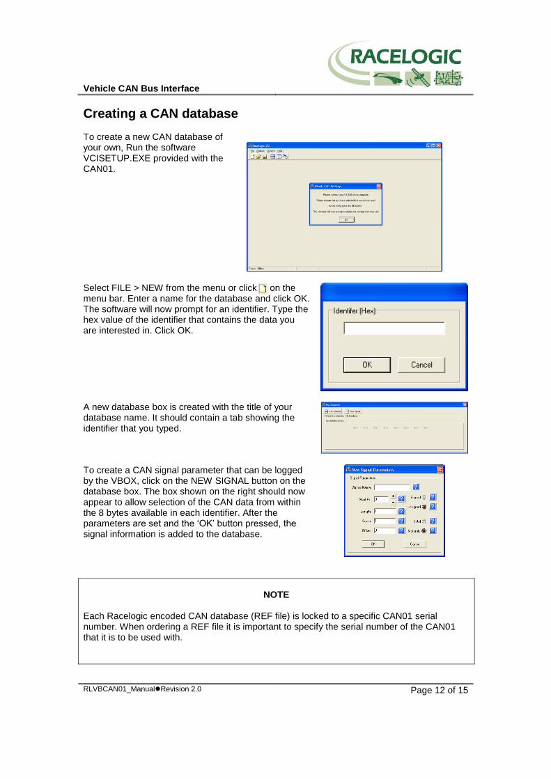
Creating a CAN database To create a new CAN database of your own, Run the software VCISETUP.EXE provided with the CAN01.
Select FILE > NEW from the menu or click on the menu bar. Enter a name for the database and click OK. The software will now prompt for an identifier. Type the hex value of the identifier that contains the data you are interested in. Click OK.
A new database box is created with the title of your database name. It should contain a tab showing the identifier that you typed.
To create a CAN signal parameter that can be logged by the VBOX, click on the NEW SIGNAL button on the database box. The box shown on the right should now appear to allow selection of the CAN data from within the 8 bytes available in each identifier. After the parameters are set and the ‘OK’ button pressed, the signal information is added to the database.
NOTE
Each Racelogic encoded CAN database (REF file) is locked to a specific CAN01 serial number. When ordering a REF file it is important to specify the serial number of the CAN01 that it is to be used with.
Vehicle CAN Bus Interface
RLVBCAN01_ManualRevision 2.0 Page 13 of 15
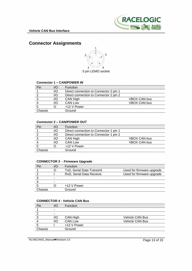
Connector Assignments
5 pin LEMO socket
Connector 1 – CAN/POWER IN
Pin I/O Function
1 I/O Direct connection to Connector 2 pin 1
2 I/O Direct connection to Connector 2 pin 2
3 I/O CAN High VBOX CAN bus
4 I/O CAN Low VBOX CAN bus
5 O +12 V Power
Chassis Ground
Connector 2 – CAN/POWER OUT
Pin I/O Function
1 I/O Direct connection to Connector 1 pin 1
2 I/O Direct connection to Connector 1 pin 2
3 I/O CAN High VBOX CAN bus
4 I/O CAN Low VBOX CAN bus
5 O +12 V Power
Chassis Ground
CONNECTOR 3 - Firmware Upgrade
Pin I/O Function
1 O TxD, Serial Data Transmit Used for firmware upgrade
2 I RxD, Serial Data Receive Used for firmware upgrade
3 -
4 -
5 O +12 V Power
Chassis Ground
CONNECTOR 4 - Vehicle CAN Bus
Pin I/O Function
1 -
2 -
3 I/O CAN High Vehicle CAN Bus
4 I/O CAN Low Vehicle CAN Bus
5 I +12 V Power
Chassis Ground
Vehicle CAN Bus Interface
RLVBCAN01_ManualRevision 2.0 Page 14 of 15
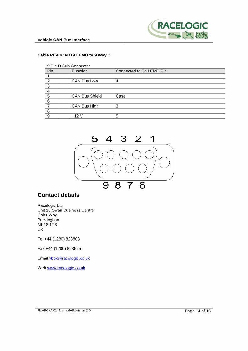
Cable RLVBCAB19 LEMO to 9 Way D
9 Pin D-Sub Connector
Pin Function Connected to To LEMO Pin
1
2 CAN Bus Low 4
3
4
5 CAN Bus Shield Case
6
7 CAN Bus High 3
8
9 +12 V 5
Contact details Racelogic Ltd Unit 10 Swan Business Centre Osier Way Buckingham MK18 1TB UK Tel +44 (1280) 823803 Fax +44 (1280) 823595 Email [email protected] Web www.racelogic.co.uk
Vehicle CAN Bus Interface
RLVBCAN01_ManualRevision 2.0 Page 15 of 15
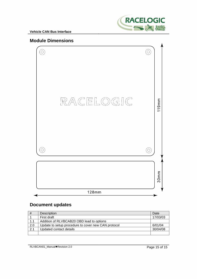
Module Dimensions
Document updates
# Description Date
1 First draft 17/03/03
1.1 Addition of RLVBCAB20 OBD lead to options
2.0 Update to setup procedure to cover new CAN protocol 6/01/04
2.1 Updated contact details 30/04/08


![PROFIsafe bus interface, PROFIsafe [BU 2800]](https://img.pdfslide.us/doc/110x75/613ca1cbf046235e845cdfe2/profisafe-bus-interface-profisafe-bu-2800.jpg)