Embed Size (px)
DESCRIPTION
L&T VEGA Multi Function Meter Manual
Citation preview

1
™ Digital Multifunction Meter
Manual for Installation and Use
Measurement of Energies Maximum Demand measurement Programmable features Separate models for Unidirectional and bidirectional measurement Suitable for 50Hz & 60Hz supply RS485 MODBUS communication Freeze mode feature
Doc. No. 4D060193 Rev. F L&T Electrical & Automation
2
Sl. No. Descriptions Page No.
1 General Details 2
2 Front Panel Details 2
3 Mechanical Dimensions 4
4 Installations 4
5 Programming the meter 5
6 Warranty & Disclaimer 6
Appendix 1: Technical Specifications 7
Appendix 2: Modbus communication details 8
Appendix 3: Addressing in Modbus 9
Appendix 4: Display Parameters 12
Appendix 5: Wiring Diagrams 15
™ is a digital panel meter for measuring electrical parameters with multiple displays in
size 96 x 96 mm. The meter is designed with high performance processor to combine measurements of
both instantaneous and cumulative values in an electrical system. The device is built with bright 7
segment displays and provides high-resolution value of various parameters. The parameters can be
scrolled up & down by front panel push buttons. The parameters like CT / PT ratings, baud rates, port
address, demand parameters etc, can set by push buttons on the front panel as well through as modbus
protocol (RS485). The programming parameters are password protected. Meter is provided with
measurement energies, MDs with programmable integration period. The unique feature of multifunction
meters, it is provided with two relays which are used to trip circuits/isolate circuits in case of predefined
fault/threshold conditions. Relays are available for specific models only.
2.1 Display & LED indications
™ Digital Multifunction Meter features with 7
segment display and LEDs for multipurpose indications.
1. Bright 7 segment Displays for displaying the
Parameters.
2. LEDs for indicating units (kilo, Mega & Giga values.)
3. LEDs for indicating Reverse of individual phases. If
any of the phases are reversed, the reversed phase is
indicated through LEDs.
4. LEDs for indicating Lead, export and communication.
2.2 Front panel push buttons:
Three push buttons Up , Down & Mode to do following functions:
1. Scrolling through display parameters
2. Programming of parameters 3. Increase /Decrease the numeric values during programming
Figure 1 Front view of Digital Multifunction Meter
2. Front Panel Details:
1. General Details:
Table of Contents
™ Digital Multifunction Meter
2.3 Programming using push buttons
Sl. No
1 Press up key and down key
mode. Meter displays PASS
2
Enter the password for user authentication (Default password is
0000). Press mode key.
programming mode once meter displays “PASS” (Password).
3 If password is correct, meter displays
programming parameter.
4 If entered password is incorrect, meter displays
return to display parameters.
5 Press up key to scroll the main menu programming pages.
6 Press mode key to select the page. Parameter default / Previous
value with first digit blinking
7 Press up key to increment the cursor position value
8 Press down key to shift cursor position to right
9
i) Press mode key to update the values. “
ii) Press up key to accept the entered value/
entered value.
10 Press up & down key to exit programming mode, meter will display
‘ESCP’ & ‘rSEt’ then followed by restart
11
For manual reset press up key and mode key simultaneously
manual scroll mode. Meter displays “rSt” and continued by display
parameter.
12
In Freeze mode, ‘Desired parameter can be monitored continuously’.
1) To enter Freeze mode:
Press ‘MODE’ key
parameter. The meter displays “
show display parameter on which it
2) To exit Freeze mode
Press ‘MODE’ key for 3sec
and continues to display scroll m
3) In case of power fail and
If the freeze mode is activated,
Displays “diSP StAY On” and then continue to show display
parameter on which it was freezed
Time out for programming mode is 1minute.After
2.4 Display Features:
On Power ON, following will be displayed sequentially: 1) All the segments of 7 segment dis 2) The firmware version 3) Display parameters The meter has a provision to scroll the display parameters automatically after ~3 seconds. The meter
enters into the manual mode by up/down key
every up & down key press respectively. If key is not pressed for ~5 minutes, it returns to auto scroll
mode. Any display parameter can be monitored continuously using
3
2.3 Programming using push buttons
Action with keys
down key simultaneously to enter to programming
PASS & 0000 with first digit blinking.
Enter the password for user authentication (Default password is
Password can be changed in the
once meter displays “PASS” (Password).
If password is correct, meter displays ACPt followed by first
programming parameter.
If entered password is incorrect, meter displays PErr & meter will
return to display parameters.
to scroll the main menu programming pages.
to select the page. Parameter default / Previous
value with first digit blinking
to increment the cursor position value
to shift cursor position to right
to update the values. “UUPd” will be displayed.
to accept the entered value/down key to skip the
to exit programming mode, meter will display
then followed by restart
For manual reset press up key and mode key simultaneously in
. Meter displays “rSt” and continued by display
Freeze mode, ‘Desired parameter can be monitored continuously’.
mode:
key continuously for 3sec to Freeze the
meter displays “diSP StAY On” and then continues to
show display parameter on which it has been freezed.
mode (To Unfreeze):
for 3sec, the meter displays “diSP StAY OFF”
display scroll mode.
case of power fail and resume:
f the freeze mode is activated, on power resume, Meter
AY On” and then continue to show display
parameter on which it was freezed.
Time out for programming mode is 1minute.After time out, meter will exit programming mode.
will be displayed sequentially: 1) All the segments of 7 segment display and all the LEDs will glow
The meter has a provision to scroll the display parameters automatically after ~3 seconds. The meter
up/down key press. In manual mode, display shall scroll up & down by
espectively. If key is not pressed for ~5 minutes, it returns to auto scroll
Any display parameter can be monitored continuously using ‘freeze mode
Display Status simultaneously to enter to programming
Pages scrolling
0/1/2/3/4/5/6/7/8/9
- - - -
” will be displayed. Step i
step ii
to exit programming mode, meter will display
Freeze mode, ‘Desired parameter can be monitored continuously’.
to Freeze the
and then continues to
AY OFF”
, Meter
AY On” and then continue to show display
time out, meter will exit programming mode.
The meter has a provision to scroll the display parameters automatically after ~3 seconds. The meter
press. In manual mode, display shall scroll up & down by
espectively. If key is not pressed for ~5 minutes, it returns to auto scroll
freeze mode’ feature.
4
Figure 2 Mechanical Dimensions
1. Dimensions of panel cut-out (92mm x 92mm) for mounting multifunction is shown in Figure 3. The connection diagram for multifunction meter is shown in figure 8, 9 &10. Care to be taken for proper connection.
2. Auxiliary voltage: Multifunction meter will power ON with
auxiliary voltage (Range from 80V to 300V AC). 3. ™ Multifunction meter is suitable for
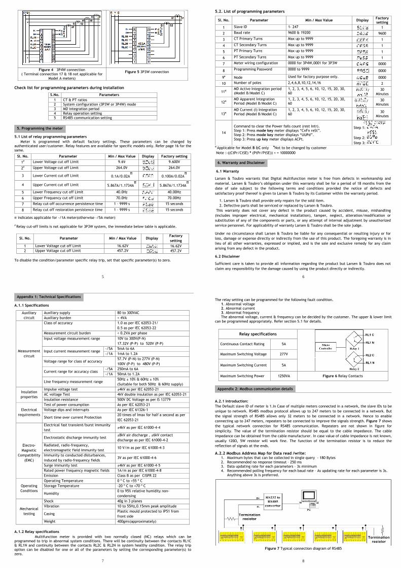
operating in star connected system and delta connected system. For connection refer Figure 4 / Figure 5. The meter should be programmed appropriately for the type of system. The default setting is for 3P4W system. To change the settings to 3P3W configuration mode, change “cnfg” setting from “0000” to “0001” in programming mode. Refer section 5.2 for details.
4. The rating of input measurement current is 5A/1A (maximum current rating is 6A/1.2A respectively).In case of higher current measurement, external Current Transformers (CT) to be used. The CT ratios need to be programmed appropriately. Refer section 5.2 for programming details. The ‘terminal S1’->’terminal S2’ is forward direction and ‘terminal S2’->’terminal S1’ is reverse direction. In case of reverse connection the meter is capable of detecting the reverse connection & will indicate through reverse LEDs. In case of Model C the forward direction is based on majority current lines. The reverse current detection logic is applicable for 3P4W connection only.
5. Maximum measuring input voltage is 300V phase to neutral. External potential transformers are to be used for high voltage measurement (HV/MV systems). The PT ratios need to be programmed in the meter suitably. Refer section 5.2 for programming details.
6. The meter is provided with two relays, to trip circuits in case of fault\threshold conditions. The setting for fault conditions can be decided by the customer. The default factory settings are available in section 5.1. Relay terminals for relay 1 is RL1C, RL1N and for relay 2 is RL2C, RL2N. Refer section A1.2(Applicable for specific models only).
7. The parameters on display can be monitored remotely using RS485 communication. The terminal connections of RS485 are D+ & D-. Modbus protocol is implemented with RS485 communication. The communication parameters need to be programmed appropriately. For connections details, settings & memory map refer section 5.1 and Appendix 2.
Figure 3 Panel cut out dimension
( 92 x 92 mm )
3. Mechanical Dimensions
4. Installations
5
Check list for programming parameters during installation
S.No. Parameters
1 CT & PT ratios
2 System configuration (3P3W or 3P4W) mode
3 MD integration period
4 Relay operation setting
5 RS485 communication setting
5.1 List of relay programming parameters
Meter is programmed with default factory settings. These parameters can be changed by authenticated user/customer. Relay features are available for specific models only. Refer page 16 for the same.
Sl. No. Parameter Min / Max Value Display Factory setting
1# Lower Voltage cut off Limit 9.6V 9.600V
2# Upper Voltage cut off Limit 264.0V 264.0V
3 Lower Current cut off Limit 0.1A/0.02Aπ
0.100A/0.02Aπ
4 Upper Current cut off Limit 5.867A/1.1734Aπ
5.867A/1.1734Aπ
5 Lower Frequency cut off Limit 40.0Hz 40.00Hz
6 Upper Frequency cut off Limit 70.0Hz 70.00Hz
7 Relay cut-off occurrence persistence time 1 – 9999 s 15 seconds
8 Relay cut off restoration persistence time 1 – 9999 s 15 seconds
π indicates applicable for -/1A meter(otherwise -/5A meter) # Relay cut-off limits is not applicable for 3P3W system, the immediate below table is applicable.
Sl. No. Parameter Min / Max Value Display Factory
setting
1 Lower Voltage cut off Limit 16.62V 16.62V
2 Upper Voltage cut off Limit 457.2V 457.2V
To disable the condition/parameter specific relay trip, set that specific parameter(s) to zero.
Figure 4 3P4W connection ( Terminal connection 17 & 18 not applicable for
Model A meters)
Figure 5 3P3W connection
5. Programming the meter
6
5.2. List of programming parameters
Sl. No. Parameter Min / Max Value Display Factory setting
1 Slave ID 1- 247 1
2 Baud rate 9600 & 19200 9600
3 CT Primary Turns Max up to 9999 1
4 CT Secondary Turns Max up to 9999 1
5 PT Primary Turns Max up to 9999 1
6 PT Secondary Turns Max up to 9999 1
7 Meter wiring configuration 0000 for 3P4W,0001 for 3P3W 0000
8 Programming Password 0000 to 9999 0000
9♦ Node Used for factory purpose only. 0000
10 Number of poles 2,4,6,8,10,12,14,16 2
11α MD Active Integration period (Model B/Model C)
1, 2, 3, 4, 5, 6, 10, 12, 15, 20, 30, 60
/
30 Minutes
12α MD Apparent Integration Period (Model B/Model C)
1, 2, 3, 4, 5, 6, 10, 12, 15, 20, 30, 60
/
30 Minutes
13α MD Current (I) Integration Period (Model B/Model C)
1, 2, 3, 4, 5, 6, 10, 12, 15, 20, 30, 60
/
30 Minutes
14
Command to clear the Power fails count (rest Intr). Step 1: Press mode key meter displays “CnFn reSt”. Step 2: Press mode key meter displays “UUPd”. Step 3: Press up key meter displays ACPt.
Step 1:
Step 2:
Step 3: α Applicable for Model B &C only
♦Not to be changed by customer
Note :-((CtPr/CtSE) * (PtPr/PtSE)) < = 10000000
6.1 Warranty
Larsen & Toubro warrants that Digital Multifunction meter is free from defects in workmanship and
material. Larsen & Toubro’s obligation under this warranty shall be for a period of 18 months from the
date of sale subject to the following terms and conditions provided the notice of defects and
satisfactory proof thereof is given to Larsen & Toubro by its Customer within the warranty period.
1. Larsen & Toubro shall provide only repairs for the sold item.
2. Defective parts shall be serviced or replaced by Larsen & Toubro.
This warranty does not cover any defect in the product caused by accident, misuse, mishandling
(includes improper electrical, mechanical installation), tamper, neglect, alteration/modification or
substitution of any of the components or parts, or any attempt of internal adjustment by unauthorized
service personnel. For applicability of warranty Larsen & Toubro shall be the sole judge.
Under no circumstance shall Larsen & Toubro be liable for any consequential or resulting injury or for
loss, damage or expense directly or indirectly from the use of this product. The foregoing warranty is in
lieu of all other warranties, expressed or implied, and is the sole and exclusive remedy for any claim
arising from any defect in the product.
6.2 Disclaimer
Sufficient care is taken to provide all information regarding the product but Larsen & Toubro does not
claim any responsibility for the damage caused by using the product directly or indirectly.
6. Warranty and Disclaimer
7
A.1.1 Specifications
Auxiliary
circuit
Auxiliary supply 80 to 300VAC
Auxiliary burden < 4VA
Measurement
circuit
Class of accuracy 1.0 as per IEC 62053-21/
0.5 as per IEC 62053-22
Measurement circuit burden < 0.2VA per phase
Input voltage measurement range 10V to 300V(P-N)
17.32V (P-P) to 520V (P-P)
Input current measurement range -/5A 5mA to 6A
-/1A 1mA to 1.2A
Voltage range for class of accuracy 57.7V (P-N) to 277V (P-N)
100V (P-P) to 480V (P-P)
Current range for accuracy class -/5A 250mA to 6A
-/1A 50mA to 1.2A
Line frequency measurement range 50Hz ± 10% & 60Hz ± 10%
(Suitable for both 50Hz & 60Hz supply)
Insulation
properties
Impulse voltage test ±4kV as per IEC 62053-21
AC voltage Test 4kV double insulation as per IEC 62053-21
Insulation resistance 500V DC Voltage as per IS 13779
Electrical
requirements
Test of power consumption As per IEC 62053-21
Voltage dips and interrupts As per IEC 61326-1
Short time over current Protection 20 times of Imax for half a second as per
IEC 62053-21
Electro-
Magnetic
Compatibility
(EMC)
Electrical fast transient/burst immunity
test ±4kV as per IEC 61000-4-4
Electrostatic discharge immunity test ±8kV air discharge , ±6kV contact
discharge as per IEC 61000-4-2
Radiated, radio-frequency,
electromagnetic field immunity test 10 V/m as per IEC 61000-4-3
Immunity to conducted disturbances,
induced by radio-frequency fields 3V as per IEC 61000-4-6
Surge immunity test ±4kV as per IEC 61000-4-5
Rated power frequency magnetic fields 1A/m as per IEC 61000-4-8
Emission Class B as per CISPR 22
Operating
Conditions
Operating Temperature 0 º C to +55 º C
Storage Temperature -20 º C to +70 º C
Humidity 0 to 95% relative humidity non-
condensing
Mechanical
testing
Shock 40g in 3 planes
Vibration 10 to 55Hz,0.15mm peak amplitude
Casing Plastic mould protected to IP51 from
front side
Weight 400gms(approximately)
A.1.2 Relay specifications
Multifunction meter is provided with two normally closed (NC) relays which can be programmed to trip in abnormal system conditions. There will be continuity between the contacts RL1C & RL1N and continuity between the contacts RL2C & RL2N in system healthy condition. The relay trip option can be disabled for one or all of the parameters by setting the corresponding parameter(s) to zero.
Appendix 1: Technical Specifications
8
The relay setting can be programmed for the following fault condition.
1. Abnormal voltage 2. Abnormal current 3. Abnormal frequency The abnormal voltage, current & frequency can be decided by the customer. The upper & lower limit
can be programmed appropriately. Refer section 5.1 for details.
A.2.1 Introduction:
The Default slave ID of meter is 1.In Case of multiple meters connected in a network, the slave IDs to be
unique to network. RS485 modbus protocol allows up to 247 meters to be connected in a network. But
the signal strength of RS485 allows only 32 meters to be connected in a network. Hence to enable
connecting up to 247 meters, repeaters to be connected to improve the signals strength. Figure 7 shows
the typical network connection for RS485 communication. Repeaters are not shown in figure for
simplicity. The value of the termination resistor should be equal to the cable impedance. The cable
impedance can be obtained from the cable manufacturer. In case value of cable impedance is not known,
usually 120Ω, 5W resistor will work fine. The function of the termination resistor is to reduce the
reflection of signals at the ends.
A.2.2 Modbus Address Map for Data read /write: 1. Maximum bytes that can be collected in single query - 180 Bytes 2. Recommended no response timeout – 250 ms 3. Data updating rate for each parameters – 3s minimum 4. Recommended polling frequency for each baud rate – As updating rate for each parameter is 3s.
Anything above 3s is preferred.
Figure 7 Typical connection diagram of RS485
Relay specifications
Continuous Contact Rating 5A
Maximum Switching Voltage 277V
Maximum Switching Current 5A
Maximum Switching Power 1250VA Figure 6 Relay Contacts
Appendix 2: Modbus communication details

9
For changing any programming parameter through modbus, first password has to be entered then
followed by the address of the parameters. Once password is entered the password is enabled for an idle
time of 2 minutes.
Address Parameters Words
40513 Password (PRIDES) for programming 3
Address Parameters Words MF
H-REGS Function code 0x06 is used for writing for following parameters
1.Relay Occurrence / Persistence Time
40337 Relay Occurrence time (in Seconds)(0001 to 9999) 1 1
40338 Relay Persistence time (in Seconds)(0001 to 9999) 1 1
2.Meter Configuration (3W/4W)
42305 0000 for 3-Phase 4-Wire Configuration
0001 for 3-Phase 3-Wire Configuration 1 1
3.Communication Parameters
41025 Meter Address (1 to 247) 1 1
41026 Baud Rate (Only following values are possible
Write 6 for 9600, 7 for 19200) 1 1
4.No of Poles
42561 No of Poles (2 to 16)(only even values) 1 1
Function code 0x10 is used for writing for following parameters
1.External CT/PT Values
41281 CT Primary (1 to 9999) 2 1
41283 CT Secondary (1 to 9999) 2 1
41285 PT Primary (1 to 9999) 2 1
41287 PT Secondary (1 to 9999) 2 1
Note:- (max. (CTprimary/CTsecondary) * (Ptprimary/Ptsecondary)) < = 10000000
2. MD Information
40769* MD1(Apparent MD) - Integration Period 1 1
40770* MD2(Active MD) - Integration Period 1 1
40849* MD3(Current MD)- Integration Period 1 1
(While programming, MD1& MD2 integration periods have to be programmed together. Individual
programming is not supported.MD3 can be programmed separately.)
3.Relay Cut off Limits
40257 Voltage Lower Limit(VL) (9.6<VL<VU) 1 0.01
40258 Voltage Upper Limit(VU) (VL<VU<264) 1 0.01
40259 Current Lower Limit(CL) (0.1<CL<CU) 1 0.01
40260 Current Upper Limit(CU) (CL<CU<5.867) 1 0.01
40261 Frequency Lower Limit(FL) (40<FL<FU) 1 0.01
40262 Frequency Upper Limit(FU) (FL<FU<70) 1 0.01
For all the above relay cut off limits, if value is programmed to zero then that parameter won’t be
considered for relay operations. (ZERO is a valid input value).All programming to be done together.
I-REGS Read Only Registers (Function Code: 0x04)
1.Instantaneous Values
30001 R Phase Voltage 2 0.01
30003 Y Phase Voltage 2 0.01
30005 B Phase Voltage 2 0.01
Appendix 3: Addressing in Modbus
10
30007 R Phase Current 2 0.001
30009 Y Phase Current 2 0.001
30011 B Phase Current 2 0.001
The Phase voltages and phase currents will be without multiplication of PT and CT ratio
respectively.
30013 Active Power R Phase 3 0.0001
30016 Active Power Y Phase 3 0.0001
30019 Active Power B Phase 3 0.0001
30022 Reactive Power R Phase 3 0.0001
30025 Reactive Power Y Phase 3 0.0001
30028 Reactive Power B Phase 3 0.0001
30031 Apparent Power R Phase 3 0.0001
30034 Apparent Power Y Phase 3 0.0001
30037 Apparent Power B Phase 3 0.0001
30040 Power Factor R Phase 2 0.001
30042 Power Factor Y Phase 2 0.001
30044 Power Factor B Phase 2 0.001
30046 Total Active Power 3 0.0001
30049 Total Reactive Power 3 0.0001
30052 Total Apparent Power 3 0.0001
30055 Total Power Factor 2 0.001
30057 Line Frequency 2 0.01
30059 RY-Line Voltage 2 0.01
30061 YB-Line Voltage 2 0.01
30063 BR-Line Voltage 2 0.01
30065 Average Phase Voltage 2 0.01
30067 Average Phase Current 2 0.001
30069** R Phase Voltage Harmonic 2 0.01
30071** Y Phase Voltage Harmonic 2 0.01
30073** B Phase Voltage Harmonic 2 0.01
30075** R Phase Current Harmonic 2 0.001
30077** Y Phase Current Harmonic 2 0.001
30079** B Phase Current Harmonic 2 0.001
30081* Phase Difference-R Voltage & Current 2 0.01
30083* Phase Difference-Y Voltage & Current 2 0.01
30085* Phase Difference-B Voltage & Current 2 0.01
30087* Voltage Unbalance R Phase 2 0.001
30089* Voltage Unbalance Y Phase 2 0.001
30091* Voltage Unbalance B Phase 2 0.001
30093* Current Unbalance R Phase 2 0.001
30095* Current Unbalance Y Phase 2 0.001
30097* Current Unbalance B Phase 2 0.001
30099* Percentage Load R Phase 2 0.01
30101* Percentage Load Y Phase 2 0.01
30103* Percentage Load B Phase 2 0.01
30105* RPM 2 1
30107* Neutral Current 2 0.001
2. Read Cumulative Energies.
31795 Import Apparent energy 3 0.01
31798 Import Active energy 3 0.01
11
31801 Import Reactive Lag energy 3 0.01
31804 Import Reactive Lead energy 3 0.01
31807** Export Apparent energy 3 0.01
31810** Export Active energy 3 0.01
31813** Export Reactive Lag energy 3 0.01
31816** Export Reactive Lead energy 3 0.01
3.Read MD
31891* MD Import Apparent 3 0.0001
31894* MD Import Active 3 0.0001
31897*** Apparent Rising Demand 3 0.0001
31897** MD Export Apparent 3 0.0001
31900*** Active Rising Demand 3 0.0001
31900** MD Export Active 3 0.0001
31903** Import Apparent Rising Demand 3 0.0001
31906** Import Active Rising Demand 3 0.0001
31909** Export Apparent Rising Demand 3 0.0001
31912** Export Active Rising Demand 3 0.0001
4.Cumulative Energy Backups
32050 Import Apparent Energy 3 0.01
32053 Import Active Energy 3 0.01
32056 Import Reactive Energy – lag 3 0.01
32059 Import Reactive Energy – lead 3 0.01
32062** Export Apparent Energy 3 0.01
32065** Export Active Energy 3 0.01
32068** Export Reactive Energy – lag 3 0.01
32071** Export Reactive Energy – lead 3 0.01
5.Read MD Backup
32146* MD Import Apparent Backup 3 0.0001
32149* MD Import Active Backup 3 0.0001
32152** MD Export Apparent Backup 3 0.0001
32155** MD Export Active Backup 3 0.0001
6.Other parameters
31537 No. of Resets 1 1
31617 Total Import Load Time (Days(1) + hr(1)) 2 1
31633 Total Power ON Time (Days(1) + hr(1) 2 1
31638** Total Export Load Time (Days(1) + hr(1) 2 1
31649 Total Import Load Time Backup (Days(1) + hr(1)) 2 1
31654** Total Export Load Time Backup (Days(1) + hr(1) 2 1
31665 Total Power Failure Count 1 1
7.Time Remaining
31681* Time Remaining kVA MD 1 1
31686***/
31683** Time Remaining kW MD 1
1
31691* Time Remaining Current MD 1 1
8.Hour MD Occurred
31697* Hour Import kVA MD Occurred 3 1
31702** Hour Import KW MD Occurred 3 1
31707** Hour Export KVA MD Occurred 3 1
31713*** Hour Import kW MD Occurred 3 1
31713** Hour Export KW MD Occurred 3 1
12
31718** Hour Current MD Occurred 3 1
31729*** Hour Current MD Occurred 3 1
9.Current MD
31745* Read Current MD 3 0.0001
31750* Read Current Rising Demand 3 0.0001
31755* Read Current MD Backup 3 0.0001
* Applicable for model B & C only. ** Applicable for model C only.
*** Applicable for model B only.
Note 1: The 3rd hexadecimal word in MODBUS is for the unit. 1-KILO, 2-MEGA, 3-GIGA. The default unit
of measurement is KILO. If the MODBUS data value is ‘*’, then multiplication factor is not applicable.
Model A & Model B are unidirectional meters and Model C is bi-directional meter.
Sl. No.
Parameter Display Line1
Display Line2
Display Line3
Display Indica-
tion
Display sequence §
A B C
1 Phase voltage U1
U1 Value U2
U2 Value U3
U3 Value R,Y,B 1 1 1
2 Line to line voltage
U12 U12 Value
U23 U23 Value
U31 U31 Value R,Y,B 2 2 2
3 Phase Current A1
A1 Value A2
A2 Value A3
A3 Value R,Y,B 3 3 3
4 Average Voltage, Average current
AU AU Value
AA AA Value
Blank R,Y,B 4 4 4
5 Neutral Current An An Value Blank 5 5
6 Line Frequency F F value Blank 5 6 6
7 Percentage Load PLd1
PLd1 Value PLd2
PLd2 Value PLd3
PLd3 Value R,Y,B 7 7
8 Voltage Unbalance Uub1
Uub1 Value Uub2
Uub2 Value Uub3
Uub3 Value R,Y,B 8 8
9 Current Unbalance Iub1
Iub1 Value Iub2
Iub2 Value Iub3
Iub3 Value R,Y,B 9 9
10 System Power factor
PF-t PF-t Value Blank 6 10 10
11 Power factor R phase
PF-1 PF-1 Value Blank 7 11 11
12 Power factor Y phase
PF-2 PF-2 Value Blank 8 12 12
13 Power factor B phase
PF-3 PF-3 Value Blank 9 13 13
14 RPM rPn rPn Value Blank 10 14 14
15 Phase Angle PA1
PA1 Value PA2
PA2 Value PA3
PA3 Value R,Y,B 15 15
16 Active Power R phase
Apr1 Apr1 value
(MSB) Apr1 value
(LSB)
11 16 16
17 Active Power Y phase
Apr2 Apr2 Value
(MSB) Apr2 value
(LSB) 12 17 17
18 Active Power B phase
Apr3 Apr3 Value
(MSB) Apr3 value
(LSB) 13 18 18
19 Total active power Pr.A Pr.A Value
(MSB) Pr.A Value
(LSB) 14 19 19
20 Apparent Power R phase
Apn1 Apn1 Value
(MSB) Apn1 Value
(LSB) 15 20 20
Appendix 4: Display Parameters
13
21 Apparent Power Y phase
Apn2 Apn2 Value
(MSB) Apn2 Value
(LSB) 16 21 21
22 Apparent Power B phase
Apn3 Apn3 Value
(MSB) Apn3 Value
(LSB) 17 22 22
23 Total apparent power
Pr.AP Pr.AP Value
(MSB) Pr.AP Value
(LSB) 18 23 23
24 Reactive Power R phase
rPr1 rPr1 value
(MSB) rPr1 value
(LSB) 19 24 24
25 Reactive Power Y phase
rPr2 rPr2 Value
(MSB) rPr2 Value
(LSB) 20 25 25
26 Reactive Power B phase
rPr3 rPr3 Value
(MSB) rPr3 Value
(LSB) 21 26 26
27 Total reactive power
Pr.r Pr.r Value
(MSB) Pr.r Value
(LSB) 22 27 27
28 MD Apparent APnd APnd Value
(MSB) APnd Value
(LSB) 28 28
29 Occurrence Time of MD Import Apparent
Days n1-d
Hours n1-h
Minutes n1-n 37 29
30 Rising MD Import Apparent
APrd APrd value
(MSB) APrd value
(LSB) 31 30
31 MD Export Apparent
EPnd EPnd value
(MSB) EPnd value
(LSB) Exp 31
32 Occurrence Time of MD Export Apparent
Days n2-d
Hours n2-h
Minutes n2-n 32
33 Rising MD Export Apparent
EPrd EPrd value
(MSB) EPrd value
(LSB) Exp 33
34
Remaining Time of MD Apparent (Import and Export)
rtn1Y / rt12 Minutes
n.xx Blank 34 34
35 MD Import Active Atnd Atnd value
(MSB) Atnd value
(LSB) 29 35
36 Occurrence Time of MD Import Active
Days n2-dY / n3-d
Hours n2-hY / n3-h
Minutes n2-nY/ n3-n
38 36
37 Rising MD Import Active
Atrd Atrd value
(MSB) Atrd value
(LSB) 32 37
38 MD Export Active
Etnd Etnd value
(MSB) Etnd value
(LSB) Exp 38
39 Occurrence Time of MD Export Active
Days n4-d
Hours n4-h
Minutes n4-n 39
40 Rising MD Export Active
Etrd Etrd value
(MSB) Etrd value
(LSB) Exp 40
41 Remaining Time of MD Active (Import and Export)
rtn2Y / rt34 Minutes
n.xx Blank 35 41
42 MD Current (I) Ind Ind Value Blank 30 42
43 Occurrence Time of MD Current
Days n3- dY / n5-d
Hours n3-hY / n5-h
Minutes n3-nY / n5-n
39 43
44 Average MD current (I)
Ird Ird value Blank 33 44
45 Remaining Time of MD Current
rtn3Y / rt5 Minutes
n.xx Blank 36 45
46 MD Import Apparent backup
APnb APnb value
(MSB) APnb value
(LSB) 40 46
14
47 MD Export Apparent backup
EPnb EPnb value
(MSB) EPnb value
(LSB) Exp 47
48 MD Import Active backup
Atnb Atnb value
(MSB) Atnb value
(LSB) 41 48
49 MD Export Active backup
Etnb Etnb value
(MSB) Etnb value
(LSB) Exp 49
50 MD Current backup
Indb Indb value
(MSB) Indb value
(LSB) 42 50
51 Import Active Energy
IAEn IAEn value
(MSB) IAEn value
(LSB) 23 43 51
52 Import reactive lag Energy
IrEL IrEL Value
(MSB) IrEL Value
(LSB) 24 44 52
53 Import reactive lead Energy
IrEL IrEL Value
(MSB) IrEL Value
(LSB) Lead 25 45 53
54 Import Apparent Energy
IAPE IAPE Value
(MSB) IAPE Value
(LSB) 26 46 54
55 Total Import load run hour Mains
trhY / trFh d.xxx h. xx 27 47 55
56 Total Power on time
tPot d.xxx h. xx 28 48 56
57 Total Power fail count
Pr FAIL Pr value
29 49 57
58 Export Active Energy
EAEn EAEn Value
(MSB) EAEn Value
(LSB) Exp 58
59 Export reactive lag Energy
ErEL ErEL value
(MSB) ErEL value
(LSB) Exp 59
60 Export reactive lead Energy
ErEL ErEL value
(MSB) ErEL value
(LSB) Lead, Exp
60
61 Export apparent Energy
EAPE EAPE Value
(MSB) EAPE Value
(LSB) Exp 61
62 Total Export load run hour Mains
Trrh d.xxx h. xx 62
63 Import Active Energy backup
IAEb IAEb value
(MSB) IAEb value
(LSB) 30 50 63
64 Import Apparent Energy backup
IAPb IAPb value
(MSB) IAPb value
(LSB) 31 51 64
65 Import Reactive Lag Energy backup
IrEb IrEb value
(MSB) IrEb value
(LSB) 32 52 65
66 Import Reactive Lead Energy backup
IrEb IrEb value
(MSB) IrEb value
(LSB) Lead 33 53 66
67 Total load run hour Backup
trhbY / trFb d.xxx h. xx 34 54 67
68 Export Active Energy backup
EAEb EAEb value
(MSB) EAEb value
(LSB) Exp 68
69 Export Apparent Energy backup
EAPb EAPb value
(MSB) EAPb value
(LSB) Exp 69
70 Export Reactive Lag Energy backup
ErEb ErEb Value
(MSB) ErEb Value
(LSB) Exp 70
71 Export Reactive Lead Energy backup
ErEb ErEb Value
(MSB) ErEb Value
(LSB) Exp, Lead
71
72 Total Export load run hour Backup
Trrb d.xxx h. xx 72
73 Phase Distortion-voltage
UH1 UH1 Value
UH2 UH2 value
UH3 UH3 Value R,Y,B 73
74 Distortion-phase Current
AH1 AH1 Value
AH2 AH2 Value
AH3 AH3 Value R,Y,B 74
75 Modbus Slave ID SL.Id SL.Id Value Blank 35 55 75
15
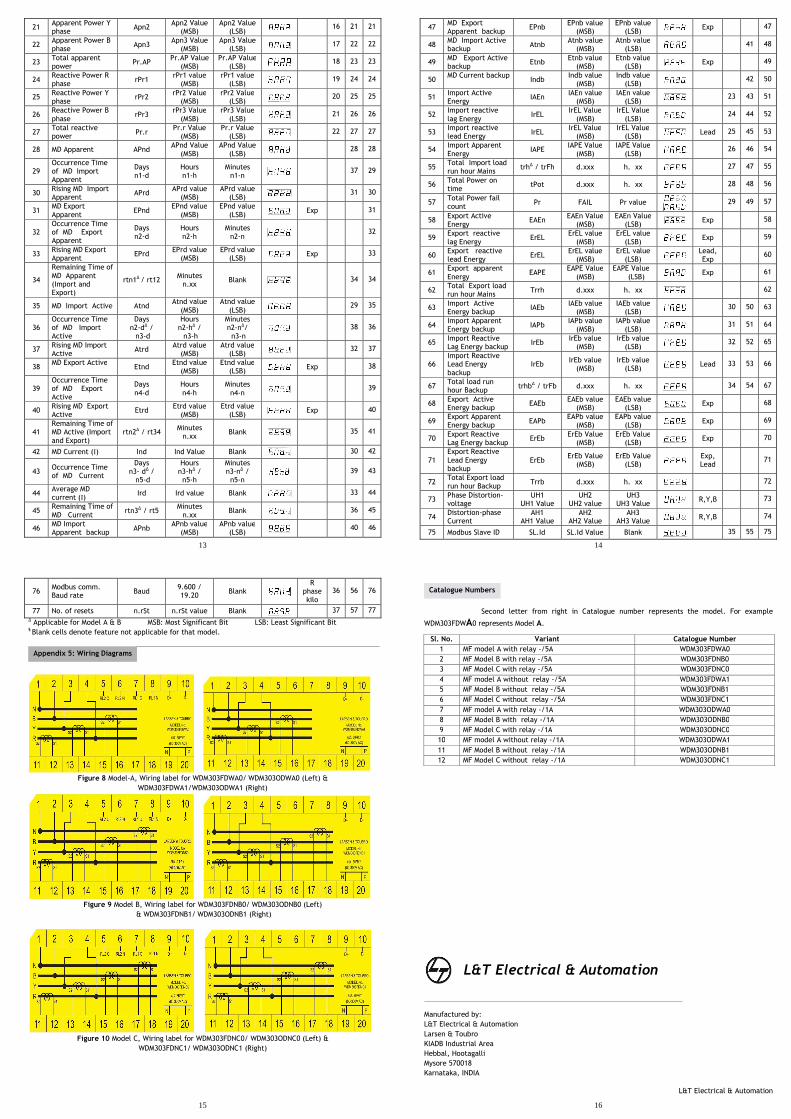
Y Applicable for Model A & B MSB: Most Significant Bit LSB: Least Significant Bit § Blank cells denote feature not applicable for that model.
Figure 8 Model-A, Wiring label for WDM303FDWA0/ WDM303ODWA0 (Left) &
WDM303FDWA1/WDM303ODWA1 (Right)
Figure 9 Model B, Wiring label for WDM303FDNB0/ WDM303ODNB0 (Left)
& WDM303FDNB1/ WDM303ODNB1 (Right)
Figure 10 Model C, Wiring label for WDM303FDNC0/ WDM303ODNC0 (Left) &
WDM303FDNC1/ WDM303ODNC1 (Right)
76 Modbus comm. Baud rate
Baud 9.600 / 19.20
Blank
R phase kilo
36 56 76
77 No. of resets n.rSt n.rSt value Blank 37 57 77
Appendix 5: Wiring Diagrams
16
Second letter from right in Catalogue number represents the model. For example
WDM303FDWA0 represents Model A.
Manufactured by:
L&T Electrical & Automation
Larsen & Toubro
KIADB Industrial Area
Hebbal, Hootagalli
Mysore 570018
Karnataka, INDIA
L&T Electrical & Automation
Sl. No. Variant Catalogue Number
1 MF model A with relay -/5A WDM303FDWA0
2 MF Model B with relay -/5A WDM303FDNB0
3 MF Model C with relay -/5A WDM303FDNC0
4 MF model A without relay -/5A WDM303FDWA1
5 MF Model B without relay -/5A WDM303FDNB1
6 MF Model C without relay -/5A WDM303FDNC1
7 MF model A with relay -/1A WDM303ODWA0
8 MF Model B with relay -/1A WDM303ODNB0
9 MF Model C with relay -/1A WDM303ODNC0
10 MF model A without relay -/1A WDM303ODWA1
11 MF Model B without relay -/1A WDM303ODNB1
12 MF Model C without relay -/1A WDM303ODNC1
L&T Electrical & Automation
Catalogue Numbers