Embed Size (px)
Citation preview
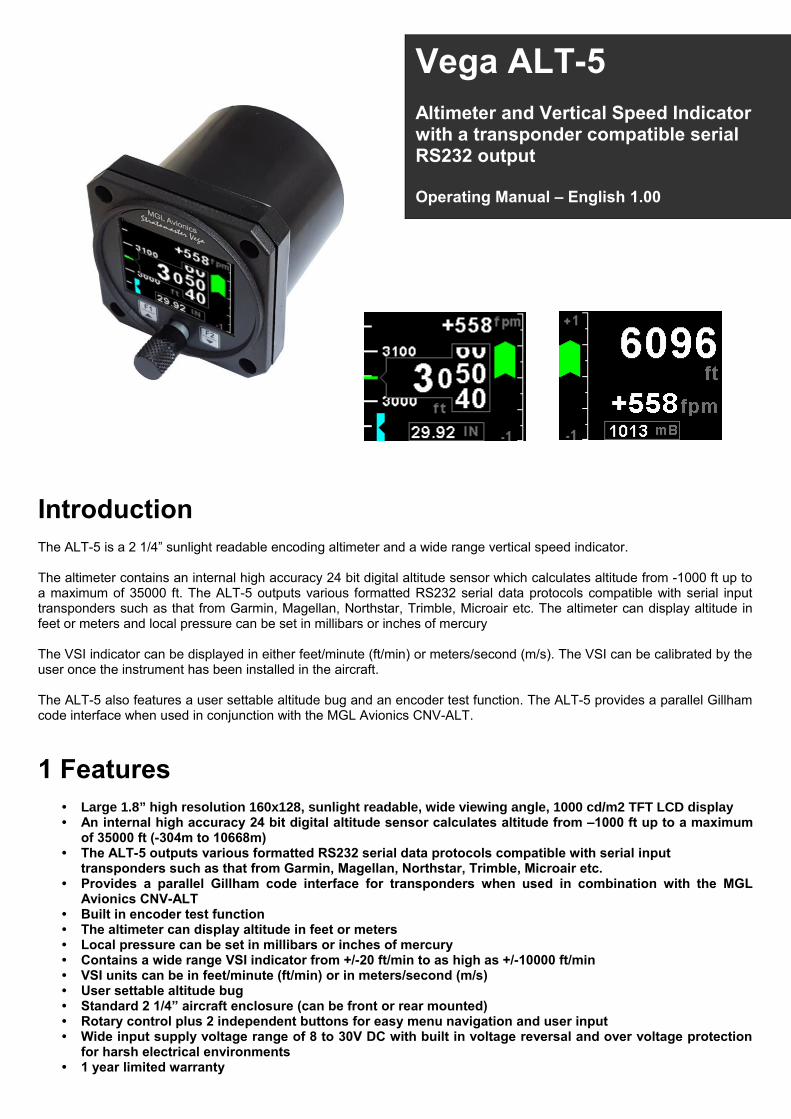
IntroductionThe ALT-5 is a 2 1/4” sunlight readable encoding altimeter and a wide range vertical speed indicator.
The altimeter contains an internal high accuracy 24 bit digital altitude sensor which calculates altitude from -1000 ft up toa maximum of 35000 ft. The ALT-5 outputs various formatted RS232 serial data protocols compatible with serial inputtransponders such as that from Garmin, Magellan, Northstar, Trimble, Microair etc. The altimeter can display altitude infeet or meters and local pressure can be set in millibars or inches of mercury
The VSI indicator can be displayed in either feet/minute (ft/min) or meters/second (m/s). The VSI can be calibrated by theuser once the instrument has been installed in the aircraft.
The ALT-5 also features a user settable altitude bug and an encoder test function. The ALT-5 provides a parallel Gillhamcode interface when used in conjunction with the MGL Avionics CNV-ALT.
1 Features• Large 1.8” high resolution 160x128, sunlight readable, wide viewing angle, 1000 cd/m2 TFT LCD display• An internal high accuracy 24 bit digital altitude sensor calculates altitude from –1000 ft up to a maximum
of 35000 ft (-304m to 10668m)• The ALT-5 outputs various formatted RS232 serial data protocols compatible with serial input
transponders such as that from Garmin, Magellan, Northstar, Trimble, Microair etc.• Provides a parallel Gillham code interface for transponders when used in combination with the MGL
Avionics CNV-ALT• Built in encoder test function• The altimeter can display altitude in feet or meters• Local pressure can be set in millibars or inches of mercury• Contains a wide range VSI indicator from +/-20 ft/min to as high as +/-10000 ft/min • VSI units can be in feet/minute (ft/min) or in meters/second (m/s)• User settable altitude bug• Standard 2 1/4” aircraft enclosure (can be front or rear mounted)• Rotary control plus 2 independent buttons for easy menu navigation and user input• Wide input supply voltage range of 8 to 30V DC with built in voltage reversal and over voltage protection
for harsh electrical environments• 1 year limited warranty
Vega ALT-5Altimeter and Vertical Speed Indicator with a transponder compatible serial RS232 output
Operating Manual – English 1.00
Vega ALT-5 Operating Manual Page 2
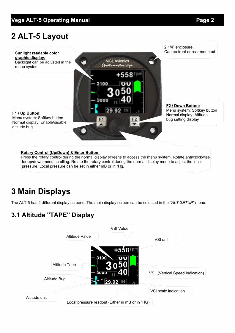
2 ALT-5 Layout
3 Main DisplaysThe ALT-5 has 2 different display screens. The main display screen can be selected in the “ALT SETUP” menu.
3.1 Altitude "TAPE" Display
F2 / Down Button:Menu system: Softkey buttonNormal display: Altitudebug setting display
Sunlight readable color graphic display:Backlight can be adjusted in the menu system
Rotary Control (Up/Down) & Enter Button:Press the rotary control during the normal display screens to access the menu system. Rotate anti/clockwise for up/down menu scrolling. Rotate the rotary control during the normal display mode to adjust the local pressure. Local pressure can be set in either mB or in “Hg.
F1 / Up Button:Menu system: Softkey buttonNormal display: Enable/disablealtitude bug
2 1/4” enclosure.Can be front or rear mounted
VSI scale indication
VS I (Vertical Speed Indication)
VSI unit
Altitude Tape
Altitude Value
Altitude Bug
Local pressure readout (Either in mB or in “HG)
VSI Value
Altitude unit

Vega ALT-5 Operating Manual Page 3
3.2 Altitude "CLASSIC" Display
3.3 Altitude Bug
Press the F2/Down button during the altitude “TAPE” display to access the altitude bug setting screen. Press the F1/UPkey to set the altitude bug to the current altitude or use the rotary control to adjust the altitude bug. Press the F2/Downkey to change the increment / decrement unit to 50 or 500. Press the rotary control to exit and save.
Press the F1/Up button during the normal altitude “TAPE” display to enable or disable the altitude bug. The bug will beyellow when in the display screen and cyan when either above or below the limits of the display.
VSI Value
VSI unit
Altitude unit
Altitude Value
VSI scale indication
VSI (Vertical Speed Indication)
Local pressure readout (Either in mB or in “HG)

Vega ALT-5 Operating Manual Page 4
4 Menu SystemPress the rotary control button during the normal display mode to enter the menu system. Use the rotary control tonavigate through the menu system.
4.1 Exiting the menu systemPress the F1/Up button to exit the menu system when the “EXIT” soft key is shown. All changes made during navigationof the menu system will be saved in non-volatile memory upon exiting. The instrument will not save any changes if youremove power before exiting the menu system.
4.2 ALT Setup (Altitude Setup)
Style:Select the altitude display screen. Options include “TAPE” or “CLASSIC”.
Altitude Unit:Select if you want the altitude displayed in ft (feet) or m (meters).
Pressure Unit:Select if you want the local pressure displayed in mB (millibars) or “Hg (inches of mercury).
Resolution:Select the resolution of the altitude value, a selection of 1,10,25 or 100 ft or m can be selected.

Vega ALT-5 Operating Manual Page 5
Cal:On the rear of your ALT-5 instrument you will find the calibration factor that has been determined to ensure the most accurate reading of your altimeter. This is the value that should be entered here. Should you have access to an accurate reference you may use this function to calibrate your altimeter. Before you do this, ensure that your calibrated and certified reference is set to the local pressure of 1013.25mB (29.92”HG). Your altimeter has been calibrated by the factoryto an accuracy of +/- one mB or approximately +/- 30 ft (10m) at sea level.
Serial Out:Select “ON” to enable the RS232 serial altitude output. This formatted serial RS232 message can be directly interfaced tovarious RS232 serial input transponders. If a parallel Gillham output is required then a CNV-ALT can be purchased from your MGL Avionics distributor to convert the RS232 output to a parallel Gillham output.
Prot:Select the protocol of the serial RS232 output message. The protocol can be selected between GARMIN AT, Magellan, Northstar / Garmin, Trimble / Garmin, MGL Avionics and Microair UAV. Please note that the baud rate is automatically adjusted according to which protocol is selected. The output format is as follows. The message contains the current pressure altitude with a fixed reference to 1013.25mB (29.92 inches mercury). All protocols use 8 databits, no parity, and 1 stop bit. The message is outputted once a second.
Protocol BaudRate
Message format Example
Garmin AT 1200 #AL, space, +/-, five altitude digits right justified zero padded, T+25, checksum, carriage return
The checksum is a simple modulo 256 sumof the binary values of the individual characters. The checksum is sent as two characters in hexadecimal format
#AL +02372T+25DF[CR]
Magellan 1200 #MGL, +/-, five altitude digits right justified zero padded, T+25, checksum, carriage return
The checksum is a simple modulo 256 sumof the binary values of the individual characters. The checksum is sent as two characters in hexadecimal format
$MGL+02372T+2513[CR]
Northstar, Garmin
4800 ALT, space, five altitude digits right justifiedzero padded, carriage return
ALT 02372[CR]
Trimble, Garmin
9600 ALT, space, five altitude digits right justifiedzero padded, carriage return
ALT 02372[CR]
MGL Avionics 9600 ALT, +/-, five altitude digits right justified zero padded ,1013.25mB (29.92”Hg) referenced, C, +/-, five altitude digits right justified zero padded (corrected to local pressure), L, local pressure setting in millibars,+/-, four digit VSI reading right justified zero padded in ft/min, X, checksum, carriage return
The checksum is a simple modulo 256 sumof the binary values of the individual characters. The checksum is sent as two characters in hexadecimal format
ALT+02372C+02372L1013+0000XCA[CR]
Microair UAV 9600 STX,a,=, five altitude digits right justified zero padded, ETX
[STX]a=02372[ETX]
STX=0x02ETX=0x03CR=0x0D
Vega ALT-5 Operating Manual Page 6
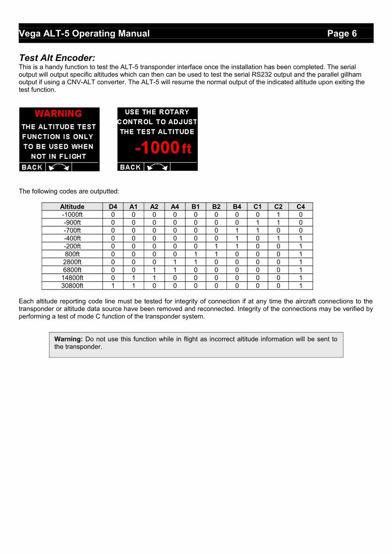
Test Alt Encoder:This is a handy function to test the ALT-5 transponder interface once the installation has been completed. The serial output will output specific altitudes which can then can be used to test the serial RS232 output and the parallel gillham output if using a CNV-ALT converter. The ALT-5 will resume the normal output of the indicated altitude upon exiting the test function.
The following codes are outputted:
Altitude D4 A1 A2 A4 B1 B2 B4 C1 C2 C4-1000ft 0 0 0 0 0 0 0 0 1 0-900ft 0 0 0 0 0 0 0 1 1 0-700ft 0 0 0 0 0 0 1 1 0 0-400ft 0 0 0 0 0 0 1 0 1 1-200ft 0 0 0 0 0 1 1 0 0 1800ft 0 0 0 0 1 1 0 0 0 1
2800ft 0 0 0 1 1 0 0 0 0 16800ft 0 0 1 1 0 0 0 0 0 1
14800ft 0 1 1 0 0 0 0 0 0 130800ft 1 1 0 0 0 0 0 0 0 1
Each altitude reporting code line must be tested for integrity of connection if at any time the aircraft connections to thetransponder or altitude data source have been removed and reconnected. Integrity of the connections may be verified byperforming a test of mode C function of the transponder system.
Warning: Do not use this function while in flight as incorrect altitude information will be sent tothe transponder.
Vega ALT-5 Operating Manual Page 7
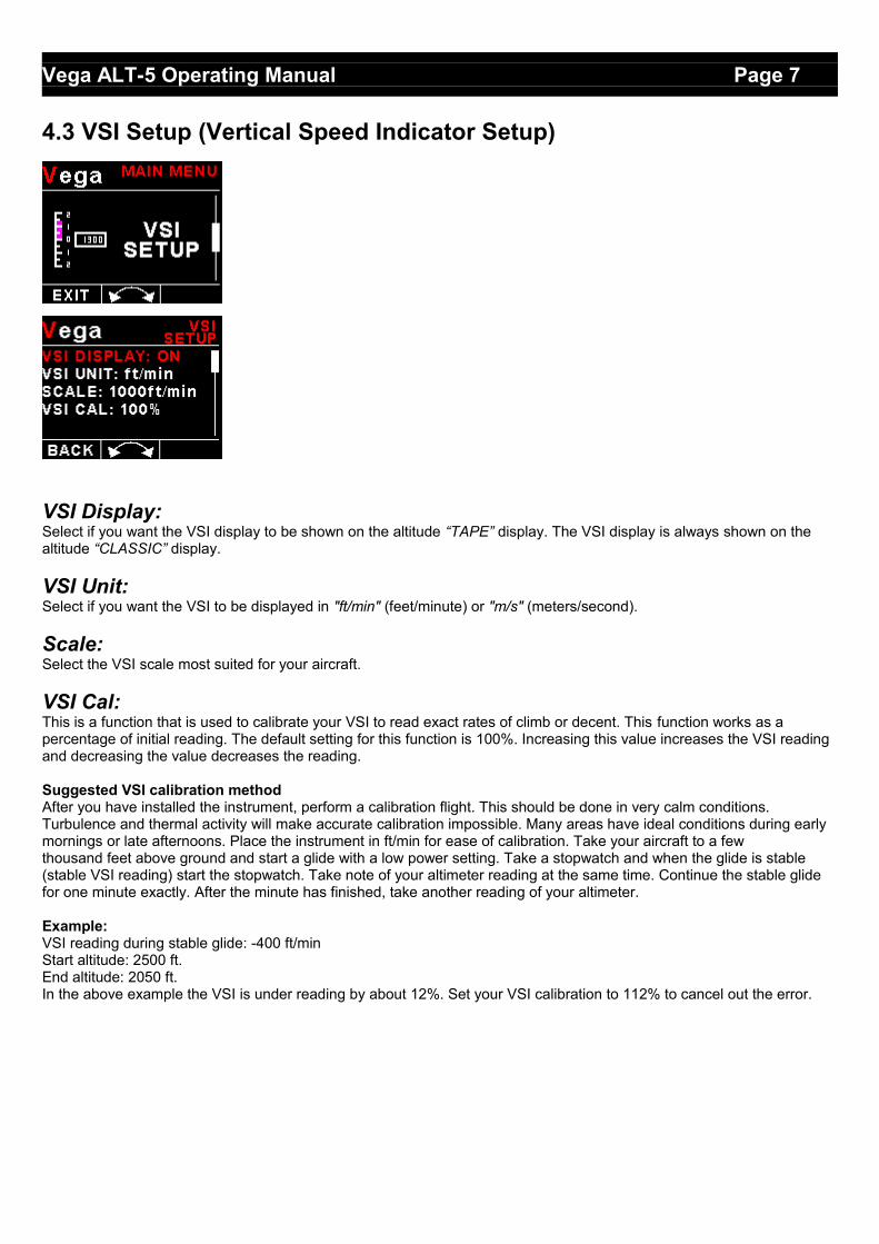
4.3 VSI Setup (Vertical Speed Indicator Setup)
VSI Display:Select if you want the VSI display to be shown on the altitude “TAPE” display. The VSI display is always shown on the altitude “CLASSIC” display.
VSI Unit:Select if you want the VSI to be displayed in "ft/min" (feet/minute) or "m/s" (meters/second).
Scale:Select the VSI scale most suited for your aircraft.
VSI Cal:This is a function that is used to calibrate your VSI to read exact rates of climb or decent. This function works as a percentage of initial reading. The default setting for this function is 100%. Increasing this value increases the VSI reading and decreasing the value decreases the reading.
Suggested VSI calibration methodAfter you have installed the instrument, perform a calibration flight. This should be done in very calm conditions.Turbulence and thermal activity will make accurate calibration impossible. Many areas have ideal conditions during earlymornings or late afternoons. Place the instrument in ft/min for ease of calibration. Take your aircraft to a fewthousand feet above ground and start a glide with a low power setting. Take a stopwatch and when the glide is stable(stable VSI reading) start the stopwatch. Take note of your altimeter reading at the same time. Continue the stable glidefor one minute exactly. After the minute has finished, take another reading of your altimeter.
Example:VSI reading during stable glide: -400 ft/minStart altitude: 2500 ft.End altitude: 2050 ft.In the above example the VSI is under reading by about 12%. Set your VSI calibration to 112% to cancel out the error.
Vega ALT-5 Operating Manual Page 8
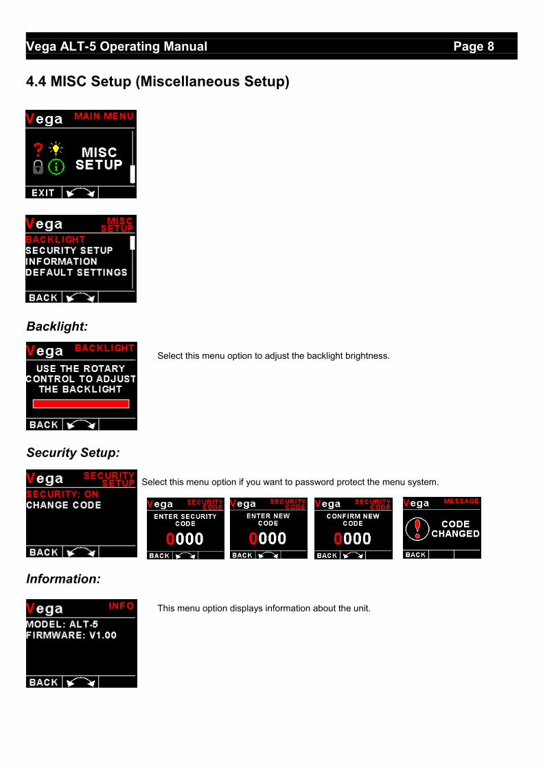
4.4 MISC Setup (Miscellaneous Setup)
Backlight:
Select this menu option to adjust the backlight brightness.
Security Setup:
Select this menu option if you want to password protect the menu system.
Information:
This menu option displays information about the unit.

Vega ALT-5 Operating Manual Page 9
Default Settings:
Select this menu option to reset all the settings to factory defaults.
5 Loading factory default settings
Press and hold the F1/Up button and rotary control during power up to load the pre-programmed factory default settings. The following screen will be displayed:
Factory default settings can also be loaded in the Miscellaneous setup menu.
6 Error Messages
Unit settings CRC error. Load default settings to restore to factory defaults. If the error message still persists then it could possibly be a non-volatile memory failure in which case the instrument will then have to be returned to the factory.
Calibration constants CRC error. The instrument could possibly have a non-volatile memory failure in which case the instrument will then have to be returned to the factory.
Altitude sensor error. The instrument could have a faulty altitude sensor in which case the instrument will then have to be returned to the factory.

Vega ALT-5 Operating Manual Page 10
7 ALT-5 SpecificationsOperating Temperature Range -10ºC to 60ºC (14ºF to 140ºF)Storage Temperature Range -20ºC to 80ºC (-4ºF to 176ºF)Humidity <85% non-condensing
Power Supply8 to 30Vdc SMPS (switch mode power supply) with built in 33V over voltage and reverse voltage protection
Current ConsumptionApprox. 73mA @ 13.8V (backlight highest setting), 33mA @13.8V (backlight lowest setting)
Display
1.8” 160x128 pixel active matrix TFT display.1000 cd/m2Sunlight readable with anti-glare coatingLED Backlight is user configurable
Alarm OutputOpen collector transistor switch to groundMaximum rating 0.5A
Altitude sensor ADC resolution 24 bitDimensions see Vega series dimensional drawingEnclosure 2 1/4” ABS, black in color, front or rear mounting. Flame retardant.Weight Approx. 120 grams (Instrument excluding cables)Non-volatile memory storage 100000 write cyclesAltimeter range -1000ft to 35 000ft (-304m to 10668m)Altitude units ft or mPressure units InHG or mBVSI range +-20ft/min to +-10000ft/minVSI units ft/min or m/sSerial Port RS232 voltage levels
8 Operating the alarmsThe alarm output can be used to switch an external alarm indicator. The external alarm switch is an open collectortransistor switch to ground with a maximum rating of 0.5A DC. It is possible to wire the alarm contacts of severalStratomaster instruments in parallel should this be desired. To avoid false activation of the alarms, the alarm function isonly active 10 seconds after the instrument has powered up.
9 Firmware Upgrading
The ALT-5 can be upgraded in the field by connecting the RS232 port to a PC and running the firmware update program.Note that only the RS232 port can be used to upgrade the firmware.
Please see the Vega firmware upgrading document for more information.
Vega ALT-5 Operating Manual Page 11
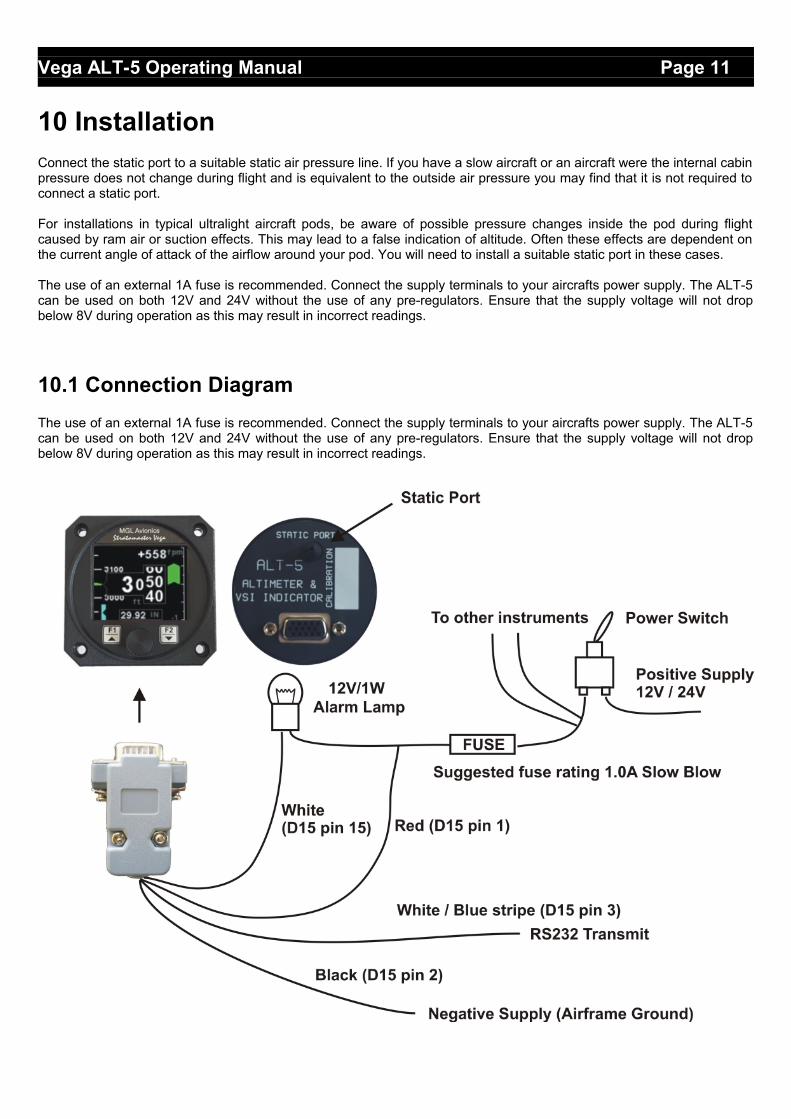
10 InstallationConnect the static port to a suitable static air pressure line. If you have a slow aircraft or an aircraft were the internal cabinpressure does not change during flight and is equivalent to the outside air pressure you may find that it is not required toconnect a static port.
For installations in typical ultralight aircraft pods, be aware of possible pressure changes inside the pod during flightcaused by ram air or suction effects. This may lead to a false indication of altitude. Often these effects are dependent onthe current angle of attack of the airflow around your pod. You will need to install a suitable static port in these cases.
The use of an external 1A fuse is recommended. Connect the supply terminals to your aircrafts power supply. The ALT-5can be used on both 12V and 24V without the use of any pre-regulators. Ensure that the supply voltage will not dropbelow 8V during operation as this may result in incorrect readings.
10.1 Connection Diagram
The use of an external 1A fuse is recommended. Connect the supply terminals to your aircrafts power supply. The ALT-5can be used on both 12V and 24V without the use of any pre-regulators. Ensure that the supply voltage will not dropbelow 8V during operation as this may result in incorrect readings.

Vega ALT-5 Operating Manual Page 12
10.2 ALT-5 Cable connections
Main connector (D15 connector: Unit Female, Cable Male)
11 CleaningThe unit should not be cleaned with any abrasive substances. The screen is very sensitive to certain cleaning materialsand should only be cleaned using a clean, damp cloth.
12 WarrantyThis product carries a warranty for a period of one year from date of purchase against faulty workmanship or defectivematerials, provided there is no evidence that the unit has been mishandled or misused. Warranty is limited to thereplacement of faulty components and includes the cost of labor. Shipping costs are for the account of the purchaser.
Damage as a result of applying excessive pressure to the static pressure port are excluded from warranty.
D15 Pin Color Function1 Red 8-30Vdc power via power switch / circuit
breaker and fuse.2 Black Ground. 3 White/Blue
StripeRS232 Transmit data (Firmware upgrading / RS232 Altitude output)
4 - RS232 Receive data (Firmware upgrading)15 White Alarm Output (Open collector)
Note: Product warranty excludes damages caused by unprotected, unsuitable or incorrectly wiredelectrical supplies and or sensors, and damage caused by inductive loads.
Warning: The ALT-5 is not waterproof, serious damage could occur if the unit is exposed towater and/or spray jets.

Vega ALT-5 Operating Manual Page 13
13 DisclaimerOperation of this instrument is the sole responsibility of the purchaser of the unit. The user must make themselves familiarwith the operation of this instrument and the effect of any possible failure or malfunction.
This instrument is not certified by the FAA. Fitting of this instrument to certified aircraft is subject to the rules andconditions pertaining to such in your country. Please check with your local aviation authorities if in doubt. This instrumentis intended for ultralight, microlight, homebuilt and experimental aircraft. Operation of this instrument is the soleresponsibility of the pilot in command (PIC) of the aircraft. This person must be proficient and carry a valid and relevantpilot’s license. This person has to make themselves familiar with the operation of this instrument and the effect of anypossible failure or malfunction. Under no circumstances does the manufacturer condone usage of this instrument for IFRflights.
IMPORTANT NOTICE:You must make your own determination if the products sold by MGL Avionics are safe and effective for your intended applications. MGL Avionics makes no representations or warranties as to either the suitability of any of the products we sell as to your particular application or the compatibility of any of the products we sell with other products you may buy from us or anywhere else, and we disclaim any warranties or representations that may otherwise arise by law. Also, we offer no specific advice on how to install any of the products we sell other than passing along anything that may have been provided to us by the manufacturer or other issues. If you are in need of further information or guidance, please turn to the manufacturer, FAA Advisory Circulars and guidance materials, the Experimental Aircraft Association, or other reputable sources.
Other instruments in the Stratomaster Vega series
AHRS-1 Artificial Horizon and Magnetic Compass IndicatorALT-5 Altimeter and Vertical Speed Indicator (VSI)ASI-4 Airspeed Indicator (ASI)ASV-1 Altimeter, Airspeed (ASI) and Vertical Speed Indicator (VSI)EMS-1 Engine Monitoring SystemFF-4 Fuel ComputerINFO-1 Information Display (G-force meter, RTC, Outside Air Temperature (OAT), Volts and
Current display)MAG-1 Magnetic Compass IndicatorMAP-3 Manifold Pressure and RPM IndicatorRPM-1 Universal Engine / Rotor RPM IndicatorTC-4 4-Channel Thermocouple (EGT/CHT) IndicatorTP-3 Universal Temperature and Pressure Indicator
The manufacturer reserves the right to alter any specification without notice.