Embed Size (px)
Citation preview
VE-WCN, VE-WCC, VE-WCSMI, VE-WCSO
Wireless Controller for Venture TTL 600 Ws MonolightINSTRUCTIONS
Table of Contents
Introduction ......................................................................3Overview ...................................................................... 4-8Precautions .................................................................9-10Installing the Batteries ...................................................11Mounting the Controller .................................................11Powering On...................................................................12
Restoring Factory Presets ..........................................12Power-Saving Feature ................................................12
Channel Selection ..........................................................13Setting the Master Group ...............................................14Setting the ID Number ...................................................15TTL Mode ..................................................................16-18
High-Speed Sync (HSS) .................................................19Second Curtain Sync (SCS) ............................................19Manual Mode .................................................................20Firing a Test ...................................................................21Lockout Mode ................................................................21Using the Modeling Light ..........................................22-23Cell (Slave) Mode ...........................................................24Troubleshooting ........................................................25-26Specifications ...............................................................27FCC Compliance ............................................................27Warranty ......................................................................28
3
Thank you for choosing Impact.
The Impact Venture Wireless Controller is a compact wireless 2.4 GHz transmitter that provides the Venture TTL 600 Monolight with through-the-lens (TTL) and high-speed sync (HSS) functionality. It allows the user to control and trigger the flash from a distance of up to 328′ (100 m) via 2.4 GHz wireless transmission. It also sets channels, groups, and ID numbers, and adjusts monolight and modeling lamp power output.
To use the capabilities of the Venture TTL 600’s integrated wireless receiver, the Venture Controller is compatible with most Canon, Nikon, and Sony cameras with a hot-shoe mount. It can also be connected to a camera with a PC port via a PC sync cable.
Introduction
4
Overview
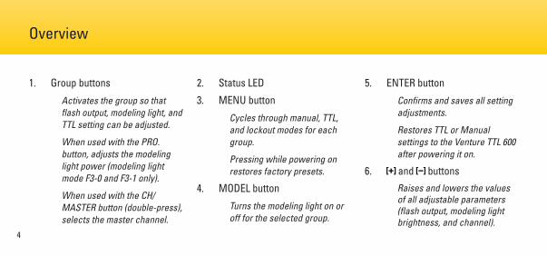
1. Group buttons
Activates the group so that flash output, modeling light, and TTL setting can be adjusted.
When used with the PRO. button, adjusts the modeling light power (modeling light mode F3-0 and F3-1 only).
When used with the CH/MASTER button (double-press), selects the master channel.
2. Status LED
3. MENU button
Cycles through manual, TTL, and lockout modes for each group.
Pressing while powering on restores factory presets.
4. MODEL button
Turns the modeling light on or off for the selected group.
5. ENTER button
Confirms and saves all setting adjustments.
Restores TTL or Manual settings to the Venture TTL 600 after powering it on.
6. and buttonsRaises and lowers the values of all adjustable parameters (flash output, modeling light brightness, and channel).
5
1
3
5
4 7
8
2
Overview (continued)
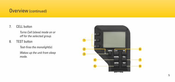
7. CELL button
Turns Cell (slave) mode on or off for the selected group.
8. TEST button
Test-fires the monolight(s).
Wakes up the unit from sleep mode.
6
6
Overview (continued)
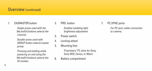
1. CH/MASTER button
Single-press used with the and buttons selects the
channel.
Double-press used with GROUP button selects master group.
Pressing and holding while powering on and using the
and buttons selects the ID number.
2. PRO. button
Enables modeling light brightness adjustment.
3. Power switch
4. Locking wheel
5. Mounting foot
Proprietary TTL shoe for Sony, Sony MIS, Canon, or Nikon.
6. Battery compartment
7. PC.SYNC ports
For PC sync cable connection to camera.
7
Overview (continued)
1
5
6
4
3
2
7
8
CH ENERGY MODEL
CELL
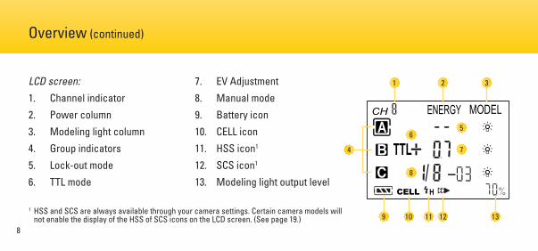
LCD screen:
1. Channel indicator
2. Power column
3. Modeling light column
4. Group indicators
5. Lock-out mode
6. TTL mode
7. EV Adjustment
8. Manual mode
9. Battery icon
10. CELL icon
11. HSS icon1
12. SCS icon1
13. Modeling light output level
4
31
109 11 12 13
2
56
Overview (continued)
8
7
1 HSS and SCS are always available through your camera settings. Certain camera models will not enable the display of the HSS of SCS icons on the LCD screen. (See page 19.)
9
Precautions ⚠⚡
• The Venture Wireless TTL Controller’s 2.4 GHz radio signal can be affected by electrical current, magnetic fields, radio signals, wireless routers, mobile phones, and other electronic devices. Buildings, walls, trees, fences, or cars can also impede the controller’s performance. If your Venture Wireless TTL Controller will not communicate
with your flash, move it to a slightly different location that is free of obstructions or interference.
• There are no user-serviceable parts inside the devices. Do not attempt to disassemble or perform any unauthorized modification.
• Do not operate the Venture Wireless Controller in the presence of flammable gas or vapors.
• Do not handle with wet hands or immerse in or expose to water or rain. Failure to observe this precaution could result in fire or electric shock.
10
Precautions ⚠⚡ (continued)
• Keep out of the reach of children.
• Observe caution when handling batteries. Batteries may leak or explode if improperly handled. Use only the batteries listed in this manual. Make certain to align batteries with the correct polarity.
• Batteries are prone to leakage when fully discharged. To avoid damage to the product, be sure to remove the batteries before leaving the product unattended for prolonged periods or when no charge remains.
• Do not use or leave the devices in conditions of extreme heat, severe cold, or high humidity.
• Turn off the camera and/or flash’s power before inserting or removing any cord.
• Dispose of used batteries, packaging, and old devices in accordance with appropriate local environmental regulations.
• All images are for illustrative purposes only.
11
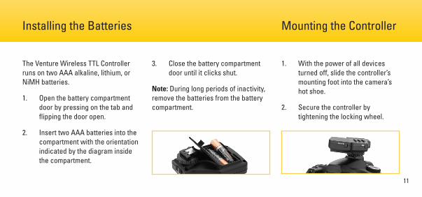
The Venture Wireless TTL Controller runs on two AAA alkaline, lithium, or NiMH batteries.
1. Open the battery compartment door by pressing on the tab and flipping the door open.
2. Insert two AAA batteries into the compartment with the orientation indicated by the diagram inside the compartment.
3. Close the battery compartment door until it clicks shut.
Note: During long periods of inactivity, remove the batteries from the battery compartment.
1. With the power of all devices turned off, slide the controller’s mounting foot into the camera’s hot shoe.
2. Secure the controller by tightening the locking wheel.
Installing the Batteries Mounting the Controller
12
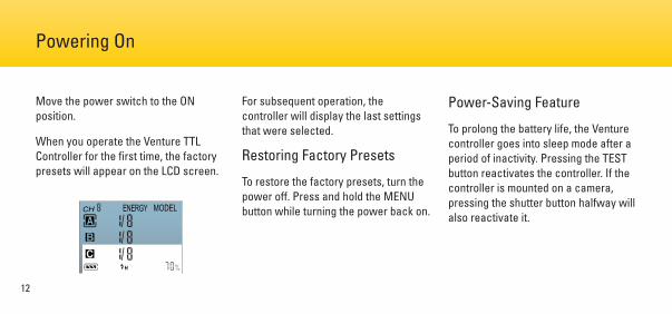
Move the power switch to the ON position.
When you operate the Venture TTL Controller for the first time, the factory presets will appear on the LCD screen.
For subsequent operation, the controller will display the last settings that were selected.
Restoring Factory Presets
To restore the factory presets, turn the power off. Press and hold the MENU button while turning the power back on.
Power-Saving Feature
To prolong the battery life, the Venture controller goes into sleep mode after a period of inactivity. Pressing the TEST button reactivates the controller. If the controller is mounted on a camera, pressing the shutter button halfway will also reactivate it.
Powering On
CH ENERGY MODEL
13
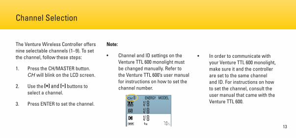
The Venture Wireless Controller offers nine selectable channels (1–9). To set the channel, follow these steps:
1. Press the CH/MASTER button. CH will blink on the LCD screen.
2. Use the and buttons to select a channel.
3. Press ENTER to set the channel.
Note:
• Channel and ID settings on the Venture TTL 600 monolight must be changed manually. Refer to the Venture TTL 600’s user manual for instructions on how to set the channel number.
• In order to communicate with your Venture TTL 600 monolight, make sure it and the controller are set to the same channel and ID. For instructions on how to set the channel, consult the user manual that came with the Venture TTL 600.
Channel Selection
CH ENERGY MODEL
14
Any of the three groups can be set as the master group. To set the master group, follow these steps:
1. Press the CH/MASTER button twice. The icon of the selected master group will blink.
2. While the master group icon is blinking, press the group button you want to designate as the master. The new master group icon will now blink.
3. Press ENTER to set the master group. The new master group icon will be highlighted.
Note: Group settings on the Venture TTL 600 monolight must be changed manually. Refer to the Venture TTL 600’s user manual for instructions on how to change the group.
Setting the Master Group
15
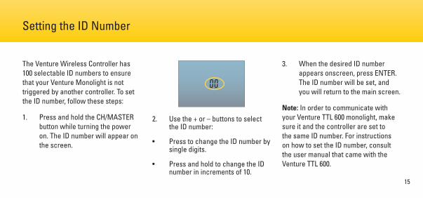
The Venture Wireless Controller has 100 selectable ID numbers to ensure that your Venture Monolight is not triggered by another controller. To set the ID number, follow these steps:
1. Press and hold the CH/MASTER button while turning the power on. The ID number will appear on the screen.
2. Use the + or – buttons to select the ID number:
• Press to change the ID number by single digits.
• Press and hold to change the ID number in increments of 10.
3. When the desired ID number appears onscreen, press ENTER. The ID number will be set, and you will return to the main screen.
Note: In order to communicate with your Venture TTL 600 monolight, make sure it and the controller are set to the same ID number. For instructions on how to set the ID number, consult the user manual that came with the Venture TTL 600.
Setting the ID Number
16
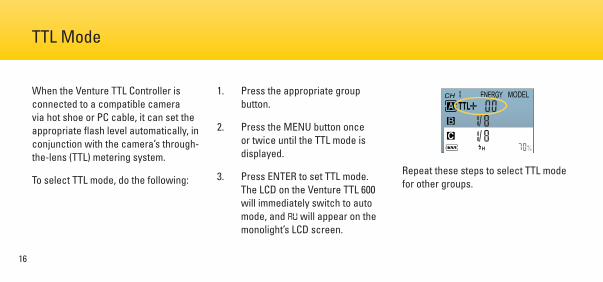
When the Venture TTL Controller is connected to a compatible camera via hot shoe or PC cable, it can set the appropriate flash level automatically, in conjunction with the camera’s through-the-lens (TTL) metering system.
To select TTL mode, do the following:
1. Press the appropriate group button.
2. Press the MENU button once or twice until the TTL mode is displayed.
3. Press ENTER to set TTL mode. The LCD on the Venture TTL 600 will immediately switch to auto mode, and AU will appear on the monolight’s LCD screen.
Repeat these steps to select TTL mode for other groups.
TTL Mode
CH ENERGY MODEL
17
Important!
To take advantage of the Venture TTL Controller’s functions, make sure your Venture TTL 600 monolight(s) are set to the proper channel, group, and ID number. Refer to the Venture TTL 600’s user manual for information on setting these parameters.
Notes:
• The Venture TTL 600 will remain in auto (AU) mode when the controller is turned off. In order to switch the monolight back to manual mode, turn it off and then turn it back on.
• If the Venture controller is in TTL mode when powered on, but the Venture monolight is in manual mode, press ENTER to switch the monolight to TTL (AU) mode. Previous TTL settings will have been saved.
TTL Mode (continued)
18
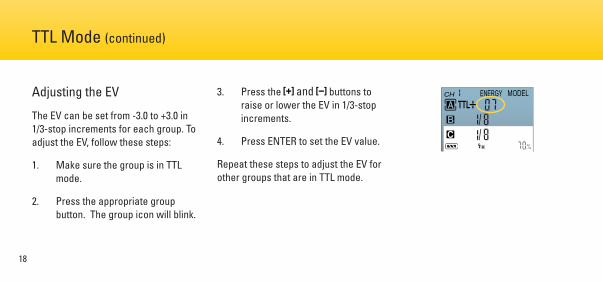
Adjusting the EV
The EV can be set from -3.0 to +3.0 in 1/3-stop increments for each group. To adjust the EV, follow these steps:
1. Make sure the group is in TTL mode.
2. Press the appropriate group button. The group icon will blink.
3. Press the and buttons to raise or lower the EV in 1/3-stop increments.
4. Press ENTER to set the EV value.
Repeat these steps to adjust the EV for other groups that are in TTL mode.
TTL Mode (continued)
CH ENERGY MODEL
19
High-speed sync lets you use shutter speeds as fast as 1/8000 second. HSS is always available with the Venture Wireless Controller. See your camera’s manual to check for your camera’s fastest shutter speed and setting for HSS.
Tip: Use F4-2 (power mode) on the Venture TTL 600 Monolight to maximize flash output with HSS. See the Venture TTL 600 monolight’s instructions for details.
For Nikon and Sony cameras, refer to your camera’s manual to activate SCS. The Venture wireless controller will automatically switch to SCS mode. Once SCS is disabled on your camera, the Venture controller will return to normal operating mode.
For select Canon cameras, first activate SCS mode on your camera. The Status LED on the controller will blink rapidly to indicate that the camera has been set to SCS. Press and hold the ENTER
button until the HSS icon switches to the SCS icon. The controller is now in SCS mode. To exit SCS mode, press and hold the ENTER button until the SCS icon changes back to the HSS icon.
Note: HSS and SCS are always available through your camera. Certain camera models will not enable the display of the HSS of SCS icons on the LCD screen. Even if the icons are not displayed, HSS and SCS will be active once you make the appropriate settings on your camera.
High-Speed Sync (HSS) Second Curtain Sync (SCS)
20
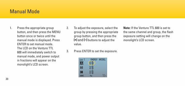
1. Press the appropriate group button, and then press the MENU button once or twice until the manual mode is displayed. Press ENTER to set manual mode. The LCD on the Venture TTL 600 will immediately switch to manual mode, and power output in fractions will appear on the monolight’s LCD screen.
2. To adjust the exposure, select the group by pressing the appropriate group button, and then press the
and buttons to adjust the value.
3. Press ENTER to set the exposure.
Note: If the Venture TTL 600 is set to the same channel and group, the flash exposure setting will change on the monolight’s LCD screen.
Manual Mode
CH ENERGY MODEL
21
1. Make sure the Venture TTL 600 is set to the same channel, group, and ID number as the Venture TTL Controller.
2. Set the flash power output to the desired brightness.
3. When the Venture TTL 600 is ready to fire, press the TEST button. The monolight will fire a test flash.
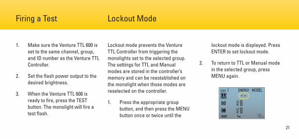
Lockout mode prevents the Venture TTL Controller from triggering the monolights set to the selected group. The settings for TTL and Manual modes are stored in the controller’s memory and can be reestablished on the monolight when those modes are reselected on the controller.
1. Press the appropriate group button, and then press the MENU button once or twice until the
lockout mode is displayed. Press ENTER to set lockout mode.
2. To return to TTL or Manual mode in the selected group, press MENU again.
Firing a Test Lockout Mode
CH ENERGY MODEL
22
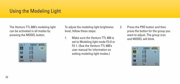
The Venture TTL 600’s modeling light can be activated in all modes by pressing the MODEL button.
To adjust the modeling light brightness level, follow these steps:
1. Make sure the Venture TTL 600 is set to Modeling light mode F3-0 or F3-1. (See the Venture TTL 600’s user manual for information on setting modeling light modes.)
2. Press the PRO button and then press the button for the group you want to adjust. The group icon and MODEL will blink.
Using the Modeling Light
CH ENERGY MODELCH ENERGY MODEL
23
Using the Modeling Light (continued)
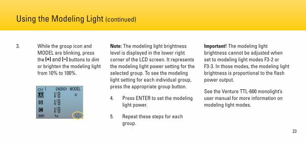
3. While the group icon and MODEL are blinking, press the and buttons to dim or brighten the modeling light from 10% to 100%.
Note: The modeling light brightness level is displayed in the lower right corner of the LCD screen. It represents the modeling light power setting for the selected group. To see the modeling light setting for each individual group, press the appropriate group button.
4. Press ENTER to set the modeling light power.
5. Repeat these steps for each group.
Important! The modeling light brightness cannot be adjusted when set to modeling light modes F3-2 or F3-3. In those modes, the modeling light brightness is proportional to the flash power output.
See the Venture TTL-600 monolight’s user manual for more information on modeling light modes.
CH ENERGY MODEL
24
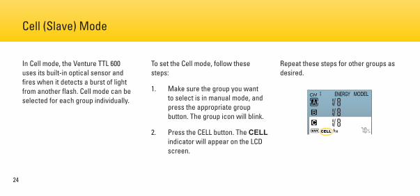
In Cell mode, the Venture TTL 600 uses its built-in optical sensor and fires when it detects a burst of light from another flash. Cell mode can be selected for each group individually.
To set the Cell mode, follow these steps:
1. Make sure the group you want to select is in manual mode, and press the appropriate group button. The group icon will blink.
2. Press the CELL button. The CELL indicator will appear on the LCD screen.
Repeat these steps for other groups as desired.
Cell (Slave) Mode
CH ENERGY MODEL
CELL
25
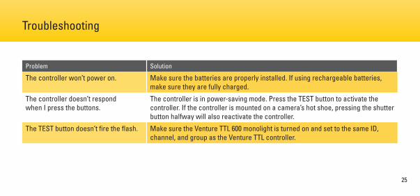
Problem Solution
The controller won’t power on. Make sure the batteries are properly installed. If using rechargeable batteries, make sure they are fully charged.
The controller doesn’t respond when I press the buttons.
The controller is in power-saving mode. Press the TEST button to activate the controller. If the controller is mounted on a camera’s hot shoe, pressing the shutter button halfway will also reactivate the controller.
The TEST button doesn’t fire the flash. Make sure the Venture TTL 600 monolight is turned on and set to the same ID, channel, and group as the Venture TTL controller.
Troubleshooting
26
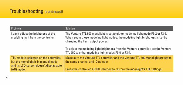
Problem Solution
I can’t adjust the brightness of the modeling light from the controller.
The Venture TTL 600 monolight is set to either modeling light mode F3-2 or F3-3. When set to these modeling light modes, the modeling light brightness is set by changing the flash output power.
To adjust the modeling light brightness from the Venture controller, set the Venture TTL 600 to either modeling light modes F3-0 or F3-1.
TTL mode is selected on the controller, but the monolight is in manual mode, and its LCD screen doesn’t display auto (AU) mode.
Make sure the Venture TTL controller and the Venture TTL 600 monolight are set to the same channel and ID number.
Press the controller's ENTER button to restore the monolight’s TTL settings.
Troubleshooting (continued)
27
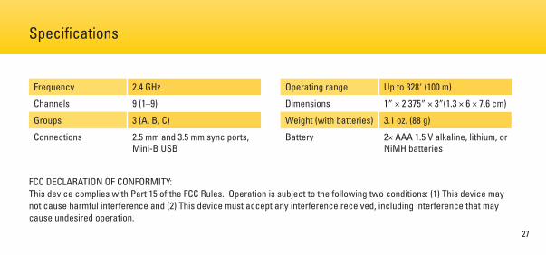
Frequency 2.4 GHz
Channels 9 (1–9)
Groups 3 (A, B, C)
Connections 2.5 mm and 3.5 mm sync ports, Mini-B USB
Operating range Up to 328′ (100 m)
Dimensions 1″ × 2.375″ × 3″(1.3 × 6 × 7.6 cm)
Weight (with batteries) 3.1 oz. (88 g)
Battery 2× AAA 1.5 V alkaline, lithium, or NiMH batteries
Specifications
FCC DECLARATION OF CONFORMITY:This device complies with Part 15 of the FCC Rules. Operation is subject to the following two conditions: (1) This device may not cause harmful interference and (2) This device must accept any interference received, including interference that may cause undesired operation.

One-Year Limited WarrantyThis Impact product is warranted to the original purchaser to be free from defects in materials and workmanship under normal consumer use for a period of one (1) year from the original purchase date or thirty (30) days after replacement, whichever occurs later. The warranty provider’s responsibility with respect to this limited warranty shall be limited solely to repair or replacement, at the provider’s discretion, of any product that fails during normal use of this product in its intended manner and in its intended environment. Inoperability of the product or part(s) shall be determined by the warranty provider. If the product has been discontinued, the warranty provider reserves the right to replace it with a model of equivalent quality and function.
This warranty does not cover damage or defect caused by misuse, neglect, accident, alteration, abuse, improper installation or maintenance. EXCEPT AS PROVIDED HEREIN, THE WARRANTY PROVIDER MAKES NEITHER ANY EXPRESS WARRANTIES NOR ANY IMPLIED WARRANTIES, INCLUDING BUT NOT LIMITED TO ANY IMPLIED WARRANTY OF MERCHANTABILITY OR FITNESS FOR A PARTICULAR PURPOSE. This warranty provides you with specific legal rights, and you may also have additional rights that vary from state to state.
To obtain warranty coverage, contact the Impact Customer Service Department to obtain a return merchandise authorization (“RMA”) number, and return the defective product to Impact along with the RMA number and proof of purchase. Shipment of the defective product is at the purchaser’s own risk and expense.
For more information or to arrange service, visit www.impactstudiolighting.com or call Customer Service at 212-594-2353.
Product warranty provided by the Gradus Group. www.gradusgroup.com
Impact is a registered trademark of the Gradus Group. © 2016 Gradus Group LLC. All Rights Reserved.GG5