Embed Size (px)
Citation preview
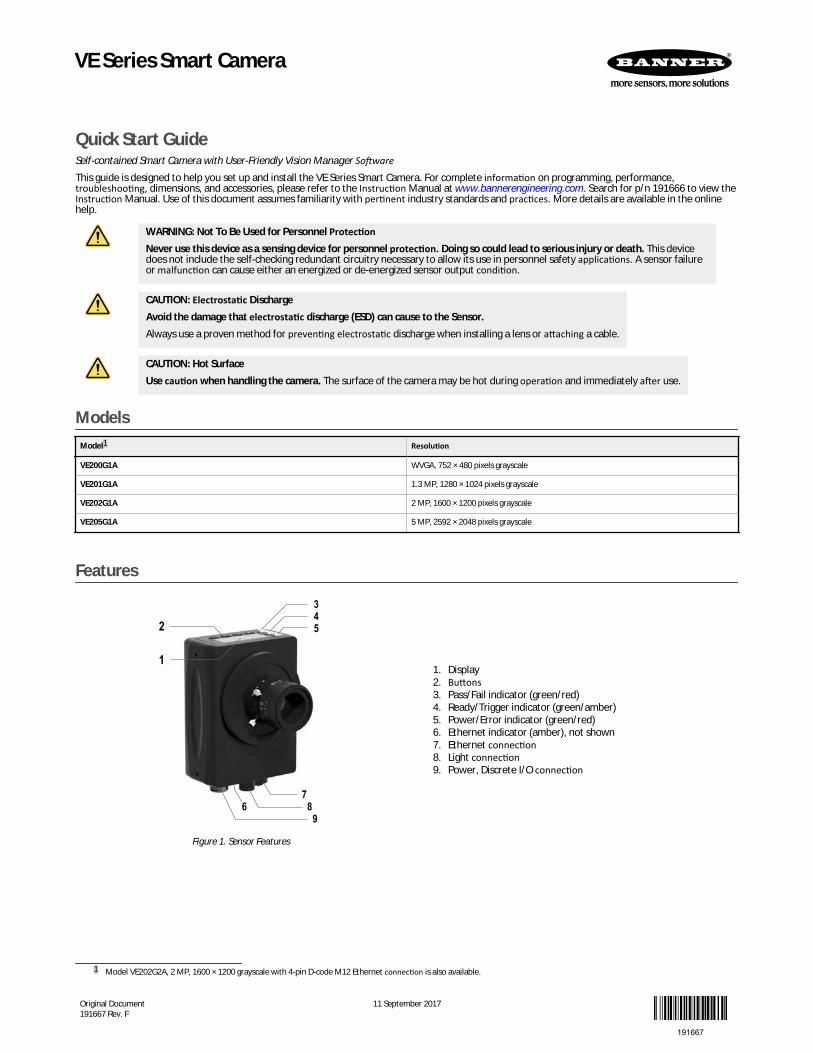
Quick Start GuideSelf-contained Smart Camera with User-Friendly Vision Manager SoftwareThis guide is designed to help you set up and install the VE Series Smart Camera. For complete information on programming, performance,troubleshooting, dimensions, and accessories, please refer to the Instruction Manual at www.bannerengineering.com. Search for p/n 191666 to view theInstruction Manual. Use of this document assumes familiarity with pertinent industry standards and practices. More details are available in the onlinehelp.
WARNING: Not To Be Used for Personnel ProtectionNever use this device as a sensing device for personnel protection. Doing so could lead to serious injury or death. This devicedoes not include the self-checking redundant circuitry necessary to allow its use in personnel safety applications. A sensor failureor malfunction can cause either an energized or de-energized sensor output condition.
CAUTION: Electrostatic DischargeAvoid the damage that electrostatic discharge (ESD) can cause to the Sensor.Always use a proven method for preventing electrostatic discharge when installing a lens or attaching a cable.
CAUTION: Hot SurfaceUse caution when handling the camera. The surface of the camera may be hot during operation and immediately after use.
ModelsModel1 Resolution
VE200G1A WVGA, 752 × 480 pixels grayscale
VE201G1A 1.3 MP, 1280 × 1024 pixels grayscale
VE202G1A 2 MP, 1600 × 1200 pixels grayscale
VE205G1A 5 MP, 2592 × 2048 pixels grayscale
Features
1
2
345
76 8
9
Figure 1. Sensor Features
1. Display2. Buttons3. Pass/Fail indicator (green/red)4. Ready/Trigger indicator (green/amber)5. Power/Error indicator (green/red)6. Ethernet indicator (amber), not shown7. Ethernet connection8. Light connection9. Power, Discrete I/O connection
1 Model VE202G2A, 2 MP, 1600 × 1200 grayscale with 4-pin D-code M12 Ethernet connection is also available.
VE Series Smart Camera
Original Document191667 Rev. F
11 September 2017
191667
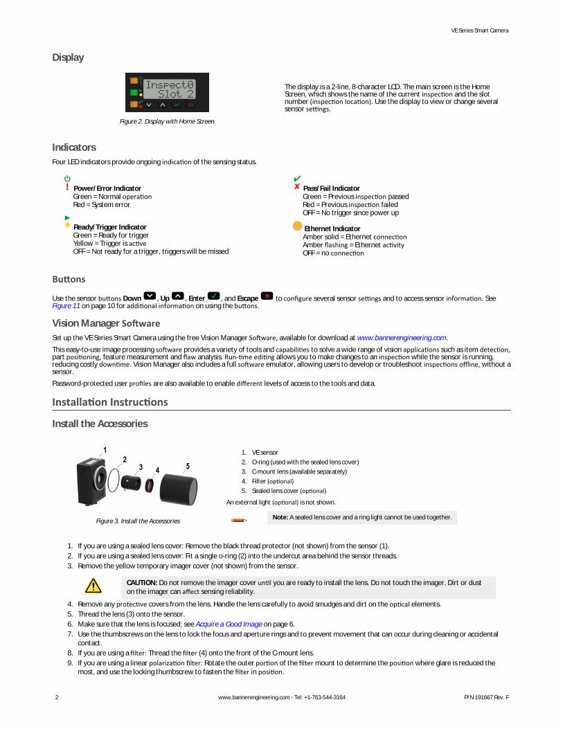
Display
Figure 2. Display with Home Screen
The display is a 2-line, 8-character LCD. The main screen is the HomeScreen, which shows the name of the current inspection and the slotnumber (inspection location). Use the display to view or change severalsensor settings.
IndicatorsFour LED indicators provide ongoing indication of the sensing status.
Power/Error IndicatorGreen = Normal operationRed = System error
Ready/Trigger IndicatorGreen = Ready for triggerYellow = Trigger is activeOFF = Not ready for a trigger, triggers will be missed
Pass/Fail IndicatorGreen = Previous inspection passedRed = Previous inspection failedOFF = No trigger since power up
Ethernet IndicatorAmber solid = Ethernet connectionAmber flashing = Ethernet activityOFF = no connection
Buttons
Use the sensor buttons Down , Up , Enter , and Escape to configure several sensor settings and to access sensor information. See Figure 11 on page 10 for additional information on using the buttons.
Vision Manager SoftwareSet up the VE Series Smart Camera using the free Vision Manager Software, available for download at www.bannerengineering.com.This easy-to-use image processing software provides a variety of tools and capabilities to solve a wide range of vision applications such as item detection,part positioning, feature measurement and flaw analysis. Run-time editing allows you to make changes to an inspection while the sensor is running,reducing costly downtime. Vision Manager also includes a full software emulator, allowing users to develop or troubleshoot inspections offline, without asensor.Password-protected user profiles are also available to enable different levels of access to the tools and data.
Installation Instructions
Install the Accessories
12
3 54
Figure 3. Install the Accessories
1. VE sensor2. O-ring (used with the sealed lens cover)3. C-mount lens (available separately)4. Filter (optional)5. Sealed lens cover (optional)
An external light (optional) is not shown.
Note: A sealed lens cover and a ring light cannot be used together.
1. If you are using a sealed lens cover: Remove the black thread protector (not shown) from the sensor (1).2. If you are using a sealed lens cover: Fit a single o-ring (2) into the undercut area behind the sensor threads.3. Remove the yellow temporary imager cover (not shown) from the sensor.
CAUTION: Do not remove the imager cover until you are ready to install the lens. Do not touch the imager. Dirt or duston the imager can affect sensing reliability.
4. Remove any protective covers from the lens. Handle the lens carefully to avoid smudges and dirt on the optical elements.5. Thread the lens (3) onto the sensor.6. Make sure that the lens is focused; see Acquire a Good Image on page 6.7. Use the thumbscrews on the lens to lock the focus and aperture rings and to prevent movement that can occur during cleaning or accidental
contact.8. If you are using a filter: Thread the filter (4) onto the front of the C-mount lens.9. If you are using a linear polarization filter: Rotate the outer portion of the filter mount to determine the position where glare is reduced the
most, and use the locking thumbscrew to fasten the filter in position.
VE Series Smart Camera
2 www.bannerengineering.com - Tel: +1-763-544-3164 P/N 191667 Rev. F
10. If you are using a sealed lens cover: Thread the sealed lens cover (5) onto the threaded portion of the sensor.11. Or, if you are using an external light bracket: Attach an external light bracket to the sensor using the provided hardware kit.
Note: For optimal imaging, provide adequate dissipation of heat. A good heat conductor, such as aluminum, may be required.
Mount the Sensor1. If a bracket is needed, mount the sensor onto the bracket.2. Mount the sensor (or the sensor and the bracket) to the machine or equipment at the desired location. Do not tighten the mounting screws at
this time.3. Check the sensor alignment.4. Tighten the mounting screws to secure the sensor (or the sensor and the bracket) in the aligned position.
Connect the Cables
1 2 34
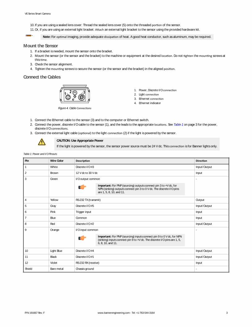
Figure 4. Cable Connections
1. Power, Discrete I/O connection2. Light connection3. Ethernet connection4. Ethernet indicator
1. Connect the Ethernet cable to the sensor (3) and to the computer or Ethernet switch.2. Connect the power, discrete I/O cable to the sensor (1), and the leads to the appropriate locations. See Table 1 on page 3 for the power,
discrete I/O connections.3. Connect the external light cable (optional) to the light connection (2) if the light is powered by the sensor.
CAUTION: Use Appropriate Power
If the light is powered by the sensor, the sensor power source must be 24 V dc. This connection is for Banner lights only.
Table 1: Power and I/O Pinouts
Pin Wire Color Description Direction
1 White Discrete I/O #3 Input/Output
2 Brown 12 V dc to 30 V dc Input
3 Green I/O output common
Important: For PNP (sourcing) outputs connect pin 3 to +V dc, forNPN (sinking) outputs connect pin 3 to 0 V dc. The discrete I/O pinsare 1, 5, 8, 10, and 11.
-
4 Yellow RS-232 TX (transmit) Output
5 Gray Discrete I/O #5 Input/Output
6 Pink Trigger input Input
7 Blue Common Input
8 Red Discrete I/O #2 Input/Output
9 Orange I/O input common
Important: For PNP (sourcing) inputs connect pin 9 to 0 V dc, for NPN(sinking) inputs connect pin 9 to +V dc. The discrete I/O pins are 1, 5,6, 8, 10, and 11.
-
10 Light Blue Discrete I/O #4 Input/Output
11 Black Discrete I/O #1 Input/Output
12 Violet RS-232 RX (receive) Input
Shield Bare metal Chassis ground -
VE Series Smart Camera
P/N 191667 Rev. F www.bannerengineering.com - Tel: +1-763-544-3164 3
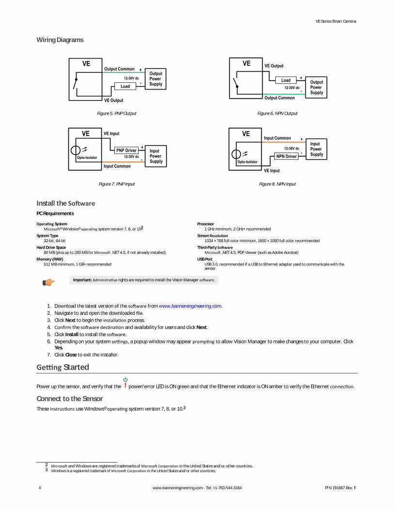
Wiring Diagrams
VE
Load
+
-12-30V dc
Output Power Supply
Output Common
VE Output
Figure 5. PNP Output
VE
+
-12-30V dc
Output Common
VE Output
Load Output Power Supply
Figure 6. NPN Output
VE
Input Common
+
-
VE Input
Opto-isolator 12-30V dcPNP Driver Input
Power Supply
Figure 7. PNP Input
VE Input Common +
-
VE Input
12-30V dc
Opto-isolator
InputPower Supply NPN Driver
Figure 8. NPN Input
Install the SoftwarePC Requirements
Operating SystemMicrosoft® Windows® operating system version 7, 8, or 102
System Type32-bit, 64-bit
Hard Drive Space80 MB (plus up to 280 MB for Microsoft .NET 4.5, if not already installed)
Memory (RAM)512 MB minimum, 1 GB+ recommended
Processor1 GHz minimum, 2 GHz+ recommended
Screen Resolution1024 × 768 full color minimum, 1650 × 1050 full color recommended
Third-Party SoftwareMicrosoft .NET 4.5, PDF Viewer (such as Adobe Acrobat)
USB PortUSB 3.0, recommended if a USB to Ethernet adapter used to communicate with thesensor
Important: Administrative rights are required to install the Vision Manager software.
1. Download the latest version of the software from www.bannerengineering.com.2. Navigate to and open the downloaded file.3. Click Next to begin the installation process.4. Confirm the software destination and availability for users and click Next.5. Click Install to install the software.6. Depending on your system settings, a popup window may appear prompting to allow Vision Manager to make changes to your computer. Click
Yes.7. Click Close to exit the installer.
Getting Started
Power up the sensor, and verify that the power/error LED is ON green and that the Ethernet indicator is ON amber to verify the Ethernet connection.
Connect to the SensorThese instructions use Windows® operating system version 7, 8, or 10.3
2 Microsoft and Windows are registered trademarks of Microsoft Corporation in the United States and/or other countries.3 Windows is a registered trademark of Microsoft Corporation in the United States and/or other countries.
VE Series Smart Camera
4 www.bannerengineering.com - Tel: +1-763-544-3164 P/N 191667 Rev. F
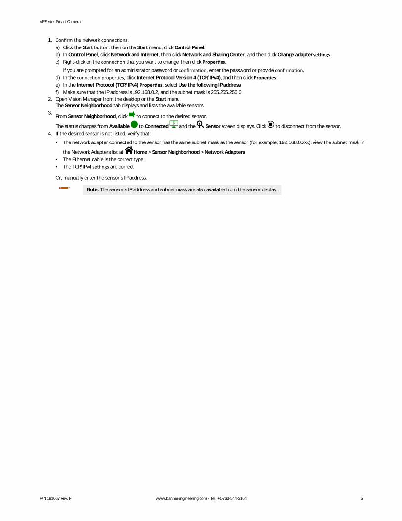
1. Confirm the network connections.a) Click the Start button, then on the Start menu, click Control Panel.b) In Control Panel, click Network and Internet, then click Network and Sharing Center, and then click Change adapter settings.c) Right-click on the connection that you want to change, then click Properties.
If you are prompted for an administrator password or confirmation, enter the password or provide confirmation.d) In the connection properties, click Internet Protocol Version 4 (TCP/IPv4), and then click Properties.e) In the Internet Protocol (TCP/IPv4) Properties, select Use the following IP address.f) Make sure that the IP address is 192.168.0.2, and the subnet mask is 255.255.255.0.
2. Open Vision Manager from the desktop or the Start menu.The Sensor Neighborhood tab displays and lists the available sensors.
3.From Sensor Neighborhood, click to connect to the desired sensor.
The status changes from Available to Connected and the Sensor screen displays. Click to disconnect from the sensor.4. If the desired sensor is not listed, verify that:
• The network adapter connected to the sensor has the same subnet mask as the sensor (for example, 192.168.0.xxx); view the subnet mask in
the Network Adapters list at Home > Sensor Neighborhood > Network Adapters• The Ethernet cable is the correct type• The TCP/IPv4 settings are correct
Or, manually enter the sensor's IP address.
Note: The sensor's IP address and subnet mask are also available from the sensor display.
VE Series Smart Camera
P/N 191667 Rev. F www.bannerengineering.com - Tel: +1-763-544-3164 5
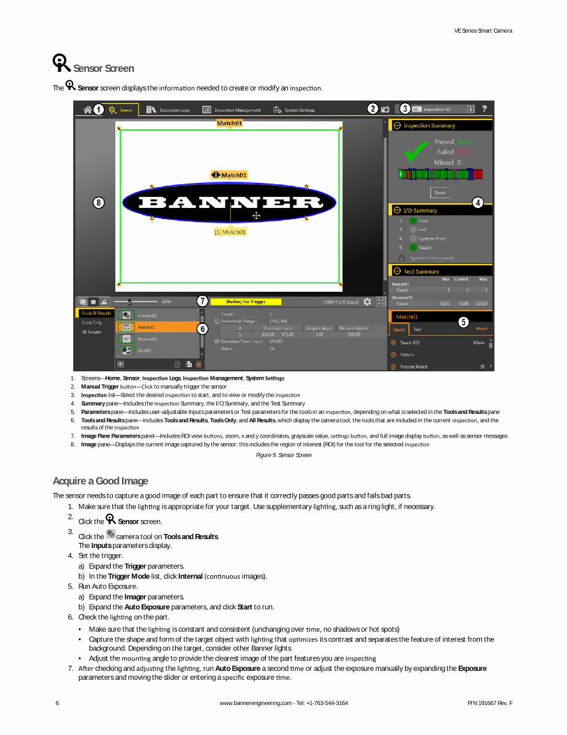
Sensor Screen
The Sensor screen displays the information needed to create or modify an inspection.
1. Screens—Home, Sensor, Inspection Logs, Inspection Management, System Settings2. Manual Trigger button—Click to manually trigger the sensor3. Inspection list—Select the desired inspection to start, and to view or modify the inspection4. Summary pane—Includes the Inspection Summary, the I/O Summary, and the Test Summary5. Parameters pane—Includes user-adjustable Inputs parameters or Test parameters for the tools in an inspection, depending on what is selected in the Tools and Results pane6. Tools and Results pane—Includes Tools and Results, Tools Only, and All Results, which display the camera tool, the tools that are included in the current inspection, and the
results of the inspection7. Image Pane Parameters panel—Includes ROI view buttons, zoom, x and y coordinates, grayscale value, settings button, and full image display button, as well as sensor messages8. Image pane—Displays the current image captured by the sensor; this includes the region of interest (ROI) for the tool for the selected inspection
Figure 9. Sensor Screen
Acquire a Good ImageThe sensor needs to capture a good image of each part to ensure that it correctly passes good parts and fails bad parts.
1. Make sure that the lighting is appropriate for your target. Use supplementary lighting, such as a ring light, if necessary.2.
Click the Sensor screen.3.
Click the camera tool on Tools and Results.The Inputs parameters display.
4. Set the trigger.a) Expand the Trigger parameters.b) In the Trigger Mode list, click Internal (continuous images).
5. Run Auto Exposure.a) Expand the Imager parameters.b) Expand the Auto Exposure parameters, and click Start to run.
6. Check the lighting on the part.• Make sure that the lighting is constant and consistent (unchanging over time, no shadows or hot spots)• Capture the shape and form of the target object with lighting that optimizes its contrast and separates the feature of interest from the
background. Depending on the target, consider other Banner lights• Adjust the mounting angle to provide the clearest image of the part features you are inspecting
7. After checking and adjusting the lighting, run Auto Exposure a second time or adjust the exposure manually by expanding the Exposureparameters and moving the slider or entering a specific exposure time.
VE Series Smart Camera
6 www.bannerengineering.com - Tel: +1-763-544-3164 P/N 191667 Rev. F
8. Adjust the focus.a) Place the part so that the area to be focused appears in the center of the Image pane.b) Expand the Focus Info parameters.c) Make sure that the Focus Info checkbox is selected.d) Adjust the focus of the lens while monitoring the focus number.
The focus number is a number between 1 and 255. Use the Image pane to determine when the image is sharp enough, or use the focusnumber as a guide. Turn the focus ring on the lens until the focus number is at the highest possible number between 1 and 255. The focusnumber is also available on the sensor display.
Note: There is no optimal value for this number, but it can be used as a guide if you are setting up more than onesensor that are focused on the same target.
e) Tighten the locking thumbscrews to secure the lens at the desired focus.
Set Up an InspectionVision Manager allows you to set up or make changes to an inspection while the sensor is running. Changes are automatically saved as they are made.
1.From the Sensor screen, click in the upper right corner to view the inspection list.
2. Click Add New Inspection.A new inspection is added to the list, the Image pane updates, and the Tools & Results tab shows only the camera tool.
3. Add tools and adjust them as needed for the inspection.
Add a Tool1.
Click on the Tools & Results tab.The Add Tool window opens.
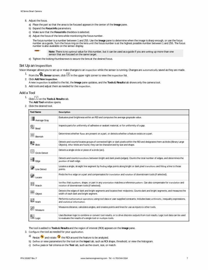
2. Click the desired tool.
Tool Name Description
Average GrayEvaluates pixel brightness within an ROI and computes the average grayscale value.
BeadInspects parts for uniformity of adhesive or sealant material, or for uniformity of a gap.
BlemishDetermines whether flaws are present on a part, or detects whether a feature exists on a part.
BlobDetects and counts/locates groups of connected light or dark pixels within the ROI and designates them as blobs (Binary LargeObjects). After blobs are found, they can be characterized by size and shape.
Circle DetectDetects a single circle or piece of a circle (arc).
EdgeDetects and counts transitions between bright and dark pixels (edges). Counts the total number of edges, and determines theposition of each edge.
Line DetectLocates a single, straight line segment by finding edge points along bright or dark pixel transitions and fitting a line to thosepoints.
LocateFinds the first edge on a part and compensates for translation and rotation of downstream tools (if selected).
MatchVerifies that a pattern, shape, or part in any orientation matches a reference pattern. Can also compensate for translation androtation of downstream tools (if selected).
ObjectDetects the edges of dark and bright segments and locates their midpoints. Counts dark and bright segments, and measures thewidth of each dark and bright segment.
MathPerforms mathematical operations using tool data or user-supplied constants. Includes basic arithmetic, inequality expressions,and statistical information.
MeasureMeasures distance, calculates angles, and creates points and lines for use as inputs to other tools.
LogicUses Boolean logic to combine or convert tool results, or to drive discrete outputs from tool results. Logic tool data can be usedto evaluate the results of a single tool or multiple tools.
The tool is added to Tools & Results and the region of interest (ROI) appears on the Image pane.3. Configure the tool as needed for your application.
a)Resize and rotate the ROI around the feature to be analyzed.
b) Define or view parameters for the tool on the Input tab, such as ROI shape, threshold, or view the histogram.c) Define pass or fail criteria on the Test tab, such as the count, size, or match.
VE Series Smart Camera
P/N 191667 Rev. F www.bannerengineering.com - Tel: +1-763-544-3164 7
Save an Inspection to a Computer, Network Drive, or Storage DeviceVision Manager automatically saves inspections to the VE as they are created and modified. Save a copy of the inspection to your computer or anothernetwork location if you want to be able to go back to previous settings.Use the following procedure to save a copy of an inspection to your computer or a network location.
1.On the Inspection Management screen, click Transfer.
2. Change the destination folder, if desired.a)
Click above the right column.An explorer window opens.
b) Navigate to the desired location, network location, or storage device.c) Click Select Folder.
The folder is selected and the window closes.The path to the location displays above the right column.
3. Select the desired inspection from the inspection list in the left column.4.
Click .Inspection name.idb displays in the right column and the inspection is transferred (saved) to the selected location.
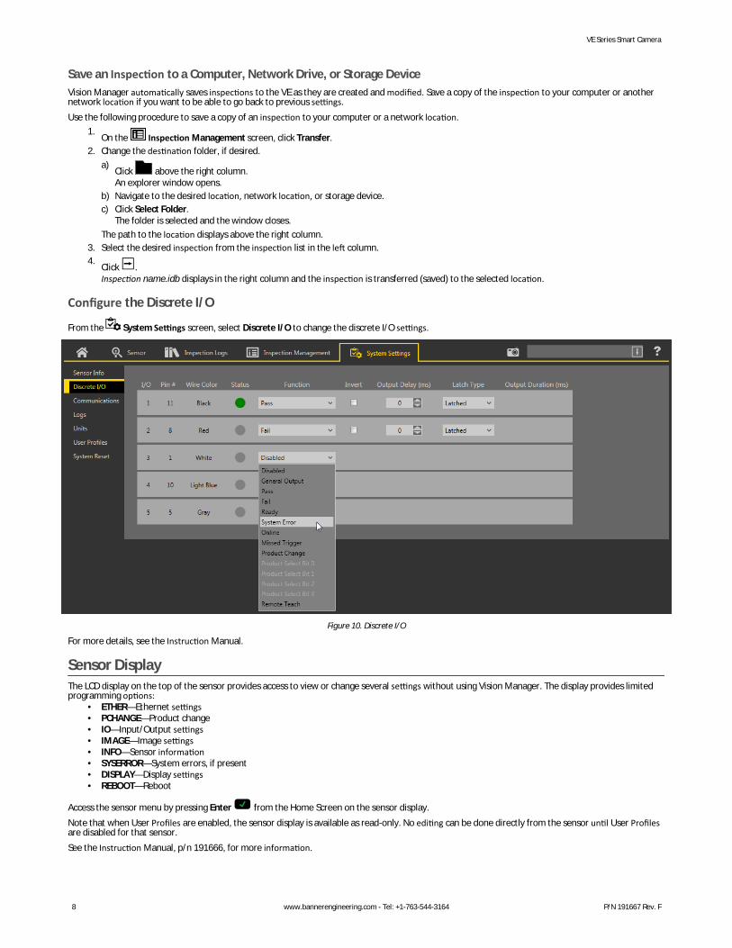
Configure the Discrete I/O
From the System Settings screen, select Discrete I/O to change the discrete I/O settings.
Figure 10. Discrete I/O
For more details, see the Instruction Manual.
Sensor DisplayThe LCD display on the top of the sensor provides access to view or change several settings without using Vision Manager. The display provides limitedprogramming options:
• ETHER—Ethernet settings• PCHANGE—Product change• IO—Input/Output settings• IMAGE—Image settings• INFO—Sensor information• SYSERROR—System errors, if present• DISPLAY—Display settings• REBOOT—Reboot
Access the sensor menu by pressing Enter from the Home Screen on the sensor display.Note that when User Profiles are enabled, the sensor display is available as read-only. No editing can be done directly from the sensor until User Profilesare disabled for that sensor.See the Instruction Manual, p/n 191666, for more information.
VE Series Smart Camera
8 www.bannerengineering.com - Tel: +1-763-544-3164 P/N 191667 Rev. F
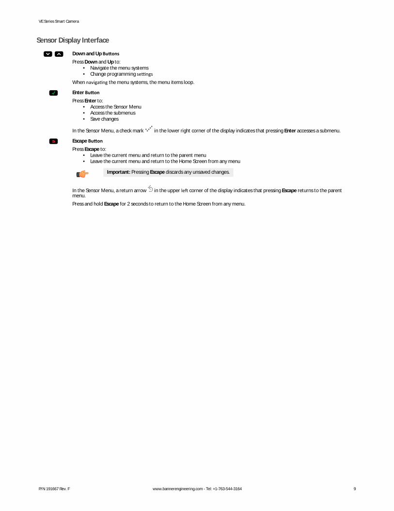
Sensor Display Interface
Down and Up ButtonsPress Down and Up to:
• Navigate the menu systems• Change programming settings
When navigating the menu systems, the menu items loop.
Enter ButtonPress Enter to:
• Access the Sensor Menu• Access the submenus• Save changes
In the Sensor Menu, a check mark in the lower right corner of the display indicates that pressing Enter accesses a submenu.
Escape ButtonPress Escape to:
• Leave the current menu and return to the parent menu• Leave the current menu and return to the Home Screen from any menu
Important: Pressing Escape discards any unsaved changes.
In the Sensor Menu, a return arrow in the upper left corner of the display indicates that pressing Escape returns to the parentmenu.Press and hold Escape for 2 seconds to return to the Home Screen from any menu.
VE Series Smart Camera
P/N 191667 Rev. F www.bannerengineering.com - Tel: +1-763-544-3164 9
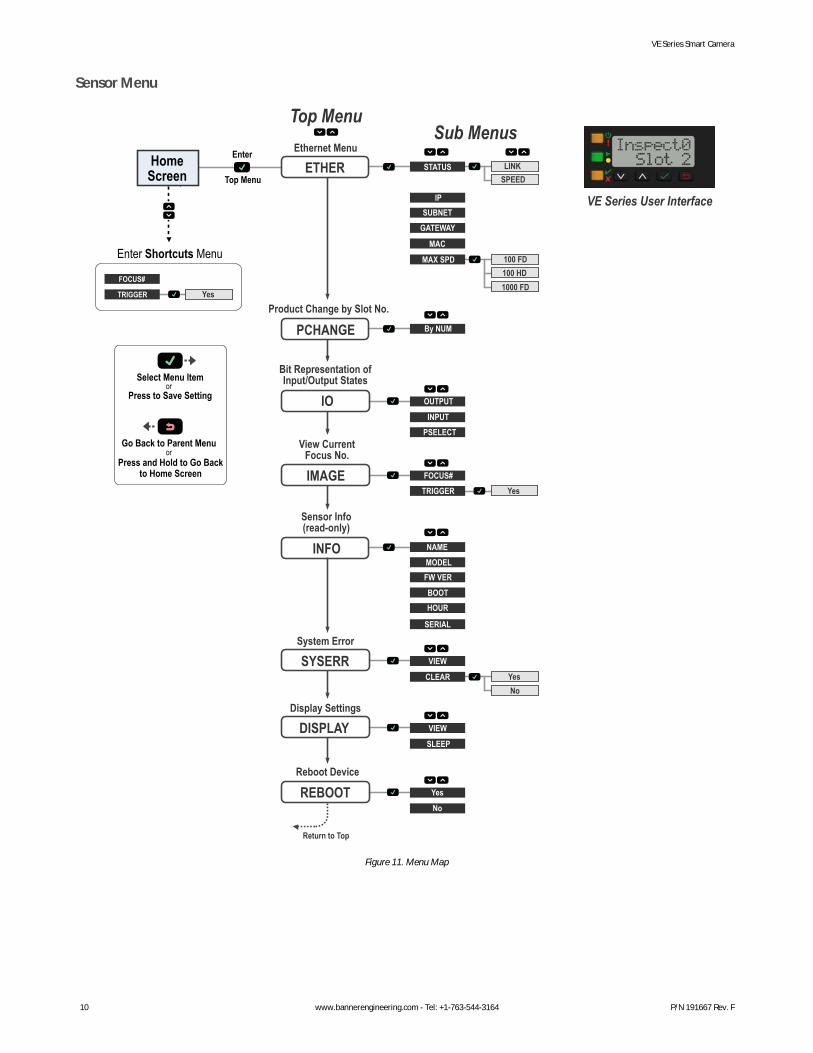
Sensor Menu
Enter Shortcuts Menu
NoYes
Yes
100 HD100 FD
FOCUS#
HomeScreen ETHER
PCHANGE
IO
VE Series User Interface
Enter
Top Menu
Top Menu
IMAGE
INFO
Sub Menus
or
or
Go Back to Parent Menu
Select Menu Item
Press to Save Setting
Press and Hold to Go Backto Home Screen
SPEEDLINK
SUBNETGATEWAY
STATUS
IP
PSELECT
TRIGGER
INPUT
MAC
MAX SPD
By NUM
OUTPUT
FW VER
BOOT
NAMEMODEL
HOUR
SERIAL
SLEEP
VIEW
Ethernet Menu
Product Change by Slot No.
Bit Representation ofInput/Output States
View CurrentFocus No.
Sensor Info(read-only)
DISPLAYDisplay Settings
CLEAR
VIEWSYSERRSystem Error
No
YesREBOOTReboot Device
Return to Top
Yes
FOCUS#
TRIGGER1000 FD
Figure 11. Menu Map
VE Series Smart Camera
10 www.bannerengineering.com - Tel: +1-763-544-3164 P/N 191667 Rev. F
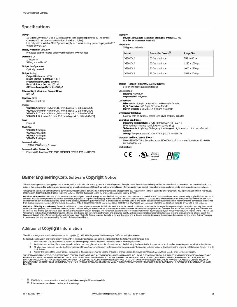
SpecificationsPower
12 V dc to 30 V dc (24 V dc ± 10% if a Banner light source is powered by the sensor)Current: 400 mA maximum (exclusive of load and lights)Use only with a suitable Class 2 power supply, or current limiting power supply rated 12V dc to 30 V dc, 1 A
Supply Protection CircuitryProtected against reverse polarity and transient overvoltages
Discrete I/O1 Trigger IN5 Programmable I/O
Output ConfigurationOptically isolated
Output RatingOutput Resistance: < 2 ΩStrobe Output Resistance: < 13 ΩProgrammable Output: 100 mAExternal Strobe Output: 100 mAOff-State Leakage Current: < 100 µA
External Light Maximum Current Draw600 mA
Exposure Time0.02 ms to 500 ms
ImagerVE200G1A: 6.9 mm × 5.5 mm, 8.7 mm diagonal (1/1.8-inch CMOS)VE201G1A: 6.9 mm × 5.5 mm, 8.7 mm diagonal (1/1.8-inch CMOS)VE202G*A: 7.2 mm × 5.4 mm, 9.0 mm diagonal (1/1.8-inch CMOS)VE205G1A 12.4 mm × 9.8 mm, 15.9 mm diagonal (1/1.8-inch CMOS)
LensC-mount
Pixel SizeVE200G1A: 5.3 µmVE201G1A: 5.3 µmVE202G*A: 4.5 µmVE205G1A: 4.8 µm
Communication10/100/10004 Mbps Ethernet
Communication ProtocolsEthernet/IP, Modbus/TCP, PCCC, PROFINET, TCP/IP, FTP, and RS-232
MemoryDevice Settings and Inspection Storage Memory: 500 MBNumber of inspection files: 999
Acquisition256 grayscale levels
Model Frames Per Second5 Image Size
VE200G1A 60 fps, maximum 752 × 480 px
VE201G1A 60 fps, maximum 1280 × 1024 px
VE202G*A 50 fps, maximum 1600 × 1200 px
VE205G1A 22 fps, maximum 2592 × 2048 px
Torque—Tapped Holes for Mounting Screws8 lbf·in (0.9 N·m) maximum torque
ConstructionHousing: AluminumDisplay Label: Polyester
ConnectionsEthernet: M12, 8-pin or 4-pin D-code Euro-style femaleLight Connector: M8, 3-pin Pico-style femalePower, Discrete I/O: M12, 12-pin Euro-style male
Environmental RatingIEC IP67 with an optional sealed lens cover properly installed
Operating ConditionsOperating Temperature: 0 °C to +50 °C (+32 °F to +122 °F)95% maximum relative humidity (non-condensing)Stable Ambient Lighting: No large, quick changes in light level; no direct or reflectedsunlightStorage Temperature: –30 °C to +70 °C (–22 °F to +158 °F)
Vibration and Mechanical ShockMeets EN 60947-5-2: 30 G Shock per IEC 60068-2-27; 1 mm amplitude from 10 - 60 Hzper IEC 60068-2-6
Certifications
InformationTechnologyEquipment
E365235
Banner Engineering Corp. Software Copyright NoticeThis software is protected by copyright, trade secret, and other intellectual property laws. You are only granted the right to use the software and only for the purposes described by Banner. Banner reserves all otherrights in this software. For so long as you have obtained an authorized copy of this software directly from Banner, Banner grants you a limited, nonexclusive, nontransferable right and license to use this software.
You agree not to use, nor permit any third party to use, this software or content in a manner that violates any applicable law, regulation or terms of use under this Agreement. You agree that you will not reproduce,modify, copy, deconstruct, sell, trade or resell this software or make it available to any file-sharing or application hosting service.Disclaimer of Warranties. Your use of this software is entirely at your own risk, except as described in this agreement. This software is provided "AS-IS." To the maximum extent permitted by applicable law, Banner, itaffiliates, and its channel partners disclaim all warranties, expressed or implied, including any warranty that the software is fit for a particular purpose, title, merchantability, data loss, non-interference with or non-infringement of any intellectual property rights, or the accuracy, reliability, quality or content in or linked to the services. Banner and its affiliates and channel partners do not warrant that the services are secure, freefrom bugs, viruses, interruption, errors, theft or destruction. If the exclusions for implied warranties do not apply to you, any implied warranties are limited to 60 days from the date of first use of this software.Limitation of Liability and Indemnity. Banner, its affiliates and channel partners are not liable for indirect, special, incidental, punitive or consequential damages, damages relating to corruption, security, loss or theftof data, viruses, spyware, loss of business, revenue, profits, or investment, or use of software or hardware that does not meet Banner minimum systems requirements. The above limitations apply even if Banner andits affiliates and channel partners have been advised of the possibility of such damages. This Agreement sets forth the entire liability of Banner, its affiliates and your exclusive remedy with respect to the software use.You agree to indemnify and hold Banner and its affiliates and channel partners harmless from any and all claims, liability and expenses, including reasonable attorney's fees and costs, arising out of your use of theServices or breach of this Agreement (collectively referred to as "Claims"). Banner reserves the right at its sole discretion and at its own expense, to assume the exclusive defense and control of any Claims. You agreeto reasonably cooperate as requested by Banner in defense of any Claims.
Additional Copyright InformationThe Vision Manager software includes code that is copyright (c) 1985, 1989 Regents of the University of California. All rights reserved.Redistribution and use in source and binary forms, with or without modification, are permitted provided that the following conditions are met:
1. Redistributions of source code must retain the above copyright notice, this list of conditions and the following disclaimer.2. Redistributions in binary form must reproduce the above copyright notice, this list of conditions and the following disclaimer in the documentation and/or other materials provided with the distribution.3. All advertising materials mentioning features or use of this software must display the following acknowledgement: This product includes software developed by the University of California, Berkeley and its
contributors.4. Neither the name of the University nor the names of its contributors may be used to endorse or promote products derived from this software without specific prior written permission.
THIS SOFTWARE IS PROVIDED BY THE REGENTS AND CONTRIBUTORS ``AS IS'' AND ANY EXPRESS OR IMPLIED WARRANTIES, INCLUDING, BUT NOT LIMITED TO, THE IMPLIED WARRANTIES OF MERCHANTABILITY ANDFITNESS FOR A PARTICULAR PURPOSE ARE DISCLAIMED. IN NO EVENT SHALL THE REGENTS OR CONTRIBUTORS BE LIABLE FOR ANY DIRECT, INDIRECT, INCIDENTAL, SPECIAL, EXEMPLARY, OR CONSEQUENTIALDAMAGES (INCLUDING, BUT NOT LIMITED TO, PROCUREMENT OF SUBSTITUTE GOODS OR SERVICES; LOSS OF USE, DATA, OR PROFITS; OR BUSINESS INTERRUPTION) HOWEVER CAUSED AND ON ANY THEORY OFLIABILITY, WHETHER IN CONTRACT, STRICT LIABILITY, OR TORT (INCLUDING NEGLIGENCE OR OTHERWISE) ARISING IN ANY WAY OUT OF THE USE OF THIS SOFTWARE, EVEN IF ADVISED OF THE POSSIBILITY OF SUCHDAMAGE.
4 1000 Mbps communication speed not available on 4-pin Ethernet models5 This value can vary based on inspection settings.
VE Series Smart Camera
P/N 191667 Rev. F www.bannerengineering.com - Tel: +1-763-544-3164 11

Banner Engineering Corp. Limited WarrantyBanner Engineering Corp. warrants its products to be free from defects in material and workmanship for one year following the date of shipment. Banner Engineering Corp. will repair or replace, free of charge, anyproduct of its manufacture which, at the time it is returned to the factory, is found to have been defective during the warranty period. This warranty does not cover damage or liability for misuse, abuse, or theimproper application or installation of the Banner product.THIS LIMITED WARRANTY IS EXCLUSIVE AND IN LIEU OF ALL OTHER WARRANTIES WHETHER EXPRESS OR IMPLIED (INCLUDING, WITHOUT LIMITATION, ANY WARRANTY OF MERCHANTABILITY OR FITNESS FOR APARTICULAR PURPOSE), AND WHETHER ARISING UNDER COURSE OF PERFORMANCE, COURSE OF DEALING OR TRADE USAGE.This Warranty is exclusive and limited to repair or, at the discretion of Banner Engineering Corp., replacement. IN NO EVENT SHALL BANNER ENGINEERING CORP. BE LIABLE TO BUYER OR ANY OTHER PERSON ORENTITY FOR ANY EXTRA COSTS, EXPENSES, LOSSES, LOSS OF PROFITS, OR ANY INCIDENTAL, CONSEQUENTIAL OR SPECIAL DAMAGES RESULTING FROM ANY PRODUCT DEFECT OR FROM THE USE OR INABILITY TOUSE THE PRODUCT, WHETHER ARISING IN CONTRACT OR WARRANTY, STATUTE, TORT, STRICT LIABILITY, NEGLIGENCE, OR OTHERWISE.Banner Engineering Corp. reserves the right to change, modify or improve the design of the product without assuming any obligations or liabilities relating to any product previously manufactured by BannerEngineering Corp. Any misuse, abuse, or improper application or installation of this product or use of the product for personal protection applications when the product is identified as not intended for such purposeswill void the product warranty. Any modifications to this product without prior express approval by Banner Engineering Corp will void the product warranties. All specifications published in this document are subjectto change; Banner reserves the right to modify product specifications or update documentation at any time. Specifications and product information in English supersede that which is provided in any other language.For the most recent version of any documentation, refer to: www.bannerengineering.com.
VE Series Smart Camera
© Banner Engineering Corp. All rights reserved


![NXP Secure Smart Card Controller P60x017/041PVE · IC Hardware NXP Secure Smart Card Controller P60x017/041PVE VE [12 November 2014] wafer, module, inlay, package (dice have nameplate](https://img.pdfslide.us/doc/110x75/5ed52fe9e8bd062776696943/nxp-secure-smart-card-controller-p60x017041pve-ic-hardware-nxp-secure-smart-card.jpg)