Embed Size (px)
Citation preview

ASHRAE 90.1 Appendix G - PRM
VE-Gaia PRM NavigatorPerformance Rating Method
By:INTEGRATED ENVIRONMENTAL SOLUTIONS LIMITEDDevelopers of the IES <Virtual Environment>
Date: June 2010
A New Approach to
BOSTON, MA │ GLASGOW, SCOTLAND │ DUBLIN, IRELAND │ LONDON, ENGLAND │ MELBOURNE, AUSTRALIA │ SAN FRANCISCO, CA │ DUBAI, UAE
Energy Modelling

Contents
Page 2
Performance Rating Method
VE-Gaia: PRM Navigator Introduction.................................................................................................. 5
VE-Gaia: PRM Navigator – What makes it different?........................................................................... 5
VE-Gaia: ASHRAE 90.1 App-G PRM Navigator Structure ................................................................... 5
VE-Pro Modules to utilize with PRM Navigator................................................................................. 6
Preliminary Data Setup ........................................................................................................................ 8
Workflow concept ............................................................................................................................. 9
Site, Location and Climate................................................................................................................ 9
Prototype Data (ASHRAE Baseline) ............................................................................................... 10
Fossil Fuel Type ............................................................................................................................. 11
Update Profile Working Week Order............................................................................................... 11
Building Geometry .......................................................................................................................... 12
Settings ....................................................................................................................................... 12
Input Options............................................................................................................................... 16
Site Obstructions & Shading........................................................................................................... 19
Input Options............................................................................................................................... 19
Set Selected Zones to Obstructions............................................................................................ 19
Building Orientation ........................................................................................................................ 20
Room/Zone Group Assignment ...................................................................................................... 20
Solar Shading Calculation .............................................................................................................. 24
Envelope Thermo-Physical Properties ............................................................................................... 25
ASHRAE Baseline Constructions ................................................................................................... 25
Proposed Building Constructions.................................................................................................... 26
Improve Baseline ........................................................................................................................ 26
Custom Construction Type.......................................................................................................... 27
Surface Assignment........................................................................................................................ 27
Above Ground............................................................................................................................. 27
Below Ground ............................................................................................................................. 27
Room/Zone Thermal Template Data.................................................................................................. 28
Space Classification ....................................................................................................................... 28
Room Conditions (set-points) ......................................................................................................... 28
Internal Heat Gains......................................................................................................................... 30
Equipment................................................................................................................................... 30
People......................................................................................................................................... 30
Lighting ....................................................................................................................................... 30

Contents
Page 3
Performance Rating Method
ASHRAE 62.1 Parameters ............................................................................................................. 32
Air Exchange .................................................................................................................................. 33
IAQ (Outside Air)......................................................................................................................... 33
Infiltration .................................................................................................................................... 34
Other End Uses .............................................................................................................................. 35
Exterior Lighting .......................................................................................................................... 35
Elevators ..................................................................................................................................... 36
Service Hot Water ....................................................................................................................... 37
HVAC Systems .................................................................................................................................. 38
Baseline System............................................................................................................................. 38
Edit Current Baseline .................................................................................................................. 38
Assign Rooms............................................................................................................................. 40
AHU System Parameters ............................................................................................................ 40
Proposed System ........................................................................................................................... 41
Improve Upon Baseline............................................................................................................... 41
Edit Current Proposed................................................................................................................. 41
OR Custom System .................................................................................................................... 41
Assign Rooms............................................................................................................................. 41
AHU System Parameters ............................................................................................................ 41
System Schedules.......................................................................................................................... 41
Performance Curve Data ................................................................................................................ 42
Other Input Data................................................................................................................................. 43
Renewable Energy Systems........................................................................................................... 43
Utility Tariffs.................................................................................................................................... 44
Fossil Fuel Type ............................................................................................................................. 44
Generate Baseline.............................................................................................................................. 46
Generate the Baseline Model ......................................................................................................... 46
Sizing Runs ........................................................................................................................................ 48
Room Load Calculations................................................................................................................. 48
Assign Room Sizing Data ............................................................................................................... 49
System Load Calculations .............................................................................................................. 49
Assign System Sizing Data............................................................................................................. 49
Sizing Reports ................................................................................................................................ 50
Proposed..................................................................................................................................... 50
Baseline 0°.................................................................................................................................. 52
Baseline 90°................................................................................................................................ 52

Contents
Page 4
Performance Rating Method
Baseline 180°.............................................................................................................................. 52
Baseline 270°.............................................................................................................................. 52
Simulations......................................................................................................................................... 53
Proposed Model Simulation............................................................................................................ 53
0° Baseline Model Simulation ......................................................................................................... 53
Full PRM Simulation ....................................................................................................................... 53
Results ............................................................................................................................................... 54
BPRM Report ................................................................................................................................. 54
User Details ................................................................................................................................ 54
Data Tables 1.3 and 1.4.............................................................................................................. 55
Cost Savings Summary – Table 1.8.2(b) .................................................................................... 56
Energy Savings Summary – Table 1.8.2..................................................................................... 56
Baseline Costs – Table 1.8.1(b).................................................................................................. 57
Baseline Energy – Table 1.8.1 .................................................................................................... 57
Full Report .................................................................................................................................. 58
10 Minute Checklist ........................................................................................................................ 62
Proposed..................................................................................................................................... 62
Baseline 0°.................................................................................................................................. 65
Baseline 90°................................................................................................................................ 65
Baseline 180°.............................................................................................................................. 65
Baseline 270°.............................................................................................................................. 66
Display Selected Reports ............................................................................................................... 66

VE-Gaia: ASHRAE 90.1 App-G PRM Navigator
Page 5
Performance Rating Method
VE-Gaia: PRM Navigator Introduction
VE-Gaia = Step-by -step analysis workflows - - VE-Gaia’s complete workflow environment isdriven by “step-by-step” smart navigation that opens wide the power of IES analysis. A series ofNavigators guide users through a range of tasks; from advanced modelling, to energy/carbonanalysis, to LEED and Green Star credit interrogation and report creation
VE-Gaia: PRM Navigator – What makes it different?
The PRM Navigator establishes a ‘workflow concept’ to guide the user through the PerformanceRating Method process. It particularly targets the USGBC LEED Energy & Atmosphere Credit 1 –Optimize Energy Performance energy modeling process, however it can be used in a number ofother ways as well. For example, the following Green Rating Systems (but not limited to) that areused in different parts of the world also point to ASHRAE 90.1 Appendix G – PRM process as therequirement for energy credits as well:
- LEED Canada (points to ASHRAE 90.1-2007)- Estidama (points to ASHRAE 90.1-2007)- LEED India (points to ASHRAE 90.1-2004*)
*template data within the PRM navigator is based on 90.1-2007 version, so user will currently need toedit the input assumptions to run analysis for a different version of ASHRAE 90.1.
What makes it different from other tools that are used for energy modeling?- It could be generally categorized as a wizard, but it’s a ‘smart navigator’: The PRM
Navigator not only allows users to implement and manage the PRM process in a new way italso ‘navigates’ how the user can access the different VE-Pro modules required (see requiredmodule list below) to complete the different types of analysis involved in the PRM process in astreamlined manner. The user is also given real-time feedback along the way so they cancompare how their design stacks up to the 90.1 requirements.
- 5 in 1: All five models (proposed design + 4 baseline models) required for the PRM live in onefile versus having to maintain the data across five different model files.
- Input Data Once and Manage Edits effectively: The manner in which inputs are handledallows the user to input the data within the model, which influences the inputs in all fivemodels.
- Creating the Baseline Models: The required baseline models are generated from theproposed design filtered through the requirements of ASHRAE 90.1 Appendix G, at the stagein the process the user chooses to develop them. The user has two choices…
VE-Gaia: ASHRAE 90.1 App-G PRM Navigator Structure
The main objectives of the VE-Gaia PRM (Performance Rating Method) Navigator are to:
1. Manage the overall process, including inputs, edits and cycles of the PRM (ASHRAE 90.1Appendix G)
2. Provide industry recognized defaults and input selection options (ASHRAE standards dataas the basis) to assist the process

VE-Gaia: ASHRAE 90.1 App-G PRM Navigator
Page 6
Performance Rating Method
A range of individual software modules and features are available within the VE-Pro suite which canbe used to construct a detailed PRM model. The user needs to manually switch between modulesand know at which point in the process a specific feature needs to be used. In summary it can bedifficult to understand how each module and feature fits into the overall PRM workflow analysisprocess.
The VE-Gaia PRM Navigator is a tool which brings all of the individual VE-Pro modules and featurestogether in a single area and presents the user with step-by-step smart navigation and managementof the PRM workflow and analysis process. The Navigator is driven through the successful executionof specific actions and commands which are activated by the user in a defined sequence.
This smart navigation leads the user through the process of basic geometry creation, toconstructions/thermal data assignment, and ultimately to the automatic generation of a full set ofPRM compliant results which are presented in a format similar to the LEED EAc1 Letter Template.
The Navigator also provides the user with predefined prototypical ASHARE data which can be usedto populate the model with default baseline information.
The main structure of the PRM Navigator workflow includes:1. Preliminary Data setup2. Envelope Thermo/Physical Properties3. Room/Zone Thermal Template Data4. HVAC systems5. Other Input Data6. Generate Baseline7. Sizing runs8. Simulations9. Results
The ASHRAE 90.1 App – G PRM Navigator functions as a series of hyperlinks that are accessedwithin the smart navigator tree structure that is located on the upper left side of the interface. Thehyperlinks take the user to the relevant VE-Pro module and dialog box to complete the tasksassociated with that topic.
Note: that the user can increase the size of this area by dragging downward on the borderbetween the VE-Gaia workflows area and the Rooms area.
VE-Pro Modules to utilize with PRM NavigatorThe following list of VE-Pro modules are classified into two categories – required and beneficial. It isrecommended that the user confirm which VE-Pro modules they have licenses for, so that they havethe full capability of the PRM navigator available.
Required:o ModelITo Suncasto ApacheSimo ApacheLoadso ApacheHVAC
Beneficial Based on what type of efficiency measures or HVAC system is being analyzed:

VE-Gaia: ASHRAE 90.1 App-G PRM Navigator
Page 7
Performance Rating Method
o FlucsPro, LightPro, Radianceo Macroflo
Figure 1 provides an over of the Virtual Environment software platform. The upper right portion of thediagram identifies the four tiers of the VE comprised of:
- VE-Ware- VE-Toolkits- VE-Gaia- VE-Pro
For additional information on the four levels go to “How and when should I integrate performanceanalysis for sustainable design?”
The lower portion of Figure 1 identifies the different modules that a part of VE-Pro. For additionalinformation on the different modules please go to - http://www.iesve.com/Software/VE-Pro
Figure 1 - The Four Levels of the VE and VE-Pro Modules

VE-Gaia: ASHRAE 90.1 App-G PRM Navigator
Page 8
Performance Rating Method
Preliminary Data Setup
Figure 2 - Preliminary Data Setup Sub-Categories and Tasks
A few things to note that are consistent across all the sub tasks for each of the nine main categoryareas with the navigator
Figure 3 - Task Button Options
Each task line will have up to three buttons shown to the right:- ? – provides a link to ‘help files’ directly related to that task line- Notes icon – when selected a ‘notes field’ will appear below, which allows the user to input
specific notes related to that task for documentation purposes or to share with other teammembers
- Check box – provides users the ability to select and ‘check’ that task as complete. This canbe important for personal or team tracking on a large or complex project.

VE-Gaia: ASHRAE 90.1 App-G PRM Navigator
Page 9
Performance Rating Method
Workflow conceptThe hyperlink serves a ‘help guide’ and takes the user to a more detailed description of the workflowconcept for the navigator, similar to the information contained within this document.
Site, Location and ClimateThe hyperlink for this action opens the ApLocate sub-program from which the user then specifies theglobal location of the building (Lat.>Lon.), external design conditions and simulation weather file. Thisprocess is driven by clicking on the ‘Selection Wizard...’ and following the necessary steps:
Figure 4 - Location Selection
There are four tabs associated with this dialog box: Location & Site Data – there are two options for selecting (Selection Wizard or Set Location
Only) the climate file associated with the project.

VE-Gaia: ASHRAE 90.1 App-G PRM Navigator
Page 10
Performance Rating Method
Design Weather Data – provides feedback on the climate selected and the ability to reviewand customize key parameters of the climate selected. This data will be used for the SizingRuns.
Simulation Weather Data – Reports the weather file that ApacheSim will be utilizing forsimulation runs. The file is selected based on the choices within Location & SiteData/Selection Wizard, however the user can also change the selection within this tab tobrowse and select a different weather file. This data will be used for the annualthermal/energy simulations.
Simulation Calendar – provides the ability to select and customize ‘a holiday template’ (daysconsidered to be holidays which could trigger different building operation setting) based on thecountry and other parameters.
Once the location is selected the climate file, which provides the input data for the hourly energy(8,760 hours) is determined. The VE actually runs the energy analysis on 6-minute time steps (as adefault) versus hourly, so that the influence of thermal mass can be accounted for within the design.
Prototype Data (ASHRAE Baseline)
This command imports an ASHRAE 90.1 baseline data set which can then be used as a startingpoint for any PRM project. When the command is activated the software automatically imports arange of default ASHRAE data in a fully functional VE format. This allows a user to define the buildingbased on the building type (for early stage analysis) or space type (for more detailed analysis):
ASHRAE 90.1 Thermal Templates (Building Area Method or Space by Space Method)For the Building Area Method, default data is derived from:
o ASHRAE 90.1 Internal Gains (Occupancy, Lighting, Equipment) For the Space by Space Method, default data is derived from:
o ASHRAE 90.1 Lighting power densitieso ASHRAE 62.1 Occupancy densitieso Title 24 ACM Equipment power densities
Both methods useo ASHRAE 90.1 Profiles/Schedules (from the User’s manual)o ASHRAE 62.1 Outdoor fresh air rateso ASHRAE 90.1 Envelope/Fabric Data (ASHRAE Climate Zone specific)o ASHRAE 90.1 Baseline Systems (1 to 8 +)
All of these defaults are editable to suit your actual project through subsequent steps of the navigator.After the Navigator command has been activated the user must then select the “90_1_2007_IP”folder and subsequently select the associated VE .mit file.

VE-Gaia: ASHRAE 90.1 App-G PRM Navigator
Page 11
Performance Rating Method
Figure 5 - Prototype Data Templates
Fossil Fuel Type
This command allows the user to select the appropriate fuel type per energy use which will besubsequently used in the automatic generation of PRM results reportage in the Results section of theNavigator. This step is only important if these energy end uses are served by fossil fuels. If they areserved by electricity and assigned the appropriate fuel code, this step is not necessary.
Figure 6 - Fossil Fuel Type Dialog Box
Update Profile Working Week Order
The hyperlink takes the user to the ‘Profile Weekly Pattern Editor’ which is used to dictate the dailyoperation of the building at a daily/weekly level. It allows the user to customize the operational daysof their building to match the project requirements.
For example, in the Middle East region the typical working week is Sun-Thu with Fri/Sat being theweekend. In the UK/US however the working week is Mon-Fri with Sat/Sun being the weekend. Thisdialog allows the user to customise the weekly operation of their building.
An on/off filter is included which allows the weekday order re-shuffle/override to only be assigned toselected Profiles. The ‘All’ check-box allows a quick toggle to turn the entire list of profiles on/off.

VE-Gaia: ASHRAE 90.1 App-G PRM Navigator
Page 12
Performance Rating Method
Figure 7 - Profile Weekly Pattern Editor Dialog
Building Geometry
Settings
Locks
Locks allow the user to snap the drawing tool to various items in the model view window such asmodel endpoint, midpoint, grid, etc. When creating model geometry it is useful to have the lockwindow open so you can switch different locks on and off depending on the particular modeling taskyou are trying perform.

VE-Gaia: ASHRAE 90.1 App-G PRM Navigator
Page 13
Performance Rating Method
Figure 8 - Locks Dialog Box
Grid
Snapping to the grid when building model geometry ensures the creation of an accurate compactmodel which enhances accuracy and performance later in the analysis. This option allows thedistance between grid points to be set - in both the x and y direction. Checking the grid box in thelocks menu will force the drawing tool to snap to the grid. In general it is recommended to use a gridseparation distance of 4 inches (0.1m).
Figure 9 - Grid Settings dialog box
Inner Volumes
This option allows you to add or remove inner volumes from your model.

VE-Gaia: ASHRAE 90.1 App-G PRM Navigator
Page 14
Performance Rating Method
Figure 10 - Inner Volumes Dialog Box
Inner volumes are used to take account of the thickness of walls, ceilings and floors. The thickness ofthe walls will be defined later in the Apache Constructions Database. The thickness of the wall isrepresented in the model by a grey line which is offset into the room by the thickness of the wall.Inner volumes are only suitable for use in models with relatively simple geometry.
Figure 11 - Plan view of model separated into 4 inner volumes
VE-Gaia: ASHRAE 90.1 App-G PRM Navigator
Page 15
Performance Rating Method
Adjacency Separation Distance
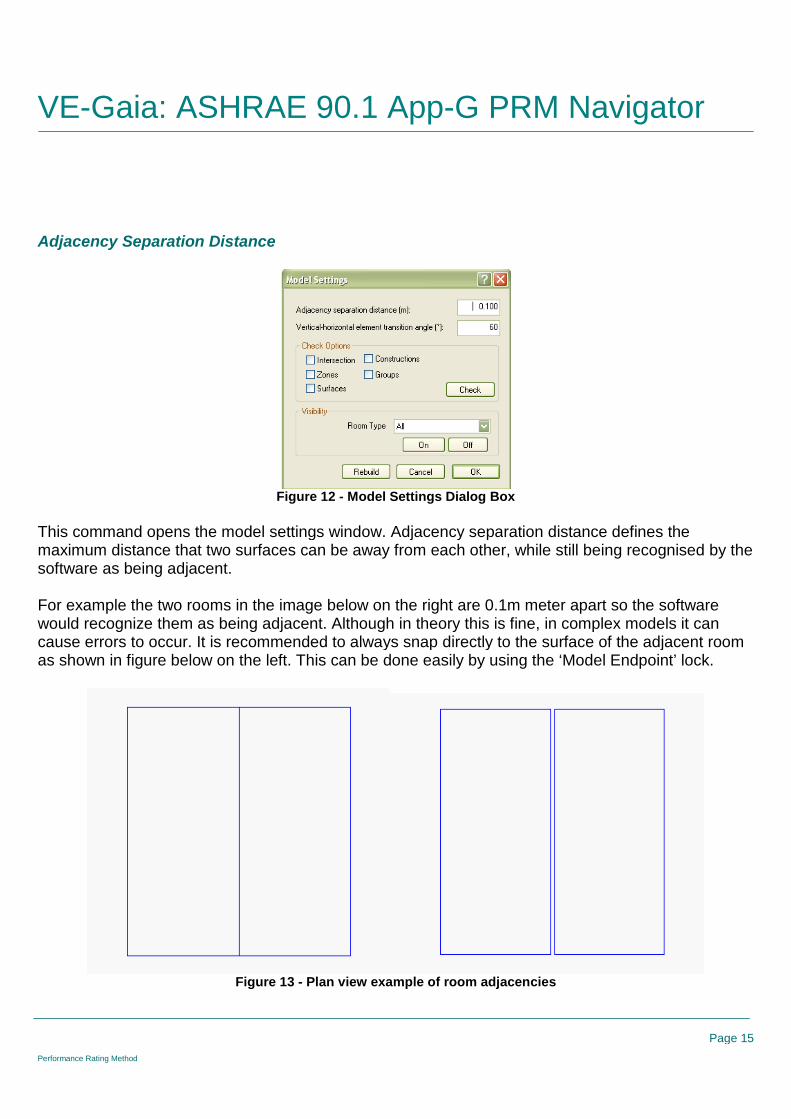
Figure 12 - Model Settings Dialog Box
This command opens the model settings window. Adjacency separation distance defines themaximum distance that two surfaces can be away from each other, while still being recognised by thesoftware as being adjacent.
For example the two rooms in the image below on the right are 0.1m meter apart so the softwarewould recognize them as being adjacent. Although in theory this is fine, in complex models it cancause errors to occur. It is recommended to always snap directly to the surface of the adjacent roomas shown in figure below on the left. This can be done easily by using the ‘Model Endpoint’ lock.
Figure 13 - Plan view example of room adjacencies

VE-Gaia: ASHRAE 90.1 App-G PRM Navigator
Page 16
Performance Rating Method
Input Options
Zoning (instructions)
Zoning is of critical importance to the model. Too many zones and the model becomes over complex, toofew and detail is lost. Although the main focus should be on capturing core functional spaces e.g. offices incommercial buildings or living rooms, bedrooms etc. in residential buildings - it is also necessary to capture thearea/volume of other miscellaneous/ancillary spaces such as elevator shafts, toilets, stairs etc.
The single most important aspect to note in relation to these space types is that they do not have to berepresented exactly and individually to effectively convey the energy consumption of the building. In otherwords it is not necessary to model each and every space separately but instead zones can be outlined aroundeach of these space types that capture all of a space type together.
The zoning (thermal block) requirements outlined in ASHRAE 90.1 Appendix G (proposed model thermalzones and baseline model thermal zones to be the same) should also be kept in mind when creating thebuilding geometry. The details presented should be followed closely in order to meet the requirements of thePerformance Rating Method.
As outlined in the concept document it is helpful that defined zones are broken-down as per the list of spacetypes used in the prototype data:
TABLE OF ROOM NAMES (from groups)
Commercial Residential
Data Center Bathroom
Elevators Bedroom
Gym Common circulation
Gym (Changing / Showers) Corridor
Kitchen Dining
Lobby Elevators
Office Kitchen
Office ceiling void Living room
Meeting Room Lobby
Parking Parking
Prayer room Services
Retail (Catering) Store
Retail (General) Void
Services
Stairs
Stores
Toilets
VoidFigure 14 - Table of Room Names
These space types correspond exactly with the room thermal templates and provide some indication of

VE-Gaia: ASHRAE 90.1 App-G PRM Navigator
Page 17
Performance Rating Method
what spaces should be grouped together.
Manually Extrude Rooms/Zones
Click the ‘draw extruded shape’ button and the ‘shape settings’ window will open. Set the height ofthe room and what plane the room sits on. You can name the room here or you can choose to namethe room later by right clicking on it in the room list in the side bar. Draw the outline of a room byclicking on points in the model view window to define the room vertices. It is important to snap to thegrid.
Figure 15 - Shape Settings Dialog for drawing shapes
Import DXF & Manually ExtrudeWhen importing a dxf it is important to select the correct scale factor. The drawing will appear in greyin the model view window and will sit behind the model. Use this to as a guide in which to trace yourrooms over while snapping to the grid at all times.
Figure 16 - Attach DXF file dialog

VE-Gaia: ASHRAE 90.1 App-G PRM Navigator
Page 18
Performance Rating Method
Import GBXML (Revit, ArchiCAD etc)
This hyperlink offers an alternative to manually building a model within the <VE> ModelIT module. Itallows a .GBXML file to be imported from another CAD platform such as ArchiCAD or other.
Note: IES has developed plug-ins (can be downloaded at www.iesve.com) for the following BIMplatforms that facilitate translating the model into the VE platform in enhanced ways compared tostraight GBXML:
SketchUp and SketchUp Pro (version 6 & 7) Revit Architecture – 2009, 2010, 2011 Revit MEP – 2008, 2009, 2010, 2011
Model Settings
The model setting window allows you to change the adjacency separation distance, vertical-horizontal element transition angle and perform model checks.
Vertical-Horizontal Element Transition angle define at what angle a wall becomes a ceiling or a floor.By default, if a surface is at an angle less than 60o it is recognized by the software as a ceiling orfloor.
Figure 17 - Model Settings Dialog Box
The model check option allows you to perform a check on the quality/integrity of the geometry in yourmodel. Check the boxes for intersections and surfaces and click the check button. A text file will becreated which will flag up any error in your model geometry. It is recommended to perform modelcheck regularly throughout the model building process. It is usually far easier to fix a geometryproblem soon after it occurs rather than at the end.
Clicking the rebuild button refreshes all the adjacencies in the model.

VE-Gaia: ASHRAE 90.1 App-G PRM Navigator
Page 19
Performance Rating Method
Site Obstructions & Shading
Input Options
Manually Extrude Rooms/Zones
This command has no specific action and simply acts as a prompt giving the user the option ofmanually extruding zones from scratch. If this is the desired option then the standard ModelIT toolbarshould be used to create zones by manually extruding in plan view. When all required zones havebeen created the Navigator check-box should be ticked confirming that the step has been completed
Import DXF & Manually Extrude
This command opens the ‘Import .dxf’ dialog and allows the user to place a .dxf as a trace layerwithin the ModelIT workspace. The user can then use the standard ModelIT commands to manuallyextrude zone geometry using the .dxf as a trace layer.
Import GBXML (Revit, ArchiCAD etc)
This command allows 3D .GBXML geometry to be imported directly from another CAD package suchas Revit or ArchiCAD.
Set Selected Zones to Obstructions
All obstruction zones (i.e. non-thermal zones) should be selected before this hyperlink isselected. By subsequently clicking on the Navigator command the following dialog will appear:
Figure 18 - Creating Obstructions Properties Dialog Box
The dialog allows the room type to be changed from “Room” to a suitable type of shading type. Thereare three types of shading:
Adjacent Building Topographical Shade Local Shade

VE-Gaia: ASHRAE 90.1 App-G PRM Navigator
Page 20
Performance Rating Method
Building Orientation
This option allows the orientation of the building to be set. The arrow points in the direction of northand adjusts when a value is entered on the input line (default position = pointing straight up).
Figure 19 - Site Rotation Angle Dialog Box
Room/Zone Group Assignment
When the prototype data is imported into the working model, it contains a series of thermal roomgroups based on ASHRAE 90.1 ‘Building Area’ & ‘Space by Space’ methods.

VE-Gaia: ASHRAE 90.1 App-G PRM Navigator
Page 21
Performance Rating Method
The prototype data also contains additional grouping schemes that may be relevant to the usersproject needs.
The ‘Word Search Grouping’ tool is used to place rooms (thermal zones) into room groups.
Figure 20 - Room Group Selection Rules Dialog Box
The grouping schemes that exist in the project must be extracted into the room group creator, byselecting ‘extract’.

VE-Gaia: ASHRAE 90.1 App-G PRM Navigator
Page 22
Performance Rating Method
Figure 21 - Import Room Grouping Scheme Dialog Box
Depending on the naming convention used, common words are placed in the ‘Room Name SearchPattern’ dialog for each group. This name search uses the Perl regular expression syntax – see theuser guide ‘PatternBasedGrouping.pdf’ for further information.
In this example the rooms have been named using the convention detailed in the ‘room / zonenames’ help section of the navigator and thus general terms like, office, retail, lobby, etc can be usedto easily sort the rooms into their appropriate group.

VE-Gaia: ASHRAE 90.1 App-G PRM Navigator
Page 23
Performance Rating Method
Figure 22 - Room Group Naming Example
Clicking ‘Apply’ then places the appropriate rooms into their associated room groups.
Figure 23 - VE Model Structure view of Room Groups
If residential rooms exist in the model, this process needs to be repeated for the ‘Space types

VE-Gaia: ASHRAE 90.1 App-G PRM Navigator
Page 24
Performance Rating Method
(Residential)’ room group.
Solar Shading Calculation
Clicking this hyperlink automatically opens the SunCast module and performs solar shadingcalculations. Solar shading calculations are performed hour by hour for the 15th day of each month ofthe year. These results will be fed into the Apache Dynamic Thermal Simulation as a simulation link.
Figure 24 - Suncast Solar Shading Calculations status dialog box

Room/Zone Thermal Template Data
Page 25
Performance Rating Method
Envelope Thermo-Physical Properties
Figure 25 - Envelope Thermo-Physical Properties Sub-categories and Tasks
This navigator category consists of a number of sub-categories and tasks designed to take usersthrough the process of assigning ASHRAE baseline & proposed building envelope information.
ASHRAE Baseline Constructions
Step 1: The user must first select the Building Type.Step 2: Subsequently both Opaque & Fenestration construction category types must then be selectedfrom the provided drop down boxes. By pushing the ‘ok’ button pre-defined construction materials willthen be imported into the ApCdb construction data base manager, with default values correspondingto the relevant ASHARE Climate Zone requirements.
Note: If a US climate zone location has been selected back in the ‘site, location & climate’ step therelevant ASHRAE 90.1 baseline construction will be automatically imported into the ApCdbconstruction data base manager’.

Room/Zone Thermal Template Data
Page 26
Performance Rating Method
Figure 26 - Baseline Construction Type Selector Dialog Box
Proposed Building ConstructionsWithin this section the user can choose to assign proposed building constructions from one of twooptions.
Improve BaselineThe user can choose to select & edit any default ASHRAE 90.1 baseline construction type for use inthe proposed model. Clicking the “Show Baseline” button will display a list of the baselineconstructions, so you can assess how your proposed construction compares to the baselinerequirements.
Figure 27 - ASHRAE Assembly Wizard Dialog Box
Improved baseline constructions for use in the proposed building can be imported into the ApCdbconstruction data base manager once manual edits have been made. Note that a copy will be madefor the proposed building and the baseline construction itself will not be edited. Clicking the “Apply”

Room/Zone Thermal Template Data
Page 27
Performance Rating Method
button will automatically assign your improved construction assembly to the entire proposed building.
Custom Construction Type
Alternatively the user can choose to create proposed building envelope constructions as per knownproject specifications. When choosing this option the user is taken straight to the ApCdb constructiondata base manager were they can create custom construction types for the proposed model fromscratch.
Figure 28 - Project Constructions Dialog Box
Note: For future reference when using the VE. The line items in the dialog above that are highlightedin green mean that those external wall types (in this case) are being used in the model.
Surface Assignment
This command allows the user to assign proposed construction types to model surfaces. Note thatbaseline constructions will be automatically assigned to the baseline model once created (later stepin the PRM Navigator Process).
Above Ground
Assign above ground proposed constructions
Below Ground
Assign below ground constructions. (As per ASHRAE 90.1 calculation method)

Room/Zone Thermal Template Data
Page 28
Performance Rating Method
Room/Zone Thermal Template Data
Figure 29 - Room/Zone Thermal Template Data - Sub-categories and Tasks
This navigator stage consists of a number of sub steps that take the user through assigning thermaltemplate information to the Proposed & baseline models.
Space Classification
This step assigns building thermal template information to the proposed model based on the selectedthermal template scheme—i.e., the Building area method or Space by space method. This step isclosely linked to the “Room/zone Group Assignment” step. Therefore, all spaces in the model mustfirst be assigned to the appropriate groups in either the BLDG or SPACE grouping schemes. This canbe done manually or with tools provided in the “Room/zone Group Assignment” step.
Note that you must decide whether to use the Building Area Method OR the Space by Space Method,not a combination of the two. If you opt for the Space by Space method, then ensure that the roomgroup assignment under the building area method is “NOT BLDG”. If you opt for the Building Areamethod, then ensure that the space by space room group assignment is “NOT SPACE”
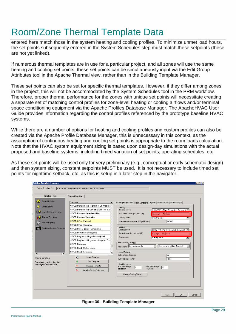
Room Conditions (set-points)
Set design heating and cooling set point temperatures for ASHRAE load calculation and HVACsystem sizing purposes.
Matching HVAC system sizing with the set points used for system controls requires that the set point
Room/Zone Thermal Template Data
Page 29
Performance Rating Method
entered here match those in the system heating and cooling profiles. To minimize unmet load hours,the set points subsequently entered in the System Schedules step must match these setpoints (theseare not yet linked).
If numerous thermal templates are in use for a particular project, and all zones will use the sameheating and cooling set points, these set points can be simultaneously input via the Edit GroupAttributes tool in the Apache Thermal view, rather than in the Building Template Manager.
These set points can also be set for specific thermal templates. However, if they differ among zonesin the project, this will not be accommodated by the System Schedules tool in the PRM workflow.Therefore, proper thermal performance for the zones with unique set points will necessitate creatinga separate set of matching control profiles for zone-level heating or cooling airflows and/or terminalspace conditioning equipment via the Apache Profiles Database Manager. The ApacheHVAC UserGuide provides information regarding the control profiles referenced by the prototype baseline HVACsystems.
While there are a number of options for heating and cooling profiles and custom profiles can also becreated via the Apache Profile Database Manager, this is unnecessary in this context, as theassumption of continuous heating and cooling set points is appropriate to the room loads calculation.Note that the HVAC system equipment sizing is based upon design-day simulations with the actualproposed and baseline systems, including timed variation of set points, operating schedules, etc.
As these set points will be used only for very preliminary (e.g., conceptual or early schematic design)and then system sizing, constant setpoints MUST be used. It is not necessary to include timed setpoints for nighttime setback, etc. as this is setup in a later step in the navigator.
Figure 30 - Building Template Manager

Room/Zone Thermal Template Data
Page 30
Performance Rating Method
Internal Heat Gains
Set Proposed internal gains.
Note: Equipment & People gains should remain the same in both the proposed & baseline models.
Equipment
Baseline & Proposed equipment loads should remain the same except in special cases. Editing thebaseline column will apply changes to both models. Editing the proposed column will only edit theproposed model and a message will appear alerting the user that differences in equipment gainsbetween the baseline and proposed must be justified with supporting documentation to the entityreviewing the energy model.
People
Baseline & Proposed equipment loads should remain the same. Editing the value in this dialog willapply the edit to both the proposed and baseline models.
Lighting
Set proposed lighting power densities for space types. The default values provided for the baselinemodel are in line with the values in ASHRAE 90.1-2007 Chapter 9 Lighting within:
Table 9.5.1 Lighting Power Densities Using the Building Area Method Table 9.6.1 Lighting Power Densities Using the Space-by-Space Method

Room/Zone Thermal Template Data
Page 31
Performance Rating Method
Figure 31 - Reduce Lighting Power - Proposed Manual Value Entry
The dialog above shows the first way that the Lighting Power Density (LPD) can be input for theProposed Design model through direct entry of a value on the far right column (LPD Proposed W/ft2)for each space type.
Note that the LPD Baseline W/ft2 default value shown for each space or building type aligns with theASHRAE 90.1-2007 Chapter 9 Lighting tables identified above.
A second approach to establishing the LPD Proposed W/ft2 is shown in the figure below. The usercan either directly enter a “% value” (1-100) in the input cell under ‘Please enter lighting reductionvalue’ or if targeting a 10% reduction can just select the ‘check box’ to the right of the input cell. Byproviding an input in either one of these ways the LPD Proposed will be derived by taking the LPDBaseline value and multiplying it by (100% - the lighting reduction %). Subsequent entries into the “%reduction” field will reduce the current proposed value by that percentage. If you desire to testalternate reductions compared to the baseline, then reset the proposed LPDs in the top section tomatch the Baseline, press OK, and then reopen the dialog and enter a new % reduction.

Room/Zone Thermal Template Data
Page 32
Performance Rating Method
Figure 32 - Reduce Lighting Power Dialog - Custom Inputs
ASHRAE 62.1 ParametersThe hyperlink opens the ASHRAE 62.1 Parameters Editor (figure below), which is composed of threetabs and shows all Building and Space options available. In the upper left hand corner the user hasthe ability to select the check box for ‘show active space types’ to isolate just those utilized within themodel. The three tabs include:
Occupancy and Ventilation – provides the parameters for each line item that serve as theinputs into the ventilation calculations for the model. The user may select an alternate 62.1occupancy category for each thermal template if they desire by picking from the drop downmenu. The “Default Occupancy” column is not editable – this is the default occupancy level asper the ASHRAE 62.1 standard for each occupancy category. The “Design Occupancy”column can be edited if your proposed building has a different occupancy. Note that anyprevious edits to occupancy under the “Internal Heat Gains” will be reflected here. Edits herewill also be reflected in the Internal Heat Gains/People window. Values for Ra and Rp arederived based on 62.1 Table 6-1.
o Percentage increase in ventilation – on the lower right side of the dialog box the usercan enter a custom value (1-100%) for the percentage increase in ventilation. Afterinputting a value and hitting ‘ok’ the percentage increase input is applied to all the lineitems included on this tab. This may be useful if the project is attempting to achieveLEED EQ Credit 2.
Exhaust Requirements - provides the parameters for each line item that serve as the inputsinto the ventilation calculations for the model. The user may select an alternate exhaust ratecategory if they desire by picking from the drop down menu. This will update the exhaust flowrates accordingly as per 62.1 Table 6-4. Edits may be applied to the “exhaust per unit” columnif this is how they are specified in Standard 62.1 (restrooms, residential kitchens). Customizedexhaust flow rates may be specified by selecting “User specified exhaust rate” as the exhaustrate category, and editing one field to specify the rate in terms of cfm/sf, ACH, or exhaust perunit/# of units. A user may also specify whether exhausted zones are served by 100% transferair or not. If “Y” is selected, that zone will not have any system supply air but will be served by

Room/Zone Thermal Template Data
Page 33
Performance Rating Method
transfer air only. Zone Air Distribution – Provides the parameters for each line item influencing the system
design and ventilation calculations. The values can be manually edited within this tab. The“Mandated Supply Air Flow” column should be edited if a zone must receive a specific numberof air changes (e.g. hospitals, laboratories, etc.). The Min SA Flow columns should be editedfor VAV spaces. Min SA can be specified in terms of % of max, or cfm/sf. If values are inputin both columns, the larger of the two will be used. The values for Ez should be input as per62.1 Table 6-2 and are based on your system design. Note that the baseline model willalways use 0.4 cfm/sf for the VAV turndown, and Ez values of 1.0 for cooling and 0.8 forheating as required by 90.1.
Note: If the user has not yet applied the ASHRAE Prototype Data using the ‘Prototype Data(ASHRAE Baseline)’ hyperlink then the ASHRAE 62.1 Parameters Editor will not appear.
Note: If the user has not yet applied zoning to the model using the hyperlink ‘Room/Zone GroupAssignment’ then when the ‘show active space types’ check box is selected all the inputs willdisappear.
Figure 33 - ASHRAE 62.1 Parameters Editor
Air ExchangeBuilding air exchanges include space ventilation rates & air infiltration ACH.
IAQ (Outside Air)Specify design fresh air rates. Note that these values will not be used unless the 62.1 calculationsare disabled in the LoadCalcsVentilation spreadsheet.

Room/Zone Thermal Template Data
Page 34
Performance Rating Method
Figure 34 - Building Template Manager - System Outside Air Supply inputs
InfiltrationSpecify design air infiltration rate ACH.
Figure 35 - Air Exchanges - Infiltration Inputs
Room/Zone Thermal Template Data
Page 35
Performance Rating Method
Other End Uses
Exterior Lighting
The hyperlink takes the user to the ‘options’ dialog box, which facilitates the calculation of the‘exterior lighting power allowance’ (baseline) and the proposed model total. The dialog is constructedbased on the requirements of ASHRAE 90.1 section 9.4.5 and is divided into two surface types –‘tradable surfaces’ and ‘non-tradable surfaces’ (similar to Table 9.4.5 within ASHRAE 90.1-2007).The units listed for each end use type are the same as those listed in ASHRAE 90.1-2007.
Baseline Total: To develop the ‘exterior lighting power allowance’ the user needs to input theappropriate values for the project in the ‘Area, Length, etc’ column. The value input here will bemultiplied by the unit value for that end use to determine the Baseline Subtotal (W). At the bottom ofthe dialog box under totals the sum of the Baseline Subtotals is reported in the Baseline Total cell.
Note: the * note express that the baseline total has an additional 5% added as per therequirements within ASHRAE 90.1, Ch.9, Sec 9.4.5.
Note: when entering values in the ‘Area, Length, etc’ column pay close attention to the unitsfor each end use line item. They vary from per location, to per linear foot to per square foot.
Note: when entering values in the cells, double click on the cell to select the overall number inblue, otherwise your entry value will be before the number that is already there. For example ifthe default value is 0.00 and the user is trying to enter ’10’,if the user only selects the cell onceversus twice and inputs ‘10’, then the value that will appear in the cell is ‘100’.
Proposed Total: Once the baseline Subtotals have been determined, the appropriate ProposedSubtotals can be entered in the last column (for each line item). In addition to the ‘Proposed Total’being calculated under the ‘Totals’ area, the ‘Tradable Surfaces’ and ‘Non-Tradable Surfaces’ totalsfor both the Baseline and Proposed are calculated as well to provide another reference point toconsider.
Please Note the two notes at the bottom of the dialog box describing where the ‘proposed total’ valueand the ‘baseline total’ value goes:
Proposed Total is applied to the internal gain “ALL:Exterior Lighting” and is assigned to the lastroom in the proposed model.
Baseline Total is applied to the internal gain”ALL:Baseline Exterior Lighting” and is assigned tothe last room in the baseline model.
Exterior lighting is controlled using a default formula profile that simulates a photo cell switch. SeeASHRAE 90.1 Section 9 for further exterior light details.
The highlighted portions of the figure below show which columns the user would input values within,and the location where the totals are reported.

Room/Zone Thermal Template Data
Page 36
Performance Rating Method
Figure 36 - Options - Exterior Lighting - Baseline and Proposed Inputs and Calculations
Elevators
Elevator end usage energy can be assigned to the baseline & proposed model in one of two ways,using a peak demand approach or based on an annual kWh rating. The number of lifts must beentered in the dialogue box provided, and should be the same for both baseline and proposedmodels. The default ASHRAE 90.1 user guide elevator profiles may be used to control this output byselecting the elevator profile for your appropriate building type.
Figure 37 - Options - Elevators Inputs Dialog Box

Room/Zone Thermal Template Data
Page 37
Performance Rating Method
Service Hot Water
Each thermal template must be assigned a hot water consumption quantity (USgal/h.pers). The hotwater consumption is directly linked to the space occupancy profile.
Figure 38 - Building Template Manager Hot Water Consumption input

HVAC Systems
page 38
Performance Rating Method
HVAC Systems
Figure 39 - HVAC Systems Sub-categories and Tasks
This navigator category consists of a number of sub-categories and tasks designed to guide usersthrough the process of setting up the baseline & proposed HVAC systems.
Note: It is important to have HVAC grouping schemes created before attempting the HVACnavigator steps.
Users must create thermal grouping schemes for both the Baseline & Proposed HVAC networks inco-ordination with the actual HVAC system design. The proposed HVAC system should be createdas per the actual proposed system design. The baseline systems should be created as per AppendixG. Baseline system types and quantities are defined in Appendix G, section G3.1.1.
Baseline System
Setup Baseline system configuration for system sizing runs
Edit Current Baseline
Users are presented with the eight ASHRAE 90.1 baseline HVAC systems, which correspond toSystem 1-8 listed within Table G3.1.1A and Table G3.1.1B. Users must identify which baselinesystem is required to be modelled for the project in question based on the ‘building type’ (type andarea) and whether the energy source is a combined approach (fossil fuel, electric, hybrid, etc) or

HVAC Systems
page 39
Performance Rating Method
‘electric or other’, which are outlined in the tables mentioned above.
Important Note: Once the required baseline system(s) has been identified users must deletethe irrelevant baseline systems, this can be done by selecting the “S” icon in the ApHVACtool bar & selecting the required networks for deletion.
Multiple copies of the required baseline system must be made depending of the proposed HVACsystem design. For the below example four copies of baseline system 007 where made & positionedin a tidy fashion on the ApHVAC work space.
Baseline HVAC network should be renamed & organised accordingly. Selecting the “S” icon & doubleclicking any ApHVAC baseline network will allow users rename HVAC networks.

HVAC Systems
page 40
Performance Rating Method
Assign Rooms
HVAC grouping scheme must be assigned to the ApHVAC networks. Double clicking the Multiplex &using the “Assign from room group” icon allows groups of rooms to be assigned to the selectedApHVAC network.
See ApHVAC user guide for further information on Multiplexing & the group assignment feature.
AHU System Parameters
Select the HVAC network(s) from within the white dialogue box & set the below system information,click “Apply” & “OK”. This information is critical to the baseline sizing runs.

HVAC Systems
page 41
Performance Rating Method
Proposed System
Improve Upon Baseline
Users are presented with the option to use the Baseline system as the proposed system. Edits canbe made to the baseline system & then saved as the proposed system. This is a useful feature forearly stage PRM modelling.
Edit Current Proposed
Edits can be made to the proposed system here.
OR Custom System
Create proposed HVAC (as designed)
Assign Rooms
As per baseline room assignment
AHU System Parameters
As per baseline “AHU system parameters” assignment
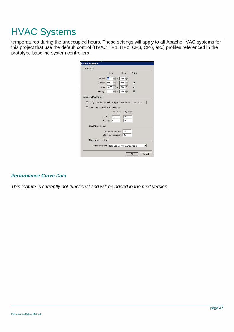
System Schedules
Set ApHVAC system operation schedules. Indicate the occupied and unoccupied hours and theassociated heating and cooling set points. The morning start-up and after-hours operation are inrelation to the occupied hours. Select the appropriate control strategy for operation using setback
HVAC Systems
page 42
Performance Rating Method
temperatures during the unoccupied hours. These settings will apply to all ApacheHVAC systems forthis project that use the default control (HVAC HP1, HP2, CP3, CP6, etc.) profiles referenced in theprototype baseline system controllers.
Performance Curve Data
This feature is currently not functional and will be added in the next version.

Other Input Data
page 43
Performance Rating Method
Other Input Data
Figure 40 - Other Input Data - Tasks
Renewable Energy Systems
There are three types of renewable systems available:
PVS Generator Wind Power CHP Generator

Other Input Data
page 44
Performance Rating Method
Utility Tariffs
This window allows you to set the fuel cost (fixed rate) for each fuel type in $/kWh (electricity),$/therm (nat. gas), or $/kbtuh (coal or oil).
Fossil Fuel Type
All miscellaneous fuel codes are assumed to be electricity except for:
Space Heating

Other Input Data
page 45
Performance Rating Method
Service Water Heating Cooking
These end-uses may be either electricity or fossil fuels, and there are two options for fuel codeassignment. If the fossil fuel option is chosen, this window allows you to change the fuel type forthese fuel codes for the sake of calculating fuel consumption and energy cost.

Generate Baseline
page 46
Performance Rating Method
Generate Baseline
Figure 41 - Generate Baseline Tasks
Generate the Baseline Model
This navigator step automatically generates the baseline models & assigns all relevant baselineinformation created in previous navigator steps/stages.

Generate Baseline
page 47
Performance Rating Method

Sizing Runs
page 48
Performance Rating Method
Sizing Runs
Figure 42 - Sizing Runs Sub-categories and Tasks
Room Load CalculationsThis navigator step automatically opens up the ApacheLoads dialog with default information applied.The user can edit the information relating to the proposed model. The four baseline runs aregenerated automatically.

Sizing Runs
page 49
Performance Rating Method
As with a normal ApacheLoads run this will generate information relating to room heating and coolingloads. This information is then used to populate the default PRM sizing sheets located in the ‘LoadsData’ folder of the project directory. This will generate flowrate data for use in the proposed andbaseline HVAC networks.
Assign Room Sizing DataThis step automatically assigns the sizing data generated from the step above to the proposed andbaseline HVAC networks.
System Load CalculationsThis navigator step opens up the ApacheLoads dialog again, this time an ApacheHVAC network isassigned in order to enable a system sizing calculation. This will provide information to size varioussystem elements i.e. fan and coil data.
As above, the user can edit the information relating to the proposed model. The four baseline runsare generated automatically.
Assign System Sizing DataThis step automatically assigns the sizing data generated from the step above to the proposed andbaseline HVAC networks.

Sizing Runs
page 50
Performance Rating Method
Sizing Reports
ProposedThis step enables the generation or display of a system level report for the proposed model. Thereport is broken down into three sections
Project Summary:
Contains information relating to the project area and volume, input data for the sizing calculations anddesign weather data.

Sizing Runs
page 51
Performance Rating Method
System Sizing Plant Loads:
Contains information relating to the overall performance of the heating and cooling systems e.g. thesystem type, the floor area served and peak load occurrence.
System Sizing System Loads:
Contains detailed information relating to performance of each individual system including sizing datarelating to each individual room served by the system. The information includes:

Sizing Runs
page 52
Performance Rating Method
Heating and cooling coil sizesSupply fan dataReturn fan dataExhaust fan data (optional)O.A dataLocal heating coil dataLocal airflow and fan data
Engineering checks are also provided.
Baseline 0°The report contains data relating to the Baseline 0o model sizing runs.
Baseline 90°The report contains data relating to the Baseline 90o model sizing runs.
Baseline 180°The report contains data relating to the Baseline 180o model sizing runs.
Baseline 270°The report contains data relating to the Baseline 270o model sizing runs.

Simulations
page 53
Performance Rating Method
Simulations
Figure 43 - Simulations Tasks
Proposed Model SimulationThis step allows the user to set up a full annual simulation for the proposed model.
0° Baseline Model SimulationThis step will automatically run a full annual simulation for the 0o baseline model.
Full PRM SimulationThis step will run a full annual simulation for the proposed and all four baseline models. The user isrequired to set up data relating to the proposed simulation. The four baseline simulations are runautomatically.

Results
page 54
Performance Rating Method
Results
Figure 44 - Results Navigator Sub-categories and Tasks
BPRM Report
BPRM results are presented in a format similar to the standard LEED letter template.
Initially user specified information is entered.
The Navigator then generates individual tables from within the report. Finally the BPRM report can begenerated in full.
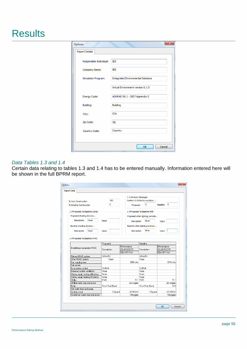
User DetailsInput user details for use in the full BPRM report.
Results
page 55
Performance Rating Method
Data Tables 1.3 and 1.4Certain data relating to tables 1.3 and 1.4 has to be entered manually. Information entered here willbe shown in the full BPRM report.
Results
page 56
Performance Rating Method
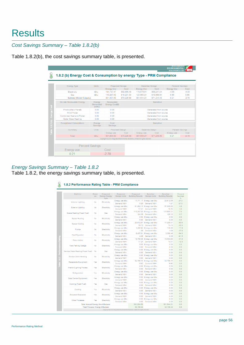
Cost Savings Summary – Table 1.8.2(b)
Table 1.8.2(b), the cost savings summary table, is presented.
Energy Savings Summary – Table 1.8.2Table 1.8.2, the energy savings summary table, is presented.

Results
page 57
Performance Rating Method
Baseline Costs – Table 1.8.1(b)Table 1.8.1(b), the baseline costs table, is presented.
Baseline Energy – Table 1.8.1Table 1.8.1, the baseline energy table, is presented.

Results
page 58
Performance Rating Method
Full ReportThe full BPRM report is generated containing all the above tables, plus
Table 1.1 - General Information

Results
page 59
Performance Rating Method
Table 1.2 – Space Summary
Table 1.3 – Advisory Messages
Table 1.4 – Comparison of Proposed versus Baseline Design

Results
page 60
Performance Rating Method
Table 1.5 – Energy Type Summary

Results
page 61
Performance Rating Method
Table 1.6 – On Site Renewable Energy
Table 1.7 - Exceptional Calculation Measures

Results
page 62
Performance Rating Method
10 Minute Checklist
ProposedThis step enables the generation or display of the 10 minute checklist report for the proposed model.The report contains four separate sections.
Building Utility Performance Table:
This table details the utility breakdown for each of the end use categories associated with the PRManalysis and includes electricity, fossil fuels and any renewables.
The report also displays the total energy associated with electricity and fossil fuels.

Results
page 63
Performance Rating Method
Building Energy Performance Table:
This table details an energy breakdown for each of the end use categories associated with the PRManalysis.
The report also displays the total site energy calculated.

Results
page 64
Performance Rating Method
Building Energy & End Use Summary Table - Electricity:
This table shows a detailed breakdown of the monthly performance of each of the PRM end usecategories for all electric meters.
The annual electricity energy is also shown for each end use and summed to give the total annualelectrical energy.
Note: The total column in this report may not be the sum of end uses; any excess generatedelectricity (negative total) is assumed to be exported

Results
page 65
Performance Rating Method
Building Energy & End Use Summary Table – Fossil Fuel:
This table shows a detailed breakdown of the monthly performance of each of the PRM end usecategories for all fossil fuel meters.
The annual fossil fuel energy consumption is also shown for each end use and summed to give thetotal annual fossil fuel energy consumption.
Baseline 0°This step enables the generation or display of the 10 minute checklist report for the baseline 0o
model.
Baseline 90°This step enables the generation or display of the 10 minute checklist report for the baseline 90o
model.
Baseline 180°This step enables the generation or display of the 10 minute checklist report for the baseline 180o
model.

Results
page 66
Performance Rating Method
Baseline 270°This step enables the generation or display of the 10 minute checklist report for the baseline 270o
model.
Display Selected ReportsThis step allows the selection of individual PRM runs (proposed plus four baseline), if multiplesimulation runs have been performed.