Embed Size (px)
Citation preview
© 2017
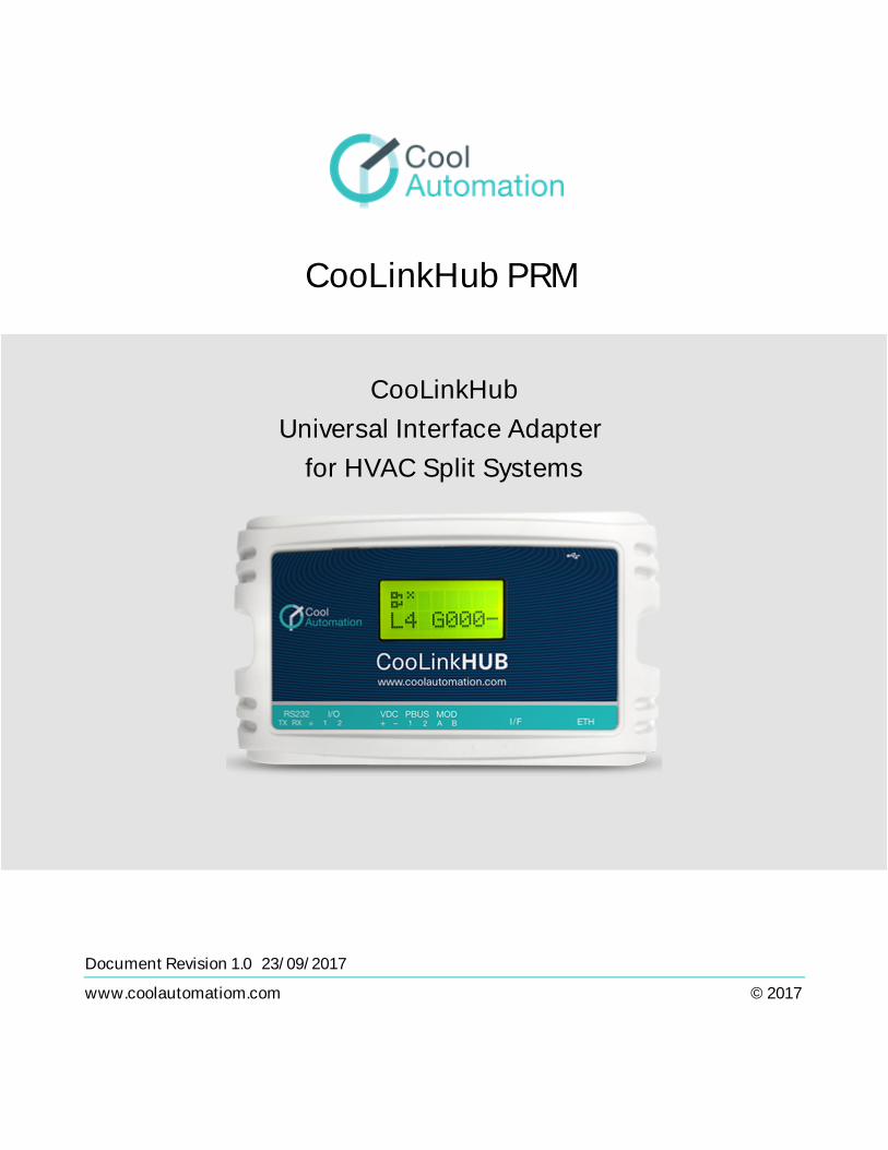
CooLinkHub PRM
CooLinkHubUniversal Interface Adapter
for HVAC Split Systems
Document Revision 1.0 23/09/2017
www.coolautomatiom.com
2www.coolautomation.com
CooLinkHub PRM 1.0
© 2017 CoolAutomation
Contents
Table of Contents
1 Revision History ................................................................................................................................. 4
2 ACRONYMS ........................................................................................................................................ 5
3 LAYOUT ............................................................................................................................................... 6
3.1 LCD Screen ................................................................................................................................................................................. 7
4 CONNECTIONS .................................................................................................................................. 8
4.1 Communication Lines .......................................................................................................................................................... 8PBUS .......................................................................................................................................................................................... 84.1.1
4.2 RS232 Port ................................................................................................................................................................................... 84.3 Ethernet ........................................................................................................................................................................................ 9
ASCII I/F IP Server ................................................................................................................................................................ 94.3.1CoolRemote Cloud Connection ......................................................................................................................................... 104.3.2
5 ASCII I/F ............................................................................................................................................ 11
5.1 General Definitions ............................................................................................................................................................. 11Messaging .............................................................................................................................................................................. 115.1.1Exit Code ................................................................................................................................................................................. 115.1.2UID ........................................................................................................................................................................................... 135.1.3
5.2 Configuration Commands ............................................................................................................................................... 14set ............................................................................................................................................................................................. 145.2.1ifconfig ..................................................................................................................................................................................... 165.2.2props ........................................................................................................................................................................................ 175.2.3
5.3 HVAC Status and Control Commands ...................................................................................................................... 18on .............................................................................................................................................................................................. 195.3.1allon .......................................................................................................................................................................................... 195.3.2off .............................................................................................................................................................................................. 195.3.3alloff ......................................................................................................................................................................................... 205.3.4cool ........................................................................................................................................................................................... 205.3.5heat .......................................................................................................................................................................................... 205.3.6fan ............................................................................................................................................................................................. 215.3.7dry ............................................................................................................................................................................................. 215.3.8auto .......................................................................................................................................................................................... 215.3.9haux .......................................................................................................................................................................................... 225.3.10temp ......................................................................................................................................................................................... 225.3.11feed .......................................................................................................................................................................................... 235.3.12fspeed ...................................................................................................................................................................................... 245.3.13swing ........................................................................................................................................................................................ 255.3.14filt .............................................................................................................................................................................................. 255.3.15
3www.coolautomation.com
CooLinkHub PRM 1.0
© 2017 CoolAutomation
Contents
ls ................................................................................................................................................................................................ 265.3.16ls2 ............................................................................................................................................................................................. 275.3.17query ........................................................................................................................................................................................ 285.3.18
4www.coolautomation.com
CooLinkHub PRM 1.0
© 2017 CoolAutomation
Revision History
1 Revision History
Revision Changes
1.0.0 Initial
5www.coolautomation.com
CooLinkHub PRM 1.0
© 2017 CoolAutomation
ACRONYMS
2 ACRONYMS
DC Digital Current
DTE Data Terminal Equipment
ETH Ethernet
GPIO General Purpose Input/Output
HVAC Heating Ventilation Air Conditioning
MAC Media Access Control
LCD Liquid Crystal Display
PRM Programmer's Reference Manual
6www.coolautomation.com
CooLinkHub PRM 1.0
© 2017 CoolAutomation
LAYOUT
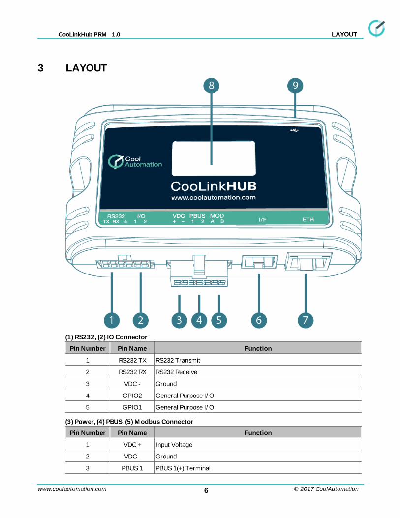
3 LAYOUT
(1) RS232, (2) IO Connector
Pin Number Pin Name Function
1 RS232 TX RS232 Transmit
2 RS232 RX RS232 Receive
3 VDC - Ground
4 GPIO2 General Purpose I/O
5 GPIO1 General Purpose I/O
(3) Power, (4) PBUS, (5) Modbus Connector
Pin Number Pin Name Function
1 VDC + Input Voltage
2 VDC - Ground
3 PBUS 1 PBUS 1(+) Terminal
7www.coolautomation.com
CooLinkHub PRM 1.0
© 2017 CoolAutomation
LAYOUT
4 PBUS 2 PBUS 2(-) Terminal
5 MOD A Modbus A(+) Terminal
6 MOD B Modbus B(-) Terminal
(6) Power Connector
Used to connect 12-24V DC power supply adapter.
(7) ETH Connector
RJ45 connector for ETH network.
(8) Mini USB Device Connector
Used to connect CooLinkHub to PC USB Host for configuration and firmware updates.
(9) LCD
Alphanumeric 8x2 characters LCD screen.
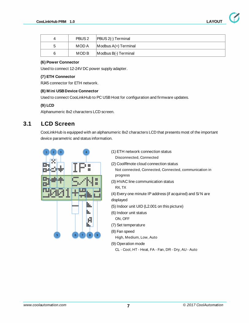
3.1 LCD Screen
CooLinkHub is equipped with an alphanumeric 8x2 characters LCD that presents most of the important
device parametric and status information.
(1) ETH network connection statusDisconnected, Connected
(2) CoolRmote cloud connection statusNot connected, Connected, Connected, communication inprogress
(3) HVAC line communication status RX, TX
(4) Every one minute IP address (if acquired) and S/N are
displayed
(5) Indoor unit UID (L2.001 on this picture)
(6) Indoor unit statusON, OFF
(7) Set temperature
(8) Fan speedHigh, Medium, Low, Auto
(9) Operation modeCL - Cool, HT - Heat, FA - Fan, DR - Dry, AU - Auto
8www.coolautomation.com
CooLinkHub PRM 1.0
© 2017 CoolAutomation
CONNECTIONS
4 CONNECTIONS
4.1 Communication Lines
CooLinkHub supports a number of communication lines intended for connection to PBUS interface as well
as integration with Home Automation and BMS control systems.
Line Type Acronym L1 L2 L3 L4 L5
HVAC
PBUS Master (PBM ) CH
Rolbit Zone Controller RLBT
Home Automation / BMS
KNX KNX
Modbus RTU CG5
HDL HDL
4.1.1 PBUS
PBUS is a CoolAutomation’s proprietary bus interface, based on shielded 2-wired cable (AWG24). It utilizes
free network topology.
PBUS is intended for connection of CoolPlug and ThermoPad devices to CooLinkHub. PBUS is a solution
for complete integration of (multi) split HVAC units with Home Automation and BMS systems.
4.2 RS232 Port
RS232 Interface in CooLinkHub is available from the RS232/IO connector. RS232 harness, provided with
CooLinkHub, routes RS232 signals to DB9 connector as shown below.
RS232/IO Pin DB9 Pin Signal Level Description
1 2 ±12V TxD Data from CooLinkHub
2 3 ±12V RxD Data to CooLinkHub
3 5 GND Ground
Maximal length of the RS232 Cable should not exceed 25m. The default CooLinkHub RS232 Port settings
are:
Baud Rate 9600
Data Bits 8
Parity Control None
Stop Bits 1
Flow Control None
By default RS232 Interface is dedicated for ASCII I/F protocol.
9www.coolautomation.com
CooLinkHub PRM 1.0
© 2017 CoolAutomation
CONNECTIONS
4.3 Ethernet
CooLinkHub incorporates an IEEE 802.3 compatible 10/100 Mb/s Ethernet port available via RJ45
connector. Ethernet port has a following features:
Parameter Value Notes
Max Ethernet Cable Length 137m CAT5 twisted pair cable
Supported Bit Rate 10/100 Mb/s
Supported Ethernet Protocols 10BASE-T/100BASE-TX
Protocol Auto-Negotiation Enabled Against Link Partner
RJ45 connector comprises Link and Activity indication LEDs used as specified below.
LED Color Function
Link Led Green ON for good link, OFF for no link
Activity Led Orange BLINKING for Tx/Rx Activity
Ethernet interface is used by a number of protocol modules available in CooLinkHub
· ASCII I/F (via ASCII I/F IP Server)
· Modbus IP (see Modbus Integration Guidlines document)
· HDL buspro IP
· SDDP
· CoolRemote
Network setting of the CooLinkHub are controlled with ifconfig command.
4.3.1 ASCII I/F IP Server
ASCII I/F IP Server referenced as Aserver is a classic row TCP/IP socket server. Aserver is started by
CooLinkHub once the Ethernet link is established and IP address is acquired. Aserver has following default
characteristics:
Maximal number of simultaneous connections 4
Default TCP/IP listening port 10102
Prompt character > enabled
Aserver can be configured with set command.
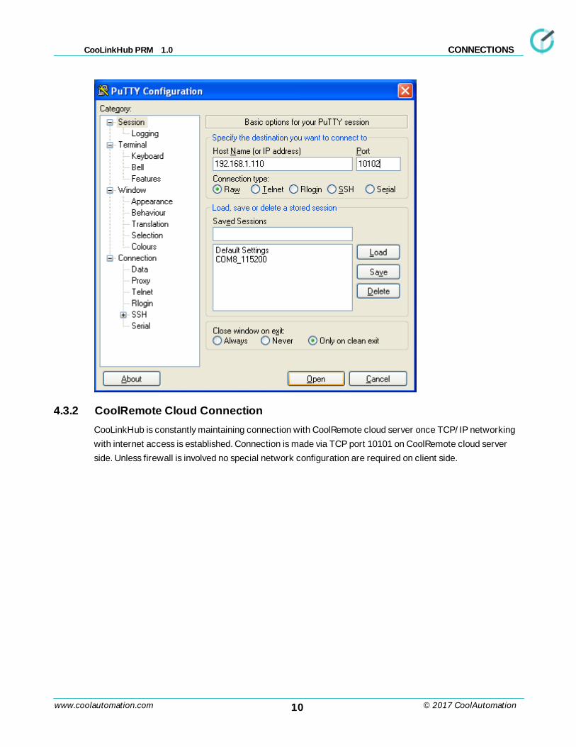
The screen shoot below illustrates the connection to Aserver with PuTTY utility (CooLinkHub IP address in
this example is 192.168.1.110).
10www.coolautomation.com
CooLinkHub PRM 1.0
© 2017 CoolAutomation
CONNECTIONS
4.3.2 CoolRemote Cloud Connection
CooLinkHub is constantly maintaining connection with CoolRemote cloud server once TCP/IP networking
with internet access is established. Connection is made via TCP port 10101 on CoolRemote cloud server
side. Unless firewall is involved no special network configuration are required on client side.
11www.coolautomation.com
CooLinkHub PRM 1.0
© 2017 CoolAutomation
ASCII I/F
5 ASCII I/F
ASCII I/F is a proprietary CoolAutomation's interface utilized by most of the CoolAutomation devices,
including CooLinkHub. In CooLinkHub ASCII I/F interface is running over RS232 connection and TCP/IP
network connection via Aserver.
5.1 General Definitions
5.1.1 Messaging
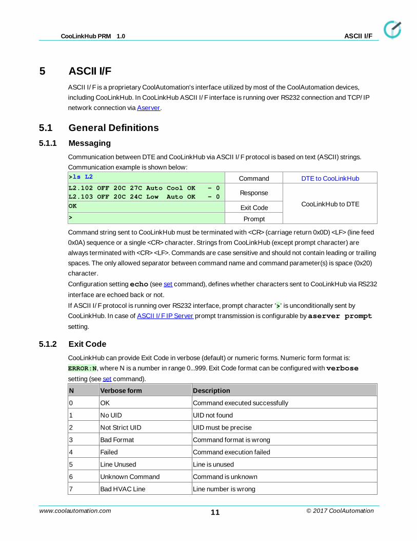
Communication between DTE and CooLinkHub via ASCII I/F protocol is based on text (ASCII) strings.
Communication example is shown below:>ls L2 Command DTE to CooLinkHubL2.102 OFF 20C 27C Auto Cool OK - 0
L2.103 OFF 20C 24C Low Auto OK - 0Response
CooLinkHub to DTEOK Exit Code> Prompt
Command string sent to CooLinkHub must be terminated with <CR> (carriage return 0x0D) <LF> (line feed
0x0A) sequence or a single <CR> character. Strings from CooLinkHub (except prompt character) are
always terminated with <CR> <LF>. Commands are case sensitive and should not contain leading or trailing
spaces. The only allowed separator between command name and command parameter(s) is space (0x20)
character.
Configuration setting echo (see set command), defines whether characters sent to CooLinkHub via RS232
interface are echoed back or not.
If ASCII I/F protocol is running over RS232 interface, prompt character '>' is unconditionally sent by
CooLinkHub. In case of ASCII I/F IP Server prompt transmission is configurable by aserver prompt
setting.
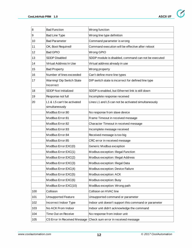
5.1.2 Exit Code
CooLinkHub can provide Exit Code in verbose (default) or numeric forms. Numeric form format is:
ERROR:N, where N is a number in range 0...999. Exit Code format can be configured with verbose
setting (see set command).
N Verbose form Description
0 OK Command executed successfully
1 No UID UID not found
2 Not Strict UID UID must be precise
3 Bad Format Command format is wrong
4 Failed Command execution failed
5 Line Unused Line is unused
6 Unknown Command Command is unknown
7 Bad HVAC Line Line number is wrong
12www.coolautomation.com
CooLinkHub PRM 1.0
© 2017 CoolAutomation
ASCII I/F
8 Bad Function Wrong function
9 Bad Line Type Wrong line type definition
10 Bad Parameter Command parameter is wrong
11 OK, Boot Required! Command execution will be effective after reboot
12 Bad GPIO Wrong GPIO
13 SDDP Disabled SDDP module is disabled, command can not be executed
14 Virtual Address In Use Virtual address already in use
15 Bad Property Wrong property
16 Number of lines exceeded Can't define more line types
17 Warning! Dip Switch State
Incorrect
DIP switch state is incorrect for defined line type
18 SDDP Not Initialized SDDP is enabled, but Ethernet link is still down
19 Response not full Incomplete response received
20 L1 & L5 can't be activated
simultaneously
Lines L1 and L5 can not be activated simultaneously
ModBus Error:80 No response from slave device
ModBus Error:81 Frame Timeout in received message
ModBus Error:82 Character Timeout in received message
ModBus Error:83 Incomplete message received
ModBus Error:84 Received message is too big
ModBus Error:85 CRC error in received message
ModBus Error:EXC(0) Generic Modbus exception
ModBus Error:EXC(1) Modbus exception: Illegal Function
ModBus Error:EXC(2) Modbus exception: Illegal Address
ModBus Error:EXC(3) Modbus exception: Illegal Data
ModBus Error:EXC(4) Modbus exception: Device Failure
ModBus Error:EXC(5) Modbus exception: ACK
ModBus Error:EXC(6) Modbus exception: Busy
ModBus Error:EXC(10) ModBus exception: Wrong path
100 Collision Collision on HVAC line
101 Unsupported Feature Unsupported command or parameter
102 Incorrect Indoor Type Indoor unit doesn't support this command or parameter
103 No ACK From Indoor Indoor unit didn't acknowledge the command
104 Time Out on Receive No response from indoor unit
105 CS Error In Received Message Check sum error in received message
13www.coolautomation.com
CooLinkHub PRM 1.0
© 2017 CoolAutomation
ASCII I/F
106 Line Init In Progress... Line initialization is in process
107 Line Error Error(s) on the HVAC line
108 Feed Disabled Indoor unit can't receive ambient temperature from
CooLinkHub
109 Line Queue Full Commands queue of the Line is full
150 HDL Not Initialized HDL line was not defined or Ethernet link is down
151 HDL DB Overflow HDL Data Base is full, can't add new configuration
152 HDL Eth Disabled HDL over Ethernet is disabled
200 UID Not Found Specified indoor unit not found in Data Base
201 Strict UID Not Found Specified indoor unit by not found in Data Base
202 Indoor Removed Indoor unit removed from Data Base
203 DB Overflow Indoor units Data Base is full
204 Group DB Overflow Group Data Base is full
205 VA DB Overflow Virtual address Data Base is full
206 FDB5 Overflow Properties Data Base is full
207 Incorrect Unit Class Wrong class of the HVAC unit
250 Link DB Overflow Link Data Base is full
251 No CoolLinkHub Line CoolLinkHub line is not defined
252 Auto Visibility Failed There was an error of visibility during link creation
253 Link already exists Device already linked
307 KNX DB Overflow KNX Data Base is full
309 KNX Not Connected No communication with KNX extender
310 KNX Line Not Started KNX line not defined
450 Luxom Disabled Luxom module not enabled
451 Luxom DB Overflow Luxom Data Base is full
452 Luxom Not Initialized Luxom module not initialized
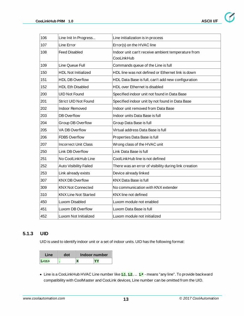
5.1.3 UID
UID is used to identify indoor unit or a set of indoor units. UID has the following format:
Line dot Indoor numberL<n> . X YY
· Line is a CooLinkHub HVAC Line number like L1, L2, ... L* - means "any line". To provide backward
compatibility with CoolMaster and CooLink devices, Line number can be omitted from the UID.
14www.coolautomation.com
CooLinkHub PRM 1.0
© 2017 CoolAutomation
ASCII I/F
· Dot is a separator between Line number and Indoor number. If Line number is omitted or has a L* form,
dot must also be omitted.
· Indoor number is an indoor unit number in HVAC system. Indoor number can be *, that means "any"
UID Examples:
L1.102 Indoor Unit 102 on line L1
L2.003 Indoor Unit 003 on line L2
L*100 Set of Indoor Units 100 on all lines
L3.1* Set of Indoor Units 1xx on line L3 (L3.100, L3.101, ... )
L4 All Indoors on line L4
L* All Indoors on all lines
203 Similar to L*203 (for backward compatibility only)
UID_STRICT
In some cases only specific indoor unit has to be referenced by UID. In this case it is required to use
UID_STRICT format: Ln.XYY, where * usage is prohibited and Line number can not be omitted.
5.2 Configuration Commands
5.2.1 set
SYNOPSISset [<SETTING> <VALUE>]set defaults
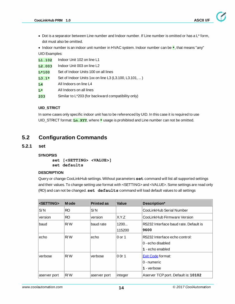
DESCRIPTION
Query or change CooLinkHub settings. Without parameters set command will list all supported settings
and their values. To change setting use format with <SETTING> and <VALUE>. Some settings are read only
(RO) and can not be changed. set defaults command will load default values to all settings
<SETTING> Mode Printed as Value Description*
S/N RO S/N CooLinkHub Serial Number
version RO version X.Y.Z CooLinkHub Firmware Version
baud R/W baud rate 1200...
115200
RS232 Interface baud rate. Default is
9600
echo R/W echo 0 or 1 RS232 Interface echo control:
0 - echo disabled
1 - echo enabled
verbose R/W verbose 0 0r 1 Exit Code format:
0 - numeric
1 - verbose
aserver port R/W aserver port integer Aserver TCP port. Default is: 10102
15www.coolautomation.com
CooLinkHub PRM 1.0
© 2017 CoolAutomation
ASCII I/F
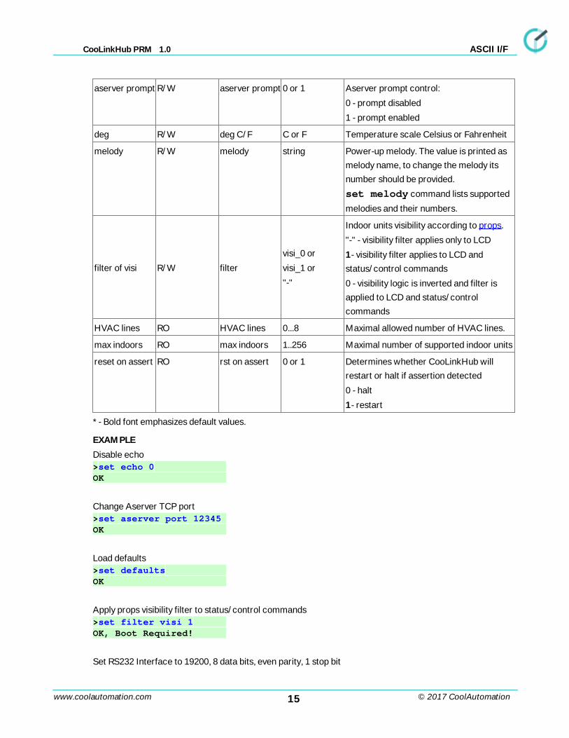
aserver prompt R/W aserver prompt 0 or 1 Aserver prompt control:
0 - prompt disabled
1 - prompt enabled
deg R/W deg C/F C or F Temperature scale Celsius or Fahrenheit
melody R/W melody string Power-up melody. The value is printed as
melody name, to change the melody its
number should be provided.
set melody command lists supported
melodies and their numbers.
filter of visi R/W filter
visi_0 or
visi_1 or
"-"
Indoor units visibility according to props.
"-" - visibility filter applies only to LCD
1- visibility filter applies to LCD and
status/control commands
0 - visibility logic is inverted and filter is
applied to LCD and status/control
commands
HVAC lines RO HVAC lines 0...8 Maximal allowed number of HVAC lines.
max indoors RO max indoors 1..256 Maximal number of supported indoor units
reset on assert RO rst on assert 0 or 1 Determines whether CooLinkHub will
restart or halt if assertion detected
0 - halt
1- restart
* - Bold font emphasizes default values.
EXAMPLE
Disable echo>set echo 0 OK
Change Aserver TCP port>set aserver port 12345 OK
Load defaults>set defaults OK
Apply props visibility filter to status/control commands>set filter visi 1 OK, Boot Required!
Set RS232 Interface to 19200, 8 data bits, even parity, 1 stop bit
16www.coolautomation.com
CooLinkHub PRM 1.0
© 2017 CoolAutomation
ASCII I/F
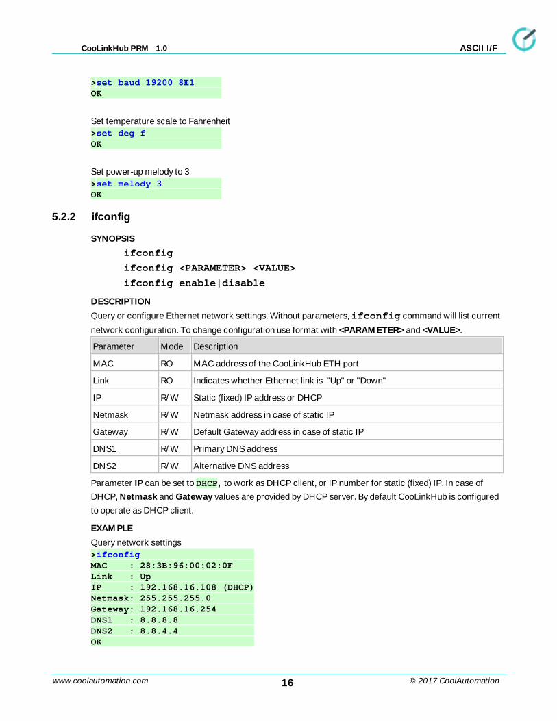
>set baud 19200 8E1 OK
Set temperature scale to Fahrenheit>set deg f OK
Set power-up melody to 3>set melody 3 OK
5.2.2 ifconfig
SYNOPSIS
ifconfig
ifconfig <PARAMETER> <VALUE>
ifconfig enable|disable
DESCRIPTION
Query or configure Ethernet network settings. Without parameters, ifconfig command will list current
network configuration. To change configuration use format with <PARAMETER> and <VALUE>.
Parameter Mode Description
MAC RO MAC address of the CooLinkHub ETH port
Link RO Indicates whether Ethernet link is "Up" or "Down"
IP R/W Static (fixed) IP address or DHCP
Netmask R/W Netmask address in case of static IP
Gateway R/W Default Gateway address in case of static IP
DNS1 R/W Primary DNS address
DNS2 R/W Alternative DNS address
Parameter IP can be set to DHCP, to work as DHCP client, or IP number for static (fixed) IP. In case of
DHCP, Netmask and Gateway values are provided by DHCP server. By default CooLinkHub is configured
to operate as DHCP client.
EXAMPLE
Query network settings>ifconfig MAC : 28:3B:96:00:02:0F Link : Up IP : 192.168.16.108 (DHCP)Netmask: 255.255.255.0 Gateway: 192.168.16.254 DNS1 : 8.8.8.8 DNS2 : 8.8.4.4 OK
17www.coolautomation.com
CooLinkHub PRM 1.0
© 2017 CoolAutomation
ASCII I/F
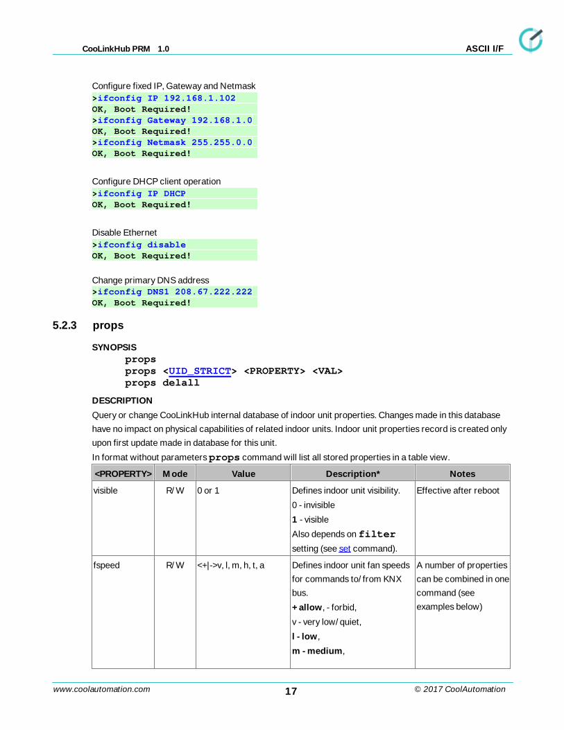
Configure fixed IP, Gateway and Netmask>ifconfig IP 192.168.1.102 OK, Boot Required! >ifconfig Gateway 192.168.1.0 OK, Boot Required! >ifconfig Netmask 255.255.0.0 OK, Boot Required!
Configure DHCP client operation>ifconfig IP DHCP OK, Boot Required!
Disable Ethernet >ifconfig disable OK, Boot Required!
Change primary DNS address>ifconfig DNS1 208.67.222.222 OK, Boot Required!
5.2.3 props
SYNOPSISpropsprops <UID_STRICT> <PROPERTY> <VAL>props delall
DESCRIPTION
Query or change CooLinkHub internal database of indoor unit properties. Changes made in this database
have no impact on physical capabilities of related indoor units. Indoor unit properties record is created only
upon first update made in database for this unit.
In format without parameters props command will list all stored properties in a table view.
<PROPERTY> Mode Value Description* Notes
visible R/W 0 or 1 Defines indoor unit visibility.
0 - invisible
1 - visible
Also depends on filter
setting (see set command).
Effective after reboot
fspeed R/W <+|->v, l, m, h, t, a Defines indoor unit fan speeds
for commands to/from KNX
bus.
+ allow, - forbid,
v - very low/quiet,
l - low,
m - medium,
A number of properties
can be combined in one
command (see
examples below)
18www.coolautomation.com
CooLinkHub PRM 1.0
© 2017 CoolAutomation
ASCII I/F
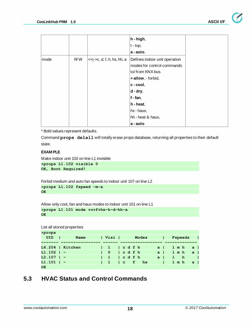
h - high,
t - top,
a - auto.
mode R/W <+|->c, d, f, h, hx, hh, a Defines indoor unit operation
modes for control commands
to/from KNX bus.
+ allow, - forbid,
c - cool,
d - dry,
f - fan,
h - heat,
hx - haux,
hh - heat & haux,
a - auto
* Bold values represent defaults.
Command props delall will totally erase props database, returning all properties to their default
state.
EXAMPLE
Make indoor unit 102 on line L1 invisible>props L1.102 visible 0 OK, Boot Required!
Forbid medium and auto fan speeds to indoor unit 107 on line L2>props L1.102 fspeed -m-a OK
Allow only cool, fan and haux modes to indoor unit 101 on line L1>props L1.101 mode +c+f+hx-h-d-hh-a OK
List all stored properties>props UID | Name | Visi | Modes | Fspeeds |------- ---------------- ------ ----------------- ------------- L6.204 | Kitchen | 1 | c d f h a | l m h a |L1.102 | - | 0 | c d f h a | l m h a |L2.107 | - | 1 | c d f h a | l h |L1.101 | - | 1 | c f hx | l m h a |OK
5.3 HVAC Status and Control Commands
19www.coolautomation.com
CooLinkHub PRM 1.0
© 2017 CoolAutomation
ASCII I/F
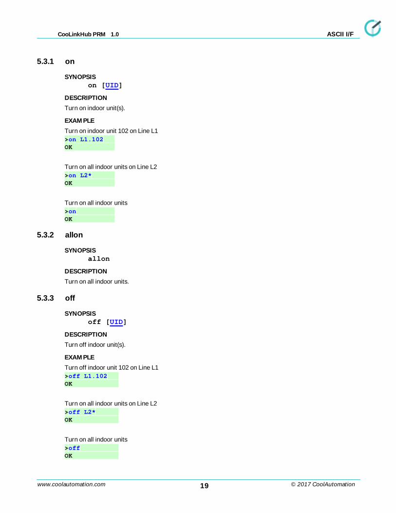
5.3.1 on
SYNOPSISon [UID]
DESCRIPTION
Turn on indoor unit(s).
EXAMPLE
Turn on indoor unit 102 on Line L1>on L1.102 OK
Turn on all indoor units on Line L2 >on L2* OK
Turn on all indoor units>on OK
5.3.2 allon
SYNOPSISallon
DESCRIPTION
Turn on all indoor units.
5.3.3 off
SYNOPSISoff [UID]
DESCRIPTION
Turn off indoor unit(s).
EXAMPLE
Turn off indoor unit 102 on Line L1>off L1.102 OK
Turn on all indoor units on Line L2 >off L2* OK
Turn on all indoor units>off OK
20www.coolautomation.com
CooLinkHub PRM 1.0
© 2017 CoolAutomation
ASCII I/F
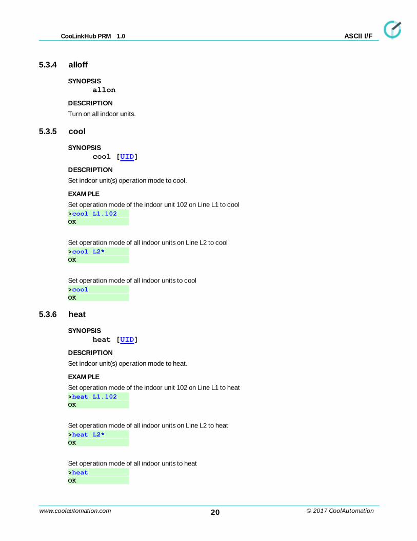
5.3.4 alloff
SYNOPSISallon
DESCRIPTION
Turn on all indoor units.
5.3.5 cool
SYNOPSIScool [UID]
DESCRIPTION
Set indoor unit(s) operation mode to cool.
EXAMPLE
Set operation mode of the indoor unit 102 on Line L1 to cool>cool L1.102 OK
Set operation mode of all indoor units on Line L2 to cool >cool L2* OK
Set operation mode of all indoor units to cool >cool OK
5.3.6 heat
SYNOPSISheat [UID]
DESCRIPTION
Set indoor unit(s) operation mode to heat.
EXAMPLE
Set operation mode of the indoor unit 102 on Line L1 to heat>heat L1.102 OK
Set operation mode of all indoor units on Line L2 to heat >heat L2* OK
Set operation mode of all indoor units to heat >heat OK
21www.coolautomation.com
CooLinkHub PRM 1.0
© 2017 CoolAutomation
ASCII I/F
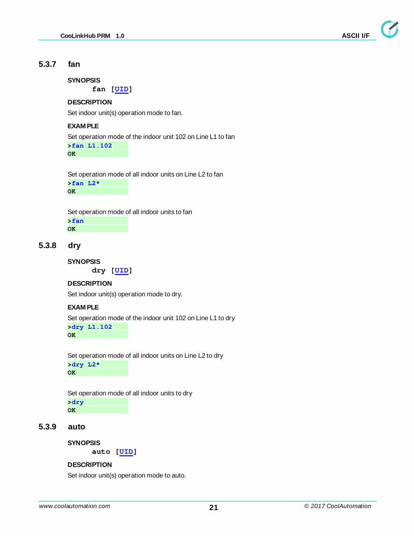
5.3.7 fan
SYNOPSISfan [UID]
DESCRIPTION
Set indoor unit(s) operation mode to fan.
EXAMPLE
Set operation mode of the indoor unit 102 on Line L1 to fan>fan L1.102 OK
Set operation mode of all indoor units on Line L2 to fan >fan L2* OK
Set operation mode of all indoor units to fan >fan OK
5.3.8 dry
SYNOPSISdry [UID]
DESCRIPTION
Set indoor unit(s) operation mode to dry.
EXAMPLE
Set operation mode of the indoor unit 102 on Line L1 to dry>dry L1.102 OK
Set operation mode of all indoor units on Line L2 to dry >dry L2* OK
Set operation mode of all indoor units to dry >dry OK
5.3.9 auto
SYNOPSISauto [UID]
DESCRIPTION
Set indoor unit(s) operation mode to auto.
22www.coolautomation.com
CooLinkHub PRM 1.0
© 2017 CoolAutomation
ASCII I/F
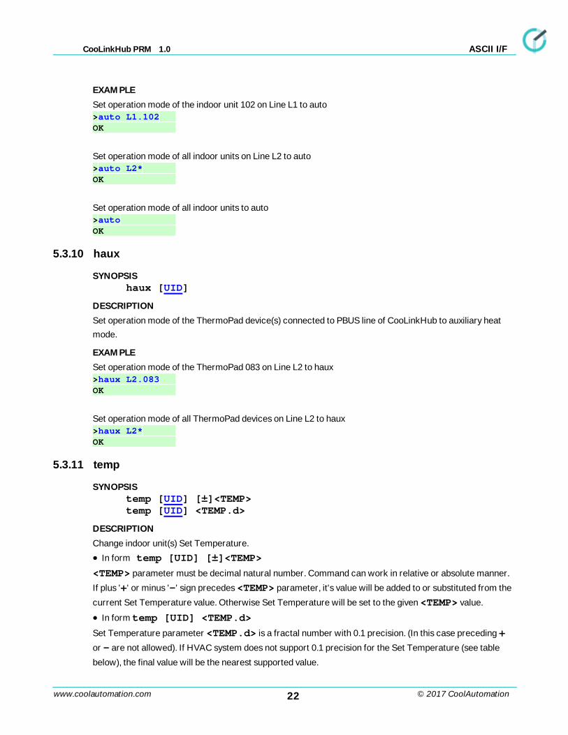
EXAMPLE
Set operation mode of the indoor unit 102 on Line L1 to auto>auto L1.102 OK
Set operation mode of all indoor units on Line L2 to auto >auto L2* OK
Set operation mode of all indoor units to auto >auto OK
5.3.10 haux
SYNOPSIShaux [UID]
DESCRIPTION
Set operation mode of the ThermoPad device(s) connected to PBUS line of CooLinkHub to auxiliary heat
mode.
EXAMPLE
Set operation mode of the ThermoPad 083 on Line L2 to haux>haux L2.083 OK
Set operation mode of all ThermoPad devices on Line L2 to haux >haux L2* OK
5.3.11 temp
SYNOPSIStemp [UID] [±]<TEMP>temp [UID] <TEMP.d>
DESCRIPTION
Change indoor unit(s) Set Temperature.
· In form temp [UID] [±]<TEMP>
<TEMP> parameter must be decimal natural number. Command can work in relative or absolute manner.
If plus '+' or minus '-' sign precedes <TEMP> parameter, it's value will be added to or substituted from the
current Set Temperature value. Otherwise Set Temperature will be set to the given <TEMP> value.
· In form temp [UID] <TEMP.d>
Set Temperature parameter <TEMP.d> is a fractal number with 0.1 precision. (In this case preceding +
or - are not allowed). If HVAC system does not support 0.1 precision for the Set Temperature (see table
below), the final value will be the nearest supported value.
23www.coolautomation.com
CooLinkHub PRM 1.0
© 2017 CoolAutomation
ASCII I/F
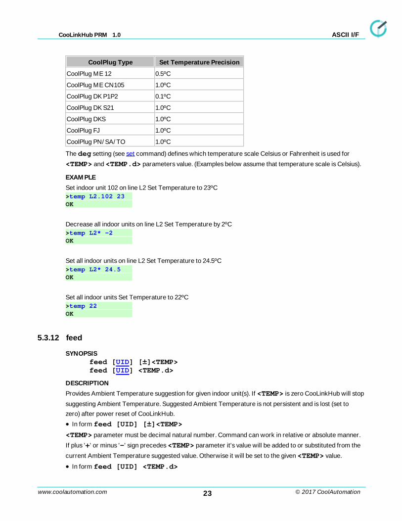
CoolPlug Type Set Temperature Precision
CoolPlug ME 12 0.5ºC
CoolPlug ME CN105 1.0ºC
CoolPlug DK P1P2 0.1ºC
CoolPlug DK S21 1.0ºC
CoolPlug DKS 1.0ºC
CoolPlug FJ 1.0ºC
CoolPlug PN/SA/TO 1.0ºC
The deg setting (see set command) defines which temperature scale Celsius or Fahrenheit is used for
<TEMP> and <TEMP.d> parameters value. (Examples below assume that temperature scale is Celsius).
EXAMPLE
Set indoor unit 102 on line L2 Set Temperature to 23ºC>temp L2.102 23 OK
Decrease all indoor units on line L2 Set Temperature by 2ºC>temp L2* -2 OK
Set all indoor units on line L2 Set Temperature to 24.5ºC>temp L2* 24.5 OK
Set all indoor units Set Temperature to 22ºC>temp 22 OK
5.3.12 feed
SYNOPSISfeed [UID] [±]<TEMP>feed [UID] <TEMP.d>
DESCRIPTION
Provides Ambient Temperature suggestion for given indoor unit(s). If <TEMP> is zero CooLinkHub will stop
suggesting Ambient Temperature. Suggested Ambient Temperature is not persistent and is lost (set to
zero) after power reset of CooLinkHub.
· In form feed [UID] [±]<TEMP>
<TEMP> parameter must be decimal natural number. Command can work in relative or absolute manner.
If plus '+' or minus '-' sign precedes <TEMP> parameter it's value will be added to or substituted from the
current Ambient Temperature suggested value. Otherwise it will be set to the given <TEMP> value.
· In form feed [UID] <TEMP.d>
24www.coolautomation.com
CooLinkHub PRM 1.0
© 2017 CoolAutomation
ASCII I/F
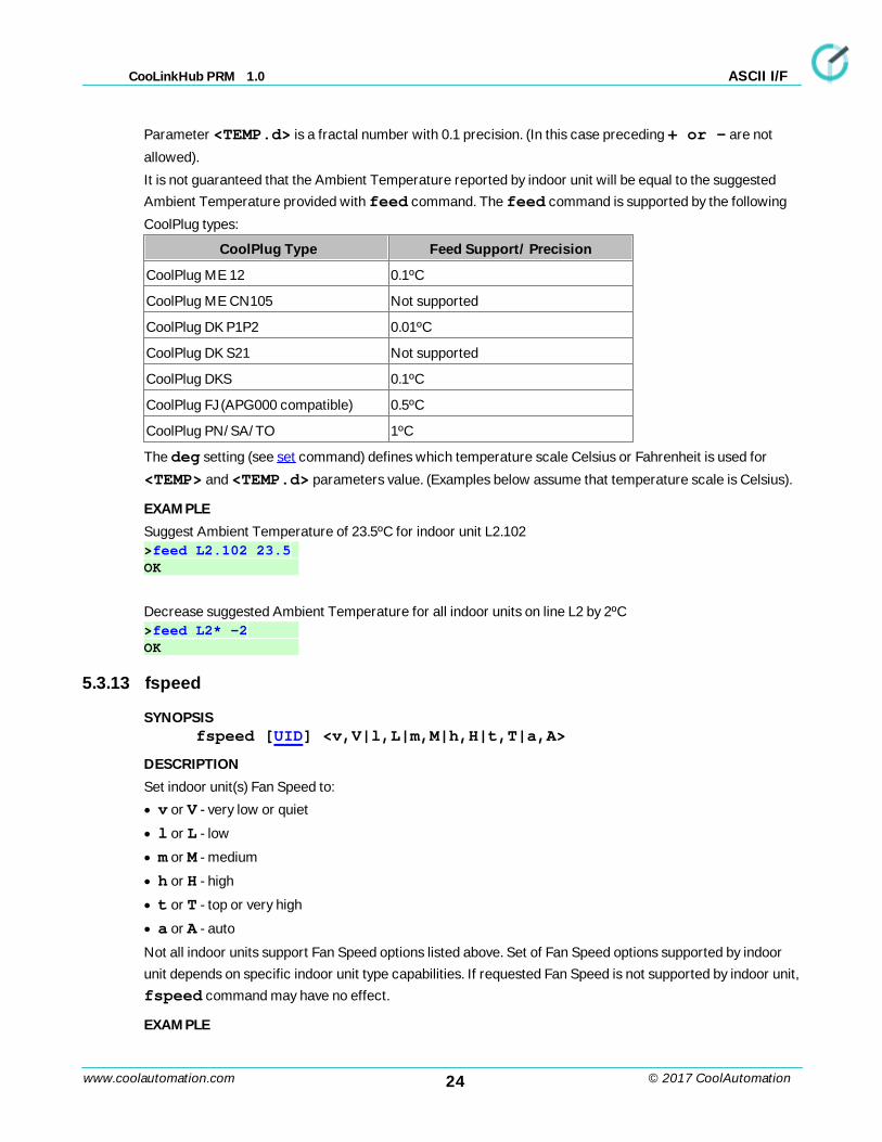
Parameter <TEMP.d> is a fractal number with 0.1 precision. (In this case preceding + or - are not
allowed).
It is not guaranteed that the Ambient Temperature reported by indoor unit will be equal to the suggested
Ambient Temperature provided with feed command. The feed command is supported by the following
CoolPlug types:
CoolPlug Type Feed Support/ Precision
CoolPlug ME 12 0.1ºC
CoolPlug ME CN105 Not supported
CoolPlug DK P1P2 0.01ºC
CoolPlug DK S21 Not supported
CoolPlug DKS 0.1ºC
CoolPlug FJ (APG000 compatible) 0.5ºC
CoolPlug PN/SA/TO 1ºC
The deg setting (see set command) defines which temperature scale Celsius or Fahrenheit is used for
<TEMP> and <TEMP.d> parameters value. (Examples below assume that temperature scale is Celsius).
EXAMPLE
Suggest Ambient Temperature of 23.5ºC for indoor unit L2.102>feed L2.102 23.5 OK
Decrease suggested Ambient Temperature for all indoor units on line L2 by 2ºC>feed L2* -2 OK
5.3.13 fspeed
SYNOPSISfspeed [UID] <v,V|l,L|m,M|h,H|t,T|a,A>
DESCRIPTION
Set indoor unit(s) Fan Speed to:
· v or V - very low or quiet
· l or L - low
· m or M - medium
· h or H - high
· t or T - top or very high
· a or A - auto
Not all indoor units support Fan Speed options listed above. Set of Fan Speed options supported by indoor
unit depends on specific indoor unit type capabilities. If requested Fan Speed is not supported by indoor unit,
fspeed command may have no effect.
EXAMPLE
25www.coolautomation.com
CooLinkHub PRM 1.0
© 2017 CoolAutomation
ASCII I/F
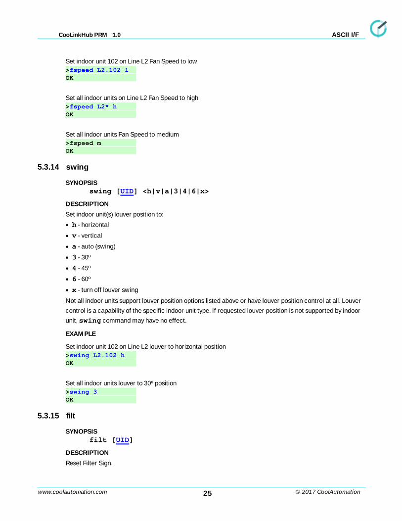
Set indoor unit 102 on Line L2 Fan Speed to low>fspeed L2.102 l OK
Set all indoor units on Line L2 Fan Speed to high>fspeed L2* h OK
Set all indoor units Fan Speed to medium>fspeed m OK
5.3.14 swing
SYNOPSISswing [UID] <h|v|a|3|4|6|x>
DESCRIPTION
Set indoor unit(s) louver position to:
· h - horizontal
· v - vertical
· a - auto (swing)
· 3 - 30º
· 4 - 45º
· 6 - 60º
· x - turn off louver swing
Not all indoor units support louver position options listed above or have louver position control at all. Louver
control is a capability of the specific indoor unit type. If requested louver position is not supported by indoor
unit, swing command may have no effect.
EXAMPLE
Set indoor unit 102 on Line L2 louver to horizontal position>swing L2.102 h OK
Set all indoor units louver to 30º position>swing 3 OK
5.3.15 filt
SYNOPSISfilt [UID]
DESCRIPTION
Reset Filter Sign.
26www.coolautomation.com
CooLinkHub PRM 1.0
© 2017 CoolAutomation
ASCII I/F
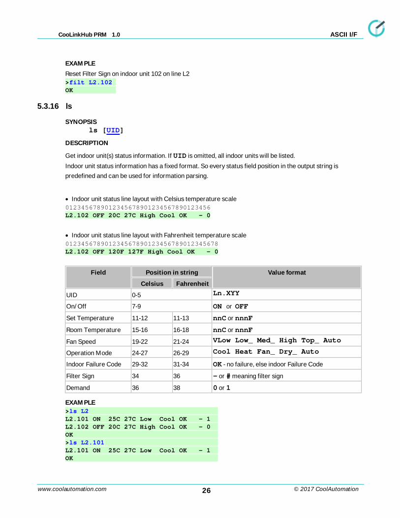
EXAMPLE
Reset Filter Sign on indoor unit 102 on line L2>filt L2.102 OK
5.3.16 ls
SYNOPSISls [UID]
DESCRIPTION
Get indoor unit(s) status information. If UID is omitted, all indoor units will be listed.
Indoor unit status information has a fixed format. So every status field position in the output string is
predefined and can be used for information parsing.
· Indoor unit status line layout with Celsius temperature scale0123456789012345678901234567890123456L2.102 OFF 20C 27C High Cool OK - 0
· Indoor unit status line layout with Fahrenheit temperature scale012345678901234567890123456789012345678L2.102 OFF 120F 127F High Cool OK - 0
Field Position in string Value format
Celsius Fahrenheit
UID 0-5 Ln.XYY
On/Off 7-9 ON or OFF
Set Temperature 11-12 11-13 nnC or nnnF
Room Temperature 15-16 16-18 nnC or nnnF
Fan Speed 19-22 21-24 VLow Low_ Med_ High Top_ Auto
Operation Mode 24-27 26-29 Cool Heat Fan_ Dry_ Auto
Indoor Failure Code 29-32 31-34 OK - no failure, else indoor Failure Code
Filter Sign 34 36 - or # meaning filter sign
Demand 36 38 0 or 1
EXAMPLE>ls L2 L2.101 ON 25C 27C Low Cool OK - 1 L2.102 OFF 20C 27C High Cool OK - 0 OK >ls L2.101 L2.101 ON 25C 27C Low Cool OK - 1 OK
27www.coolautomation.com
CooLinkHub PRM 1.0
© 2017 CoolAutomation
ASCII I/F
>ls L1.101 ON 25C 24C Low Cool OK - 1 L1.102 ON 22C 23C Med Cool OK - 0 L2.101 ON 25C 27C Low Cool OK - 1 L2.102 OFF 20C 27C High Cool OK - 0 OK
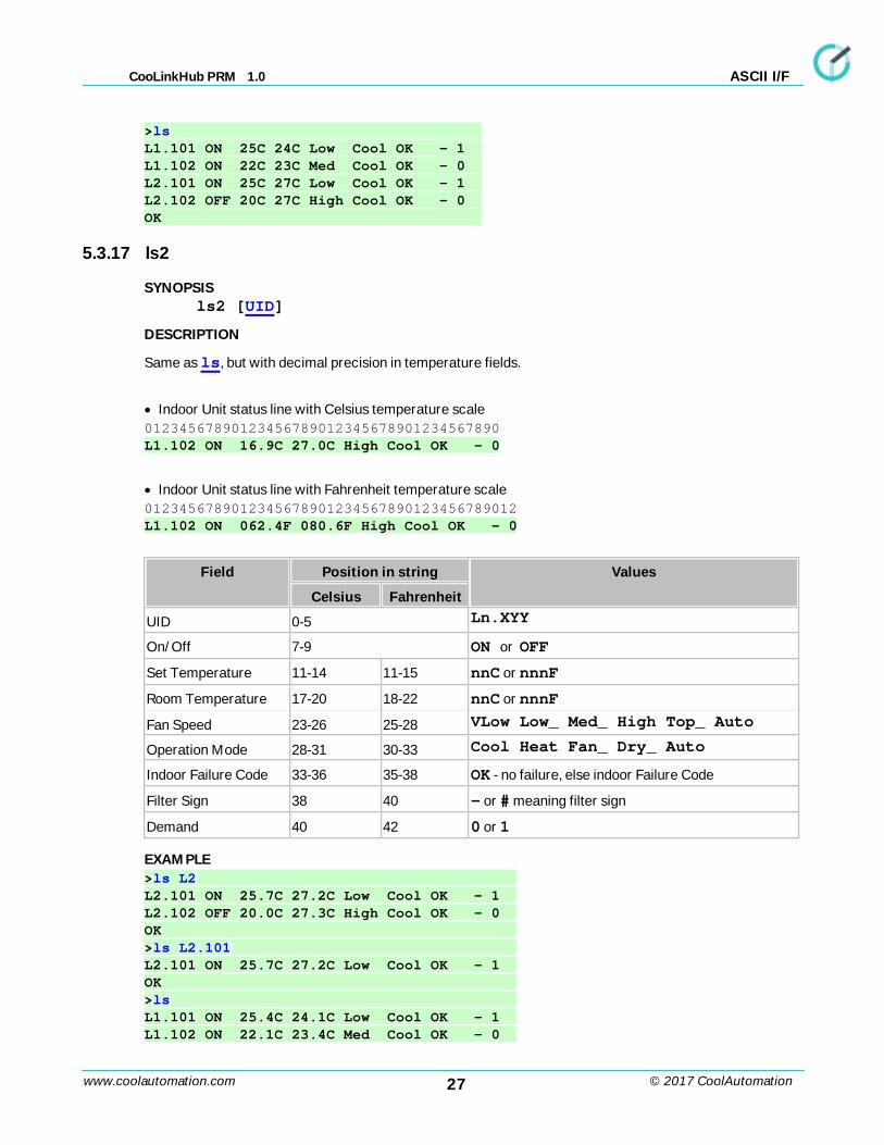
5.3.17 ls2
SYNOPSISls2 [UID]
DESCRIPTION
Same as ls, but with decimal precision in temperature fields.
· Indoor Unit status line with Celsius temperature scale01234567890123456789012345678901234567890L1.102 ON 16.9C 27.0C High Cool OK - 0
· Indoor Unit status line with Fahrenheit temperature scale0123456789012345678901234567890123456789012L1.102 ON 062.4F 080.6F High Cool OK - 0
Field Position in string Values
Celsius Fahrenheit
UID 0-5 Ln.XYY
On/Off 7-9 ON or OFF
Set Temperature 11-14 11-15 nnC or nnnF
Room Temperature 17-20 18-22 nnC or nnnF
Fan Speed 23-26 25-28 VLow Low_ Med_ High Top_ Auto
Operation Mode 28-31 30-33 Cool Heat Fan_ Dry_ Auto
Indoor Failure Code 33-36 35-38 OK - no failure, else indoor Failure Code
Filter Sign 38 40 - or # meaning filter sign
Demand 40 42 0 or 1
EXAMPLE>ls L2 L2.101 ON 25.7C 27.2C Low Cool OK - 1 L2.102 OFF 20.0C 27.3C High Cool OK - 0 OK >ls L2.101 L2.101 ON 25.7C 27.2C Low Cool OK - 1 OK >ls L1.101 ON 25.4C 24.1C Low Cool OK - 1 L1.102 ON 22.1C 23.4C Med Cool OK - 0
28www.coolautomation.com
CooLinkHub PRM 1.0
© 2017 CoolAutomation
ASCII I/F
L2.101 ON 25.7C 27.2C Low Cool OK - 1 L2.102 OFF 20.0C 27.3C High Cool OK - 0 OK
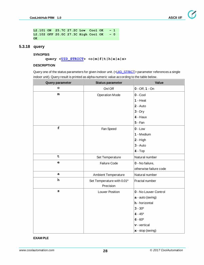
5.3.18 query
SYNOPSISquery <UID_STRICT> <o|m|f|t|h|e|a|s>
DESCRIPTION
Query one of the status parameters for given indoor unit. (<UID_STRICT> parameter references a single
indoor unit). Query result is printed as alpha-numeric value according to the table below.
Query parameter Status parameter Valueo On/Off 0 - Off, 1 - On
m Operation Mode 0 - Cool
1 - Heat
2 - Auto
3 - Dry
4 - Haux
5 - Fan
f Fan Speed 0 - Low
1 - Medium
2 - High
3 - Auto
4 - Top
t Set Temperature Natural number
e Failure Code 0 - No failure,
otherwise failure code
a Ambient Temperature Natural number
h Set Temperature with 0.01º
Precision
Fractal number
s Louver Position 0 - No Louver Control
a - auto (swing)
h - horizontal
3 - 30º
4 - 45º
6 - 60º
v - vertical
x - stop (swing)
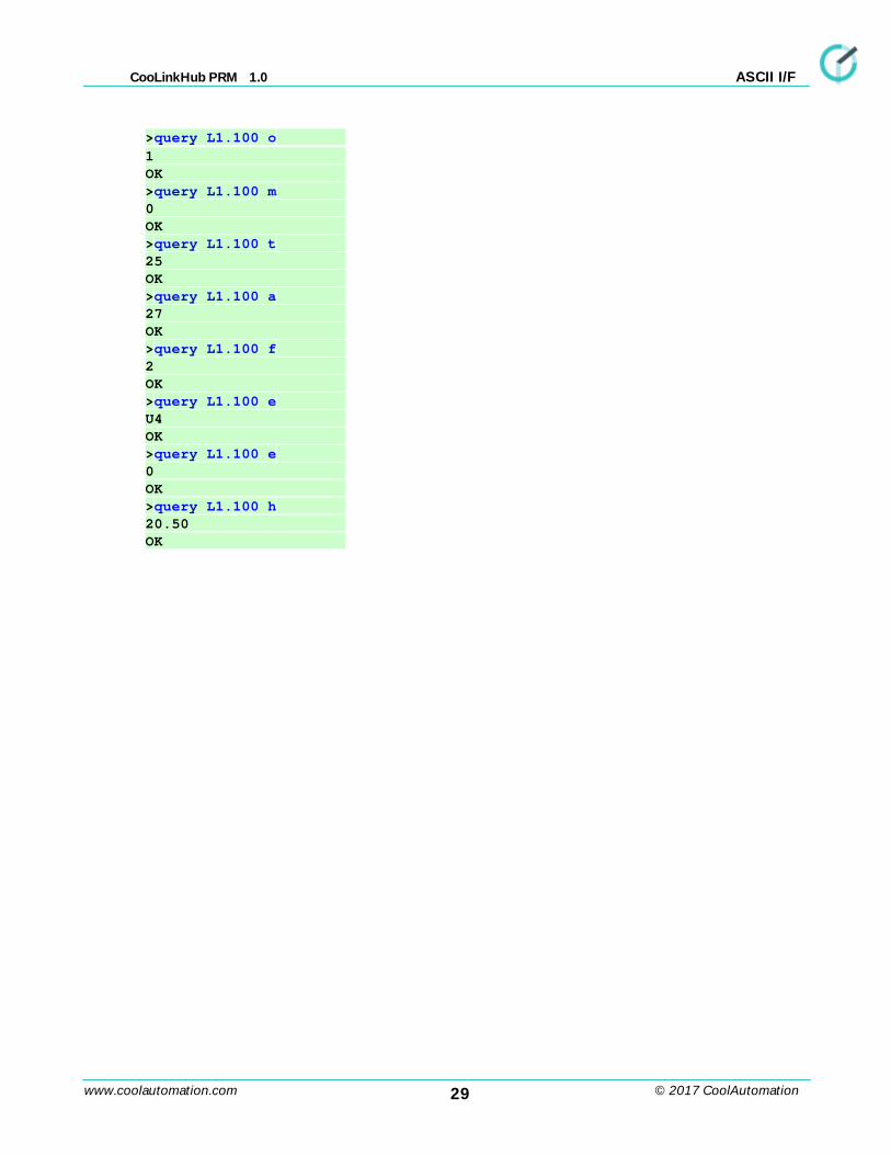
EXAMPLE
29www.coolautomation.com
CooLinkHub PRM 1.0
© 2017 CoolAutomation
ASCII I/F
>query L1.100 o
1 OK >query L1.100 m 0 OK >query L1.100 t 25 OK >query L1.100 a 27 OK >query L1.100 f 2 OK >query L1.100 e U4 OK >query L1.100 e 0 OK >query L1.100 h 20.50 OK