Embed Size (px)
Citation preview

A Summary of Vehicle Detection andSurveillance Technologies used inIntelligent Transportation Systems
Funded by the Federal Highway Administration’s IntelligentTransportation Systems Joint Program Office
Produced byThe Vehicle Detector Clearinghouse
A multi-state, pooled-fund project managed by theSouthwest Technology Development Institute (SWTDI) at
New Mexico State University (NMSU),and sponsored in cooperation with the U.S. Department of
Transportation FHWA
Fall 2000

SUMMARY OF VEHICLE DETECTION AND SURVEILLANCE TECHNOLOGIES USED
IN INTELLIGENT TRANSPORTATION SYSTEMS
SUBMITTED TO:
Federal Highway Administration s (FHWA) Intelligent Transportation Systems Joint
Program Office
PREPARED BY:
Luz Elena Y. MimbelaProject Manager
The Vehicle Detector ClearinghouseNew Mexico State University
P.O. Box 30001Las Cruces, NM 88003-8001
And
Lawrence A. Klein, Ph.D., P.E.Private Consultant314 Purdy Avenue
Placentia, CA 92870
With Assistance From:
Perry Kent, VDC Project ConsultantJohn L. Hamrick, VDC Project Consultant
Karen M. Luces, NMSUSylvia Herrera, NMSU
November 30, 2000
(Latest version of this handbook can be found at http://www.nmsu.edu/~traffic/)


ii
Disclaimer Notice
This document is disseminated under the sponsorship of the Department of Transportation in
the interest of information exchange. The United States Government assumes no liability for its
contents or use thereof.
The contents of this summary document reflect the views of the contractor and subcontractors,
who are responsible for the accuracy of the data presented herein. The contents do not
necessarily reflect the official policy of the Department of Transportation.
This document does not constitute a standard, specification, or regulation.
The United States Government or the Vehicle Detector Clearinghouse does not endorse products
or manufacturers. Vendor and manufacturer s names appear herein only because they are
considered essential to the purpose of this document.

iii
TABLE OF CONTENTS
CHAPTER 1 - INTRODUCTION . . . . . . . . . . . . . . . . . . . . . . . . . . . . . . . . . . . . . . . . . . . . . . . . . . . . . . . . . . . . . . . . . . . . . . . . 1 - 1
CHAPTER 2 - METHODS AND APPROACH . . . . . . . . . . . . . . . . . . . . . . . . . . . . . . . . . . . . . . . . . . . . . . . . . . . . . . . . . . 2 - 1
COLLECTION OF PRODUCT INFORMATION............................................................................................ 2-1COLLECTION OF USER INFORMATION.................................................................................................. 2-2COMPILATION OF INFORMATION........................................................................................................ 2-2
CHAPTER 3 – OVERVIEW OF VEHICLE DETECTION AND SURVEILLANCETECHNOLOGIES. . . . . . . . . . . . . . . . . . . . . . . . . . . . . . . . . . . . . . . . . . . . . . . . . . . . . . . . . . . . . . . . . . . . . . . . . . . . . . . . . . . . . . . . . . . 3 - 1
INTRUSIVE SENSORS ........................................................................................................................ 3-1NON-INTRUSIVE SENSORS ................................................................................................................ 3-2APPLICATIONS OF SENSOR COMBINATIONS.......................................................................................... 3-2RELATIVE COST OF SENSORS............................................................................................................ 3-3SENSOR TECHNOLOGY COMPARISON.................................................................................................. 3-4SUMMARY .................................................................................................................................... 3-9
CHAPTER 4 – INTRUSIVE TECHNOLOGIES . . . . . . . . . . . . . . . . . . . . . . . . . . . . . . . . . . . . . . . . . . . . . . . . . . . . . . . 4 - 1
PNEUMATIC ROAD TUBE ................................................................................................................. 4-1Principles of Operation................................................................................................................ 4-1Applications and Uses................................................................................................................. 4-1Advantages................................................................................................................................ 4-1Disadvantages............................................................................................................................ 4-2Installation Configuration............................................................................................................ 4-2
INDUCTIVE LOOP DETECTORS ........................................................................................................... 4-4Principles of Operation................................................................................................................ 4-4Applications and Uses................................................................................................................. 4-4Advantages................................................................................................................................ 4-5Disadvantages............................................................................................................................ 4-5
PIEZOELECTRIC SENSORS................................................................................................................. 4-7Principles of Operation................................................................................................................ 4-7Applications and Uses................................................................................................................. 4-8Bonding Materials…………………………………………………………………………………………….4-10Advantages...............................................................................................................................4-10Disadvantages...........................................................................................................................4-11
MAGNETIC SENSORS......................................................................................................................4-12Principles of Operation...............................................................................................................4-12Application and Uses .................................................................................................................4-12Advantages...............................................................................................................................4-13Disadvantages...........................................................................................................................4-13
WEIGH-IN-MOTION (WIM)..............................................................................................................4-17Application and Uses .................................................................................................................4-17Bending Plate ...........................................................................................................................4-22Piezoelectric .............................................................................................................................4-26Load Cell.................................................................................................................................4-29Capacitance Mat........................................................................................................................4-30Weigh-in-Motion System Costs...................................................................................................4-31
CHAPTER 5 – NON-INTRUSIVE TECHNOLOGIES . . . . . . . . . . . . . . . . . . . . . . . . . . . . . . . . . . . . . . . . . . . . . . . . 5 - 1
VIDEO IMAGE PROCESSOR................................................................................................................ 5-1

i v
Principles of Operation................................................................................................................ 5-1Application and Uses .................................................................................................................. 5-5Mounting and Traffic Viewing Considerations ................................................................................. 5-5Advantages................................................................................................................................ 5-6Disadvantages............................................................................................................................ 5-7
MICROWAVE RADAR ...................................................................................................................... 5-9Principles of Operation................................................................................................................ 5-9Application and Uses .................................................................................................................5-12Advantages...............................................................................................................................5-15Disadvantages...........................................................................................................................5-15
INFRARED SENSORS........................................................................................................................5-16Active Infrared Sensor ................................................................................................................5-16Passive Infrared Sensors..............................................................................................................5-18Advantages...............................................................................................................................5-21Disadvantages...........................................................................................................................5-21
ULTRASONIC SENSORS....................................................................................................................5-22Principles of Operation...............................................................................................................5-22Application and Uses .................................................................................................................5-22Advantages...............................................................................................................................5-23Disadvantages...........................................................................................................................5-24
PASSIVE ACOUSTIC ARRAY SENSORS.................................................................................................5-25Principles of Operation...............................................................................................................5-25Application and Uses .................................................................................................................5-25Advantages...............................................................................................................................5-27Disadvantages...........................................................................................................................5-27
CHAPTER 6 - REFERENCES . . . . . . . . . . . . . . . . . . . . . . . . . . . . . . . . . . . . . . . . . . . . . . . . . . . . . . . . . . . . . . . . . . . . . . . . . . . 6 - 1
APPENDIX A: . . . . . . . . . . . . . . . . . . . . . . . . . . . . . . . . . . . . . . . . . . . . . . . . . . . . . . . . . . . . . . . . . . . . . . . . . . . . . . . . . . . . . . . . . . . . . . . . A

v
LIST OF FIGURES
FIGURE 1. INFRARED COMBINATION SENSORS. (PHOTOGRAPHS COURTESY OF ASIM TECHNOLOGIES, UZNACH,SWITZERLAND). ............................................................................................................. 3-3
FIGURE 2. ROAD TUBE CONFIGURATIONS FOR SINGLE AND MULTILANE HIGHWAYS. (PHOTOGRAPH COURTESY OF
TIME MARK, INC., SALEM OR). ........................................................................................ 4-2FIGURE 3. FRONT PANEL DISPLAY OF TIMEMARK DELTA IIIB COUNTER. (PHOTOGRAPH COURTESY OF TIME
MARK, INC., SALEM OR). ................................................................................................ 4-3FIGURE 4. PRINCIPAL COMPONENTS OF AN INDUCTIVE LOOP DETECTOR.................................................... 4-6FIGURE 5. VIBRACOAX PIEZOELECTRIC SENSOR MOUNTED IN ALUMINUM CHANNEL AS INSTALLED IN A ROADBED.
(DRAWING COURTESY OF IRD, INC., SASKATOON, SK).......................................................... 4-8FIGURE 6. ROADTRAX PIEZOELECTRIC BLC SENSOR MOUNTED IN ALUMINUM CHANNEL AS INSTALLED IN A
ROADBED (ROADTRAX, 1995-1996)…………………………………………………………………4-9FIGURE 7. MAGNETIC ANOMALY IN THE EARTH’S MAGNETIC FIELD INDUCED BY MAGNETIC DIPOLES IN A
FERROUS METAL VEHICLE. ...............................................................................................4-14FIGURE 8. DISTORTION OF EARTH’S MAGNETIC FIELD CREATED AS A VEHICLE ENTERS AND PASSES THROUGH THE
DETECTION ZONE OF A MAGNETIC SENSOR. (DRAWING COURTESY OF NU-METRICS, VANDERBILT,PA). ............................................................................................................................4-15
FIGURE 9. TWO-AXIS FLUXGATE MAGNETOMETER SENSORS. .................................................................4-16FIGURE 10. INDUCTION MAGNETOMETER SENSORS................................................................................4-16FIGURE 11. BENDING PLATE SENSOR. (PHOTOGRAPHS COURTESY OF IRD, INC., SASKATOON, SK). ..............4-25FIGURE 12. BENDING PLATE OR LOAD CELL WIM SYSTEM (TYPICAL)…………………………………………..4-26FIGURE 13. WIM INSTALLATION WITH FULL-LENGTH PIEZOELECTRIC SENSORS………………………………..4-27FIGURE 14. LINEAS QUARTZ SENSOR (DRAWING COURTESY OF KISTLER INSTRUMENTS AG WINTERTHUR,
SWITZERLAND)…………………………………………………………………………………….4-28FIGURE 15. CAPACITANCE MAT SENSOR CONNECTED TO DATA ANALYSIS EQUIPMENT. (PHOTOGRAPH COURTESY
OF LOADOMETER, CORP., BALTIMORE, MD). .....................................................................4-30FIGURE 16. VIDEO IMAGE PROCESSORS. ............................................................................................... 5-3FIGURE 17. CONCEPTUAL IMAGE PROCESSING FOR VEHICLE DETECTION, CLASSIFICATION, AND TRACKING. ..... 5-4FIGURE 18. VEHICLE COUNT COMPARISON FROM FOUR VIPS AND INDUCTIVE LOOP DETECTORS. ..................... 5-8FIGURE 19. MICROWAVE RADAR OPERATION.......................................................................................5-10FIGURE 20. SPEED MEASUREMENT WITH AN FMCW MICROWAVE PRESENCE RADAR. ..................................5-11FIGURE 21. CONSTANT FREQUENCY WAVEFORM. .................................................................................5-14FIGURE 22. DOPPLER MICROWAVE RADARS. ........................................................................................5-14FIGURE 23. MICROWAVE PRESENCE RADARS.......................................................................................5-14FIGURE 24. LASER RADAR BEAM GEOMETRY. (DRAWING COURTESY OF SCHWARTZ ELECTRO-OPTICS, ORLANDO,
FL). ............................................................................................................................5-17FIGURE 25. LASER RADAR SENSORS....................................................................................................5-17FIGURE 26. ELTEC 842 PASSIVE INFRARED SENSOR................................................................................5-19FIGURE 27. EMISSION AND REFLECTION OF ENERGY BY VEHICLE AND ROAD SURFACE. .................................5-20FIGURE 28. MULTIPLE DETECTION ZONE CONFIGURATION IN A PASSIVE INFRARED SENSOR. ..........................5-21FIGURE 29. TC-30C ULTRASONIC RANGE-MEASURING SENSOR. (PHOTOGRAPH COURTESY OF MICROWAVE
SENSORS, ANN ARBOR, MI). ............................................................................................5-22FIGURE 30. MOUNTING OF ULTRASONIC RANGE-MEASURING SENSORS. (COURTESY OF MICROWAVE SENSORS,
ANN ARBOR, MI). ..........................................................................................................5-24FIGURE 31. ACOUSTIC ARRAY SENSORS...............................................................................................5-26

v i
LIST OF TABLES
TABLE 1. STRENGTHS AND WEAKNESSES OF ABOVEGROUND AND SUBSURFACE SENSOR TECHNOLOGIES......... 3-5TABLE 1. STRENGTHS AND WEAKNESSES OF ABOVEGROUND AND SUBSURFACE SENSOR TECHNOLOGIES......... 3-6TABLE 2. TRAFFIC SENSOR OUTPUT DATA, BANDWIDTH, AND COST........................................................ 3-7TABLE 3. RECOMMENDED TESTS FOR DETERMINING BONDING ABILITY OF AGENTS USED WITH PIEZOELECTRIC
SENSORS……………………………………………………………………………………………..4-10TABLE 4. WIM SYSTEM CATEGORIES, APPLICATIONS, AND DATA ITEMS...............................................4-19TABLE 5. ASTM PERFORMANCE REQUIREMENTS FOR WIM SYSTEMS…………………………………………4-20TABLE 6. CALIFORNIA DEPARTMENT OF TRANSPORTATION (CALTRANS) PERFORMANCE REQUIREMENTS FOR
WIM SYSTEMSA……………………………………………………………………………………..4-20TABLE 7. INHERENT VARIANCE COMPONENT OF SYSTEM ACCURACY A (1 STANDARD DEVIATION CONFIDENCE
INTERVAL)…………………………………………………………………………………………..4-21TABLE 8. ACCURACY SPECIFICATIONS FOR BENDING PLATE AND LOAD CELL WIM SCALESA (1 STANDARD
DEVIATION CONFIDENCE INTERVAL) ..................................................................................4-24TABLE 9. BUDGETARY INITIAL CAPITAL COSTS OF WIM SYSTEMSA ........................................................4-32TABLE 10. LIFE CYCLE MAINTENANCE COSTS OF WIM SYSTEMSA............................................................4-32TABLE 11. VIDEO IMAGE PROCESSOR CHARACTERISTICS IN UPSTREAM AND DOWNSTREAM VIEWING............... 5-6

1-1
Chapter 1 - Introduction
The surface transportation system of the United States is comprised of approximately 3.7
million miles of roads and 503 public transit systems, which accommodate 4 trillion passenger
miles and 3 trillion ton miles of freight per year (Apogee/Hagler Bailly, 1998). Demands on the
system are growing rapidly with an estimated travel demand increase of 30% over the next ten
years (Proper & Cheslow, 1997). In order to prevent congestion at current levels from getting
worse, the U.S. would have to increase the capacity of the transportation system by the same
30%. One option is to increase the capacity by increasing the number of lane miles, which
translates to about 4,427 lane miles of new miles of roadway every year. At the present time,
roads are being built at about two-thirds this rate.
A second option is to develop alternatives that increase capacity by improving the efficiency of
the existing transportation system. This option focuses on building fewer lane-miles, while
investing in Intelligent Transportation Systems (ITS) infrastructure. In 1991, the Intermodal
Surface Transportation Efficiency Act resulted in the formation of the Federal Intelligent
Transportation Systems (ITS) program to address ways to deal with the increase in travel
demand on the nation s transportation systems using the second option.
The goals of ITS include the following:
• Enhance public safety;
• Reduce congestion;
• Improved access to travel and transit information;
• Generate cost savings to motor carriers, transit operators, toll authorities, and government
agencies; and
• Reduce detrimental environmental impacts.

1-2
ITS include sensor, communication, and traffic control technologies. These technologies are
assisting states, cities, and towns nationwide meet the increasing demands on the surface
transportation system. Vehicle detection and surveillance technologies are an integral part of ITS,
since they gather all or part of the data that is used in ITS. It is estimated that an investment in
ITS will allow for fewer miles of road to be built, thus reducing the cost of mitigating recurring
congestion by approximately 35 percent nationwide (Apogee/Hagler Bailly, 1998).
New vehicle detection and surveillance technologies are constantly being developed and existing
technologies improved, to provide speed monitoring, traffic counting, presence detection,
headway measurement, vehicle classification, and weigh-in-motion data. This summary document
was developed to assist in the selection of vehicle detection and surveillance technologies that
support traffic management and traveler information services. The information will also be useful
to personnel involved in traffic data collection for planning, policy, and research purposes.
Included are descriptions of common types of vehicle detection and surveillance technologies in
terms of theory of operation, installation methods, advantages and disadvantages, and summary
information about performance in clear and inclement weather and relative cost. Following each
technology description is vendor-provided information about specific sensor models, their
functions and applications, users, and installation and maintenance costs. A 3-ring binder format
was selected to allow the contents to be easily updated.
The Summary of Vehicle Detection and Surveillance Technologies Used in Intelligent
Transportation Systems will be updated periodically as long as the Vehicle Detector
Clearinghouse remains in operation. The latest version of this summary document is available in
electronic format at the following URL: http://www.nmsu.edu/~traffic .

2-1
Chapter 2 - Methods and Approach
To accomplish the objectives outlined in Chapter 1 of this document, a multi-task approach was
taken using a team of experts from Southwest Technology Development Institute (SWTDI), the
Vehicle Detector Clearinghouse (VDC), and Dr. Lawrence A. Klein a private consultant in the
traffic management and sensor technology areas. The following sections discuss briefly the tasks
carried out to complete the objectives of the project.
Collection of Product Information
Product information for vehicle detection and surveillance technologies used in ITS was obtained
from the vendors and manufacturers of the equipment. To facilitate this effort, a database of
vendors and manufacturers addresses and contact information was developed in electronic
format using the Excel¤ worksheet software package. The information for the database was
gathered from the following sources:
• Existing VDC product database;
• List supplied by FHWA;
• List supplied by private consultant;
• Internet based searches using specific key words;
• Intelligent Transportation Society of America s Tenth Annual Meeting and Exposition
Official Exhibitor Directory; and
• Traffic Technology International, April/May 2000 issue.
Once the database of vendor and manufacturer information was compiled, vendors and
manufacturers were contacted to obtain specific information on their products. The vendors and
manufacturers were sent a vendor survey and a cover letter explaining the purpose of the survey.
The vendors and manufacturers that were selected were contacted by regular mail, facsimile, and

2-2
Email. The database included a status column that provided updated information, such as
whether the vendor survey response was received from the corresponding vendor/manufacturer
or whether it was returned unopened. If the survey packet was returned unopened, the address
was checked and corrected if necessary and a second packet was sent.
The vendor/manufacturer database, a copy of a blank survey and a copy of the form cover letter
are included in Appendix A of this document. At the time this edition was prepared, a total of
86 additional vendor survey packets had been sent, thus more responses were expected. The
survey responses included product name, a general description of the equipment, sensor
technology and configuration, installation time and requirements, product capabilities/functions,
recommended applications, list of users, etceteras.
VDC project consultants reviewed the vendor s and manufacturer s survey responses for errors.
When necessary, VDC project consultants contacted the vendors and manufacturers to obtain
clarification on some of the vendor survey responses.
Collection of User Information
User information was obtained from compiled responses to the State Equipment Questionnaire
and the Survey of Degree of Satisfaction of State DOT Personnel with Vehicle Detection
Equipment for the ongoing VDC project. Although the user data collected was specific to the
make and model of certain types of equipment, generalizations were made based on equipment
types so as not to unfairly criticize vendors and manufacturers. The generalizations made were
then included in this summary document in the equipment description sections.
Compilation of Information
Once a response to the vendor and manufacturer survey was received, it was compiled in
electronic format and added to The Summary of Vehicle Detection and Surveillance Technologies

2-3
Used in Intelligent Transportation Systems document. In order to avoid misinterpretation of
vendor and manufacturer information, the vendor survey information was entered directly onto a
blank survey form identical to the one the vendor or manufacturer had filled out. The vendor and
manufacturer survey responses were organized according to the type of sensor technology
utilized (e.g. loops, road tubes, video, etc.).
In addition to the vendor and manufacturer two-page survey responses, a detailed technology
description was added and organized according to the type of sensor technology. The detailed
description included principles of operation, typical uses, relative costs for some, advantages and
disadvantages, etceteras. Also, in Chapter 3, a comparison of several technologies based on cost,
applications, etc. was presented.
Finally, the information contained in this summary document was compiled and organized into a
three-ring binder format to allow for quick removal and addition of outdated and updated
information, respectively with the most current version of the document available in electronic
format at the following URL: http://www.nmsu.edu/~traffic/ . Furthermore, in the hard copy
version of the document the vendor and manufacturer survey responses do not have page
numbers, thus when these are taken out or added to the binder, the table of contents will remain
undisturbed. The authors felt that the information contained in this summary document would be
useful to a wide audience with varied practical and technical backgrounds.


3-1
Chapter 3 — Overview of Vehicle Detection and Surveillance Technologies
Vehicle detection and surveillance technologies may be described as containing three components,
the transducer, a signal processing device, and a data processing device. The transducer detects
the passage or presence of a vehicle or its axles. The signal-processing device typically converts
the transducer output into an electrical signal. The data-processing device usually consists of
computer hardware and firmware that converts the electrical signal into traffic parameters.
Typical traffic parameters include vehicle presence, count, speed, class, gap, headway,
occupancy, weight and link travel time. The data processing device may be a part of the sensor,
as with devices that produce serial output data, or may be controllers external to the sensor as
utilized with sensors that have optically-isolated semiconductor or relay outputs.
The following chapters describe the operating principles, sensor measurement accuracy, costs,
advantages, and disadvantages of technologies that find application in intrusive and non-intrusive
sensors. Each section also contains equipment-specific data supplied by the manufacturers or
vendors of representative sensors.
Intrusive sensors
Intrusive sensors include inductive loops, magnetometers, microloop probes, pneumatic road
tubes, piezoelectric cables and other weigh-in-motion sensors. These devices are installed
directly on the pavement surface, in saw-cuts or holes in the road surface, by tunneling under the
surface, or by anchoring directly to the pavement surface as is the case with pneumatic road
tubes. The operation of most of these sensors is well understood as they generally represent
applications of mature technologies to traffic surveillance. The drawbacks to their use include
disruption of traffic for installation and repair and failures associated with installations in poor

3-2
road surfaces and use of substandard installation procedures. Resurfacing of roadways and
utility repair can also create the need to reinstall these types of sensors.
Non-intrusive Sensors
The quest for an alternative reliable and cost-effective vehicle detection and tracking system,
which can be installed and maintained with safety and minimal disruption of traffic and can
provide traffic data at least as accurate as the inductive loop detector, has been underway for
some time. Recent evaluations have shown that modern aboveground sensors produce data that
meet the requirements of many current freeway and surface street applications. Aboveground
sensors can be mounted above the lane of traffic they are monitoring or on the side of a roadway
where they can view multiple lanes of traffic at angles perpendicular to or at an oblique angle to
the flow direction. The technologies currently used in aboveground sensors are video image
processing, microwave radar, laser radar, passive infrared, ultrasonic, passive acoustic array, and
combinations of sensor technologies such as passive infrared and microwave Doppler or passive
infrared and ultrasonic. Like the subsurface sensors, the aboveground sensors measure vehicle
count, presence, and passage. However, many also provide vehicle speed, vehicle classification,
and multiple-lane, multiple-detection zone coverage.
Applications of Sensor Combinations
Figure 1 displays sensors that combine passive infrared presence detection with ultrasound or
Doppler radar. The passive infrared-ultrasonic combination provides enhanced accuracy for
presence and queue detection, vehicle counting, and height and distance discrimination. The
passive infrared-Doppler radar sensor is designed for presence and queue detection, vehicle
counting, speed measurement, and length classification.

3-3
ASIM DT 272 Infrared-ultrasonic sensor ASIM DT 281 Infrared-Doppler radar sensor
Figure 1. Infrared combination sensors. (Photographs courtesy of ASIMTechnologies, Uznach, Switzerland).
The dual-passive infrared Doppler radar sensor relies on the radar to measure high to medium
speeds and the passive infrared to measure vehicle count and presence. At medium speeds, the
multiple detection zone passive infrared automatically calibrates its speed measurements against
the radar s. This calibration permits the infrared to measure slow vehicle speeds and detect
stopped vehicles.
Relative Cost of Sensors
A satisfactory cost comparison between various sensor technologies can only be made when the
specific application is known. For example, a relatively inexpensive ultrasonic, microwave, or
passive infrared sensor may seem to be the low-cost choice at first glance for instrumenting a
surface street intersection if inductive loop detectors are not desired. But when the number of
sensors needed is taken into account along with the limited amount of directly measured data that
may be available (e.g., speed is not measured directly by a single zone infrared sensor), a more
expensive sensor such as a video image processor (VIP) may be the better choice. Consequently,
if it requires twelve to sixteen conventional inductive loop detectors (or ultrasonic, microwave, or
infrared, etc. sensors) to fully instrument an intersection, the cost becomes comparable to that of

3-4
a VIP. Furthermore, the additional traffic data and visual information made available by the VIP
may more than offset any remaining cost difference. In this example, the VIP is assumed to meet
the other requirements of the application, such as the desired 100 percent detection of vehicles at
the intersection. Similar arguments can be made for freeway applications using multiple sensors
and requiring information not always available from the less expensive sensors.
Microwave presence radar mounted in a side-looking configuration may perform other
applications, such as simple monitoring of multilane freeway traffic flow or surface street vehicle
presence and speed. In this case, the microwave sensors replace a greater number of loops that
otherwise need be installed in the travel lanes. Furthermore, the microwave sensor potentially
provides direct measurement of speed at a greater accuracy than provided by the loops.
Other factors that affect the cost and selection of sensors are the maturation of the designs and
manufacturing processes for sensors that use the newer technologies, reduced prices through
quantity buys, and availability of mounting locations and communications links at the application
site. In some urban areas, the cost of trenching in the street and restoration for lead-in cable or
cable to connect to a controller cabinet is very high, e.g., $50 per foot (0.3 m) or more.
Trenching, thus becomes a significant part of the installation cost. In these cases, non-intrusive
sensors that utilize an RF, microwave, or spread spectrum radio links may be the low-cost
alternative to gather and transmit sensor data to the controller.
Sensor Technology Comparison
Table 1 compares the strengths and weaknesses of the sensor technologies that will be discussed
in the following chapters of this document with respect to installation, parameters measured,
performance in inclement weather and variable lighting conditions, and suitability for wireless
operation.

3-5
Table 1.Strengths and weaknesses of aboveground and subsurface sensor technologies (Klein,
2001)
Technology Strengths Weaknesses
Inductive
Loop
• Flexible design to satisfy large
variety of applications.
• Mature, well understood
technology.
• Provides basic traffic parameters
• (e.g., volume, presence, occupancy,
• speed, headway, and gap).
• High frequency excitation models
provide classification data.
• Installation requires pavement cut.
• Decreases pavement life.
• Installation and maintenance require lane closure.
• Wire loops subject to stresses of traffic and
temperature.
• Multiple detectors usually required to instrument a
location.
Magnetometer
(Two-axis
fluxgate
magnetometer)
• Less susceptible than loops to
stresses of traffic.
• Some models transmit data over
wireless RF link.
• Installation requires pavement cut.
• Decreases pavement life.
• Installation and maintenance require lane closure.
• Some models have small detection zones.
Magnetic
(Induction or
search coil
magnetometer)
• Can be used where loops are not
feasible (e.g., bridge decks).
• Some models installed under
roadway without need for pavement
cuts.
• Less susceptible than loops to
stresses of traffic.
• Installation requires pavement cut or tunneling
under roadway.
• Cannot detect stopped vehicles.
Microwave
Radar
• Generally insensitive to inclement
weather.
• Direct measurement of speed.
• Multiple lane operation available.
• Antenna beamwidth and transmitted waveform
must be suitable for the application.
• Doppler sensors cannot detect stopped vehicles.
Infrared • Active sensor transmits multiple
beams for accurate measurement of
vehicle position, speed, and class.
• Multizone passive sensors measure
speed.
• Multiple lane operation available.
• Operation of active sensor may be affected by fog
when visibility is less than »20 ft or blowing
snow is present.
• Passive sensor may have reduced sensitivity to
vehicles in its field of view in rain and fog.
Ultrasonic • Multiple lane operation available. • Some environmental conditions such as
temperature change and extreme air turbulence can
affect performance. Temperature compensation is
built into some models.
• Large pulse repetition periods may degrade
occupancy measurement on freeways with vehicles
traveling at moderate to high speeds.

3-6
Table 1.Strengths and weaknesses of aboveground and subsurface sensor technologies
(continued)
Acoustic • Passive detection.
• Insensitive to precipitation.
• Multiple lane operation available.
• Cold temperatures have been reported as affecting
data accuracy.
• Specific models are not recommended with slow
moving vehicles in stop and go traffic.
Video Image
Processor
• Monitors multiple lanes and
multiple zones/lane.
• Easy to add and modify detection
zones.
• Rich array of data available.
• Provides wide-area detection when
information gathered at one camera
location can be linked to another.
• Inclement weather, shadows, vehicle projection
into adjacent lanes, occlusion, day-to-night
transition, vehicle/road contrast, and water, salt
grime, icicles, and cobwebs on camera lens can
affect performance.
• Requires 50- to 60-ft camera mounting height (in a
side-mounting configura-tion) for optimum
presence detection and speed measurement.
• Some models susceptible to camera motion caused
by strong winds.
• Generally cost-effective only if many detection
zones are required within the field of view of the
camera.
Most overhead sensors are compact and not roadway invasive, making installation and
maintenance relatively easy. Some installation and maintenance applications may require the
closing of the roadway to normal traffic to ensure the safety of the installer and motorist. All the
sensors discussed operate under day and night conditions.
Table 2 lists the types of data typically available from each sensor technology, coverage area,
communication bandwidth requirements, and purchase costs. Several technologies are capable of
supporting multiple lane, multiple detection zone applications with one or a limited number of
units. These devices may be cost effective when larger numbers of detection zones are needed to
implement the traffic management strategy.

3-7
Table 2.Traffic sensor output data, bandwidth, and cost (Klein, 2001)
Output Data MultipleLane,
Multiple
Sensor Purchase Cost1
Technology
Count Presence Speed Occu-pancy
Classifi-cation
DetectionZone Data
Communi-cation
Bandwidth (each in 1999 $)
Inductiveloop
X X X 2 X X 3Low to moderate Low9
($500 to $800)
Magnetometer
(Two-axis fluxgate)
X X X 2 X Low Moderate9
($1,100 to $6,300)
Magnetic
(Induction or search coil)
X X 2 X Low Low to moderate9
($385 to $2,000)
Microwave radar X X 4 X X 4 X 4 X 4Moderate Low to moderate
($700 to $3,300)
Infrared X X X 5 X X 6X 6 Low to moderate Low to high
(Passive: $700 to $1,200;Active: $6,500 to 14,000)
Ultrasonic X X X Low Low to moderate(Pulse model: $600 to $1,900)
Acoustic array X X X X X 7Low to moderate Moderate
($3,100 to 8,100)
Video image processor X X X X X X Low to high8 Moderate to high($5,000 to $26,000)
1. Installation, maintenance, and repair costs must also be included to arrive at the true cost of a sensor solution as discussed in the text.
2. Speed can be measured by using two sensors a known distance apart or by knowing or assuming the length of the detection zone and the vehicle.
3. With specialized electronics unit containing embedded firmware that classifies vehicles.
4. From microwave radar sensors that transmit the proper waveform and have appropriate signal processing.
5. With multi-detection zone passive or active mode infrared sensors.
6. With active mode infrared sensor.
7. Models with appropriate beam forming and signal processing.
8. Depends on whether higher-bandwidth raw data, lower-bandwidth processed data, or video imagery is transmitted to the traffic management center.
9. Includes underground sensor and local receiver electronics. Receiver options are available for multiple sensor, multiple lane coverage.

3-8
The communication bandwidth is low to moderate if only data and control commands are
transmitted between the sensor, controller, and traffic management center. The bandwidth is
larger if real-time video imagery is transmitted at 30 frame/s. The requirement for large
bandwidth communications media such as T1 telephone lines, which support transmission rates
of 1.544 X 106 bits/s or baud at a bandwidth of 125 MHz, and fiber can be reduced if compressed
imagery (e.g., transmission rates of 256,000 bit/s at a bandwidth of 20.5 MHz) is suited for the
application. The required transmission rate increases when large numbers of sensors, roadside
information devices such as changeable message signs and highway advisory radio, signal timing
plans, and traveler information databases are used to implement traffic management strategies.
The range of purchase costs that are shown for a particular sensor technology reflects cost
differences among specific sensor models and capabilities. If multiple lanes are to be monitored
and a sensor is capable of only single lane operation, then the sensor cost must be multiplied by
the number of monitored lanes. Direct purchase cost is not the only cost associated with a
sensor. Installation, maintenance, and repair should also be factored into the sensor selection
decision. Installation costs include fully burdened costs for technicians to prepare the road
surface or subsurface to install the sensor and mounting structure (if one is required), close traffic
lanes where required, and verify proper functioning of the device after installation is complete.
Maintenance and repair estimates may be obtained from manufacturers and from other agencies
and localities that have deployed similar sensors. The technologies listed in Table 2 are mature
with respect to traffic management applications, although some may not provide the data
required for a specific application. Some technologies, such as video image processing, continue
to evolve by adding capabilities that measure additional traffic parameters, track vehicles, or link
data from one camera to those from another.

3-9
Summary
The operation and applications of the following vehicle detection and surveillance technologies
are discussed in the following chapters:
• Pneumatic road tube;
• Inductive loop;
• Piezoelectric cable;
• Magnetic sensor;
• Bending Plate Weigh-in-Motion (WIM);
• Piezoelectric WIM;
• Load Cell WIM;
• Capacitance Mat WIM;
• Video image processor;
• Microwave radar;
• Laser radar;
• Passive infrared;
• Ultrasonic; and
• Passive acoustic array.
Inductive loop detectors continue to be widely used to monitor traffic flow and control signals
because of their relatively low cost, maturity, aesthetics, and policy issues. Some of the
overhead technologies, such as video image processing and multizone microwave and infrared
sensors, can replace several inductive loops. In these applications, the higher cost of the
aboveground technologies can offset the costs associated with installing and maintaining multiple
inductive loops. The mounting location is critical to the selection and proper operation of a
traffic sensor. Experience by state DOTs has indicated that suitable mounting locations must be
available with the proper elevation and proximity to the roadway in order for above-the-road
sensors to function properly. Sensors selected for a first time application should be field tested
under actual operating conditions that include variations in traffic flow rates, day and night
lighting, and inclement weather.


4-1
Chapter 4 — Intrusive Technologies
Intrusive technologies are those requiring the installation of the sensor directly onto or into the
road surface. The pneumatic road tube, inductive loop, piezoelectric cable, and magnetic sensors
are discussed in the following sections in this chapter. Also discussed are the piezoelectric,
bending plate, load cell, and capacitance mat weigh-in-motion (WIM) systems.
Pneumatic Road Tube
Principles of Operation
Pneumatic road tube sensors send a burst of air pressure along a rubber tube when a vehicle s
tires pass over the tube. The pulse of air pressure closes an air switch, producing an electrical
signal that is transmitted to a counter or analysis software. The pneumatic road tube sensor is
portable, using lead-acid, gel, or other rechargeable batteries as a power source.
Applications and Uses
The road tube is installed perpendicular to the traffic flow direction and is commonly used for
short-term traffic counting, vehicle classification by axle count and spacing, planning, and
research studies. Some models gather data to calculate vehicle gaps, intersection stop delay, stop
sign delay, saturation flow rate, spot speed as a function of vehicle class, and travel time when
the counter is utilized in conjunction with a vehicle transmission sensor (JAMAR Technologies).
Advantages
Advantages of road tube sensors are quick installation for permanent and temporary recording of
data and low power usage. Road tube sensors are usually low cost and simple to maintain. Also,
the sensor manufacturers to assist with data analysis often supply software packages.

4-2
Disadvantages
Disadvantages include inaccurate axle counting when truck and bus volumes are high, temperature
sensitivity of the air switch, and cut tubes resulting from vandalism and wear produced by truck
tires.
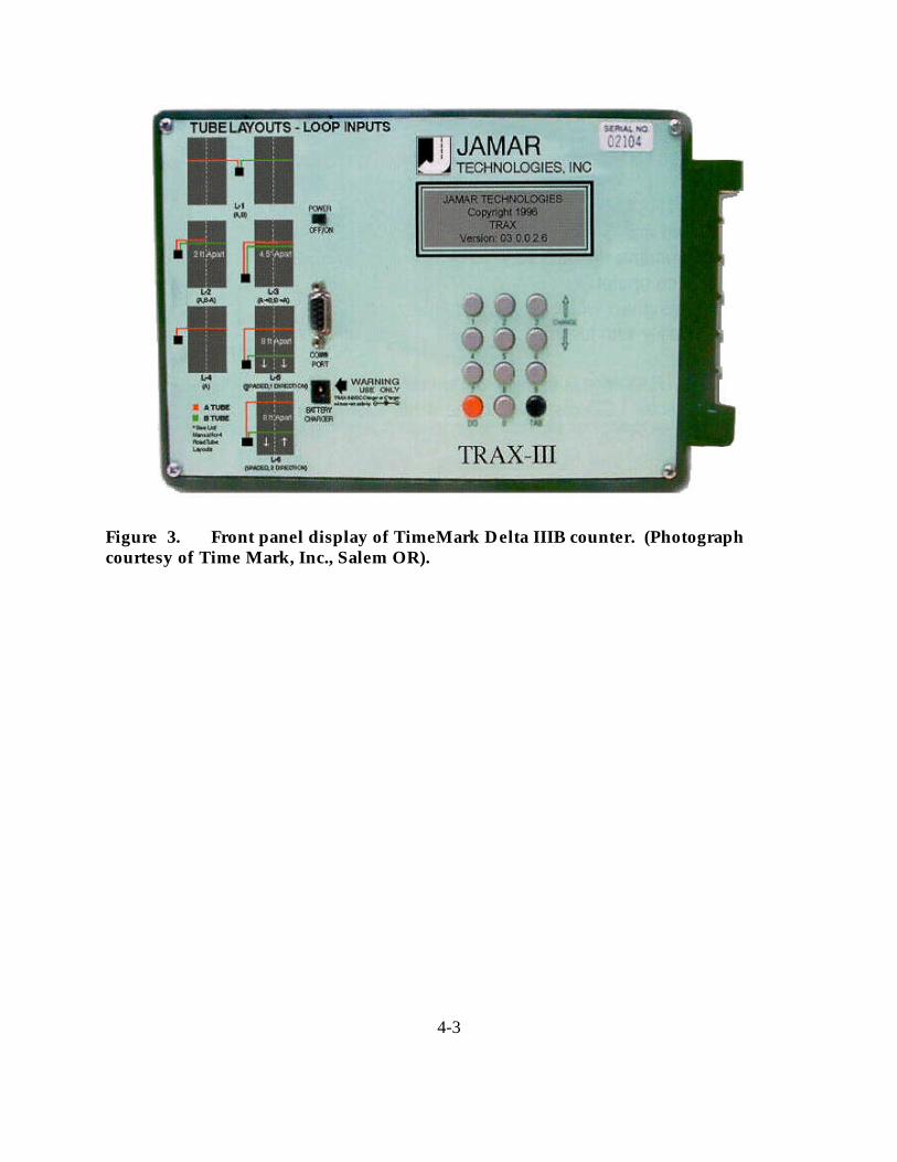
Installation Configuration
Figure 2 shows some of the road tube configurations utilized on single and multilane highways to
count and classify vehicles. Figure 3 displays the front panel of the TimeMark Delta IIIb
counter to indicate the ease with which collected data are matched to the tube layout.
Figure 2. Road tube configurations for single and multilane highways.(Photograph courtesy of Time Mark, Inc., Salem OR).
4-3
Figure 3. Front panel display of TimeMark Delta IIIB counter. (Photographcourtesy of Time Mark, Inc., Salem OR).
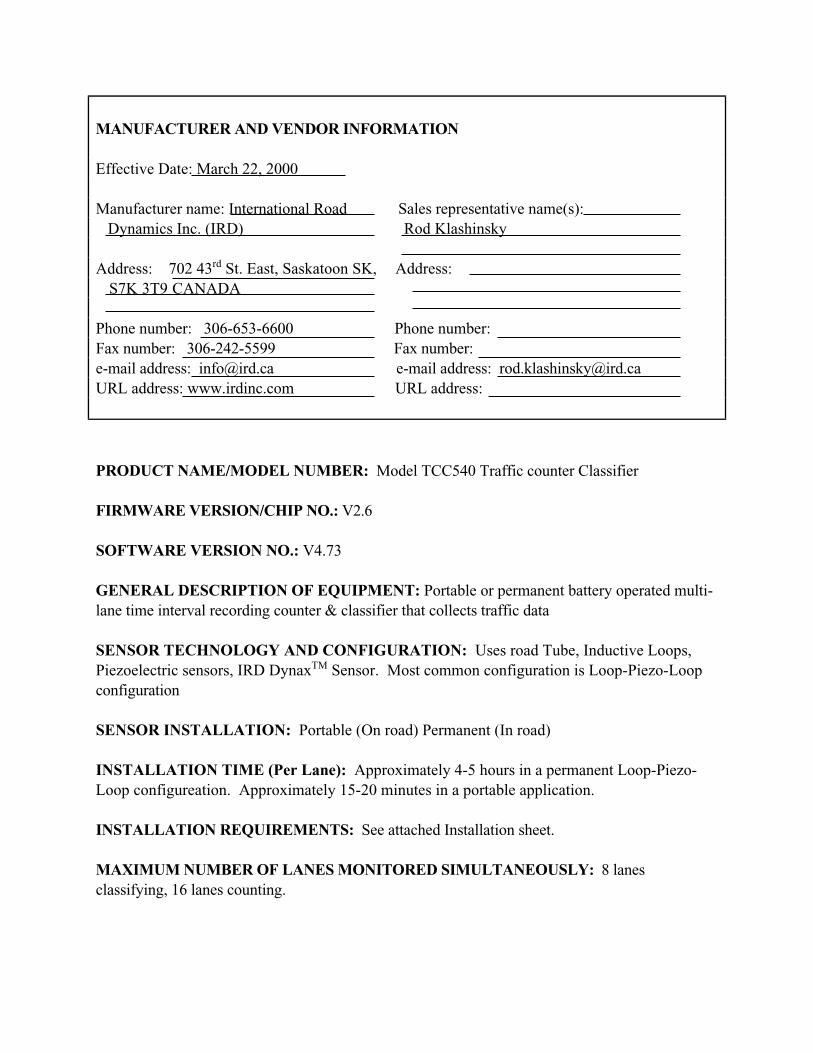
MANUFACTURER AND VENDOR INFORMATION
Effective Date: March 22, 2000
Manufacturer name: International Road Sales representative name(s):
Dynamics Inc. (IRD) Rod Klashinsky
Address: 702 43rd
St. East, Saskatoon SK, Address:
S7K 3T9 CANADA
Phone number: 306-653-6600 Phone number:
Fax number: 306-242-5599 Fax number:
e-mail address: [email protected] e-mail address: [email protected]
URL address: www.irdinc.com URL address:
PRODUCT NAME/MODEL NUMBER: Model TCC540 Traffic counter Classifier
FIRMWARE VERSION/CHIP NO.: V2.6
SOFTWARE VERSION NO.: V4.73
GENERAL DESCRIPTION OF EQUIPMENT: Portable or permanent battery operated multi-
lane time interval recording counter & classifier that collects traffic data
SENSOR TECHNOLOGY AND CONFIGURATION: Uses road Tube, Inductive Loops,
Piezoelectric sensors, IRD DynaxTM
Sensor. Most common configuration is Loop-Piezo-Loop
configuration
SENSOR INSTALLATION: Portable (On road) Permanent (In road)
INSTALLATION TIME (Per Lane): Approximately 4-5 hours in a permanent Loop-Piezo-
Loop configureation. Approximately 15-20 minutes in a portable application.
INSTALLATION REQUIREMENTS: See attached Installation sheet.
MAXIMUM NUMBER OF LANES MONITORED SIMULTANEOUSLY: 8 lanes
classifying, 16 lanes counting.

PRODUCT CAPABILITIES/FUNCTIONS: Collects vehicle traffic data, including vehicle
classification, speed, volume, headway and gap.
RECOMMENDED APPLICATIONS: Traffic Planning, Traffic Profile, Safety, and Audit.
POWER REQUIREMENTS (watts/amps): AC Power for 6 volt, 12 amp rechargeable battery.
POWER OPTIONS: Dual battery units, Solar package.
CLASSIFICATION ALGORITHMS: See attached specifications.
TELEMETRY: RS232 port with baud rates from 300-19,2000.
COMPUTER REQUIREMENTS: MSDOS.
DATA OUTPUT: IBM PC, Modem, Take-Away-Memory (TAM)
DATA OUTPUT FORMATS:
SUPPORTING DATA BASE MANAGEMENT SYSTEM: TrafmanTM
Software
EQUIPMENT AND INSTALLATION COSTS (One-lane and four-lane): Permanent One
lane — Approx. US $ 5,000, 4 lanes Approx. US $ 9,000.
STATES CURRENTLY USING THIS EQUIPMENT:
Country/State Contact name Telephone numberUSA/New Jersey
Canada/Saskatchewan
Canada/Manitoba
Canada/Ontario
Canada/Quebec
Canada/Nova Scotia
Canada/New Brunswick
Canada/Newfoundland.
Brazil
Uruguay
Venezuela
Columbia
India.

MANUFACTURER AND VENDOR INFORMATION
Effective Date: March 22, 2000
Manufacturer name: International Road Sales representative name(s):
Dynamics Rod Klashinsky
Address: 702 43rd
Street East, Saskatoon Address:
SK, S7K 3T9 CANADA
Phone number: 306-653-6600 Phone number:
Fax number: 306-242-5599 Fax number:
e-mail address: [email protected] e-mail address: [email protected]
URL address: www.irdinc.com URL address:
PRODUCT NAME/MODEL NUMBER: Model AS4XX Dynax¤Treadle Systems
FIRMWARE VERSION/CHIP NO.: Not applicable
SOFTWARE VERSION NO.: NA
GENERAL DESCRIPTION OF EQUIPMENT: Speed independent axle sensing systems.
SENSOR TECHNOLOGY AND CONFIGURATION: Pressure sensitive activation. Set in
frame, using 1,2,3 or four sensors
SENSOR INSTALLATION: Frame and Treadle system are permanent, sensor installation or
replacement, less than 20 minutes.
INSTALLATION TIME (Per Lane): 4-5 hours for Frame and Treadle systems; 20 minutes for
sensors.
INSTALLATION REQUIREMENTS: Contact IRD for information.
MAXIMUM NUMBER OF LANES MONITORED SIMULTANEOUSLY: One treadle per
lane (from stop and go traffic to 100 miles per hour).

PRODUCT CAPABILITIES/FUNCTIONS: Classification of vehicles by number of axles
detected.
RECOMMENDED APPLICATIONS: Toll plaza
POWER REQUIREMENTS (watts/amps): 12 volts DC (+/-5%)
POWER OPTIONS: With voltage regulator between 15 VDC to 28 VDC
CLASSIFICATION ALGORITHMS: NA (axle sensor output activation only)
TELEMETRY: NA
COMPUTER REQUIREMENTS:
DATA OUTPUT: B-420-4-A Dynax¤ Interface Circuit Board outputs sensor activation only.
DATA OUTPUT FORMATS:
SUPPORTING DATA BASE MANAGEMENT SYSTEM: Customers own data base
EQUIPMENT AND INSTALLATION COSTS (One-lane and four-lane): Installation &
equipment costs for 1 sensor 8 ft. systems US $ 6,500. For 4 sensors 10 foot system — US$
8,500.00
STATES CURRENTLY USING THIS EQUIPMENT:
Country/StateUSA/California
USA/Colorado
USA/Delaware
USA/Florida
USA/Maine
USA/Michigan
USA/New York
USA/New Jersey
USA/Oklahoma
USA/Texas
USA/Virginia
Canada/Nova Scotia
Canada/New Brunswick
Brazil
Columbia
Uruguay
India.

MANUFACTURER AND VENDOR INFORMATION
Effective Date: March 1, 2000
Manufacturer name: Sales representative name(s):
Traffic Monitoring Technologies Donald Dixon
Address: Address:
6510 Chantilly Drive, 1st
Floor 6510 Chantilly Drive, 1st Floor
Sykesville, Maryland 21784-8100 Sykesville, Maryland 21784-8100
Phone number: (410) 549-8779 Phone number: (410) 549-8779
Fax number: (410) 549-5113 Fax number: (410) 549-5113
e-mail address: [email protected] e-mail address: [email protected]
URL address: trafficmonitoring.com URL address: trafficmonitoring.com
PRODUCT NAME/MODEL NUMBER: The Blocker
FIRMWARE VERSION/CHIP NO.:
SOFTWARE VERSION NO.:
GENERAL DESCRIPTION OF EQUIPMENT: A cover and protector for low-profile or mini
road tube and the lead-in cable for electronic sensors. It incorporates a tough and durable
polymer that is flexible enough to contour the road yet strong enough to prevent vehicles from
compressing it. Used to get multi-lane volume/speed/class counts and WIM data from interior
lanes.
SENSOR TECHNOLOGY AND CONFIGURATION:
SENSOR INSTALLATION: The Blocker is placed over the road tube leading cable and taped
to the road to prevent movement.
INSTALLATION TIME (Per Lane): 2-5 minutes
INSTALLATION REQUIREMENTS: Road tape, dry conditions

MAXIMUM NUMBER OF LANES MONITORED SIMULTANEOUSLY: The Blocker
comes in 6 feet lengths, can be placed end-to-end to cover unlimited number of lanes.
PRODUCT CAPABILITIES/FUNCTIONS: Prevents vehicles from predicting in road tube
and protects lead-in cables of electronic sensors so counts and WIM data can be collected from
interior lanes.
RECOMMENDED APPLICATIONS: Where multiple lanes of data are needed and the road
tube or sensor must cross lanes with vehicular traffic. Also used to block out turn lanes for
intersection studies.
POWER REQUIREMENTS (watts/amps): None
POWER OPTIONS: None
CLASSIFICATION ALGORITHMS: N/A
TELEMETRY: N/A
COMPUTER REQUIREMENTS: N/A
DATA OUTPUT: N/A
DATA OUTPUT FORMATS: N/A
SUPPORTING DATA BASE MANAGEMENT SYSTEM: N/A
EQUIPMENT AND INSTALLATION COSTS (One-lane and four-lane): $138 per lane,
the Blocker is portable and can be used again and again over several applications
STATES CURRENTLY USING THIS EQUIPMENT:
Country/State Contact name Telephone numberUSA/PETCORP (Maryland) John Reed (410) 381-1995
USA/STS (Florida) Mark Knowles (800) 786-3374
USA/The Traffic Group Anthony Zuckert (410) 931-6600
USA/Traffic Data Services Ryan (800) 837-2562

MANUFACTURER AND VENDOR INFORMATION
Effective Date: 2/22/2000
Manufacturer name: Sales representative name(s):
TimeMark Inc. Mike Bonser, Kerry Penn, Tim Miner
Address: P.O. Box 12947 Address: Address:
Salem, OR 97309-0947
Phone number: (503) 363-2012 Phone number:
Fax number: (503) 363-1716 Fax number:
e-mail address: [email protected] e-mail address:
URL address: URL address:
PRODUCT NAME/MODEL NUMBER: Delta 111B & Delta 111L
FIRMWARE VERSION/CHIP NO.: 1.02
SOFTWARE VERSION NO.: 3.2.7
GENERAL DESCRIPTION OF EQUIPMENT: 4 tube counter, classifier
SENSOR TECHNOLOGY AND CONFIGURATION: Road tube
SENSOR INSTALLATION: Road tube hardware
INSTALLATION TIME (Per Lane): 5 min.
INSTALLATION REQUIREMENTS:
MAXIMUM NUMBER OF LANES MONITORED SIMULTANEOUSLY: Four
PRODUCT CAPABILITIES/FUNCTIONS: Bi-directional volume, speed, axle classification,
gap — all with one setting of counter under 5,000 ADT — volume counts on 4 lanes of traffic
simultaneously

RECOMMENDED APPLICATIONS: 2 lane — same way or bi-directional 5,000 A.D.T. and
above. 4 lane roadways for volume
POWER REQUIREMENTS (watts/amps):
POWER OPTIONS: 60 day rechargable gel cell battery
CLASSIFICATION ALGORITHMS:
TELEMETRY: If needed
COMPUTER REQUIREMENTS: 486 or better — Win 95, 98, NT
DATA OUTPUT:
DATA OUTPUT FORMATS: Comma delimited, strecter, TAS plus, GK and others as needed
SUPPORTING DATA BASE MANAGEMENT SYSTEM:
EQUIPMENT AND INSTALLATION COSTS (One-lane and four-lane): $1,950.00
STATES CURRENTLY USING THIS EQUIPMENT:
Country/State Contact name Telephone number
CONTACT TIMEMARK INC. FOR CURRENT LIST OF REFERENCES.

MANUFACTURER AND VENDOR INFORMATION
Effective Date: 2/22/2000
Manufacturer name: Sales representative name(s):
TimeMark Inc. Mike Bonser, Kerry Penn, Tim Miner
Address: P.O. Box 12947 Address: same
Salem, OR 97309-0947
Phone number: (503) 363-2012 Phone number:
Fax number: (503) 363-1716 Fax number:
e-mail address: [email protected] e-mail address:
URL address: URL address:
PRODUCT NAME/MODEL NUMBER: Gamma
FIRMWARE VERSION/CHIP NO.: 1.02
SOFTWARE VERSION NO.: 3.2.7
GENERAL DESCRIPTION OF EQUIPMENT: Two tube counter/classifier
SENSOR TECHNOLOGY AND CONFIGURATION: Road tube
SENSOR INSTALLATION: Road tube hardware
INSTALLATION TIME (Per Lane): 5 minutes
INSTALLATION REQUIREMENTS:
MAXIMUM NUMBER OF LANES MONITORED SIMULTANEOUSLY: Two
PRODUCT CAPABILITIES/FUNCTIONS: Bi - Directional volume, speed, axle classification,
gap — all with one setting of counter under 5,000 ADT
RECOMMENDED APPLICATIONS: 2 lane — same way or bi-directional roadways

POWER REQUIREMENTS (watts/amps):
POWER OPTIONS: 90 day rechargeable gel cell battery
CLASSIFICATION ALGORITHMS:
TELEMETRY:
COMPUTER REQUIREMENTS: 486 or better — Win 95, 98, NT
DATA OUTPUT:
DATA OUTPUT FORMATS: Comma delimited, strecter, TAS plus, GK and others as needed
SUPPORTING DATA BASE MANAGEMENT SYSTEM:
EQUIPMENT AND INSTALLATION COSTS (One-lane and four-lane): $1,650.00
STATES CURRENTLY USING THIS EQUIPMENT:
Country/State Contact name Telephone number
CONTACT TIMEMARK INC. FOR CURRENT LIST OF REFERENCES.

MANUFACTURER AND VENDOR INFORMATION
Effective Date: 2/22/2000
Manufacturer name: Sales representative name(s):
TimeMark Inc. Mike Bonser, Kerry Penn, Tim Miner
Address: P.O. Box 12947 Address: same
Salem, OR 97309-0947
Phone number: (503) 363-2012 Phone number:
Fax number: (503) 363-1716 Fax number:
e-mail address: [email protected] e-mail address:
URL address: URL address:
PRODUCT NAME/MODEL NUMBER: Beta
FIRMWARE VERSION/CHIP NO.: 1.02
SOFTWARE VERSION NO.: 3.2.7
GENERAL DESCRIPTION OF EQUIPMENT: Traffic counter volume only road tube
SENSOR TECHNOLOGY AND CONFIGURATION: Road tube
SENSOR INSTALLATION: Road tube hardware
INSTALLATION TIME (Per Lane): 5 minutes
INSTALLATION REQUIREMENTS:
MAXIMUM NUMBER OF LANES MONITORED SIMULTANEOUSLY: Two
PRODUCT CAPABILITIES/FUNCTIONS: Bi - Directional volume count
RECOMMENDED APPLICATIONS: Roadway

POWER REQUIREMENTS (watts/amps):
POWER OPTIONS: Rechargeable GSL cell battery
CLASSIFICATION ALGORITHMS:
TELEMETRY: If needed
COMPUTER REQUIREMENTS:
DATA OUTPUT:
DATA OUTPUT FORMATS: Comma delimited, strecter, TAS plus, GK and others as needed
SUPPORTING DATA BASE MANAGEMENT SYSTEM:
EQUIPMENT AND INSTALLATION COSTS (One-lane and four-lane): $1,550.00
STATES CURRENTLY USING THIS EQUIPMENT:
Country/State Contact name Telephone number
CONTACT TIMEMARK INC. FOR CURRENT LIST OF REFERENCES.

4-4
Inductive Loop Detectors
The inductive loop detector (ILD) is the most common sensor used in traffic management
applications. Its size and shape vary, including the 5-ft by 5-ft or 6-ft by 6-ft square loops, 6-ft
diameter round loops, and rectangular configurations having a 6-ft width and variable length
(Gordon, et. al., 1996). Figure 4 shows the principal components of an inductive loop detector:
one or more turns of insulated wire buried in a shallow saw-cut in the roadway, a lead-in cable
that runs from a roadside pull box to the controller cabinet, and an electronics unit located in the
controller cabinet.
Principles of Operation
The wire loop is excited with signals whose frequencies range from 10 KHz to 50 KHz and
functions as an inductive element in conjunction with the electronics unit. When a vehicle stops
on or passes over the loop, the inductance of the loop is decreased. The decreased inductance
increases the oscillation frequency and causes the electronics unit to send a pulse to the
controller, indicating the presence or passage of a vehicle.
Applications and Uses
The data supplied by conventional inductive loop detectors are vehicle passage, presence, count,
and occupancy. Although loops cannot directly measure speed, speed can be determined using a
two-loop speed trap or a single loop detector and an algorithm whose inputs are loop length,
average vehicle length, time over the detector, and number of vehicles counted. Vehicle
classification is supported by newer versions of the inductive loop containing electronics units
that excite the wire loop at the higher frequencies that identify specific metal portions on the
vehicle.

4-5
Advantages
The operation of inductive loop sensors is well understood and their application for providing
basic traffic parameters (volume, presence, occupancy, speed, headway, and gap) represents a
mature technology. As was the case with the pneumatic road tube, the equipment cost of
inductive loop sensors is low when compared to non-intrusive sensor technologies. Another
advantage of inductive loop sensors is their ability to satisfy a large variety of applications due to
their flexible design.
Disadvantages
The drawbacks to the use of inductive loop sensors include disruption of traffic for installation
and repair and failures associated with installations in poor road surfaces and use of substandard
installation procedures. In many instances multiple detectors are usually required to instrument a
location. In addition, resurfacing of roadways and utility repair can also create the need to
reinstall these types of sensors. Also, wire loops are subject to stresses of traffic and
temperature.

4-6
Figure 4. Principal components of an inductive loop detector.
Controller cabinet
Lead-in conduit
Pullbox
Conduit-to-curb run
Shielded lead-in cable
Splice in pullbox
Twisted wire to suppresselectrical interferenceLoop wire plan
3 turns
Roadway section
Loop sawcut plan
Roa
dway
cen
terli
ne
Cur
b lin
e
Electronics unit
12 ft
3 ft 6 ft 3 ft
(Source: Gordon, R.L., R.A. Reiss, H. Haenel, E.R. Case, R.L. French, A. Mohaddes, and R. Wolcott, Traffic Control Systems Handbook, FHWA-SA-95-032, Federal Highway Administration, U.S. Department of Transportation, Washington, D.C., Feb. 1996.)
1 ft = 0.305 m

MANUFACTURER AND VENDOR INFORMATION
Effective Date:
Manufacturer name: Sales representative name(s):
Never Fail Loop Systems. Roland Smits
Address: 285 N. Hancock Address: same
Portland, OR 97227
Phone number: (503) 288-8871 Phone number
Fax number: (503) 288-0274 Fax number:
e-mail address: [email protected] e-mail address: [email protected]
URL address: www.neverfail.com URL address:
PRODUCT NAME/MODEL NUMBER: Never-Fail
FIRMWARE VERSION/CHIP NO.: N/A
SOFTWARE VERSION NO.: N/A
GENERAL DESCRIPTION OF EQUIPMENT: Preformed Traffic Detection Loops
SENSOR TECHNOLOGY AND CONFIGURATION: Inductive Loops
SENSOR INSTALLATION: In-ground
INSTALLATION TIME (Per Lane): New pavement aps 10 minutes, existing pavement
approximately 1 hour
INSTALLATION REQUIREMENTS:
MAXIMUM NUMBER OF LANES MONITORED SIMULTANEOUSLY: No maximum
PRODUCT CAPABILITIES/FUNCTIONS: Traffic control, preemption, volume count, speed
count, intersection control, traffic jam detection

RECOMMENDED APPLICATIONS: Intersections, freeways
POWER REQUIREMENTS (watts/amps): N/A
POWER OPTIONS: N/A
CLASSIFICATION ALGORITHMS: N/A
TELEMETRY: N/A
COMPUTER REQUIREMENTS: N/A
DATA OUTPUT:
DATA OUTPUT FORMATS:
SUPPORTING DATA BASE MANAGEMENT SYSTEM:
EQUIPMENT AND INSTALLATION COSTS (One-lane and four-lane):
STATES CURRENTLY USING THIS EQUIPMENT:
Country/State Contact name Telephone number
CONTACT NEVERFAIL LOOP SYSTEMS FOR CURRENT LIST OF REFERENCES.

MANUFACTURER AND VENDOR INFORMATION
Effective Date: 3/1/00
Manufacturer name: Peek Traffic Inc. Sales representative name(s):
Bill Ippolito & Rob Gaines
Address: 1500 N. Washington Blvd. Address:
Sarasota, FL 34236
Phone number: (941) 951-0221 Phone number: (301) 733-2125
Fax number: (941) 365-0837 Fax number: (301) 745-3558
e-mail address: [email protected] e-mail address: [email protected]
URL address: URL address:
PRODUCT NAME/MODEL NUMBER: IDRIS/ADR 6000/Prism
FIRMWARE VERSION/CHIP NO.:
SOFTWARE VERSION NO.:
GENERAL DESCRIPTION OF EQUIPMENT: Smart loop system. Roadside mounted rack.
Loop based classifier.
SENSOR TECHNOLOGY AND CONFIGURATION: Loops, dependent on application
SENSOR INSTALLATION:
INSTALLATION TIME (Per Lane): 4 hours
INSTALLATION REQUIREMENTS:
MAXIMUM NUMBER OF LANES MONITORED SIMULTANEOUSLY: Eight
PRODUCT CAPABILITIES/FUNCTIONS: Classification, axle count, vehicle count, lane
designation, enforcement trigger

RECOMMENDED APPLICATIONS: Manual toll lanes, express toll lanes, DOT classification
in congestion
POWER REQUIREMENTS (watts/amps): Less than .1 amp
POWER OPTIONS: Currently A/C
CLASSIFICATION ALGORITHMS: IDRIS; vehicle by vehicle for toll booths
TELEMETRY: Yes
COMPUTER REQUIREMENTS: Data analysis done in outstation
DATA OUTPUT: Based on application
DATA OUTPUT FORMATS:
SUPPORTING DATA BASE MANAGEMENT SYSTEM:
EQUIPMENT AND INSTALLATION COSTS (One-lane and four-lane):
STATES CURRENTLY USING THIS EQUIPMENT:
Country/State Contact name Telephone number
CONTACT PEEK TRAFFIC FOR CURRENT LIST OF REFERENCES.

MANUFACTURER AND VENDOR INFORMATION
Effective Date: 6/1/00
Manufacturer name: Peek Traffic Inc. Sales representative name(s):
Rob Gaines
Debbie Rupp
Address: 1500 N. Washington Blvd. Address: same
Sarasota, FL 34236
Phone number: (941) 366-8770 Phone number:
Fax number: (941) 365-0837 Fax number:
e-mail address: [email protected] e-mail address:
URL address: URL address:
PRODUCT NAME/MODEL NUMBER: 224 GP7 (New Product!)
FIRMWARE VERSION/CHIP NO.:
SOFTWARE VERSION NO.:
GENERAL DESCRIPTION OF EQUIPMENT: 2 channel inductive loop detector. For TS-1
and TS-2
SENSOR TECHNOLOGY AND CONFIGURATION: Monitors the change of inductance and
frequency
SENSOR INSTALLATION: Plug in module, plugs into card rack
INSTALLATION TIME (Per Lane): Minimal
INSTALLATION REQUIREMENTS: Must be connected to in-ground inductive loop
MAXIMUM NUMBER OF LANES MONITORED SIMULTANEOUSLY: Two

PRODUCT CAPABILITIES/FUNCTIONS: Monitors loop coil for inductive changes.
Outputs on passage of vehicle over buried loop of wire.
RECOMMENDED APPLICATIONS: Intersection and freeway control. Used in traffic signal
systems.
POWER REQUIREMENTS (watts/amps): 10 to 30 VDC
POWER OPTIONS:
CLASSIFICATION ALGORITHMS:
TELEMETRY:
COMPUTER REQUIREMENTS:
DATA OUTPUT:
DATA OUTPUT FORMATS:
SUPPORTING DATA BASE MANAGEMENT SYSTEM:
EQUIPMENT AND INSTALLATION COSTS (One-lane and four-lane):
STATES CURRENTLY USING THIS EQUIPMENT:
Country/State Contact name Telephone number
CONTACT PEEK TRAFFIC FOR CURRENT LIST OF REFERENCES.

MANUFACTURER AND VENDOR INFORMATION
Effective Date: 6/1/00
Manufacturer name: Peek Traffic Inc. Sales representative name(s):
Rob Gaines
Debbie Rupp
Address: 1500 N. Washington Blvd. Address: same
Sarasota, FL 34236
Phone number: (941) 366-8770 Phone number:
Fax number: (941) 365-0837 Fax number:
e-mail address: [email protected] e-mail address:
URL address: URL address:
PRODUCT NAME/MODEL NUMBER: 224T GP7 (New Product!)
FIRMWARE VERSION/CHIP NO.:
SOFTWARE VERSION NO.:
GENERAL DESCRIPTION OF EQUIPMENT: 4 channel inductive loop detector. With extend
and delay timers. For TS-1 and TS-2
SENSOR TECHNOLOGY AND CONFIGURATION: Monitors the change of inductance and
frequency
SENSOR INSTALLATION: Plug in module, plugs into card rack
INSTALLATION TIME (Per Lane): Minimal
INSTALLATION REQUIREMENTS: Must be connected to in ground inductive loop
MAXIMUM NUMBER OF LANES MONITORED SIMULTANEOUSLY: Four
PRODUCT CAPABILITIES/FUNCTIONS: Monitors loop coil for inductive changes.
Outputs on passage of vehicle over buried loop of wire.

RECOMMENDED APPLICATIONS: Intersection and freeway control. Used in traffic signal
systems.
POWER REQUIREMENTS (watts/amps): 10 — 30 VDC
POWER OPTIONS:
CLASSIFICATION ALGORITHMS:
TELEMETRY:
COMPUTER REQUIREMENTS:
DATA OUTPUT:
DATA OUTPUT FORMATS:
SUPPORTING DATA BASE MANAGEMENT SYSTEM:
EQUIPMENT AND INSTALLATION COSTS (One-lane and four-lane):
STATES CURRENTLY USING THIS EQUIPMENT:
Country/State Contact name Telephone number
CONTACT PEEK TRAFFIC FOR CURRENT LIST OF REFERENCES.

MANUFACTURER AND VENDOR INFORMATION
Effective Date: 6/1/00
Manufacturer name: Peek Traffic Inc. Sales representative name(s):
Rob Gaines
Debbie Rupp
Address: 1500 N. Washington Blvd. Address: same
Sarasota, FL 34236
Phone number: (941) 366-8770 Phone number
Fax number: (941) 365-0837 Fax number:
e-mail address: [email protected] e-mail address:
URL address: URL address:
PRODUCT NAME/MODEL NUMBER: 222TGP7
FIRMWARE VERSION/CHIP NO.:
SOFTWARE VERSION NO.:
GENERAL DESCRIPTION OF EQUIPMENT: Two channel inductive loop detector. With
extend and delay timers. For TS-1 and TS-2
SENSOR TECHNOLOGY AND CONFIGURATION: Monitors the change of inductance and
frequency
SENSOR INSTALLATION: Plug in module, plugs into card rack
INSTALLATION TIME (Per Lane): Minimal
INSTALLATION REQUIREMENTS: Must be connected to in ground inductive loop
MAXIMUM NUMBER OF LANES MONITORED SIMULTANEOUSLY: Two
PRODUCT CAPABILITIES/FUNCTIONS: Monitors loop coil for inductive changes.
Outputs on passage of vehicle over buried loop of wire.

RECOMMENDED APPLICATIONS: Intersection and freeway control. Used in traffic signal
systems.
POWER REQUIREMENTS (watts/amps): 10 — 30 VDC
POWER OPTIONS:
CLASSIFICATION ALGORITHMS:
TELEMETRY:
COMPUTER REQUIREMENTS:
DATA OUTPUT:
DATA OUTPUT FORMATS:
SUPPORTING DATA BASE MANAGEMENT SYSTEM:
EQUIPMENT AND INSTALLATION COSTS (One-lane and four-lane):
STATES CURRENTLY USING THIS EQUIPMENT:
Country/State Contact name Telephone number
CONTACT PEEK TRAFFIC FOR CURRENT LIST OF REFERENCES.

MANUFACTURER AND VENDOR INFORMATION
Effective Date: 6/1/00
Manufacturer name: Peek Traffic Inc. Sales representative name(s):
Rob Gaines
Debbie Rupp
Address: 1500 N. Washington Blvd. Address: same
Sarasota, FL 34236
Phone number: (941) 366-8770 Phone number:
Fax number: (941) 365-0837 Fax number:
e-mail address: [email protected] e-mail address:
URL address: URL address:
PRODUCT NAME/MODEL NUMBER: 222 GP7
FIRMWARE VERSION/CHIP NO.:
SOFTWARE VERSION NO.:
GENERAL DESCRIPTION OF EQUIPMENT: 2 channel inductive loop detector. For TS-1
and TS-2
SENSOR TECHNOLOGY AND CONFIGURATION: Monitors the change of inductance and
frequency
SENSOR INSTALLATION: Plug in module, plugs into card rack
INSTALLATION TIME (Per Lane): Minimal
INSTALLATION REQUIREMENTS: Must be connected to in ground inductive loop
MAXIMUM NUMBER OF LANES MONITORED SIMULTANEOUSLY: Two

PRODUCT CAPABILITIES/FUNCTIONS: Monitors loop coil for inductive changes.
Outputs on passage of vehicle over buried loop of wire.
RECOMMENDED APPLICATIONS: Intersection and freeway control. Used in traffic signal
systems.
POWER REQUIREMENTS (watts/amps): 10 — 30 VDC
POWER OPTIONS:
CLASSIFICATION ALGORITHMS:
TELEMETRY:
COMPUTER REQUIREMENTS:
DATA OUTPUT:
DATA OUTPUT FORMATS:
SUPPORTING DATA BASE MANAGEMENT SYSTEM:
EQUIPMENT AND INSTALLATION COSTS (One-lane and four-lane):
STATES CURRENTLY USING THIS EQUIPMENT:
Country/State Contact name Telephone number
CONTACT PEEK TRAFFIC FOR CURRENT LIST OF REFERENCES.

MANUFACTURER AND VENDOR INFORMATION
Effective Date: 2/28/00
Manufacturer name: Peek Traffic Inc. Sales representative name(s):
Rob Gaines
Debbie Rupp
Address: 1500 N. Washington Blvd. Address: same
Sarasota, FL 34236
Phone number: (941) 366-8770 Phone number
Fax number: (941) 365-0837 Fax number:
e-mail address: [email protected] e-mail address:
URL address: URL address:
PRODUCT NAME/MODEL NUMBER: 224 GP5
FIRMWARE VERSION/CHIP NO.:
SOFTWARE VERSION NO.:
GENERAL DESCRIPTION OF EQUIPMENT: 4 channel inductive loop detector.
SENSOR TECHNOLOGY AND CONFIGURATION: Monitors the change of inductance and
frequency
SENSOR INSTALLATION: Plug in module, plugs into card rack
INSTALLATION TIME (Per Lane): Minimal
INSTALLATION REQUIREMENTS: Must be connected to in ground inductive loop
MAXIMUM NUMBER OF LANES MONITORED SIMULTANEOUSLY: Four
PRODUCT CAPABILITIES/FUNCTIONS: Monitors loop coil for inductive changes.
Outputs on passage of vehicle over buried loop of wire.

RECOMMENDED APPLICATIONS: Intersection and freeway control. Used in traffic signal
systems.
POWER REQUIREMENTS (watts/amps): 10.8 to 28.8 VDC 80mA maximum
POWER OPTIONS:
CLASSIFICATION ALGORITHMS:
TELEMETRY:
COMPUTER REQUIREMENTS:
DATA OUTPUT:
DATA OUTPUT FORMATS:
SUPPORTING DATA BASE MANAGEMENT SYSTEM:
EQUIPMENT AND INSTALLATION COSTS (One-lane and four-lane):
STATES CURRENTLY USING THIS EQUIPMENT:
Country/State Contact name Telephone numberUSA/California Bob McMillan (916) 654-4385
USA/New York Mike Naumiec (518) 783-7746

MANUFACTURER AND VENDOR INFORMATION
Effective Date: 2/28/00
Manufacturer name: Peek Traffic Inc. Sales representative name(s):
Rob Gaines
Debbie Rupp
Address: 1500 N. Washington Blvd. Address: same
Sarasota, FL 34236
Phone number: (941) 366-8770 Phone number:
Fax number: (941) 365-0837 Fax number:
e-mail address: [email protected] e-mail address:
URL address: URL address:
PRODUCT NAME/MODEL NUMBER: 222GP6
FIRMWARE VERSION/CHIP NO.:
SOFTWARE VERSION NO.:
GENERAL DESCRIPTION OF EQUIPMENT: 2 channel inductive loop detector.
SENSOR TECHNOLOGY AND CONFIGURATION: Monitors the change of inductance and
frequency
SENSOR INSTALLATION: Plug in module, plugs into card rack
INSTALLATION TIME (Per Lane): Minimal
INSTALLATION REQUIREMENTS: Must be connected to in ground inductive loop
MAXIMUM NUMBER OF LANES MONITORED SIMULTANEOUSLY: Two
PRODUCT CAPABILITIES/FUNCTIONS: Monitors loop coil for inductive changes.
Outputs on passage of vehicle over buried loop of wire.

RECOMMENDED APPLICATIONS: Both intersection and freeway control with 170 & 2070
controllers. Used in traffic signal systems.
POWER REQUIREMENTS (watts/amps): 10.8 to 28.8 VDC 80mA maximum
POWER OPTIONS:
CLASSIFICATION ALGORITHMS:
TELEMETRY:
COMPUTER REQUIREMENTS:
DATA OUTPUT:
DATA OUTPUT FORMATS:
SUPPORTING DATA BASE MANAGEMENT SYSTEM:
EQUIPMENT AND INSTALLATION COSTS (One-lane and four-lane):
STATES CURRENTLY USING THIS EQUIPMENT:
Country/State Contact name Telephone numberUSA/California Bob McMillan (916) 654-4385
USA/New York Mike Naumiec (518) 783-7746
MANUFACTURER AND VENDOR INFORMATION
Effective Date: 8/1/00
Manufacturer name: Peek Traffic Inc. Sales representative name(s):
Rob Gaines
Debbie Rupp
Address: 1500 N. Washington Blvd. Address: same
Sarasota, FL 34236
Phone number: (941) 366-8770 Phone number:
Fax number: (941) 365-0837 Fax number:
e-mail address: [email protected] e-mail address:
URL address: URL address:
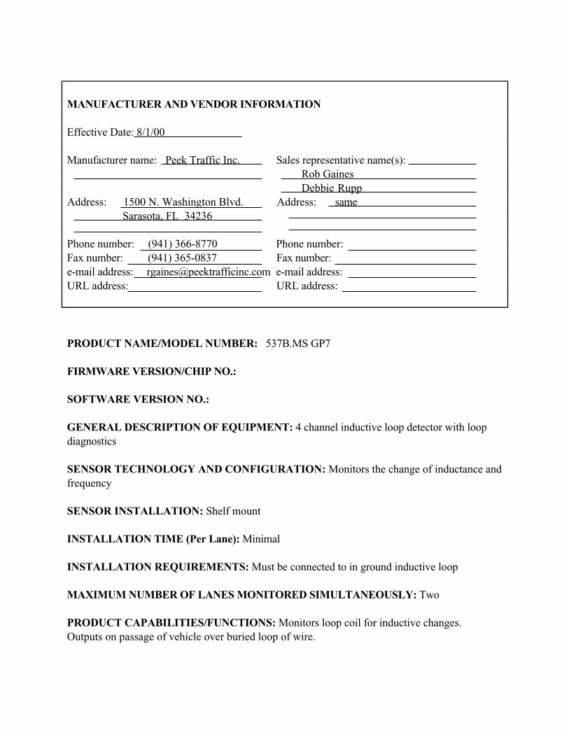
PRODUCT NAME/MODEL NUMBER: 537B.MS GP7
FIRMWARE VERSION/CHIP NO.:
SOFTWARE VERSION NO.:
GENERAL DESCRIPTION OF EQUIPMENT: 4 channel inductive loop detector with loop
diagnostics
SENSOR TECHNOLOGY AND CONFIGURATION: Monitors the change of inductance and
frequency
SENSOR INSTALLATION: Shelf mount
INSTALLATION TIME (Per Lane): Minimal
INSTALLATION REQUIREMENTS: Must be connected to in ground inductive loop
MAXIMUM NUMBER OF LANES MONITORED SIMULTANEOUSLY: Two
PRODUCT CAPABILITIES/FUNCTIONS: Monitors loop coil for inductive changes.
Outputs on passage of vehicle over buried loop of wire.

RECOMMENDED APPLICATIONS: Intersection and freeway control. Used in traffic signal
systems.
POWER REQUIREMENTS (watts/amps): 110 VAC
POWER OPTIONS:
CLASSIFICATION ALGORITHMS:
TELEMETRY:
COMPUTER REQUIREMENTS:
DATA OUTPUT:
DATA OUTPUT FORMATS:
SUPPORTING DATA BASE MANAGEMENT SYSTEM:
EQUIPMENT AND INSTALLATION COSTS (One-lane and four-lane):
STATES CURRENTLY USING THIS EQUIPMENT:
Country/State Contact name Telephone numberUSA/Florida
USA/Illinois
USA/Wisconsin
Canada/Ontario

MANUFACTURER AND VENDOR INFORMATION
Effective Date: 8/1/00
Manufacturer name: Peek Traffic Inc. Sales representative name(s):
Rob Gaines
Debbie Rupp
Address: 1500 N. Washington Blvd. Address: same
Sarasota, FL 34236
Phone number: (941) 366-8770 Phone number:
Fax number: (941) 365-0837 Fax number:
e-mail address: [email protected] e-mail address:
URL address: URL address:
PRODUCT NAME/MODEL NUMBER: 537T/MS GP7
FIRMWARE VERSION/CHIP NO.:
SOFTWARE VERSION NO.:
GENERAL DESCRIPTION OF EQUIPMENT: 4 channel inductive loop detector. With extend
and delay timers.
SENSOR TECHNOLOGY AND CONFIGURATION: Monitors the change of inductance and
frequency
SENSOR INSTALLATION: Shelf mount
INSTALLATION TIME (Per Lane): Minimal
INSTALLATION REQUIREMENTS: Must be connected to in ground inductive loop
MAXIMUM NUMBER OF LANES MONITORED SIMULTANEOUSLY: 2
PRODUCT CAPABILITIES/FUNCTIONS: Monitors loop coil for inductive changes.
Outputs on passage of vehicle over buried loop of wire.

RECOMMENDED APPLICATIONS: Intersection and freeway control
POWER REQUIREMENTS (watts/amps): 110VAC
POWER OPTIONS:
CLASSIFICATION ALGORITHMS:
TELEMETRY:
COMPUTER REQUIREMENTS:
DATA OUTPUT:
DATA OUTPUT FORMATS:
SUPPORTING DATA BASE MANAGEMENT SYSTEM:
EQUIPMENT AND INSTALLATION COSTS (One-lane and four-lane):
STATES CURRENTLY USING THIS EQUIPMENT:
Country/State Contact name Telephone number
CONTACT PEEK TRAFFIC FOR CURRENT LIST OF REFERENCES.

MANUFACTURER AND VENDOR INFORMATION
Effective Date: 8/1/00
Manufacturer name: Peek Traffic Inc. Sales representative name(s):
Rob Gaines
Debbie Rupp
Address: 1500 N. Washington Blvd. Address: same
Sarasota, FL 34236
Phone number: (941) 366-8770 Phone number:
Fax number: (941) 365-0837 Fax number:
e-mail address: [email protected] e-mail address:
URL address: URL address:
PRODUCT NAME/MODEL NUMBER: 536B/MS GP7
FIRMWARE VERSION/CHIP NO.:
SOFTWARE VERSION NO.:
GENERAL DESCRIPTION OF EQUIPMENT: 2 channel inductive loop detector.
SENSOR TECHNOLOGY AND CONFIGURATION: Monitors the change of inductance and
frequency
SENSOR INSTALLATION: Shelf mount
INSTALLATION TIME (Per Lane): Minimal
INSTALLATION REQUIREMENTS: Must be connected to in ground inductive loop
MAXIMUM NUMBER OF LANES MONITORED SIMULTANEOUSLY: 2
PRODUCT CAPABILITIES/FUNCTIONS: Monitors loop coil for inductive changes.
Outputs on passage of vehicle over buried loop of wire.

RECOMMENDED APPLICATIONS: Intersection and freeway control. Used in traffic signal
systems.
POWER REQUIREMENTS (watts/amps): 110 VAC
POWER OPTIONS:
CLASSIFICATION ALGORITHMS:
TELEMETRY:
COMPUTER REQUIREMENTS:
DATA OUTPUT:
DATA OUTPUT FORMATS:
SUPPORTING DATA BASE MANAGEMENT SYSTEM:
EQUIPMENT AND INSTALLATION COSTS (One-lane and four-lane):
STATES CURRENTLY USING THIS EQUIPMENT:
Country/State Contact name Telephone number
CONTACT PEEK TRAFFIC FOR CURRENT LIST OF REFERENCES.

MANUFACTURER AND VENDOR INFORMATION
Effective Date: 8/1/00
Manufacturer name: Peek Traffic Inc. Sales representative name(s):
Rob Gaines
Debbie Rupp
Address: 1500 N. Washington Blvd. Address: same
Sarasota, FL 34236
Phone number: (941) 366-8770 Phone number:
Fax number: (941) 365-0837 Fax number:
e-mail address: [email protected] e-mail address:
URL address: URL address:
PRODUCT NAME/MODEL NUMBER: 535B/MS GP7
FIRMWARE VERSION/CHIP NO.:
SOFTWARE VERSION NO.:
GENERAL DESCRIPTION OF EQUIPMENT:1 channel inductive loop detector.
SENSOR TECHNOLOGY AND CONFIGURATION: Monitors the change of inductance and
frequency
SENSOR INSTALLATION: Shelf mount
INSTALLATION TIME (Per Lane): Minimal
INSTALLATION REQUIREMENTS: Must be connected to in ground inductive loop
MAXIMUM NUMBER OF LANES MONITORED SIMULTANEOUSLY: One

PRODUCT CAPABILITIES/FUNCTIONS: Monitors loop coil for inductive changes.
Outputs on passage of vehicle over buried loop of wire.
RECOMMENDED APPLICATIONS: Intersection and freeway control. Used in traffic signal
systems.
POWER REQUIREMENTS (watts/amps): 110 VAC
POWER OPTIONS:
CLASSIFICATION ALGORITHMS:
TELEMETRY:
COMPUTER REQUIREMENTS:
DATA OUTPUT:
DATA OUTPUT FORMATS:
SUPPORTING DATA BASE MANAGEMENT SYSTEM:
EQUIPMENT AND INSTALLATION COSTS (One-lane and four-lane):
STATES CURRENTLY USING THIS EQUIPMENT:
Country/State Contact name Telephone number
CONTACT PEEK TRAFFIC FOR CURRENT LIST OF REFERENCES.

MANUFACTURER AND VENDOR INFORMATION
Effective Date: 8/1/00
Manufacturer name: Peek Traffic Inc. Sales representative name(s):
Rob Gaines
Debbie Rupp
Address: 1500 N. Washington Blvd. Address: same
Sarasota, FL 34236
Phone number: (941) 366-8770 Phone number:
Fax number: (941) 365-0837 Fax number:
e-mail address: [email protected] e-mail address:
URL address: URL address:
PRODUCT NAME/MODEL NUMBER: 535T/MS GP7
FIRMWARE VERSION/CHIP NO.:
SOFTWARE VERSION NO.:
GENERAL DESCRIPTION OF EQUIPMENT: Single channel inductive loop detector with
extend and delay timing.
SENSOR TECHNOLOGY AND CONFIGURATION: Monitors the change of inductance and
frequency
SENSOR INSTALLATION: Shelf mount
INSTALLATION TIME (Per Lane): Minimal
INSTALLATION REQUIREMENTS: Must be connected to in ground inductive loop
MAXIMUM NUMBER OF LANES MONITORED SIMULTANEOUSLY: One
PRODUCT CAPABILITIES/FUNCTIONS: Monitors loop coil for inductive changes.
Outputs on passage of vehicle over buried loop of wire.

RECOMMENDED APPLICATIONS: Intersection and freeway control
POWER REQUIREMENTS (watts/amps): 110 VAC
POWER OPTIONS:
CLASSIFICATION ALGORITHMS:
TELEMETRY:
COMPUTER REQUIREMENTS:
DATA OUTPUT:
DATA OUTPUT FORMATS:
SUPPORTING DATA BASE MANAGEMENT SYSTEM:
EQUIPMENT AND INSTALLATION COSTS (One-lane and four-lane):
STATES CURRENTLY USING THIS EQUIPMENT:
Country/State Contact name Telephone number
CONTACT PEEK TRAFFIC FOR CURRENT LIST OF REFERENCES.
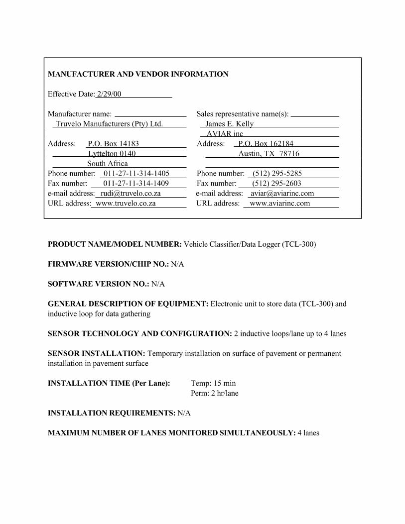
MANUFACTURER AND VENDOR INFORMATION
Effective Date: 2/29/00
Manufacturer name: Sales representative name(s):
Truvelo Manufacturers (Pty) Ltd. James E. Kelly
AVIAR inc
Address: P.O. Box 14183 Address: P.O. Box 162184
Lyttelton 0140 Austin, TX 78716
South Africa
Phone number: 011-27-11-314-1405 Phone number: (512) 295-5285
Fax number: 011-27-11-314-1409 Fax number: (512) 295-2603
e-mail address: [email protected] e-mail address: [email protected]
URL address: www.truvelo.co.za URL address: www.aviarinc.com
PRODUCT NAME/MODEL NUMBER: Vehicle Classifier/Data Logger (TCL-300)
FIRMWARE VERSION/CHIP NO.: N/A
SOFTWARE VERSION NO.: N/A
GENERAL DESCRIPTION OF EQUIPMENT: Electronic unit to store data (TCL-300) and
inductive loop for data gathering
SENSOR TECHNOLOGY AND CONFIGURATION: 2 inductive loops/lane up to 4 lanes
SENSOR INSTALLATION: Temporary installation on surface of pavement or permanent
installation in pavement surface
INSTALLATION TIME (Per Lane): Temp: 15 min
Perm: 2 hr/lane
INSTALLATION REQUIREMENTS: N/A
MAXIMUM NUMBER OF LANES MONITORED SIMULTANEOUSLY: 4 lanes

PRODUCT CAPABILITIES/FUNCTIONS: Vehicle number, date, time, direction, vehicle
class, length, headway, data of 20,000 individual vehicles.
RECOMMENDED APPLICATIONS: Vehicle classification, vehicle following distances,
queuing and lane occupancy.
POWER REQUIREMENTS (watts/amps): 6 volt internal battery (rechargeable from 12 volt
battery, commercial power, or solar energy)
POWER OPTIONS: See above
CLASSIFICATION ALGORITHMS: Vehicle pattern recognition s in light, medium, heavy or
light, rigid trucks and buses, trucks and trailers, tractor and semitrailer, multitrailer heavy vehicles
TELEMETRY: RS232 serial port and modem
COMPUTER REQUIREMENTS: Compatible PC
DATA OUTPUT: See Product Capabilities
DATA OUTPUT FORMATS: N/A
SUPPORTING DATA BASE MANAGEMENT SYSTEM: N/A
EQUIPMENT AND INSTALLATION COSTS (One-lane and four-lane):
Temporary Permanent
1 lane 4 lane 1 lane 4 lane
Equipment $4,000 $4,000 $4,700 $4.700
Installation costs $500 $1.500 $1,000 $2,500
STATES CURRENTLY USING THIS EQUIPMENT:
Country/State Contact name Telephone numberUSA/Michigan Jim Kramer (517) 322-1736

MANUFACTURER AND VENDOR INFORMATION
Effective Date: 2/24/00
Manufacturer name: 3M Sales representative name(s):
Intelligent Transportation Systems D. Henderson/Sales Mgr.
Address: 3M Center, Bldg 225-4N-14 Address: 3M ITS
St. Paul, MN 55144-1000 same
Phone number: (800) 328-7098 Phone number:
Fax number: Fax number:
e-mail address: e-mail address:
URL address: www.mmm.com/ITS URL address:
PRODUCT NAME/MODEL NUMBER: Canoga Vehicle Detection System C800 Series Digital
Loop Detector
FIRMWARE VERSION/CHIP NO.: Various
SOFTWARE VERSION NO.: Various
GENERAL DESCRIPTION OF EQUIPMENT: Two and four channel digital loop detectors
with delay and extension timing, vehicle counting, speed measurement
SENSOR TECHNOLOGY AND CONFIGURATION: Wire-loop and 3M Canoga
Microloops and non-invasive microloop
SENSOR INSTALLATION: In road surface for wire loops and microloops beneath road for
non-invasive microloops
INSTALLATION TIME (Per Lane): Various
INSTALLATION REQUIREMENTS: Directional boring for non-invasive microloops
MAXIMUM NUMBER OF LANES MONITORED SIMULTANEOUSLY: Unlimited

PRODUCT CAPABILITIES/FUNCTIONS: Various
RECOMMENDED APPLICATIONS: All presence and passage applications
POWER REQUIREMENTS (watts/amps): 24 VDC < 30 watts
POWER OPTIONS: None
CLASSIFICATION ALGORITHMS: Length and speed
TELEMETRY: RS 232 and RS 485 port available
COMPUTER REQUIREMENTS: OS req: windows 95/98 or NT 4.0
DATA OUTPUT: N/A
DATA OUTPUT FORMATS: N/A
SUPPORTING DATA BASE MANAGEMENT SYSTEM: N/A
EQUIPMENT AND INSTALLATION COSTS (One-lane and four-lane): Various
STATES CURRENTLY USING THIS EQUIPMENT:
Country/State Contact name Telephone number
CONTACT 3M FOR CURRENT LIST OF REFERENCES.

MANUFACTURER AND VENDOR INFORMATION
Effective Date: Fall 2000
Manufacturer name: Computer Expertise Sales representative name(s):
Corporation Gerald Gerlach
Address: P. O. Box 1899 Address: Same
Windham, ME 04062
Phone number: (207) 892-0740 Phone number:
Fax number: (207) 892-0740 Fax number:
e-mail address:[email protected] e-mail address:
URL address: computerexpertise.com URL address:
PRODUCT NAME/MODEL NUMBER: CE2002
FIRMWARE VERSION/CHIP NO.: 2.3
SOFTWARE VERSION NO.:
GENERAL DESCRIPTION OF EQUIPMENT: Controller board that counts axles, and
classifies vehicles. Uses light bars, treadles, loops and infrared detectors as inputs.
SENSOR TECHNOLOGY AND CONFIGURATION: Pair of light bars, treadle(s), loop(s)
SENSOR INSTALLATION: By others
INSTALLATION TIME (Per Lane): One day
INSTALLATION REQUIREMENTS: By others
MAXIMUM NUMBER OF LANES MONITORED SIMULTANEOUSLY: One
PRODUCT CAPABILITIES/FUNCTIONS: Controller counts axles, with optional sensors;
detects trailer hitch, axles, height and separation
RECOMMENDED APPLICATIONS: Toll lanes requiring classification

POWER REQUIREMENTS (watts/amps): 2 amps
POWER OPTIONS: 120
CLASSIFICATION ALGORITHMS: Axles + height + trailer hitch = class
TELEMETRY: None
COMPUTER REQUIREMENTS: Controller interfaces either serial or DO
DATA OUTPUT: Serial messages
DATA OUTPUT FORMATS:
SUPPORTING DATA BASE MANAGEMENT SYSTEM: By others
EQUIPMENT AND INSTALLATION COSTS (One-lane and four-lane): Controller
requires A/C plus serial connection to lane and sensor hookups
STATES CURRENTLY USING THIS EQUIPMENT:
Country/State Contact name Telephone numberUSA/Maine Neil Libby (207) 871-7771

4-7
Piezoelectric Sensors
A piezoelectric is a specially processed material capable of converting kinetic energy to electrical
energy. Some polymer materials exhibit these properties to a high degree and it is these types of
materials that are ideal to use in the construction of piezoelectric sensors.
Construction of the piezoelectric sensor is coaxial with a metal, braided core element, followed by
the piezoelectric material and a metal outer layer. During the manufacturing process, subjecting it
to an intense electrical field radially polarizes piezoelectric material. This electrical field is
applied in a corona field on the non-jacketed cable. The polarization field changes the amorphous
polymer into a semi-crystalline form, while retaining many of the flexible properties of the
original polymer (Halvorsen, 1999).
Principles of Operation
Piezoelectric materials generate a voltage when subjected to mechanical impact or vibration.
Electrical charges of opposite polarity appear at the parallel faces and induce a voltage. The
measured voltage is proportional to the force or weight of the vehicle. The magnitude of the
piezoelectric effect depends upon the direction of the force in relation to the axes of the crystal.
Since the piezoelectric effect is dynamic, i.e., charge is generated only when the forces are
changing, the initial charge will decay if the force remains constant (Castle Rock Consultants,
1988)
Another type of piezoelectric sensor is Vibracoax cable, manufactured by Thermocoax. It
utilizes a mineral-based powder as the piezoelectric material that forms the dielectric between the
copper wire at the center of the coaxial cable and the solid copper tube that serves as the outer
conductor. During manufacture, the temperature of the cable is increased to 400oC and a voltage
is applied between the inner and outer conductors to polarize the powder by orienting the
electrical charges on the molecules of powder. The voltage is maintained as the cable is cooled,
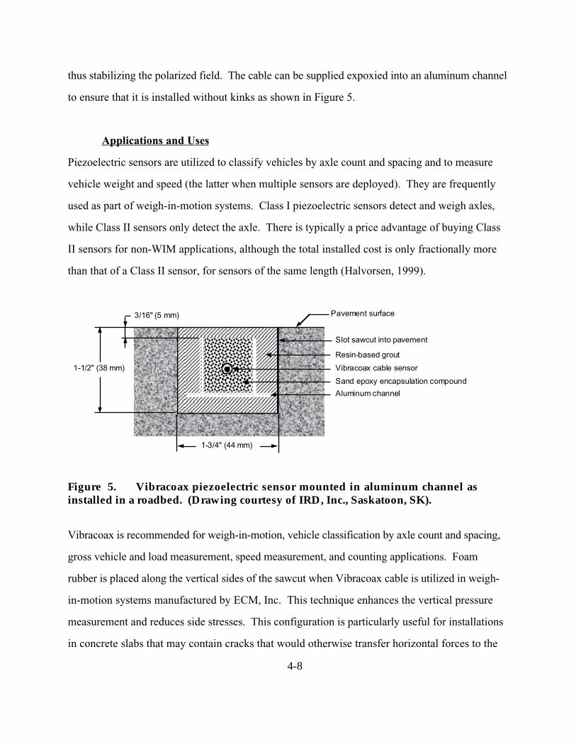
4-8
thus stabilizing the polarized field. The cable can be supplied expoxied into an aluminum channel
to ensure that it is installed without kinks as shown in Figure 5.
Applications and Uses
Piezoelectric sensors are utilized to classify vehicles by axle count and spacing and to measure
vehicle weight and speed (the latter when multiple sensors are deployed). They are frequently
used as part of weigh-in-motion systems. Class I piezoelectric sensors detect and weigh axles,
while Class II sensors only detect the axle. There is typically a price advantage of buying Class
II sensors for non-WIM applications, although the total installed cost is only fractionally more
than that of a Class II sensor, for sensors of the same length (Halvorsen, 1999).
Figure 5. Vibracoax piezoelectric sensor mounted in aluminum channel asinstalled in a roadbed. (Drawing courtesy of IRD, Inc., Saskatoon, SK).
Vibracoax is recommended for weigh-in-motion, vehicle classification by axle count and spacing,
gross vehicle and load measurement, speed measurement, and counting applications. Foam
rubber is placed along the vertical sides of the sawcut when Vibracoax cable is utilized in weigh-
in-motion systems manufactured by ECM, Inc. This technique enhances the vertical pressure
measurement and reduces side stresses. This configuration is particularly useful for installations
in concrete slabs that may contain cracks that would otherwise transfer horizontal forces to the
Aluminum channel
Resin-based grout
Slot sawcut into pavement
1-3/4" (44 mm)
3/16" (5 mm) Pavement surface
Vibracoax cable sensor
Sand epoxy encapsulation compound
1-1/2" (38 mm)

4-9
cable sensor. The sawcut and cable are sealed with fillers that match the mechanical properties of
the road surface to produce a slightly domed surface.
Other examples of piezoelectric sensors include the Roadtrax BL and the BLC sensors. The
Roadtrax piezoelectric sensor is manufactured with and without an aluminum channel for
permanent or temporary installation in the roadbed (Roadtrax, 1995-1996). It supports Class I
and Class II operations.
The BL (Brass LinguiniTM
) model is installed directly into the roadbed in a slot 0.75-in (19-mm)
wide by 0.75-in (19-mm) deep (typical). Polyurethane, epoxy, and acrylic grouts are available
for sealing the slot.
When the BLC aluminum channel model is installed, as depicted in Figure 6, the same epoxy is
used inside the channel to encapsulate the sensor and for installation in the road. This eliminates
or greatly reduces temperature coefficient effects.
1-1/4" (32 mm) typ Aluminum channel
EpoxySlot sawcut into pavement
1-1/2" (38 mm) typ
3/16" (5 mm) typ Pavement surface
Roadtrax piezoelectric sensor
Epoxy
0.795" (20 mm) typ
Figure 6. Roadtrax piezoelectric BLC sensor mounted in aluminum channel asinstalled in a roadbed (Roadtrax, 1995-1996).

4-10
Bonding Materials
A study by Fowler (Fowler, 1996) of current state practices for bonding piezoelectric sensors to
pavement revealed that the bond between the piezoelectric sensor and the pavement was lost
where rutting occurred. Several laboratory tests performed on the bonding material were found
more relevant than others in predicting field performance of bonding agents. The most beneficial
tests are listed in Table 3. Although all of these characteristics were critical, some were more
indicative of desired material behavior as indicated by their rank.
Table 3.Recommended tests for determining bonding ability of agents used with
piezoelectric sensors
Recommended Test Required Result Importance Ranka
Compressive strength
(ASTM C 116-90)
Approx. 7 MPa 1
Storage modulus (G )
component of the complex
shear modulus
(AASHTO TP5)
14 to 70 Mpa at 25oC,
decreases with increasing temperature
2
Gel time (ASTM C881) 5 to 15 min 3
Shrinkage (DuPont method) 1.0% expansion to 0.5% shrinkage 1
Vicat set time
(ASTM C 191-192)
Approx. 30 min 3
Viscosity (optional)
ASTM D 2393)
20 to 40 Pa-s 1
Flexural bond strength
(ASTM C 78-84)
Approx. 700 kPa to asphalt,
Approx. 2100 kPA to concrete,
at least 50% of failures in paving material
and away from the bond
2
Filed trial (ease of use) Acceptance by installation crew 3 a
3 most important, 1 least important.
Advantages
Piezoelectric sensors offer the unique advantage of being able to gather information on the tire
passing over the sensor, rather than on the passing of a vehicle. Piezoelectric sensors detect the
passing of the tire over the sensor, thus creating an analogue signal that is proportional to the
pressure exerted on the sensor. This unique ability of piezoelectric sensors allows them to

4-11
differentiate individual vehicles with extreme precision. In addition, on an installed cost basis,
they are only marginally more expensive than an inductive loop, but provide significantly more
information in the form of improved speed information, the ability to determine the classification
of the vehicle, and the capability to determine and monitor the weights of vehicles for WIM
systems.
Disadvantages
The drawbacks to the use of piezoelectric sensors are similar to those of inductive loop sensors
in that they include disruption of traffic for installation and repair and failures associated with
installations in poor road surfaces and use of substandard installation procedures. In many
instances multiple detectors are usually required to instrument a location. In addition, resurfacing
of roadways and utility repair can also create the need to reinstall these types of sensors. Also,
piezoelectric sensors have been known to be sensitive to pavement temperature and vehicle
speed.

MANUFACTURER AND VENDOR INFORMATION
Effective Date: 29 March 2000
Manufacturer name: Sales representative name(s):
Diamond Traffic. Guy Gibson Sr., Vice President
Address: Address:
P.O. Box 1455 P.O. Box 1455
Oakridge, OR 97463 Oakridge, OR 97463
Phone number: (541) 782-3903 Phone number:
Fax number: (541) 782-2053 Fax number:
e-mail address: [email protected] e-mail address: [email protected]
URL address: www.diamondtraffic.com URL address:
PRODUCT NAME/MODEL NUMBER: Phoenix Vehicle Classifier
FIRMWARE VERSION/CHIP NO.: 2.39
SOFTWARE VERSION NO.: Trafman 469
GENERAL DESCRIPTION OF EQUIPMENT: Time interval vehicle classifier and counter
utilizing loops, piezo, road tube, fiber optic, and radar
SENSOR TECHNOLOGY AND CONFIGURATION: Loops, piezo, road tube, fiber optic, radar
SENSOR INSTALLATION:
INSTALLATION TIME (Per Lane): Sensors cut into pavement can require 6-10 hours
INSTALLATION REQUIREMENTS:.
MAXIMUM NUMBER OF LANES MONITORED SIMULTANEOUSLY: 16 using loops for
count or 8 using loops and piezo for classification

PRODUCT CAPABILITIES/FUNCTIONS: Count, classify, vehicles, incident detection and
notification.
RECOMMENDED APPLICATIONS: 2 lane to multilane freeways for count and classification
POWER REQUIREMENTS (watts/amps): Range form 50 milliamps to 100 milliamps
POWER OPTIONS: 110 VAC, battery, or solar
CLASSIFICATION ALGORITHMS: FHWA 13, European
TELEMETRY: 300 to 19200. Optional 14.4K low power drew modem
COMPUTER REQUIREMENTS:
DATA OUTPUT: 28 print formats, spreadsheets
DATA OUTPUT FORMATS:
SUPPORTING DATA BASE MANAGEMENT SYSTEM: Mix of windows and DOS software,
NT compatible
EQUIPMENT AND INSTALLATION COSTS (One-lane and four-lane):One lane $1100 to $1500
Four lanes $1400 to $2000
STATES CURRENTLY USING THIS EQUIPMENT:
Country/State Contact name Telephone numberUSA/Idaho Brian Hagen (208) 334-8250
USA/Nevada Cecil Crandel (775) 888-7155
USA/Washington John Rosen (360) 753-6100
USA/Colorado Steve Plasten (303) 757-9467
USA/Nebraska Terry Guy (402) 479-4509
USA/Connecticut Erick Glover (860) 594-2088
USA/Wyoming (307) 777-4433

MANUFACTURER AND VENDOR INFORMATION
Effective Date: 2/29/00
Manufacturer name: Sales representative name(s):
Truvelo Manufacturers (Pty) Ltd. James E. Kelly
AVIAR inc
Address: P.O. Box 14183 Address: P.O. Box 162184
Lyttelton 0140 Austin, TX 78716
South Africa
Phone number: 011-27-11-314-1405 Phone number: (512) 295-5285
Fax number: 011-27-11-314-1409 Fax number: (512) 295-2603
e-mail address: [email protected] e-mail address: [email protected]
URL address: www.truvelo.co.za URL address: www.aviarinc.com
PRODUCT NAME/MODEL NUMBER: The Combi Speed/red Light Camera System
FIRMWARE VERSION/CHIP NO.: N/A
SOFTWARE VERSION NO.: N/A
GENERAL DESCRIPTION OF EQUIPMENT: Automatic speed and/or traffic light violation
recording system for portable and/or permanent installation in one compact unit.
Evidence of violation is shown on photograph.
SENSOR TECHNOLOGY AND CONFIGURATION: 3 or 4 piezo sensors for speed or 2
inductive loops/lane for presence at signalized intersection.
SENSOR INSTALLATION: Either surface mounted or cut into roadway surface
INSTALLATION TIME (Per Lane): Portable installation: 60 min. for 3 lanes
Permanent installation: 2 days
INSTALLATION REQUIREMENTS: N/A
MAXIMUM NUMBER OF LANES MONITORED SIMULTANEOUSLY: 3 lanes

PRODUCT CAPABILITIES/FUNCTIONS: Monitor traffic for speed violations or red light
violations.
RECOMMENDED APPLICATIONS: Speed and red light enforcement
POWER REQUIREMENTS (watts/amps):Portable: 12 volts D.C.
Permanent: Either 12 volts D.C. or 220-240 volts single phase A.C.
POWER OPTIONS: Either 12 volt battery or commercial source
CLASSIFICATION ALGORITHMS: N/A
TELEMETRY: N/A
COMPUTER REQUIREMENTS: Internal microprocessors
DATA OUTPUT: Photo evidence plus location code, time, date, speed, photo counter, traffic
counter, statistical data (lowest/highest speed, average speed, 85 percentile speed, vehicle speed
distribution)
DATA OUTPUT FORMATS: On photo or on instrument display
SUPPORTING DATA BASE MANAGEMENT SYSTEM: N/A
EQUIPMENT AND INSTALLATION COSTS (One-lane and four-lane):Contact Truvelo for cost information.
STATES CURRENTLY USING THIS EQUIPMENT:
Country/State Contact name Telephone numberUSA/Florida Chief Tony Sparks (941) 534-5034
Bartow Police Dept.
USA/Texas Walter Ragsdale (972) 238-4273
City of Richardson
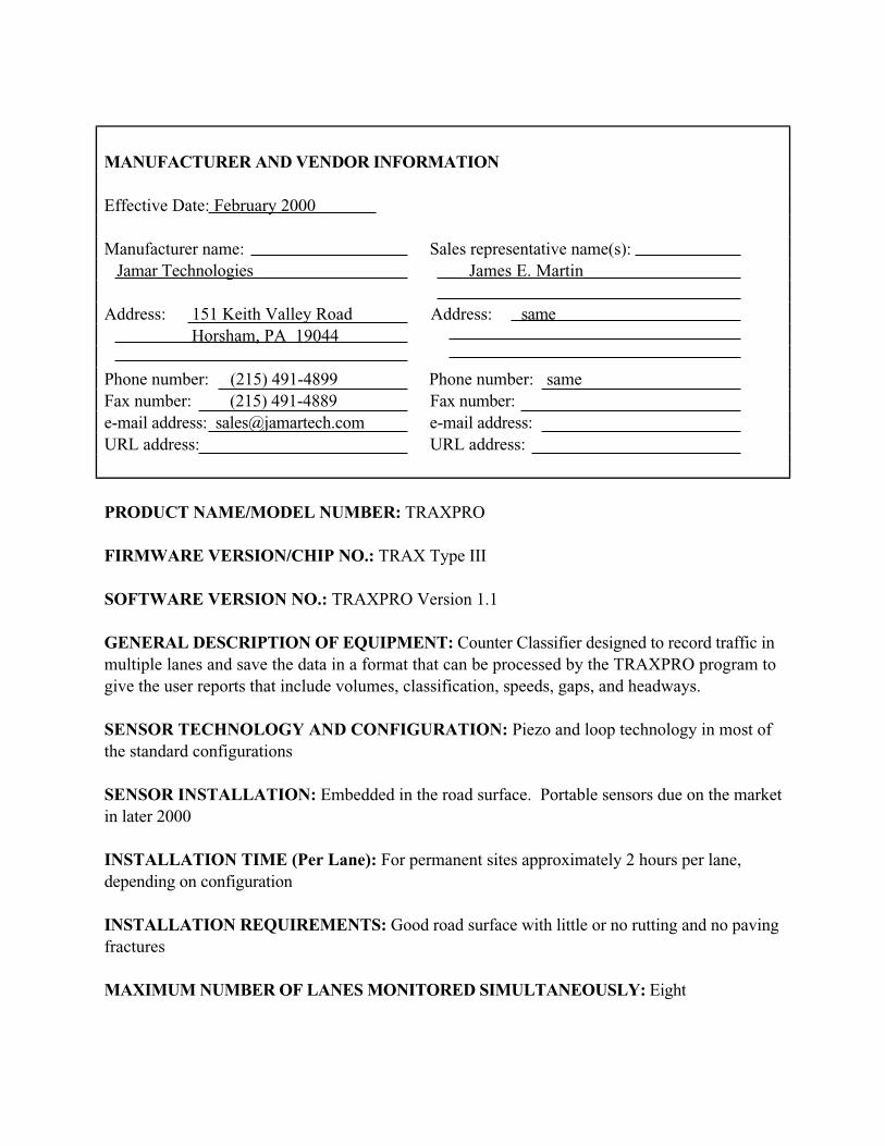
MANUFACTURER AND VENDOR INFORMATION
Effective Date: February 2000
Manufacturer name: Sales representative name(s):
Jamar Technologies James E. Martin
Address: 151 Keith Valley Road Address: same
Horsham, PA 19044
Phone number: (215) 491-4899 Phone number: same
Fax number: (215) 491-4889 Fax number:
e-mail address: [email protected] e-mail address:
URL address: URL address:
PRODUCT NAME/MODEL NUMBER: TRAXPRO
FIRMWARE VERSION/CHIP NO.: TRAX Type III
SOFTWARE VERSION NO.: TRAXPRO Version 1.1
GENERAL DESCRIPTION OF EQUIPMENT: Counter Classifier designed to record traffic in
multiple lanes and save the data in a format that can be processed by the TRAXPRO program to
give the user reports that include volumes, classification, speeds, gaps, and headways.
SENSOR TECHNOLOGY AND CONFIGURATION: Piezo and loop technology in most of
the standard configurations
SENSOR INSTALLATION: Embedded in the road surface. Portable sensors due on the market
in later 2000
INSTALLATION TIME (Per Lane): For permanent sites approximately 2 hours per lane,
depending on configuration
INSTALLATION REQUIREMENTS: Good road surface with little or no rutting and no paving
fractures
MAXIMUM NUMBER OF LANES MONITORED SIMULTANEOUSLY: Eight

PRODUCT CAPABILITIES/FUNCTIONS: Volume, speed, classifications, gaps and
headways.
RECOMMENDED APPLICATIONS: Any permanent or semi-permanent site
POWER REQUIREMENTS (watts/amps): 15 MA battery powered, solar option available.
A/C power optional
POWER OPTIONS: See above
CLASSIFICATION ALGORITHMS: FHWA and custom ones per your needs
TELEMETRY: Availability late 2000
COMPUTER REQUIREMENTS: Pentium
DATA OUTPUT: ASCII & Binary
DATA OUTPUT FORMATS: Standard
SUPPORTING DATA BASE MANAGEMENT SYSTEM: Processed data files may be
exported to Excel, Quattro-Pro, Lotus programs
EQUIPMENT AND INSTALLATION COSTS (One-lane and four-lane):One- lane — approximately $4,000.00 and four - lane — approximately $6,000.00
STATES CURRENTLY USING THIS EQUIPMENT:
Country/State Contact name Telephone numberUSA/Vermont Dave Gosselin (802) 828-2694

MANUFACTURER AND VENDOR INFORMATION
Effective Date:March 22, 2000
Manufacturer name: International Road Sales representative name(s): Rod Klashinsky
Dynamics, Inc.
Address: 702 43rd
Street East Address:
Saskatoon SK, S7K 3T9 Canada
Phone number: 306-653-6600 Phone number:
Fax number: 306-242-5599 Fax number:
e-mail address: [email protected] e-mail address:
URL address: www.irdinc.com URL address:
PRODUCT NAME/MODEL NUMBER: IRD Truck Advisory Safety Systems
FIRMWARE VERSION/CHIP NO.: NA
SOFTWARE VERSION NO.: NA
GENERAL DESCRIPTION OF EQUIPMENT: The IRD Truck Advisory Safety Systems
determine truck speed, weight, height and classification (based on axle configuration). Using this
information the systems are capable of displaying messages on a roadwide sign to instruct drivers
to slow down prior to a sharp turn in the road or to proceed at a recommended speed prior to a
steep decline in the road.
SENSOR TECHNOLOGY AND CONFIGURATION: The system typically uses an
inductive loop-Class I piezo sensor- Class I piezo sensor-loop configuration.
SENSOR INSTALLATION: Sensors are saw-cut and grouted into the roadway. Sensor leads
are run through conduit to a roadside cabinet.
INSTALLATION TIME (Per Lane): Depending on the application, installation of the in-road
sensors, signs and associated electronics may take from 2-weeks to a month.
INSTALLATION REQUIREMENTS: Please see attached product information for details.

MAXIMUM NUMBER OF LANES MONITORED SIMULTANEOUSLY: Typically only a
single lane of in-road equipment is required for the IRD Safety Systems.
PRODUCT CAPABILITIES/FUNCTIONS: Truck Rollover Advisory, Downhill Truck Speed
Advisory, and Runaway Truck Traffic signal control.
RECOMMENDED APPLICATIONS: Truck Rollover Advisory, downhill Truck Speed
Advisory, and runaway Truck Traffic Signal control.
POWER REQUIREMENTS (watts/amps): 2.5 Amps/35 Watts (For the WIM electronics)
POWER OPTIONS: 100-240 VAC, 50-60 Hz. (For the WIM electronics).
CLASSIFICATION ALGORITHMS: Vehicles can be classified based on axle weights, axle
spacings, axle groupings and GVW.
TELEMETRY: Terminal software and standard telephone line with modem are required.
COMPUTER REQUIREMENTS: Pentium II or better, 400 MHz min., 32 Mb RAM min.,
Expansion slots 1 ISA, 3 PCI, 1 ISA/PCI.
DATA OUTPUT: Individual vehicle and vehicle summary data are stored on the WIM computer
which can be retrieved through a modem. Individual vehicle data can also be sent to an RS 232
port on the WIM in real-time.
DATA OUTPUT FORMATS: The vehicle information is stored on disk files in a compressed
format developed by IRD. Software is available to convert the data to CSV (Comma, Sparated
Value) file. Several industry standard formats are available for the WIM vehicle data transmitted
through the RS 232 port.
SUPPORTING DATA BASE MANAGEMENT SYSTEM: Report generation software is
available from IRD that reads the compressed vehicle data files directly. Raw data can also be
exported to a file which can be read by any database system.
EQUIPMENT AND INSTALLATION COSTS (One-lane and four-lane):1-lane: $ 150,000 US and 4-lane: $ 300,000 US
STATES CURRENTLY USING THIS EQUIPMENT: (Use back of page if needed)Country/State Contact name Telephone numberUSA/Pennsylvania (PennDot) Jim Garling (717) 787-3656
USA/Colorado (CDOT) Dave Judy (303) 512-5813

4-12
Magnetic Sensors
Principles of Operation
Magnetic sensors are passive devices that indicate the presence of a metallic object by detecting
the perturbation (known as a magnetic anomaly) in the Earth s magnetic field created by the
object. Figure 7a shows the magnetic anomaly created by the magnetic dipoles, i.e., energy fields,
on a steel vehicle when it enters the magnetometer s detection zone (Kell, 1990; Lenz, 1993; and
Sampey, 1999). The upper part of Figure 7b indicates how the vector addition of the dipole
magnetic field to the quiescent Earth s magnetic field produces the magnetic anomaly. The lower
portion of the figure depicts several dipoles on a vehicle and their effect on compass readings and
sensor output.
Figure 8 illustrates the distortion induced in the Earth s magnetic field as a vehicle enters and
passes through the detection zone of a magnetic sensor. Figure 8a depicts the magnetic field as
the vehicle approaches the sensor. Figure 8b shows the field lines of flux as the vehicle begins to
pass through the sensor s detection zone. Figure 8c describes the lines of flux when the vehicle is
over the sensor.
Application and Uses
Two types of magnetic field sensors are used for traffic flow parameter measurement. The first
type, the two-axis fluxgate magnetometer, detects changes in the vertical and horizontal
components of the Earth s magnetic field produced by a ferrous metal vehicle. The two-axis
fluxgate magnetometer contains a primary winding and two secondary sense windings on a
bobbin surrounding a high permeability soft magnetic material core. In response to the magnetic
field anomaly, i.e., the magnetic signature of a vehicle, the magnetometer s electronics circuitry
measures the output voltage generated by the secondary windings. The vehicle detection
criterion is for the voltage to exceed a predetermined threshold. In the presence mode of

4-13
operation, the detection output is maintained until the vehicle leaves the detection zone.
Examples of sensors based on two-axis fluxgate magnetometers are shown in Figure 9.
The second type of magnetic field sensor is the magnetic detector, more properly referred to as
an induction or search coil magnetometer. It detects the vehicle signature by measuring the
change in the magnetic lines of flux caused by the change in field values produced by a moving
ferrous metal vehicle. These devices contain a single coil winding around a permeable magnetic
material rod core. Like the fluxgate magnetometer, magnetic detectors generate a voltage when a
ferromagnetic object perturbs the Earth s magnetic field. However, most magnetic detectors
cannot detect stopped vehicles, since they require a vehicle to be moving or otherwise changing
its signature characteristics with respect to time. Examples of sensors that use the induction
magnetometer principle are shown in Figure 10.
Advantages
The two-axis fluxgate magnetometer is less susceptible than loops to stresses of traffic. Also
some models of the two-axis fluxgate magnetometer transmit data over wireless RF link.
The induction or search coil magnetometer is also less susceptible than loops to stresses of
traffic. The induction magnetometer can be used where loops are not feasible (e.g., bridge decks)
and some models can be installed under the roadway without the need for pavement cuts.
Disadvantages
Installation of magnetic sensors requires pavement cut or tunneling under the roadway and thus
requires lane closure during installation. Magnetic detectors cannot generally detect stopped
vehicles. Also, some models have small detection zones.

4-14
(a) Magnetic anomaly induced in the Earth s magnetic field by a magnetic dipole
(b) Perturbation of Earth s magnetic field by a ferrous metal vehicle.(Drawing courtesy of Nu-Metrics, Vanderbilt, PA).
Figure 7. Magnetic anomaly in the Earth’s magnetic field induced by magneticdipoles in a ferrous metal vehicle.
Earth’s magnetic fieldin absence of metal vehicle
Magnetic dipole produced by ferrous materials
Resultant magnetic anomalyin Earth’s magnetic field

4-15
Figure 8. Distortion of Earth’s magnetic field created as a vehicle enters andpasses through the detection zone of a magnetic sensor. (Drawing courtesy of Nu-Metrics, Vanderbilt, PA).

4-16
SPVD magnetometer system. (Photographcourtesy of Midian Electronics, Tucson, AZ).
Figure 9. Two-axis fluxgate magnetometer sensors.
Figure 10. Induction magnetometer sensors.
Groundhog magnetometer. (Photographcourtesy of Nu-Metrics, Uniontown, PA).
Model 701 microloop probe.(Photograph courtesy of 3MCompany, St. Paul, MN)
231E Detector Probe. (Photographcourtesy of Safetran Traffic Systems,Colorado Springs, Co).

MANUFACTURER AND VENDOR INFORMATION
Effective Date: 2/24/00
Manufacturer name: 3M Sales representative name(s):
Intelligent Transportation Systems D. Henderson/Sales Mgr.
Address: 3M Center, Bldg 225-4N-14 Address: 3M ITS
St. Paul, MN 55144-1000 same
Phone number: (800) 328-7098 Phone number:
Fax number: Fax number:
e-mail address: e-mail address:
URL address: www.mmm.com/ITS URL address:
PRODUCT NAME/MODEL NUMBER: Canoga Vehicle Detection System Model 702 Non-
invasive micro loop
FIRMWARE VERSION/CHIP NO.: N/A
SOFTWARE VERSION NO.: N/A
GENERAL DESCRIPTION OF EQUIPMENT: A small cylindrical sensor, a carrier system to be
installed in 3 conduit under the road surface.
SENSOR TECHNOLOGY AND CONFIGURATION: Magnetic flux gate
SENSOR INSTALLATION: Soil piercing to install conduit
INSTALLATION TIME (Per Lane): Various
INSTALLATION REQUIREMENTS: Soil piercing to install conduit
MAXIMUM NUMBER OF LANES MONITORED SIMULTANEOUSLY: Unlimited
PRODUCT CAPABILITIES/FUNCTIONS: Various

RECOMMENDED APPLICATIONS: All presence and passage
POWER REQUIREMENTS (watts/amps): N/A
POWER OPTIONS: N/A
CLASSIFICATION ALGORITHMS: N/A
TELEMETRY: N/A
COMPUTER REQUIREMENTS: N/A
DATA OUTPUT: N/A
DATA OUTPUT FORMATS: N/A
SUPPORTING DATA BASE MANAGEMENT SYSTEM: N/A
EQUIPMENT AND INSTALLATION COSTS (One-lane and four-lane): N/A
STATES CURRENTLY USING THIS EQUIPMENT:
Country/State Contact name Telephone number
CONTACT 3M FOR CURRENT LIST OF REFERENCES.

MANUFACTURER AND VENDOR INFORMATION
Effective Date:
Manufacturer name: Sales representative name(s):
Midian Electronics, Inc. Michael Soulliard
Address: Address:
2302 E. 22nd
St.
Tucson, AZ 85713
Phone number: (520) 884-7981 Phone number:
Fax number: (520) 884-0422 Fax number:
e-mail address: [email protected] e-mail address:
URL address: www.midelec.com URL address:
PRODUCT NAME/MODEL NUMBER: The Road Runner Systems (SPVD-1, SPVDREC)
FIRMWARE VERSION/CHIP NO.: N/A
SOFTWARE VERSION NO.: N/A
GENERAL DESCRIPTION OF EQUIPMENT: Wireless Vehicle Detector
SENSOR TECHNOLOGY AND CONFIGURATION: Dual Axis Flux Gate Magnetometer
SENSOR INSTALLATION: Installed in the roadway using 6 core drill bit approximately 12 in
depth.
INSTALLATION TIME (Per Lane): 30 minutes per lane and 45 minutes at the traffic control
cabinet.
INSTALLATION REQUIREMENTS: See sensor installation above.
MAXIMUM NUMBER OF LANES MONITORED SIMULTANEOUSLY: One lane per detector.
PRODUCT CAPABILITIES/FUNCTIONS: Detect vehicles for traffic counting or presence
detection.

RECOMMENDED APPLICATIONS: Left-turn lane detection, advanced detection, through lane
detection, counting, side street detection.
POWER REQUIREMENTS (watts/amps): SPVD-1 12v 15Ah battery
SPVDREC — 12 V 100 mA
POWER OPTIONS:
CLASSIFICATION ALGORITHMS:
TELEMETRY: 47 MHz — Part 90 FCC Rules & Regulations
COMPUTER REQUIREMENTS: N/A
DATA OUTPUT: Optoisolator Logic low input to controller
DATA OUTPUT FORMATS: N/A
SUPPORTING DATA BASE MANAGEMENT SYSTEM: N/A
EQUIPMENT AND INSTALLATION COSTS (One-lane and four-lane): $600 per lane plus
receiver cost (varies depending on requirements)
STATES CURRENTLY USING THIS EQUIPMENT:
Country/State Contact name Telephone numberUSA/Washington Brian Martin (206) 440-4447
USA/Florida-SABCO Randy Fortner (321) 784-1100
USA/Conn- Signal Service Wayne Halcombe (860) 289-8033

MANUFACTURER AND VENDOR INFORMATION
Effective Date: 2/24/00
Manufacturer name: 3M Sales representative name(s):
Intelligent Transportation Systems D. Henderson/Sales Mgr.
Address: 3M Center, Bldg 225-4N-14 Address: 3M ITS
St. Paul, MN 55144-1000 same
Phone number: (800) 328-7098 Phone number:
Fax number: Fax number:
e-mail address: e-mail address:
URL address: www.mmm.com/ITS URL address:
PRODUCT NAME/MODEL NUMBER: Canoga Vehicle Detection System Model 701 Microloop
FIRMWARE VERSION/CHIP NO.: N/A
SOFTWARE VERSION NO.: N/A
GENERAL DESCRIPTION OF EQUIPMENT: A small cylindrical sensor, to detect passage of
vehicle. Installed in bored hole in pavement
SENSOR TECHNOLOGY AND CONFIGURATION: Induction magnetometer
SENSOR INSTALLATION: Bored hole/saw slot in pavement
INSTALLATION TIME (Per Lane): Various
INSTALLATION REQUIREMENTS: Same as wire loop
MAXIMUM NUMBER OF LANES MONITORED SIMULTANEOUSLY: Unlimited
PRODUCT CAPABILITIES/FUNCTIONS: Various
RECOMMENDED APPLICATIONS: All presence and passage

POWER REQUIREMENTS (watts/amps): N/A
POWER OPTIONS: N/A
CLASSIFICATION ALGORITHMS: N/A
TELEMETRY: N/A
COMPUTER REQUIREMENTS: N/A
DATA OUTPUT: N/A
DATA OUTPUT FORMATS: N/A
SUPPORTING DATA BASE MANAGEMENT SYSTEM: N/A
EQUIPMENT AND INSTALLATION COSTS (One-lane and four-lane): N/A
STATES CURRENTLY USING THIS EQUIPMENT:
Country/State Contact name Telephone number
CONTACT 3M FOR CURRENT LIST OF REFERENCES.

4-17
Weigh-in-Motion (WIM)
Highway Weigh-in-Motion (WIM) systems are capable of estimating the gross vehicle weight of
a vehicle as well as the portion of this weight that is carried by each wheel assembly (half-axle
with one or more tires), axle, and axle group on the vehicle (ASTM E1318-94, 1994). WIM data
are used by highway planners and designers, as well as by enforcement agencies (e.g. Department
of Public Safety, etc.).
Application and Uses
WIM systems increase the capacity of weigh stations and are often utilized when heavy truck
traffic volumes cannot otherwise be accommodated. WIM systems provide highway planners
and designers with time and date of traffic volume, speed, vehicle classification based on number
and spacing of axles, and the equivalent single axle loading (ESAL) that heavy vehicles place on
pavements and bridges. The heavy truck axle load data are used by motor vehicle enforcement
officers to plan enforcement activities (McCall & Vodrazka, 2000). Software is frequently
provided by the manufacturers to aid in system calibration and data analysis. The categories of
WIM systems are listed in Table 4 along with the corresponding data each provide (ASTM
E1318-94, 1994). Table 5 gives the functional performance requirements of WIM systems as
defined by ASTM (ASTM E1318-94, 1994). Some states may impose more strict requirements
such as those in Table 6 (McCall & Vodrazka, 2000).
The accuracy of WIM systems is a function of four principal factors:
• Vehicle dynamics;
• Pavement integrity, composition, and design;
• Variance inherent in the WIM system; and
• Calibration.

4-18
Vehicle dynamics are dependent on road surface roughness, type of vehicle suspension, vehicle
dynamic balance, vehicle weight, vehicle speed, driver maneuvering, etc. Although most agencies
attempt to install WIM systems in good pavement, unexpected deterioration or structural
anomalies sometimes occur. For instance, WIM measurements worsen when asphalt pavements
soften in hot weather and long concrete sections rock along a central axis when a heavy truck
passes over the end of the section. The inherent variance of the WIM system is a function of the
technology utilized in the system to measure axle weight.
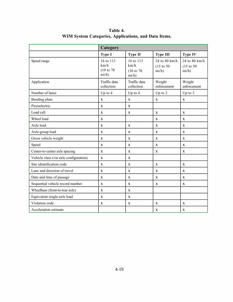
4-19
Table 4.WIM System Categories, Applications, and Data Items.
CategoryType I Type II Type III Type IV
Speed range 16 to 113
km/h
(10 to 70
mi/h)
16 to 113
km/h
(10 to 70
mi/h)
24 to 80 km/h
(15 to 50
mi/h)
24 to 80 km/h
(15 to 50
mi/h)
Application Traffic data
collection
Traffic data
collection
Weight
enforcement
Weight
enforcement
Number of lanes Up to 4 Up to 4 Up to 2 Up to 2
Bending plate X X X X
Piezoelectric X X
Load cell X X X X
Wheel load X X X
Axle load X X X X
Axle-group load X X X X
Gross vehicle weight X X X X
Speed X X X X
Center-to-center axle spacing X X X X
Vehicle class (via axle configuration) X X
Site identification code X X X X
Lane and direction of travel X X X X
Date and time of passage X X X X
Sequential vehicle record number X X X X
Wheelbase (front-to-rear axle) X X
Equivalent single-axle load X X
Violation code X X X X
Acceleration estimate X X

4-20
Table 5.ASTM performance requirements for WIM systems
Tolerance for 95% Probability of ConformityFunction Type IV
Type I Type II Type IIIValue ≥ lb (kg)a
+ lb (kg)
Wheel load + 25% + 20% 5,000 (2,300) 250 (100)
Axle load + 20% + 30% + 15% 12,000 (5,400) 500 (200)
Axle load group load + 25% + 20% + 10% 25,000 (11,300) 1,200 (500)
Gross vehicle weight + 10% + 15% + 6% 60,000 (27,200) 2,500 (1,100)
Speed + 1 mi/h ( + 2 km/h)
Axle spacing + 0.5 ft ( + 150 mm)
aLower values are not usually a concern in enforcement.
Source: Standard Specification for Highway Weigh-in-Motion (WIM) Systems with User Requirements and TestMethod, Designation E 1318-94, 2000 Annual Book of ASTM Standards, Vol. 04.03, West Conshohocken, PA:
ASTM.
Table 6.California Department of Transportation (Caltrans) performance requirements
for WIM systemsa
Parameter Mean Standard Deviation
Vehicle weight
Single axle + 5 % 8%
Tandem axle + 5 % 6%
Gross weight + 5 % 5%
Axle spacing + 150 mm (6 in) 300 mm (12 in)
Vehicle length + 300 mm (12 in) 460 mm (18 in)
Vehicle speed + 1.6 km/h (1 mi/h) 3.2 km/h (2 mi/h)
a Source: McCall, W. and W.C. Vodrazka Jr., States’ Successful Practices Weigh-In-MotionHandbook, Center for Transportation Research and Education (CTRE), Iowa State University,
Dec. 15, 1997, http://www.ctre.iastate.edu/research/wim_pdf/ index.htm.

4-21
Table 7 gives typical values for the inherent variance component of the system accuracy (for a + 1
standard deviation confidence interval) for piezoelectric, bending plate, and single load cell
systems. The table shows that it is common for WIM systems to be less accurate when
weighing individual axle groups than when measuring gross vehicle weight. The effect of vehicle
speed on total system accuracy is accounted for later in Table 8. Time out factors are sometimes
programmed into WIM systems to assist in separating the weight of one vehicle from another.
Table 7.Inherent variance component of system accuracy a
(1 standard deviation confidence interval)
WIM SystemTechnology
Axle GroupWIM Accuracy (%)
GVWb
WIM Accuracy(%)
Piezoelectric cablec
12 10
Bending plate 3 2
Single load cell 2 1a Source: Bergan, A.T., C.F. Berthelot, and B. Taylor, Effect of Weigh in Motion Accuracy on
Weight Enforcement Accuracy, Proc. of 7th Annual Meeting, ITS-America, Washington, D.C.,
1997 and IRD Bending Plate and Load Cell Weigh-in Motion Scales Technical Specifications,
Aug. 1997 and Jan. 1998.b
Gross vehicle weightc
By comparison, the Kistler piezoelectric quartz sensor specification for wheel load measurement
accuracy is approx. + 3 percent.
Calibration ensures that the estimation of static weight by the WIM system closely
approximates the true static weight. Calibration accounts for site-specific effects such as
pavement temperature, vehicle speed, and pavement condition. Calibration procedures may
include an acceptance testing phase and a recalibration phase.
The acceptance testing phase used by Caltrans and reported in the State s Successful Practices
Weigh-in-Motion Handbook (McCall & Vodrazka, 2000) has three stages: system component
operation verification, initial calibration process, and a 72-h continuous operation verification.

4-22
• System component testing verifies the transmission of signals by the roadway sensors to
the on-site controller and the conversion of the signals into the desired WIM data.
• Initial calibration consists of comparing data obtained when one or more trucks passes over
the WIM sensors with measurements taken on a static scale. Several runs are made to
measure weight and axle spacing in each lane equipped with WIM sensors at speeds that
encompass the expected operational range. These data are utilized to compute the WIM
weight factors that convert the dynamic measurements into static weights. The test
vehicles make additional runs at each speed to verify the weight factor values. Weight
factors can be adjusted to account for seasonal variations, changes in pavement condition,
and unique vehicles.
• The 72-h calibration monitors WIM system operation to ensure continuous functioning
within the required specifications. When this phase is completed, the system is ready for
online operation.
The recalibration phase occurs throughout the design life of the WIM site. Weight factors are
adjusted or repairs made to the system when problems are identified during regularly scheduled
data reviews.
The four technologies used in WIM system weight measurement are bending plate, piezoelectric,
load cell, and capacitance mat. Each is discussed in the following sections.
Bending Plate
Principles of Operation
Bending plate WIM systems utilize plates with strain gauges bonded to the underside. As a
vehicle passes over the bending plate, as illustrated in Figure 11, the system records the strain

4-23
measured by the strain gauges and calculates the dynamic load. The static load is estimated using
the measured dynamic load and calibration parameters. The calibration parameters account for
factors, such as vehicle speed and pavement/ suspension dynamics, that influence estimates of
the static weight.
The accuracy of bending plate WIM systems can be expressed as a function of the vehicle speed
traversed over the plates, assuming the system is installed in a sound road structure and subject
to normal traffic conditions. The accuracy specifications in Table 8 apply to bending plate scales
manufactured by IRD. They are based on a minimum sample of 50 vehicles loaded to within
75% of the legal allowable limit. Vehicles that traverse the scale with more than a 10% speed
variation, live loads, or liquid loads are not permitted in the sample.

4-24
Table 8.Accuracy specifications for bending plate and load cell WIM scalesa
(1 standard deviation confidence interval)
Speed Application Load type Bending PlateAccuracy
Load CellAccuracyb
2 to 10 mi/h (3.2 to 16 km/h) Low speed/slow roll just prior
to static scalesSingle axle
Tandem axle
Gross weight
+ 3% of applied
+ 3% of applied
+ 2% of applied
+ 2% of applied
+ 1.5% of applied
+ 1% of applied
11 to 25 mi/h (18 to 40 km/h) Low speed ramp Single axle
Tandem axle
Gross weight
+ 4% of applied
+ 4% of applied
+ 3% of applied
+ 4% of applied
+ 3% of applied
+ 2% of applied
26 to 45 mi/h (42 to 72 km/h) Medium speed ramp Single axle
Tandem axle
Gross weight
+ 6% of applied
+ 6% of applied
+ 4% of applied
+ 5% of applied
+ 4% of applied
+ 3% of applied
46 and above mi/h
(74 and above km/h)
High speed ramp or mainline Single axle
Tandem axle
Gross weight
+ 8% of applied
+ 8% of applied
+ 5% of applied
+ 6% of applied
+ 5% of applied
+ 4% of applied
aFrom IRD Bending Plate and Load Cell Weigh-in Motion Scales Technical Specifications
bNormally single load cell scales are calibrated for one of the speed ranges. If site conditions require more than one speed range, the
system is calibrated for the range agreed to by the vendor and user.

4-25
Figure 11. Bending plate sensor. (Photographs courtesy of IRD, Inc., Saskatoon,SK).
Bending plate WIM systems contain either one or two scales and two ILDs. A typical bending
plate (or load cell) installation is shown in Figure 12. The scale is placed in the travel lane
perpendicular to the direction of travel. When two scales are used in one lane, one scale is placed
in each wheelpath of the traffic lane so that the left and right wheels are weighed individually.
The pair of scales is placed in the lane side-by-side or staggered by 5 m (16 ft). Bending plate
systems with one scale in the right or left wheelpath are usually used in low volume lanes. The
inductive loops are placed upstream and downstream of the scales. The upstream loop detects
vehicles and alerts the system to an approaching vehicle. The downstream loop determines
vehicle speed based on the time it takes the vehicle to traverse the distance between the loops.
Advantages
Bending plate WIM systems can be used for traffic data collection as well as for weight
enforcement purposes. The accuracy of these systems is higher than piezoelectric systems and
their cost is lower than load cell systems. Bending plate WIM systems do not require complete
replacement of the sensor but only refurbishing after 5 years.

4-26
Traffic FlowDirection
Loop 2
Loop 1
WIM Scale
Axle Sensor
Shoulder
4
6
57
3
1
2
Notes
1. Cabinet and base2. 1-in to 2-in conduit for scale leads in a
6-in wide by 6-in deep excavation3. Junction box4. Drill through shoulder for 1-in conduit5. 3/8-in sawcut for loop wire home run;
twist 3 turns per foot6. 3/8-in sawcut for axle sensor leads7. 2-in PVC drain
Power andtelephone
Figure 12. Bending plate or load cell WIM system (typical).
Disadvantages
Bending plate WIM systems are not as accurate as load cell systems and are considerably more
expensive than piezoelectric systems.
Piezoelectric
Principles of Operation
Piezoelectric WIM systems contain one or more piezoelectric sensors that detect a change in
voltage caused by pressure exerted on the sensor by an axle and thereby measure the axle s
weight. As a vehicle passes over the piezoelectric sensor, the system records the sensor output
voltage and calculates the dynamic load. As with bending plate systems, the dynamic load
provides an estimate of the static load when the WIM system is properly calibrated.

4-27
The typical piezoelectric WIM system consists of at least one piezoelectric sensor and two
ILDs. The piezoelectric sensor is placed in the travel lane perpendicular to the travel direction.
The inductive loops are placed upstream and downstream of the piezoelectric sensor. The
upstream loop detects vehicles and alerts the system to an approaching vehicle. The downstream
loop provides data to determine vehicle speed and axle spacing based on the time it takes the
vehicle to traverse the distance between the loops. Figure 13 shows a full-lane width
piezoelectric WIM system installation. In this example, two piezoelectric sensors are utilized on
either side of the downstream loop.
Cabinet
PVC conduitbelow ground
WIM strip,full-length,2 places
Inductiveloops (2)
Road shoulder
Traffic flowdirections
Figure 13. WIM installation with full-length piezoelectric sensors.
An emerging technology in piezoelectric WIM sensors is the LINEAS quartz sensors
manufactured by Kistler. Piezoelectric LINEAS quartz sensors manufactured by Kistler contain a
number of quartz crystal sensing elements mounted along the centerline of an aluminum core as
shown in Figure 14 (Kistler, 1997 & Caldera, 1996). The sensor is installed in a slot cut into the
road surface and is grouted with a proprietary compound of epoxy and silica sand. The elastic
and thermal properties of the compound closely match those of road surfaces. The sensor is
isolated from side forces by an elastic material to help eliminate errors caused by a volume effect.
The load bearing pad composed of a mixture of quartz sand and epoxy can be ground even with
the road surface.

4-28
Load bearing pad
Aluminum profile
Quartz sensing piezoelectric element
Elastic material
Figure 14. LINEAS quartz sensor (Drawing courtesy of Kistler Instruments AGWinterthur, Switzerland).
Advantages
Typical piezoelectric WIM systems are among the least expensive systems in use today in terms
of initial capital costs and life cycle maintenance costs. Piezoelectric WIM systems can be used
at higher speed ranges (10 to 70 mph) than other WIM systems. Piezoelectric WIM systems can
be used to monitor up to four lanes.
Quartz sensors do not generally age or fatigue. Temperature effects are negligible as the
temperature coefficient of quartz is approximately —0.02 %/K. Since quartz crystals have no
pyroelectric effect, rapid changes in temperature do not cause a drift in output signal. Wheel load
measurements are to within + 3 percent irrespective of the vehicle speed and position of the wheel
along the sensor. The accuracy of these sensors makes them performance and cost competitive
with the load cell WIM systems discussed in the next section.
Disadvantages
Typical piezoelectric systems (not quartz) are less accurate than load cell and bending plate
WIM systems. Also, as discussed previously, piezoelectric sensors may be sensitive to
temperature and speed variations. Piezoelectric sensors for WIM systems must be replaced at
least once every 3 years.

4-29
Load Cell
Principles of Operation
A typical load cell WIM system includes a single load cell, at least one ILD, and one axle sensor.
The load cell has two inline scales that operate independently. Off-scale sensors are integrated
into the scale assembly to sense any vehicles that are not on the weighing surface. The single
load cell system manufactured by IRD contains torsion bars within the WIM system frame that
transmit all forces to the load cell. This load cell has a small amount of hydraulic fluid that causes
a pressure transducer to relay weight information to roadside data analysis equipment. Load cells
are durable and among the most accurate WIM systems as indicated in Table 4.
The load cell is placed in the travel lane perpendicular to the direction of travel. The inductive
loop is placed upstream of the load cell to detect vehicles and alert the system of an approaching
vehicle. If a second inductive loop is used, it is placed downstream of the load cell to determine
axle spacing and vehicle speed. The axle sensor can utilize piezoelectric technology or technology
based on the change of sensor resistance with pressure.
Advantages
The load cell system is the most accurate WIM system available. Therefore, the load cell WIM
system can be utilized for traffic data collection as well as for weight enforcement purposes.
Disadvantages
The load cell is one of the most expensive WIM systems available today, in terms of initial
capital costs and life cycle maintenance costs. Also, the load cell WIM system requires a
complete replacement of the weighing mechanism after 5 years.

4-30
Capacitance Mat
Principles of Operation
A capacitance mat consists of a sandwich of metal steel sheets and dielectric material. In one
configuration, displayed in Figure 15, a stainless steel sheet is surrounded by polyurethane
dielectric material on either side. The outer surfaces of the polyurethane layers are enclosed by
other stainless steel sheets. An a.c. voltage is applied across the sandwich of materials. When a
vehicle passes over the mat, the spacing between the plates decreases and causes the capacitance
to increase. This changes the resonant frequency of the electrical circuit of which the capacitance
mat is a part. The resonant frequency, measured by the data analysis and recording equipment, is
thus proportional to the axle weight. Capacitance mats are also manufactured utilizing aluminum
plates separated by a grid of insulating material and air as the dielectric.
Figure 15. Capacitance mat sensor connected to data analysis equipment.(Photograph courtesy of LoadoMeter, Corp., Baltimore, MD).

4-31
Advantages
Capacitance mat sensors can be used for portable as well as permanent WIM applications.
These systems can monitor up to four lanes simultaneously.
Disadvantages
Capacitance mat WIM systems are not as accurate as load cell and bending plate WIM systems
for estimating weights. Also, the equipment and installation costs of these type of systems,
whether portable or permanent, are similar to the load cell WIM system costs, which are among
the most expensive WIM systems available.
Weigh-in-Motion System Costs
WIM system costs may be expressed in terms of the life cycle cost consisting of initial capital
cost (in-road WIM equipment, installation labor and materials, initial calibration, and traffic
control) and life cycle maintenance costs (labor and materials, traffic control, and system
recalibration). Table 9 contains budgetary initial capital costs for piezoelectric, bending plate,
and load cell technologies assuming typical road, traffic, and weather conditions. These costs
may vary from manufacturer to manufacturer and with sensor model. Roadside cabinets, WIM
electronics, power and communication connections, etc. are not included as these are common to
all the technologies.
The life cycle maintenance costs vary due to differences in traffic volumes and truck weights,
weather, original installation procedures, roadbed condition, onsite quality control, etc. Table 10
presents WIM system life cycle maintenance and repair costs averaged over North American
installations. They assume that annual routine maintenance (e.g., road inspection and crack
filling) is performed on the roadbed surrounding the WIM system. Piezoelectric sensors are
assumed to require replacing every 3 years, bending plates refurbishing every 5 years, and single
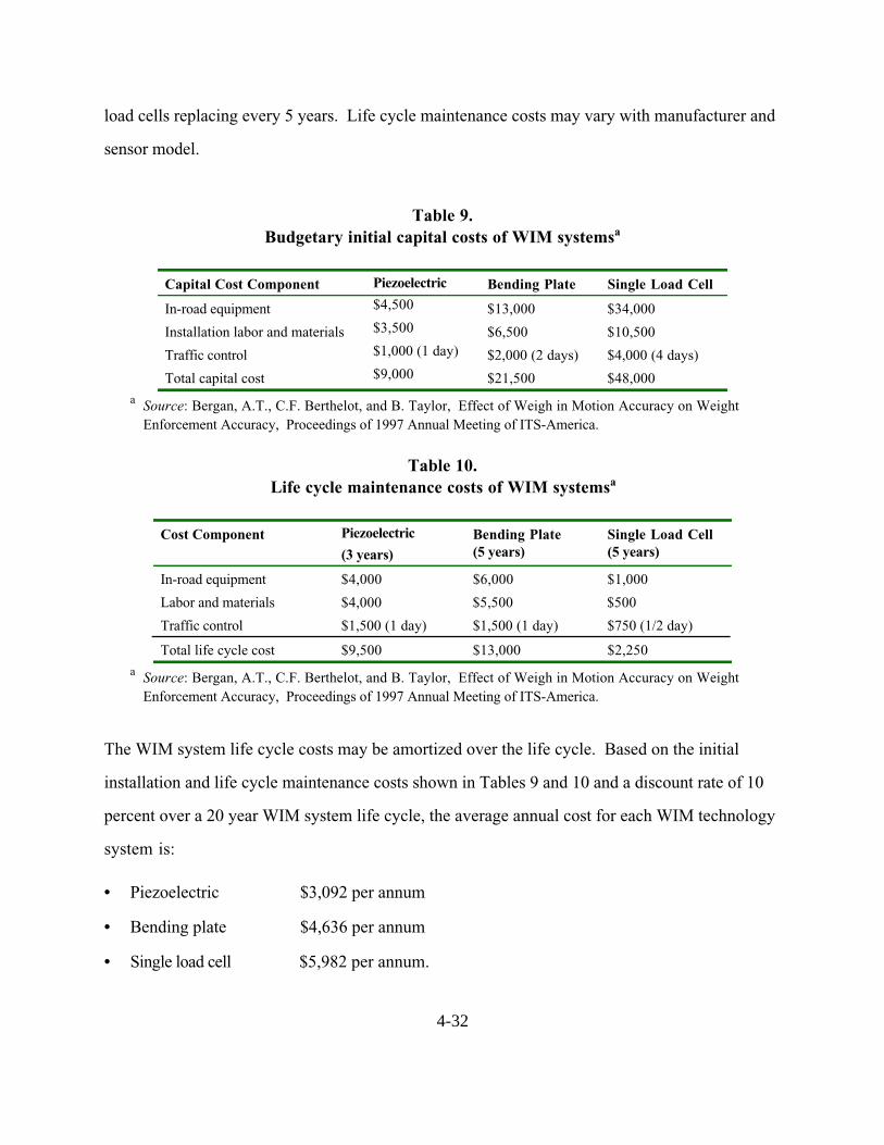
4-32
load cells replacing every 5 years. Life cycle maintenance costs may vary with manufacturer and
sensor model.
Table 9.Budgetary initial capital costs of WIM systemsa
Capital Cost Component Piezoelectric Bending Plate Single Load Cell
In-road equipment $4,500 $13,000 $34,000
Installation labor and materials $3,500 $6,500 $10,500
Traffic control $1,000 (1 day) $2,000 (2 days) $4,000 (4 days)
Total capital cost $9,000 $21,500 $48,000
a Source: Bergan, A.T., C.F. Berthelot, and B. Taylor, Effect of Weigh in Motion Accuracy on Weight
Enforcement Accuracy, Proceedings of 1997 Annual Meeting of ITS-America.
Table 10.Life cycle maintenance costs of WIM systemsa
Cost Component Piezoelectric
(3 years)Bending Plate(5 years)
Single Load Cell(5 years)
In-road equipment $4,000 $6,000 $1,000
Labor and materials $4,000 $5,500 $500
Traffic control $1,500 (1 day) $1,500 (1 day) $750 (1/2 day)
Total life cycle cost $9,500 $13,000 $2,250
a Source: Bergan, A.T., C.F. Berthelot, and B. Taylor, Effect of Weigh in Motion Accuracy on Weight
Enforcement Accuracy, Proceedings of 1997 Annual Meeting of ITS-America.
The WIM system life cycle costs may be amortized over the life cycle. Based on the initial
installation and life cycle maintenance costs shown in Tables 9 and 10 and a discount rate of 10
percent over a 20 year WIM system life cycle, the average annual cost for each WIM technology
system is:
• Piezoelectric $3,092 per annum
• Bending plate $4,636 per annum
• Single load cell $5,982 per annum.

4-33
These figures show that the incremental cost for improved WIM system accuracy, durability,
and reliability is small when compared to the annual operating budget of a weight enforcement
facility. Costs over other life cycle intervals may be computed as required.


MANUFACTURER AND VENDOR INFORMATION
Effective Date: 2/29/00
Manufacturer name: Sales representative name(s):
Truvelo Manufacturers (Pty) Ltd. James E. Kelly
AVIAR inc
Address: P.O. Box 14183 Address: P.O. Box 162184
Lyttelton 0140 Austin, TX 78716
South Africa
Phone number: 011-27-11-314-1405 Phone number: (512) 295-5285
Fax number: 011-27-11-314-1409 Fax number: (512) 295-2603
e-mail address: [email protected] e-mail address: [email protected]
URL address: www.truvelo.co.za URL address: www.aviarinc.com
PRODUCT NAME/MODEL NUMBER: Traffic Data Logger (TDL-500) Weigh-in-Motion
FIRMWARE VERSION/CHIP NO.: N/A
SOFTWARE VERSION NO.: Version 4.12
GENERAL DESCRIPTION OF EQUIPMENT: Capacitance mat weigh-in-motion system.
Consists of electronics (TDL-500), Series 8 weight sensor, and inductive loops
SENSOR TECHNOLOGY AND CONFIGURATION: Capacitance mat (1/3 x 71 x 19 )
weighing 66 lbs.
SENSOR INSTALLATION: Temporary installation on surface of pavement or permanent
installation in pavement surface.
INSTALLATION TIME (Per Lane): Temporary: 15 min/lane
Permanent: 2 hr/lane
INSTALLATION REQUIREMENTS: 200 smooth approach sensors and 100 departure from
sensors
MAXIMUM NUMBER OF LANES MONITORED SIMULTANEOUSLY: 4 lanes

PRODUCT CAPABILITIES/FUNCTIONS: 6-digit location code, date, time, lane, axle weight,
axle spacing, speed, length, FHWA class, ESAL, wheel base, 512KB to 8MB battery backed-up
memory, 36,000 to 650,000 individual vehicle records, option of a memory card that stores data
and can be taken into an office to a computer.
RECOMMENDED APPLICATIONS: Weight data collection and vehicle screening at weight
enforcement station
POWER REQUIREMENTS (watts/amps): 6-volt internal battery (rechargeable from 12-volt
battery, commercial power or solar array)
POWER OPTIONS: See above
CLASSIFICATION ALGORITHMS: In accordance with the FHWA Traffic Monitoring Guide
TELEMETRY: Available by adding modem and telephone line
COMPUTER REQUIREMENTS: Compatible PC
DATA OUTPUT: See product capabilities
DATA OUTPUT FORMATS: ASCII or Binary
SUPPORTING DATA BASE MANAGEMENT SYSTEM: N/A
EQUIPMENT AND INSTALLATION COSTS (One-lane and four-lane):Temporary Permanent
1 Lane 4 Lane 1 Lane 4 Lane
Equipment costs $12,000 $30,000 $13,000 $34,000
Installation costs $1,000 $3,000 $3,000 $8,000
STATES CURRENTLY USING THIS EQUIPMENT:
Country/State Contact name Telephone numberUSA/Alabama Charles Turney (334) 242-6393
USA/Kansas Bill Hughes (785) 296-6863
USA/Massachusetts Philip Hughes (617) 973-7330
USA/Michigan Jim Kramer (517) 322-1736
USA/North Carolina Jerry Blackwelder (919) 250-4094
USA/Rhode Island Joseph Bucci (401) 222-2694
USA/Tennessee Ray Barton (615) 741-2070

MANUFACTURER AND VENDOR INFORMATION
Effective Date:March 22, 2000
Manufacturer name: International Road Sales representative name(s): Rod Klashinsky
Dynamics, Inc.
Address: 702 43rd
Street East Address:
Saskatoon SK, S7K 3T9 Canada
Phone number: 306-653-6600 Phone number:
Fax number: 306-242-5599 Fax number:
e-mail address: [email protected] e-mail address: [email protected]
URL address: www.irdinc.com URL address:
PRODUCT NAME/MODEL NUMBER: IRD 1068 Piezoelectric WIM System
FIRMWARE VERSION/CHIP NO.: NA
SOFTWARE VERSION NO.: NA
GENERAL DESCRIPTION OF EQUIPMENT: The IRD 1068 Piezoelectric WIM system
utilizes piezoelectric sensor technology to collect data on axle weights, vehicle classification
(based on the number and spacing of axles) and vehicle speed. The system is accessible remotely
using a standard telephone communication modem and PC for system monitoring, set-up and
data collection.
SENSOR TECHNOLOGY AND CONFIGURATION: the system uses an inductive loop-
class I piezo sensor-class I piezo sensor-loop configuration to collect traffic data.
SENSOR INSTALLATION: Please see attached product information for details.
INSTALLATION TIME (Per Lane): Approximately 1/2 day per lane.
INSTALLATION REQUIREMENTS: Please see attached product information for details.
MAXIMUM NUMBER OF LANES MONITORED SIMULTANEOUSLY: Eight
PRODUCT CAPABILITIES/FUNCTIONS: Vehicle WIM data collection.

RECOMMENDED APPLICATIONS: Vehicle WIM data collection.
POWER REQUIREMENTS (watts/amps): 2.5 Amps/35 Watts
POWER OPTIONS: 100-240 VAC, 50-60 Hz.
CLASSIFICATION ALGORITHMS: Vehicles can be classified based on axle weights, axle
spacings, axle groupings and GVW.
TELEMETRY: Terminal software and standard
COMPUTER REQUIREMENTS: Pentium II or better, 400 MHz min., 32 Mb RAM min.,
Expension slots 1 ISA, 3PCI, 1 ISA/PCI.
DATA OUTPUT: Individual vehicle and vehicle summary data are stored on the WIM computer
which can be retrieved through a modem. Individual vehicle data can also be sent to an RS 232
port on the WIM in real-time.
DATA OUTPUT FORMATS: The vehicle information is stored on disk files in a compressed
format developed by IRD. Software is available to convert the data to CSV (Comma, Separated
Value) file. Several industry standard formats are available for the WIM vehicle data transmitted
through the RS 232 port.
SUPPORTING DATA BASE MANAGEMENT SYSTEM: Report generation software is
available from Ird that reads the compressed vehicle data files directly. Raw data can also be
exported to file which can be read by any database system.
EQUIPMENT AND INSTALLATION COSTS (One-lane and four-lane):1-lane: $ 25,000 US
4-lane: $ 40,000 US
STATES CURRENTLY USING THIS EQUIPMENT:
Country/State Contact name Telephone numberUSA/California (CALTRANS) Rich Quinley (916) 645-5651
USA/New Jersey (NJ DOT) Lou Whiteley (609) 530-3501
USA/Indiana (IN DOT) Don Klepinger (317) 594-5264
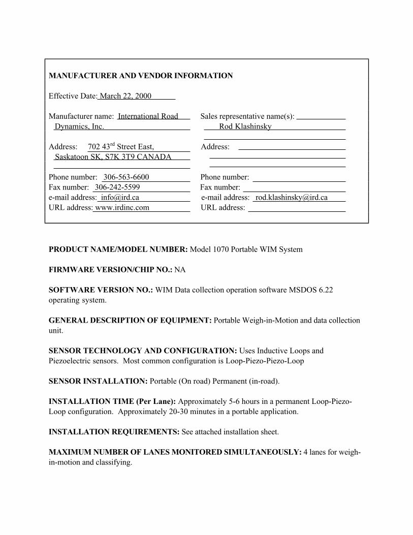
MANUFACTURER AND VENDOR INFORMATION
Effective Date: March 22, 2000
Manufacturer name: International Road Sales representative name(s):
Dynamics, Inc. Rod Klashinsky
Address: 702 43rd
Street East, Address:
Saskatoon SK, S7K 3T9 CANADA
Phone number: 306-563-6600 Phone number:
Fax number: 306-242-5599 Fax number:
e-mail address: [email protected] e-mail address: [email protected]
URL address: www.irdinc.com URL address:
PRODUCT NAME/MODEL NUMBER: Model 1070 Portable WIM System
FIRMWARE VERSION/CHIP NO.: NA
SOFTWARE VERSION NO.: WIM Data collection operation software MSDOS 6.22
operating system.
GENERAL DESCRIPTION OF EQUIPMENT: Portable Weigh-in-Motion and data collection
unit.
SENSOR TECHNOLOGY AND CONFIGURATION: Uses Inductive Loops and
Piezoelectric sensors. Most common configuration is Loop-Piezo-Piezo-Loop
SENSOR INSTALLATION: Portable (On road) Permanent (in-road).
INSTALLATION TIME (Per Lane): Approximately 5-6 hours in a permanent Loop-Piezo-
Loop configuration. Approximately 20-30 minutes in a portable application.
INSTALLATION REQUIREMENTS: See attached installation sheet.
MAXIMUM NUMBER OF LANES MONITORED SIMULTANEOUSLY: 4 lanes for weigh-
in-motion and classifying.

PRODUCT CAPABILITIES/FUNCTIONS: Collects and stores vehicle weight data including
axle and gross vehicle weights.
RECOMMENDED APPLICATIONS: Weight enforcement, Traffic planning, safety, and audit.
POWER REQUIREMENTS (watts/amps): AC power for 12 volt, rechargeable battery. 24
hours operation with standard battery pack.
POWER OPTIONS: Additional battery units, solar package.
CLASSIFICATION ALGORITHMS: See attached.
TELEMETRY: RS232 port with baud rates from 300-19,200.
COMPUTER REQUIREMENTS: MSDOS lap top
DATA OUTPUT FORMATS: Standard Data reporting package.
SUPPORTING DATA BASE MANAGEMENT SYSTEM: Dependent on customer
requirements.
EQUIPMENT AND INSTALLATION COSTS (One-lane and four-lane): Permanent one
lane — approx. US $ 15,000.00, 4 lanes approx. US $ 25,000.00.
STATES CURRENTLY USING THIS EQUIPMENT:
Country/State Contact name Telephone numberUSA/Nebraska
USA/Colorado
USA/North Carolina
USA/West Virginia
Canada/Saskatchewan
Canada/Ontario
Canada/New Brunswick
Argentina
Mexico
Japan
Korea
India

MANUFACTURER AND VENDOR INFORMATION
Effective Date: March 22, 2000
Manufacturer name: International Road Sales representative name(s):
Dynamics, Inc. Rod Klashinsky
Address: 702 43rd
Street East, Saskatoon Address:
SK, S7K 3T9 CANADA
Phone number: 306-653-6600 Phone number:
Fax number: 306-242-5599 Fax number:
e-mail address: [email protected] e-mail address: [email protected]
URL address www.irdinc.com: URL address:
PRODUCT NAME/MODEL NUMBER: Model 8000 Weigh-In-Motion Mat.
FIRMWARE VERSION/CHIP NO.: NA
SOFTWARE VERSION NO.: MS-DOS 6.2
GENERAL DESCRIPTION OF EQUIPMENT: Portable AC/DC powered vehicle weighing and
screening device.
SENSOR TECHNOLOGY AND CONFIGURATION: Uses flat rectangular capacitance pads
(2 per lane).
SENSOR INSTALLATION: Portable, lay flat on road.
INSTALLATION TIME (Per Lane): Set-up time-less than 10 minutes.
INSTALLATION REQUIREMENTS: Portable
MAXIMUM NUMBER OF LANES MONITORED SIMULTANEOUSLY: One lane, slow
speed (0-24 Km).
PRODUCT CAPABILITIES/FUNCTIONS: Weighs trucks to screen for overweight vehicles.

RECOMMENDED APPLICATIONS: Prescreening for Weigh Stations, Random Spot Checks,
Mobile Weigh.
POWER REQUIREMENTS (watts/amps): AC Power or DC power (through automobile
lighter)
POWER OPTIONS: AC or DC
CLASSIFICATION ALGORITHMS: See attached specifications
TELEMETRY: NA
COMPUTER REQUIREMENTS: Laptop computer supplied with system
DATA OUTPUT FORMATS: Vehicle information stored in data files and also sent to printer.
SUPPORTING DATA BASE MANAGEMENT SYSTEM: Dependent upon customer
requirements.
EQUIPMENT AND INSTALLATION COSTS (One-lane and four-lane): Equipment costs
US $ 18,5000.00 for complete system.
STATES CURRENTLY USING THIS EQUIPMENT:
Country/State Contact name Telephone numberUSA/Wisconsin
USA/North Dakota
Brazil
Uruguay
Korea

MANUFACTURER AND VENDOR INFORMATION
Effective Date: March 22, 2000
Manufacturer name: Sales representative name(s):
International Road Dynamics Inc. Rod Klashinsky
Address: Address:
702 43rd
Street East
Saskatoon SK, S7K3T9 Canada
Phone number: (306) 653-6600 Phone number:
Fax number: (306) 242-5599 Fax number:
e-mail address: [email protected] e-mail address: [email protected]
URL address: www.irdinc.com URL address:
PRODUCT NAME/MODEL NUMBER: IRD 1068 Single Load Cell Scale (SLC) WIM System
FIRMWARE VERSION/CHIP NO.: N/A
SOFTWARE VERSION NO.: N/A
GENERAL DESCRIPTION OF EQUIPMENT: The IRD 1068 Single Load Cell (SLC) scale
WIM system utilizes Single Load Cell (SLC) scale technology to collect data on axle weights,
vehicle classification (based on the number and spacing of axles) and vehicle speed. The system
is accessible remotely using a standard telephone communication modem and PC for system
monitoring, set-up and data collection.
SENSOR TECHNOLOGY AND CONFIGURATION: The system uses an inductive loop
Single Load Cell scale — piezo sensor loop configuration to collect traffic data.
SENSOR INSTALLATION: Please see attached product information for details
INSTALLATION TIME (Per Lane): Approximately 3 days per lane
INSTALLATION REQUIREMENTS: Please see attached product information for details
MAXIMUM NUMBER OF LANES MONITORED SIMULTANEOUSLY: 6

PRODUCT CAPABILITIES/FUNCTIONS: Vehicle WIM data collection
RECOMMENDED APPLICATIONS: Vehicle WIM data collection
POWER REQUIREMENTS (watts/amps): 2.5 Amps/35 watts
POWER OPTIONS: 100-240 VAC, 50-60 Hz
CLASSIFICATION ALGORITHMS: Vehicles can be classified based on axle weights, axle
spacings, axle groupings and GVW.
TELEMETRY: Terminal software and standard telephone line with modem required.
COMPUTER REQUIREMENTS: Pentium II or better, 400 MHZ min, 32 Mb RAM min,
Expansion slots 1 ISA, 3PCI, 1 ISA/PCI.
DATA OUTPUT: Individual vehicle and vehicle summary data are stored on the WIM computer
which can be retrieved through a modem. Individual data can also be sent to an RS 232 port on
the WIM in realtime.
DATA OUTPUT FORMATS: The vehicle information is stored on disk files in a compressed
format developed by IRD. Software is available to convert the data to CSV (Comma, Separated
Value) file. Several industry standard formats are available for the WIM vehicle data transmitted
through the RS 232 port.
SUPPORTING DATA BASE MANAGEMENT SYSTEM: Report generation software is
available form IRD that reads the compressed vehicle data files directly. Raw data can also be
exported to file which can be read by any database system.
EQUIPMENT COSTS (One-lane and four-lane):1-lane: $75,000 US
4-lane: $215,000 US
STATES CURRENTLY USING THIS EQUIPMENT:
Country/State Contact name Telephone numberUSA/Indiana (INDOT) Don Klepinger (317) 591-5264
USA/Minnesota (MNDOT) Mark Novak (651) 296-2607

MANUFACTURER AND VENDOR INFORMATION
Effective Date: 3/1/2000
Manufacturer name: Haenni/Mikros Sales representative name(s):
Loadometer Corporation
3-G Nashua Court
Address: Address: Baltimore, MD 21221-3133
Phone number: Phone number: (800) 753-6696
Fax number: Fax number: (410) 574-2856
e-mail address: e-mail address: [email protected]
URL address: URL address: www.loadometer.com
PRODUCT NAME/MODEL NUMBER: WL110, Low Speed Portable WIM
FIRMWARE VERSION/CHIP NO.:
SOFTWARE VERSION NO.:
GENERAL DESCRIPTION OF EQUIPMENT: System consists of 2 sensors, 4 leveling mats,
connecting cables and hand held monitor.
SENSOR TECHNOLOGY AND CONFIGURATION: Capacitance mat, stainless steel
construction
SENSOR INSTALLATION: None, aboveground
INSTALLATION TIME (Per Lane): 5 minutes
INSTALLATION REQUIREMENTS: None
MAXIMUM NUMBER OF LANES MONITORED SIMULTANEOUSLY: One
PRODUCT CAPABILITIES/FUNCTIONS: Capable of providing wheel loads, axle loads, axle
group loads, gross vehicle weight and violations per set parameters
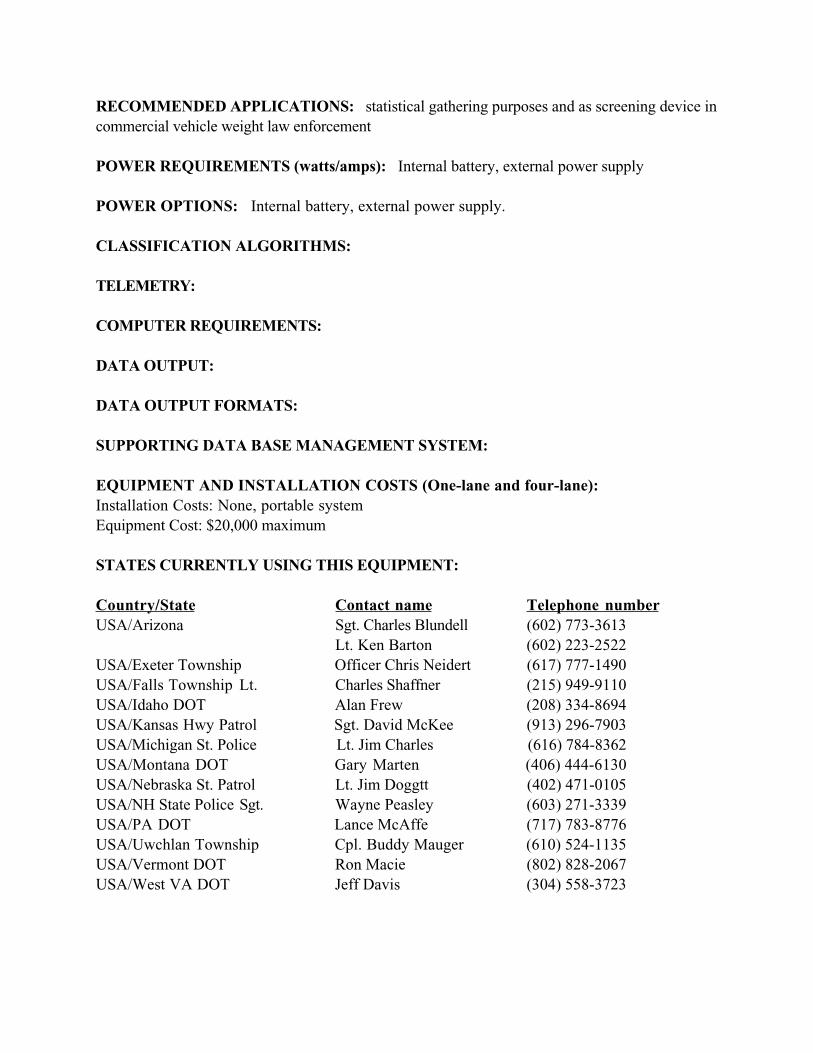
RECOMMENDED APPLICATIONS: statistical gathering purposes and as screening device in
commercial vehicle weight law enforcement
POWER REQUIREMENTS (watts/amps): Internal battery, external power supply
POWER OPTIONS: Internal battery, external power supply.
CLASSIFICATION ALGORITHMS:
TELEMETRY:
COMPUTER REQUIREMENTS:
DATA OUTPUT:
DATA OUTPUT FORMATS:
SUPPORTING DATA BASE MANAGEMENT SYSTEM:
EQUIPMENT AND INSTALLATION COSTS (One-lane and four-lane):Installation Costs: None, portable system
Equipment Cost: $20,000 maximum
STATES CURRENTLY USING THIS EQUIPMENT:
Country/State Contact name Telephone numberUSA/Arizona Sgt. Charles Blundell (602) 773-3613
Lt. Ken Barton (602) 223-2522
USA/Exeter Township Officer Chris Neidert (617) 777-1490
USA/Falls Township Lt. Charles Shaffner (215) 949-9110
USA/Idaho DOT Alan Frew (208) 334-8694
USA/Kansas Hwy Patrol Sgt. David McKee (913) 296-7903
USA/Michigan St. Police Lt. Jim Charles (616) 784-8362
USA/Montana DOT Gary Marten (406) 444-6130
USA/Nebraska St. Patrol Lt. Jim Doggtt (402) 471-0105
USA/NH State Police Sgt. Wayne Peasley (603) 271-3339
USA/PA DOT Lance McAffe (717) 783-8776
USA/Uwchlan Township Cpl. Buddy Mauger (610) 524-1135
USA/Vermont DOT Ron Macie (802) 828-2067
USA/West VA DOT Jeff Davis (304) 558-3723

MANUFACTURER AND VENDOR INFORMATION
Effective Date:March 22, 2000
Manufacturer name: International Road Sales representative name(s): Rod Klashinsky
Dynamics, Inc.
Address: 702 43rd
Street East Address:
Saskatoon SK, S7K 3T9 Canada
Phone number: 306-653-6600 Phone number:
Fax number: 306-242-5599 Fax number:
e-mail address: [email protected] e-mail address: [email protected]
URL address: www.irdinc.com URL address:
PRODUCT NAME/MODEL NUMBER: IRD Dynamic Work-Zone Safety System
FIRMWARE VERSION/CHIP NO.: NA
SOFTWARE VERSION NO.: NA
GENERAL DESCRIPTION OF EQUIPMENT: The IRD Work-Zon e Safety System is a
traffic control system for construction work zones. The system utilizes traffic detection sensors
to detect traffic queue length and reduce the number of vehicles in the passing lane prior to work-
zone approaches.
SENSOR TECHNOLOGY AND CONFIGURATION: The IRD Dynamic work-Zone Safety
System utilizes traffic sensors to detect vehicles and activate flashing lights mounted on DO
NOT PASS panel signs prior to construction zones. Alternately, CMS or VMS signs can be
used.
SENSOR INSTALLATION: Sensors are mounted on roadside panel message signs.
INSTALLATION TIME (Per Lane): The system can typically be installed in 4-5 days.
INSTALLATION REQUIREMENTS: Please see attached product information for details.

MAXIMUM NUMBER OF LANES MONITORED SIMULTANEOUSLY: Only one lane is
required to be monitored for this application.
PRODUCT CAPABILITIES/FUNCTIONS: Detection of vehicles prior to a work-zone to
trigger flashing lights mounted on roadway panel signs to instruct vehicles to merge into one lane.
Since the signs are regulatory signs, offences are enforceable by law.
RECOMMENDED APPLICATIONS: Detection of vehicles prior to a work-zone to trigger
flashing lights mounted on roadway panel signs.
POWER REQUIREMENTS (watts/amps): 12-24 AC or DC
POWER OPTIONS: AC, DC, or solar.
CLASSIFICATION ALGORITHMS: NA
TELEMETRY: NA
COMPUTER REQUIREMENTS: Laptop may be used to access information using serial
communications software such as HyperTerminal.
DATA OUTPUT: Serial or contact Closure.
DATA OUTPUT FORMATS: ASCII
SUPPORTING DATA BASE MANAGEMENT SYSTEM: NA
EQUIPMENT AND INSTALLATION COSTS (One-lane and four-lane):Approximately $ 60,000 US depending on the requirements (trailer and sign costs not included).
STATES CURRENTLY USING THIS EQUIPMENT:
Country/State Contact name Telephone numberUSA/Indiana (IN DOT) Dan Shamo (317) 232-5533

5-1
Chapter 5 — Non-intrusive Technologies
Non-intrusive technologies are those that do not require the installation of the sensor directly
onto or into the road surface. The sensors for non-intrusive technologies are mounted overhead
or on the side of the roadway. The video image processor, microwave radar, active and passive
infrared sensors, ultrasonic sensors, and passive acoustic array sensors are discussed in the
following sections.
Video Image Processor
Video cameras were introduced to traffic management for roadway surveillance because of their
ability to transmit closed circuit television imagery to a human operator for interpretation.
Present-day traffic management applications use video image processing to automatically analyze
the scene of interest and extract information for traffic surveillance and control. A video image
processor (VIP) system typically consists of one or more cameras, a microprocessor-based
computer for digitizing and processing the imagery, and software for interpreting the images and
converting them into traffic flow data.
Principles of Operation
Video image processor systems detect vehicles by analyzing the imagery from a traffic scene to
determine changes between successive frames. The image processing algorithms that analyze
black and white imagery examine the variation of gray levels in groups of pixels contained in the
video frames. The algorithms are designed to remove gray level variations in the image
background caused by weather conditions, shadows, and daytime or nighttime artifacts and retain
objects identified as automobiles, trucks, motorcycles, and bicycles. Traffic flow parameters are
calculated by analyzing successive video frames. Color imagery can also be exploited to obtain
traffic flow data. However, somewhat reduced dynamic range and sensitivity have so far
inhibited this approach.

5-2
Three classes of VIP systems have been developed: tripline, closed-loop tracking, and data
association tracking. Tripline systems operate by allowing the user to define a limited number of
detection zones in the field of view of the video camera. When a vehicle crosses one of these
zones, it is identified by noting changes in the pixels caused by the vehicle relative to the
roadway in the absence of a vehicle. Surface-based and grid-based analyses are utilized to detect
vehicles in tripline VIPs. The surface-based approach identifies edge features, while the grid
based classifies squares on a fixed grid as containing moving vehicles, stopped vehicles, or no
vehicles. Tripline systems estimate vehicle speed by measuring the time it takes an identified
vehicle to travel a detection zone of known length. The speed is found as the length divided by
the travel time (Klein, 2001).
The advent of the VIP tracking approaches has been facilitated by low-cost, high throughput
microprocessors. Closed-loop tracking systems are an extension of the tripline approach that
permits vehicle detection along larger roadway sections. The closed-loop systems track vehicles
continuously through the field of view of the camera. Multiple detections of the vehicle along a
track are used to validate the detection. Once validated, the vehicle is counted and its speed is
updated by the tracking algorithm (MacCarley, 1992). These tracking systems may provide
additional traffic flow data such as lane-to-lane vehicle movements. Therefore, they have the
potential to transmit information to roadside displays and radios to alert drivers to erratic
behavior that can lead to an incident.
Data association tracking systems identify and track a particular vehicle or groups of vehicles as
they pass through the field of view of the camera. The computer identifies vehicles by searching
for unique connected areas of pixels. These areas are then tracked from frame-to-frame to
produce tracking data for the selected vehicle or vehicle groups. The markers that identify the
objects are based on gradients and morphology. Gradient markers utilize edges, while
morphological markers utilize combinations of features and sizes that are recognized as belonging

5-3
to known vehicles or groups of vehicles (Wentworth, et. al., 1994). In the future, data
association tracking may provide link travel time and origin-destination pair information by
identifying and tracking vehicles as they pass from one camera s field of view to another s.
Figure 16 shows two examples of video image processors that use the tripline approach.
Figure 16. Video image processors.
Signal Processing
Image formatting and data extraction are performed with firmware that allows the algorithms to
run in real time. The hardware that digitizes the video imagery is commonly implemented on a
single-formatter card in a personal computer architecture. Once the data are digitized and stored
by the formatter, spatial and temporal features are extracted from the vehicles in each detection
area with a series of image processing algorithms. In the concept illustrated in Figure 17, a
detection process establishes one or more thresholds that limit and segregate the data passed on
to the rest of the algorithms. It is undesirable to severely limit the number of potential vehicles
during detection, for once data are removed they cannot be recovered. Therefore, false vehicle
detections are permitted at this stage since the declaration of actual vehicles is not made at the
conclusion of the detection process. Rather, algorithms that are part of the classification,
identification, and tracking processes still to come are relied on to eliminate false vehicles and
retain the real ones (Klein, 1997). Image segmentation is used to divide the image area into
smaller regions where features can be better recognized. The features are analyzed to generate
Autoscope 2004 (Photograph courtesy ofEconolite Control Products, Anaheim, CA)
VideoTrak-900 (Photograph courtesy ofTransyt Corp., Tallahassee, FL)

5-4
vehicle presence, speed, and classification data. VIPs with tracking capability use Kalman filter
techniques to update vehicle position and velocity estimates. The time trace of the position
estimates yields a vehicle trajectory, which can supply lane change and turning information.
A signal processing approach implemented by Computer Recognition Systems incorporates
wireframe models composed of line segments to represent vehicles in the image. This approach
claims to provide more unique and discriminating features than other computationally viable
techniques. Alternatively, artificial neural networks can be trained to recognize and count
different classes of vehicles and detect incidents (Chang & Kunhuang, 1993). The neural network
approach is incorporated by Nestor Traffic Systems, Inc. in their VIP products. An advantage of
the Nestor implementation is that the camera can be repositioned for data acquisition and
surveillance (Nestor Corp., 1999). VIPs that utilize tracking offer the ability to warn of
impending incidents due to abrupt lane changes or weaving, calculate link travel times, and
determine origin-destination pairs. The tracking concept is found in the Mobilizer by CMS,
MEDIA4 by Citilog, and IDET-2000 by Sumitomo (Klein, 2001)
Traffic Under
Observation CameraImage Digitization
and StorageDetection
Image
Segmentation
Feature
ExtractionClassification and
IdentificationTracking
Figure 17. Conceptual image processing for vehicle detection, classification, andtracking.

5-5
Application and Uses
A VIP can replace several in-ground inductive loops, provide detection of vehicles across several
lanes, and perhaps lower maintenance costs. Some VIP systems process data from more than
one camera and further expand the area over which data are collected. VIPs can classify vehicles
by their length and report vehicle presence, flow rate, occupancy, and speed for each class.
Other potentially available traffic parameters that can be obtained by analyzing data from a series
of image processors installed along a section of roadway are density, link travel time, and origin-
destination pairs.
Mounting and Traffic Viewing Considerations
VIP cameras can be deployed to view upstream or downstream traffic. The primary advantage of
upstream viewing is that incidents are not blocked by the resultant traffic queues as described in
Table 11. However, tall vehicles such as trucks may block the line of sight and headlights may
cause blooming of the imagery at night. With upstream viewing, headlight beams can be detected
as vehicles in adjacent lanes on curved road sections. Downstream viewing conceals cameras
mounted on overpasses so that driver behavior is not altered. Downstream viewing also makes
vehicle identification easier at night through the information available in the taillights and
enhances track initiation because vehicles are first detected when close to the camera.
Although some manufacturers quote a maximum surveillance range for a VIP of ten times the
camera mounting height, conservative design procedures limit the range to smaller distances
because of factors such as road configuration (e.g., elevation changes, curvature, and overhead or
underpass structures), congestion level, vehicle mix, and inclement weather.
Other factors that affect camera installation include vertical and lateral viewing angles, number of
lanes observed, stability with respect to wind and vibration, and image quality. VIP cameras can
be mounted on the side of a roadway if the mounting height is high, that is 50 ft (15.2 m) or
greater. For lower mounting heights of 20 to 30 ft (6.1 to 9.1 m), a centralized location over the

5-6
middle of the roadway area of interest is required. However, the lower the camera mounting, the
greater is the error in vehicle speed measurement, as the measurement error is proportional to the
vehicle height divided by the camera mounting height. The number of lanes of imagery analyzed
by the VIP becomes important when the required observation and analysis area is larger than the
VIP s capability. For example, if the VIP provides data from detection zones in three lanes, but
five must be observed, that particular VIP may not be appropriate for the application. VIPs that
are sensitive to large camera motion may be adversely affected by high winds as the processor
may assume that the wind-produced changes in background pixels correspond to vehicle motion.
Image quality and interpretation can be affected by cameras that have automatic iris and
automatic gain control. In tests conducted by California Polytechnic Institute at San Luis Obispo
(Cal Poly SLO), these systems were disabled (Hockaday, 1991). In follow-up tests, Cal Poly
SLO found VIPs better able to compensate for light level changes when the automatic iris was set
to respond slowly to variations in light entering the camera.
Table 11.Video image processor characteristics in upstream and downstream viewing.
Upstream Viewing Downstream Viewing
• Headlight blooming, glare on wet pavement,
headlight beams detected in adjacent lanes on
curved road sections
• More blockage from tall trucks
• Camera on overpass concealed from drivers
• More information from tail lights available for
braking indication, vehicle classification, and
turning movement identification
• Traffic incidents are not blocked by resulting
traffic queues
• With long wavelength infrared imagery,
similar information is available to a tracking
algorithm from headlight and tail light
viewing
• Easier to acquire vehicles that are closer
to the camera for the tracking algorithm
application
• With visible imagery, more information
is available to a tracking algorithm from tail
light viewing
Advantages
VIP signal processing is continually improving its ability to recognize artifacts produced by
shadows, illumination changes, reflections, inclement weather, and camera motion from wind or
vehicle-induced vibration. However, artifacts persist and the user should evaluate VIP
5-7
performance under the above conditions and other local conditions that may exist. In their 1998
report to the TRB Freeway Operations Committee, the New York State Department of
Transportation (DOT) stated that one VIP model had difficulty detecting vehicles on a roadway
lightly covered with snow in good visibility. Another model did not experience this problem. An
example of the effect of day-to-night illumination change on VIP performance is illustrated in
Figure 18. Shortly after 1900 hours, there are changes in the slopes of the vehicle count data
produced by the VIPs due to either degradation in performance of the daytime algorithm or the
different performance of the nighttime algorithm (Klein, 1996).
Heavy congestion that degraded early VIPs does not appear to present a problem to more
modern systems. Combined results for clear and inclement weather show vehicle flow rate,
speed, and occupancy measurement accuracies in excess of 95 percent using a single detection
zone and a camera mounted at a sufficiently high height (Michalopoulos, et. al., 1993). VIPs
with single or multiple detection zones per lane can be used to monitor traffic on a freeway. For
signalized intersection control, where vehicle detection accuracies of 100 percent are desired, the
number of detection zones per lane is increased to between two and four, dependent on the
camera mounting and road geometry. Even with multiple detection zones, cameras used in a side-
viewing configuration that are not mounted high enough, on the order of 30 ft (9 m) rather than 50
ft (15 m)] or are not directly adjacent to the roadway can degrade the vehicle detection accuracy
to 85 percent or less (Klein, 1999 vols. 1&2). The study that produced these results also
reported that vehicle detection was sometimes sensitive to the vehicle-to-road color contrast.
Disadvantages
Some disadvantages of the video image processor include its vulnerability to viewing
obstructions; inclement weather; shadows; vehicle projection into adjacent lanes; occlusion; day-
to-night transition; vehicle/road contrast; water; salt grime; icicles; and cobwebs on camera lens
that can affect performance. Also, some models are susceptible to camera motion caused by

5-8
strong winds. Furthermore, the installation of a video image processor requires 50 to 60-feet
mounting height (in a side mounting configuration) for optimum presence detection and speed
measurement. A video image processor arrangement is generally cost effective only if many
detection zones are required within the field of view of the camera.
Figure 18. Vehicle count comparison from four VIPs and inductive loopdetectors.
VI P 2
VIP 3 * *
VIP 1
VIP 4 * **
Time of Day
16 00 17 00 1800 1900 2000 2100 2200
20 00
15 00
10 00
500
0
** Softwa re was eventually mod ified to imp ro ve nighttime perform ance.*** This VIP was not designe d to cou nt veh icles. It produced a
presence output every 1 se cond t hat indicated if one or morevehicles had been detected during the previous 1-second interval.
Veh
icle
Cou
nt
Sen sor Coun ts % Differe nce*
Squ are ILD 2 1600 0
Round ILD 1 1603 +0.2
Round ILD 2 1608 +0.5
VIP 1 1536 -4.0
VIP 2 1681 +5.1
VIP 3 ** 1339 -16.3
VIP 4 *** 1246 -22.1
* Computed with respect to squa re ILD 2
Surface stre et arterial evalua tion site. Warm, dry weather. Curb lane.
Squ are andround ILDs

MANUFACTURER AND VENDOR INFORMATION
Effective Date: April 4, 2000
Manufacturer name: Sales representative name(s):
Enerdyne Technologies, Inc Robert Perez
Address: Address:
8402 Magnolia Avenue 8402 Magnolia Avenue
Santee, CO 92071 Santee, CO 92071
Phone number: (619) 562-3061 Phone number: (619) 562-3061
Fax number: Fax number:
e-mail address: e-mail address: [email protected]
URL address: URL address: enerdyne.com
PRODUCT NAME/MODEL NUMBER: Linux Communication Server Lnx7000
FIRMWARE VERSION/CHIP NO.:
SOFTWARE VERSION NO.:
GENERAL DESCRIPTION OF EQUIPMENT: Stand alone high speed data server
multipleasing and de-multiplying video, audio and data using IP. Supports mpeg 2/1 and mjpeg.
SENSOR TECHNOLOGY AND CONFIGURATION:
SENSOR INSTALLATION:
INSTALLATION TIME (Per Lane):
INSTALLATION REQUIREMENTS:.
MAXIMUM NUMBER OF LANES MONITORED SIMULTANEOUSLY:
PRODUCT CAPABILITIES/FUNCTIONS: Product supports mpeg —mpeg2 and mjpeg. IP
based with a 10 baset and a 10/100 ethernet pint. Supports a single pumcia slot for options.
Internal webserver.

RECOMMENDED APPLICATIONS: Traffic surveillance
POWER REQUIREMENTS (watts/amps): 11 watts
POWER OPTIONS:
CLASSIFICATION ALGORITHMS:
TELEMETRY:
COMPUTER REQUIREMENTS:
DATA OUTPUT:
DATA OUTPUT FORMATS:
SUPPORTING DATA BASE MANAGEMENT SYSTEM:
EQUIPMENT COSTS (One-lane and four-lane): Equipment pricing range from mid $5,000
to approximately $7,000 per device.
STATES CURRENTLY USING THIS EQUIPMENT:
Country/State Contact name Telephone number
CONTACT ENERDYNE TECHNOLOGIES FOR CURRENT LIST OF REFERENCES.

MANUFACTURER AND VENDOR INFORMATION
Effective Date: 3/1/2000
Manufacturer name: Image Sensing Sales representative name(s):
Systems, Inc.
Address: 1600 University Avenue West Address:
500 Spruce Tree Centre
St. Paul, MN 55104-3823
Phone number: (651) 603-7700 Phone number:
Fax number: (651) 603-7795 Fax number:
e-mail address: e-mail address:
URL address: URL address:
PRODUCT NAME/MODEL NUMBER: Autoscope (5 models)
Autoscope — 2004, 2004LE, 2004ID
Autoscope — V8, Autoscope Solo
FIRMWARE VERSION/CHIP NO.: Various by model
SOFTWARE VERSION NO.: Various based upon model of Autoscope
GENERAL DESCRIPTION OF EQUIPMENT: Autoscope was the first video vehicle
detection system introduced in 1989. Currently, Autoscope holds more than 60% global market
share, with 3,000 systems installed globally
SENSOR TECHNOLOGY AND CONFIGURATION: Machine vision — video image
processing, pixel tracking and tripline technology
SENSOR INSTALLATION: Existing signal poles, mast arm and luminaire standards
INSTALLATION TIME (Per Lane): 12 hours
INSTALLATION REQUIREMENTS: Minimum 25 ft. aboveground — preferably 1:10 ft ratio
to detect
MAXIMUM NUMBER OF LANES MONITORED SIMULTANEOUSLY: Six to seven

PRODUCT CAPABILITIES/FUNCTIONS: Complete vehicle detection, preference, traffic
control, speed, occupancy, headway, queue length travel time, classification, automatic incident
detection, critical traffic alarms for intersection and freeway traffic, management, interface with
scout, scats, spot.
RECOMMENDED APPLICATIONS: Intersection detection, freeway/tollways mgt.
Construction zones, railway crossings, bridges, tunnels, security areas.
POWER REQUIREMENTS (watts/amps): 0.25 amps 110/220 50/60 MHz
POWER OPTIONS: AC
CLASSIFICATION ALGORITHMS: User selectable by length into 5 — 6 ins.
TELEMETRY: Proprietary based upon existing infrastructure
COMPUTER REQUIREMENTS: 486/Pentium minimum w/ Windows 98 or NT.
DATA OUTPUT: ASCI text format or compatible with multiple standard spreadsheet programs.
DATA OUTPUT FORMATS: Per above in time slices from 10-60 seconds and 5-60 minutes.
SUPPORTING DATA BASE MANAGEMENT SYSTEM: Contingent upon particular model
EQUIPMENT AND INSTALLATION COSTS (One-lane and four-lane):1 lane: $5,000
4 lane: 14 approach intersection, $18,200
STATES CURRENTLY USING THIS EQUIPMENT:
Country/State Contact name Telephone number
CONTACT IMAGE SENSING SYSTEMS FOR CURRENT LIST OF REFERENCES.

MANUFACTURER AND VENDOR INFORMATION
Effective Date: 2/29/00
Manufacturer name: Sales representative name(s):
Sumitomo Electric. Takehiko Barada
Address: 1-1-3 Shimaya Address: 3235 Kifer Road
Konohana-ku, Osaka 554-0024 Suite 150
Japan Santa Clara, CA 95051
Phone number: +81 6-6461-1031 Phone number: (408) 737-8517
Fax number: +81 6-6466-3305 Fax number: (408) 737-0134
e-mail address: [email protected] e-mail address: [email protected]
URL address: www.sel.co.jp URL address: www.sumitomo.com/its/
PRODUCT NAME/MODEL NUMBER: IDET - 1000
FIRMWARE VERSION/CHIP NO.: N/A
SOFTWARE VERSION NO.: N/A
GENERAL DESCRIPTION OF EQUIPMENT: Imaging Processing Vehicle Detector with
Multiple Features
SENSOR TECHNOLOGY AND CONFIGURATION: Video
SENSOR INSTALLATION: Overhead or sidefire
INSTALLATION TIME (Per Lane): N/A
INSTALLATION REQUIREMENTS: Pole arm
MAXIMUM NUMBER OF LANES MONITORED SIMULTANEOUSLY: Four
PRODUCT CAPABILITIES/FUNCTIONS: Presence, occupancy, classification (two-three),
speed stopped vehicle detection (drive lanes, shoulders) queue length measurement, 1 still image
transmission (JPEG format)

RECOMMENDED APPLICATIONS: Advanced traffic signal control, freeway monitoring,
ramp control incident management, tunnel traffic flow monitoring
POWER REQUIREMENTS (watts/amps): 50 va
POWER OPTIONS: N/A
CLASSIFICATION ALGORITHMS: Vehicle length (daytime), width (night)
TELEMETRY:
COMPUTER REQUIREMENTS: PC with RS-232 for installation and adjustment
DATA OUTPUT: NEMA TS1, RS 232 custom
DATA OUTPUT FORMATS: N/A
SUPPORTING DATA BASE MANAGEMENT SYSTEM: N/A
EQUIPMENT AND INSTALLATION COSTS (One-lane and four-lane): Approx.
$18,000/four lane & installation cost & communication
STATES CURRENTLY USING THIS EQUIPMENT:
Country/State Contact name Telephone numberJapan

MANUFACTURER AND VENDOR INFORMATION
Effective Date: 3/6/00
Manufacturer name: Iteris Sales representative name(s):
Mary Griffin
Mike Volling
Address: 1515 S. Manchester Avenue Address: same
Anaheim, CA 92802
Phone number: (800) 254-5487 Phone number: same
Fax number: (714) 780-7246 Fax number: same
e-mail address: [email protected] e-mail address: [email protected], [email protected]
URL address: www.iteris.com URL address:
PRODUCT NAME/MODEL NUMBER: Vantage One Video Detection Systems
FIRMWARE VERSION/CHIP NO.: 1.07
SOFTWARE VERSION NO.: 1.07
GENERAL DESCRIPTION OF EQUIPMENT: Single camera shelf or rack mount video
detection unit.
SENSOR TECHNOLOGY AND CONFIGURATION: Analog CCD — available in wired or
wireless configuration.
SENSOR INSTALLATION: Pole mount
INSTALLATION TIME (Per Lane): 15 — 30 minute average
INSTALLATION REQUIREMENTS: Bucket truck and camera bracket
MAXIMUM NUMBER OF LANES MONITORED SIMULTANEOUSLY: 1-6 lanes
PRODUCT CAPABILITIES/FUNCTIONS: Vehicle detection via camera, works in TS1 or
170/179 cabinet. Up to 24 zones, 8 outputs, remote access.

RECOMMENDED APPLICATIONS: Intersection and highway
POWER REQUIREMENTS (watts/amps): 24 VDC — processor
115 VAC, 60 Hz, 15 watt - camera
POWER OPTIONS:4 VDC – processor220 VAC, 50 Hz, 15 watt - camera
CLASSIFICATION ALGORITHMS: Count, presence, extend, delay, and pulse detector types
TELEMETRY: Via RS 232
COMPUTER REQUIREMENTS: None for setup or operation
DATA OUTPUT: 8 outputs
DATA OUTPUT FORMATS: Contact closure
SUPPORTING DATA BASE MANAGEMENT SYSTEM: VRAS — Vantage Remote
Access Software
EQUIPMENT AND INSTALLATION COSTS (One-lane and four-lane):$5,000.00 0 $6,500.00 per approach (1-6 lanes)
STATES CURRENTLY USING THIS EQUIPMENT:
Country/State Contact name Telephone numberUSA/Texas DOT Dexter Turner
USA/Virginia DOT Bobby Perdue
USA/City of Clovis, CA Tim Barker
USA/City of Victorville, CA George Parmenter

MANUFACTURER AND VENDOR INFORMATION
Effective Date: 3/6/00
Manufacturer name: Iteris Sales representative name(s):
Mary Griffin
Mike Volling
Address: 1515 S. Manchester Avenue Address: same
Anaheim, CA 92802
Phone number: (800) 254-5487 Phone number: same
Fax number: (714) 780-7246 Fax number: same
e-mail address: [email protected] e-mail address: [email protected], [email protected]
URL address: www.iteris.com URL address:
PRODUCT NAME/MODEL NUMBER: Vantage Edge Video Detection Systems
FIRMWARE VERSION/CHIP NO.: 1.07
SOFTWARE VERSION NO.: 1.07
GENERAL DESCRIPTION OF EQUIPMENT: Single camera rack mount video detection unit.
SENSOR TECHNOLOGY AND CONFIGURATION: Analog CCD camera available in wired
or wireless configuration.
SENSOR INSTALLATION: Pole mount
INSTALLATION TIME (Per Lane): 15 — 30 minute average
INSTALLATION REQUIREMENTS: Bucket truck and camera bracket
MAXIMUM NUMBER OF LANES MONITORED SIMULTANEOUSLY: 1-6 lanes
PRODUCT CAPABILITIES/FUNCTIONS: Vehicle detection via camera, works in TS1 or
170/179 cabinet. Up to 24 zones, 8 outputs, remote access.
RECOMMENDED APPLICATIONS: Intersection and highway

POWER REQUIREMENTS (watts/amps): 24 VDC — processor
115 VAC, 60 Hz, 15 watt - camera
POWER OPTIONS: 24 VDC — processor
220 VAC, 50 Hz, 15 watt - camera
CLASSIFICATION ALGORITHMS: Count, presence, extend, delay, and pulse detector types
TELEMETRY: Via RS 232
COMPUTER REQUIREMENTS: None for setup or operation
DATA OUTPUT: Contact closure; up to 8 outputs;
DATA OUTPUT FORMATS:
SUPPORTING DATA BASE MANAGEMENT SYSTEM: VRAS — Vantage Remote Access
Software
EQUIPMENT AND INSTALLATION COSTS (One-lane and four-lane):$5,000.00 0 $6,500.00 per approach (1-6 lanes)
STATES CURRENTLY USING THIS EQUIPMENT:
Country/State Contact name Telephone numberUSA/Texas DOT Dexter Turner
USA/Virginia DOT Bobby Perdue
USA/City of Clovis, CA Tim Barker
USA/City of Victorville, CA George Parmenter

MANUFACTURER AND VENDOR INFORMATION
Effective Date: 3/5/00
Manufacturer name: Iteris Sales representative name(s):
Mary Griffin
Mike Volling
Address: 1515 S. Manchester Avenue Address: same
Anaheim, CA 92802
Phone number: (800) 254-5487 Phone number: same
Fax number: (714) 780-7246 Fax number: same
e-mail address: [email protected] e-mail address: [email protected], [email protected]
URL address: www.iteris.com URL address:
PRODUCT NAME/MODEL NUMBER: Vantage Plus Video Detection Systems
FIRMWARE VERSION/CHIP NO.: 1.07
SOFTWARE VERSION NO.: 1.07
GENERAL DESCRIPTION OF EQUIPMENT: Video detection unit capable of 1-6 video
inputs. Modular in design, shelf, or rack mount chassis.
SENSOR TECHNOLOGY AND CONFIGURATION: Analog CCD camera available in wired
or wireless configuration.
SENSOR INSTALLATION: Pole mount
INSTALLATION TIME (Per Lane): 15 — 30 minute average
INSTALLATION REQUIREMENTS: Bucket truck and camera bracket
MAXIMUM NUMBER OF LANES MONITORED SIMULTANEOUSLY: 1- 36
PRODUCT CAPABILITIES/FUNCTIONS: Vehicle detection via camera Works in TS1, TS2,
or 170/179 cabinet. Up to 24 zones, 32 outputs, remote access.

RECOMMENDED APPLICATIONS: Intersection and highway
POWER REQUIREMENTS (watts/amps): 115 vac 60 Hz, 137 watt — processor
115 vac 60 Hz, 15 watts - camera
POWER OPTIONS: 220 vac, 50 Hz, 137 watt - camera
220 vac, 50 Hz, 15 watt - camera
CLASSIFICATION ALGORITHMS: Count, presence, extend, delay, and pulse detector types
TELEMETRY: Via RS 232
COMPUTER REQUIREMENTS: None for setup or operation
DATA OUTPUT: Contact closure or TS 2 (output); 32 outputs
DATA OUTPUT FORMATS:
SUPPORTING DATA BASE MANAGEMENT SYSTEM: VRAS — Vantage Remote Access
Software
EQUIPMENT AND INSTALLATION COSTS (One-lane and four-lane):$5,000.00 0 $6,500.00 per approach (1-6 lanes)
STATES CURRENTLY USING THIS EQUIPMENT:
Country/State Contact name Telephone numberUSA/Texas DOT Dexter Turner
USA/Virginia DOT Bobby Perdue
USA/City of Clovis, CA Tim Barker
USA/City of Victorville, CA George Parmenter

MANUFACTURER AND VENDOR INFORMATION
Effective Date: Fall 2000
Manufacturer name: Digital Image, Inc. Sales representative name(s):
Steven S. Suzuki
Address: 1005 N. Wolfe Road, SW2-240 Address: Same
Cupertino, CA 95014
Phone number: (408) 257-9057 Phone number: (408) 257-9057 ext. 306
Fax number: (408) 257-9674 Fax number:
e-mail address: [email protected] e-mail address: [email protected]
URL address: www.dii-megachips.com URL address:
PRODUCT NAME/MODEL NUMBER: MD-100
FIRMWARE VERSION/CHIP NO.:
SOFTWARE VERSION NO.:
GENERAL DESCRIPTION OF EQUIPMENT: Remote video sensor with audio support
SENSOR TECHNOLOGY AND CONFIGURATION: Video and audio
SENSOR INSTALLATION:
INSTALLATION TIME (Per Lane):
INSTALLATION REQUIREMENTS:
MAXIMUM NUMBER OF LANES MONITORED SIMULTANEOUSLY:
PRODUCT CAPABILITIES/FUNCTIONS: Four video inputs; full duplex audio support;
RS232C Ports for 3rd
party device control; 10 Base-T (Ethernet) port; video compression (RVC
or JPEG); web browser (view and control 3rd
party devices via Netscape Navigator or Internet
Explorer); alarm events recording

RECOMMENDED APPLICATIONS: Traffic Monitoring: highways, intersections, toll booths.
Video Surveillance: parking lots, day care centers, hotels, schools, stores. Remote
Monitoring/Maintenance: production lines, ship yards, airports, railroads.
POWER REQUIREMENTS (watts/amps): A/C 120V + 10%
POWER OPTIONS:
CLASSIFICATION ALGORITHMS:
TELEMETRY:
COMPUTER REQUIREMENTS: Windows PC/AT compatible. Operating systems: Windows
95 OSR2.1, Windows 98 2nd
edition, Windows NT 4.0 service pack 5. Web browser: Internet
Explorer 4.02 or 5.0, Netscape Communicator 4.7. Full duplex sound card capable of
simultaneous recording and replay. Microphones and speakers capable of connecting to the above
sound card. Minimum CPU: Pentium II 333 MHz or higher (Pentium III 500 MHz
recommended). Memory: 64 MB (128 MB recommended)
DATA OUTPUT: Video and audio
DATA OUTPUT FORMATS:
SUPPORTING DATA BASE MANAGEMENT SYSTEM:
EQUIPMENT AND INSTALLATION COSTS (One-lane and four-lane):CONTACT DIGITAL IMAGE INC. FOR EQUIPMENT AND INSTALLATION COSTS.
STATES CURRENTLY USING THIS EQUIPMENT:
Country/State Contact name Telephone number
CONTACT DIGITAL IMAGE INC. FOR CURRENT LIST OF USERS.

MANUFACTURER AND VENDOR INFORMATION
Effective Date: August 21, 2000
Manufacturer name: TraFicon Sales representative name(s):
Mike Day: Control Technologies
Address: Bissegemse Street 45 Address: 2776 Financial Court
B-8501 Heule, Belgium Sanford, Florida 32773
Phone number: 32-56 37 2200 Phone number: (407) 330-2800
Fax number: 32-56 37 2196 Fax number: (407) 330-2804
e-mail address: [email protected] e-mail address: [email protected]
URL address: traficon.be URL address: www.cttraffic.com
PRODUCT NAME/MODEL NUMBER: VIP 3.1
FIRMWARE VERSION/CHIP NO.: 2.06e
SOFTWARE VERSION NO.: 2.06e
GENERAL DESCRIPTION OF EQUIPMENT: Single approach detection
SENSOR TECHNOLOGY AND CONFIGURATION: Video modular by approach
SENSOR INSTALLATION: Mast arm, side of pole
INSTALLATION TIME (Per Lane): One hour
INSTALLATION REQUIREMENTS: Bucket truck
MAXIMUM NUMBER OF LANES MONITORED SIMULTANEOUSLY: Eight
PRODUCT CAPABILITIES/FUNCTIONS: Presence detection, counting, video surveillance
RECOMMENDED APPLICATIONS: Presence detection, freeway management, counts, ramp
metering detection, volume, speed
POWER REQUIREMENTS (watts/amps): 120 V, 5W

POWER OPTIONS: 12V D/C
CLASSIFICATION ALGORITHMS: Available
TELEMETRY: Available
COMPUTER REQUIREMENTS: Not mandatory
DATA OUTPUT: Presence, volume, speed
DATA OUTPUT FORMATS:
SUPPORTING DATA BASE MANAGEMENT SYSTEM: Watts Traffic Management
Software (PC - based)
EQUIPMENT AND INSTALLATION COSTS (One-lane and four-lane): Approximately
$5,000 per approach
STATES CURRENTLY USING THIS EQUIPMENT:
Country/State Contact name Telephone numberUSA/Florida Carl Morse (850) 850-8871
USA/Florida Garry Lester (904) 736-5968
USA/Florida Richard Epps (941) 694-1332
USA/Geogia B. Smith (404) 635-8117

5-9
Microwave Radar
Microwave radar was developed for detecting objects before and during Word War II. The word
radar was derived from the functions that it performs: RAdio Detection And Ranging. The term
microwave refers to the wavelength of the transmitted energy, usually between 1 and 30 cm.
This corresponds to a frequency range of 1 GHz to 30 GHz, where the suffix GHz represents
109 Hz. Microwave sensors designed for roadside traffic data collection and monitoring in the
U.S. are limited by FCC regulations to operating frequency bands near 10.5, 24.0, and 34.0 GHz.
These requirements, as well as others that restrict the transmitted power, are satisfied by the
sensor manufacturers. Thus, the end users are not required to possess special licenses or test
equipment to verify the output frequency or power of the devices. Radars at frequencies above
30 GHz operate in the millimeter-wave spectrum since the wavelength of the transmitted energy
is expressed in terms of millimeters. Most commercially available microwave radar sensors used
in traffic management applications transmit electromagnetic energy at the X-band frequency of
10.525 GHz. Higher frequencies can illuminate smaller ground areas with a given size antenna
and thus gather higher resolution data. Vehicle-mounted radars operating at 76 to 77 GHz
support obstacle detection and automatic cruise control.
Principles of Operation
As shown in Figure 19, roadside-mounted microwave radar transmit energy toward an area of the
roadway from an overhead antenna. The beamwidth or area in which the radar energy is
transmitted, is controlled by the size and the distribution of energy across the aperture of the
antenna. The manufacturer usually establishes the design constraints. When a vehicle passes
through the antenna beam, a portion of the transmitted energy is reflected back towards the
antenna. The energy then enters a receiver where the detection is made and vehicle data, such as
volume, speed, occupancy, and length are calculated.
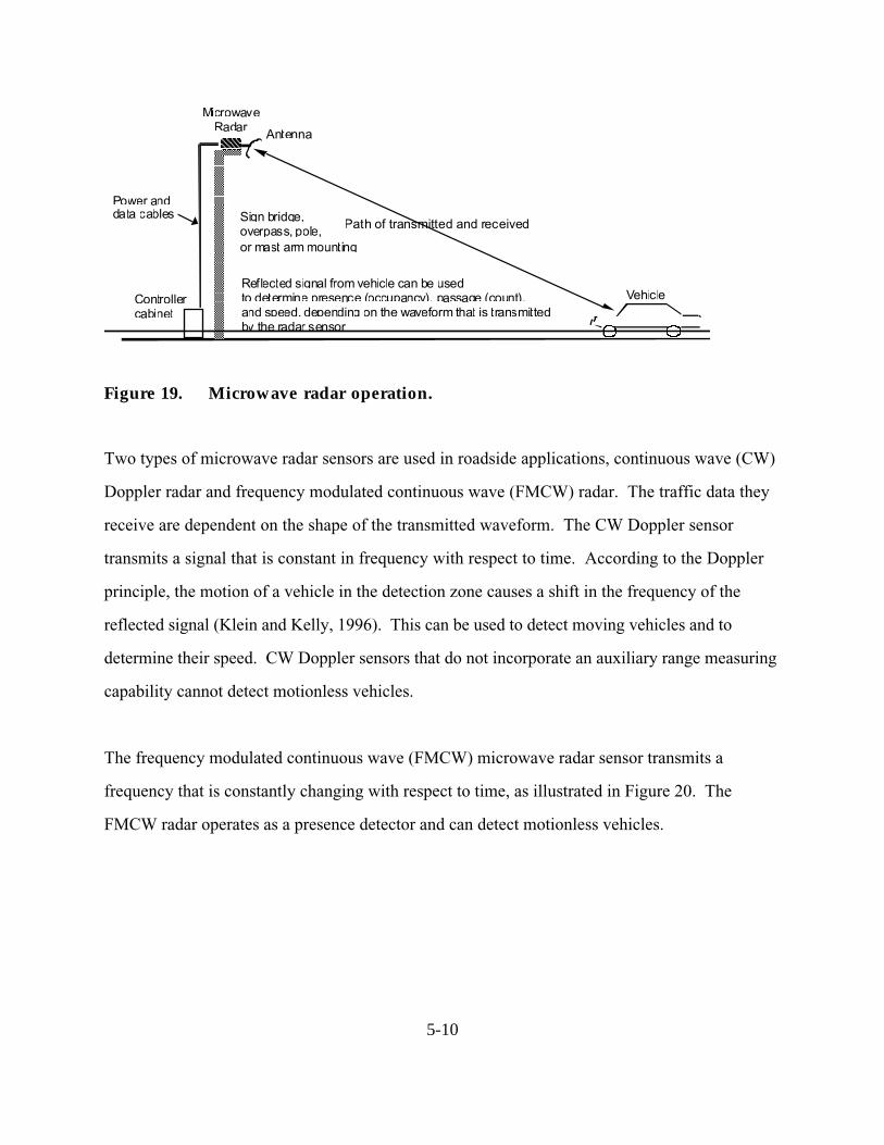
5-10
Vehicle
Path of transmitted and received
MicrowaveRadar Antenna
Sign bridge,overpass, pole,or mast arm mounting
Reflected signal from vehicle can be usedto determine presence (occupancy), passage (count),and speed, depending on the waveform that is transmittedby the radar sensor
Controllercabinet
Power anddata cables
Figure 19. Microwave radar operation.
Two types of microwave radar sensors are used in roadside applications, continuous wave (CW)
Doppler radar and frequency modulated continuous wave (FMCW) radar. The traffic data they
receive are dependent on the shape of the transmitted waveform. The CW Doppler sensor
transmits a signal that is constant in frequency with respect to time. According to the Doppler
principle, the motion of a vehicle in the detection zone causes a shift in the frequency of the
reflected signal (Klein and Kelly, 1996). This can be used to detect moving vehicles and to
determine their speed. CW Doppler sensors that do not incorporate an auxiliary range measuring
capability cannot detect motionless vehicles.
The frequency modulated continuous wave (FMCW) microwave radar sensor transmits a
frequency that is constantly changing with respect to time, as illustrated in Figure 20. The
FMCW radar operates as a presence detector and can detect motionless vehicles.

5-11
Direction of traffic flow
Timet1 t2
∆F ∆f
Lane 1
Lane 2
Lane 3 d
Frequency
Elliptical field of viewor footprint of antenna
Microwave radar sensor
Antenna
(b) Range binned footprints of radar sensors in traffic lanes
(a) FMCW waveform
Range bin 2Range bin 1
Tm = 1/fm
∆T
(c) Time-phased outputs of range bins
Time
Time
Output ofrange bin 1
Output ofrange bin 2
TransmittedReceived
fD
T
Figure 20. Speed measurement with an FMCW microwave presence radar.
The forward-looking FMCW radar measures vehicle speed in a single lane using a range binning
technique that divides the field of view in the direction of vehicle travel into range bins as shown
in Figure 20b. A range bin allows the reflected signal to be partitioned and identified from smaller
regions on the roadway. Vehicle speed S is calculated from the time difference ∆T corresponding

5-12
to the vehicle arriving at the leading edges of two range bins a known distance d apart as shown in
Figure 20c. The vehicle speed is given by
S = T
d∆
, (6)
where
d = distance between leading edges of the two range bins and
∆T = time difference corresponding to the vehicle s arrival at the leading edge of each
range bin.
Side-looking configurations of the FMCW radar give multi-lane coverage.
Application and Uses
The radar sensor may be mounted over the middle of a lane to measure approaching or departing
traffic flow parameters in a single lane, or at the side of a roadway to measure traffic parameters
across several lanes. Forward-looking wide beamwidth radars gather data representative of traffic
flow in one direction over multiple lanes. Forward-looking narrow beamwidth radars monitor a
single lane of traffic flowing in one direction. Side-mounted, multiple detection zone radars
project their footprint perpendicular to the traffic flow direction and provide data corresponding
to several lanes of traffic, but generally not as accurately as can the same radar mounted in the
forward-looking direction. Side-mounted, single detection zone radars are typically used to
detect vehicle presence at signalized intersections.
The types of traffic data received by a microwave radar sensor are dependent on the waveform
used to transmit the microwave energy. The CW Doppler microwave sensor detects vehicle
passage or count by the presence of the Doppler frequency shift created by a moving vehicle as
illustrated in Figure 21. Doppler radars are used to measure vehicular volume and speed on city
arterials and freeways. Vehicle presence cannot be measured with the constant frequency
waveform as only moving vehicles are detected. Two microwave radars that use the Doppler
principle to measure speed are shown in Figure 22.

5-13
FMCW presence-measuring radars, such as the models illustrated in Figure 23, are used to
control left turn signals, provide real-time volume and occupancy data for traffic adaptive signal
systems, monitor traffic queues, and collect occupancy and speed (multizone models only) data
in support of freeway incident detection algorithms. Multizone microwave presence radars can
measure vehicle speed and are gaining acceptance in electronic toll collection and automated truck
weighing applications that require vehicle identification based on vehicle length.

5-14
Doppler frequency shiftfrom a moving vehicle
Transmitted signal
Received signalTime
Freq
uenc
y
Figure 21. Constant frequency waveform.
Figure 22. Doppler microwave radars.
Figure 23. Microwave presence radars.
TC-20 Doppler microwave radar(Photograph courtesy of MicrowaveSensors, Ann Arbor, MI)
TDN-30 Doppler microwave radar(Photograph courtesy of WhelenEngineering Company, Chester, CT)
RTMS multizone microwave presence radar.(Photograph courtesy of Electronic IntegratedSystems, Toronto, ON Canada).
150LX single zone microwave presenceradar. (Photograph courtesy of Naztec,Inc., Sugar Land, TX).

5-15
Advantages
One of the great advantages of microwave radar is that it is generally insensitive to inclement
weather. Microwave radar provides a direct measurement of speed. Also, multiple lane
operation models are available.
Disadvantages
Microwave radar applications must insure that antenna beamwidth and transmitted waveform are
suitable for the application. Also, as mentioned previously, CW Doppler sensors cannot detect
stopped vehicles unless equipped with an auxiliary device. Doppler microwave sensors have
been found to perform poorly at intersection locations as volume counters (Kranig, et. al., 1997).


MANUFACTURER AND VENDOR INFORMATION
Effective Date: 14 Mar. 2000
Manufacturer name: GMH Engineering Sales representative name(s):
Address: Address:
336 Mountain Way Drive
Orem, UT 84058
Phone number: (801) 225-8970 Phone number:
Fax number: (801) 225-9008 Fax number:
e-mail address: [email protected] e-mail address:
URL address: www.gmheng.com URL address:
PRODUCT NAME/MODEL NUMBER: Delta Speed Sensor, Model DRS1000
FIRMWARE VERSION/CHIP NO.:
SOFTWARE VERSION NO.:
GENERAL DESCRIPTION OF EQUIPMENT: The DRS1000 is a small, inexpensive non-
contact speed sensor. The output from the sensor is a frequency pulse. Besides vehicle speed,
the output can be used to determine vehicle count, distance between vehicles, and general vehicle
classification.
SENSOR TECHNOLOGY AND CONFIGURATION: The Delta Speed Sensor utilizes
Doppler radar technology. The sensor is mounted over the lane of traffic that you wish to
monitor.
SENSOR INSTALLATION: The Delta Speed Sensor requires a 12 VDC power supply. It
should be mounted over the lane of traffic one wishes to monitor. It is aimed at an angle looking
up or down the road. The sensor monitors the traffic coming towards or moving away from the
sensor.
INSTALLATION TIME (Per Lane): One hour

INSTALLATION REQUIREMENTS: 12 VDC and an overhead structure on which to mount
the sensor (highway sign, overpass, etc).
MAXIMUM NUMBER OF LANES MONITORED SIMULTANEOUSLY: One lane per
sensor
PRODUCT CAPABILITIES/FUNCTIONS: The pulse output of the Delta Speed Sensor is
proportional to both a speed measurement and a length measurement. The sensor has a
frequency output directly proportional to speed. It gives out 211.6 pulses per second for every
mile per hour of speed measured (131.5 pulses per second for every kilometer per hour of speed
measured). Also, the total number of pulses is equal to the length of the vehicle passing under
the sensor regardless of the speed of the vehicle. Every 144 pulses equal one foot of length (4.7
pulses equals one foot of length (4.7 pulses one centimeter). With this information, one may
determine the speed of the vehicles passing under the sensor, the length of the vehicles (may be
used for general vehicle classification), the distance between vehicles, and the number of vehicles.
RECOMMENDED APPLICATIONS: Anywhere traffic habits need to be monitored
inexpensively, without tearing up the roadway, and without expensive maintenance costs.
POWER REQUIREMENTS (watts/amps): 9.5 to 16.5 VDC (200mA @ 12 VDC)
POWER OPTIONS:
CLASSIFICATION ALGORITHMS:
TELEMETRY:
COMPUTER REQUIREMENTS: If you wish to input the signal form the sensor into your
computer, your computer will need to be able to accept a frequency or counter input. Or, we can
provide you with a frequency counter with a RS232 output. They cost $180.00
DATA OUTPUT: 0 to 5 V square waves, differential line driver.
DATA OUTPUT FORMATS:
SUPPORTING DATA BASE MANAGEMENT SYSTEM:
EQUIPMENT AND INSTALLATION COSTS (One-lane and four-lane):One Lane
Cost of Delta DRS1000 Speed Sensor $1,595.00
Cost of installation at $100.00/hr labor $100.00
TOTAL $1,696.00*

Four lanes
Cost of 4 Delta DRS1000 Speed Sensor $6,380.00
Cost of installation at $100.00/hr labor $400.00
TOTAL $6,780.00*
*Note: The above prices do not reflect any quantity discounts.
STATES CURRENTLY USING THIS EQUIPMENT:
Country/State Contact name Telephone numberThis is a new product, but it is being tested and is being used in quite a few countries worldwide.
Please contact us for references.

MANUFACTURER AND VENDOR INFORMATION
Effective Date: April 1, 2000
Manufacturer name: Electronic Sales representative name(s):
Integrated Systems Inc. (EIS) Robert Bruce
Address: Address:
150 Bridgeland Avenue 150 Bridgeland Avenue
Toronto, Ontario, Canada M6A 1Z5 Toronto, Ontario, Canada
Phone number: (416) 785-9248 Phone number: (416) 785-9248
Fax number: (416) 785-9332 Fax number: (416) 785-9332
e-mail address: [email protected] e-mail address: [email protected]
URL address: www.rtms-by-eis-com URL address: www.rtms-by-eis-com
PRODUCT NAME/MODEL NUMBER: EIS Remote Traffic Microwave Sensor (RTMS)
FIRMWARE VERSION/CHIP NO.: N/A
SOFTWARE VERSION NO.: N/A
GENERAL DESCRIPTION OF EQUIPMENT: The RTMS is a low-cost, all weather, true
RADAR (Radio Detection And Ranging) device, which provides true presence, multiple zone,
vehicle detection. Its ranging capability is achieved by frequency Modulated Continuous Wave
(FMCW) operation. The RTMS is a versatile sensor, capable of detecting vehicles presence and
measuring traffic parameters in multiple zones.
SENSOR TECHNOLOGY AND CONFIGURATION: The sensor transmits a microwave
energy and receives energy reflected by vehicles and stationary objects in its path. The nominal
10.525 GHz frequency is varied continuously in a 45 MHz band. At any given time, there is a
difference between the frequencies of transmitted and received signals. The difference in
frequencies in proportional to the distance between the RTMS and the vehicle. The RTMS
detects and measures that difference and computes range (distance) to the target. The range
resolution if the RTMS is 2m (7 feet). The RTMS can detect both stationary and moving
targets.
MOUNTING CONFIGURATION: The RTMS is an out-of-pavement or non-intrusive
sensor, which can be mounted, in the following configurations.

Side-Fired: One RTMS unit, mounted on a road-side pole, aimed at the side of the vehicles, can
monitor up to eight (8) lanes of traffic by mapping detection zones to lanes.
Forward-Looking: One RTMS unit, mounted on an overhead structure, aimed at the front or rear
of the vehicles, will monitor one lane of traffic. This configuration provides greater per vehicle
speed measurements
SENSOR INSTALLATION: See installation requirements
INSTALLATION TIME (Per Lane): Per sensor basis — 30 minutes (approx.)
INSTALLATION REQUIREMENTS: The RTMS can be mounted on light standard or poles
(Side-Fired) or overhead structures (Forward-Looking). The recommended mounting height is 5
meters (17 feet) above the road. Side-fired requires a set-back from the first lane monitored. The
set-back varies with the number of lanes monitored.
MAXIMUM NUMBER OF LANES MONITORED SIMULTANEOUSLY: See
MONITORING CONFIGURATIONS
PRODUCT CAPABILITIES/FUNCTIONS:• Presence detection Contact closure
• Traffic data accumulation during a programmed measurement period
• Volume Number of vehicles passing a detection zone
• Occupancy % of time a vehicle was present in the detection zone
• Speed Average speed of vehicles passing the detection zone
• Vehicle class Number of long vehicles (i.e. semi-trailer trucks) or
Average time between vehicles (multiples of 0.1 seconds)
• Communication Serial port RS232
RECOMMENDED APPLICATIONS:• Multi-lane intersection control, stop-bar and advanced loop replacement
• Freeway traffic management and incident detection systems
• Ramp metering
• Off ramp queue control and signal control actuation
• Work zone and temporary intersection control
• Permanent and Mobile Traffic Counting Stations
• Enforcing of speed and red light violation
POWER REQUIREMENTS (watts/amps)/OPTIONS:• Standard — 12-24 AC or DC derived from battery, solar, or controller
• Commercial AC — optional
• Power Drain — 6 watts

CLASSIFICATION ALGORITHMS: The RTMS statistically determines the length of an
average vehicles. The Long Vehicle Count is incremented by vehicles deemed to be at least three
times the average vehicle length.
TELEMETRY: Contact closures can be transmitted by optional communication systems (e.g.
wireless system).
COMPUTER REQUIREMENTS:• Sensor Set-up — DOS 3.x
• Data collection & Analysis — Windows
DATA OUTPUT: Asynchronous Binary Data at 9600 BPS
DATA OUTPUT FORMATS: 54 byte data packet
SUPPORTING DATA BASE MANAGEMENT SYSTEM: Optional data collection and
analysis program can format traffic data in Paradox or Dbase.
EQUIPMENT AND INSTALLATION COSTS (One-lane and four-lane):
STATES CURRENTLY USING THIS EQUIPMENT:
Country/State Contact name Telephone numberUSA/California TRAVINFO; Bay area
USA/Colorado I-25 Colorado Springs, Denver, Grand Junction
USA/Florida Various
USA/Indiana BORMAN
USA/Kentucky TRIMARC
USA/Louisiana Baton Rouge I-12
USA/Maryland CHART II
USA/New Jersey MAGIC 1 —80; NJ Turnpike; Garden City Parkway
USA/New York NY City (Intersections); Van Wyck Expressway,
Long Island Expressway
USA/North Carolina CARAT
USA/Missouri Interstate — Metro St. Louis
USA/Nebraska Counting stations
USA/Ohio ARTIMIS: City of Jackson (Intersections)
USA/Pennsylvania TOP
USA/South Carolina Incident Detection System I 85, 77, and 26
USA/South Dakota Various
Continued on next page

USA/Virginia Hampton Roads Phases II and III
USA/Wisconsin MONITOR
USA/Washington State Various

5-16
Infrared Sensors
Active and passive infrared sensors are manufactured for traffic applications. The sensors are
mounted overhead to view approaching or departing traffic or traffic from a side-looking
configuration. Infrared sensors are used for signal control; volume, speed, and class measurement,
as well as detecting pedestrians in crosswalks. With infrared sensors, the word detector takes on
another meaning, namely the light-sensitive element that converts the reflected or emitted energy
into electrical signals. Real-time signal processing is used to analyze the received signals for the
presence of a vehicle.
Active Infrared Sensor
Principles of Operation
Active infrared sensors illuminate detection zones with low power infrared energy supplied by
laser diodes operating in the near infrared region of the electromagnetic spectrum at 0.85 µm. The
infrared energy reflected from vehicles traveling through the detection zone is focused by an
optical system onto an infrared-sensitive material mounted at the focal plane of the optics.
The active infrared laser sensor has two sets of optics. The transmitting optics split the pulsed
laser diode output into two beams separated by several degrees as displayed in Figure 24. The
receiving optics has a wider field of view so that it can better receive the energy scattered from
the vehicles. By transmitting two or more beams, the laser radars measure vehicle speed by
recording the times at which the vehicle enters the detection area of each beam
Application and Uses
Active infrared sensors provide vehicle presence at traffic signals, volume, speed measurement,
length assessment, queue measurement, and classification. Multiple units can be installed at the
same intersection without interference from transmitted or received signals. Modern laser
sensors produce two- and three-dimensional images of vehicles suitable for vehicle classification.

5-17
The laser radar illustrated in Figure 25a mounts 20 to 25 ft (6.1 to 7.6 m) above the road surface
with an incidence angle (i.e., forward tilt) of 5 degrees Its ability to classify 11 types of vehicles
has found use on toll roads. Another laser radar with similar capabilities is shown in Figure 25b.
This device can transmit 2 to 6 beams, which control the length of the scan over the travel lane.
Scanning beams
Figure 24. Laser radar beam geometry. (Drawing courtesy of Schwartz Electro-Optics, Orlando, FL).
Figure 25. Laser radar sensors.
(a) Autosense II laser radarsensor. (Photograph courtesy ofSchwartz Electro-Optics, Orlando,FL).
(b) Traffic observation module (TOM)laser radar sensor. (Photographcourtesy of MBB SensTech, Munich,Germany).

5-18
Passive Infrared Sensors
Passive sensors detect the energy that is emitted from vehicles, road surfaces, other objects in
their field of view, and from the atmosphere, but they transmit no energy of their own. Non-
imaging passive infrared sensors used in traffic management applications contain one or several
(typically not more than five) energy-sensitive detector elements on the focal plane that gather
energy from the entire scene. The detector in a non-imaging sensor generally has a large
instantaneous field of view. The instantaneous field of view is equal to the angle, e.g. in the x-y
plane, subtended by a pixel. Objects within the scene cannot be further divided into sub-objects
or pixels (picture elements) with this device.
Imaging sensors, such as modern charge-coupled device (CCD) cameras, contain two-dimensional
arrays of detectors, each detector having a small instantaneous field of view. The two-
dimensional array gathers energy from the scene over an area corresponding to the field of view of
the entire array. Imaging sensors display the pixel-resolution details found in the imaged area.
Principles of Operation
Passive infrared sensors with a single-detection zone, measure volume, lane occupancy, and
passage. The source of the energy detected by passive sensors is graybody emission due to the
non-zero surface temperature of emissive objects. Graybody emission occurs at all frequencies
by objects not at absolute zero (-273.15oC). If the emissivity of the object is perfect, i.e.,
emissivity = 1, the object is called a blackbody. Most objects have emissivities less than 1 and,
hence, are termed graybodies. Passive sensors can be designed to receive emitted energy at any
frequency. Cost considerations make the infrared band a good choice for vehicle sensors with a
limited number of pixels. Some models, such as the one shown in Figure 26, operate in the long-
wavelength infrared band from 8 to 14 µm and thus, minimize the effects of sun glint and
changing light intensity from cloud movement.

5-19
Figure 26. Eltec 842 passive infrared sensor.
When a vehicle enters the sensor s field of view, the change in emitted energy is used to detect
the vehicle as illustrated in Figure 27. A vehicle entering the sensor s field of view generates a
signal that is proportional to the product of an emissivity difference term and a temperature
difference term when the surface temperatures of the vehicle and road are equal. The emissivity
term is equal to the difference between the road and the vehicle emissivities. The temperature
term is equal to the difference between the absolute temperature of the road surface and the
temperature contributed by atmospheric, cosmic, and galactic emission. On overcast, high
humidity, and rainy days, the sky temperature is larger than on clear days and the signal
produced by a passing vehicle decreases. This, in itself, may not pose a problem to a properly
designed passive infrared sensor operating at the longer wavelengths of the infrared spectrum,
especially at the relatively short operating ranges typical of traffic management applications
(Klein, 2001).

5-20
Figure 27. Emission and reflection of energy by vehicle and road surface.
Application and Uses
Multi-channel and multi-zone passive infrared sensors measure speed and vehicle length as well
as the more conventional volume and lane occupancy. These models are designed with dynamic
and static-thermal energy detection zones that provide the functionality of two inductive loops.
Their footprint configuration is shown in Figure 28. The time delays between the signals from
the three dynamic zones are used to measure speed. The vehicle presence time from the fourth
zone gives the occupancy of stationary and moving vehicles.
Road surface with emissivity andsurface temperature εR and TR
εT(Emissive term)
(1 - ε)Tsky (Reflective term)
θ
Vehicle with emissivity andsurface temperature εV and TV
Tsky
Passive sensor
Receiving aperture

5-21
Figure 28. Multiple detection zone configuration in a passive infrared sensor.
Advantages
Installation of infrared sensors does not require an invasive pavement procedure. Some
advantages of active infrared sensors are that they transmit multiple beams for accurate
measurement of vehicle position, speed and class. Also, multi-zone passive infrared sensors
measure speed. Multiple lane presence detection is available in side-looking models.
Disadvantages
Several disadvantages of infrared sensors are sometimes cited. Glint from sunlight may cause
unwanted and confusing signals. Atmospheric particulates and inclement weather can scatter or
absorb energy that would otherwise reach the focal plane. The scattering and absorption effects
are sensitive to water concentrations in fog, haze, rain, and snow as well as to other obscurants
such as smoke and dust. At the relatively short operating ranges encountered by infrared sensors
in traffic management applications, these concerns may not be significant. However, some
performance degradation in rain, freezing rain, and snow has been reported (Kranig, et al., 1997).
A rule of thumb for gauging when an infrared sensor may experience difficulty detecting a vehicle
is to note if a human observer can see the vehicle under the same circumstances. If the observer
can see the vehicle, there is a high probability the infrared sensor will detect the vehicle.


MANUFACTURER AND VENDOR INFORMATION
Effective Date: 2/29/00
Manufacturer name: Sales representative name(s):
Schwartz Electro Optics Norman Abramson
Address: 3404 N. Orange Blossom Trail Address:
Orlando, FL 32804
Phone number: (407) 298-1802 Phone number:
Fax number: (407) 298-0144 Fax number:
e-mail address: [email protected] e-mail address:
URL address: seo.com URL address:
PRODUCT NAME/MODEL NUMBER: Autosense IIA/19471300
FIRMWARE VERSION/CHIP NO.: 1.05.11
SOFTWARE VERSION NO.: N.A.
GENERAL DESCRIPTION OF EQUIPMENT: Scanning Laser Radar for counting axles and
classifying moving vehicles. Detects and classifies vehicles and gives speed, direction, number of
axles, camera trigger, distance between axles, tow bar detection and height over axle
SENSOR TECHNOLOGY AND CONFIGURATION: Scanning infrared laser — Two beams
with 10 degree separation. Scans 30 degrees with each beam.
SENSOR INSTALLATION: Mounts adjacent to the traffic lane at a height of from 10 to 25
feet
INSTALLATION TIME (Per Lane): Approximately 20 minutes
INSTALLATION REQUIREMENTS: Need Autosense, mounting plate, power cable and signal
cable
MAXIMUM NUMBER OF LANES MONITORED SIMULTANEOUSLY: One

PRODUCT CAPABILITIES/FUNCTIONS:Detection Accuracy: 99.9%
Axle Detection Accuracy 99.7%
Speed Accuracy: 1 mph @ 60 mph
RECOMMENDED APPLICATIONS: Electronic toll collection, traffic data studies, flow
measurement, traffic monitoring.
POWER REQUIREMENTS (watts/amps): 35 watts (140 watts with heater)
POWER OPTIONS: 115 or 230 VAC (50-60 Hz)
CLASSIFICATION ALGORITHMS: FHWA 13 Scheme F or customer specified
TELEMETRY: RS-422 (RS-232 optional) serial interface at 19.2, 38.4 or 57.6 K or 1 mbps raw
range and intensity data
COMPUTER REQUIREMENTS: 166 MHz, 486 or better
DATA OUTPUT: Fire data messages in normal mode or range and intensity in high-speed mode;
data files each day — same as Trafficsense
DATA OUTPUT FORMATS: Binary data files
SUPPORTING DATA BASE MANAGEMENT SYSTEM: N/A
EQUIPMENT AND INSTALLATION COSTS (One-lane and four-lane):
STATES CURRENTLY USING THIS EQUIPMENT:
Country/State Contact name Telephone numberUSA/Illinois Bruce Hedlund (603) 505-8266
USA/New York Jim Tate (518) 471-4349
USA/Florida Peter Zadarlik (407) 481-9994
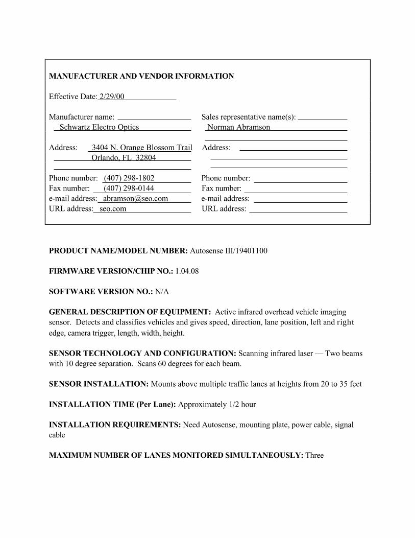
MANUFACTURER AND VENDOR INFORMATION
Effective Date: 2/29/00
Manufacturer name: Sales representative name(s):
Schwartz Electro Optics Norman Abramson
Address: 3404 N. Orange Blossom Trail Address:
Orlando, FL 32804
Phone number: (407) 298-1802 Phone number:
Fax number: (407) 298-0144 Fax number:
e-mail address: [email protected] e-mail address:
URL address: seo.com URL address:
PRODUCT NAME/MODEL NUMBER: Autosense III/19401100
FIRMWARE VERSION/CHIP NO.: 1.04.08
SOFTWARE VERSION NO.: N/A
GENERAL DESCRIPTION OF EQUIPMENT: Active infrared overhead vehicle imaging
sensor. Detects and classifies vehicles and gives speed, direction, lane position, left and rightedge, camera trigger, length, width, height.
SENSOR TECHNOLOGY AND CONFIGURATION: Scanning infrared laser — Two beams
with 10 degree separation. Scans 60 degrees for each beam.
SENSOR INSTALLATION: Mounts above multiple traffic lanes at heights from 20 to 35 feet
INSTALLATION TIME (Per Lane): Approximately 1/2 hour
INSTALLATION REQUIREMENTS: Need Autosense, mounting plate, power cable, signal
cable
MAXIMUM NUMBER OF LANES MONITORED SIMULTANEOUSLY: Three

PRODUCT CAPABILITIES/FUNCTIONS:Scan rate: 720 scans/sec
Field of regard: 80 degrees
Measures per scan: 90
Scanline separation: 10 degrees
Pixel resolution: 0.67 degrees
Detection Accuracy: 99.99%
Classification Accuracy 99%
Lane position accuracy: 0.67 degrees
RECOMMENDED APPLICATIONS: Multi-lane toll collection, traffic flow measurement,
routing studies, traffic monitoring
POWER REQUIREMENTS (watts/amps): 40 watts (160 watts with heaters on)
POWER OPTIONS: 115 VAC or 230 VAC (50 — 60 Hz)
CLASSIFICATION ALGORITHMS: Based on length, width, height and vehicle shape
TELEMETRY: RS-422 (RS 232 optional) serial interface at 19.2, 38.4, or 57.6 K band or
1Mbps
COMPUTER REQUIREMENTS: 166 MHz, 486 or better
DATA OUTPUT: Five data messages in normal mode or range and intensity in high speed mode
DATA OUTPUT FORMATS:
SUPPORTING DATA BASE MANAGEMENT SYSTEM: N/A
EQUIPMENT AND INSTALLATION COSTS (One-lane and four-lane):
STATES CURRENTLY USING THIS EQUIPMENT:
Country/State Contact name Telephone numberUSA/Florida Haitham Al-Deck (407) 823-2988
The Netherlands Rune Lende 011-47-905-59-406

MANUFACTURER AND VENDOR INFORMATION
Effective Date: 2/29/00
Manufacturer name: Sales representative name(s):
Schwartz Electro Optics Norman Abramson
Address: 3404 N. Orange Blossom Trail Address:
Orlando, FL 32804
Phone number: (407) 298-1802 Phone number:
Fax number: (407) 298-0144 Fax number:
e-mail address: [email protected] e-mail address:
URL address: seo.com URL address:
PRODUCT NAME/MODEL NUMBER: Autosense II/1947100
FIRMWARE VERSION/CHIP NO.: 1.01.XX (Depends on application)
SOFTWARE VERSION NO.: N/A
GENERAL DESCRIPTION OF EQUIPMENT: Active infrared overhead vehicle imaging
sensor. Detects and classifies vehicles and gives speed, direction, lane position, left and right
edge, camera trigger, length, width, height.
SENSOR TECHNOLOGY AND CONFIGURATION: Scanning infrared laser-two beams
with 10 degree separation. Scans 30 degrees for each beam.
SENSOR INSTALLATION: Mounts above center of traffic lane at heights ranging from 20 to
25 feet.
INSTALLATION TIME (Per Lane): Approximately 1 hour
INSTALLATION REQUIREMENTS: Need Autosense, mounting plate, power cable, and
signal cable
MAXIMUM NUMBER OF LANES MONITORED SIMULTANEOUSLY: One

PRODUCT CAPABILITIES/FUNCTIONS:Scan rate: 720 scans/sec; Field of Regard: 30 degrees; Measurements/scan: 30
Scanline separation: 10 degrees; Pixel resolution: 1 degree; Range Accuracy: 3
Detection Accuracy 99.99%
Classification Accuracy: 99%
Lane Position Accuracy: 1 degree
RECOMMENDED APPLICATIONS: Electronic toll collection, traffic management,
bridge/tunnel clearance, traffic studies, traffic mounting
POWER REQUIREMENTS (watts/amps): 35 watts (140 watts with heater on)
POWER OPTIONS: 115 VAC or 230 VAC, 50-60 Hz
CLASSIFICATION ALGORITHMS: Based on vehicle length, width, height, and shape.
TELEMETRY: RS-422 (RS 232 optional) serial interface at 129.2, 38.4 or 57.6 K or 1 Mbps
raw range and intensity data
COMPUTER REQUIREMENTS: 116 MHz, 486 or better
DATA OUTPUT: Five data messages in normal mode or range and intensity in high-speed mode.
DATA OUTPUT FORMATS:
SUPPORTING DATA BASE MANAGEMENT SYSTEM: N/A
EQUIPMENT AND INSTALLATION COSTS (One-lane and four-lane):
STATES CURRENTLY USING THIS EQUIPMENT:
Country/State Contact name Telephone numberCanada/Ontario A.J. Mohenred (905) 265-1733
USA/Florida Doug Martin (805) 488-5687
USA/Colorado Amos Pace (609) 235-5252
USA/New York Joe Lipari (732) 287-8585
USA/California Sialele Malope (658) 646-4200
South Korea Yang-Jong Park 011-02-531-8704
Italy Stefano Zoppi 011-39-55-420-2322

MANUFACTURER AND VENDOR INFORMATION
Effective Date: 2/29/00
Manufacturer name: Sales representative name(s):
Schwartz Electro Optics Norman Abramson
Address: 3404 N. Orange Blossom Trail Address:
Orlando, FL 32804
Phone number: (407) 298-1802 Phone number:
Fax number: (407) 298-0144 Fax number:
e-mail address: [email protected] e-mail address:
URL address: seo.com URL address:
PRODUCT NAME/MODEL NUMBER: Trafficsense
FIRMWARE VERSION/CHIP NO.: N/A
SOFTWARE VERSION NO.:
GENERAL DESCRIPTION OF EQUIPMENT: Advanced traffic data collection system.
Collects traffic data on single and multi-lane highways. Data includes number of vehicles, vehicle
class, speed, lane occupancy, headway.
SENSOR TECHNOLOGY AND CONFIGURATION: Scanning infrared laser sensors, data
logging computer with wireless modem that connects to the internet
SENSOR INSTALLATION: Sensors mount above traffic lanes at heights from 20 to 35 feet.
Computer and modem mount beside traffic lanes in a NEMA enclosure
INSTALLATION TIME (Per Lane): Approximately 2 hours
INSTALLATION REQUIREMENTS: Need Autosense sensors, mounting plates, signal cables,
power cables, computer, wireless modem, NEMA enclosure
MAXIMUM NUMBER OF LANES MONITORED SIMULTANEOUSLY: Three

PRODUCT CAPABILITIES/FUNCTIONS:Vehicle Detection Accuracy: 99.9%
Vehicle Classification Accuracy: 99%
Speed Accurcacy: 1 mph at 60 mph
RECOMMENDED APPLICATIONS: Traffic management, traffic monitoring, traffic studies
POWER REQUIREMENTS (watts/amps):Sensors: 40 watts ead (180 watts with heaters)
Computer and modem: 150 watts
POWER OPTIONS: 115 VAC (230 VAC optional) 50-60 Hz
CLASSIFICATION ALGORITHMS: Eleven vehicle classes based on vehicle length, width,
height shape
TELEMETRY: RS-422 from sensors to computers. Web browsing software with access
COMPUTER REQUIREMENTS: 166 MHz, Pentium or better
DATA OUTPUT: Data files for each day. Data summarized at 30 second intervals. Files can be
down loaded over internet. Real time traffic data display
DATA OUTPUT FORMATS: Binary data files
SUPPORTING DATA BASE MANAGEMENT SYSTEM: Excel spreadsheet for display and
graphing of data
EQUIPMENT AND INSTALLATION COSTS (One-lane and four-lane):
STATES CURRENTLY USING THIS EQUIPMENT:
Country/State Contact name Telephone numberUSA/Florida Haitham Al-Deek (407) 823-2988

MANUFACTURER AND VENDOR INFORMATION
Effective Date: 20 March 2000
Manufacturer name: Sales representative name(s):
Infrared Technologies Carlos Ghigliotty
Address: Address:
608 Washington Blvd., Suite 304 608 Washington Blvd., Suite 304
Laurel, MD 20707 Laurel, MD 20707
Phone number: (301) 470-4055 Phone number: (301) 470-4055
Fax number: Fax number: (301) 470-4055
e-mail address: e-mail address
URL address: URL address:
PRODUCT NAME/MODEL NUMBER: Video mapping system
FIRMWARE VERSION/CHIP NO.: N/A
SOFTWARE VERSION NO.: N/A
GENERAL DESCRIPTION OF EQUIPMENT:
SENSOR TECHNOLOGY AND CONFIGURATION: Infrared/visible low light cameras
integrated into a mapping system
SENSOR INSTALLATION: Inside the light bar or inside the car
INSTALLATION TIME (Per Lane): N/A
INSTALLATION REQUIREMENTS:.N/A
MAXIMUM NUMBER OF LANES MONITORED SIMULTANEOUSLY: Two
PRODUCT CAPABILITIES/FUNCTIONS: See literature
RECOMMENDED APPLICATIONS:

POWER REQUIREMENTS (watts/amps): 12V 20 watts
POWER OPTIONS: N/A
CLASSIFICATION ALGORITHMS: N/A
TELEMETRY: Available
COMPUTER REQUIREMENTS: P2 450
DATA OUTPUT: Video RS170 GPS Data
DATA OUTPUT FORMATS: 66A + TV6
RS120 or NTSC
SUPPORTING DATA BASE MANAGEMENT SYSTEM: N/A
EQUIPMENT AND INSTALLATION COSTS (One-lane and four-lane): N/A
STATES CURRENTLY USING THIS EQUIPMENT:
Country/State Contact name Telephone number
CONTACT INFRARED TECHNOLOGIES FOR CURRENT LIST OF REFERENCES.
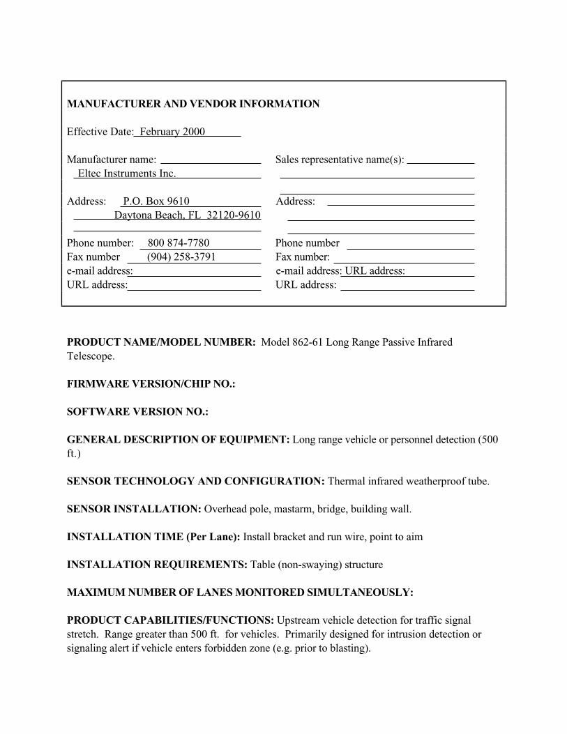
MANUFACTURER AND VENDOR INFORMATION
Effective Date: February 2000
Manufacturer name: Sales representative name(s):
Eltec Instruments Inc.
Address: P.O. Box 9610 Address:
Daytona Beach, FL 32120-9610
Phone number: 800 874-7780 Phone number
Fax number (904) 258-3791 Fax number:
e-mail address: e-mail address: URL address:
URL address: URL address:
PRODUCT NAME/MODEL NUMBER: Model 862-61 Long Range Passive Infrared
Telescope.
FIRMWARE VERSION/CHIP NO.:
SOFTWARE VERSION NO.:
GENERAL DESCRIPTION OF EQUIPMENT: Long range vehicle or personnel detection (500
ft.)
SENSOR TECHNOLOGY AND CONFIGURATION: Thermal infrared weatherproof tube.
SENSOR INSTALLATION: Overhead pole, mastarm, bridge, building wall.
INSTALLATION TIME (Per Lane): Install bracket and run wire, point to aim
INSTALLATION REQUIREMENTS: Table (non-swaying) structure
MAXIMUM NUMBER OF LANES MONITORED SIMULTANEOUSLY:
PRODUCT CAPABILITIES/FUNCTIONS: Upstream vehicle detection for traffic signal
stretch. Range greater than 500 ft. for vehicles. Primarily designed for intrusion detection or
signaling alert if vehicle enters forbidden zone (e.g. prior to blasting).

RECOMMENDED APPLICATIONS: Signal control at temporary construction sites,
temporary replacement of failed lop detectors, side street demand only signal control.
POWER REQUIREMENTS (watts/amps): 10.5 to 28 VDC @ 75 MA max
POWER OPTIONS:
CLASSIFICATION ALGORITHMS:
TELEMETRY:
COMPUTER REQUIREMENTS:
DATA OUTPUT: Presence
DATA OUTPUT FORMATS:
SUPPORTING DATA BASE MANAGEMENT SYSTEM:
EQUIPMENT AND INSTALLATION COSTS (One-lane and four-lane):
STATES CURRENTLY USING THIS EQUIPMENT:
Country/State Contact name Telephone number
CONTACT ELTEC INSTRUMENTS FOR COMPLETE LIST OF REFERENCES.

MANUFACTURER AND VENDOR INFORMATION
Effective Date: January 2000
Manufacturer name: Sales representative name(s):
Eltec Instruments Inc.
Address: P.O. Box 9610 Address:
Daytona Beach, FL 32120-9610
Phone number: 800 874-7780 Phone number
Fax number (904) 258-3791 Fax number:
e-mail address: e-mail address:
URL address: URL address:
PRODUCT NAME/MODEL NUMBER: Model 833 Passive Infrared Traffic Monitor
FIRMWARE VERSION/CHIP NO.:
SOFTWARE VERSION NO.:
GENERAL DESCRIPTION OF EQUIPMENT: Small optical vehicle detector
SENSOR TECHNOLOGY AND CONFIGURATION: Thermal infrared moving vehicle
detector in weatherproof aluminum case.
SENSOR INSTALLATION: Overhead/pole or mast arm mount or bridge.
INSTALLATION TIME (Per Lane): Attach bracket and run wire
INSTALLATION REQUIREMENTS: Pole or mastarm
MAXIMUM NUMBER OF LANES MONITORED SIMULTANEOUSLY: One
PRODUCT CAPABILITIES/FUNCTIONS: Traffic counting at highway or city speeds. Will
not interfere with any other equipment (totally passive).
RECOMMENDED APPLICATIONS: Highway vehicle counting

POWER REQUIREMENTS (watts/amps): 115 VAC @ 2W max
POWER OPTIONS: 230 VAC @ 2W or 12VDC @ 22 MA max
CLASSIFICATION ALGORITHMS:
TELEMETRY:
COMPUTER REQUIREMENTS:
DATA OUTPUT: Presence
DATA OUTPUT FORMATS:
SUPPORTING DATA BASE MANAGEMENT SYSTEM:
EQUIPMENT AND INSTALLATION COSTS (One-lane and four-lane):
STATES CURRENTLY USING THIS EQUIPMENT:
Country/State Contact name Telephone number
CONTACT ELTEC INSTRUMENTS FOR CURRENT LIST OF REFERENCES.

MANUFACTURER AND VENDOR INFORMATION
Effective Date: January 2000
Manufacturer name: Sales representative name(s):
Eltec Instruments Inc.
Address: P.O. Box 9610 Address:
Daytona Beach, FL 32120-9610
Phone number: 800 874-7780 Phone number
Fax number (904) 258-3791 Fax number:
e-mail address: e-mail address
URL address: URL address:
PRODUCT NAME/MODEL NUMBER: Model 842 Overhead Vehicle Presence Sensor
FIRMWARE VERSION/CHIP NO.:
SOFTWARE VERSION NO.:
GENERAL DESCRIPTION OF EQUIPMENT: Small, self-contained optical (mount and aim)
sensor with relay output for vehicle presence detection.
SENSOR TECHNOLOGY AND CONFIGURATION: Passive thermal infrared sensor
technology, overhead mount (pole/mast arm) configuration.
SENSOR INSTALLATION: Overhead/pole or mast arm mount, aimed at lane to be monitored.
INSTALLATION TIME (Per Lane): Attach bracket and run wire
INSTALLATION REQUIREMENTS: Pole or mastarm
MAXIMUM NUMBER OF LANES MONITORED SIMULTANEOUSLY: One lane (ideal)
PRODUCT CAPABILITIES/FUNCTIONS: Vehicle presence sensor with relay output.
(Multiple units at installation will not interfere with each other; device operation cannot interfere
with radios or other electronic equipment).

RECOMMENDED APPLICATIONS: Signal control at temporary construction sites,
temporary replacement of failed lop detectors, side street demand only signal control.
POWER REQUIREMENTS (watts/amps): 10.0 watts max. @120 VAC
POWER OPTIONS: 240 VAC, optional
CLASSIFICATION ALGORITHMS: N/A
TELEMETRY: N/A
COMPUTER REQUIREMENTS: N/A
DATA OUTPUT:
DATA OUTPUT FORMATS:
SUPPORTING DATA BASE MANAGEMENT SYSTEM:
EQUIPMENT AND INSTALLATION COSTS (One-lane and four-lane):
STATES CURRENTLY USING THIS EQUIPMENT:
Country/State Contact name Telephone numberUSA/Florida
USA/California
USA/North Carolina


5-22
Ultrasonic Sensors
Principles of Operation
Ultrasonic sensors transmit pressure waves of sound energy at a frequency between 25 and 50
KHz, which are above the human audible range. Most ultrasonic sensors, such as the model
shown in Figure 29, operate with pulse waveforms and provide vehicle count, presence, and
occupancy information. Pulse waveforms measure distances to the road surface and vehicle
surface by detecting the portion of the transmitted energy that is reflected towards the sensor
from an area defined by the transmitter s beamwidth. When a distance other than that to the
background road surface is measured, the sensor interprets that measurement as the presence of a
vehicle. The received ultrasonic energy is converted into electrical energy that is analyzed by
signal processing electronics that is either collocated with the transducer or placed in a roadside
controller.
Figure 29. TC-30C ultrasonic range-measuring sensor. (Photograph courtesy ofMicrowave Sensors, Ann Arbor, MI).
Application and Uses
Pulse energy transmitted at two known and closely spaced incident angles allows vehicular speed
to be calculated by recording the time at which the vehicle crosses each beam. Since the beams
are a known distance apart, the speed is given by Eq. (6). Constant frequency ultrasonic sensors

5-23
that measure speed using the Doppler principle are also manufactured. However, these are more
expensive than pulse models.
The preferred mounting configurations for range-measuring, pulsed ultrasonic sensors are
downward looking and side viewing as shown in Figure 30. The range-measuring ultrasonic
sensor transmits a series of pulses of width Tp (typical values are between 0.02 and 2.5 ms) and
repetition period T0 (time between bursts of pulses), typically 33 to 170 ms. The sensor
measures the time it takes for the pulse to arrive at the vehicle and return to the transmitter. The
receiver is gated on and off with a user-adjustable interval that helps to differentiate between
pulses reflected from the road surface and those reflected from vehicles. The detection gate is
adjusted to detect an object at a distance greater than approximately 0.5 m above the road surface.
Automatic pulse-repetition frequency control reduces effects of multiple reflections and
improves the detection of high-speed vehicles. This control is implemented by making the pulse
repetition period as short as possible by transmitting the next pulse immediately after the
reflected signal from the road is received (Kumagai, et al., 1992). A hold time Th (composite
values from manufacturers range from 115 ms to 10 s) is built into the sensors to enhance
presence detection.
Advantages
Installation of ultrasonic sensors does not require an invasive pavement procedure. Also, some
models feature multiple lane operation.

5-24
Figure 30. Mounting of ultrasonic range-measuring sensors. (Courtesy ofMicrowave Sensors, Ann Arbor, MI).
Disadvantages
Temperature change and extreme air turbulence may affect the performance of ultrasonic sensors.
Temperature compensation is built into some models. Large pulse repetition periods may
degrade occupancy measurement on freeways with vehicles traveling at moderate to high speeds.

MANUFACTURER AND VENDOR INFORMATION
Effective Date: 2/29/00
Manufacturer name: Sales representative name(s):
Sumitomo Electric. Takehiko Barada
Address: 1-1-3 Shimaya Address: 3235 Kifer Road
Konohana-ku, Osaka 554-0024 Suite 150
Japan Santa Clara, CA 95051
Phone number: +81 6-6461-1031 Phone number: (408) 737-8517
Fax number: +81 6-6466-3305 Fax number: (408) 737-0134
e-mail address: [email protected] e-mail address: [email protected]
URL address: www.sel.co.jp URL address: www.sumitomo.com/its/
PRODUCT NAME/MODEL NUMBER: SDU-420
FIRMWARE VERSION/CHIP NO.: N/A
SOFTWARE VERSION NO.: N/A
GENERAL DESCRIPTION OF EQUIPMENT: Ultrasonic Vehicle Detector
SENSOR TECHNOLOGY AND CONFIGURATION: Ultrasound
SENSOR INSTALLATION: Overhead
INSTALLATION TIME (Per Lane):
INSTALLATION REQUIREMENTS: Pole arm
MAXIMUM NUMBER OF LANES MONITORED SIMULTANEOUSLY: One lane/head
PRODUCT CAPABILITIES/FUNCTIONS: Presence, occupancy, classification (two)
RECOMMENDED APPLICATIONS: Advanced traffic signal control, freeway monitoring,

POWER REQUIREMENTS (watts/amps): 160 va
POWER OPTIONS: N/A
CLASSIFICATION ALGORITHMS: Vehicle height
TELEMETRY: N/A
COMPUTER REQUIREMENTS: NO
DATA OUTPUT: NEMA TS1, custom
DATA OUTPUT FORMATS: N/A
SUPPORTING DATA BASE MANAGEMENT SYSTEM: N/A
EQUIPMENT AND INSTALLATION COSTS (One-lane and four-lane):Approx. $1,900/one lane & installation cost
STATES CURRENTLY USING THIS EQUIPMENT:
Country/State Contact name Telephone numberJapan

5-25
Passive Acoustic Array Sensors
Acoustic sensors measure vehicle passage, presence, and speed by detecting acoustic energy or
audible sounds produced by vehicular traffic from a variety of sources within each vehicle and
from the interaction of a vehicle s tires with the road. When a vehicle passes through the
detection zone, an increase in sound energy is recognized by the signal-processing algorithm and a
vehicle presence signal is generated. When the vehicle leaves the detection zone, the sound
energy level drops below the detection threshold and the vehicle presence signal is terminated.
Sounds from locations outside the detection zone are attenuated.
Principles of Operation
Two models of acoustic sensors are marketed. Both detect the sounds produced by approaching
vehicles with a two-dimensional array of microphones. The SmartSonic acoustic sensor shown
on the left in Figure 31 detects vehicles by measuring the time delay between the arrival of sound
at the upper and lower microphones, which are arranged in a vertical and horizontal line through
the center of the aperture. The time delay changes as the vehicle approaches the array. When the
vehicle is inside the detection zone, the sound arrives almost instantaneously at the upper and
lower microphones. When the vehicle is outside the detection zone, sound reception at the upper
microphone is delayed by the intermicrophone distance. The size and shape of the detection
zone are determined by the aperture size, processing frequency band, and installation geometry
of the acoustic array. The SmartSonic sensor is tuned to a center frequency of 9 KHz with a 2
KHz bandwidth. Preferred mounting is at 10 to 30 degrees from nadir with a detection range of
20 to 35 ft (6 to 11 m).
Application and Uses
The speed of a detected vehicle is determined with an algorithm that assumes an average vehicle
length. Vehicle presence detection is through an optically isolated semiconductor. When the
optional acoustic sensor controller board is installed in a NEMA or 170 cardfile, two detection

5-26
zones can be used in a speed trap mode to measure vehicle speed. The speed trap activates relay
outputs that simulate two inductive loops connected to a NEMA or 170 controller. The
SmartSonic is recommended for data collection applications on bridges and other roads where
non-intrusive sensors are required and where slow moving vehicles in stop and go traffic flow are
not present.
The SAS-1 acoustic sensor on the right in Figure 31 uses a fully populated microphone array and
adaptive spatial processing to form multiple zones that receive the acoustic energy from up to 6
to 7 lanes when the sensor is mounted over the center of the roadway. Five lanes are the
practical limit for the side-mounting configuration. During setup, the detection zones are steered
to positions that correspond to the monitored traffic lanes. The detection zones are self
normalized and polled for vehicles every 8 minutes. The detection zone is equivalent to that of a
6-ft inductive loop in the direction of traffic flow and is user selectable in the cross-lane direction.
Figure 31. Acoustic array sensors.
SAS-1 acoustic sensor. (Photographcourtesy of SmarTek Systems, Woodbridge,VA)
SmartSonic acoustic sensor.(Photograph courtesy of IRD,Saskatoon, SK)

5-27
Acoustic frequencies between 8 and 15 KHz are processed by this sensor, which accommodates
mounting heights between 20 and 40 ft (6 to 12 m). The output data are volume, lane occupancy,
and average speed for each monitored lane over a user-specified period (e.g., 20s, 30s, 1 min).
Vehicle presence is provided by an optional relay interface.
Advantages
Installation of passive acoustic array sensors does not require and invasive pavement procedure.
Acoustic sensors are insensitive to precipitation and multiple lane operation is available in some
models.
Disadvantages
Cold temperatures have been reported as affecting the accuracy of the data from acoustic sensors.
Also, specific models are not recommended with slow moving vehicles in stop and go traffic.

MANUFACTURER AND VENDOR INFORMATION
Effective Date:March 22, 2000
Manufacturer name: International Road Sales representative name(s): Rod Klashinsky
Dynamics, Inc.
Address: 702 43rd
Street East Address:
Saskatoon SK, S7K 3T9 Canada
Phone number: 306-653-6600 Phone number:
Fax number: 306-242-5599 Fax number:
e-mail address: [email protected] e-mail address:
URL address: www.irdinc.com URL address:
PRODUCT NAME/MODEL NUMBER: IRD SmartSonicTM
Vehicle Detection System
FIRMWARE VERSION/CHIP NO.: NA
SOFTWARE VERSION NO.: NA
GENERAL DESCRIPTION OF EQUIPMENT: The IRD SmartsonicTM
Vehicle Detection
System is based on acoustic-sensing and signal processing technologies. The SmartSonicTM
sensors are mounted non-intrusively above or beside roadways on existing structures such as
bridges, overhead traffic signs or light poles. Structures may be installed specifically to mount
the sensors if required. IRD SmartSonicTM
Vehicle Detection Systems are ideal for detection of
vehicles on roadways where lane closure is not an option.
SENSOR TECHNOLOGY AND CONFIGURATION: SmartSonicTM
detectors are acoustic-
sensing technology for vehicle detection. A single detector provides vehicle detection per lane.
SENSOR INSTALLATION: Sensors may be installed above or beside roadways using existing
structures or specifically installed structures.
INSTALLATION TIME (Per Lane): Typically 4 hours.
INSTALLATION REQUIREMENTS: Please see attached product information for details.

MAXIMUM NUMBER OF LANES MONITORED SIMULTANEOUSLY: Four (4)
SmartSonic“ sensors can interface to a single SmartSonicTM
controller to monitor 4 lanes.
PRODUCT CAPABILITIES/FUNCTIONS: Vehicle detection, Traffic counting, Occupancy
Counts per lane of Traffic.
RECOMMENDED APPLICATIONS: Vehicle detection, Traffic counting, Occupancy Counts
per lane of traffic in free-flow traffic at speeds of more than 30 MPH.
POWER REQUIREMENTS (watts/amps): 12-24 VDC
POWER OPTIONS: DC or solar.
CLASSIFICATION ALGORITHMS: Up to 3 classes.
TELEMETRY: Yes
COMPUTER REQUIREMENTS: A laptop computer may be used for information retrieval
with serial communication software such as HyperTerminal.
DATA OUTPUT: Serial or contact closure.
DATA OUTPUT FORMATS: ASCII
SUPPORTING DATA BASE MANAGEMENT SYSTEM: NA
EQUIPMENT AND INSTALLATION COSTS (One-lane and four-lane):1-lane: $ 4,000 US
4-lane: $ 12,000 US
STATES CURRENTLY USING THIS EQUIPMENT:
Country/State Contact name Telephone numberUSA/Massachusetts
USA/Texas
USA/Arizona

MANUFACTURER AND VENDOR INFORMATION
Effective Date: August 1, 2000
Manufacturer name: SmarTek Systems Sales representative name(s):
Greg Pieper
Address: 14710 Kogan Drive Address: 295 Waycross Way
Woodbridge, VA 22193 Arnold, MD 21072
Phone number: (703) 680-6554 Phone number: (410) 315-9727
Fax number: Fax number: (410) 384-9264
e-mail address: e-mail address: [email protected]
URL address: URL address: www.smarteksys.com
PRODUCT NAME/MODEL NUMBER: SAS-1
FIRMWARE VERSION/CHIP NO.:
SOFTWARE VERSION NO.: Revision 20
GENERAL DESCRIPTION OF EQUIPMENT: A passive acoustic, multilane, side fire vehicle
detector/counter
SENSOR TECHNOLOGY AND CONFIGURATION: Passive acoustic
SENSOR INSTALLATION: Side Fire
INSTALLATION TIME (Per Lane): 5 minutes
INSTALLATION REQUIREMENTS: Pole mount; bucket truck
MAXIMUM NUMBER OF LANES MONITORED SIMULTANEOUSLY: Five
PRODUCT CAPABILITIES/FUNCTIONS: True presence, traffic count (volume), speed
(average and per vehicle), lane occupancy, 15 — 60 day data storage (dependent on memory
version)
RECOMMENDED APPLICATIONS: Traffic monitoring of highways, etc

POWER REQUIREMENTS (watts/amps):
POWER OPTIONS:
CLASSIFICATION ALGORITHMS:
TELEMETRY:
COMPUTER REQUIREMENTS:
DATA OUTPUT: See capabilities/functions
DATA OUTPUT FORMATS:
SUPPORTING DATA BASE MANAGEMENT SYSTEM:
EQUIPMENT AND INSTALLATION COSTS (One-lane and four-lane):
STATES CURRENTLY USING THIS EQUIPMENT:
Country/State Contact name Telephone numberUSA/Arizona Tim Wolf (602) 712-6622
USA/Arizona Glenn Jonas (602) 712-6587
USA/California Edward Fok (213) 485-8609
USA/Idaho Jim Larsen (208) 387-6197
USA/Virginia Cyndi Ward (804) 692-0390
USA/Virginia Mr. Stephany Hanshaw (757) 464-9907
USA/New York Bill Platt (607) 324-8412


6-1
Chapter 6 - References
Apogee/Hagler Bailly, Intelligent Transportation Systems: Real World Benefits, FHWA-JPO-98-
018, January 1998.
ASTM E1318-94, Standard Specification for Highway Weigh-in-Motion (WIM) with UserRequirements and Test Method, Annual Book of ASTM Standards, vol. 04.03, West
Conshohocken, PA, 1994.
Caldera, R., Long-Term Stable Quartz WIM Sensors, Proceedings — National Traffic DataAcquisition Conference, Vol. II, NM-NATDAC 96, Albuquerque, NM, May 5-6, 1996, NM
State Highway and Transportation Dept., Santa Fe, NM.
Castle Rock Consultants, Automated Traffic/Truck Weight Monitoring Equipment (Weigh-in-Motion), FHWA-DP-88-76-006, May 1988.
Chang, E. C-P and H. Kunhuang, Incident Detection Using Advanced Technologies, Paper
930943, 72nd
Annual Meeting, Transportation Research Board, Washington, D.C., 1993.
Fowler, D. W., Selection of Bonding Materials for Piezoelectric Sensors, Proceedings — NationalTraffic Data Acquisition Conference, Vol. II, NM-NATDAC 96, Albuquerque, NM, May 5-
6, 1996, NM State Highway and Transportation Dept., Santa Fe, NM.
Gordon, R.L., R.A. Reiss, H. Haenel, E.R. Case, R.L. French, A. Mohaddes, and R. Wolcott,
Traffic Control Systems Handbook, FHWA-SA-95-032, Federal Highway Administration,
U.S. Department of Transportation, Washington, D.C., Feb. 1996.
Halvorsen, Don, Finger on the Pulse — Piezos on the Rise, Traffic Technology International,
June/July, 1999.
Hockaday, S., Evaluation of Image Processing Technology for Applications in HighwayOperations Final Report, TR 91-2, Transportation Res. Group, California Polytechnical State
University, San Luis Obispo, California, Jun. 29, 1991.
JAMAR Technologies, Inc., Catalog Number 7, Horsham, PA.
Kell, J.H. and I.J. Fullerton, Traffic Detector Handbook, Second Edition, U.S. Department of
Transportation, Federal Highway Administration, Washington, D.C., 1990.
Kistler Instrumente AG, Weigh In Motion: The First System for Monitoring at Any Speed,
Winterthur, Switzerland, October 1997.

6-2
Klein L. A. and M.R. Kelley, Detection Technology for IVHS, Vol. I: Final Report, FHWA-RD-
95-100, Federal Highway Administration, U.S. Department of Transportation, Washington,
D.C., Dec. 1996.
Klein, L. A., Millimeter-Wave and Infrared Multisensor Design and Signal Processing, Artech
House, Norwood, MA, 1997.
Klein, L. A., Final Report: Mobile Surveillance and Wireless Communication Systems FieldOperational Test - Vol. 1: Executive Summary, California PATH Res. Rpt. UCB-ITS-PRR-
99-6, University of California, Berkeley, Richmond, CA, Mar. 1999.
Klein, L. A., Final Report: Mobile Surveillance and Wireless Communication Systems FieldOperational Test - Vol. 2: FOT Objectives, Organization, System Design, Results,Conclusions, and Recommendations, California PATH Res. Rpt. UCB-ITS-PRR-99-7,
University of California, Berkeley, Richmond, CA, Mar. 1999.
Klein, L. A., Data Requirements and Sensor Technologies for ITS, Norwood, MA, Artech
House, 2001.
Kranig J., E. Minge, and C. Jones, Field Test of Monitoring of Urban Vehicle Operations UsingNon-Intrusive Technologies, FHWA-PL-97-018, Federal Highway Administration, U.S.
Department of Transportation, Washington, D.C., May 1997.
Kumagai, Y., T. Yamamoto, M. Deguchi, and S. Yamaoka, Ultrasonic Detector and New TypeSensors for Urban Traffic Control Systems, Sumitomo Electric Industries, 1992.
Lenz, J.E., FAA Demonstration of Alternate Technologies to Prevent Runway Incursions, Final
Rpt. Vol. 1, Honeywell Inc., Systems and Research Center, Minneapolis, MN, Apr. 1993.
McCall, William, Vodrazka, Walt, Center for Transportation Research and Education, Iowa State
University, States Best Practices Weigh-In-Motion Handbook,
http://www.ctre.iastate.edu/research/wim_pdf/index.htm
MacCarley, C.A., S. Hockaday, D. Need, S. Taff, Evaluation of Video Image Processing
Systems for Traffic Detection, Transportation Research Record No. 1360, National
Research Council, Washington D.C., 1992.
Michalopoulos, P.G., R.D. Jacobson, C.A. Anderson, and J.C. Barbaresso, Integration of
Machine Vision and Adaptive Control in the Fast-Trac IVHS Program, 72nd
Annual
Meeting, Transportation Research Board, Washington, D.C., Jan. 1993.

6-3
Nestor Corp. Data Sheets, Providence, R.I., 1999.
Proper, Allen T., Cheslow, Melvyn D., ITS Benefits: Continuing Successes and Operational TestResults, FHWA-JPO-98-002, October 1997.
Roadtrax, Roadtrax BL and BLC Piezoelectric Sensor Catalog Sheets, Amp Inc., Valley Forge,
PA, March 1995 and April 1996. Catalogs also available from Measurement Specialties,
Norristown, PA, 1998.
Sampey, H.R., Vehicle Magnetic Imaging, Nu-Metrics, Vanderbilt, PA, May 1994.
News, Oct. 6, 1999, p.4.
Wentworth, J., C. Dougan, D. Green, W. Kaufman, E. Kent, T. O Keefe, and H. Wang,
International Scanning Report on Advanced Transportation Technology, Federal Highway
Administration, FHWA-PL-95-027, Washington, D.C., Dec. 1994.


Appendix - A
APPENDIX A (hardcopy only):
Vendor/Manufacturer Database
Vendor Survey (Blank)
Vendor Form Letter