Embed Size (px)
Citation preview
VDM® Alloy 825
Nicrofer 4221
Data Sheet No. 4101
August 2015
August 2015 VDM® Alloy 825 2
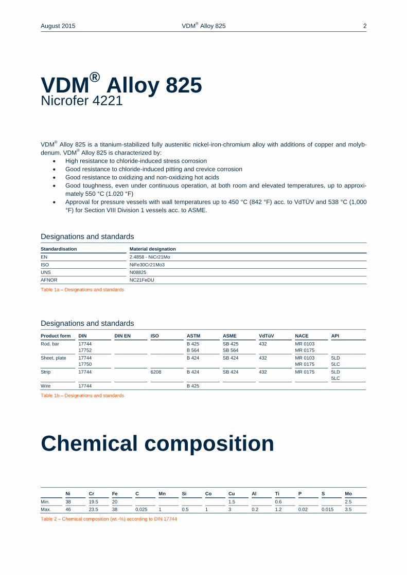
VDM® Alloy 825 is a titanium-stabilized fully austenitic nickel-iron-chromium alloy with additions of copper and molyb-
denum. VDM® Alloy 825 is characterized by:
High resistance to chloride-induced stress corrosion
Good resistance to chloride-induced pitting and crevice corrosion
Good resistance to oxidizing and non-oxidizing hot acids
Good toughness, even under continuous operation, at both room and elevated temperatures, up to approxi-
mately 550 °C (1.020 °F)
Approval for pressure vessels with wall temperatures up to 450 °C (842 °F) acc. to VdTÜV and 538 °C (1,000
°F) for Section VIII Division 1 vessels acc. to ASME.
Designations and standards
Standardisation Material designation
EN 2.4858 - NiCr21Mo
ISO NiFe30Cr21Mo3
UNS N08825
AFNOR NC21FeDU
Table 1a – Designations and standards
Designations and standards
Product form DIN DIN EN ISO ASTM ASME VdTüV NACE API
Rod, bar 17744
17752
B 425
B 564
SB 425
SB 564
432 MR 0103
MR 0175
Sheet, plate 17744
17750
B 424 SB 424 432 MR 0103
MR 0175
5LD
5LC
Strip 17744 6208 B 424 SB 424 432 MR 0175 5LD
5LC
Wire 17744 B 425
Table 1b – Designations and standards
Chemical composition
Ni Cr Fe C Mn Si Co Cu Al Ti P S Mo
Min. 38 19.5 20 1.5 0.6 2.5
Max. 46 23.5 38 0.025 1 0.5 1 3 0.2 1.2 0.02 0.015 3.5
Table 2 – Chemical composition (wt.-%) according to DIN 17744
VDM® Alloy 825
Nicrofer 4221
August 2015 VDM® Alloy 825 3
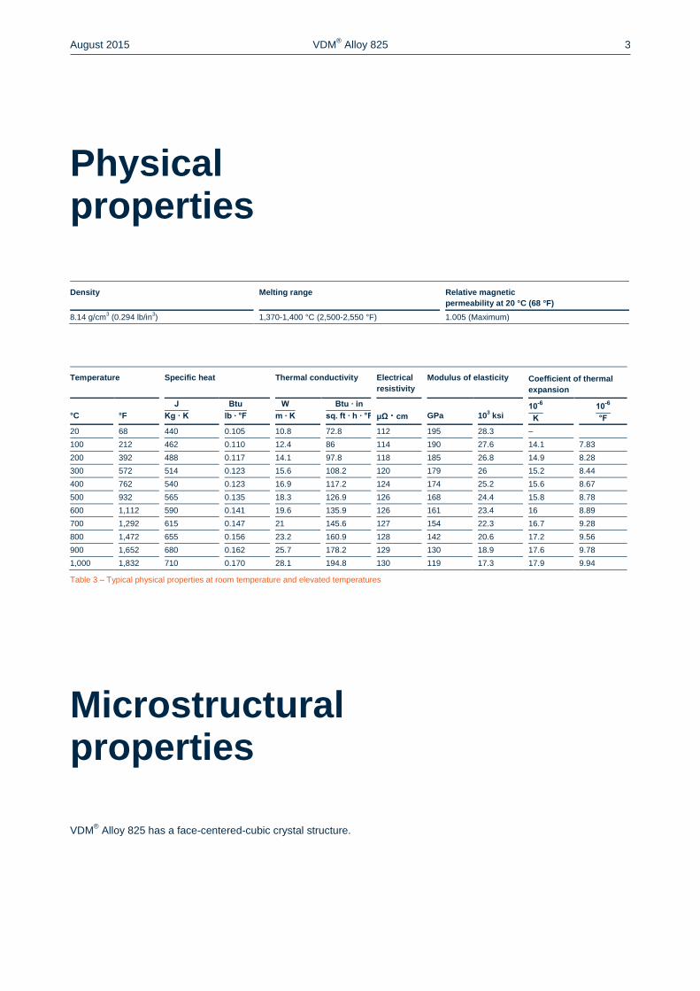
Physical properties
Density Melting range Relative magnetic
permeability at 20 °C (68 °F)
8.14 g/cm3 (0.294 lb/in
3) 1,370-1,400 °C (2,500-2,550 °F) 1.005 (Maximum)
Temperature Specific heat Thermal conductivity Electrical
resistivity
Modulus of elasticity Coefficient of thermal
expansion
°C
°F
μΩ · cm
GPa
103 ksi
20 68 440 0.105 10.8 72.8 112 195 28.3 –
100 212 462 0.110 12.4 86 114 190 27.6 14.1 7.83
200 392 488 0.117 14.1 97.8 118 185 26.8 14.9 8.28
300 572 514 0.123 15.6 108.2 120 179 26 15.2 8.44
400 762 540 0.123 16.9 117.2 124 174 25.2 15.6 8.67
500 932 565 0.135 18.3 126.9 126 168 24.4 15.8 8.78
600 1,112 590 0.141 19.6 135.9 126 161 23.4 16 8.89
700 1,292 615 0.147 21 145.6 127 154 22.3 16.7 9.28
800 1,472 655 0.156 23.2 160.9 128 142 20.6 17.2 9.56
900 1,652 680 0.162 25.7 178.2 129 130 18.9 17.6 9.78
1,000 1,832 710 0.170 28.1 194.8 130 119 17.3 17.9 9.94
Table 3 – Typical physical properties at room temperature and elevated temperatures
Microstructural properties
VDM® Alloy 825 has a face-centered-cubic crystal structure.
August 2015 VDM® Alloy 825 4
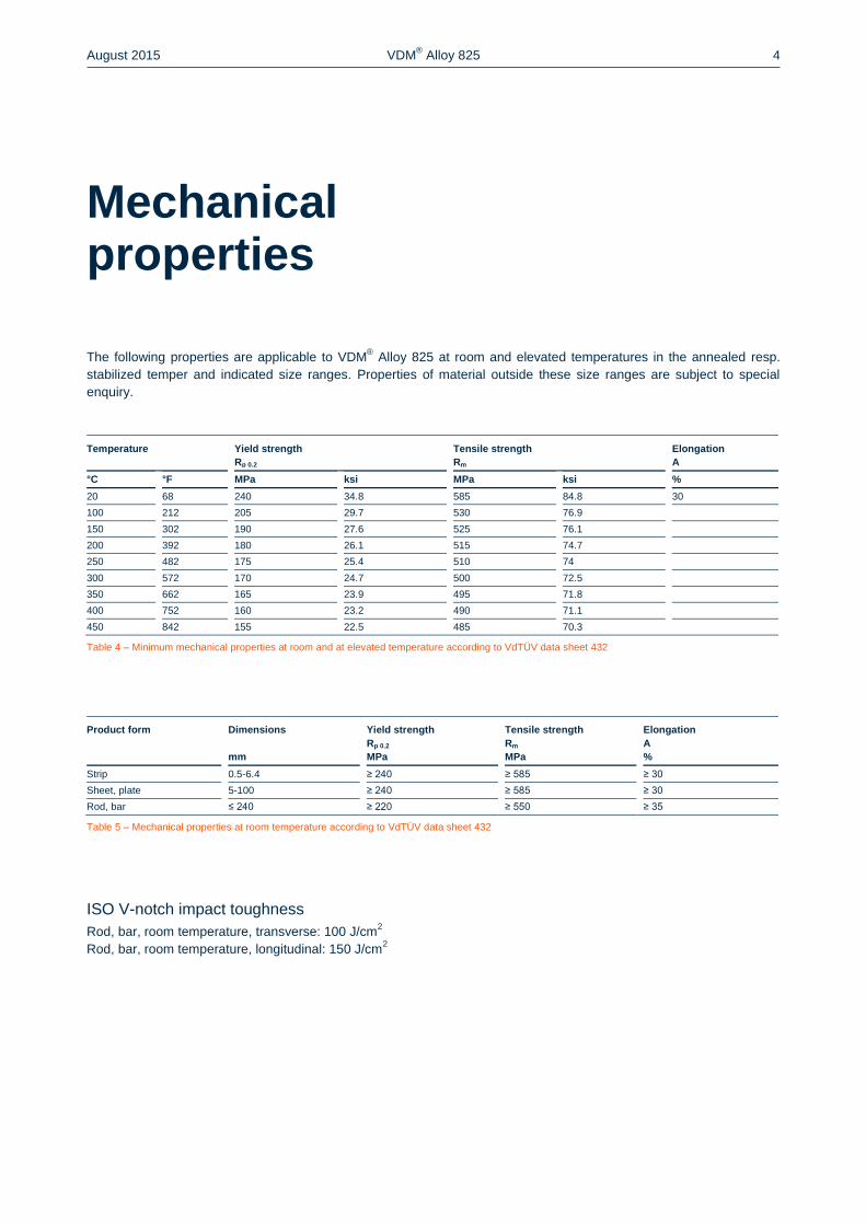
Mechanical properties
The following properties are applicable to VDM® Alloy 825 at room and elevated temperatures in the annealed resp.
stabilized temper and indicated size ranges. Properties of material outside these size ranges are subject to special
enquiry.
Temperature Yield strength
Rp 0.2
Tensile strength
Rm
Elongation
A
°C °F MPa ksi MPa ksi %
20 68 240 34.8 585 84.8 30
100 212 205 29.7 530 76.9
150 302 190 27.6 525 76.1
200 392 180 26.1 515 74.7
250 482 175 25.4 510 74
300 572 170 24.7 500 72.5
350 662 165 23.9 495 71.8
400 752 160 23.2 490 71.1
450 842 155 22.5 485 70.3
Table 4 – Minimum mechanical properties at room and at elevated temperature according to VdTÜV data sheet 432
Product form Dimensions
mm
Yield strength
Rp 0.2
MPa
Tensile strength
Rm
MPa
Elongation
A
%
Strip 0.5-6.4 ≥ 240 ≥ 585 ≥ 30
Sheet, plate 5-100 ≥ 240 ≥ 585 ≥ 30
Rod, bar ≤ 240 ≥ 220 ≥ 550 ≥ 35
Table 5 – Mechanical properties at room temperature according to VdTÜV data sheet 432
ISO V-notch impact toughness
Rod, bar, room temperature, transverse: 100 J/cm2
Rod, bar, room temperature, longitudinal: 150 J/cm2
August 2015 VDM® Alloy 825 5
Corrosion resistance
VDM® Alloy 825 is a versatile engineering alloy with resistance to corrosion in acids and alkalis under both oxidizing
and reducing conditions.
The high nickel content gives the alloy virtual immunity to stress corrosion cracking.
The corrosion resistance in various media like sulfuric, phosphoric, nitric and organic acids is good, as well as the cor-
rosion resistance in alkalis or ammoniac, sea water and caustic chloride.
The versatility of VDM® Alloy 825 is illustrated by its use in nuclear fuel element dissolvers where a variety of corrosive
media, e. g. sulfuric and nitric acids and sodium hydroxide, are handled in the same equipment.
Applications
VDM® Alloy 825 is used in the oil and gas industry and in a wide variety of chemical processes. Typical application
fields include:
Pipes, tubes and fittings in the oil and gas extraction, e. g. in heat exchangers, evaporators, washers, immer-
sion pipes in sea water cooled heat exchangers, offshore piping
Components in sulfuric acid pickling plants like heating coils, vessels, boilers, baskets and chains
Heat exchangers, evaporators, washers, immersion pipes in phosphoric acid production
Food industry
August 2015 VDM® Alloy 825 6
Fabrication and heat treatment
VDM® Alloy 825 can readily be hot- and cold-worked and machined.
Heating
Workpieces must be clean and free of any contaminants before and during heat treatment. Sulfur, phosphorus, lead
and other low-melting-point metals can lead to damages when heat treating VDM® Alloy 825. Sources of such contami-
nants include marking and temperature-indicating paints and crayons, lubricating grease and fluids, and fuels. Fuels
should contain as little sulfur as possible. Natural gas should contain less than 0.1 wt.-% of sulfur. Heating oil with a
sulfur content of maximum 0.5 wt.-% is also suitable. Electric furnaces are to be preferred due to precise temperature
control and freedom from contamination due to fuel. The furnace atmosphere should be set between neutral and slight-
ly oxidising, and should not change between oxidising and reducing. Direct flame impingement needs to be avoided.
Hot working
VDM® Alloy 825 may be hot-worked in the temperature range 1,150 to 900 °C (2,100 to 1,650 °F) with subsequent
rapid cooling down in water or by using air. The workpieces should be placed in the furnace heated to hot working tem-
perature in order to heat up. Once the temperature has equalised, a retention time of 60 minutes for each 100 mm (4
in) of workpiece thickness is recommended. After this, the workpieces should be removed immediately and formed
during the stated temperature window. If the material temperature falls below the minimum hot working temperature,
the workpiece must be reheated.
Heat treatment after hot working is recommended in order to achieve optimum properties and corrosion resistance.
Cold working
Cold working should be carried out on annealed material. VDM® Alloy 825 has a higher work hardening rate than aus-
tenitic stainless steels. This must be taken into account during design and selection of forming tools and equipment and
during the planning of the forming processes. Intermediate annealing may be necessary at high degrees of cold work-
ing deformation. After cold working with more than 15 % of deformation the material should be soft annealed.
Heat treatment
Soft or stabilizing annealing should be carried out at temperatures between 920 and 980 °C (1,690 to 1,800 °F), prefer-
ably at 940 ± 10 °C (1,725 ± 15 °F). Water quenching should be carried out rapidly to achieve optimum corrosion char-
acteristics. Workpieces of less than 3 mm (0.12 in) thickness can be cooled down using air nozzles.
The workpiece has to be put into the pre-heated furnace. The furnace should be heated up to the maximum annealing
temperature. The retention time during annealing depends on the workpiece thickness and can be calculated as fol-
lows:
For thicknesses d ≤ 10 mm (0.4 in) the retention time is t = d • 3 min/mm
For thicknesses d = 10 to 20 mm (0.4 to 0.8 in) the retention time is t = 30 min + (d - 10 mm) • 2 min/mm
For thicknesses d > 20 mm (0.8 in) the retention time is t = 50 min + (d - 20 mm) • 1 min/mm
The cleanliness requirements listed under ‘Heating’ must be complied with.
August 2015 VDM® Alloy 825 7
Descaling and pickling
Oxides of VDM® Alloy 825 and discoloration adjacent to welds are more adherent than on stainless steels. Grinding
with very fine abrasive belts or discs is recommended. Care should be taken to prevent tarnishing. Before pickling in a
nitric/hydrofluoric acid mixture, the surface oxide layer must be broken up by abrasive blasting or grinding or by pre-
treatment in a fused salt bath. Particular attention should be paid to the pickling time.
Machining
VDM® Alloy 825 should be machined in the annealed temper. As the alloy is prone to work-hardening, low cutting
speeds and appropriate feed rates should be used and the tool should be engaged at all times. Sufficient chip depths
are important to get below the work-hardened surface layer. The optimum dissipation of heat through the use of large
amounts of appropriate, preferably water containing cooling lubricants is crucial for a stable machining process.
Welding
When welding nickel-base alloys and special stainless steels, the following instructions should be adhered to:
Workplace
A separately-located workplace, which is specifically separated from areas in which carbon steels are being processed,
should be used. Maximum cleanliness is required, and draughts should be avoided during inert gas welding.
Auxiliary equipment and clothing
Clean fine leather gloves and clean working clothes should be used.
Tools and machines
Tools used for other materials must not be used for nickel-base alloys and stainless steels. Brushes should be made of
stainless materials. Processing and machining equipment such as shears, punches or rollers must be fitted with means
(felt, cardboard, films) in order to avoid material contamination with ferrous particles, which can be pressed into the
surface of the material and thus lead to corrosion.
Welding edge preparation
Welding edge preparation should preferably be carried out using mechanical methods such as lathing, milling or plan-
ing. Abrasive waterjet cutting or plasma cutting is also suitable. In the latter case, however, the cut edge (seam flank)
must be cleanly re-worked. Careful grinding without overheating is acceptable.
Ignition
The arc may only be struck in the weld area, e.g. along the seam flanks or outlets, and should not be carried out on the
workpiece surface. Arc striking areas are prone to corrosion.
August 2015 VDM® Alloy 825 8
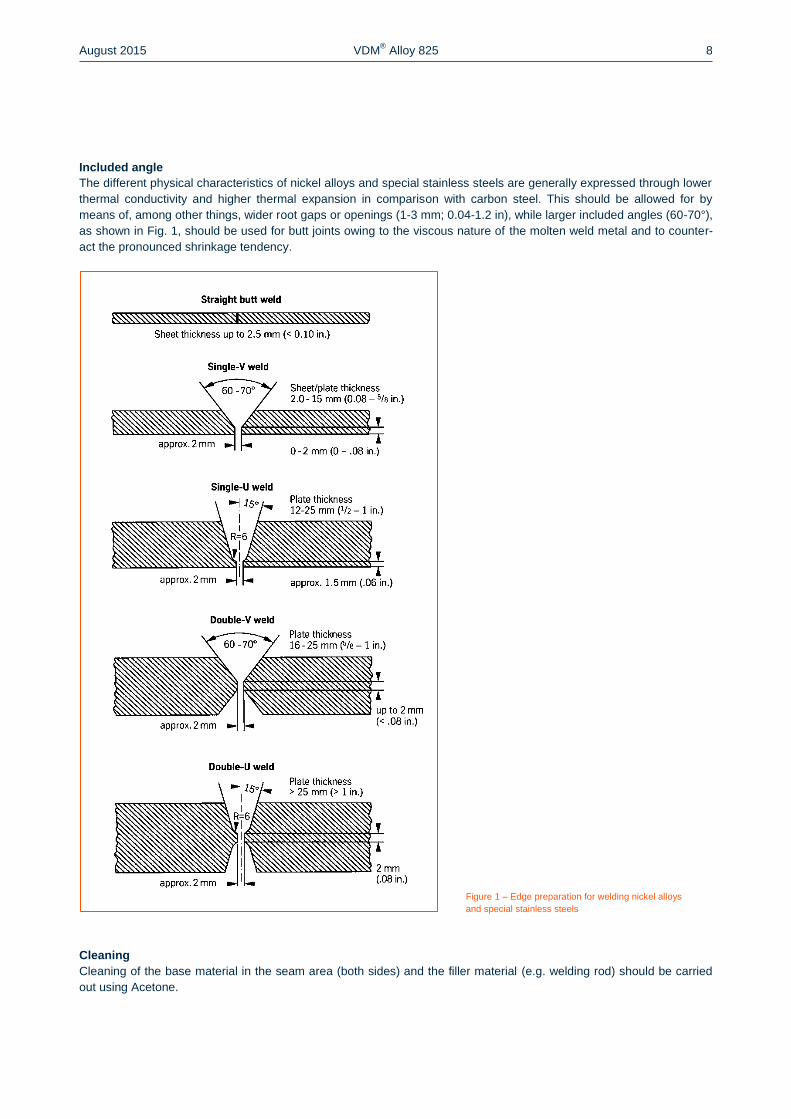
Included angle
The different physical characteristics of nickel alloys and special stainless steels are generally expressed through lower
thermal conductivity and higher thermal expansion in comparison with carbon steel. This should be allowed for by
means of, among other things, wider root gaps or openings (1-3 mm; 0.04-1.2 in), while larger included angles (60-70°),
as shown in Fig. 1, should be used for butt joints owing to the viscous nature of the molten weld metal and to counter-
act the pronounced shrinkage tendency.
Figure 1 – Edge preparation for welding nickel alloys
and special stainless steels
Cleaning
Cleaning of the base material in the seam area (both sides) and the filler material (e.g. welding rod) should be carried
out using Acetone.
August 2015 VDM® Alloy 825 9
Welding process
VDM® Alloy 825 can be joined to itself and to many other metals by conventional welding processes. These include
GTAW (TIG), plasma arc, GMAW (MIG/MAG) and SMAW (MMA). Pulsed arc welding is the preferred technique. For
the MAG process the use of a multi-component shielding gas (Ar + He + H2 + CO2) is recommended. For welding,
VDM® Alloy 825 should be in the annealed temper and be free from scale, grease and markings.
When welding roots, sufficient protection of the root needs to be ensured with pure argon (Ar 4.6) so that the welding
seam is free of oxides after welding. Root backing is also recommended for the first intermediate pass following the
initial root pass and in some cases even for the second pass, depending on the weld set-up.
Any discoloration/heat tint should be removed preferably by brushing with a stainless steel wire brush while the weld
metal is still hot.
Filler metal
The following filler material is recommended:
TIG/MIG and bare electrodes
VDM® FM 625 (W.-Nr. 2.4831)
DIN EN ISO 18274: S Ni 6602 (SG-NiCr 21 Mo 9 Nb)
AWS A 5.14: ERNiCrMo-3
Covered electrodes can be used.
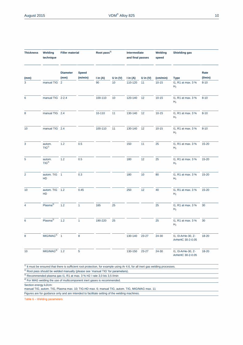
Welding parameters and influences
Care should be taken that the work is performed with a deliberately chosen, low heat input as indicated in Table 6 by
way of example. The stringer bead technique is recommended. The interpass temperature should not exceed 150 °C
(302 °F). The welding parameters should be monitored as a matter of principle.
The heat input Q can be calculated as follows:
= 0
1 000 (
cm)
U = arc voltage, volts
I = welding current, amps
v = welding speed, cm/min.
Post-weld treatment
Brushing with a stainless steel wire brush immediately after welding, i.e. while the metal is still hot generally results in
removal of heat tint and produces the desired surface condition without additional pickling. Pickling, if required or pre-
scribed, however, would generally be the last operation performed on the weldment. Please also refer to the infor-
mation on ‘Descaling and pic ling’. Neither pre- nor postweld heat treatments are required. Preheating before welding
is generally not necessary. Stabilizing annealing should be carried out on semi-finished products which were in use at
temperatures between 600 and 650 °C (1,112 and 1,202 °F) before they are reused in this critical temperature range
after repair welding.
August 2015 VDM® Alloy 825 10
Thickness Welding
technique
Filler material Root pass1)
Intermediate
and final passes
Welding
speed
Shielding gas
(mm)
Diameter
(mm)
Speed
(m/min) I in (A) U in (V) I in (A) U in (V) (cm/min) Type
Rate
(l/min)
3 manual TIG 2 90 10 110-120 11 10-15 I1, R1 at max. 3 %
H2
8-10
6 manual TIG 2-2.4 100-110 10 120-140 12 10-15 I1, R1 at max. 3 %
H2
8-10
8 manual TIG 2.4 10-110 11 130-140 12 10-15 I1, R1 at max. 3 %
H2
8-10
10 manual TIG 2.4 100-110 11 130-140 12 10-15 I1, R1 at max. 3 %
H2
8-10
3 autom.
TIG2)
1.2 0.5 150 11 25 I1, R1 at max. 3 %
H2
15-20
5 autom.
TIG2)
1.2 0.5 180 12 25 I1, R1 at max. 3 %
H2
15-20
2 autom. TIG
HD
1 0.3 180 10 80 I1, R1 at max. 3 %
H2
15-20
10 autom. TIG
HD
1.2 0.45 250 12 40 I1, R1 at max. 3 %
H2
15-20
4 Plasma3)
1.2 1 165 25 25 I1, R1 at max. 3 %
H2
30
6 Plasma3)
1.2 1 190-220 25 25 I1, R1 at max. 3 %
H2
30
8 MIG/MAG4)
1 8 130-140 23-27 24-30 I1, I3-ArHe-30, Z-
ArHeHC 30-2-0.05
18-20
10 MIG/MAG4)
1.2 5 130-150 23-27 24-30 I1, I3-ArHe-30, Z-
ArHeHC 30-2-0.05
18-20
1) It must be ensured that there is sufficient root protection, for example using Ar 4.6, for all inert gas welding processes.
2) Root pass should be welded manually (please see ‘manual TIG‘ for parameters).
3) Recommended plasma gas I1, R1 at max. 3 % H2 / rate 3,0 bis 3,5 l/min
4) For MAG welding the use of multicomponent inert gases is recommended.
Section energy kJ/cm:
manual TIG, autom. TIG, Plasma max. 10; TIG-HD max. 6; manual TIG, autom. TIG, MIG/MAG max. 11
Figures are for guidance only and are intended to facilitate setting of the welding machines.
Table 6 – Welding parameters
August 2015 VDM® Alloy 825 11
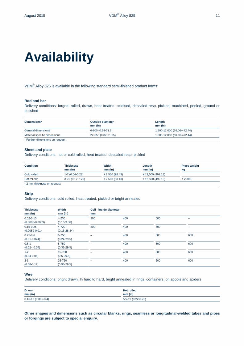
Availability
VDM® Alloy 825 is available in the following standard semi-finished product forms:
Rod and bar
Delivery conditions: forged, rolled, drawn, heat treated, oxidised, descaled resp. pickled, machined, peeled, ground or
polished
Dimensions* Outside diameter
mm (in)
Length
mm (in)
General dimensions 6-800 (0.24-31.5) 1,500-12,000 (59.06-472.44)
Material specific dimensions 22-550 (0.87-21.65) 1,500-12,000 (59.06-472.44)
* Further dimensions on request
Sheet and plate
Delivery conditions: hot or cold rolled, heat treated, descaled resp. pickled
Condition Thickness
mm (in)
Width
mm (in)
Length
mm (in)
Piece weight
kg
Cold rolled 1-7 (0.04-0.28) ≤ 2,500 (98.43) ≤ 12,500 (492.13)
Hot rolled* 3-70 (0.12-2.76) ≤ 2,500 (98.43) ≤ 12,500 (492.13) ≤ 2,300
* 2 mm thickness on request
Strip
Delivery conditions: cold rolled, heat treated, pickled or bright annealed
Thickness
mm (in)
Width
mm (in)
Coil - inside diameter
mm
0.02-0.15
(0.0008-0.0059)
4-230
(0.16-9.06)
300 400 500 –
0.15-0.25
(0.0059-0.01)
4-720
(0.16-28.34)
300 400 500 –
0.25-0.6
(0.01-0.024)
6-750
(0.24-29.5)
– 400 500 600
0.6-1
(0.024-0.04)
8-750
(0.32-29.5)
– 400 500 600
1-2
(0.04-0.08)
15-750
(0.6-29.5)
– 400 500 600
2-3
(0.08-0.12)
25-750
(0.98-29.5)
– 400 500 600
Wire
Delivery conditions: bright drawn, ¼ hard to hard, bright annealed in rings, containers, on spools and spiders
Drawn
mm (in)
Hot rolled
mm (in)
0.16-10 (0.006-0.4) 5.5-19 (0.22-0.75)
Other shapes and dimensions such as circular blanks, rings, seamless or longitudinal-welded tubes and pipes
or forgings are subject to special enquiry.
August 2015 VDM® Alloy 825 12
Date of publication
15 August 2015
Publisher
VDM Metals GmbH
Plettenberger Straße 2
58791 Werdohl
Germany
Disclaimer
All information contained in this data sheet are based on the results of research and development work carried out by
VDM Metals GmbH, and the data contained in the specifications and standards listed available at the time of printing.
The information does not represent a guarantee of specific properties. VDM Metals reserves the right to change infor-
mation without notice. All information contained in this data sheet is compiled to the best of our knowledge and is pro-
vided without liability. Deliveries and services are subject exclusively to the relevant contractual conditions and the
General Terms and Conditions issued by VDM Metals GmbH. Use of the most up-to-date version of this data sheet is
the responsibility of the customer.
Imprint
VDM Metals GmbH
Plettenberger Straße 2
58791 Werdohl
Germany
Tel +49 (0)2392 55 0
Fax +49 (0)2392 55 22 17
www.vdm-metals.com