Embed Size (px)
Citation preview

BIS V-6102 PROFIBUSTechnical Description, User’s Guide
48,2
36,
4
31
168
,3 +
6,0
2,5
42,7 61,9
157
,6 +
6,0
5,3
4
english

www.balluff.com
www.balluff.com
BIS V-6102 PROFIBUSProcessor unit
3
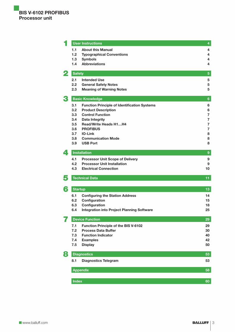
1 User Instructions 4
1.1 About this Manual 41.2 Typographical Conventions 41.3 Symbols 41.4 Abbreviations 4
2 Safety 5
2.1 Intended Use 52.2 General Safety Notes 52.3 Meaning of Warning Notes 5
3 Basic Knowledge 6
3.1 Function Principle of Identification Systems 63.2 Product Description 63.3 Control Function 73.4 Data Integrity 73.5 Read/Write Heads H1…H4 73.6 PROFIBUS 73.7 IO-Link 83.8 Communication Mode 83.9 USB Port 8
4 Installation 9
4.1 Processor Unit Scope of Delivery 94.2 Processor Unit Installation 94.3 Electrical Connection 10
5 Technical Data 11
6 Startup 13
6.1 Configuring the Station Address 146.2 Configuration 156.3 Configuration 186.4 Integration into Project Planning Software 25
7 Device Function 29
7.1 Function Principle of the BIS V-6102 297.2 Process Data Buffer 307.3 Function Indicator 407.4 Examples 427.5 Display 50
8 Diagnostics 53
8.1 Diagnostics Telegram 53
Appendix 58
Index 60

BIS V-6102 PROFIBUSProcessor unit
4
This manual describes the processor unit for BIS V-6102 Identification Systems and startup instructions for immediate operation.
The following conventions are used in this manual:
Enumerations are shown as a list with an en-dash.– Entry 1.– Entry 2.
Action instructions are indicated by a preceding triangle. The result of an action is indicated by an arrow.
► Action instruction 1. ⇒ Action result.
► Action instruction 2.
Numbers:– Decimal numbers are shown without additional indicators (e.g. 123).– Hexadecimal numbers are shown with the additional indicator hex (e.g. 00hex).
Parameters:Parameters are shown in italics (e.g. CRC_16).
Directory paths:References to paths where data is stored or to be saved are shown in small caps (e.g. Project:\Data tyPes\User-DefineD).
Control characters:Control characters for sending are set in angle brackets (e.g. <ACK>).
ASCII code:Characters transmitted in ASCII code are set in apostrophes (e.g. ‘L’).
Important!This symbol indicates a safety instruction that must be followed without exception.
Note, tipThis symbol indicates general notes.
BIS Balluff Identification SystemCP Code presentCRC Cyclic Redundancy CheckDID Device IDDP Decentralized peripheralsI/O port Digital input and output portEEPROM Electrical Erasable and Programmable ROMEMC Electromagnetic CompatibilityFCC Federal Communications CommissionFE Function groundLF CR Line Feed with Carriage ReturnMAC Media Access Controln. c. not connectedPC Personal ComputerPROFIBUS Process Field BusPLC Programmable Logic ControllerTag Data carrierUID Unique IdentifierVID Vendor ID
1.1 About this Manual
1.2 Typographical Conventions
Enumerations
Actions
Syntax
1.3 Symbols
1.4 Abbreviations
1 User Instructions

www.balluff.com
BIS V-6102 PROFIBUSProcessor unit
5
The processor unit BIS V-6102 is a component of the BIS V identification system. Within the identification system it is used for linking to a host computer (PLC, PC). It may be used only for this purpose in an industrial environment corresponding to Class A of the EMC Law.This description applies for processor units of the following series:– BIS V-6102-019-C001– BIS V-6102-019-C101
Installation and startupInstallation and startup are to be performed by trained technical personnel only. Any damage resulting from unauthorized manipulation or improper use voids the manufacturer’s guarantee and liability claims against the manufacturer.When connecting the processor unit to an external controller, observe proper selection and polarity of the connection as well as the power supply (see “Assembly” on page 9).The processor unit may only be used with an approved power supply (see “Technical Data” on page 11).
Conformity
This product was developed and manufactured in accordance with all applicable European Directives.developed and manufactured. CE conformity has been verified.
All approvals and certifications are no longer valid if:– Components are used that are not part of the BIS V Identification System,– Components are used that have not been explicitly approved by Balluff.
Operation and testingThe operator is responsible for ensuring that local safety regulations are observed.In the event of defects and non-correctable faults in the identification system, take the system out of service and secure it from unauthorized use.
Important!The pictogram used with the word “Caution” warns of a situation that could harm someone’s health or damage equipment. Failure to observe these warning notes may result in injury or damage to equipment.
► Always observe the described measures for preventing this danger.
2.1 Intended Use
2.2 General Safety Notes
2.3 Meaning of Warning Notes
2 Safety

BIS V-6102 PROFIBUSProcessor unit
6
The BIS V Identification System is classified as a non-contacting system with read and write function, which not only allows it to convey information programmed permanently in the data carrier, but also to collect and pass on current information.
The main components of the BIS V Identification System are:– Processor unit,– Read/write heads,– data carrier.
Figure 1: System overview
3 4
2
1 1
56
H1H2H3H4
IO-Link
123
BIS VPROFIBUS DPData carrier (max. 1 per R/W head)
456
Read/write heads H1…H4 Service/IO-LinkFunction ground
The main areas of application are:– In production for controlling material flow (e.g. for model-specific processes, conveying
systems that transport workpieces, acquisition of safety-related data)– In warehousing for monitoring material movement– Transporting and conveying
Processor Unit BIS V-6102:– Metal housing– Round connector terminations– Four read/write heads can be connected– 1 × IO-Link module or standard I/O port can be connected– Power for the system components provided by the processor unit– Power for the data carrier provided by the read/write heads via carrier signal– USB port– PROFIBUS DP input and output– Display with keys for startup and configuration– Control displays
3.1 Function Principle of Identification Systems
3.2 Product Description
3 Basic Knowledge

www.balluff.com
BIS V-6102 PROFIBUSProcessor unit
7
The processor unit is the link between data carrier and host system. It manages two-way data transfer between data carrier and R/W head and provides buffer storage. The processor unit uses the read/write head to write data from the host system to the data carrier or reads the data from the carrier and makes it available to the host system.
Host systems may be the following:– A control computer (e.g. industrial PC)– A PLC
Double bit string:In order to ensure complete transmission of all data in the data buffer, the control bits in the data buffer’s first and last byte (bit string) are transmitted and compared for each R/W head. If both bit strings are the same, then the data is updated completely and can be taken over. This means that the data for each R/W head is only valid if both bit strings are the same. Thus, the host system also has to compare the bits in the bit strings.
In order to increase data integrity, data transfer between the data carrier and processor unit and the storage device must be monitored using a check procedure.A CRC_16 data check can be enabled for this via parameter configuration.With the CRC_16 data check, a check code that allows the validity to be checked at any time is written to the data carrier.
A CRC_16 data check provides the following advantages:– Data integrity even during the non-active phase (data carrier outside the R/W head).– Shorter read time – page is read once.
For BIS V-6102-019-C001, read/write heads of the BIS VM-3… and BIS VL-3… series can be connected to terminals H1…H4.BIS V-6102-019-C101 also supports read/write heads of the BIS C-3… series (adapter required).Connecting the read/write heads only using shielded cables is recommended for compliance with the EMC Directives.
Open bus system for process and field communication in cell networks with few nodes and for data communication in accordance with IEC 61158/EN 50170. Automation devices, such as PLCs, PCs, operating and observation devices, sensors or actuators, can communicate using this bus system. PROFIBUS DP is used in the BIS V-6102.
3.3 Control Function
3.4 Data Integrity
3.5 Read/Write Heads H1…H4
3.6 PROFIBUS
3 Basic Knowledge

BIS V-6102 PROFIBUSProcessor unit
8
IO-Link is defined as a standardized point-to-point connection between sensors/actuators and an I/O module. An IO-Link sensor/actuator can send additional communication data (e.g. dia-gnostics signals) in addition to the binary process signals over the IO-Link interface.
Compatibility with standard I/O:– IO-Link sensors/actuators can be connected to existing I/O modules.– Sensors/actuators which are not IO-Link capable can be connected to an IO-Link module.– Standard sensor/actuator cables can be used.
Key technical data:– Serial point-to-point connection– Communication as add-on to standard I/O– Standard I/O connection technology, unshielded, 20 m cable length– Communication using 24 V pulse modulation, standard UART protocol
Process data (cyclical):The GSD file provides different data modules for representing the sensor map:– Inputs: 1 byte – 32 bytes– Outputs: 1 byte – 32 bytes– Or combined input/output modules
Deterministic time behavior:– Typically 2 ms cycle time for 16 bits of process data and 38.4 kbaud transmission rate.
Service data (diagnostics, parameters):– Parallel and non-reactive to process data
– Startup parameter setting possible using communication, then– binary switching signal
The device can be connected to a computer’s USB port using the “Service/IO-Link” jack and then behaves like a USB stick. This allows access to the internal memory, where the manual, the GSD file and a communications driver for service functions are saved. In addition, the BIS V has to be connected to a voltage source. The communication driver can be installed as needed, but is not required for the USB port and BIS V to function.
NoteVisit www.balluff.com for more information on available software and accessories.
3.7 IO-Link
3.8 Communication Mode
Standard I/O mode
3.9 USB Port
3 Basic Knowledge

www.balluff.com
BIS V-6102 PROFIBUSProcessor unit
9
Included in the scope of delivery:– BIS V-6102– 5 × closure cap– Safety Notes
NoteVisit www.balluff.com for more information on available software and accessories.
Figure 1: Mechanical connection
48,2
36,
4
31
168
,3 +
6,0
2,5
42,7 61,9
157
,6 +
6,0
5,3
4
(dimensions in mm)
Figure 2: Installation examples (A: attachment to DIN rails, B: attachment to T-slotted framing)
1
2 3BA
4
12
DIN railFastening
34
T-slotted framingHolder for screw mounting
► Select a suitable installation position. ► Secure the processor unit using two M5 screws (strength category 8.8, lightly oiled, tighte-
ning torque M = 5.5 Nm).
4.1 Processor Unit Scope of Delivery
4.2 Processor Unit Installation
4 Assembly

BIS V-6102 PROFIBUSProcessor unit
10
NoteMake the ground connection either directly or using an RC combination to ground.
Connections
H 1
Bus In
Power
Bus Out
H 2
H 4H 3
Service / IO-Link
FE
H1…H4 Read/write heads
Service/IO-Link USB functionService/IO-Link(master function)
Bus in PROFIBUS DP input
Bus out PROFIBUS DP output
FE Function ground
Figure 3: Electrical connection
H1…H45-pin M12 female, A-coded
Power5-pin 7/8" male
2
5
1
5
34
2
3 41
A0VB
H1...H4
VP
N.C.
PIN Function
1 +24 V DC
2 A
3 0 V
4 B
5 n. c.
34
2
3
1
4
5
5
21
VP(Aktor)VP(Sensor) BUSFE0V0V
POWERPIN Function
1 0 V
2 0 V
3 FE
4 +24 V DC
5 n. c.
IO-Link / Service5-pin M12 female, A-coded
2
5
1
5
34
2
34 1
USB Tx0VQ/C (IO/Link)
IO-Link-Master
VP
USB Rx
IO-Link
PIN Function
1 VP (+24 V DC)
2 n. c.
3 0 V
4 Q/C (IO-Link) or digital input,
optional: output
5 n. c.
Service
PIN Function
1 n. c.
2 USB+
3 0 V
4 n. c.
5 USB−
Bus out5-pin M12 female, B-coded
Bus in5-pin M12 male, B-coded
5 N.C.5
DGNDAVP
B
BUS Out
23
14
1
4
3
2
PIN Function
1 VP
2 A
3 DGND
4 B
5 n. c.
5 N.C.
DGNDAVP
B
23
1
4
5
Bus In3
2
4
1
PIN Function
1 VP
2 A
3 DGND
4 B
5 n. c.
4.3 Electrical Connection
4 Installation

www.balluff.com
BIS V-6102 PROFIBUSProcessor unit
11
48,2
6,2
36,
4
31
168
,3 +
6,0
61,9
17,
3
68,
1
93,
1 1
49
41,
8
5,3
30 5,7
42,7
157
,6 +
6,0
Figure 1: Dimensions in mm
Housing material Zinc die-cast housing
H1…H4 VS 24 V DC - 5-pin M12 female, A-coded
Service/IO-Link (master function) 5-pin M12 female, A-coded
Power 5-pin 7/8" male
Bus out 5-pin M12 female, B-coded
Bus in 5-pin M12 male, B-coded
Degree of protection IP65 (with connectors)
Weight 800 g
Supply voltage VS 24 V DC ±20% LPS Class 2
Residual ripple ≤ 10%
Current consumption ≤ 2 A
Application interfaces PROFIBUS DP, IO-Link
IO-Link port M12, A-coded, female
Pin 1 +24 V DC, 1 A
Pin 2 USB+
Pin 3 0 V
Pin 4 IO-Link / input / output max. 500 mA
Pin 5 USB–
Dimensions
Mechanical data
Electrical data
Application interfaces
5 Technical Data

BIS V-6102 PROFIBUSProcessor unit
12
Ambient temperature 0 °C…+60 °C
Storage temperature 0 °C…+60 °C
EMC (BIS V-6102-019-C001)
– IEC EN 61000-6-2
– IEC EN 61000-4-2/4/5/6 – Severity level 2B/3B/2B/3A
– IEC EN 61000-4-3
80 MHz – 1000 MHz – Severity level 3A
1400 MHz – 2000 MHz – Severity level 3A
2000 MHz – 2700 MHz – Severity level 2A
– Emission as per EN 55016-2-3 – EN61000-6-4
EMC (BIS V-6102-019-C101)
– EN 300330-2
– EN 61000-4-2/4/6 – Severity level 2B/2B/2A
– EN 61000-4-3
80 MHz – 1000 MHz – Severity level 3A
1400 MHz – 2000 MHz – Severity level 3A
2000 MHz – 2700 MHz – Severity level 2A
– Emission as per EN 301489-1/-3 – EN 55022 (class A)
Vibration/shock EN 60068 Part 2-6/27/29
Operating conditions
5 Technical Data

www.balluff.com
BIS V-6102 PROFIBUSProcessor unit
13
The processor unit BIS V-6102 and the host system communicate via PROFIBUS DP.The PROFIBUS DP system consists of the following components:– Bus master– Bus modules/slaves (here, the processor unit BIS V-6102)
Important note for implementation using PLCsThere are controllers where the PROFIBUS DP data range is not transmitted synchro-nously with the update of the input/output map. If more than 2 bytes of data are transmitted, a mechanism must be used that guarantees that the data in the PLC and the data in the BIS V are always the same!
1st option: Synchronous data transmission as a setting on the masterIn this method, the bus master ensures that all of the data necessary for the respec-tive slave is transmitted together. Usually a special software function must be used in the PLC that also controls the access between the PLC and bus master so that all data is always transmitted together.
2nd option: Configuring a 2nd bit string (always active)The data exchange between PLCs and BIS is controlled via what is known as a bit string. This is always the first byte of the respective R/W head in the data buffer. This bit string is present in both the input range (data from BIS to the PLC) and the output range (data from the PLC to the BIS). If this bit string is now transmitted as the last byte as well, the consistency of the transmitted data can be guaranteed by compa-ring these two bytes.This method affects neither the PLC cycle time nor the bus access time. Only one byte in the data buffer is required for the byte of the 2nd bit string instead of using it for data.
In order to configure the parameters for the bus master correctly based on type, the device master data for the BIS V-6102 evaluation data are included in the form of a GSD file. The data can be found in the processor unit’s internal memory and can be retrieved from there via the USB port.
Each processor unit BIS V-6102 is shipped with a station address of 126. Beforebeing used on the bus, this has to be configured individually first (see page 14).
The data exchange takes place with the host system in the input and output buffer.The size of these buffers must be configured by the master.
NoteThe possible buffer sizes for each read/write head are stored in the GSD file. A mini-mum size of 4 and a maximum size of 128 bytes can be configured; the value must always be an even number. The maximum total buffer size of 244 bytes must not be exceeded.
There are up to 47 bytes (user parameter bytes) in the processor unit BIS V-6102 that have to be transmitted during parameter configuration. The significance of the 47 bytes for parameter configuration is described on page 18.
NoteThe preset is stored in the GSD file.
PROFIBUS DP
Device master data
Station address
Input / output buffer
Userparameter bytesUser parameter bytes
6 Commissioning

BIS V-6102 PROFIBUSProcessor unit
14
The station address used to trigger the device on the bus can be assigned using the display. Each address may be used only once.
– Permitted working range: 0 to 125– Each PROFIBUS node has to be assigned a unique address.– The address is read once after power is turned on.– If the address is changed, this change becomes effective after a power reset on the module.
A DP master is generally assigned addresses 0 to 2. We recommend setting addresses using values of 3 and higher.
Details for configuring the station address and for menu navigation on the display are described in the chapter “Display” on page 50.
6.1 Configuring the Station Address
Addressing
Display setting/menu navigation
6 Startup

www.balluff.com
BIS V-6102 PROFIBUSProcessor unit
15
In project planning for PROFIBUS devices, a device is mapped as a modular system that con-sists of a “BIS V-6102” header module and multiple data modules.
The device data required for project planning is stored in GSD files (General Station Description). The data modules of each read/write head, each IO-Link port and possible additional modules are represented in the project planning software relative to their slot. The GSD file makes the possible data modules (inputs/outputs for the read/write heads and the IO-Link port for various data widths) available. Appropriate data modules are assigned to a specific slot for configuring the BIS V-6102.
A module always has to be plugged in at slots 1 to 6 (see table, at bottom). If optional additional modules are plugged in for the IO-Link port, these have to be plugged in from slot 7 onward without a slot left empty in between.
The “BIS V-6102” header module always has to be plugged in at slot 1.The data modules for the 4 read/write heads can be plugged in at slots 2 to 5. If a head is not going to be used, a “R/W head not used” module must be plugged in at that slot.Depending on use, an IO-Link port, a standard I/O, an IO-Link data module or an SIO module can be plugged in at slot 6. If the IO-Link port is not going to be used, slot 6 has to be equipped with a “not used” module.
Slot Module Function
1 BIS V-6102 header module
Parameter configuration, no process data
2 Read/write head Parameter configuration and process data
3 Read/write head
4 Read/write head
5 Read/write head
6 IO-Link port pin 4 IO-Link data modules of various data width or configu-rable as a standard I/O port
7 Slots for optional additional modules
– Input pin 4– Output pin 4– Communication status– IO-Link diagnostics enable– Station diagnostics– Peripheral error– Sensor short circuit
8
9
10
11
12
13
6.2 Configuration
GSD file
6 Startup

BIS V-6102 PROFIBUSProcessor unit
16
Data modules for standard I/O ports:
Data module Data width
Standard I/O See “Additional modules” on page 17
Data modules for IO-Link_inputs
Data module Data width
IOL_I_1byte 1 byte
IOL_I_2byte 2 bytes
IOL_I_4byte 4 bytes
IOL_I_6byte 6 bytes
IOL_I_8byte 8 bytes
IOL_I_10byte 10 bytes
IOL_I_16byte 16 bytes
IOL_I_24byte 24 bytes
IOL_I_32byte 32 bytes
Data modules for IO-Link_outputs
Data module Data width
IOL_O_1byte 1 byte
IOL_O_2byte 2 bytes
IOL_O_4byte 4 bytes
IOL_O_6byte 6 bytes
IOL_O_8byte 8 bytes
IOL_O_10byte 10 bytes
IOL_O_16byte 16 bytes
IOL_O_24byte 24 bytes
IOL_O_32byte 32 bytes
Coding IO-Link data modules
6 Startup

www.balluff.com
BIS V-6102 PROFIBUSProcessor unit
17
Data modules for IO-Link_inputs_outputs
Data moduleData width
Input Output
IOL_I/O_1/_1byte 1 byte 1 byte
IOL_I/O_2/_2byte 2 bytes 2 bytes
IOL_I/O_2/_4byte 2 bytes 4 bytes
IOL_I/O_4/_4byte 4 bytes 4 bytes
IOL_I/O_4/_2byte 4 bytes 2 bytes
IOL_I/O_2/_8byte 2 bytes 8 bytes
IOL_I/O_4/_8byte 4 bytes 8 bytes
IOL_I/O_8/_2byte 8 bytes 2 bytes
IOL_I/O_8/_4byte 8 bytes 4 bytes
IOL_I/O_8/_8byte 8 bytes 8 bytes
IOL_I/O_10/_10byte 10 bytes 10 bytes
IOL_I/O_4/_32byte 4 bytes 32 bytes
IOL_I/O_32/_4byte 32 bytes 4 bytes
IOL_I/O_16/_16byte 16 bytes 16 bytes
IOL_I/O_24/_24byte 24 bytes 24 bytes
IOL_I/O_32/_32byte 32 bytes 32 bytes
Note!Project planning software of various providers mostly offers graphical assistance during configuration; the configuration string is automatically created.
Additional modules
Additional moduleData width
Input Output
Communication status 1 byte
IO-Link diagnostics enable 1 byte
Station diagnostics 1 byte
Peripheral error 1 byte
Sensor short circuit 1 byte
Input pin 4 1 byte
Output pin 4 1 byte
6 Startup

BIS V-6102 PROFIBUSProcessor unit
18
Byte Bit Meaning
1–3 Reserved for DPV1
4 0 Global diagnostic
1 Channel-related diagnostic
2 Low voltage bus / sensor supply
3 Low voltage actuator supply
4–7 Reserved
5 0–2 IO-Link port function
3–7 Reserved
6 0–1 IO-Link port safe state
2–7 Reserved
7 0 Keyboard/LCD: read only
1 Device LEDs off
2–7 Reserved
8 Reserved
9Parameter for R/W head 1
0 CRC
1 Dynamic mode
2 Type serial number
3 “Slow tag detection” energy saving function
4 “Low antenna power” energy saving function
5 “Head LEDs off” energy saving function
6–7 Reserved
10Tag type (parameter for R/W head 1)
0–7 0: All data carriers are detected
10: Mifare
11: ISO 15693
20: EM4x02
21: Hitag1
22: HitagS
30: BIS C 32 Byte
31: BIS C 64 Byte
11 (parameter for R/W head 1)
0–3 UID compare count
4–7 Reserved
12–14 Parameters for R/W head 2; structured like bytes 9–11
15–17 Parameters for R/W head 3; structured like bytes 9–11
18–20 Parameters for R/W head 4; structured like bytes 9–11
21–47 Parameters for IO-Link module
6.3 Configuration
User parameter bytes
6 Startup

www.balluff.com
BIS V-6102 PROFIBUSProcessor unit
19
This function can be used to permit / suppress all of the module’s diagnostics messages. (optical diagnostics signals are not affected)
This function permits / suppresses channel-related diagnostics messages.
This function can be used to permit / suppress the diagnostics message Sensor supply under-voltage. (optical diagnostics signals are not affected)
This function can be used to permit / suppress the diagnostics message Actuator supply under-voltage. (optical diagnostics signals are not affected)
Here, the function of the IO-Link port can be defined:
NO = Input as normally open contact
NC = Input as normally closed contact
Output = Output function
IO-Link = IO-Link function
Normally open after configura-tion
= SIO mode; an IO-Link device can be configured via IO-Link and afterward switched over to an SIO mode in which the IO-Link port pin functions as a simple switch input
Normally closed after configu-ration
= SIO mode, as with normally open after configuration, but as normally closed input
This function is an extension of the IO-Link port starting configuration. A safe state that the port is to take on in the case of a loss of bus communication can be predefined for the port.
If this function is enabled, then the PROFIBUS address can no longer be changed via the dis-play.
If this function is enabled, then the read/write head LEDs on the BIS V-6102 processor unit are shut off after 30 min. The parameters for this function are configured in the header module.
Description of individual parameters
Global diagnostic
Channel related diagnostic
Low voltage bus / sensor supply
Low voltage actuator supply
IO-Link port function
IO-Link port safe state
Keyboard/LCD: read only
Device LEDs off
6 Startup

BIS V-6102 PROFIBUSProcessor unit
20
The CRC check is a procedure for determining a check value for data in order to be able to recognize transmission errors. If the CRC check is activated, an error message is sent when a CRC error is detected.
ChecksumM and L system:The checksum is written to the data carrier as 2 bytes of information. 2 bytes per block are lost. This leaves 14 bytes per block available. The usable number of bytes can be found in the follow-ing table.
C system:The checksum is written to the data carrier as 2 bytes of information per page. 2 bytes per page are lost, i.e. the page size is 30 bytes or 62 bytes depending on the data carrier type.
The number of usable bytes thus decreases when using the checksum.
Balluff data carrier type Memory capacity Usable bytes for CRC_16
BIS M-1_ _-01 752 bytes 658 bytes
BIS M-1_ _-02 2000 bytes 1750 bytes
BIS M-1_ _-03 112 bytes 98 bytes
BIS M-1_ _-04 256 bytes 224 bytes
BIS M-1_ _-05 224 bytes 196 bytes
BIS M-1_ _-06 288 bytes 252 bytes
BIS M-1_ _-07 992 bytes 868 bytes
BIS M-1_ _-08 160 bytes 140 bytes
BIS M-1_ _-09 32 bytes 28 bytes
BIS M-1_ _-10 736 bytes 644 bytes
BIS M-1_ _-11 8192 bytes 7168 bytes
BIS M-1_ _-13 32786 bytes 28672 bytes
BIS M-1_ _-14 65536 bytes 57344 bytes
BIS M-1_ _-15 131072 bytes 114688 bytes
BIS M-1_ _-20 8192 bytes 7168 bytes
BIS L-1_ _-01 192 bytes 168 bytes
BIS L-2_ _-03 5 bytes (read-only) —
BIS L-1_ _-05 192 bytes 168 bytes
BIS C-1_ _-04 511 bytes 450 bytes
BIS C-1_ _-05 1023 bytes 930 bytes
BIS C-1_ _-11 2047 bytes 1922 bytes
BIS C-1_ _-32 8192 bytes 7936 bytes
CRC check
6 Startup

www.balluff.com
BIS V-6102 PROFIBUSProcessor unit
21
As soon as the Dynamic mode function is enabled, the processor unit accepts the read/write job from the host system and stores it, regardless of whether a data carrier is in the active zone of the R/W head or not. If a data carrier enters the active range of the R/W head, the stored job is run.
NoteTo achieve the read times specified on page 38 in dynamic operation, the Tag Type parameter has to be set to “BIS C 32 Byte” or “BIS C 64 Byte” on the respective head.
If this function is enabled, the type of the read/write head as well as the data carrier type and serial number (UID = Unique Identifier) for the data carrier are output when CP occurs.The length of the serial number can vary depending on the type of data carrier. To be able to determine the length, the data is preceded by a length field.
NoteBIS C data carriers do not have a UID value.
Data for-mat
1 byte 1 byte 1 byte 4 bytes or 8 bytes
Meaning Length (number of bytes including length)
Read/write head type
Data carrier type UID (Mifare or Hitag 1) or UID (ISO 15693)
BIS VM-3_ _-001-S4 BIS VL-3_ _-001-S4 BIS C-3…
03 02 01
For this option, the antenna on the read/write head is switched on for data carrier detection only every 200 ms. The parameters for this function are configured in the respective read/write head module.
Transmitting power is reduced when using this parameter. The parameters for this function are configured in the respective read/write head module and is reserved for future read/write heads.
This parameter switches off the LEDs on the respective read/write head. The parameters for this function are configured in the respective read/write head module.
Dynamic mode
Type serial number
Slow tag detection
Low antenna power
Head LEDs off
6 Startup

BIS V-6102 PROFIBUSProcessor unit
22
The following data carriers are available for the processor unit BIS V-6102.
Mifare data carriers (for read/write heads BIS VM):
Balluff data carrier type
Manufacturer Description Memory capacity
Memory type
BIS M-1_ _-01 NXP Mifare Classic 752 bytes EEPROM
BIS M-1_ _-10 NXP Mifare Classic 736 bytes EEPROM ISO 15693 data carriers (for read/write heads BIS VM):
Balluff data carrier type
Manufacturer Description Memory capacity
Memory type
BIS M-1_ _-02 Fujitsu MB89R118 2000 bytes FRAM
BIS M-1_ _-03 NXP SL2ICS20 112 bytes EEPROM
BIS M-1_ _-04* Texas Instruments TAG-IT Plus 256 bytes EEPROM
BIS M-1_ _-05* Infineon SRF55V02P 224 bytes EEPROM
BIS M-1_ _-06* EM EM4135 288 bytes EEPROM
BIS M-1_ _-07 Infineon SRF55V10P 992 bytes EEPROM
BIS M-1_ _-08* NXP SL2ICS530 160 bytes EEPROM
BIS M-1_ _-09* NXP SL2ICS500 32 bytes EEPROM
BIS M-1_ _-11 Balluff BIS M-1 8192 bytes FRAM
BIS M-1_ _-13 Balluff BIS M-1 32768 bytes FRAM
BIS M-1_ _-14 Balluff BIS M-1 65536 bytes FRAM
BIS M-1_ _-15 Balluff BIS M-1 161072 bytes
FRAM
BIS M-1_ _-20 Fujitsu MB89R112 8192 bytes FRAM
* On request
For read/write heads BIS VL:
Balluff data carrier type
Manufacturer Description Memory capacity
Memory type
BIS L-1_ _-01 NXP Hitag1 192 bytes EEPROM
BIS L-2_ _-03 EM EM4x02 5 bytes (read-only) —
BIS L-1_ _-05 NXP HitagS 192 bytes EEPROM
For read/write heads BIS C (with adapter):
Balluff data carrier type
Manufacturer Memory capacity
Memory type
Memory organization
BIS C-1_ _-04 Balluff 511 bytes EEPROM 32-byte blocks
BIS C-1_ _-05 Balluff 1023 bytes EEPROM 32-byte blocks
BIS C-1_ _-11 Balluff 2047 bytes EEPROM 64-byte blocks
BIS C-1_ _-32 Balluff 8192 bytes FRAM 64-byte blocks
NoteThe data carriers contain additional memory ranges for configuration and protected data. These ranges cannot be processed using the BIS V-6102 processor unit.
Tag type
6 Startup

www.balluff.com
BIS V-6102 PROFIBUSProcessor unit
23
The configuration of the IO-Link port always consists of 27 bytes.
It is configured via project planning using the GSD file (IO-Link module, slot 6).
Bit No.
Byte7 6 5 4 3 2 1 0 Description
21 Module identifier 10hex
22 Basis Cycle time Cycle time with multiplier (cycle time formula multiplier)
23 Offset data window 0…31 bytes24 Length data window 0…16 bytes
25 Validation type
Validation type0 – No validation1 – Compatible (VID + DID)2 – Identical (VID + DID + SerNum)
26 IOL Vendor ID 1Vendor ID
27 IOL Vendor ID 228 IOL Device ID 1
Device ID29 IOL Device ID 230 IOL Device ID 331 IOL Serial number 1
Serial number optional… …46 IOL Serial number 1647 Parameter server Optional
IO-Link port
IO-Link port configuration (optional)
6 Startup

BIS V-6102 PROFIBUSProcessor unit
24
The cycle time controls the timing for triggering the IO-Link device. The factory default setting is 0 (Auto). It is recommended that this value be retained.The cycle time is stored in the IO-Link device (slave) and is detected automatically. Only times that are slower than the automatically selected times can be set manually.
The offset (offset data window) can be used by the start byte with length (length data window) to define the end byte of the process data. This setting is only for the input data, has no influence on the actual process data length and is for visual purposes only.
Whether a connected IO-Link device receives access to the IO-Link master can be controlled using validation.
Configuration options:– 0
No validation– 1 Compatible
Only allows communication to the IO-Link master for devices whose vendor ID (VID) and device ID (DID) correspond to the configured values.
– 2 Identical See “1 Compatible”; in addition, the serial number of the IO-Link device is checked
Vendor ID for the IO-Link device (refer to the manual for the device)
Device ID for the IO-Link device (refer to the manual for the device)
Serial number for the IO-Link device (if available; refer to the IO-Link device’s type plate)
Automatic upload (IO-Link slave → IO-Link master) or download (IO-Link master → IO-Link slave) can be switched on using this parameter.For automatic upload, the parameter configuration is read when an IO-Link device is plugged in. For automatic download, the parameter configuration is transmitted to the device when an IO-Link device is plugged in.
Background:The automatic upload makes it possible to read in the parameter configuration of a correctly configured device when plugging one in. If an IO-Link device has to be replaced, the previously read in parameter configuration from the old device is transferred to the new device when it is plugged in.
The “Upload” option can be disabled by having a valid parameter set read.Configuration options:– 8Xhex: Switch on– X1hex: Switch on upload– X2hex: Switch on download
Cycle time
Offset data window and Length data window
Validation type
IOL Vendor ID (VID)
IOL Device ID (DID)
IOL Serial number, optional
Parameter server, optional
6 Startup

www.balluff.com
BIS V-6102 PROFIBUSProcessor unit
25
The connection of a BIS V-6102 to a Siemens S7 controller using “SIMATIC Manager” is shown as an example. The exact procedure depends on the project planning software used.
To perform project planning on the PC, the GSD file for the module must be installed: ► Open a new project. ► Open the hardware configurator. ► Select the “Tools | Install new GSD” menu command.
⇒ An “Install new GSD file” dialog will appear. ► Select directory and GSD file.
⇒ The [Install] button only becomes active if a GSD file is selected. ► Click on [Install].
⇒ The GSD file is installed. ⇒ A message appears once the process has finished.
► Confirm the message and close the window. ► Select the menu command “Tools | Update catalog”.
⇒ The devices are displayed in the product tree.
Figure 1: Parameter configuration with a GSD file
6.4 Integration into Project Planning Software
Installing the GSD file
6 Startup

BIS V-6102 PROFIBUSProcessor unit
26
The devices are located in the hardware catalog under “Other field devices”, “Ident systems”, “Balluff”, “RFID”. The module is added as a DP slave.
► Select the PROFIBUS rail. ► Double-clicking adds the device as a DP slave.
⇒ The slots are assigned the default settings.
Figure 2: Adding the BIS V-6102 as a slave
► Determine the PROFIBUS address of the slave.
Figure 3: Determining the slave address
Adding a DP slave
Determining the slave address
6 Startup
www.balluff.com
BIS V-6102 PROFIBUSProcessor unit
27
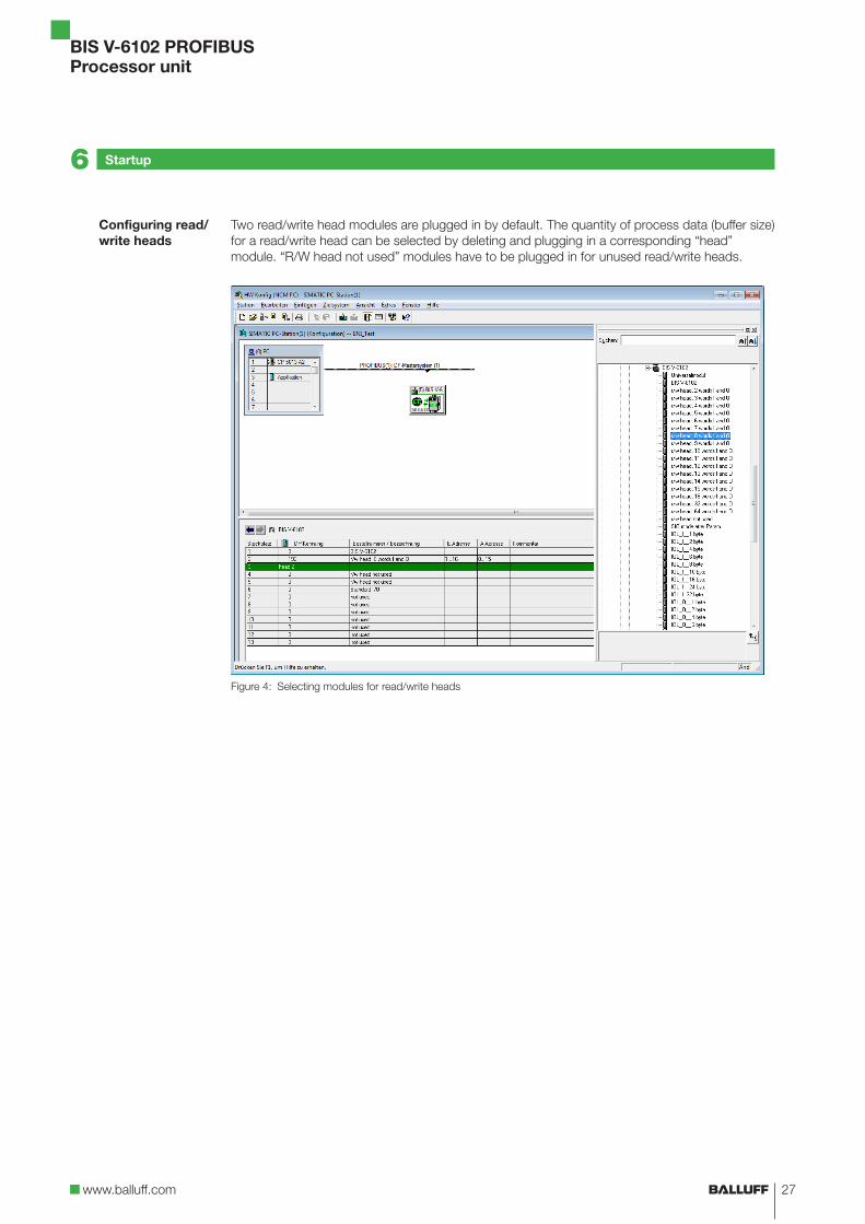
Two read/write head modules are plugged in by default. The quantity of process data (buffer size) for a read/write head can be selected by deleting and plugging in a corresponding “head” module. “R/W head not used” modules have to be plugged in for unused read/write heads.
Figure 4: Selecting modules for read/write heads
Configuring read/write heads
6 Startup

BIS V-6102 PROFIBUSProcessor unit
28
If a IO-Link module is to be installed, the standard I/O module has to be deleted first.
► Select the corresponding IO-Link module after the deletion.
Figure 5: Selecting the IO-Link module
► Drag the selected module to slot 6 (slots 7–13 are reserved for optional additional modules for IO-Link).
Figure 6: Plugging in the IO-Link module
Configuring the IO-Link module
6 Startup

www.balluff.com
BIS V-6102 PROFIBUSProcessor unit
29
Two buffers are needed to exchange data and commands between the processor unit and the host system (input buffer and output buffer). The buffer contents are exchanged using cyclical polling. The buffer content depends on the cycle in which it is written (e.g. control commands at the beginning of a job). When writing the buffer, the sent data from the preceding cycle are overwritten. Unwritten bytes are not deleted and retain their data content.
Example:Total buffer size 80 bytes (4 × 16 bytes: heads H1 to H4, 16 bytes: IO-Link)
1
2
3
4
5
11…1Ehex
21…2Ehex
31…3Ehex
40…4Fhex
01…0Ehex
00hex
0Fhex
10hex
1Fhex
20hex
2Fhex
30hex
3Fhex
The total buffer size is derived from the sum of all buffers (ranges 1–5 + X) and is not allowed to exceed 244 bytes.
The process data buffer is divided into multiple ranges:– Range 1 to 4 = read/write heads 1 to 4 (H1 to H4)– Range 5 = IO-Link– Potential additional ranges for IO-Link
The size of these ranges can be configured using the GSD file.
Figure 1: Example for a total buffer size of 80 bytes (4 × 16 bytes: heads H1 to H4, 16 bytes: IO-Link)
1 R/W head 1 4 R/W head 4
2 R/W head 2 5 IO-Link
3 R/W head 3 Subsequently, potential additional ranges for IO-Link.
IO-Link data is transmitted unchanged to the IO-Link slave via the IO-Link master. IO-Link buffer: 0 to 32 bytes (max.)
7.1 Function Principle of the BIS V-6102
IO-Link
7 Device Function

BIS V-6102 PROFIBUSProcessor unit
30
The control commands for the identification system and the data to be written to the data carrier are sent via the output buffer.
Bit No.
Subaddress7 6 5 4 3 2 1 0
00hex = bit string TI KA GR AV01hex Command designator or Data02hex Start address (Low Byte) or program No. or Data03hex Start address (high byte) or Data04hex Number of bytes (low byte) or Data05hex Number of bytes (high byte) or Data06hex Data… DataLast byte = bit string TI KA GR AV
Assignment and explanation
Subaddress Bit name Meaning Function description
00hex/last byte
TI Toggle bit in Controller is ready to receive additional data (read job).
KA Head shutoff Shuts off the R/W head’s antenna. Tag detection no longer takes place. CP and MT are 0.
GR Basic state Cancels the current job for this R/W head and puts the channel into a basic state. The R/W head can then be used again once GR = 0 and the controller has acknowledged this with BB = 1. CP and MT are 0.
AV Job A job is present.
Command designator 00hex: No command present
Subaddress Meaning Function description
00hex 1st bit string
00hex Command designa-tor
00hex: No command present.
… None No meaning
Last byte 2nd bit string Valid data is present if the 1st and 2nd bit strings match.
7.2 Process Data Buffer
Output buffer
Command structure
7 Device Function

www.balluff.com
BIS V-6102 PROFIBUSProcessor unit
31
Command designator 01hex: Read from data carrier
Subaddress Meaning Function description
00hex 1st bit string
01hex Command designa-tor
01hex: Read from data carrier.
02hex Start address (low byte)
Start address for reading.
03hex Start address (high byte)
Start address for reading.
04hex Number of bytes (low byte)
The number of bytes that are to be read starting from the start address (low byte).
05hex Number of bytes (high byte)
The number of bytes that are to be read starting from the start address (high byte).
… None No meaning
Last byte 2nd bit string Valid data is present if the 1st and 2nd bit strings match.
Command designator 02hex: Write to data carrier
Subaddress Meaning Function description
00hex 1st bit string
01hex Command designa-tor
02hex: Write to data carrier.
02hex Start address (low byte)
Start address to be written from.
03hex Start address (high byte)
Start address to be written from.
04hex Number of bytes (low byte)
The number of bytes that are to be written starting from the start address (low byte).
05hex Number of bytes (high byte)
The number of bytes that are to be written starting from the start address (high byte).
… None No meaning
Last byte 2nd bit string Valid data is present if the 1st and 2nd bit strings match.
Data is accepted from the processor unit only after the command has been accepted by the processor unit and acknowledged.
00hex 1st bit string
01hex Data Transmission of the data which is to be written to the data carrier.
… Data Transmission of the data which is to be written to the data carrier.
Last byte 2nd bit string Valid data is present if the 1st and 2nd bit strings match.
Command structure
7 Device Function

BIS V-6102 PROFIBUSProcessor unit
32
Command designator 03hex: Display output
Subaddress Meaning Function description
00hex 1st bit string
01hex Command designa-tor
03hex: Display output
02hex Data Characters for display output.
… Data Characters for display output.
Last byte 2nd bit string Valid data is present if the 1st and 2nd bit strings match.
Command designator 07hex: Store the start address for the “Auto Read” function
Subaddress Meaning Function description
00hex 1st bit string
01hex Command designa-tor
07hex: Store the start address for the “Auto Read” func-tion in EEPROM.
02hex Start address (low byte)
Address for the “Auto Read” function starting from which the data carrier is read. The value is stored in the EEPROM.
03hex Start address (high byte)
Address for the “Auto Read” function starting from which the data carrier is read. The value is stored in the EEPROM.
… None No meaning
Last byte 2nd bit string Valid data is present if the 1st and 2nd bit strings match.
Command designator 09hex: Type and serial number
Subaddress Meaning Function description
00hex 1st bit string
01hex Command designa-tor
09hex: Read the read/write head type, data carrier type and UID (unique identifier)of a data carrier in the field (for data format, see page 21).
… None No meaning
Last byte 2nd bit string Valid data is present if the 1st and 2nd bit strings match.
Command structure
7 Device Function

www.balluff.com
BIS V-6102 PROFIBUSProcessor unit
33
Command designator 11hex: Copy data between data carriers
Subaddress Meaning Function description
00hex 1st bit string
01hex Command designa-tor
11hex: Copy data carrier.
02hex Source start address (low byte)
Copy the start address of the source data carrier for the function from which copying is to start.
03hex Source start address (high byte)
Copy the start address of the source data carrier for the function from which copying is to start.
04hex Target start address (low byte)
Copy the start address of the target data carrier for the function from which copying is to start.
05hex Target start address (high byte)
Copy the start address of the target data carrier for the function from which copying is to start.
06hex Number of bytes (low byte)
The number of bytes that are to be copied starting from the source start address (low byte).
07hex Number of bytes (high byte)
The number of bytes that are to be copied starting from the source start address (high byte).
08hex Target R/W head number
Number of the read/write head that the target data carrier is in front of.
… None No meaning
Last byte 2nd bit string Valid data is present if the 1st and 2nd bit strings match.
Command designator 12hex: Initialize CRC_16 data check
Subaddress Meaning Function description
00hex 1st bit string
01hex Command designa-tor
12hex: Initialize data carrier.
02hex Start address (low byte)
Start address from which the CRC_16 data check is to be carried out.
03hex Start address (high byte)
Start address from which the CRC_16 data check is to be carried out.
04hex Number of bytes (low byte)
Number of bytes for which a CRC_16 data check is to be carried out from the start address (low byte).
05hex Number of bytes (high byte)
Number of bytes for which a CRC_16 data check is to be carried out from the start address (high byte).
… None No meaning
Last byte 2nd bit string Valid data is present if the 1st and 2nd bit strings match.
Command structure
7 Device Function

BIS V-6102 PROFIBUSProcessor unit
34
Command designator 32hex: Write constant value to data carrier
Subaddress Meaning Function description
00hex 1st bit string
01hex Command designa-tor
32hex: Write a data carrier with a constant value.
02hex Start address (low byte)
Start address to be written from.
03hex Start address (high byte)
Start address to be written from.
04hex Number of bytes (low byte)
The number of bytes that are to be written starting from the start address (low byte).
05hex Number of bytes (high byte)
The number of bytes that are to be written starting from the start address (high byte).
… None No meaning
Last byte 2nd bit string Valid data is present if the 1st and 2nd bit strings match.
Data is accepted from the processor unit only after the command has been accepted by the processor unit and acknowledged.
00hex 1st bit string
01hex Data Value that is to be written to the data carrier.
… None No meaning
Last byte 2nd bit string Valid data is present if the 1st and 2nd bit strings match.
Command structure
7 Device Function

www.balluff.com
BIS V-6102 PROFIBUSProcessor unit
35
The input buffer is used to send the data read from the identification system, the designations and the status codes to the host system.
Bit No.
Subaddress7 6 5 4 3 2 1 0
00hex = bit string BB HF TO MT AF AE AA CP01hex Status code or Data02hex Data… DataLast byte = bit string BB HF TO MT AF AE AA CP
Assignment and explanation
Subaddress Bit name Meaning Function description
00hex/last byte
BB Ready for operation After powering up or after a reset via the GR bit, the BB bit indicates that the correspon-ding channel is ready.
HF Head error Cable break to the R/W head.
TO Toggle bit out Read: Additional data is being provided by the identification system.Write: Identification system can accept additional data.
MT Multiple Tag More than 1 data carrier is in the R/W head’s field.
AF Job error A job was not processed correctly or was canceled.
AE Job End A job was completed without errors.
AA Job Start A job was detected and started.
CP Code present A data carrier has been detected.
Structure of the input bufferThe structure of the process data buffer is identical for all commands.
Subaddress Meaning Function description
00hex 1st bit string
01hex Status code Provides information on the status of a query.
02hex Data Transmission of data which was read from the data carrier.
… Data Transmission of data which was read from the data carrier.
Last byte 2nd bit string Valid data is present if the 1st and 2nd bit strings match.
NoteDisplaying the “multiple tag function” (MT) is not possible with BIS C read/write heads.
Input buffer
7 Device Function

BIS V-6102 PROFIBUSProcessor unit
36
Status codes
NoteStatus codes are only valid in connection with the AF bit!
Status code Function description
00hex Everything OK
01hex Job cannot be run because there is no data carrier in range of the read/write head.
02hex Cannot read the data carrier.
03hex Data carrier was removed from the R/W head’s range during reading.
04hex Cannot write to the data carrier.
05hex Data carrier was removed from the R/W head’s range during writing.
07hex No or invalid command designator with set AV bit or the number of bytes is 00hex.
09hex R/W head cable break or no R/W head connected.
0Dhex Communication to the R/W head disrupted.
0Ehex CRC for the read data and CRC for the data carrier do not agree.
0Fhex 1st and 2nd bit string are unequal. The 2nd bit string must be used.
20hex Address of the read/write job is outside the memory range of the data carrier.
21hex This function is not possible for this data carrier.
Description of the Code Present (CP) and Multiple Tag (MT) bits
CP MT Meaning
0 0 No tag in the field
1 0 Exactly one tag in the field. Automatic reading is OK (if configured).
0 1 More than one data carrier is in the field. They cannot be processed.
1 1 Does not occur.
7 Device Function
www.balluff.com
BIS V-6102 PROFIBUSProcessor unit
37
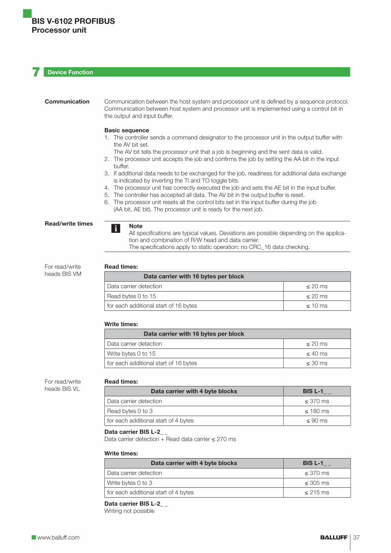
Communication between the host system and processor unit is defined by a sequence protocol. Communication between host system and processor unit is implemented using a control bit in the output and input buffer.
Basic sequence1. The controller sends a command designator to the processor unit in the output buffer with
the AV bit set. The AV bit tells the processor unit that a job is beginning and the sent data is valid.
2. The processor unit accepts the job and confirms the job by setting the AA bit in the input buffer.
3. If additional data needs to be exchanged for the job, readiness for additional data exchange is indicated by inverting the TI and TO toggle bits.
4. The processor unit has correctly executed the job and sets the AE bit in the input buffer.5. The controller has accepted all data. The AV bit in the output buffer is reset.6. The processor unit resets all the control bits set in the input buffer during the job
(AA bit, AE bit). The processor unit is ready for the next job.
NoteAll specifications are typical values. Deviations are possible depending on the applica-tion and combination of R/W head and data carrier.The specifications apply to static operation; no CRC_16 data checking.
Read times:
Data carrier with 16 bytes per block
Data carrier detection ≤ 20 ms
Read bytes 0 to 15 ≤ 20 ms
for each additional start of 16 bytes ≤ 10 ms
Write times:
Data carrier with 16 bytes per block
Data carrier detection ≤ 20 ms
Write bytes 0 to 15 ≤ 40 ms
for each additional start of 16 bytes ≤ 30 ms
Read times:
Data carrier with 4 byte blocks BIS L-1_ _
Data carrier detection ≤ 370 ms
Read bytes 0 to 3 ≤ 180 ms
for each additional start of 4 bytes ≤ 90 ms
Data carrier BIS L-2_ _Data carrier detection + Read data carrier ≤ 270 ms
Write times:
Data carrier with 4 byte blocks BIS L-1_ _
Data carrier detection ≤ 370 ms
Write bytes 0 to 3 ≤ 305 ms
for each additional start of 4 bytes ≤ 215 ms
Data carrier BIS L-2_ _Writing not possible
Communication
Read/write times
For read/write heads BIS VM
For read/write heads BIS VL
7 Device Function

BIS V-6102 PROFIBUSProcessor unit
38
Read times in static mode
Data carrier with 32 bytes per block
No. of bytes Read time [ms]
0 to 31 110
for each additional start of 32 bytes 120
Data carrier with 64 bytes per block
No. of bytes Read time [ms]
0 to 63 220
for each additional start of 64 bytes 230
Write times in static mode
Data carrier with 32 bytes per block
No. of bytes Read time [ms]
0 to 31 110 + n * 10
≥ 32 bytes y * 120 + n * 10
Data carrier with 64 bytes per block
No. of bytes Read time [ms]
0 to 63 220 + n * 10
≥ 64 bytes Y * 230 + n * 10
n = Number of contiguous bytes to writey = Number of bytes to process
Example: 17 bytes should be written starting at address 187. Data carrier block size = 32 bytes. Blocks 5 and 6 are processed, since the start address 187 is in block 5 and end address 203 is in block 6.t = 2 * 120 + 17 * 10 = 410
For read/write heads BIS C
7 Device Function

www.balluff.com
BIS V-6102 PROFIBUSProcessor unit
39
Read times within the first block in dynamic mode
Data carrier with 32 bytes per block
No. of bytes Read time [ms]
0 to 3 14
For each additional byte 3.5
0 to 31 112
Data carrier with 64 bytes per block
No. of bytes Read time [ms]
0 to 3 14
For each additional byte 3.5
0 to 63 224
m = Highest address to readFormula: t = (m + 1) * 3.5 ms
Example: Read 11 bytes starting at address 9. This means that the largest address to be read is 19. This yields 70 ms.
NoteDynamic operation with BIS C: The times indicated apply after the data carrier has been detected. Otherwise 45 ms must be added for powering up until the data carrier is recognized. To achieve the read times specified in dynamic operation, the Tag Type parameter has to be set to “BIS C 32 Byte” or “BIS C 64 Byte” on the respective head.
7 Device Function
BIS V-6102 PROFIBUSProcessor unit
40
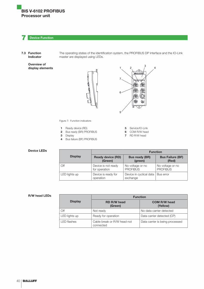
The operating states of the identification system, the PROFIBUS DP interface and the IO-Link master are displayed using LEDs.
1 2 4
5
6
7
3
Figure 7: Function indicators
1 Ready device (RD) 5 Service/IO-Link2 Bus ready (BR) PROFIBUS 6 COM R/W head3 Display 7 RD R/W head4 Bus failure (BF) PROFIBUS
DisplayFunction
Ready device (RD)(Green)
Bus ready (BR) (green)
Bus Failure (BF)(Red)
Off Device is not ready for operation
No voltage or no PROFIBUS
No voltage or no PROFIBUS
LED lights up Device is ready for operation
Device in cyclical data exchange
Bus error
DisplayFunction
RD R/W head(Green)
COM R/W head(Yellow)
Off Not ready No data carrier detected
LED lights up Ready for operation Data carrier detected (CP)
LED flashes Cable break or R/W head not connected
Data carrier is being processed
7.3 Function Indicator
Overview of display elements
Device LEDs
R/W head LEDs
7 Device Function
www.balluff.com
BIS V-6102 PROFIBUSProcessor unit
41
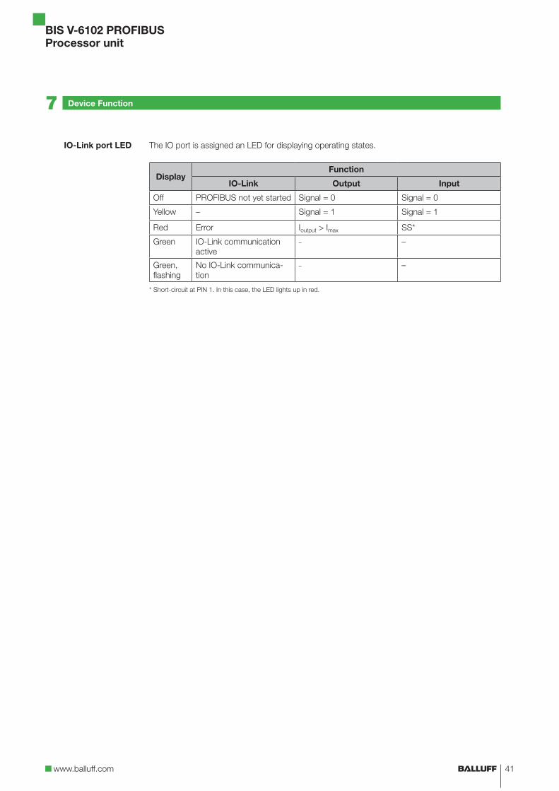
The IO port is assigned an LED for displaying operating states.
DisplayFunction
IO-Link Output Input
Off PROFIBUS not yet started Signal = 0 Signal = 0
Yellow – Signal = 1 Signal = 1
Red Error Ioutput > Imax SS*
Green IO-Link communication active
– –
Green, flashing
No IO-Link communica-tion
– –
* Short-circuit at PIN 1. In this case, the LED lights up in red.
IO-Link port LED
7 Device Function

BIS V-6102 PROFIBUSProcessor unit
42
1. Reading 30 bytes at R/W head 1, start address 10
Once enough data has been read to fill the input buffer of the R/W head 1 while running the reading job, the data will be carried over to the input buffer. The AE bit is not set until the proces-sor unit has finished the “Read” operation.The reply “Job End” (AE bit) is reliably set no later than before the last data has been sent. This time point depends on the requested volume of data and the time response of the controller. In the example the italic format “Set AE bit” calls your attention to this fact.
Controller Identification system
1. Process output buffer (note sequence):
2. Process input buffer: (note sequence):
01hex Command designator 01hex
00hex/0Fhex Set AA bit
02hex Start address 0Ahex 01…0Ehex Enter first 14 bytes
03hex Start address 00hex 00hex/0Fhex Invert TO bit
04hex No. of bytes 1Ehex 00hex/0Fhex Set AE bit
05hex No. of bytes 00hex
00hex/0Fhex Set AV bit
3. Process input buffer: 4. Process input buffer:
01…0Ehex Copy first 14 bytes 01…0Ehex Enter second 14 bytes
Process output buffer: 00hex/0Fhex Invert TO bit
00hex/0Fhex Invert TI bit 00hex/0Fhex Set AE bit
5. Process input buffer: 6. Process input buffer:
01…0Ehex Copy second 14 bytes 01…02hex Enter last bytes
Process output buffer: 00hex/0Fhex Invert TO bit
00hex/0Fhex Invert TI bit 00hex/0Fhex Set AE bit
7. Process input buffer: 8. Process input buffer:
01…02hex Copy last bytes 00hex/0Fhex Reset AA and AE bits
Process output buffer:
00hex/0Fhex Reset AV bit
7.4 Examples
7 Device Function

www.balluff.com
BIS V-6102 PROFIBUSProcessor unit
43
2. Reading 30 bytes at R/W head 1, start address 10, problem during reading
NoteIf a problem occurs, the AF bit is set with the corresponding status number instead of the AE bit. Setting the AF bit cancels the job and declares it as finished.
Controller Identification system
1. Process output buffer (note sequence):
2. Process input buffer: (note sequence): If problem occurs immediately!
01hex Command designator 01hex
00hex/0Fhex Set AA bit
02hex Start address 0Ahex 01hex Enter status number
03hex Start address 00hex 00hex/0Fhex Set AF bit
04hex No. of bytes 1Ehex
05hex No. of bytes 00hex
00hex/0Fhex Set AV bit
3. Process input buffer: 4. Process input buffer:
01hex Copy status number 00hex/0Fhex Reset AA and AF bits
Process output buffer:
00hex/0Fhex Reset AV bit
7 Device Function

BIS V-6102 PROFIBUSProcessor unit
44
3. Reading 30 bytes at R/W head 1, start address 10, problem during reading
NoteIf a problem occurs after transmission of the data has started, the AF bit is provided instead of the AE bit together with a corresponding status number. The AF status message is dominant. Which data is incorrect cannot be specified. Setting the AF bit cancels the operation and declares it as finished.
Controller Identification system
1. Process output buffer (note sequence):
2. Process input buffer: (note sequence):
01hex Command designator 01hex
00hex/0Fhex Set AA bit
02hex Start address 0Ahex 01…0Ehex Enter first 14 bytes
03hex Start address 00hex 00hex/0Fhex Invert TO bit
04hex No. of bytes 1Ehex
05hex No. of bytes 00hex
00hex/0Fhex Set AV bit
3. Process input buffer: 4. Process input buffer:If a problem has occurred!
01…0Ehex Copy first 14 bytes 01hex Enter status number
Process output buffer: 00hex/0Fhex Set AF bit
00hex/0Fhex Invert TI bit
5. Process input buffer: 6. Process input buffer:
01…0Ehex Copy status number 00hex/0Fhex Reset AA and AF bits
Process output buffer:
00hex/0Fhex Reset AV bit
7 Device Function

www.balluff.com
BIS V-6102 PROFIBUSProcessor unit
45
4. Writing 30 bytes at R/W head 1, start address 20
Controller Identification system
1. Process output buffer (note sequence):
2. Process input buffer: (note sequence):
01hex Command designator 02hex
00hex/0Fhex Set AA bit, invert TO bit
02hex Start address 14hex
03hex Start address 00hex
04hex No. of bytes 1Ehex
05hex No. of bytes 00hex
00hex/0Fhex Set AV bit
3. Process output buffer: 4. Process output buffer:
01…0Ehex Enter first 14 bytes 01…0Ehex Copy first 14 bytes
00hex/0Fhex Invert TI bit Process input buffer:
00hex/0Fhex Invert TO bit
5. Process output buffer: 6. Process output buffer:
01…0Ehex Enter second 14 bytes 01…0Ehex Copy second 14 bytes
00hex/0Fhex Invert TI bit Process input buffer:
00hex/0Fhex Invert TO bit
7. Process output buffer: 8. Process output buffer:
01…02hex Enter last 2 bytes 01…02hex Copy last 2 bytes
00hex/0Fhex Invert TI bit Process input buffer:
00hex/0Fhex Set AE bit
9. Process output buffer: 10. Process input buffer:
00hex/0Fhex Reset AV bit 00hex/0Fhex Reset AA and AE bits
7 Device Function

BIS V-6102 PROFIBUSProcessor unit
46
5. Copying data from one data carrier to another
The data from one data carrier at a read/write head (source) is copied to a data carrier in front of another read/write head (target). The data carriers have to be in front of the read/write heads (even if dynamic mode has been configured) and must have the specified address range. The command is processed in the buffer of the source head.
In the example, 17 bytes starting from address 10 of the data carrier are to be copied to the data carrier in front of read/write head 3 starting from address 35.
Controller Identification system
1. Process output buffer (note sequence):
2. Process input buffer: (note sequence):
01hex Command designator 11hex
00hex/0Fhex Set AA bit, Set AE bit
02hex Source start address 0Ahex
03hex Source start address 00hex
04hex Target start address 23hex
05hex Target start address 00hex
06hex No. of bytes 11hex
07hex No. of bytes 00hex
08hex Target head number 03hex
00hex/0Fhex Set AV bit
3. Process output buffer: 4. Process input buffer:
00hex/0Fhex Reset AV bit 00hex/0Fhex Reset AA and AE bits
7 Device Function

www.balluff.com
BIS V-6102 PROFIBUSProcessor unit
47
6. Writing a data carrier with a constant value
A data carrier is to be written with 1000 bytes (constant value) starting from start address 80.
Controller Identification system
1. Process output buffer (note sequence):
2. Process input buffer: (note sequence):
01hex Command designator 32hex
00hex/0Fhex Set AA bit, invert TO bit
02hex Start address 50hex
03hex Start address 00hex
04hex Number of bytes E8hex
05hex No. of bytes 03hex
00hex/0Fhex Set AV bit
3. Process output buffer: 4. Process output buffer:
01 Enter constant value 01 Copy constant value
00hex/0Fhex Invert TI bit Process input buffer:
00hex/0Fhex Set AE bit
5. Process output buffer: 6. Process input buffer:
00hex/0Fhex Reset AV bit 00hex/0Fhex Reset AA and AE bits
7 Device Function

BIS V-6102 PROFIBUSProcessor unit
48
7. Initializing a data carrier for CRC
The sequence for CRC initialization is similar to a write command. The start address and number of bytes must correspond to the maximum volume of data used.In the example the complete memory area of a data carrier (752 bytes) is used. 658 bytes on the data carrier are available as data bytes, since 94 bytes are required for the CRC.
Controller Identification system
1. Process output buffer (note sequence):
2. Process input buffer: (note sequence):
01hex Command designator 12hex
00hex/0Fhex Set AA bit, invert TO bit
02hex Start address 00hex
03hex Start address 00hex
04hex No. of bytes 92hex
05hex No. of bytes 02hex
00hex/0Fhex Set AV bit
3. Process output buffer: 4. Process output buffer:
01…0Ehex Enter first 14 bytes 01…0Ehex Copy first 14 bytes
00hex/0Fhex Invert TI bit Process input buffer:
00hex/0Fhex Invert TO bit
5. Process output buffer: 6. Process output buffer:
01…0Ehex Enter second 14 bytes 01…0Ehex Copy second 14 bytes
00hex/0Fhex Invert TI bit Process input buffer:
00hex/0Fhex Invert TO bit
95. Process output buffer: 96. Process output buffer:
01…08hex Enter last bytes 01…08hex Copy last bytes
00hex/0Fhex Invert TI bit Process input buffer:
00hex/0Fhex Set AE bit
97. Process output buffer: 98. Process input buffer:
00hex/0Fhex Reset AV bit 00hex/0Fhex Reset AA and AE bits
7 Device Function

www.balluff.com
BIS V-6102 PROFIBUSProcessor unit
49
8. Creating a basic state for a R/W head or switching off a R/W head
The read/write heads for the identification system can be put into a basic state independently of each other and the respective read/write head can be shut off.
Controller Identification system
1. Process output buffer: 2. Go to basic state.Process input buffer:
00hex/0Fhex Set GR bit 00hex/0Fhex Reset BB bit
⇒ R/W head is shut off
3. Process output buffer: 4. Process input buffer:
00hex/0Fhex Reset GR bit 00hex/0Fhex Set BB bit
⇒ R/W head is switched on
9. Switching off a read/write head antenna
During normal operation, all read/write head antennas are switched on. The antenna of a respec-tive R/W head can be switched off by setting the KA bit.
Controller
1. Process output buffer:
00hex/0Fhex Set KA bit
The R/W head’s antenna is switched back on by resetting the KA bit.
7 Device Function

BIS V-6102 PROFIBUSProcessor unit
50
The display provides functions for starting up the BIS V. These can be used to configure the PROFIBUS station address and to output tag data for diagnostic purposes. It is controlled using a 2-button controller. You can navigate within a menu level by holding the Enter/Down and Cancel/Up buttons for a short time. You can switch between menu levels or confirm or cancel an action by pressing the buttons longer.
Display(Gray/black text, Blue backlighting)
Enter/Down button
Cancel/Up button
1
BALLUFFCancel or Enter
2
MainSetupInfoCancel (1 s)
Enter (1 s)
Cancel (1 s)
4
Address
126
Enter (1 s)
3
SetupAddress
Cancel (1 s)
► You switch through the positions (1st, 2nd, 3rd) using Enter/Down. ⇒ The current position starts flashing.
► Press Cancel/Up to increase the number at the currently selected position. ► Pressing Cancel (1 s) cancels the configuration.
⇒ Back to 4; the currently configured station address is shown. ► Press Enter (1 s) to confirm the configured address.
5
Savenewaddress?
Enter (1 s)
6
Deviceresetsnow!
⇒ A device reset is carried out (after restart: Back to 1)
Cancel (1 s)
Back to 4 (see above)
7.5 Display
Setting the station address
7 Device Function

www.balluff.com
BIS V-6102 PROFIBUSProcessor unit
51
1
BALLUFFCancel or Enter
2
MainSetupInfoCancel (1 s)
Enter Cancel
4
InfoTag IDVersion
Enter (1 s)
3
MainSetupInfoCancel (1 s)
Enter (1 s)
Cancel (1 s)
Cancel (1 s)
5
ID, Head 1E0 08 01 D7E5 47 5D 55
Cancel
6
ID, Head 2E0 08 01 D7E5 47 5D 56Enter
Display of the ID of the data carrier in front of read head 1
Display of the ID of the data carrier in front of read head 2
When selecting Head_IDs 1 to 4 (5, 6, etc.), you can hold down Cancel for 1 s to return to 4.
Displaying tag data
7 Device Function

BIS V-6102 PROFIBUSProcessor unit
52
7 Device Function
1
BALLUFFCancel or Enter
2
MainSetupInfoCancel (1 s)
Enter Cancel
4
InfoTag IDVersion
Enter (1 s)
3
MainSetupInfoCancel (1 s)
Enter Cancel
5
InfoTag IDVersion
Enter (1 s)
6
Vers. InfoFW: 1.00IOL: 010A
Cancel (1 s)
Two versions are displayed:– The firmware version of the device (here 1.00)– The software version of the IO-Link firmware (010A)
Version display

www.balluff.com
BIS V-6102 PROFIBUSProcessor unit
53
The diagnostics telegram comprises various blocks. The first 6 bytes (standard diagnostics) are defined by PROFIBUS standard EN 50170. If a problem occurs, expanded diagnostics follow. 2 bytes of ID-specific diagnostics, 6 bytes of device-specific diagnostics and then 3 bytes for each group of channel-related diagnostics.A diagnostics telegram consists of at least 6 bytes and at most 244 bytes.
Byte Bit
7 6 5 4 3 2 1 0
0 Status 1
1 Status 2
2 Status 3
3 Master address
4 Ident_Number_High_Byte0Dhex
5 Ident_Number_Low_ByteA9hex
Note!For coding standard-specific diagnostics: 1 = enabled, 0 = disabled.
The coding for bytes 0 to 3 of standard diagnostics is described next. Byte 4 and byte 5 (ID number) are fixed.
Byte 0, status 1:
Bit Meaning
0 Station_non_existentThe DP slave always sets the bit to 0. The DP master sets it to 1 if the DP slave cannot be reached.
1 Station_not_readyThe DP slave sets the bit to 1 if it is not yet ready for data exchange.
2 Cfg faultThe DP slave sets the bit to 1 if the configuration data last received from the master does not agree with that which the DP slave detected.
3 Ext_diagIf the bit is set to 1, there is a diagnostics entry in the slave-specific diagnostics area (Ext_Diag_Data). A further diagnostic follows in the telegram.
4 Not supportedThe DP slave sets the bit to 1 if an unsupported function was requested.
5 Invalid_Slave-ResponseThe DP slave always sets the bit to 0. The master sets it to 1 if it receives an implausi-ble response from the DP slave.
6 Prm_faultThe slave sets the bit to 1 if the last parameter telegram was defective (e.g. wrong length, wrong ID number, invalid parameters).
7 Master_lockThe DP slave always sets the bit to 0. The DP master sets it to 1 if the DP slave was parameterized by a different master (Lock from another master; here: Address in byte 3 not equal to FFhex and not equal to its own address).
8.1 Diagnostics Telegram
Normal diagnostics
Coding of normal diagnostics
Status 1
8 Diagnostics

BIS V-6102 PROFIBUSProcessor unit
54
Byte 1, status 2:
Bit Meaning
0 Prm_reqThe DP slave always sets the bit to 1 if it needs to be reconfigured and paramete-rized. The bit remains set until parameterization has been performed.
1 Stat_Diag (static diagnostics)The slave sets the bit to 1 if, for example, it cannot send valid data. In this case, the DP master retrieves diagnostic data until the bit is reset to 0.
2 Fixed at 1
3 WD_OnResponse monitoring enabled/disabled (watchdog on).
4 Freeze_ModeThe slave sets the bit to 1 if it has received the Freeze command.
5 Sync_ModeThe slave sets the bit to 1 if it has received the Sync command.
6 Not_PresentThe DP slave always sets the bit to 0. The DP master sets it to 1 for DP slaves not contained in the master parameter set.
7 DeactivatedThe DP slave always sets the bit to 0. The DP master sets it to 1 if the DP slave is removed from the master parameter set.
Byte 2, status 3:
Bit Meaning
0…6 Reserved
7 Ext_Diag_OverflowIf this bit is set, there is more diagnostics information than indicated in Ext_Diag_Data.For example, the DP slave sets the bit to 1 if there is more channel-related diagnostic information than the DP slave can enter in its send buffer.A DP master sets the bit to 1 if the DP slave sends more diagnostics information than the master can hold in its diagnostics buffer.
Byte 3, address of the master:
Bit Meaning
0…7 Master_AddAfter configuring parameters, the address of the DP master that configured the parameters for the DP slave is entered. If a DP slave’s parameters were not confi-gured by a master, it sets address FFhex.
Byte 4, ident high:
Bit Meaning
0…7 0Dhex
Byte 4, ident high:
Bit Meaning
0…7 A9hex
Status 2
Status 3
Address
Ident_Number_High_Byte
Ident_Number_Low_Byte
8 Diagnostics

www.balluff.com
BIS V-6102 PROFIBUSProcessor unit
55
Invalid data, defect in module:
Slot Header +
number of bytes
in the diagnos-
tics
Alarm or status type
Slot number
Status or alarm specifier
Status messages
S7Descrip-
tion
1st byte 2nd byte 3rd byte 4th byte 5th byte 6th byte
Slot 6 IO-Link pin 4
06hex 82hex 00hex 00hex 00hex 04hex
Invalid data, wrong module:
Slot Header +
number of bytes
in the diagnos-
tics
Alarm or status type
Slot number
Status or alarm specifier
Status messages
S7Descrip-
tion
1st byte 2nd byte 3rd byte 4th byte 5th byte 6th byte
Slot 6 IO-Link pin 4
06hex 82hex 00hex 00hex 00hex 08hex
Invalid data, missing module:
Slot Header +
number of bytes
in the diagnos-
tics
Alarm or status type
Slot number
Status or alarm specifier
Status messages
S7Descrip-
tion
1st byte 2nd byte 3rd byte 4th byte 5th byte 6th byte
Slot 6 IO-Link pin 4
06hex 82hex 00hex 00hex 00hex 0Chex
Slot Header + number of bytes in the diagnostics
Module No. 5 has a diagnostic
S7Description
1st byte 2nd byte
Slot 6 IO-Link pin 4 42hex 20hex
Device-specific diagnostics IO-Link module
ID-specific diagnostics IO-Link module
8 Diagnostics

BIS V-6102 PROFIBUSProcessor unit
56
Byte Bit
7 6 5 4 3 2 1 0
0 Header
1 Channel
2 Error
Byte 0, header
Bit Meaning
7…6 Header2: Channel-related diagnostics
5…0 Affected module5: IO-Link port
Byte 1, channel
Bit Meaning
7…6 Type1: Input2: Output3: Input and output
5…0 Number of affected channels in the module0: IO-Link port1: IO-Link module
Byte 2, error
Bit Meaning
7…5 Format1: Bit2: 2 bits3: 4 bits
4: Byte5: Word6: 2 words
4…0 Error code1: Short-circuit2: Undervoltage3: Overvoltage4: Overload5: Overtemperature6: Cable break7: Upper limit exceeded8: Lower limit not reached9: Error
10–15: Reserved16–22: Manufacturer-specific23: Actuator warning24: Actuator short circuit25: Low voltage bus/sensor supply26: External diagnostic27: Sensor has wrong configuration28: Low voltage actuator supply29–31: Manufacturer-specific
Channel-related diagnostics
Coding of channel-related diagnostics
Header
Channel
Error
8 Diagnostics

www.balluff.com
BIS V-6102 PROFIBUSProcessor unit
57
An IO-Link module attached to the IO-Link port with inputs and outputs was removed:
Slot Header and affected module
Channel Error
S7Description
1st byte 2nd byte 3rd byte
Slot 6 IO-Link pin 4 85hex C0hex 06hex
Example
8 Diagnostics

BIS V-6102 PROFIBUSProcessor unit
58
BIS V – 6 1 02 – 019 –C001
Balluff Identification System
Series V (V = variable)
System component6 = Processor unit
Generation (design/material)1 = Generation 1, 2011 housing design, metal
Interface02 = PROFIBUS DP06 = Ethernet/IP08 = PROFINET10 = EtherCAT11 = CC-Link
Software type019 = PROFIBUS DP
Connection systemC001 = Power supply: 5-pin flanged male connector with 7/8" external thread
IO-Link master and USB: 5-pin flanged female connector with M12 internal thread, A-codedPROFIBUS DP input: 5-pin flanged male connector with M12 external thread, B-codedPROFIBUS DP output: 5-pin flanged female connector with M12 internal thread, B-coded4 heads VL/VM and future systems: 5-pin flanged female connector with M12 internal thread, A-coded
C101 = As for C001, also supports BIS C-3… read/write heads (adapter required)
NoteYou can find more accessories for the BIS V-6102-… in the Balluff BIS catalog and at www.balluff.com.
Type code
Accessories(optional, not included)
Appendix

www.balluff.com
BIS V-6102 PROFIBUSProcessor unit
59
Decimal Hex Control code
ASCII Decimal Hex ASCII Decimal Hex ASCII
0 00 Ctrl @ NUL 43 2B + 86 56 V
1 01 Ctrl A SOH 44 2C , 87 57 W
2 02 Ctrl B STX 45 2D - 88 58 X
3 03 Ctrl C ETX 46 2E . 89 59 Y
4 04 Ctrl D EOT 47 2F / 90 5 A Z
5 05 Ctrl E ENQ 48 30 0 91 5B [
6 06 Ctrl F ACK 49 31 1 92 5C \
7 07 Ctrl G BEL 50 32 2 93 5D [
8 08 Ctrl H BS 51 33 3 94 5E ^
9 09 Ctrl I HT 52 34 4 95 5F _
10 0 A Ctrl J LF 53 35 5 96 60 `
11 0B Ctrl K VT 54 36 6 97 61 A
12 0C Ctrl L FF 55 37 7 98 62 B
13 0D Ctrl M CR 56 38 8 99 63 c
14 0E Ctrl N SO 57 39 9 100 64 d
15 0F Ctrl O SI 58 3 A : 101 65 e
16 10 Ctrl P DLE 59 3B ; 102 66 f
17 11 Ctrl Q DC1 60 3C < 103 67 g
18 12 Ctrl R DC2 61 3D = 104 68 h
19 13 Ctrl S DC3 62 3E > 105 69 i
20 14 Ctrl T DC4 63 3F ? 106 6 A j
21 15 Ctrl U NAK 64 40 @ 107 6B k
22 16 Ctrl V SYN 65 41 A 108 6C L
23 17 Ctrl W ETB 66 42 B 109 6D m
24 18 Ctrl X CAN 67 43 C 110 6E n
25 19 Ctrl Y EM 68 44 D 111 6F o
26 1 A Ctrl Z SUB 69 45 E 112 70 p
27 1B Ctrl [ ESC 70 46 F 113 71 q
28 1C Ctrl \ FS 71 47 G 114 72 r
29 1D Ctrl ] GS 72 48 H 115 73 s
30 1E Ctrl ^ RS 73 49 I 116 74 t
31 1F Ctrl _ US 74 4 A J 117 75 u
32 20 SP 75 4B K 118 76 V
33 21 ! 76 4C L 119 77 W
34 22 „ 77 4D M 120 78 X
35 23 # 78 4E N 121 79 Y
36 24 $ 79 4F O 122 7 A Z
37 25 % 80 50 P 123 7B {
38 26 & 81 51 Q 124 7C |
39 27 ‘ 82 52 R 125 7D }
40 28 ( 83 53 S 126 7E ~
41 29 ) 84 54 T 127 7F DEL
42 2 A * 85 55 U
ASCII table
Appendix

BIS V-6102 PROFIBUSProcessor unit
60
AAccessories 58ASCII table 59Auto Read
Standard 21
BBus connection 7
CChecksum 20Communication
Basic sequence 37Control bit
Basic state 30Code present 35Head error 35Job 30, 37Job End 35, 37Job error 35Job Start 35, 37Toggle bit in 30, 37Toggle bit out 35, 37
Control function 7CRC check 20
DData integrity 7Dimensions 11Display elements 40Double bit string 7Dynamic mode 21
EElectrical data 11
FFunction principle 6, 9, 29
IInput buffer 35
Bit string 35Intended Use 5IP address 13
AnyBus IPconfig 13DHCP 13
MMechanical data 11
OOperating conditions 12Output buffer 30
Bit string 30
PProcessor unit
Communication 37Display elements 40Function principle 29Input buffer 35Output buffer 30Total buffer 29
Product description 6, 8, 9
RRead times 37Read/write head
Generate basic state 49turn-off 49
SSafety 5
Commissioning 5Installation 5Operation 5
TTechnical data
Electrical data 11Mechanical data 11Operating conditions 12
Technical DataDimensions 11
Total buffer 29Type code 58Type, serial number 21
WWarning notes
Meaning 5Write times 37
Index

www.balluff.com
Balluff GmbH Schurwaldstraße 973765 Neuhausen a.d.F.GermanyPhone +49 7158 173-0Fax +49 7158 [email protected]
No.
887
555
DE
∙ 14
07; S
ubje
ct to
mod
ifica
tion.
Rep
lace
s 13
07.
www.balluff.com


![Whirlpool Delta Awm 6102 [ET]](https://img.pdfslide.us/doc/110x75/540884fcdab5cac8598b4a9b/whirlpool-delta-awm-6102-et.jpg)