Embed Size (px)
Citation preview

BIS V-6106 Ethernet/IPTechnical Reference, Operating Manual
english

www.balluff.com

www.balluff.com
BIS V-6106 Ethernet/IP™
Processor Unit
3
1 User Instructions 4
1.1 About This Manual 4
1.2 Typographical Conventions 4
1.3 Symbols 4
1.4 Meaning of Warnings 4
1.5 Abbreviations 5
2 Safety 6
2.1 Intended Use 6
2.2 General Safety Notes 6
3 Basic Knowledge 7
3.1 Operating Principle of Identification Systems 7
3.2 Product Description 7
3.3 Control Function 8
3.4 Data Integrity 8
3.5 Read/Write Heads H1…H4 9
3.6 EtherNet/IP™ 9
3.7 IO-Link 10
3.8 USB Port 10
4 Installation 11
4.1 Processor Unit Scope of Delivery 11
4.2 Processor Unit Installation 11
4.3 Electrical Connections 12
5 Technical Data 13
6 Startup 15
6.1 Assemblies 16
6.2 Config Assembly 16
7 Device Functions 24
7.1 Function Principle of the BIS V-6106 24
7.2 Process Data Buffer 25
7.3 Function Indicator 65
7.4 Examples 67
7.5 Display 81
7.6 Webserver 87
Appendix 93
Index 95

BIS V-6106 Ethernet/IP™
Processor Unit
4
This manual describes the processor unit for BIS V-6106 Identification Systems and startup
instructions for immediate operation.
The following conventions are used in this manual:
Action instructions are indicated by a preceding triangle. The result of an action is indicated by
an arrow.
Action instruction 1.
Action result.
Action instruction 2.
Numbers:
– Decimal numerals are shown without an additional indicator (e.g. 123).
– Hexadecimal numerals are shown with the additional indicator hex (e.g. 00hex).
Parameters:
Parameters are shown in italics (e.g. CRC_16).
Directory paths:
References to paths where data is stored or is to be saved are shown in small caps (e.g.
PROJECT:\DATA TYPES\USER-DEFINED).
Control characters:
Control characters for sending are set in angle brackets (e.g. <ACK>).
ASCII code:
Characters transmitted in ASCII code are set in apostrophes (e.g. 'L').
Note, tip
This symbol indicates general notes.
Warning notes are especially safety-relevant and are used for accident avoidance. This
information must be read thoroughly and followed exactly. The warning notes are constructed as
follows:
SIGNAL WORD
Type and source of the hazard
Consequences of non-observance
Measures for hazard avoidance
The signal words used have the following meaning:
NOTICEThe warning word NOTICE indicates a risk which can result in damage to or destruction of
the product.
CAUTIONThe general warning symbol combined with the signal word CAUTION indicates a risk which
can result in slight or moderate injuries.
WARNINGThe general warning symbol combined with the signal word WARNING indicates a risk which
can result in serious injury or death.
DANGERThe general warning symbol combined with the signal word DANGER indicates a risk which
can result directly in serious injury or death.
1.1 About This
Manual
1.2 Typographical
Conventions
Actions
Syntax
1.3 Symbols
1.4 Meaning of
Warnings
1 User Instructions

www.balluff.com
BIS V-6106 Ethernet/IP™
Processor Unit
5
ARP Address Resolution ProtocolBIS Balluff Identification SystemCIP Common Industrial ProtocolCP Code PresentCRC Cyclic Redundancy CheckDHCP Dynamic Host Configuration ProtocolI/O port Digital input and output portEDS Electronic Data SheetEEPROM Electrical Erasable and Programmable ROMEIRP Equivalent Isotropically Radiated PowerEIP EtherNet/IP™EMC Electromagnetic compatibilityEPC Electronic Product CodeERP Effective Radiated PowerFCC Federal Communications CommissionFE Functional groundLF CR Line Feed with Carriage ReturnMAC ID Media Access Controln. c. not connectedODVA Open DeviceNet Vendor AssociationPC Personal ComputerRSSI Receive Signal Strength IndicatorPLC Programmable Logic ControllerTag Data carrierTID Tag identifierUHF Ultra high frequencyUID Unique IdentifierVID Vendor ID
1.5 Abbreviations
1 User Instructions

BIS V-6106 Ethernet/IP™
Processor Unit
6
The BIS V-6106 processor unit is a component of the BIS V identification system. It is used for
linking to a host computer (PLC, PC) within the identification system. It may be used only for this
purpose in an industrial environment corresponding to Class A of the EMC Law.
This reference manual applies to processor units in the following series:
– BIS V-6106-034-C002
– BIS V-6106-034-C102
– BIS V-6106-034-C004
– BIS V-6106-034-C104
Installation and Startup
Installation and startup are to be performed by trained technical personnel only. Any damage
resulting from unauthorized manipulation or improper use voids the warranty and any liability
claims against the manufacturer.
When connecting the processor unit to an external controller, observe proper selection and
polarity for the connection as well as the power supply (see Chapter 4“Installation” on page
11). The processor unit may only be used with an approved power supply (see Chapter 5
“Technical Data” on page 13).
Conformity
This product was developed and manufactured in accordance with the
applicable European directives. CE conformity has been verified.
All approvals and certifications are no longer valid if:
– Components are used that are not part of the BIS V Identification System,
– Components are used that have not been explicitly approved by Balluff.
Operation and testing
The operator is responsible for ensuring that local safety regulations are observed.
In the event of defects and non-correctable faults in the identification system, take the system
out of service and secure it to prevent unauthorized use.
2.1 Intended Use
2.2 General Safety
Notes
2 Safety
www.balluff.com
BIS V-6106 Ethernet/IP™
Processor Unit
7
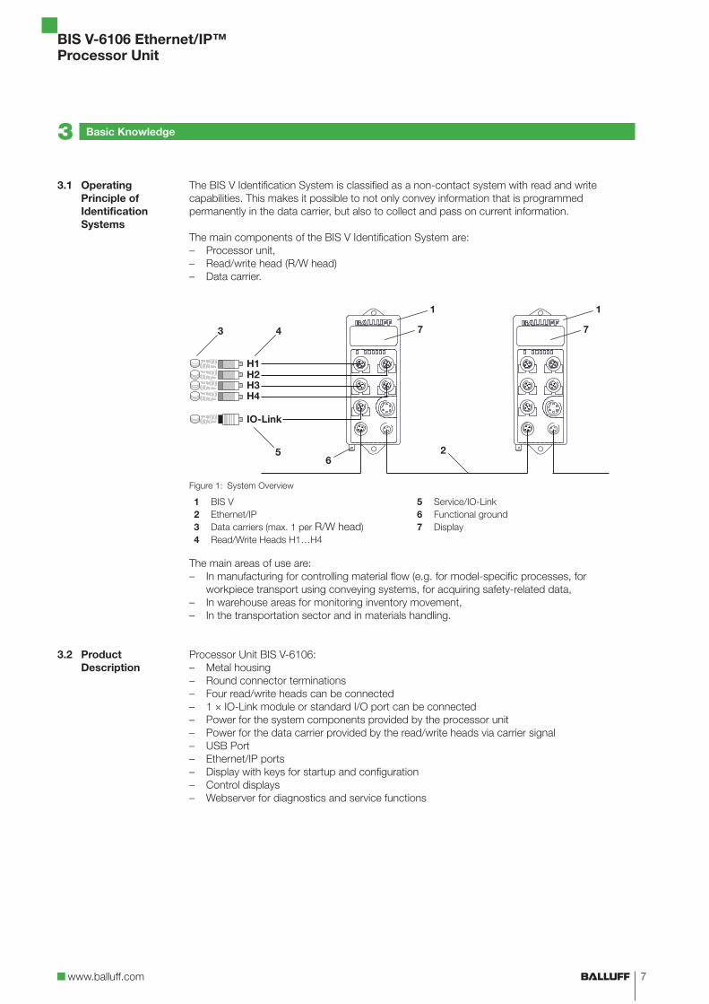
The BIS V Identification System is classified as a non-contact system with read and write
capabilities. This makes it possible to not only convey information that is programmed
permanently in the data carrier, but also to collect and pass on current information.
The main components of the BIS V Identification System are:
– Processor unit,
– Read/write head (R/W head)
– Data carrier.
Figure 1: System Overview
3 4
2
1 1
7 7
56
H1H2H3H4
IO-Link
1
2
3
4
BIS V
Ethernet/IP
Data carriers (max. 1 per R/W head)
Read/Write Heads H1…H4
5
6
7
Service/IO-Link
Functional ground
Display
The main areas of use are:
– In manufacturing for controlling material flow (e.g. for model-specific processes, for
workpiece transport using conveying systems, for acquiring safety-related data,
– In warehouse areas for monitoring inventory movement,
– In the transportation sector and in materials handling.
Processor Unit BIS V-6106:
– Metal housing
– Round connector terminations
– Four read/write heads can be connected
– 1 × IO-Link module or standard I/O port can be connected
– Power for the system components provided by the processor unit
– Power for the data carrier provided by the read/write heads via carrier signal
– USB Port
– Ethernet/IP ports
– Display with keys for startup and configuration
– Control displays
– Webserver for diagnostics and service functions
3.1 Operating
Principle of
Identification
Systems
3.2 Product
Description
3 Basic Knowledge

BIS V-6106 Ethernet/IP™
Processor Unit
8
The processor unit is the link between data carrier and host control system. It manages two-way
data transfer between data carrier and R/W head and provides buffer storage.
The processor unit uses the R/W head to write data from the host control system to the data
carrier or reads the data from the carrier and makes it available to the host control system.
Host control systems could include:
– A control computer (e.g. industrial PC)
– A PLC.
Double Bit Header:
In order to ensure complete transmission of all data in the data buffer, the control bits in the data
buffer's first and last byte (bit header) are transmitted and compared for each R/W head. If both
bit headers are the same, then the data has been fully updated and can be transmitted. This
means that the data for each R/W head is only valid if both bit headers are the same. Thus, the
host control system must also compare the bits in the bit headers.
In order to increase data integrity, data transfer between the data carrier and processor unit and
the storage device must be monitored using a check procedure.
A CRC_16 data check can be enabled for this via parameter configuration.
With the CRC_16 data check, a check code that allows the validity to be checked at any time is
written to the data carrier.
A CRC_16 data check provides the following advantages:
– Data integrity even during the non-active phase (data carrier outside the R/W head).
– Shorter read time – page is read once.
3.3 Control Function
3.4 Data Integrity
3 Basic Knowledge

www.balluff.com
BIS V-6106 Ethernet/IP™
Processor Unit
9
For BIS V-6106-034-C00_, read/write heads in the BIS VM-3 _ _, BIS VL-3 _ _, and BIS VU-3 _ _
series can be connected to terminals H1...H4. BIS V-6106-034-C10_ also supports read/write
heads in the BIS C-3 _ _ series (Adapter required).
Note
Read/write heads in the BIS VU-3 _ _ series are only supported with a device software
version of 3.0 or higher. Should the occasion arise, an update will be required.
Note
Device software as well as manuals with detailed information about the read/write
heads used are available at www.balluff.com.
BIS V processor units are available in different variants with respect to the supported read/write
heads. The following table shows the differences.
Processor Unit Available Connections Compatible Read/Write Heads
H1…H4 VM-3 _ _ VL-3 _ _ VU-3 _ _ C-3 _ _
BIS V-6106-034-C002 H1…H4 YES YES YES NO
BIS V-6106-034-C102 H1…H4 YES YES YES YES
Note
Only shielded cables are to be used for connecting read/write heads!
An adapter cable is required for connecting read/write heads in the BIS C-3_ _ series.
The maximum cable length for read/write heads in the BIS VM-3 _ _, BIS VL-3 _ _,
and BIS VU-3 _ _ series is 50 m. For the BIS C-3 _ _ series, the cable length is set at
1 m, 5 m, or 10 m plus the adapter depending on the design of the system.
Note
Visit www.balluff.com for more information on available software and accessories.
Ethernet/IP is an industrial networking standard. The IP in Ethernet/IP stands for "Industrial
Protocol". Ethernet/IP uses the "Common Industrial Protocol" (CIP) open communication
protocol at the application tier (in accordance with ISO/OSI reference model).
Ethernet/IP is supported by the "Open DeviceNet Vendor Association" (ODVA) network
organization.
3.5 Read/Write
Heads H1…H4
3.6 EtherNet/IP™
3 Basic Knowledge

BIS V-6106 Ethernet/IP™
Processor Unit
10
IO-Link is defined as a standardized point-to-point connection between sensors/actuators and
an I/O module. An IO-Link sensor/actuator can send additional communication data
(e.g. diagnostics signals) in addition to the binary process signals over the IO-Link interface.
Compatibility with standard I/O:
– IO-Link sensors/actuators can be connected to existing I/O modules.
– Sensors/actuators that are not IO-Link-capable can be connected to an IO-Link module.
– Standard sensor/actuator cables can be used
Key technical data:
– Serial point-to-point connection
– Communication as an add-on to the standard I/O
– Standard I/O connection technology, unshielded, 20 m cable length
– Communication using 24 V pulse modulation, standard UART protocol
The device can be connected to a computer's USB port using the "Service/IO-Link" jack and
then behaves like a USB stick. This allows access to the internal memory, where the manual, the
GSD file and a communications driver for service functions are saved. In addition, the BIS V has
to be connected to a voltage source. The communication driver can be installed as needed, but
is not required for the USB port and BIS V to function.
Note
Visit www.balluff.com for more information on available software and accessories.
3.7 IO-Link
3.8 USB Port
3 Basic Knowledge

www.balluff.com
BIS V-6106 Ethernet/IP™
Processor Unit
11
Included in the scope of delivery:
– BIS V-6106
– 5 × closure cap
– Safety Precautions
Note
Visit www.balluff.com for more information on available software and accessories.
Figure 1: Mechanical connection (dimensions in mm)
Figure 2: Installation examples (A: attachment to DIN rails, B: attachment to T-slotted framing)
1
2
DIN rail
Fastening
3
4
T-slotted framing
Holder for screw mounting
Select a suitable installation position.
Secure the processor unit using two M5 screws (strength category 8.8, lightly oiled,
tightening torque M = 5.5 Nm).
4.1 Processor Unit
Scope of Delivery
4.2 Processor Unit
Installation
4 Installation

BIS V-6106 Ethernet/IP™
Processor Unit
12
Note
Make the ground connection either directly or using an RC combination to ground.
Connections
H1…H4 Read/Write Heads
Service/IO-Link USB function
Service/IO-Link
(master function)
EIP1 Ethernet/IP Port 1
EIP2 Ethernet/IP Port 2
FE Functional ground
Figure 3: Electrical Connections
H1…H4
M12 female, 5-pin, A-coded
EIP port 1/2
M12 female, 4-pin, D-coded
PIN Function
1 +24 V DC
2 A
3 0 V
4 B
5 n.c.
PIN Function
1 +Tx
2 +Rx
3 –Tx
4 –Rx
IO-Link / Service
M12 female, 5-pin, A-coded
IO-Link
PIN Function
1 VP (+24 V DC)
2 n. c.
3 0 V
4 Q/C (IO-Link) or
digital input,
optional: output
5 n. c.
Service/USB
PIN Function
1 n. c.
2 USB–
3 0 V
4 n. c.
5 USB+
Power (BIS V-6106-034-C_02)
7/8" male, 5-pin
Power (BIS V-6106-034-C_04)
4-pin 7/8" male
PIN Function
1 0 V
2 0 V
3 FE
4 +24 V DC
5 Reserved, not
connected
PIN Function
1 0 V
2 0 V
3 n.c.
4 +24 V DC
4.3 Electrical
Connections
4 Installation
www.balluff.com
BIS V-6106 Ethernet/IP™
Processor Unit
13
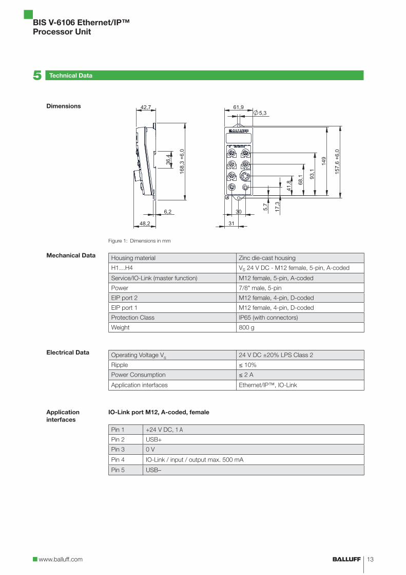
Figure 1: Dimensions in mm
Housing material Zinc die-cast housing
H1…H4 VS 24 V DC - M12 female, 5-pin, A-coded
Service/IO-Link (master function) M12 female, 5-pin, A-coded
Power 7/8" male, 5-pin
EIP port 2 M12 female, 4-pin, D-coded
EIP port 1 M12 female, 4-pin, D-coded
Protection Class IP65 (with connectors)
Weight 800 g
Operating Voltage VS
24 V DC ±20% LPS Class 2
Ripple ≤ 10%
Power Consumption ≤ 2 A
Application interfaces Ethernet/IP™, IO-Link
IO-Link port M12, A-coded, female
Pin 1 +24 V DC, 1 A
Pin 2 USB+
Pin 3 0 V
Pin 4 IO-Link / input / output max. 500 mA
Pin 5 USB–
Dimensions
Mechanical Data
Electrical Data
Application
interfaces
5 Technical Data

BIS V-6106 Ethernet/IP™
Processor Unit
14
Ambient Temperature 0 °C…+60 °C
Storage Temperature 0 °C…+60 °C
EMC (BIS V-6106-034-C00_)
– EN 61000-6-2
– EN 61000-4-2/4/5/6 – Severity level 2A/3A/2A/3A
– EN 61000-4-3
80 MHz – 1000 MHz – Severity level 3A
1400 MHz – 2000 MHz – Severity level 3A
2000 MHz – 2700 MHz – Severity level 2A
– Emission as per EN 55016-2-3 – EN61000-6-4
EMC (BIS V-6106-034-C10_)
– EN 300330-2
– EN 61000-4-2/4/5/6 – Severity level 2A/2A/1A/2A
– EN 61000-4-3
80 MHz – 1000 MHz – Severity level 3A
1400 MHz – 2000 MHz – Severity level 3A
2000 MHz – 2700 MHz – Severity level 2A
– Emission as per EN 301489-1/-3 – EN 55022 (class A)
Vibration/shock EN 60068 Part 2-6/27
Operating
conditions
5 Technical Data

www.balluff.com
BIS V-6106 Ethernet/IP™
Processor Unit
15
The BIS V-6106 processor unit and the controlling system communicate via Ethernet/IP™
protocol.
The Ethernet/IP™ system consists of the following components:
– Ethernet/IP™ scanner
– Ethernet/IP™ adapter (the BIS V-6106 processor unit in this case)
The processor unit and the controlling system communicate using Ethernet/IP. Assigning a
unique IP address associates the processor unit with a network.
A processor unit can be integrated into a network in different ways (DHCP, BootP, ARP). A MAC
address provides the basis for integration into a network. This hardware address is unique and
distinctly identifies network devices such as the processor unit.
Dynamic Host Configuration Protocol (DHCP) allows for dynamic assignment of an IP address
using a server. The hardware can be integrated into the network without requiring any further
configuration. Only automatic assignment (MAC address) of the IP address needs to be
configured.
All device perimeters for configuration are listed in the EDS file. An exact description of the
parameters can be found under point 6.2 on page 16.
EtherNet/IP™
IP Address
DHCP
EDS file
6 Startup

BIS V-6106 Ethernet/IP™
Processor Unit
16
Assemblies Instance ID Data length
INPUT 100 308
OUTPUT 101 292
CONFIG 102 60
Byte Parameter Description
00–01 Device General configuration of the entire device
02–09 RFID Head 1 Configuration of read/write head 1
10–17 RFID Head 2 Configuration of read/write head 2
18–25 RFID Head 3 Configuration of read/write head 3
26–33 RFID Head 4 Configuration of read/write head 4
34–59 IO-Link Port Configuration of the IO-Link port
Byte Meaning
00 HMI read only
01 Device LEDs off
Byte Meaning
02 CRC
03 Dynamic mode*
04 Type serial number
05 Slow tag detection*
06 Low antenna power*
07 Head LEDs off
08 UID Compare Count (only BIS VL-3 _ _)
09 Tag type
* Not for read/write heads BIS VU-3_ _
Byte Meaning
10–17 Same as RFID Head 1 parameter
Byte Meaning
18–25 Same as RFID Head 1 parameter
Byte Meaning
26–33 Same as RFID Head 1 parameter
6.1 Assemblies
6.2 Config Assembly
Device Parameter
RFID Head 1
parameter
RFID Head 2
parameter
RFID Head 3
parameter
RFID Head 4
parameter
6 Startup

www.balluff.com
BIS V-6106 Ethernet/IP™
Processor Unit
17
Byte Meaning
34+35 IO-Link port function
36 Cycle time
37 Validation type
38 IOL Vendor ID 1
39 IOL Vendor ID 2
40 IOL Device ID 1
41 IOL Device ID 2
42 IOL Device ID 3
43 IOL Serial number 1
… …
58 IOL Serial number 16
59 Parameter server
If this function is enabled, the IP configuration settings can no longer be changed via the display.
If this function is enabled, the read/write head LEDs on the BIS V-6106 processor unit are shut
off after 30 min. The parameters for this function are configured in the header module.
IO-Link port
parameter
Description of
individual
parameters
HMI read only
Device LEDs off
6 Startup

BIS V-6106 Ethernet/IP™
Processor Unit
18
The CRC check is a procedure for determining a check value for data in order to be able to
recognize transmission errors. If the CRC check is enabled, a status message will be sent when
a CRC error is detected.
Note
The CRC check function is only supported by read/write heads in the BIS C, BIS VL,
and BIS VM series.
Initializing
To use the CRC check, the data carrier has to be initialized. The data carrier is initialized in the
output buffer using the 12hex command identifier. If the data carrier does not contain the correct
CRC, the processor unit sets an error message in the input buffer (see Example 7 on page
73).
Data carriers as shipped from the factory can be written with a checksum immediately, since all
data is set to 0.
Checksum
M and L system:
The checksum is written to the data carrier as 2 bytes of information. 2 bytes per block are lost.
This leaves 14 bytes per block available. The usable number of bytes can be found in the
following table.
C system:
The checksum is written to the data carrier as 2 bytes of information per page. 2 bytes per page
are lost, i.e. the page size is 30 bytes or 62 bytes depending on the data carrier type.
CRC check
6 Startup

www.balluff.com
BIS V-6106 Ethernet/IP™
Processor Unit
19
The number of usable bytes thus decreases when using the checksum.
Balluff data carrier type Memory capacity Usable bytes for
CRC_16
BIS M-1_ _-01 752 Byte 658 Byte
BIS M-1_ _-02 2000 Byte 1750 Byte
BIS M-1_ _-03 112 Byte 98 Byte
BIS M-1_ _-04 256 Byte 224 Byte
BIS M-1_ _-05 224 Byte 196 Byte
BIS M-1_ _-06 288 Byte 252 Byte
BIS M-1_ _-07 992 Byte 868 Byte
BIS M-1_ _-08 160 Byte 140 Byte
BIS M-1_ _-09 32 Byte 28 Byte
BIS M-1_ _-10 736 Byte 644 Byte
BIS M-1_ _-11 8192 Byte 7168 Byte
BIS M-1_ _-13 32786 Byte 28672 Byte
BIS M-1_ _-14 65536 Byte 57344 Byte
BIS M-1_ _-15 131072 Byte 114688 Byte
BIS M-1_ _-20 8192 Byte 7168 Byte
BIS L-1_ _-01 192 bytes 168 bytes
BIS L-2_ _-03 5 bytes (read-only) —
BIS L-1_ _-05 192 bytes 168 bytes
BIS C-1_ _-04 511 Byte 450 Byte
BIS C-1_ _-05 1023 Byte 930 Byte
BIS C-1_ _-11 2047 Byte 1922 Byte
BIS C-1_ _-32 8192 Byte 7936 Byte
As soon as the Dynamic Mode function is enabled, the processor unit accepts the read/write job
from the host control system and stores it, regardless of whether a data carrier is in the active
zone of the R/W head or not. If a data carrier enters the active range of the R/W head, the stored
job is run.
Note
To achieve the read times specified on page 63 in dynamic operation, the Tag Type
parameter has to be set to "BIS C 32 Byte" or "BIS C 64 Byte" on the respective
head.
CRC check
Dynamic mode
6 Startup

BIS V-6106 Ethernet/IP™
Processor Unit
20
If this function is enabled, the type of the read/write head as well as the data carrier type and the
serial number (UID = Unique Identifier) for the data carrier are output with the Auto Read function
instead of data. The data is output as soon as the data carrier is in the active zone of the read/
write head. The CP bit is set in the input buffer.
The length of the outputted data is reduced to the configured buffer size as appropriate.
Note about BIS C
BIS C data carriers do not have serial numbers.
Note about BIS VM and BIS VL
BIS M and BIS L data carriers transfer a UID with a length of 4 bytes (e.g. Mifare and
Hitag1) or a UID with a length of 8 bytes (ISO 15693) into the Serial Number field.
Because of this, the data sheet for the data carrier used is to be followed.
Note about BIS VU
BIS U data carriers transfer EPC or TID into the Serial Number field, depending on the
most recently executed command. For BIS VU, 00hex is transferred by default into the
data carrier type field.
Data Format 1 byte 1 byte 1 byte Variable
Meaning Length (number of
bytes including
length)
Read/write head
type
Data Carrier
Type
Serial Number
BIS VU-3… BIS VM-3_ _-001-S4 BIS VL-3_ _-001-S4 BIS C-3…
04 03 02 01
For this option, the antenna on the read/write head is switched on for data carrier detection only
every 200 ms. This function is configured in the respective read/write head module (only BIS
VM).
Transmitting power is reduced when using this parameter. The parameters for this function are
configured in the respective read/write head module and is reserved for future read/write heads.
Note
Information about configuring the transmission power for BIS VU read/write heads
can be found in the manual for the BIS L read/write head.
Manuals are available at www.balluff.com.
This parameter switches off the LEDs on the respective read/write head. This function is
configured in the respective read/write head module (only BIS VM and BIS VU).
This parameter indicates how often the 5-byte ID of a BIS L-1_ _-03 data carrier is imported and
compared before the data carrier is shown as identified. The value default setting is 2. For highly
dynamic applications, this value can be set to 1 (only BIS VL).
Type serial
number
Slow tag
detection
Low antenna
power
Head LEDs off
UID Compare
Count
6 Startup

www.balluff.com
BIS V-6106 Ethernet/IP™
Processor Unit
21
The following data carriers are available for the BIS V-6106 processor unit.
Note
The data carriers contain additional memory ranges for configuration and protected
data. These ranges cannot be processed using the BIS V-6106 processor unit.
Mifare data carriers (for read/write heads BIS VM):
Balluff data carrier
type
Manufacturer Description Memory
capacity
Memory type
BIS M-1_ _-01 NXP Mifare Classic 752 Byte EEPROM
BIS M-1_ _-10 NXP Mifare Classic 736 Byte EEPROM
ISO 15693 data carriers (for read/write heads BIS VM):
Balluff data carrier
type
Manufacturer Description Memory
capacity
Memory
type
BIS M-1_ _-02 Fujitsu MB89R118 2000 Byte FRAM
BIS M-1_ _-03 NXP SL2ICS20 112 Byte EEPROM
BIS M-1_ _-04* Texas Instruments TAG-IT Plus 256 Byte EEPROM
BIS M-1_ _-05* Infineon SRF55V02P 224 Byte EEPROM
BIS M-1_ _-06* EM EM4135 288 Byte EEPROM
BIS M-1_ _-07 Infineon SRF55V10P 992 Byte EEPROM
BIS M-1_ _-08* NXP SL2ICS530 160 Byte EEPROM
BIS M-1_ _-09* NXP SL2ICS500 32 Byte EEPROM
BIS M-1_ _-11 Balluff BIS M-1 8192 Byte FRAM
BIS M-1_ _-13 Balluff BIS M-1 32768 Byte FRAM
BIS M-1_ _-14 Balluff BIS M-1 65536 Byte FRAM
BIS M-1_ _-15 Balluff BIS M-1 161072 Byte FRAM
BIS M-1_ _-20 Fujitsu MB89R112 8192 Byte FRAM
* On request
For read/write heads BIS VL:
Balluff data carrier
type
Manufacturer Description Memory
capacity
Memory type
BIS L-1_ _-01 NXP Hitag1 192 bytes EEPROM
BIS L-2_ _-03 EM EM4x02 5 bytes
(read-only)—
BIS L-1_ _-05 NXP HitagS 192 bytes EEPROM
For read/write heads BIS C (with adapter):
Balluff data carrier
type
Manufacturer Memory
capacity
Memory type Memory
organization
BIS C-1_ _-04 Balluff 511 Byte EEPROM 32-byte blocks
BIS C-1_ _-05 Balluff 1023 Byte EEPROM 32-byte blocks
BIS C-1_ _-11 Balluff 2047 Byte EEPROM 64-byte blocks
BIS C-1_ _-32 Balluff 8192 Byte FRAM 64-byte blocks
Tag type
6 Startup

BIS V-6106 Ethernet/IP™
Processor Unit
22
Note
To achieve the read times specified on page 63 in dynamic operation, the Tag Type
parameter has to be set to "BIS C 32 Byte" or "BIS C 64 Byte" on the respective
head.
For read/write heads BIS VU:
Balluff data carrier type Manufacturer Memory capacity
BIS U-1_ _ Balluff See Data Sheet
Note
The read/write head BIS VU generally supports data carriers regardless of
manufacturer, that meet the standards set by EPCglobal™ Class 1 Generation 2 or
ISO IEC 18000-63.
The IO-Link port of the BIS V-6106 can be operated as a digital standard I/O or as an IO-Link
port.
Configuration options:
– 0: Standard I/O
– 1: IO-Link functionality
The cycle time controls the timing for triggering the IO-Link device. The factory default setting is
0 (Auto). It is recommended that this value be retained.
The cycle time is stored in the IO-Link device (slave) and is detected automatically. Only times
that are slower than the automatically selected times can be set manually.
Whether a connected IO-Link device receives access to the IO-Link master can be controlled
using validation.
Configuration options:
– 0
No validation
– 1 Compatible
Only allows communication to the IO-Link master for devices whose vendor ID (VID) and
device ID (DID) correspond to the configured values.
– 2 Identical
See "1 Compatible"; in addition, the serial number of the IO-Link device is checked
Vendor ID for the IO-Link device (refer to the manual for the device)
Device ID for the IO-Link device (refer to the manual for the device)
Serial number for the IO-Link device (if available; refer to the IO-Link device's type plate)
Tag type
IO-Link port
function
Cycle time
Validation type
IOL Vendor ID
(VID)
IOL Device ID
(DID)
IOL Serial
number, optional
6 Startup

www.balluff.com
BIS V-6106 Ethernet/IP™
Processor Unit
23
Automatic upload (IO-Link slave IO-Link master) or download (IO-Link master IO-Link
slave) can be switched on using this parameter.
For automatic upload, the parameter configuration is read when an IO-Link device is plugged in.
For automatic download, the parameter configuration is transmitted to the device when an
IO-Link device is plugged in.
Background:
The automatic upload makes it possible to read in the parameter configuration of a correctly
configured device when plugging one in. If an IO-Link device has to be replaced, the previously
read in parameter configuration from the old device is transferred to the new device when it is
plugged in.
The "Upload" option can be disabled by having a valid parameter set read.
Configuration options:
– 8Xhex: Switch on
– X1hex: Switch on upload
– X2hex: Switch on download
Parameter server,
optional
6 Startup

BIS V-6106 Ethernet/IP™
Processor Unit
24
Two buffers are needed to exchange data and commands between the processor unit and the
host control system (input buffer and output buffer). The buffer contents are exchanged using
cyclical polling. The buffer content depends on the cycle in which it is written (for example,
control commands at the beginning of a job).
When writing to the buffer, the transmitted data from the previous cycle is overwritten. Unwritten
bytes are not deleted and retain their data content.
Process data input (Assembly 100, T->0)
Instance 100
Data length 308
Bytes 0…63 RFID head 1, 64 bytes
Bytes 64…127 RFID head 2, 64 bytes
Bytes 128…191 RFID head 3, 64 bytes
Bytes 192…255 RFID head 4, 64 bytes
Byte 256 Pin 4 input data (if port was not configured as IO-Link)
Byte 257 Short circuit status
Byte 258 Overload status (only if port was not configured as standard I/O)
Byte 259 Power status:
Bit 0 = No actuator supply
Bit 1 = Sensor power
Bit 2 = Actuator power
Bytes 260…291 IO-Link process data, 32 bytes
Byte 292 IO-Link status
Byte 293 IO-Link error
Bytes 294…295 IO-Link vendor ID, 2 bytes
Bytes 296…298 IO-Link device ID, 3 bytes
Bytes 299…307 IO-Link 3 events for every 3 bytes
Process data output (Assembly 101, 0->T)
Instance 101
Data length 292
Bytes 0…63 RFID head 1, 64 bytes
Bytes 64…127 RFID head 2, 64 bytes
Bytes 128…191 RFID head 3, 64 bytes
Bytes 192…255 RFID head 4, 64 bytes
Byte 256 IO-Link pin 4 output data (if port was not configured as IO-Link)
Byte 257 IO-Link pin 4 restart output after short circuit
Byte 258 Reserved
Byte 259 IO-Link control:
Bit 0 = Red LED on display on
Bit 1 = Green LED on display on
Bit 2 = Display lock/PLC lock
Bytes 260…291 IO-Link process data, 32 bytes
7.1 Function
Principle of the
BIS V-6106
7 Device Functions

www.balluff.com
BIS V-6106 Ethernet/IP™
Processor Unit
25
The control commands for the identification system and the data to be written to the data carrier
are transmitted via the output buffer.
Bit No.
Subaddress7 6 5 4 3 2 1 0
00hex = Bit
HeaderTI KA GR AV
01hex Command Identifier or Data
02hex Start address (Low Byte) or program No. or Data
03hex Start address (high byte) or Data
04hex Number of bytes (low byte) or Data
05hex Number of bytes (high byte) or Data
06hex Data
… Data
Last Byte = Bit
HeaderTI KA GR AV
Assignment and explanation
Subaddress Bit name Meaning Description of Function
00hex/last
byte
TI Toggle Bit In Controller is ready to receive additional data
(read job).
KA Head shutoff Shuts off the R/W head's antenna. Tag
detection no longer takes place. CP and MT
are 0.
GR Default state Cancels the current job for this R/W head
and puts the channel into a basic state. The
R/W head can then be used again once
GR = 0 and the controller has acknowledged
this with BB = 1. CP and MT are 0.
AV Job A job is present.
7.2 Process Data
Buffer
Output buffer
7 Device Functions

BIS V-6106 Ethernet/IP™
Processor Unit
26
The input buffer is used to send the data read from the identification system, the
designations, and the status codes to the host control system.
Bit No.
Subaddress7 6 5 4 3 2 1 0
00hex = Bit
HeaderBB HF TO MT AF AE AA CP
01hex Status code or Data
02hex Data
… Data
Last Byte = Bit
HeaderBB HF TO MT AF AE AA CP
Assignment and explanation
Subaddress Bit name Meaning Description of Function
00hex/last
byte
BB Ready for
Operation
After powering up or after a reset via the GR
bit, the BB bit indicates that the
corresponding channel is ready.
HF Head error Cable break to the R/W head.
TO Toggle Bit Out Read: Additional data is being provided by
the identification system.
Write operation: Identification system can
accept additional data.
MT Multiple Tag More than 1 data carrier is in the R/W
head's field (only in BIS VL and VM).
AF Job Error A job was processed incorrectly or was
canceled.
AE Job End A job was completed without errors.
AA Job Start A job was detected and started.
CP Code Present A data carrier has been detected.
Structure of the input buffer
The structure of the process data buffer is identical for all commands.
Subaddress Meaning Description of Function
00hex 1st Bit Header
01hex Status code Provides information on the status of a query.
02hex Data Transmission of data that was read from the data carrier.
… Data Transmission of data that was read from the data carrier.
Last byte 2nd Bit Header If the 1st and 2nd bit headers match, the data is valid.
Note
Displaying the "multiple tag function" (MT) is not possible with BIS C read/write heads.
Input buffer
7 Device Functions

www.balluff.com
BIS V-6106 Ethernet/IP™
Processor Unit
27
Status codes
Status code Description of Function
00hex Everything OK.
01hex Job cannot be run because there is no data carrier in range of the read/write
head.
02hex Cannot read the data carrier.
03hex Data carrier was removed from the R/W head's range during reading.
04hex Cannot write to the data carrier.
05hex Data carrier was removed from the R/W head's range during writing.
07hex No or invalid command identifier for set AV bit or the number of bytes is 00hex.
09hex R/W head cable break or no R/W head connected.
0Dhex Communication to the R/W head disrupted.
0Ehex CRC for the read data and CRC for the data carrier do not agree.
0Fhex 1st and 2nd bit header are not the same. The 2nd bit header must be used.
20hex Address assignment of the read/write job is outside the memory range of the
data carrier.
21hex This function is not possible for this data carrier.
30hex License key incorrect.
31hex Invalid parameter set.
32hex Password required.
33hex Password invalid.
34hex Memory area is locked.
35hex Value range of the parameter incorrect.
Description of the Code Present (CP) and Multiple Tag (MT) bits
CP MT Meaning
0 0 No tag in the field
1 0 Exactly one tag in the field. Automatic reading is OK (if configured).
0 1 More than one data carrier is in the field. They cannot be processed.
1 1 Does not occur.
Note
Displaying the "multiple tag function" (MT) is not possible with BIS C read/write heads.
Command Identifier 00hex : No Command Present
Subaddress Meaning Description of Function
00hex 1st Bit Header
01hex Command Identifier 00hex: No command present.
Last byte 2nd Bit Header
Input buffer
Structure of the
commands for
read/write heads
7 Device Functions

BIS V-6106 Ethernet/IP™
Processor Unit
28
Command designator 01hex: Read from data carrier
Reads USER data from the specified start address. The data length is equal to the number of
bytes.
When using a data carrier with expanded memory, the Read Data Carrier command can also be
executed as a command with 24-bit addresses.
Refer to: Command Identifier 81hex, Read Data Carrier with 24-bit Addresses.
Note
UHF data carriers, depending on the type, provide different memory banks. The read/
write head BIS VU can be configured with respect to the memory bank in order to
handle these memory banks.
The memory bank is preset at the factory to USER data. Please refer to the manual
for the UHF read/write head as well as the data sheet for the data carrier.
Subaddress Meaning Description of Function
00hex 1st Bit Header
01hex Command Identifier 01hex: Read from data carrier.
02hex Start address
(low byte)
Start address for reading.
03hex Start address
(high byte)
Start address for reading.
04hex Number of bytes
(low byte)
Number of bytes to be read starting from the start
address.
05hex Number of bytes
(high byte)
Number of bytes to be read starting from the start
address.
… None No meaning
Last byte 2nd Bit Header If the 1st and 2nd bit headers match, the data is valid.
If execution is successful, the response is passed to the input buffer in the following format:
Subaddress Meaning Description of Function
00hex 1st Bit Header
01hex Data Transmission of the data that is to be written to the data
carrier.
… Data Transmission of the data that is to be written to the data
carrier.
Last byte 2nd Bit Header If the 1st and 2nd bit headers match, the data is valid.
Depending on the number of bytes to read and the configured buffer size, multiple bus cycles
may be necessary to transfer the data.
Structure of the
commands for
read/write heads
7 Device Functions
www.balluff.com
BIS V-6106 Ethernet/IP™
Processor Unit
29
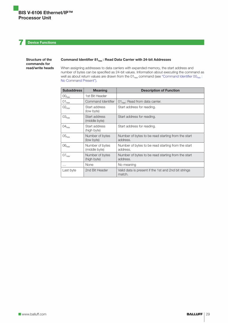
Command Identifier 81hex : Read Data Carrier with 24-bit Addresses
When assigning addresses to data carriers with expanded memory, the start address and
number of bytes can be specified as 24-bit values. Information about executing the command as
well as about return values are drawn from the 01hex command (see “Command Identifier 00hex :
No Command Present”).
Subaddress Meaning Description of Function
00hex 1st Bit Header
01hex Command Identifier 01hex: Read from data carrier.
02hex Start address
(low byte)
Start address for reading.
03hex Start address
(middle byte)
Start address for reading.
04hex Start address
(high byte)
Start address for reading.
05hex Number of bytes
(low byte)
Number of bytes to be read starting from the start
address.
06hex Number of bytes
(middle byte)
Number of bytes to be read starting from the start
address.
07hex Number of bytes
(high byte)
Number of bytes to be read starting from the start
address.
… None No meaning
Last byte 2nd Bit Header Valid data is present if the 1st and 2nd bit strings
match.
Structure of the
commands for
read/write heads
7 Device Functions

BIS V-6106 Ethernet/IP™
Processor Unit
30
Command Identifier 02hex : Write to Data Carrier
Writes USER data at the specified start address. The data length is equal to the number of bytes.
When using a data carrier with expanded memory, the Write to Data Carrier command can also
be executed as a command with 24-bit addresses.
Refer to: Command Identifier 81hex, Read Data Carrier with 24-bit Addresses.
Note
A password is required to write to read-only data carriers.
Write commands that are attempted with an invalid password will be acknowledged
with the status message Password Required or Password Invalid (see “Status codes”
on page 27).
Details about access passwords can be found in the manual of the UHF read/write
head used.
Subaddress Meaning Description of Function
00hex 1st Bit Header
01hex Command Identifier 02hex: Write to data carrier.
02hex Start address
(low byte)
Start address to be written from.
03hex Start address
(high byte)
Start address to be written from.
04hex Number of bytes
(low byte)
Number of bytes to be written starting from the start
address.
05hex Number of bytes
(high byte)
Number of bytes to be written starting from the start
address.
… None No meaning
Last byte 2nd Bit Header If the 1st and 2nd bit headers match, the data is valid.
Data is accepted from the processor unit only after the command has been accepted by the
processor unit and acknowledged.
Subaddress Meaning Description of Function
00hex 1st Bit Header
01hex Data Transmission of the data that is to be written to the data
carrier.
… Data Transmission of the data that is to be written to the data
carrier.
… None No meaning
Last byte 2nd Bit Header If the 1st and 2nd bit headers match, the data is valid
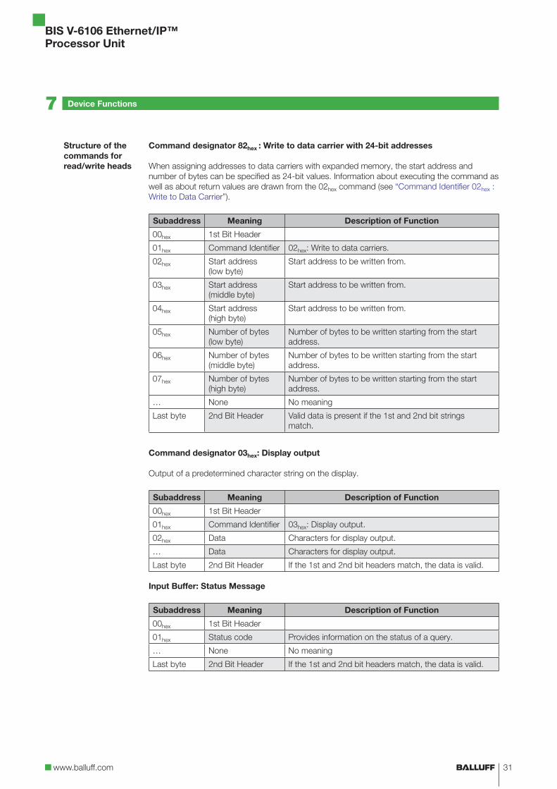
Input Buffer: Status Message
Subaddress Meaning Description of Function
00hex 1st Bit Header
01hex Data Provides information on the status of a query.
… Data No meaning
Last byte 2nd Bit Header If the 1st and 2nd bit headers match, the data is valid.
Structure of the
commands for
read/write heads
7 Device Functions
www.balluff.com
BIS V-6106 Ethernet/IP™
Processor Unit
31
Command designator 82hex : Write to data carrier with 24-bit addresses
When assigning addresses to data carriers with expanded memory, the start address and
number of bytes can be specified as 24-bit values. Information about executing the command as
well as about return values are drawn from the 02hex command (see “Command Identifier 02hex :
Write to Data Carrier”).
Subaddress Meaning Description of Function
00hex 1st Bit Header
01hex Command Identifier 02hex: Write to data carriers.
02hex Start address
(low byte)
Start address to be written from.
03hex Start address
(middle byte)
Start address to be written from.
04hex Start address
(high byte)
Start address to be written from.
05hex Number of bytes
(low byte)
Number of bytes to be written starting from the start
address.
06hex Number of bytes
(middle byte)
Number of bytes to be written starting from the start
address.
07hex Number of bytes
(high byte)
Number of bytes to be written starting from the start
address.
… None No meaning
Last byte 2nd Bit Header Valid data is present if the 1st and 2nd bit strings
match.
Command designator 03hex: Display output
Output of a predetermined character string on the display.
Subaddress Meaning Description of Function
00hex 1st Bit Header
01hex Command Identifier 03hex: Display output.
02hex Data Characters for display output.
… Data Characters for display output.
Last byte 2nd Bit Header If the 1st and 2nd bit headers match, the data is valid.
Input Buffer: Status Message
Subaddress Meaning Description of Function
00hex 1st Bit Header
01hex Status code Provides information on the status of a query.
… None No meaning
Last byte 2nd Bit Header If the 1st and 2nd bit headers match, the data is valid.
Structure of the
commands for
read/write heads
7 Device Functions

BIS V-6106 Ethernet/IP™
Processor Unit
32
Command designator 07hex: Store the start address for the "Auto Read" function
Configuring the start address after the data is read with the Auto Read function. For more details,
see the “Description of individual parameters” chapter on page 17.
Subaddress Meaning Description of Function
00hex 1st Bit Header
01hex Command Identifier 07hex: Save the start address for the Auto Read function.
02hex Start address
(low byte)
Address for the "Auto Read" function starting from which
the data carrier is read. The value is stored in the
EEPROM.
03hex Start address
(high byte)
Address for the "Auto Read" function starting from which
the data carrier is read. The value is stored in the
EEPROM.
… None No meaning
Last byte 2nd Bit Header If the 1st and 2nd bit headers match, the data is valid.
Input Buffer: Status Message
Subaddress Meaning Description of Function
00hex 1st Bit Header
01hex Status code Provides information on the status of a query.
… None No meaning
Last byte 2nd Bit Header If the 1st and 2nd bit headers match, the data is valid.
Command Identifier 87hex : Save the Start Address for the Auto Read Function with
24-bit addresses
When assigning addresses to data carriers with expanded memory, the start address and
number of bytes can be specified as 24-bit values. Information about executing the command as
well as about return values are drawn from the 07hex command (see “Command designator
07hex: Store the start address for the „Auto Read“ function”).
Subaddress Meaning Description of Function
00hex 1st Bit Header
01hex Command Identifier 07hex: Save the start address for the Auto Read function.
02hex Start address (low
byte)
Address for the "Auto Read" function starting from which
the data carrier is read. The value is stored in the
EEPROM.
03hex Start address
(middle byte)
Address for the "Auto Read" function starting from which
the data carrier is read. The value is stored in the
EEPROM (optional, 24-bit command).
04hex Start address (high
byte)
Address for the "Auto Read" function starting from which
the data carrier is read. The value is stored in the
EEPROM.
… None No meaning
Last byte 2nd Bit Header Valid data is present if the 1st and 2nd bit strings
match.
Structure of the
commands for
read/write heads
Structure of the
commands for
read/write heads
7 Device Functions

www.balluff.com
BIS V-6106 Ethernet/IP™
Processor Unit
33
Command designator 09hex: Type and serial number
If a data carrier is recognized in the active read/write zone of the read/write head, this command
will return the read-write head type as well as the data carrier type and serial number of the
detected data carrier.
Note
For details about read/write head types and data carrier types, see the “Description of
individual parameters” chapter on page 17.
Subaddress Meaning Description of Function
00hex 1st Bit Header
01hex Command Identifier 09hex: Read out type and serial number.
… None No meaning
Last byte 2nd Bit Header If the 1st and 2nd bit headers match, the data is valid.
If execution is successful, the response is passed to the input buffer in the following format:
Subaddress Meaning Description of Function
00hex 1st Bit Header
01hex Length Length (number of bytes including length)
02hex Read/write head
type
C = 01/VL = 02/VM = 03/VU = 04
03hex Data Carrier Type Data Carrier Type
04hex Serial Number / UID UID data that was transmitted from the data carrier.
05hex Serial Number / UID UID data that was transmitted from the data carrier.
… None No meaning
Last byte 2nd Bit Header If the 1st and 2nd bit headers match, the data is valid.
Structure of the
commands for
read/write heads
7 Device Functions

BIS V-6106 Ethernet/IP™
Processor Unit
34
Command designator 11hex: Copy data between data carriers
Copy data from one data carrier to another. The specified number of bytes will be copied from
the source start address in the source data carrier to the target start address in the target data
carrier. Care must be taken to ensure that the memory areas of the source and target data
carriers are compatible.
Subaddress Meaning Description of Function
00hex 1st Bit Header
01hex Command Identifier 11hex: Copy data carrier.
02hex Source start
address (low byte)
Copy the start address of the source data carrier for the
function from which copying is to start.
03hex Source start
address (high byte)
Copy the start address of the source data carrier for the
function from which copying is to start.
04hex Target start address
(low byte)
Copy the start address of the target data carrier for the
function from which copying is to start.
05hex Target start address
(high byte)
Copy the start address of the target data carrier for the
function from which copying is to start.
06hex Number of bytes
(low byte)
Number of bytes to be copied starting from the source
start address.
07hex Number of bytes
(high byte)
Number of bytes to be copied starting from the source
start address.
08hex Target R/W head
number
Number of the read/write head that the target data
carrier is in front of.
… None No meaning
Last byte 2nd Bit Header If the 1st and 2nd bit headers match, the data is valid.
Input Buffer: Status Message
Subaddress Meaning Description of Function
00hex 1st Bit Header
01hex Status code Provides information on the status of a query.
… None No meaning
Last byte 2nd Bit Header If the 1st and 2nd bit headers match, the data is valid.
Structure of the
commands for
read/write heads
7 Device Functions

www.balluff.com
BIS V-6106 Ethernet/IP™
Processor Unit
35
Command Identifier 91hex : Copy Data Between Data Carriers with 24-bit Addresses
When assigning addresses to data carriers with expanded memory, the start address and
number of bytes can be specified as 24-bit values. Information about executing the command as
well as about return values are drawn from the 11hex command (see “Command designator
11hex: Copy data between data carriers”).
Subaddress Meaning Description of Function
00hex 1st Bit Header
01hex Command Identifier 11hex: Copy data.
02hex Source start
address (low byte)
Copy the start address of the source data carrier for the
function from which copying is to start.
03hex Source Start
Address
(Middle Byte)
Copy the start address of the source data carrier for the
function from which copying is to start.
04hex Source start
address (high byte)
Copy the start address of the source data carrier for the
function from which copying is to start.
05hex Target start address
(low byte)
Copy the start address of the target data carrier for the
function from which copying is to start.
06hex Target Start
Address
(Middle Byte)
Copy the start address of the target data carrier for the
function from which copying is to start.
07hex Target start address
(high byte)
Copy the start address of the target data carrier for the
function from which copying is to start.
08hex Number of bytes
(low byte)
Number of bytes to be copied starting from the source
start address.
09hex Number of bytes
(middle byte)
Number of bytes to be copied starting from the source
start address.
0Ahex Number of bytes
(high byte)
Number of bytes to be copied starting from the source
start address.
0Bhex Target R/W head
number
Number of the read/write head that the target data
carrier is in front of.
… None No meaning
Last byte 2nd Bit Header If the 1st and 2nd bit headers match, the data is valid.
Structure of the
commands for
read/write heads
7 Device Functions

BIS V-6106 Ethernet/IP™
Processor Unit
36
Command designator 12hex: Initialize CRC_16 data check
The memory area of the data carrier used is prepared for use with a CRC data check. It is
initialized by writing USER data with a checksum.
If the CRC data check is enabled in the processor unit, then read and write commands on a
memory area that is not initialized leads to a CRC error.
Note
CRC data checks reduce the usable storage area in the data carrier, but it increases
the integrity of the data (see the “Description of individual parameters” chapter on
page 17).
Subaddress Meaning Description of Function
00hex 1st Bit Header
01hex Command Identifier 12hex: Initialize data carrier.
02hex Start address
(low byte)
Start address from which the CRC_16 data check is to
be carried out.
03hex Start address
(high byte)
Start address from which the CRC_16 data check is to
be carried out.
04hex Number of bytes
(low byte)
Start address from which the CRC_16 data check is to
be carried out.
05hex Number of bytes
(high byte)
Start address from which the CRC_16 data check is to
be carried out.
… None No meaning
Last byte 2nd Bit Header If the 1st and 2nd bit headers match, the data is valid.
Data is accepted from the processor unit only after the command has been accepted by the
processor unit and acknowledged.
Subaddress Meaning Description of Function
00hex 1st Bit Header
01hex Data Transmission of the data that is to be written to the data
carrier.
… Data Transmission of the data that is to be written to the data
carrier.
… None No meaning
Last byte 2nd Bit Header If the 1st and 2nd bit headers match, the data is valid.
Input Buffer: Status Message
Subaddress Meaning Description of Function
00hex 1st Bit Header
01hex Status code Provides information on the status of a query.
… None No meaning
Last byte 2nd Bit Header If the 1st and 2nd bit headers match, the data is valid.
Structure of the
commands for
read/write heads
7 Device Functions

www.balluff.com
BIS V-6106 Ethernet/IP™
Processor Unit
37
Command Identifier 92hex : Initialize CRC_16 Data Check with 24-bit Addresses
When assigning addresses to data carriers with expanded memory, the start address and
number of bytes can be specified as 24-bit values. Information about executing the command as
well as about return values are drawn from the 12hex command (see “Command designator
12hex: Initialize CRC_16 data check”).
Subaddress Meaning Description of Function
00hex 1st Bit Header
01hex Command Identifier 12hex: Initialize data carrier.
02hex Start address
(low byte)
Start address from which the CRC_16 data check is to
be carried out.
03hex Start address
(middle byte)
Start address from which the CRC_16 data check is to
be carried out.
04hex Start address
(high byte)
Start address from which the CRC_16 data check is to
be carried out.
05hex Number of bytes
(low byte)
Start address from which the CRC_16 data check is to
be carried out.
06hex Number of bytes
(middle byte)
Start address from which the CRC_16 data check is to
be carried out.
07hex Number of bytes
(high byte)
Start address from which the CRC_16 data check is to
be carried out.
… None No meaning
Last byte 2nd Bit Header If the 1st and 2nd bit headers match, the data is valid.
Structure of the
commands for
read/write heads
7 Device Functions

BIS V-6106 Ethernet/IP™
Processor Unit
38
Command designator 32hex: Write constant value to data carrier
Writes a constant value to the memory area, which is indicated with a start address and number
of bytes.
Subaddress Meaning Description of Function
00hex 1st Bit Header
01hex Command Identifier 32hex: Write a constant value to the data carrier.
02hex Start address
(low byte)
Start address to be written from.
03hex Start address
(high byte)
Start address to be written from.
04hex Number of bytes
(low byte)
Number of bytes to be written starting from the start
address.
05hex Number of bytes
(high byte)
Number of bytes to be written starting from the start
address.
… None No meaning
Last byte 2nd Bit Header If the 1st and 2nd bit headers match, the data is valid.
Data is accepted from the processor unit only after the command has been accepted by the
processor unit and acknowledged.
Subaddress Meaning Description of Function
00hex 1st Bit Header
01hex Data Value that is to be written to the data carrier.
… None No meaning
Last byte 2nd Bit Header If the 1st and 2nd bit headers match, the data is valid.
Input Buffer: Status Message
Subaddress Meaning Description of Function
00hex 1st Bit Header
01hex Data Value that is to be written to the data carrier.
… None No meaning
Last byte 2nd Bit Header If the 1st and 2nd bit headers match, the data is valid.
Structure of the
commands for
read/write heads
7 Device Functions

www.balluff.com
BIS V-6106 Ethernet/IP™
Processor Unit
39
Command Identifier B2hex : Write Constant Value to Data Carrier with 24-bit Addresses
When assigning addresses to data carriers with expanded memory, the start address and
number of bytes can be specified as 24-bit values. Information about executing the command as
well as about return values are drawn from the 12hex command (see “Command designator
12hex: Initialize CRC_16 data check”).
Subaddress Meaning Description of Function
00hex 1st Bit Header
01hex Command Identifier 32hex: Write a constant value to the data carrier.
02hex Start address
(low byte)
Start address to be written from.
03hex Start address
(middle byte)
Start address to be written from.
04hex Start address
(high byte)
Start address to be written from.
05hex Number of bytes
(low byte)
Number of bytes to be written starting from the start
address.
06hex Number of bytes
(middle byte)
Number of bytes to be written starting from the start
address.
07hex Number of bytes
(high byte)
Number of bytes to be written starting from the start
address.
… None No meaning
Last byte 2nd Bit Header Valid data is present if the 1st and 2nd bit strings
match.
Structure of the
commands for
read/write heads
7 Device Functions

BIS V-6106 Ethernet/IP™
Processor Unit
40
Note
Details and more information about the available parameters as well as
BIS VU-specific commands can be found in the manual of the BIS VU read/write
head used (Available at www.balluff.com).
Command Identifier 40hex: Select (Select Data Carrier in Multi-tag Mode)
In the Multi-tag Mode, the Select command selects a single data carrier from within a data carrier
population. A data carrier that is located in the active read/write zone of the antenna is accessed
and selected directly based on its EPC or its TID and is then available for further processing.
Subaddress Meaning Description of Function
00hex 1st Bit Header
01hex Command Identifier 40hex: Select Tag (Selecting the data carrier).
02hex Type EPC/TID EPC = 0
TID = 1
03hex No. of bytes Number of bytes for the data carrier identifier (EPC or
TID) that is transmitted in subsequent cycles.
04hex Reserved Set to 0.
05hex Reserved Set to 0.
06hex Reserved Set to 0.
… None No meaning
Last byte 2nd Bit Header Valid data is present if the 1st and 2nd bit strings
match.
Data is accepted from the processor unit only after the command has been accepted by the
processor unit and acknowledged.
Subaddress Meaning Description of Function
00hex 1st Bit Header
01hex Data 1st byte of the data carrier identifier (EPC or TID)
… Data Other bytes of the data carrier identifier (EPC or TID)
… None No meaning
Last byte 2nd Bit Header Valid data is present if the 1st and 2nd bit strings
match.
Input Buffer: Status Message
Subaddress Meaning Description of Function
00hex 1st Bit Header
01hex Status code Provides information on the status of a query.
… None No meaning
Last byte 2nd Bit Header If the 1st and 2nd bit headers match, the data is valid.
Specific
commands for
BIS VU read/write
heads
7 Device Functions

www.balluff.com
BIS V-6106 Ethernet/IP™
Processor Unit
41
Command Identifier 41hex: Unselect (Undo a Data Carrier Selection)
The Unselect command undoes one data carrier selection that was carried out with the Select
command. If a selection is not active, the status will remain unchanged.
Subaddress Meaning Description of Function
00hex 1st Bit Header
01hex Command Identifier 41hex: Unselect (Undo the data carrier selection).
… None No meaning
Last byte 2nd Bit Header If the 1st and 2nd bit headers match, the data is valid.
Input Buffer: Status Message
Subaddress Meaning Description of Function
00hex 1st Bit Header
01hex Status code Provides information on the status of a query.
… None No meaning
Last byte 2nd Bit Header If the 1st and 2nd bit headers match, the data is valid.
Specific
commands for
BIS VU read/write
heads
7 Device Functions

BIS V-6106 Ethernet/IP™
Processor Unit
42
Command Identifier 42hex: Read from EPC
Reads the EPC memory area of a data carrier that was previously selected with the Select
command.
In Single-Tag mode, that is, if only one data carrier is located in front of the active read/write zone
antenna, then the Select command can be disregarded. The Read from EPC command will be
automatically executed on the data carrier that is located in front of the antenna.
Note
If the order is executed without the preceding Select when more than one data carrier
is located in front of the antenna, the command will be acknowledged with the
Multiple-Tags status code.
Subaddress Meaning Description of Function
00hex 1st Bit Header
01hex Command Identifier 42hex: Read from EPC.
… None No meaning
Last byte 2nd Bit Header Valid data is present if the 1st and 2nd bit strings
match.
If execution is successful, the response is passed to the input buffer in the following format:
Subaddress Meaning Description of Function
00hex 1st Bit Header
01hex No. of bytes Number of bytes in the read EPC.
02hex EPC Data Transmission of EPC data that was read from the data
carrier.
… EPC Data Transmission of EPC data that was read from the data
carrier.
… None No meaning
Last byte 2nd Bit Header Valid data is present if the 1st and 2nd bit strings
match.
or
Input Buffer: Status Message
Subaddress Meaning Description of Function
00hex 1st Bit Header
01hex Status code Provides information about the status of a query:
… None No meaning
Last byte 2nd Bit Header If the 1st and 2nd bit headers match, the data is valid.
Specific
commands for
BIS VU read/write
heads
7 Device Functions

www.balluff.com
BIS V-6106 Ethernet/IP™
Processor Unit
43
Command Identifier 43hex: Write to EPC
Writes to the EPC memory area of a data carrier that was previously selected with the Select
command.
In Single-Tag mode, that is, if only one data carrier is located in front of the active read/write zone
antenna, then the Select command can be disregarded. The Write to EPC command will be
automatically executed on the data carrier that is located in front of the antenna.
Note
If the order is executed without the preceding Select and more than one data carrier is
located in front of the antenna, the command will then be acknowledged with the
Multiple-Tags status code.
The EPC can have a length of 2...62 bytes; the number of bytes must be even.
Subaddress Meaning Description of Function
00hex 1st Bit Header
01hex Command Identifier 43hex: Write to EPC.
02hex No. of bytes Number of bytes for the EPC to be written.
… None No meaning
Last byte 2nd Bit Header If the 1st and 2nd bit headers match, the data is valid.
Data is accepted from the processor unit only after the command has been accepted by the
processor unit and acknowledged.
Subaddress Meaning Description of Function
00hex 1st Bit Header
01hex EPC Data Transmission of the EPC data that is to be written to the
data carrier.
02hex EPC Data Transmission of the EPC data that is to be written to the
data carrier.
… None No meaning
Last byte 2nd Bit Header If the 1st and 2nd bit headers match, the data is valid.
Input Buffer: Status Message
Subaddress Meaning Description of Function
00hex 1st Bit Header
01hex Status code Provides information on the status of a query.
… None No meaning
Last byte 2nd Bit Header If the 1st and 2nd bit headers match, the data is valid.
Specific
commands for
BIS VU read/write
heads
7 Device Functions
BIS V-6106 Ethernet/IP™
Processor Unit
44
7 Device Functions
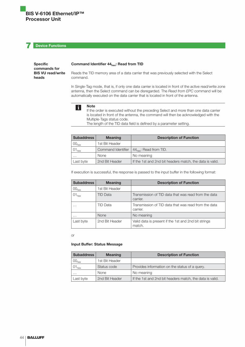
Command Identifier 44hex: Read from TID
Reads the TID memory area of a data carrier that was previously selected with the Select
command.
In Single-Tag mode, that is, if only one data carrier is located in front of the active read/write zone
antenna, then the Select command can be disregarded. The Read from EPC command will be
automatically executed on the data carrier that is located in front of the antenna.
Note
If the order is executed without the preceding Select and more than one data carrier
is located in front of the antenna, the command will then be acknowledged with the
Multiple-Tags status code.
The length of the TID data field is defined by a parameter setting.
Subaddress Meaning Description of Function
00hex 1st Bit Header
01hex Command Identifier 44hex: Read from TID.
… None No meaning
Last byte 2nd Bit Header If the 1st and 2nd bit headers match, the data is valid.
If execution is successful, the response is passed to the input buffer in the following format:
Subaddress Meaning Description of Function
00hex 1st Bit Header
01hex TID Data Transmission of TID data that was read from the data
carrier.
… TID Data Transmission of TID data that was read from the data
carrier.
… None No meaning
Last byte 2nd Bit Header Valid data is present if the 1st and 2nd bit strings
match.
or
Input Buffer: Status Message
Subaddress Meaning Description of Function
00hex 1st Bit Header
01hex Status code Provides information on the status of a query.
… None No meaning
Last byte 2nd Bit Header If the 1st and 2nd bit headers match, the data is valid.
Specific
commands for
BIS VU read/write
heads

www.balluff.com
BIS V-6106 Ethernet/IP™
Processor Unit
45
Command Identifier 45hex: Configure the Transmission Power
The transmission power for the antenna (ERP or EIRP), which is specified as a value in quarter
dBm increments, affects the maximum range of the read/write range of the antenna.
The maximum transmission power depends on the read/write head used.
Example:
Configuring a transmission power of 21 dBm (125 mW): 21 * 4 = 84 => (54hex)
Note
The entered value is not saved permanently and will be restored to the default value
when the Reader is rebooted.
Subaddress Meaning Description of Function
00hex 1st Bit Header
01hex Command Identifier 45hex: Set antenna power.
02hex Antenna power Antenna power (ERP/EIRP) in increments of
n * 0.25 dBm.
A value of 0 turns off the antenna.
Example:
An antenna power of 20 dBm corresponds to a value of
80hex
The entered value is not saved permanently and will be
reset to the default value when the Reader is rebooted.
… None No meaning
Last byte 2nd Bit Header Valid data is present if the 1st and 2nd bit strings
match.
Input Buffer: Status Message
Subaddress Meaning Description of Function
00hex 1st Bit Header
01hex Status code Provides information on the status of a query.
… None No meaning
Last byte 2nd Bit Header If the 1st and 2nd bit headers match, the data is valid.
Specific
commands for
BIS VU read/write
heads
7 Device Functions

BIS V-6106 Ethernet/IP™
Processor Unit
46
Command Identifier 46hex: Read out Transmission Power
Reads out the current transmission power (ERP). The transmission power is returned as a value
in the form of quarter dBm.
Example:
Reading out the transmission power returns the value of 54hex (= 84).
This corresponds to a transmission power of 21 dBm: 84/4 = 21
Subaddress Meaning Description of Function
00hex 1st Bit Header
01hex Command Identifier 46hex: Read out antenna power.
… None No meaning
Last byte 2nd Bit Header If the 1st and 2nd bit headers match, the data is valid.
If execution is successful, the response is passed to the input buffer in the following format:
Subaddress Meaning Description of Function
00hex 1st Bit Header
01hex Antenna power Antenna power in increments of n * 0.25 dBm or 0 for
disconnected antennae.
Example:
An antenna power of 20 dBm corresponds to a value of
80hex.
… None No meaning
Last byte 2nd Bit Header Valid data is present if the 1st and 2nd bit strings
match.
or
Input Buffer: Status Message
Subaddress Meaning Description of Function
00hex 1st Bit Header
01hex Status code Provides information on the status of a query.
… None No meaning
Last byte 2nd Bit Header If the 1st and 2nd bit headers match, the data is valid.
Specific
commands for
BIS VU read/write
heads
7 Device Functions

www.balluff.com
BIS V-6106 Ethernet/IP™
Processor Unit
47
Command Identifier 47hex: Read from Multiple Data Carriers
The Read from Multiple Data Carriers reads, depending on the configured type, the EPC or the
TID of all data carriers that are located in the active read/write area of the antenna.
Note
The length of the TID or EPC field parameters are configured on the BIS VU read/write
head.
Subaddress Meaning Description of Function
00hex 1st Bit Header
01hex Command Identifier 47hex: Read from multiple data carriers.
02hex Type EPC (0) or TID (1)
03hex Max. number of
data carriers
Maximum number of data carriers to be output 1…255,
(0 = no limit).
If the specification is greater than the maximum
specification of the connected heads, the lower value
applies.
04hex Data carrier
selection
All = 0 / Selected = 1
… None No meaning
Last byte 2nd Bit Header If the 1st and 2nd bit headers match, the data is valid.
If the EPCs transfer with the length of 12 bytes, the response in the input buffer is as follows:
Subaddress Meaning Description of Function
00hex 1st Bit Header
01hex No. of tags
02hex Number of bytes
per EPC
12
This corresponds to the length of the longest transmitted
EPC configured in the device. EPCs shorter than this
length are output right-justified and filled with zeros on
the left.
In the following, the (number of data carriers read) ×
(number of bytes per EPC) are transmitted.
For 64 bytes per EPC, the actual EPC length in ASCII is
specified in the 1st and 2nd byte of the EPC.
03hex EPC 1 EPC data uppermost address
… … …
… EPC 1 EPC data lowermost address
… EPC 2 EPC data uppermost address
… … …
EPC 2 EPC data lowermost address
… … …
… EPC n EPC data uppermost address
… … …
EPC n EPC data lowermost address
Last byte 2nd Bit Header If the 1st and 2nd bit headers match, the data is valid.
Specific
commands for
BIS VU read/write
heads
7 Device Functions

BIS V-6106 Ethernet/IP™
Processor Unit
48
Note
As circumstances require, the data must be transmitted over multiple BUS cycles.
Example of a received data frame with 2 EPCs and 12 bytes per EPC
(Illustration without bit headers).:
EPC 1: E2 FF 00 00 E2 11 90 22 E2 03 01 27
EPC 2: E2 00 90 51 32 05 01 74 07 80 C5 BE
If the EPCs transfer with the length of 64 bytes, the response in the input buffer is as follows:
Subaddress Meaning Description of Function
00hex 1st Bit Header
01hex No. of tags
02hex Number of bytes
per EPC
64
This corresponds to the length of the longest transmitted
EPC configured in the device. EPCs shorter than this
length are output right-justified and filled with zeros on
the left.
In the following, the (number of data carriers read) ×
(number of bytes per EPC) are transmitted.
For 64 bytes per EPC, the actual EPC length in ASCII is
specified in the 1st and 2nd byte of the EPC.
03hex EPC 1 Length MSB Length (ASCII)
04hex EPC 1 Length LSB Length (ASCII)
05hex EPC 1 EPC data uppermost address
… … …
… EPC 1 EPC data lowermost address
EPC 2 Length MSB Length (ASCII)
EPC 2 Length LSB Length (ASCII)
… EPC 2 EPC data uppermost address
… … …
EPC 2 EPC data lowermost address
EPC n Length MSB Length (ASCII)
EPC n Length LSB Length (ASCII)
… … …
… EPC n EPC data uppermost address
… … …
EPC n EPC data lowermost address
Last byte 2nd Bit Header If the 1st and 2nd bit headers match, the data is valid.
Note
As circumstances require, the data must be transmitted over multiple BUS cycles.
Specific
commands for
BIS VU read/write
heads
7 Device Functions

www.balluff.com
BIS V-6106 Ethernet/IP™
Processor Unit
49
Example of a received data frame with 2 EPCs and 64 bytes per EPC
(Illustration without bit headers):
EPC 1
Length: 48 bytes (34hex 38hex)
EPC: E2 FF 00 00 E2 11 90 22 E2 03 01 27 33 44 55 66
77 88 99 AC 01 02 03 04 05 06 07 08 09 0A 0B 0C
00 00 00 00 00 00 00 00 00 00 00 00 00 00 AA BB
EPC 2
Length: 12 bytes (31hex 32hex)
EPC: E2 00 90 51 32 05 01 74 07 80 C5 BE
Data:
Specific
commands for
BIS VU read/write
heads
7 Device Functions

BIS V-6106 Ethernet/IP™
Processor Unit
50
Command Identifier 48hex: Write Parameters
The Write Parameters command transfers parameters to the BIS VU read/write that affect its
behavior.
Subaddress Meaning Description of Function
00hex 1st Bit Header
01hex Command Identifier 48hex: Write parameters.
02hex Parameter
(Low Byte)
Parameter number
03hex Parameter
(High Byte)
Parameter number
04hex Length Length of the parameter in bytes
… None No meaning
Last byte 2nd Bit Header If the 1st and 2nd bit headers match, the data is valid.
Data is accepted from the processor unit only after the command has been accepted by the
processor unit and acknowledged.
Subaddress Meaning Description of Function
00hex 1st Bit Header
01hex Data Parameter data
… Data Parameter data
… None No meaning
Last byte 2nd Bit Header If the 1st and 2nd bit headers match, the data is valid.
Input Buffer: Status Message
Subaddress Meaning Description of Function
00hex 1st Bit Header
01hex Status code Provides information on the status of a query.
… None No meaning
Last byte 2nd Bit Header If the 1st and 2nd bit headers match, the data is valid.
Specific
commands for
BIS VU read/write
heads
7 Device Functions

www.balluff.com
BIS V-6106 Ethernet/IP™
Processor Unit
51
7 Device Functions
Command Identifier 49hex: Read Parameters
Reads out the parameter values that are currently set in the read/write head.
Subaddress Meaning Description of Function
00hex 1st Bit Header
01hex Command Identifier 49hex: Read parameters.
02hex Parameter
(Low Byte)
Parameter number
03hex Parameter
(High Byte)
Parameter number
… None No meaning
Last byte 2nd Bit Header If the 1st and 2nd bit headers match, the data is valid.
If execution is successful, the response is passed to the input buffer in the following format:
Subaddress Meaning Description of Function
00hex 1st Bit Header
01hex No. of bytes Number of bytes of the parameter that is transmitted in
the subsequent cycles.
02hex Data Parameter data
… Data Parameter data
… Data Parameter data
… Data Parameter data
Last byte 2nd Bit Header If the 1st and 2nd bit headers match, the data is valid.
or
Input Buffer: Status Message
Subaddress Meaning Description of Function
00hex 1st Bit Header
01hex Status code Provides information on the status of a query.
… None No meaning
Last byte 2nd Bit Header If the 1st and 2nd bit headers match, the data is valid.
Specific
commands for
BIS VU read/write
heads

BIS V-6106 Ethernet/IP™
Processor Unit
52
Command Identifier 50hex: Kill
The Kill command deactivates a data carrier previously selected with the Select command.
Note
Executing the Kill command permanently deactivates the selected data
carrier.
The deactivation cannot be undone.
Note
In order to execute the Kill command, a Kill password must first be set and written to
the data carrier.
Information about password protection and about locking and unlocking ("Lock")
of UHF RFID data carriers can be found in the UHF RFID standards EPCglobal™
Radio Frequency Identity Protocols Class-1 Generation-2 UHF RFID and
ISO IEC 18000-63.
The EPCglobal™ standard is available online at www.gs1.org/standards.
Subaddress Meaning Description of Function
00hex 1st Bit Header
01hex Command Identifier 50hex : Kill
02hex Password 1 1st byte password
03hex Password 2 2nd byte password
04hex Password 3 3rd byte password
Password 4
(High Byte)
4th byte password
… None No meaning
Last byte 2nd Bit Header If the 1st and 2nd bit headers match, the data is valid.
or
Input Buffer: Status Message
Subaddress Meaning Description of Function
00hex 1st Bit Header
01hex Status code Provides information on the status of a query.
… None No meaning
Last byte 2nd Bit Header If the 1st and 2nd bit headers match, the data is valid.
Specific
commands for
BIS VU read/write
heads
7 Device Functions

www.balluff.com
BIS V-6106 Ethernet/IP™
Processor Unit
53
Command Identifier 53hex: Bulk Read
The Bulk Read command reads the data from a data carrier population. Optionally from all of the
data carriers that are found in the active read/write zone of the antenna or from a subset that
was previously selected with the Select command.
The Bulk Read command first reports only the number of data carriers that were detected in the
active field of the antenna. The data in the data carriers is then read out and transmitted to the
controller.
If the data carriers are removed from the active field of the antenna in between the detection and
read out stages or if they cannot be successfully read out for other reasons, erroneous data may
occur. In which case, the data will be marked as invalid via a check byte at the end of the data
block and transmitted to the controller.
Data blocks marked as valid in their check bytes can be used without restrictions.
A maximum of 255 bytes from 255 data carriers can be read at a time.
Subaddress Meaning Description of Function
00hex 1st Bit Header
01hex Command Identifier 53hex : Bulk Read.
02hex Start address
(Low Byte)
Start address for reading.
03hex Start address
(High Byte)
Start address for reading.
04hex No. of bytes
(Low Byte)
Number of bytes to be read starting from the start
address.
05hex No. of bytes
(High Byte)
Number of bytes to be read starting from the start
address.
06hex Data carrier
selection
All = 0 / Selected = 1
07hex Max. Tags Maximum number of tags.
… None No meaning
Last byte 2nd Bit Header If the 1st and 2nd bit headers match, the data is valid.
Specific
commands for
BIS VU read/write
heads
7 Device Functions

BIS V-6106 Ethernet/IP™
Processor Unit
54
If execution is successful, the response is passed to the input buffer in the following format:
Subaddress Meaning Description of Function
00hex 1st Bit Header
01hex No. of tags Number of detected tags
02hex Number of Bytes
per Tag
Bytes to be transmitted per tag.
03hex Data 1 [0] Transmission of the 1st byte that was read from the 1st
data carrier.
… Data 1 [1] Transmission of the 2nd byte that was read from the 1st
data carrier.
… Data 1 […] Additional data from the 1st data carrier.
… Check Byte 1 A check byte is transmitted in the last byte from the first
data carrier, which indicates whether the data read is
valid:
00hex: Data valid
FFhex: Data invalid
… Data 2 [0] Transmission of the 1st byte that was read from the 2nd
data carrier.
… Data 2 [1] Transmission of the 2nd byte that was read from the 2nd
data carrier.
… Data 2 […] Additional data from the 2nd data carrier.
… Check Byte 2 A check byte is transmitted in the last byte from the
second data carrier, which indicates whether the data
read is valid:
00hex: Data valid
FFhex: Data invalid
… … …
… Data n [0] Transmission of the 1st byte that was read from the n-th
data carrier.
… Data n [1] Transmission of the 2nd byte that was read from the n-th
data carrier.
… Data n […] Additional data from the n-th data carrier.
… Check Byte n A check byte is transmitted in the last byte from the n-th
data carrier, which indicates whether the data read is
valid:
00hex: Data valid
FFhex: Data invalid
Last byte 2nd Bit Header If the 1st and 2nd bit headers match, the data is valid.
Specific
commands for
BIS VU read/write
heads
7 Device Functions
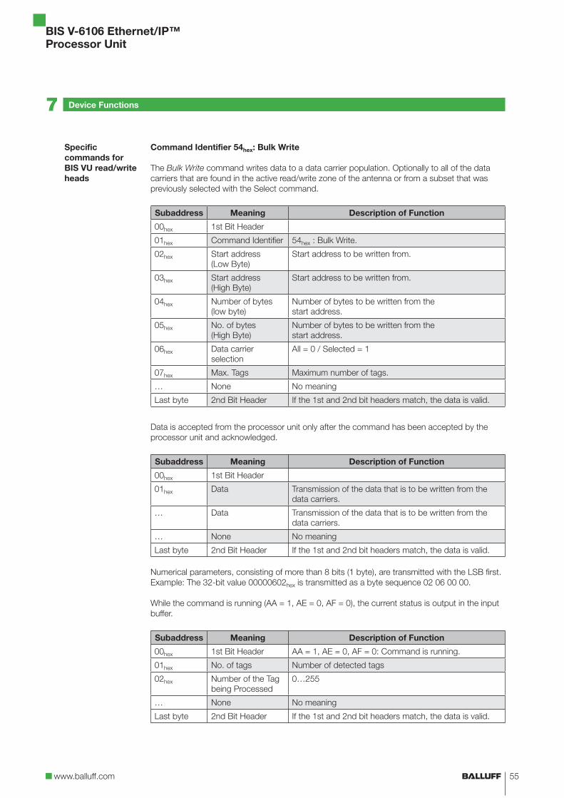
www.balluff.com
BIS V-6106 Ethernet/IP™
Processor Unit
55
Command Identifier 54hex: Bulk Write
The Bulk Write command writes data to a data carrier population. Optionally to all of the data
carriers that are found in the active read/write zone of the antenna or from a subset that was
previously selected with the Select command.
Subaddress Meaning Description of Function
00hex 1st Bit Header
01hex Command Identifier 54hex : Bulk Write.
02hex Start address
(Low Byte)
Start address to be written from.
03hex Start address
(High Byte)
Start address to be written from.
04hex Number of bytes
(low byte)
Number of bytes to be written from the
start address.
05hex No. of bytes
(High Byte)
Number of bytes to be written from the
start address.
06hex Data carrier
selection
All = 0 / Selected = 1
07hex Max. Tags Maximum number of tags.
… None No meaning
Last byte 2nd Bit Header If the 1st and 2nd bit headers match, the data is valid.
Data is accepted from the processor unit only after the command has been accepted by the
processor unit and acknowledged.
Subaddress Meaning Description of Function
00hex 1st Bit Header
01hex Data Transmission of the data that is to be written from the
data carriers.
… Data Transmission of the data that is to be written from the
data carriers.
… None No meaning
Last byte 2nd Bit Header If the 1st and 2nd bit headers match, the data is valid.
Numerical parameters, consisting of more than 8 bits (1 byte), are transmitted with the LSB first.
Example: The 32-bit value 00000602hex is transmitted as a byte sequence 02 06 00 00.
While the command is running (AA = 1, AE = 0, AF = 0), the current status is output in the input
buffer.
Subaddress Meaning Description of Function
00hex 1st Bit Header AA = 1, AE = 0, AF = 0: Command is running.
01hex No. of tags Number of detected tags
02hex Number of the Tag
being Processed
0…255
… None No meaning
Last byte 2nd Bit Header If the 1st and 2nd bit headers match, the data is valid.
Specific
commands for
BIS VU read/write
heads
7 Device Functions

BIS V-6106 Ethernet/IP™
Processor Unit
56
Upon successful execution (AE = 1, AF = 0), the number of written data carriers is transmitted
into the input buffer in the following format:
Subaddress Meaning Description of Function
00hex 1st Bit Header AE = 1, AF = 0: Command finished.
01hex No. of tags Number of detected tags.
02hex Number of
Successfully
Written Data
Carriers
0…255
… None No meaning
Last byte 2nd Bit Header If the 1st and 2nd bit headers match, the data is valid.
Numerical parameters, consisting of more than 8 bits (1 byte), are transmitted with the LSB first.
Example: The 32-bit value 00000602hex is transmitted as a byte sequence 02 06 00 00.
or
Input Buffer: Status Message
Subaddress Meaning Description of Function
00hex 1st Bit Header AF = 1: Status message
01hex Status code Provides information on the status of a query.
… None No meaning
Last byte 2nd Bit Header If the 1st and 2nd bit headers match, the data is valid.
Specific
commands for
BIS VU read/write
heads
7 Device Functions

www.balluff.com
BIS V-6106 Ethernet/IP™
Processor Unit
57
Command Identifier 55hex: Return Number of Tags
This command returns the number of data carriers that were found in the active read/write zone
of the antenna. Optionally, the total number of data carriers or the number of data carriers
selected with the Select command.
Subaddress Meaning Description of Function
00hex 1st Bit Header
01hex Command Identifier 55hex: Return Number of Tags.
02hex Data carrier
selection
All = 0 / Selected = 1
… None No meaning
Last byte 2nd Bit Header If the 1st and 2nd bit headers match, the data is valid.
If execution is successful, the response is passed to the input buffer in the following format:
Subaddress Meaning Description of Function
00hex 1st Bit Header
01hex Number of data
carriers read
0…255
… None No meaning
Last byte 2nd Bit Header If the 1st and 2nd bit headers match, the data is valid.
If no tag is identified, this command returns the number "0" and no error message.
or
Input Buffer: Status Message
Subaddress Meaning Description of Function
00hex 1st Bit Header
01hex Status code Provides information on the status of a query.
… None No meaning
Last byte 2nd Bit Header If the 1st and 2nd bit headers match, the data is valid.
Specific
commands for
BIS VU read/write
heads
7 Device Functions

BIS V-6106 Ethernet/IP™
Processor Unit
58
7 Device Functions
Command Identifier 56hex: Get RSSI (Receive Signal Strength Indicator)
This command returns the RSSI of a data carrier previously selected with the Select command.
The RSSI is a value which is proportional to the signal strength of the received response signal
from the data carrier.
Subaddress Meaning Description of Function
00hex 1st Bit Header
01hex Command Identifier 56hex: Get RSSI
02hex RSSI Type 0: Real-time RSSI
1: Pilot Tone RSSI
2: Data RSSI
… None No meaning
Last byte 2nd Bit Header If the 1st and 2nd bit headers match, the data is valid.
The RSSI value is returned in the form of an I component and a Q-component as a power level
measured in dBm.
Subaddress Meaning Description of Function
00hex 1st Bit Header
01hex I-value
02hex Q-value
… None No meaning
Last byte 2nd Bit Header If the 1st and 2nd bit headers match, the data is valid.
or
Input Buffer: Status Message
Subaddress Meaning Description of Function
00hex 1st Bit Header
01hex Status code Provides information on the status of a query.
… None No meaning
Last byte 2nd Bit Header If the 1st and 2nd bit headers match, the data is valid.
Specific
commands for
BIS VU read/write
heads

www.balluff.com
BIS V-6106 Ethernet/IP™
Processor Unit
59
57hex: Lock
The Lock command can block read or write access, as well as access of any kind, to memory
areas (RES, EPC, TID, USER) of a UHF data carrier. Depending on the level of security, the
memory areas can be password protected or completely blocked. The Mask and Action fields
specify which memory areas receive a new Lock Status and how these should appear. Using Bit
Masks allows the Lock Status of multiple memory areas to be changed at the same time.
Note
In order to successfully execute the Lock command, it is necessary to first provide the
correct Access Password for the data carrier via a Write Parameter command.
Passwords (Access and Kill) are stored in the Reserved memory area.
Mask: Bit Mask (16-Bit), used to determine which memory area of the selected data
carrier should be processed with respect to its Lock Status.
0: Memory area is not affected by the Action field
1: Memory area is affected by the Action field
Action: Bit Mask (16-Bit), used to determine how the Lock Status of the respective
memory areas should be changed.
The Lock Status can be set for individual memory areas by setting or resetting
the Lock and Permalock bits.
Bit No. 7 6 5 4 3 2 1 0
Memory
area
Access
PW
Access
PW
EPC EPC TID TID USER USER
Mask[0] Mask Mask Mask Mask Mask Mask Mask Mask
Action[0] Lock Perma-
lock
Lock Perma-
lock
Lock Perma-
lock
Lock Perma-
lock
Bit No. 15 14 13 12 11 10 9 8
Memory
area
Not used Kill PW Kill PW
Mask[1] Mask Mask
Action[1] Lock Perma-
lock
Lock Status of the EPC, TID and USER memory areas:
Lock Permalock Lock Status
0 0 Read and Write: No Password
0 1 Read and Write: No Password
(State can no longer be changed)
1 0 Read:
Write:
No Password
Access Password
1 1 Read:
Write:
No Password
Access Password
(State can no longer be changed)
Specific
commands for
BIS VU read/write
heads
7 Device Functions

BIS V-6106 Ethernet/IP™
Processor Unit
60
Note
The TID memory area is inherently read-only regardless of the Lock Status and can
only be read.
Lock Status of the Reserved memory area (Access Password and Kill Password)
Lock Permalock Lock Status
0 0 Read and Write: No Password
0 1 Read and Write: No Password
(State can no longer be changed)
1 0 Read and Write: Access Password
1 1 Read and Write: Not Possible
(State can no longer be changed)
Subaddress Meaning Description of Function
00hex 1st Bit Header
01hex Command Identifier 57hex: Lock.
02hex Mask[0]
03hex Mask[1]
04hex Action[0]
05hex Action[1]
… None No meaning
Last byte 2nd Bit Header If the 1st and 2nd bit headers match, the data is valid.
Input Buffer: Status Message
Subaddress Meaning Description of Function
00hex 1st Bit Header
01hex Status code Provides information on the status of a query.
… None No meaning
Last byte 2nd Bit Header If the 1st and 2nd bit headers match, the data is valid.
Specific
commands for
BIS VU read/write
heads
7 Device Functions

www.balluff.com
BIS V-6106 Ethernet/IP™
Processor Unit
61
Command Identifier 58hex: Activate Custom Parameters
Places the BIS V processor unit into the BIS M-41_ compatibility mode for use of custom
read/write commands in connection with BIS M - 1_ _ - 07 type data carriers.
Subaddress Meaning Description of Function
00hex 1st Bit Header
01hex Command Identifier 58hex: Set Custom Parameters
02hex Custom Parameter Read/Write with Custom Option
0: deactivated
1: activated
… None No meaning
Last byte 2nd Bit Header If the 1st and 2nd bit headers match, the data is valid.
or
Input Buffer: Status Message
Subaddress Meaning Description of Function
00hex 1st Bit Header
01hex Status code Provides information on the status of a query.
… None No meaning
Last byte 2nd Bit Header If the 1st and 2nd bit headers match, the data is valid.
Communication between the controlling system and processor unit is defined by a trace.
Communication between the host control system and the processor unit is implemented using a
control bit in the output and input buffers.
Basic sequence
1. The controller sends a command identifier to the processor unit in the output buffer with the
AV bit set.
The AV bit tells the processor unit that a job is starting and that the transmitted data is valid.
2. The processor unit accepts the job and confirms the job by setting the AA bit in the input
buffer.
3. If additional data needs to be exchanged for the job, readiness for additional data exchange
is indicated by inverting the TI and TO toggle bits.
4. The processor unit has correctly executed the job and sets the AE bit into the input buffer.
5. The controller has accepted all of the data. The AV bit in the output buffer is reset.
6. The processor unit resets all of the control bits set in the input buffer during the job
(AA bit, AE bit). The processor unit is ready for the next job.
Note
All specifications are typical values. Deviations are possible depending on the
application and combination of R/W head and data carrier.
The specifications apply to static operation; no CRC_16 data checking.
All specified read/write times are based on the communication between the data
carrier and the read/write head. The times for the data communication between the
processor unit and the host control system are not included.
BIS M-41_
compatibility
mode
Communication
Read/write times
7 Device Functions

BIS V-6106 Ethernet/IP™
Processor Unit
62
Mifare:
Read times Data carrier with 16 bytes per block
Data carrier detection ~ 20 ms
Read bytes 0 to 15 ~ 25 ms
For each additional 16-byte block started ~ 10 ms
Write times Data carrier with 16 bytes per block
Data carrier detection ~ 20 ms
Write bytes 0 to 15 ~ 60 ms
For each additional 16-byte block started ~ 30 ms
ISO 15693:
Read times Data carrier with 16 bytes per block
Data carrier detection ~ 20 ms
Read bytes 0 to 15 ~ 25 ms
For each additional 16-byte block started ~ 10 ms
Write times Data carrier with 16 bytes per block
FRAM
(BIS M-1_ _-02/20)
EEPROM
(BIS M-1_ _-03/07/08)
Data carrier detection ~ 20 ms ~ 20 ms
Write bytes 0 to 15 ~ 60 ms ~ 80 ms
For each additional 16-byte block started ~ 25 ms ~ 80 ms
High speed*:
Read times Data carrier with 64 bytes per block
Data carrier detection ~ 20 ms
Read bytes 0 to 63 ~ 14 ms
For each additional 64-byte block started ~ 6 ms
Write times Data carrier with 64 bytes per block
Data carrier detection ~ 20 ms
Write bytes 0 to 15 ~ 30 ms
For each additional 64-byte block started ~ 15 ms
*These times apply only for the combination of BIS VM-3_ _-401-S4 read/write head with
BIS M-1_ _-11/A, BIS M-1_ _-13/A, BIS M-1_ _-14/A, or BIS M-1_ _-15/A data carriers.
For read/write
heads BIS VM
7 Device Functions

www.balluff.com
BIS V-6106 Ethernet/IP™
Processor Unit
63
Read times:
Data carrier with 16 bytes per block BIS L-1_ _
Data carrier detection ~ 110 ms
Read bytes 0 to 15 ~ 175 ms
For each additional 16-byte block started ~ 40 ms
Data carrier BIS L-2_ _
Data carrier detection + Read data carrier ≤ 140 ms
Write times:
Data carrier with 16 bytes per block BIS L-1_ _
Data carrier detection ~ 110 ms
Write bytes 0 to 15 ~ 285 ms
For each additional 16-byte block started ~ 100 ms
Data carrier BIS L-2_ _
Writing not possible
Read times in static mode
Data carrier with 32 bytes per block
No. of bytes Read time [ms]
0 to 31 110
For each additional 32-byte block started 120
Data carrier with 64 bytes per block
No. of bytes Read time [ms]
0 to 63 220
For each additional 64-byte block started 230
Write times in static mode
Data carrier with 32 bytes per block
No. of bytes Read time [ms]
0 to 31 110 + n * 10
≥ 32 bytes y * 120 + n * 10
Data carrier with 64 bytes per block
No. of bytes Read time [ms]
0 to 63 220 + n * 10
≥ 64 bytes Y * 230 + n * 10
n = Number of contiguous bytes to write
y = Number of blocks to be processed
For read/write
heads BIS VL
For read/write
heads BIS C
7 Device Functions

BIS V-6106 Ethernet/IP™
Processor Unit
64
Example: 17 bytes should be written starting at address 187. Data carrier = 32 bytes per block.
Blocks 5 and 6 are processed, since the start address 187 is in block 5 and end address 203 is
in block 6.
t = 2 * 120 + 17 * 10 = 410
Read times within the first block in dynamic mode
Data carrier with 32 bytes per block
No. of bytes Read time [ms]
0 to 3 14
For each additional byte 3,5
0 to 31 112
Data carrier with 64 bytes per block
No. of bytes Read time [ms]
0 to 3 14
For each additional byte 3,5
0 to 63 224
m = Highest address to read
Formula: t = (m + 1) * 3.5 ms
Example: Read 11 bytes starting at address 9. This means that the largest address to be read is
19. This yields 70 ms.
Note
Dynamic operation with BIS C: The times indicated apply after the data carrier has
been detected. Otherwise 45 ms must be added for powering up until the data carrier
is recognized. To achieve the read times specified in dynamic operation, the Tag Type
parameter has to be set to "BIS C 32 Byte" or "BIS C 64 Byte" on the respective
head.
For read/write
heads BIS C
7 Device Functions
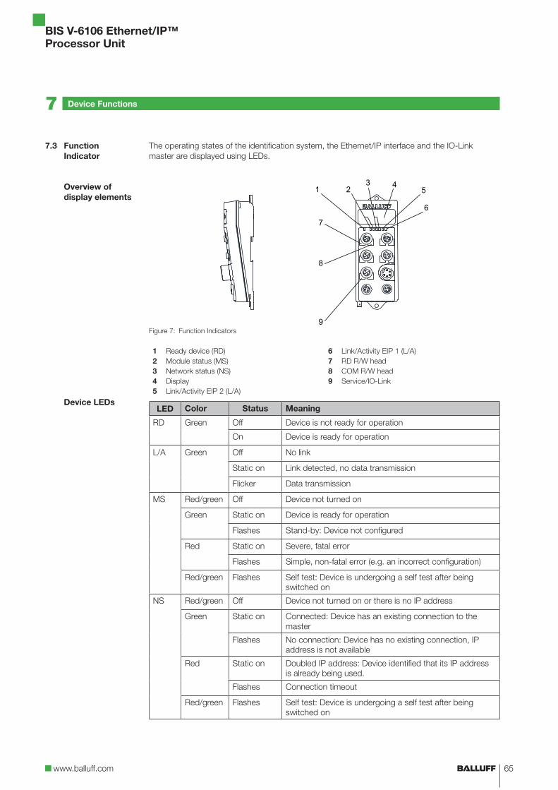
www.balluff.com
BIS V-6106 Ethernet/IP™
Processor Unit
65
The operating states of the identification system, the Ethernet/IP interface and the IO-Link
master are displayed using LEDs.
Figure 7: Function Indicators
1 Ready device (RD) 6 Link/Activity EIP 1 (L/A)
2 Module status (MS) 7 RD R/W head
3 Network status (NS) 8 COM R/W head
4 Display 9 Service/IO-Link
5 Link/Activity EIP 2 (L/A)
LED Color Status Meaning
RD Green Off Device is not ready for operation
On Device is ready for operation
L/A Green Off No link
Static on Link detected, no data transmission
Flicker Data transmission
MS Red/green Off Device not turned on
Green Static on Device is ready for operation
Flashes Stand-by: Device not configured
Red Static on Severe, fatal error
Flashes Simple, non-fatal error (e.g. an incorrect configuration)
Red/green Flashes Self test: Device is undergoing a self test after being
switched on
NS Red/green Off Device not turned on or there is no IP address
Green Static on Connected: Device has an existing connection to the
master
Flashes No connection: Device has no existing connection, IP
address is not available
Red Static on Doubled IP address: Device identified that its IP address
is already being used.
Flashes Connection timeout
Red/green Flashes Self test: Device is undergoing a self test after being
switched on
7.3 Function
Indicator
Overview of
display elements
Device LEDs
7 Device Functions

BIS V-6106 Ethernet/IP™
Processor Unit
66
Indicator
Function
RD R/W head
(Green)
COM R/W head
(Yellow)
Off Not ready No data carrier detected
LED lights up Ready for Operation Data carrier detected (CP)
LED flashes Cable break or R/W head not
connected
Data carrier is being processed
The IO port is assigned an LED for displaying the operational status.
Indi catorFunction
IO-Link Output Input
Off Ethernet/IP not yet
started
Signal = 0 Signal = 0
Yellow – Signal = 1 Signal = 1
Red Error Ioutput > Imax SC*
Green IO-Link communication
active
– –
Flashing
green
IO-Link node missing
or cable break
– –
* Short-circuit at PIN 1. In this case, the LED lights up in red.
R/W head LEDs
IO-Link port LED
7 Device Functions

www.balluff.com
BIS V-6106 Ethernet/IP™
Processor Unit
67
1. Reading 30 bytes at R/W head 1, start address 10
Once enough data has been read during the execution of the read job to fill the input buffer for
R/W Head 1, the data will be transmitted to the input buffer. The AE bit is not set until the
processor unit has finished the "Read" operation.
The "Job End" (AE bit) response is reliably set no later than before the last data has been sent.
This timing depends on the requested volume of data and the time response of the controller. In
the example, the use of italics for "Set AE Bit" calls your attention to this fact.
Control Identification System
1. Process output buffer
(note sequence):
2. Process Input Buffer
(note sequence):
01hex Command designator 01hex 00hex/0Fhex Set AA bit
02hex Start address 0Ahex 01…0Ehex Enter first 14 bytes
03hex Start address 00hex 00hex/0Fhex Invert TO bit
04hex No. of bytes 1Ehex 00hex/0Fhex Set AE bit
05hex No. of bytes 00hex
00hex/0Fhex Set AV Bit
3. Process input buffer: 4. Process input buffer:
01…0Ehex Copy first 14 bytes 01…0Ehex Enter second 14 bytes
Process output buffer: 00hex/0Fhex Invert TO bit
00hex/0Fhex Invert TI bit 00hex/0Fhex Set AE bit
5. Process input buffer: 6. Process input buffer:
01…0Ehex Copy second 14 bytes 01…02hex Enter last bytes
Process output buffer: 00hex/0Fhex Invert TO bit
00hex/0Fhex Invert TI bit 00hex/0Fhex Set AE bit
7. Process input buffer: 8. Process input buffer:
01…02hex Copy last bytes 00hex/0Fhex Reset AA and AE bits
Process output buffer:
00hex/0Fhex Reset AV bit
7.4 Examples
7 Device Functions

BIS V-6106 Ethernet/IP™
Processor Unit
68
2. Reading 30 bytes at R/W head 1, start address 10, problem during reading
Note
If a problem occurs, the AF bit is set with the corresponding status number instead of
the AE bit. Setting the AF bit cancels the job and declares it as finished.
Control Identification System
1. Process output buffer
(note sequence):
2. Process Input Buffer
(note sequence):
If problem occurs immediately!
01hex Command designator 01hex 00hex/0Fhex Set AA bit
02hex Start address 0Ahex 01hex Enter status number
03hex Start address 00hex 00hex/0Fhex Set AF bit
04hex No. of bytes 1Ehex
05hex No. of bytes 00hex
00hex/0Fhex Set AV Bit
3. Process input buffer: 4. Process input buffer:
01hex Copy status number 00hex/0Fhex Reset AA and AF bits
Process output buffer:
00hex/0Fhex Reset AV bit
Examples
7 Device Functions

www.balluff.com
BIS V-6106 Ethernet/IP™
Processor Unit
69
3. Reading 30 bytes at R/W head 1, start address 10, problem during reading
Note
If a problem occurs after transmission of the data has started, the AF bit is provided
instead of the AE bit together with a corresponding status number. The AF status
message is dominant. Which data is incorrect cannot be specified. Setting the AF bit
cancels the job and declares it as finished.
Control Identification System
1. Process output buffer
(note sequence):
2. Process Input Buffer
(note sequence):
01hex Command designator 01hex 00hex/0Fhex Set AA bit
02hex Start address 0Ahex 01…0Ehex Enter first 14 bytes
03hex Start address 00hex 00hex/0Fhex Invert TO bit
04hex No. of bytes 1Ehex
05hex No. of bytes 00hex
00hex/0Fhex Set AV Bit
3. Process input buffer: 4. Process input buffer:
If a problem has occurred!
01…0Ehex Copy first 14 bytes 01hex Enter status number
Process output buffer: 00hex/0Fhex Set AF bit
00hex/0Fhex Invert TI bit
5. Process input buffer: 6. Process input buffer:
01…0Ehex Copy status number 00hex/0Fhex Reset AA and AF bits
Process output buffer:
00hex/0Fhex Reset AV bit
Examples
7 Device Functions

BIS V-6106 Ethernet/IP™
Processor Unit
70
4. Writing 30 bytes at R/W head 1, start address 20
Control Identification System
1. Process output buffer
(note sequence):
2. Process Input Buffer
(note sequence):
01hex Command designator 02hex 00hex/0Fhex Set AA bit, invert TO bit
02hex Start address 14hex
03hex Start address 00hex
04hex No. of bytes 1Ehex
05hex No. of bytes 00hex
00hex/0Fhex Set AV Bit
3. Process output buffer: 4. Process output buffer:
01…0Ehex Enter first 14 bytes 01…0Ehex Copy first 14 bytes
00hex/0Fhex Invert TI bit Process input buffer:
00hex/0Fhex Invert TO bit
5. Process output buffer: 6. Process output buffer:
01…0Ehex Enter second 14 bytes 01…0Ehex Copy second 14 bytes
00hex/0Fhex Invert TI bit Process input buffer:
00hex/0Fhex Invert TO bit
7. Process output buffer: 8. Process output buffer:
01…02hex Enter last 2 bytes 01…02hex Copy last 2 bytes
00hex/0Fhex Invert TI bit Process input buffer:
00hex/0Fhex Set AE bit
9. Process output buffer: 10. Process input buffer:
00hex/0Fhex Reset AV bit 00hex/0Fhex Reset AA and AE bits
Examples
7 Device Functions

www.balluff.com
BIS V-6106 Ethernet/IP™
Processor Unit
71
5. Copying data from one data carrier to another
The data from one data carrier at a read/write head (source) is copied to a data carrier in front of
another read/write head (target). The data carriers have to be in front of the read/write heads
(even if dynamic mode has been configured) and must have the specified address range. The
command is processed in the buffer of the source head.
In the example, 17 bytes starting from address 10 of the data carrier are to be copied to the data
carrier in front of read/write head 3 starting from address 35.
Control Identification System
1. Process output buffer
(note sequence):
2. Process Input Buffer
(note sequence):
01hex Command designator 11hex 00hex/0Fhex Set AA bit, Set AE bit
02hex Source start address 0Ahex
03hex Source start address 00hex
04hex Target start address 23hex
05hex Target start address 00hex
06hex No. of bytes 11hex
07hex No. of bytes 00hex
08hex Target head number 03hex
00hex/0Fhex Set AV Bit
3. Process output buffer: 4. Process input buffer:
00hex/0Fhex Reset AV bit 00hex/0Fhex Reset AA and AE bits
Examples
7 Device Functions

BIS V-6106 Ethernet/IP™
Processor Unit
72
6. Writing to a data carrier with a constant value
A data carrier is to be written with 1000 bytes (constant value) starting from start address 80.
Control Identification System
1. Process output buffer
(note sequence):
2. Process Input Buffer
(note sequence):
01hex Command designator 32hex 00hex/0Fhex Set AA bit, invert TO bit
02hex Start address 50hex
03hex Start address 00hex
04hex Number of bytes E8hex
05hex No. of bytes 03hex
00hex/0Fhex Set AV Bit
3. Process output buffer: 4. Process output buffer:
01 Enter constant value 01 Copy constant value
00hex/0Fhex Invert TI bit Process input buffer:
00hex/0Fhex Set AE bit
5. Process output buffer: 6. Process input buffer:
00hex/0Fhex Reset AV bit 00hex/0Fhex Reset AA and AE bits
Examples
7 Device Functions

www.balluff.com
BIS V-6106 Ethernet/IP™
Processor Unit
73
7. Initializing a data carrier for CRC
The sequence for CRC initialization is similar to a write command. The start address and the
number of bytes must correspond to the maximum amount of data used.
In the example the complete memory area of a data carrier (752 bytes) is used. 658 bytes on the
data carrier are available as data bytes, since 94 bytes are required for the CRC.
Control Identification System
1. Process output buffer
(note sequence):
2. Process Input Buffer
(note sequence):
01hex Command designator 12hex 00hex/0Fhex Set AA bit, invert TO bit
02hex Start address 00hex
03hex Start address 00hex
04hex No. of bytes 92hex
05hex No. of bytes 02hex
00hex/0Fhex Set AV Bit
3. Process output buffer: 4. Process output buffer:
01…0Ehex Enter first 14 bytes 01…0Ehex Copy first 14 bytes
00hex/0Fhex Invert TI bit Process input buffer:
00hex/0Fhex Invert TO bit
5. Process output buffer: 6. Process output buffer:
01…0Ehex Enter second 14 bytes 01…0Ehex Copy second 14 bytes
00hex/0Fhex Invert TI bit Process input buffer:
00hex/0Fhex Invert TO bit
95. Process output buffer: 96. Process output buffer:
01…08hex Enter last bytes 01…08hex Copy last bytes
00hex/0Fhex Invert TI bit Process input buffer:
00hex/0Fhex Set AE bit
97. Process output buffer: 98. Process input buffer:
00hex/0Fhex Reset AV bit 00hex/0Fhex Reset AA and AE bits
Examples
7 Device Functions

BIS V-6106 Ethernet/IP™
Processor Unit
74
8. Creating a basic state for a R/W head or switching off a R/W head
The read/write heads for the identification system can be put into a basic state independently of
each other and the respective read/write head can be shut off.
Control Identification System
1. Process output buffer: 2. Go to the default state.
Process input buffer:
00hex/0Fhex Set GR bit 00hex/0Fhex Reset BB bit
R/W head is shut off
3. Process output buffer: 4. Process input buffer:
00hex/0Fhex Reset GR bit 00hex/0Fhex Set BB bit
R/W head is switched on
9. Switching off a read/write head antenna
During normal operation, all read/write head antennas are switched on. The antenna of a
respective R/W head can be switched off by setting the KA bit.
Control
1. Process output buffer:
00hex/0Fhex Set KA bit
The R/W head's antenna is switched back on by resetting the KA bit.
Examples
7 Device Functions

www.balluff.com
BIS V-6106 Ethernet/IP™
Processor Unit
75
10 Reading the EPCs of multiple data carriers in front of the antenna (only BIS VU)
With a maximum number of 5, EPC size of 12 bytes configured, 3 data carriers identified
Control Identification System
1. Process output buffer
(note sequence):
2. Process Input Buffer
(note sequence):
01hex Command designator 47hex 00hex/0Fhex Set AA bit
02hex Type EPC 00hex 01hex Number of data carriers 03hex
03hex Max. number 05hex 02hex Number of bytes per EPC 0Chex
00hex/0Fhex Set AV Bit 03hex…0Ehex First EPC 12 bytes
00hex/0Fhex Set AE bit
3a. Process input buffer: 4. Process input buffer:
01hex Note number of data
carriers
01…0Chex Enter second EPC 12 bytes
02hex Save number of bytes 0Dhex /0Ehex Enter third EPC 2 bytes
03hex /0Ehex Copy first EPC 12 bytes 00hex/0Fhex Invert TO bit
3b. Process output buffer:
00hex/0Fhex Invert TI bit
5a. Process input buffer: 6. Process input buffer:
01hex…0Chex Copy second EPC
12 bytes
01hex…0Ahex Enter third EPC 10 bytes
0Dhex /0Ehex Copy third EPC 2 bytes 00hex/0Fhex Invert TO bit
5b. Process output buffer:
00hex/0Fhex Invert TI bit
7a. Process input buffer: 8. Process input buffer:
01hex /0Ahex Copy third EPC 10 bytes 00hex/0Fhex Reset AA and AE bits
7b. Process output buffer:
00hex/0Fhex Reset AV bit
Examples
For configuration
with 16-byte
buffer size!
7 Device Functions

BIS V-6106 Ethernet/IP™
Processor Unit
76
11. Selecting a data carrier for further processing (only BIS VU)
For configuration with EPC size of 12 bytes
Control Identification System
1. Process output buffer
(note sequence):
2. Process Input Buffer
(note sequence):
01hex Command designator 40hex 00hex/0Fhex Set AA bit, Invert TO bit
02hex Type EPC 00hex
03hex Length of the EPC 0Chex
04hex Reserved 00hex
05hex Reserved 00hex
06hex Reserved 00hex
00hex/0Fhex Set AV Bit
3. Process output buffer: 4a. Process output buffer:
01hex…0Chex Enter 12 bytes EPC 01hex…0Chex Save EPC
00hex/0Fhex Invert TI bit 4b. Process input buffer:
00hex/0Fhex Set AE bit
5. Process output buffer: 6. Process input buffer:
00hex/0Fhex Reset AV bit 00hex/0Fhex Reset AA and AE bits
Examples
For configuration
with 16-byte
buffer size!
7 Device Functions

www.balluff.com
BIS V-6106 Ethernet/IP™
Processor Unit
77
12. Bulk Write (only BIS VU)
Write to all data carriers that are located in front of the antenna. Write 16 bytes starting at data
carrier address 3.
Control Identification System
1. Process output buffer
(note sequence):
2. Process Input Buffer
(note sequence):
01hex Command designator 54hex 00hex/0Fhex Set AA bit, invert TO bit
02hex Start address 03hex
03hex Start address 00hex
04hex No. of bytes 10hex
05hex No. of bytes 00hex
06hex Subset Type 00hex
07hex Max Tags FFhex
00hex/0Fhex Set AV Bit
3. Process output buffer: 4a. Process output buffer:
01…0Ehex Enter first 14 bytes 01…0Ehex Copy first 14 bytes
00hex/0Fhex Invert TI bit 4b. Process input buffer:
00hex/0Fhex Invert TO bit
5. Process output buffer: 6a. Process output buffer:
01…02hex Enter the last 2 bytes 01…02hex Copy last 2 bytes
00hex/0Fhex Invert TI bit 6b. Process input buffer:
01hex Enter the number of tags
found
02hex Enter the number of
successfully written tags
00hex/0Fhex Set AE bit
7. Process input buffer: 8. Process input buffer:
01hex Copy the number of tags
found
00hex/0Fhex Reset AA and AE bits
02hex Copy the number of
successfully written tags
Process output buffer:
00hex/0Fhex Reset AV bit
Examples
7 Device Functions

BIS V-6106 Ethernet/IP™
Processor Unit
78
13. Bulk Read (only BIS VU)
Read from all data carriers that are located in front of the antenna. Read 4 bytes starting at data
carrier address 3.
Control Identification System
1. Process output buffer
(note sequence):
2. Process Input Buffer
(note sequence):
01hex Command designator 53hex 00hex/0Fhex Set AA bit
02hex Start address 03hex 01hex Enter the number of tags
03hex Start address 00hex 02hex Enter the number of bytes
per tag04hex No. of bytes 04hex
05hex No. of bytes 00hex 03hex…0Ehex Enter 12 bytes of data and
the check byte06hex Subset Type 00hex
07hex Max Tags FFhex 00hex/0Fhex Invert TO bit
00hex/0Fhex Set AV Bit 00hex/0Fhex Set AE bit
3a. Process input buffer:
01hex Copy the number of tags
02hex Copy the number of bytes
per tag
03hex…06hex Copy the 4th byte of data
for the 1st tag
07hex Read the check byte
08hex…0bhex Copy the 4th byte of data
for the 2nd tag
0Chex Read the check byte
0Dhex /0Ehex Copy the 2nd byte of data
for the 3rd tag
3b. Process output buffer: 4. Process input buffer:
00hex/0Fhex Invert TI bit 01hex…08hex Enter l8 bytes of data and
the check byte
00hex/0Fhex Invert TO bit
00hex/0Fhex Set AE bit
5a. Process input buffer: 6a. Process input buffer:
01hex…02hex Copy the 2nd byte of data
for the 3rd tag
00hex/0Fhex Reset AA and AE bits
03hex Read the check byte
04hex…07hex Copy the 4th byte of data
for the 4th tag
08hex Read the check byte
5b. Process output buffer:
00hex/0Fhex Reset AV bit
Examples
7 Device Functions
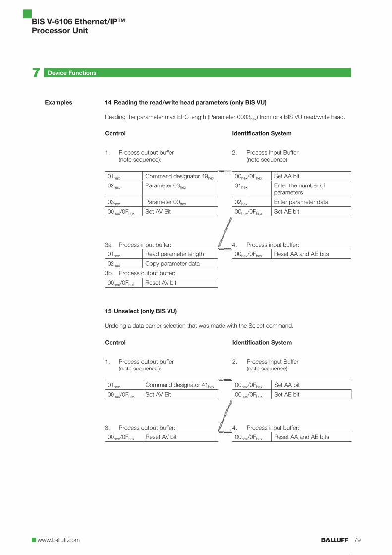
www.balluff.com
BIS V-6106 Ethernet/IP™
Processor Unit
79
14. Reading the read/write head parameters (only BIS VU)
Reading the parameter max EPC length (Parameter 0003hex) from one BIS VU read/write head.
Control Identification System
1. Process output buffer
(note sequence):
2. Process Input Buffer
(note sequence):
01hex Command designator 49hex 00hex/0Fhex Set AA bit
02hex Parameter 03hex 01hex Enter the number of
parameters
03hex Parameter 00hex 02hex Enter parameter data
00hex/0Fhex Set AV Bit 00hex/0Fhex Set AE bit
3a. Process input buffer: 4. Process input buffer:
01hex Read parameter length 00hex/0Fhex Reset AA and AE bits
02hex Copy parameter data
3b. Process output buffer:
00hex/0Fhex Reset AV bit
15. Unselect (only BIS VU)
Undoing a data carrier selection that was made with the Select command.
Control Identification System
1. Process output buffer
(note sequence):
2. Process Input Buffer
(note sequence):
01hex Command designator 41hex 00hex/0Fhex Set AA bit
00hex/0Fhex Set AV Bit 00hex/0Fhex Set AE bit
3. Process output buffer: 4. Process input buffer:
00hex/0Fhex Reset AV bit 00hex/0Fhex Reset AA and AE bits
Examples
7 Device Functions

BIS V-6106 Ethernet/IP™
Processor Unit
80
16. Setting the read/write head parameters (only BIS VU)
Setting an access password (Parameter 1002hex) for accessing a password-protected data
carrier.
Password: 12345678hex
Control Identification System
1. Process output buffer
(note sequence):
2. Process Input Buffer
(note sequence):
01hex Command designator 48hex 00hex/0Fhex Set AA bit, Invert TO bit
02hex Parameter 02hex
03hex Parameter 10hex
04hex Parameter Length 04hex
00hex/0Fhex Set AV Bit
3. Process output buffer: 4a. Process output buffer:
01hex Parameter Data 78hex 01…04hex Copy parameter data
02hex Parameter Data 56hex 4b. Process input buffer:
03hex Parameter Data 34hex 00hex/0Fhex Set AE bit
04hex Parameter Data 12hex
00hex/0Fhex Invert TI bit
5. Process output buffer: 6a. Process input buffer:
00hex/0Fhex Reset AV bit 00hex/0Fhex Reset AA and AE bits
Examples
7 Device Functions

www.balluff.com
BIS V-6106 Ethernet/IP™
Processor Unit
81
The display provides functions for starting up the BIS V. It can be used to set the IP and gateway
address and the subnet mask. In addition, tag data and version information can be output for
diagnostic purposes. It is controlled using a 2-button controller.
You can navigate within a menu level by holding the Enter/Down and Cancel/Up buttons for a
short time. You can switch between menu levels or confirm or cancel an action by pressing the
buttons longer.
Display
(Gray/black text,
blue backlighting)
Enter/Down button
Cancel/Up button
1
BALLUFFCancel or Enter
2
MainIP Set.InfoCancel (1 s)
Enter Cancel
4
InfoTag IDVersion
Enter (1 s)
3
MainIP Set.InfoCancel (1 s)
Enter
(1 s)
Cancel
(1 s)
Cancel (1 s)
5
ID, Head 1E00801D7E5475D55
Cancel
6
ID, Head 2E00801D7E5475D55
Enter
Display of the ID of the data
carrier in front of read
head 1
Display of the ID of the data carrier
in front of read head 2
While selecting Head_IDs 1…4 (5, 6, etc.) (1 s) can be reversed back to 4 by using cancel.
7.5 Display
Displaying tag
data
7 Device Functions

BIS V-6106 Ethernet/IP™
Processor Unit
82
1
BALLUFFCancel or Enter
2
MainSetupInfoCancel (1 s)
Enter Cancel
4
InfoTag IDVersion
Enter (1 s)
3
MainSetupInfoCancel (1 s)
Enter Cancel
5
InfoTag IDVersion
Enter (1 s)
6
Vers. InfoFW: 1.00IOL: 010A
Cancel (1 s)
Two versions are displayed: the firmware version of the controller (here 1.00) and the version text
of the IO-Link firmware (010A).
Version display
7 Device Functions

www.balluff.com
BIS V-6106 Ethernet/IP™
Processor Unit
83
1
BALLUFFCancel or Enter
2
MainIP Set.InfoCancel (1 s)
Enter
(1 s)Cancel (1 s)
4
IP ConfigStaticDHCP
Enter (1 s)
3
IP SetupIP Conf.IP Addr.Cancel (1 s)
Press Enter/Down to select the desired configuration.
Pressing Cancel (1 s) cancels the configuration (back to 3).
Press Enter (1 s) to apply the selected value.
5
Save newConfig?
Enter (1 s)
6
Setupfinished?
Cancel (1 s)
Back to 3Cancel (1 s)
Cancel (1 s)Enter
(1 s)
Back to 4 7
DeviceResetsnow!
Configuring the
IP configuration
7 Device Functions

BIS V-6106 Ethernet/IP™
Processor Unit
84
1
Cancel or Enter
2
Cancel (1 s)
Enter
(1 s)Cancel (1 s)
3
Enter
(1 s)Cancel (1 s)
5Enter (1 s)
4
Cancel (1 s)
Enter
(1 s)Cancel (1 s)
6
You can switch through the positions (1st, 2nd, 3rd) by pressing Enter/Down.
The current position starts flashing.
Press Cancel/Up to increase the number at the currently selected position.
Press Enter (1 s) to confirm the configured IP octet and switch to the next IP
octet.
Press Enter (1 s) to confirm the configured IP address in the 4th octet.
7
Enter (1 s)
8
Cancel (1 s)
Back to 2
Cancel (1 s) Enter (1 s)
Back to 4 9
A device reset is carried out (after
restart: Back to 1)
Note
The display shows the currently set IP address. An active IP address is indicated by a
flashing network status LED. If a new IP address is set by the operator, the IP
configuration will be set to a static address.
BALLUFFMain
IP Set.Info
IP SetupIP Conf.IP Addr.
IP Addr.192.168
010.120
IP SetupIP Conf.IP Addr.
IP Addr.192
Setupfinished?
Save newIP. Addr.?
DeviceResetsnow!
Configuring the
IP address
7 Device Functions

www.balluff.com
BIS V-6106 Ethernet/IP™
Processor Unit
85
1 Cancel or
Enter
2Enter (1 s)
3
Cancel (1 s) Cancel (1 s)
Enter
(1 s)
Cancel
(1 s)
6Enter (1 s)
5Enter (1 s)
4
Cancel (1 s) Cancel (1 s)
Enter
(1 s)Cancel (1 s)
7
You can switch through the positions (1st, 2nd, 3rd) by pressing Enter/Down.
The current position starts flashing.
Press Cancel/Up to increase the number at the currently selected position.
Press Enter (1 s) to confirm the configured subnet mask octet and switch to
the next octet.
Press Enter (1 s) to confirm the configured subnet mask in the 4th octet.
8
Enter (1 s)
9
Cancel (1 s)
Back to 3
Cancel (1 s) Enter (1 s)
Back to 5 10
A device reset is carried out (after
restart: Back to 1)
Note
The display shows the currently set subnet mask. An active subnet mask is indicated
by a flashing network status LED. If a new subnet mask is set by the operator, the IP
configuration will be set to a static address.
BALLUFFMain
IP Set.Info
IP SetupIP Conf.IP Addr.
Subnet Mask255.255
255.000
IP SetupIP Addr.Su. Ma.
IP SetupIP Conf.IP Addr.
Sub. Mask255
Save newSetup?
Setupfinished?
DeviceResetsnow!
Configuring the
subnet mask
7 Device Functions

BIS V-6106 Ethernet/IP™
Processor Unit
86
7 Device Functions
1 Cancel or
Enter
2Enter (1 s)
3
Cancel (1 s) Cancel (1 s)
Enter
(1 s)
Cancel
(1 s)
4
Enter
(1 s)
Cancel
(1 s)
7Enter (1 s)
6Enter (1 s)
5
Cancel (1 s) Cancel (1 s)
Enter
(1 s)Cancel (1 s)
8
You can switch through the positions (1st, 2nd, 3rd) by pressing Enter/Down.
The current position starts flashing.
Press Cancel/Up to increase the number at the currently selected position.
Press Enter (1 s) to confirm the configured gateway address octet and switch
to the next octet of the gateway address.
Press Enter (1 s) to confirm the configured gateway address in the 4th octet.
9
Enter (1 s)
10
Cancel (1 s)
Back to 3
Cancel (1 s) Enter (1 s)
Back to 6 11
A device reset is carried out (after
restart: Back to 1)
Note
The display shows the currently set gateway address. An active gateway address is
indicated by a flashing network status LED. If a new gateway address is set by the
operator, the IP configuration will be set to a static address. The gateway address
consists of the IP address and associated subnet mask. The operator can only
change the octet at binary positions where a 0 was set in the subnet mask.
Configuring the
gateway address
BALLUFFMain
IP Conf.IP Set.
MainIP Set.Info
IP SetupIP Addr.Sub. M.
Gateway192.168
002.001
IP SetupSu. Ma.Gateway
IP SetupSu. Ma.Gateway
Gateway192
Save newGateway?
Setupfinished?
DeviceResetsnow!

www.balluff.com
BIS V-6106 Ethernet/IP™
Processor Unit
87
7 Device Functions
The BIS V Ethernet/IP device includes an integrated webserver for retrieving detailed information
on the current status. Additionally, this can be used for the configuration of the IP settings and
for setting parameters for IO-Link.
For connection setup with the webserver, enter the IP address of the module in the address line
of the browser. Please use Internet Explorer 7 or higher.
Information on the configuration and network activity of the module can be found on this page.
The navigation bar appears in the upper area of the window, which allows you to switch between
the various web pages. A click on the corresponding text is all it takes.
7.6 Webserver
Home

BIS V-6106 Ethernet/IP™
Processor Unit
88
7 Device Functions
Information on the current process data and the port status of the device is visualized by LEDs
on this page.
If an RFID R/W head or an IO-Link-device is connected to the respective ports, then additional
information on the connected module will be displayed alongside the status information. Clicking
on this text or the device port acts as a link that takes you to "Device Properties".
Operation
Process

www.balluff.com
BIS V-6106 Ethernet/IP™
Processor Unit
89
7 Device Functions
The parameter settings of the selected module (R/W heads, IO-Link) are shown on this page.
Every module can be selected individually (right side).
IO-Link modules can also be configured using this page.
Note
The connected IO-Link module can be configured in this window.
A suitable controller with the corresponding software is needed to configure the
Ethernet IP device and the R/W ports, however.
Device Properties

BIS V-6106 Ethernet/IP™
Processor Unit
90
7 Device Functions
This page shows the current status of the module and the network, as it appears on the module.Diagnostic
Module

www.balluff.com
BIS V-6106 Ethernet/IP™
Processor Unit
91
7 Device Functions
The module description and module position and the IP address can be edited on this page. The
device settings can also be reset.
This function can only be used after entering a username and password:
Username: Balluff
Password: BISVEIP
Note
Restarting the device is necessary to refresh the IP settings.
Configurations

BIS V-6106 Ethernet/IP™
Processor Unit
92
7 Device Functions
Contact information is shown on this pageContact

www.balluff.com
BIS V-6106 Ethernet/IP™
Processor Unit
93
BIS V – 6 1 06 – 034 – C002
Balluff Identification System
Series V (V = variable)
System component
6 = Processor Unit
Generation (design/material)
1 = Generation 1, 2011 housing design, metal
Interface
02 = Profibus DP06 = Ethernet/IP08 = PROFINET10 = EtherCAT11 = CC-Link
Software type
034 = Ethernet/IP
Connection system
C002 = Power supply:5-pin flanged male connector with 7/8" external thread
IO-Link Master and USB: Flanged female connector M12 internal thread, 5-pin,
A-coded
Ethernet/IP 1: Flanged female connector M12 external thread, 4-pin, D-coded
EtherNet/IP 2: Flanged female connector M12 internal thread, 4-pin, D-coded
4 heads VL/VM/VU and future systems: Flanged female connector M12 internal thread,
5-pin, A-codedC102 = Such as C002, also supports BIS C read/write heads with an adapter cableC_04 = Such as C_02, power supply: 4-pin flanged male connector with 7/8" external thread
Note
More accessories for the BIS V-6106- _ _ can be found in the Balluff BIS catalog and
at www.balluff.com.
Type Code
Accessories
(Optional, not
included with
delivery)
Appendix

BIS V-6106 Ethernet/IP™
Processor Unit
94
Decimal Hex Control
Code
ASCII Decimal Hex ASCII Decimal Hex ASCII
0 00 Ctrl @ NUL 43 2B + 86 56 V
1 01 Ctrl A SOH 44 2C , 87 57 W
2 02 Ctrl B STX 45 2D - 88 58 X
3 03 Ctrl C ETX 46 2E . 89 59 Y
4 04 Ctrl D EOT 47 2F / 90 5 A Z
5 05 Ctrl E ENQ 48 30 0 91 5B [
6 06 Ctrl F ACK 49 31 1 92 5C \
7 07 Ctrl G BEL 50 32 2 93 5D [
8 08 Ctrl H BS 51 33 3 94 5E ^
9 09 Ctrl I HT 52 34 4 95 5F _
10 0 A Ctrl J LF 53 35 5 96 60 `
11 0B Ctrl K VT 54 36 6 97 61 a
12 0C Ctrl L FF 55 37 7 98 62 b
13 0D Ctrl M CR 56 38 8 99 63 c
14 0E Ctrl N SO 57 39 9 100 64 d
15 0F Ctrl O SI 58 3 A : 101 65 e
16 10 Ctrl P DLE 59 3B ; 102 66 f
17 11 Ctrl Q DC1 60 3C < 103 67 g
18 12 Ctrl R DC2 61 3D = 104 68 h
19 13 Ctrl S DC3 62 3E > 105 69 i
20 14 Ctrl T DC4 63 3F ? 106 6 A j
21 15 Ctrl U NAK 64 40 @ 107 6B k
22 16 Ctrl V SYN 65 41 A 108 6C l
23 17 Ctrl W ETB 66 42 B 109 6D m
24 18 Ctrl X CAN 67 43 C 110 6E n
25 19 Ctrl Y EM 68 44 D 111 6F o
26 1 A Ctrl Z SUB 69 45 E 112 70 p
27 1B Ctrl [ ESC 70 46 F 113 71 q
28 1C Ctrl \ FS 71 47 G 114 72 r
29 1D Ctrl ] GS 72 48 H 115 73 s
30 1E Ctrl ^ RS 73 49 I 116 74 t
31 1F Ctrl _ US 74 4 A J 117 75 u
32 20 SP 75 4B K 118 76 v
33 21 ! 76 4C L 119 77 w
34 22 „ 77 4D M 120 78 x
35 23 # 78 4E N 121 79 y
36 24 $ 79 4F O 122 7 A z
37 25 % 80 50 P 123 7B {
38 26 & 81 51 Q 124 7C |
39 27 ‘ 82 52 R 125 7D }
40 28 ( 83 53 S 126 7E ~
41 29 ) 84 54 T 127 7F DEL
42 2 A * 85 55 U
ASCII Table
Appendix

www.balluff.com
BIS V-6106 Ethernet/IP™
Processor Unit
95
Index
A
Accessories 93
ASCII Table 94
Auto Read
Standard 20
C
Checksum 18
Communication
Basic sequence 61
Control bit
Code Present 26
Default state 25
Head error 26
Job 25, 61
Job End 26, 61
Job Error 26
Job Start 26, 61
Toggle Bit In 25, 61
Toggle Bit Out 26, 61
Control Function 8
CRC check 18, 19
D
Data Integrity 8
Dimensions 13
Display elements 65
Double Bit Header 8
E
Electrical Data 13
I
Input buffer
Bit Header 26
Intended Use 6
IP Address 15
AnyBus IPconfig 15
DHCP 15
M
Mechanical Data 13
O
Operating conditions 14
Operating Principle 7, 11, 24
Output buffer 25
Bit Header 25
P
Processor Unit
Communication 61
Display elements 65
Operating Principle 24
Output buffer 25
Product Description 7, 11
R
Read times 62
Read/write head
Generate default state 74
turn-off 74
S
Safety 6
Installation 6
Operation 6
Startup 6
T
Technical Data
Dimensions 13
Electrical Data 13
Mechanical Data 13
Operating conditions 14
Type Code 93
Type, serial number 20
W
Write times 62, 63

www.balluff.com
www.balluff.com No. 911292-7
26 E
N · 0
3.1
22178 · D
16; S
ub
ject
to c
hange.
Rep
laces K
15.
Balluff GmbH
Schurwaldstraße 9
73765 Neuhausen a.d.F.
Germany
Tel. +49 7158 173-0
Fax +49 7158 5010


![Tris(ethylenediammonium) bis[(2-aminoethyl)ammonium] bis ...journals.iucr.org/e/issues/2010/05/00/wm2326/wm2326.pdf · Tris(ethylenediammonium) bis[(2-amino-ethyl)ammonium] bis[bis(l](https://img.pdfslide.us/doc/110x75/5e49e7fe0e042522d772f14a/trisethylenediammonium-bis2-aminoethylammonium-bis-trisethylenediammonium.jpg)