Embed Size (px)
Citation preview
BASICS OF "GRIFFITH'S FRACTURE MECHANICS"
Kari Santaoja
ABSTRACT
Rakenteiden Mekaniikka, Vol . 25 No 3 1992 , ss . 3 - 23
This article studies the basics of fracture mechanics. The theory proposed by
Griffith is derived starting from the examination of the law of kinetic energy. A
condition for crack growth is formulated. This equation also contains the
influence of kinetic energy and continuum dissipation. The condition is expressed
in the rate form i.e. it describes the response of a continuum in the case of a
running crack. In the special case, the derived condition reduces to that
proposed by Griffith.
INTRODUCTION
The aim of the present investigation is to study the basics of "Griffith's fracture
mechanics" and to derive the above-mentioned theory. A keen reader is
recommended to study the work of Santaoja (1992).
Because the behaviour of solids under loads is investigated in this work, it is
convenient to define the term 'system' as a group of material points containing
the whole body under consideration. Furthermore, the concept of a subsystem is
defined as an arbitrary collection of adjacent material points. The volume of the
system is denoted by Vb, in which the superscript b refers to the well-defined
volume, i.e. to the volume of the body. On the other hand, the volume of the
subsystem is denoted by V being without any superscript, which shows the
arbitrariness of the subsystem.
In the subsequent study the investigation is restricted to problems involving small
3
displacements, deformations and rotations. Therefore, with sufficient accuracy the
values of the variables can be replaced by their counterparts in the initial
configuration. Thus, it is obtained: V -4 V0, Vb -4 vbO etc.
LAW OF KINETIC ENERGY
In the present chapter the theorem of stress means is derived. The final result is
the law of kinetic energy.
First the dot product of the stress tensor a and an arbitrary vector field g is
formed . Next the divergence of the previously obtained dot product is studied.
Thus, the scalar of interest has the following appearance
in open vbo (1)
Scalar (1) is defined in the system Vbo except for the singularity at the crack tip
Ct, because the stress tensor a is unbounded at Ct. The vector field g is
assumed to be continuously differentiable in open VbO. Santaoja (1992. app. B)
derives the following equality.
<V·h)·e + h:ve (2)
where h is a bounded second-order tensor and e is a bounded vector. By
replacing the second-order tensor h by the stress tensor a and the vector e by
the vector g Equation (2) leads to
- - -V · (a · g) = (V·o)·g + o : Vg in open vbo (3)
where the notation V g stands for the open product of the vectors V and g [see
e.g. Malvern (1969, pp. 36 and 590 - 591)].
The material derivative of the vector vis denoted by 'V.
The Cauchy's equation of motion {see e.g. Malvern [1969, Eq. (5 .3.4)]}
4
- -V · a + Po b Po iJ in open ybo (4)
allows Equation (3) to be casted into the form
in open ybo (5)
The integration is performed over the volume of the subsystem V0 on both sides
of Expression (5). This procedure gives
J [ Po ( v-b)· g + a: V g] dV (6) vo
According to Santaoja [1992, Eq. (A.13)] "the modified generalized Gauss's
theorem" for the unbounded generalized tensor 0 can be written as
J V * 0 dV = f n * 0 dS (7) vo so
By replacing the star product * by the dot product · and denoting 0 = a · g the
modified generalized Gauss's Theorem (7) gives the following equality
(8)
Substitution of Equality (8) into the left-hand side of Equation (6) gives
J [ Po ( v- b)· g + a: V g] dV (9)
vo
The theorem of stress means, Equation (9), was derived by Signorini (1933, p.
232).
An arbitrary vector field g in Equation (9) is replaced by a virtual displacement
vector ou. By changing the order of the terms in the obtained equation one can
write
5
J p0 v·ou dV = f n·( o ·ou) dS + J p0 b·ou dV- J o:V(ou) dV (lO) vo so vo vo
Result (10) can be found in Malvern (1969, p. 242). Virtual strain tensor & and
virtual rotation tensor oro associated with the infinitesimal virtual displacement
vector ou are [see e.g. Malvern (1969, pp. 132, 161 and 239]
1 - • - -oe = - [(ou)V + V(ou)]
2 and oro = ~[Cou)V- vcou)J
2 ( 11)
in open ybo
Subtraction of Equation (11b) from Equation (11a) gives the following relationship
v (ou) = Oe -oro in open ybo (12)
Substituting Equation (12) into the last integral on the right-hand side of Equation
(10) yields
J p0 v·oudV = f n·(o·ou)dS + J p0 b·oudV- J o:oedV (13) vo so vo vo
Because the virtual rotation tensor Oro is skew-symmetric [i.e. OroT =- Oro] and
the stress tensor o is symmetric, the following equality holds [see e.g. FIUgge
(1972, pp. 18 and 19)]
o:Oro = 0 in open ybo (14)
Result (14) has been exploited during the derivation of Equation (13)
The above investigation can be repeated by replacing virtual displacement vector
ou by the differential displacement vector du. Instead of Equation (13) the
following expression is found
J Po v · du dV = f n · ( o · du) dS + J Po b · du dV - J o: de dV (15) vo so vo vo
The integrand on the left-hand side of Expression (15) can be manipulated
6
formally as follows
HU ~~ · ~~ dt = [ ~~ · ~~ l dt
~ r du . du + du . du 1 dt 2 dt dt dt dt
~ ~ r du . du 1 dt 2 dt dt dt
in open vbo (16)
The term on the left- hand side of Equation (15) is the differential kinetic energy
dK which according to Equations (15) and (16) is defined by
dK := f p0 v · du dV = d f ip0u·udV (17) vo vo
The first two terms on the right-hand side of Equation (15) form the differential
external work dWex i.e.
dwex := f t · dudS + J Po b · du dV (18) so vo
where the definition, t: = n ·a {see e.g. Malvern (1969, Eq. (3.2.8)], of the stress
tensor a has been exploited.
The last term in Expression (15) is the differential internal work dWi defined by
dWi :=- J a:dedV vo
Based on Definitions (17) ... (19) Expression (15) can be written as follows
(19)
(20)
Performing the integration from the initial configuration to the current
configuration on the both sides of Equation (20) gives
7
(21)
Where t.K is the increase of the kinetic energy, wax is the work performed on the
subsystem by the external forces and wi is the work performed by the internal
forces in the subsystem. Equation (21) is the law of kinetic energy and it can be
expressed as follows : 'The work of all the forces (internal and external) that act
on a mechanical subsystem equals the increase of the kinetic energy of the
subsystem' (Langhaar 1962, pp. 10- 13).
CONDITION THAT THE CRACK MAY EXTEND
This chapter derives 'the condition that the crack may extend' proposed by
Griffith in 1920. The approach utilized here is different from to that applied by
Griffith. Therefore the reader is recommended to investigate Griffith's work
(1920).
a)
Figure l.
8
n
tb tsbo
/v ~.
~~ , csbO~
~.
usbO b)
(a) A 3--dimensional system with a crack and (b) a detailed
illustration of the fracture process zone.
Figure 1 shows a 3-dimensional system (body) with an arbitrary-shaped crack
in the initial configuration. The crack tip Ct forms a curve in the 3-dimensional
system. The total surface sbO of the system ybO is divided into two different parts: 1Sb0 on which the surface tractions t are prescribed and usbO on which the
displacements u are prescribed. In front of the crack tip there is a zone in which
the process to break the bonds holding atoms together is in progress. This zone
is called 'fracture process zone' and it is illustrated in Figure l(b).
Equation (15) is rewritten for the whole system, viz.
J t ·dudS + J t ·dudS + J Po b · du dV SbO csbO ybO
- J a: de dV ybO
(22)
where the definition, t: = n · a, of the stress tensor a has been exploited. In
Equation (22) a surface integral over csbo has been added in order to take into
account the influence of the fracture process zone.
Next the system is assumed to undergo a process which implies a differential
displacement vector du, a differential strain tensor de and a differential crack
growth dA. The following equalities can be written
du = du dt = u dt dt
and de i: dt (23)
Equalities (23) are substituted into Equation (22) and the obtained result is
integrated over an arbitrary time interval; ilt = tb- ta. Although the time interval
ilt is an arbitrary one, the crack growth is assumed to start at the moment ta.
This procedure gives
9
lb lb lb
J [ J Po v · u dV] dt J [ J t · u dS ] dt + J [ J t · u dS ] dt 1
8 VbO 18 sbo Ia csbo
(24) lb lb
+ J [ J Po b · u dV] dt - J [ J a: e dV] dt 18 vbo Ia vbo
The term to describe the influence of the fracture process zone, i.e. the second
term on the right-hand side of Equation (24), is studied in more detail. This term
is
lb
J [ J t · u dS] dt (25)
18
csbO
It is noteworthy that the investigation of the above term is not included in the
(classical) continuum mechanics, which makes the derivation complicated. This
is due to the fact that the study of the above mentioned term demands an
investigation of the events on the atomic lattice. This lies beyond the scope of
the (macroscopic) continuum mechanics.
The term inside the brackets of Term (25) is the rate of the crack separation
work denoted by ·c and defined by
c := J T·uds (26) csbo
Figure 2(a) gives an ideal atomic-level view of the fracture process. During the
crack growth two new surfaces are created in the material. The upper surface is
denoted by the superscript + whereas the superscript - stands for the lower
surface. The attractive forces (per unit area) in the atomic lattice are denoted by
T+ and T-. Figure 2(b) shows the 'surface' tractions T+ and T- as well as the
outward unit normals n+ and n- of the forming crack surfaces. The positive
integration path is shown by the small arrows in Figure 2(b) (see e.g. Apostol
1962, II, Sect. 5.2.7).
10
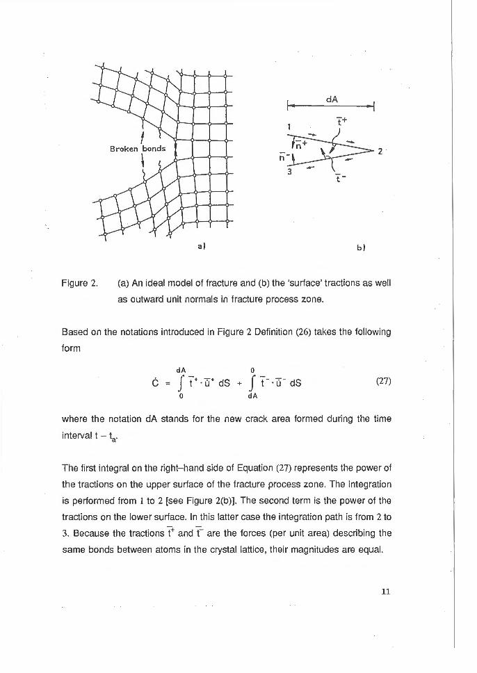
Figure 2.
, .. dA .. , t +
2 n
t: -
a) b)
(a) An ideal model of fracture and (b) the 'surface' tractions as well
as outward unit normals in fracture process zone.
Based on the notations introduced in Figure 2 Definition (26) takes the following
form
(27)
where the notation dA stands for the new crack area formed during the time
interval t - ta.
The first integral on the right-hand side of Equation (27) represents the power of
the tractions on the upper surface of the fracture process zone. The integration
is performed from 1 to 2 [see Figure 2(b)]. The second term is the power of the
tractions on the lower surface. In this latter case the integration path is from 2 to
3. Because the tractions T+ and T- are the forces (per unit area) describing the
same bonds between atoms in the crystal lattice, their magnitudes are equal.
11
With the change in the integration direction the integral changes its sign (see
Apostol 1957, Definition 9-5). In the light of the above Equation (27) yields
which leads to
dA J t" +. (u+- u- -) ds
0
(28)
(29)
According to Equations (25), (26) and (29) the crack separation work C carried
out during the investigated period ~t = tb - ta is found to be
tb dA
c = J [ J t"+ · cu-+- u- -) ds 1 dt t. 0
(30)
The crack separation work C depends on the following three variables: the crack
growth dA; the material and (if the material is not homogeneous) the location of
the crack tip. The above can be written as C = C[ A(xl' x2, x3)]. Therefore, the
rate of the crack separation work ·c can be written in the following form
C(A) = dC = ac dA = ac A dt iJA dt CJA
dC · - A dA
(31)
Because the crack separation work C depends only on the crack area A and on
the material under consideration, the partial derivative ac I oA equals the total
derivative dC 1 dA. This feature has been exploited in Equation (31). The problem
in formulation of derivatives with respect to the crack area A will be discussed in
the chapter headed 'Discussion and Conclusions'.
In a homogeneous material the derivative dC I dA is a (material dependent)
constant and it is traditionally denoted by
12
dC 2y :=-
dA (32)
In Equation (30) the 'surface' traction T+ is the force (per unit area) to overcome
the attractive forces in the atomic lattice and (u+ - ·u-) is the corresponding
velocity. The atom bond strength depends on the material. Also the velocity field
on the crack surfaces during the bond breakage may be characteristic of
different materials. Thus, most of the evidence supports a view that the crack
separation work C is a material parameter. According to Equation (30) the unit of
C is work. Therefore, based on Definition (32) 2y is called the rate of the crack
separation work. However, in the present case the word 'rate' does not refer to
the material derivative, but indicates a derivative with respect to the crack area
A.
The last term on the right-hand side of Equation (24) is
tb
-J [ J o: e dV 1 dt (33)
' · vbo
The strain rate tensor ·e is assumed to be separable into two different terms as
follows
· · e ·d e = e + e (34)
where .Ee is the elastic (reversible) strain rate tensor and ·Ed is the dissipative
(irreversible) strain rate tensor. It is noteworthy that the elastic strain rate tensor
· E8 also contains the effect of thermal expansion. The dissipative strain rate
tensor ·Ed can be used in the description of a viscoelastic, viscoplastic etc.
deformation. Separation (34) allows the term inside the brackets of Expression
(33) to be written in the following form
J o: i: dV = J o: e8 dV + J o: i:d dV (35) vbo vbo vbo
Strain-energy density denoted by w is defined by
13
w
The strain-energy W is
W := f w dV vbo
(36)
(37)
Based on Equations (36) and (37) the first term on the right- hand side of
Equation (35) is found to be
f a: e9 dV = f w dV = W (38) vbo vbo
In the system shown in Figure l(a) the value of the strain-energy density w
varies within the system i.e. w is a function of the coordinates (xl' 'S· x3) .
Furthermore, the crack area A has a certain influence on the magnitude of the
strain-energy density. Thus, it can be written
W(A) = J w(x1, x2, x3; A) dV vbo
where the crack area A is interpreted as a parameter.
Equations (36) and (39) give
dW(A)
dA
CJW(A)
a A
(39)
(40)
The first equality in Expression (40) shows the fact that the partial derivative of
W(A) equals the (total) derivative of W(A), because W(A) is a function of one
variable (see e.g. Piskunov 1974, I, p. 269). The second equality can be found in
Korn and Korn (1968, p. 103).
The second term on the right-hand side of Equation (35) is called the power of
continuum dissipation denoted by ·o and defined by
14
D(A) = J a: ed dV (41) vbo
Application of Definition (17) shows that the term inside the brackets on the left
hand side of Equation (24) is the material derivative of the kinetic energy "K (of
the whole system). It is
K(A) = J p0v·udV (42) vbo
Based on Equation (18) the rate of the external work ·wex (of the whole system)
is
· ex J: - - J W = J t · u dS + Po b · u dV (43) sbo vbo
Equations (26), (31), (35), (36), (41), (42) and (43) allow Expression (24) to be
casted into the form
tb
J [ K(A) - W 9 x(A) + C(A) + W(A) + D(A)] dt 0 (44)
Ia
Because the time interval Llt = tb - ta is an arbitrary interval, the integrand of
Integral (44) has to vanish at any moment, viz.
0 (45)
which can be written in the following form
( dK _ dWex + dC + dW + dO] A dA dA dA dA dA
0 (46)
In the case of a growing crack, i.e. when ·A ~ 0, the term inside the parentheses
has to vanish . This is
15
dK _ dWex + dC + dW + dD = 0 if A ::~= o (47) dA dA dA dA dA
The above equation is here called the condition for crack growth.
In the subsequent part of the present chapter deformation is assumed to be pure
elastic. This can be argued by the following remark given by Barenblatt.
The papers by G. R. lrwing (1947) and E. 0. Orowan (1950), in which the concept
of quasi- brittle fracture was developed, represent an important stage in the
theory of cracks. Irwin and Orowan noticed that a number of materials, which
behave as highly ductile in standard tensile tests, fracture by a quasi- brittle
mechanism when cracks are forming. This means that the arising plastic
deformations are concentrated in a very narrow layer near the surface of a crack.
As was shown by Irwin and Orowan, it is possible in such cases to employ
Griffith's theory of brittle fracture, introducing instead of surface tension the
effective density of surface energy. This quantity, in addition to the specific work
required to produce rupture of internal bonds (= surface tension), includes the
specific work required to produce plastic deformations in the surface layer of a
crack; it is sometimes several orders of magnitude larger than the surface
tension. (Barenblatt 1962, p. 65).
Based on the above the following is obtained
which yields that D - 0 (48)
Equation (43) gives
dW 9 x dA ---
dA dt (49)
which yields
16
T ·au ds ()A
- au p0 b· - dV
()A (50)
The first term on the right-hand side of Equation (50) exploits the following fact:
On the surface usbO on which the displacements u are prescribed (but can
change within time t) the displacements u are independent of the crack growth
(or crack area A) and therefore the partial derivative ()u I ()A vanishes on uSbO.
Hell an [ 1985, Eq. (3 .23)] gives the expression for the potential energy n, viz.
ll(A) = J w dV - J t · u dS - J Po b · u dV (51) vbo tsbo vbo
which gives
d n c A) = J a w d v _ J t . au dS dA vbo ()A tsbo ()A
(52)
Substitution of Equation (40) into Expression (52) yields
dll(A) = J a: aee dV- J t · au dS dA vbo ()A tsbo ()A
(53)
Equations (40), (48), (50) and (52) allow Equation (47) to be written in the
following form
dK(A)
dA +
dn(A)
dA + dC(A) = O
dA if A ;e o (54)
which is here called the condition for crack growth for pure elastic deformation.
Griffith (1920, p. 166) assumed that the strains E are elastic, which is assumed
also in Equation (54). Although he did not mention it explicitly, he also assumed -
that the deformation is quasi-static, i.e. K = 0, and that the body forces b can be
neglected. Based on the above discussion Condition (54) reduces into
17
dTI(A)
dA +
dC(A)
dA 0 <if A :t:- o) (55)
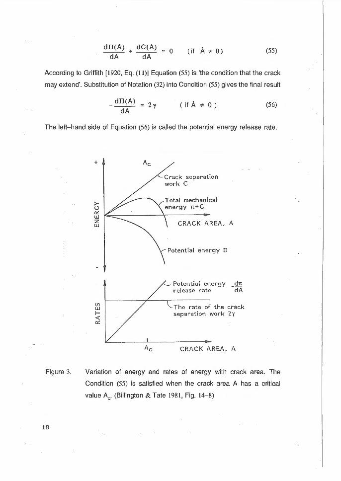
According to Griffith [1920, Eq. (11)] Equation (55) is 'the condition that the crack
may extend'. Substitution of Notation (32) into Condition (55) gives the final result
dTI(A) = 2y
dA < if A :t:- o ) (56)
The left- hand side of Equation (56) is called the potential energy release rate.
Figure 3.
18
+
>(..) ~ u.J z u.J
Crack separation work C
/'Total mechanical energy n+C
CRACK AREA, A
Potential energy II
'----- Potential energy dn t·elease rate - dA
\_The rate of the crack separation wot·k 2y
CRACK AREA, A
Variation of energy and rates of energy with crack area. The
Condition (55) is satisfied when the crack area A has a critical
value Ac. (Billington & Tate 1981, Fig. 14-8)
Figure 3 illustrates Condition (55) by showing that in case the crack area A
equals its critical value Ac the total mechanical work n + C has a stationary
value i.e. d(TI + C) 1 dA = 0.
DISCUSSION AND CONCLUSIONS
The focus of the present work was to investigate the basics of fracture
mechanics.
The mathematical derivation was begun by examining of the Cauchy's equation
of motion (the momentum principle). This led to the introduction of the theorem
of stress means. By utilizing the symmetry of the stress tensor (the moment of
momentum principle) the theorem of stress means provided the law of kinetic
energy. The condition for crack growth was derived by applying the above
mentioned law. This expression also includes the influence of kinetic energy as
well as that of the continuum dissipation on the crack growth process. If a pure
elastic deformation, a quasi-static process and the absence of body forces is
assumed the derived law reduces to that proposed by Griffith.
The author is willing to open the discussion about the physical interpretation of
the derivatives with respect to the crack area A (or crack length). As an
introduction to the investigation of this problem the following is expressed. There
are two different kinds of variables: Independent and dependent. The role of
these variables is clarified by Myskis (1975) as follows.
Usually it is possible to pick out certain variables from a number of interrelated
quantities such that the values of the variables can be taken arbitrarily whereas
the values of the other quantities are determined by the values of the variables
entering into the first group. The variables of the first type are called independent
variables (or arguments) and the variables of the second type are called
dependent variables (or functions). As an example let us consider the
19
relationship between the area S of a circle and the length R of its radius. It is
natural to regard R as an independent variable and choose its values arbitrarily;
then the area computed by the formula S = nR2 is a dependent variable in this
functional relation . It should be noted that when we have a functional relation
between variables the distinction between the independent variables and the
dependent ones is sometimes conditional. For instance, in the previous example
the area of the circle S would have been taken as an independent variable and
the radius R as the dependent variable. (Myskis 1975, pp. 39 and 40) (the last
sentence was written by the author but it is faithful the idea of the example given
by Myskis).
The above description given by Myskis can also be stated by using the law of
cause and effect: The independent variable is a cause and the dependent
variable is an effect.
The problem arises from the fact that from the physics point of view the
derivatives with respect to the crack area A are confusing. The following
discusses about this question.
The (partial) derivatives are formulated with respect to the independent variables.
When fracturing of continua is considered the loading is the cause and the crack
growth (the crack area) A (or the crack length a in the 2-dimensional case) is the
effect. Thus, from the physics' point of view loading is the cause and the crack
growth is the effect. Therefore the derivatives oloa and oloA are inconsistent
with the physics of a fracturing process. From the pure mathematics point of
view the roles of the dependent and independent variables can be exchanged,
as discussed by Myskis. But in real nature when fracturing of materials is
examined the exchange is difficult to imagine- at least a saw is needed.
A way out of the previous problem can be found: A new theory has to be
prepared. This theory should be formulated in a manner that excludes the crack
20
area A (or the crack length in the 2-dimensional case) from the list of
independent variables.
ACKNOWLEDGEMENTS
The author is willing to thank associate Professor Eero-Matti Salonen, Helsinki
University of Technology, for helpful discussions. This work is a part of the
'Advanced Structural Analysis' programme carried out at the Technical Research
Centre of Finland (VTI). The financial support from Valmet Corporation, ADCO
Advanced Composites Oy and NESTE Chemicals and TEKES (the Technology
Development Centre) is gratefully acknowledged.
REFERENCES
Apostol, T. M. 1957. Mathematical analysis: A modern approach to advanced
calculus. Reading, Massachusetts, USA: Addison-Wesley.
Apostol, T. M. 1962. Calculus (Vols I - II). New York, USA: Blaisdell Publishing
Company.
Barenblatt, G. I. 1962. The mathematical theory of equilibrium cracks in brittle
fracture. In: G. Kuerti, H. L. Dryden, TH. von Karman, F. H. van den
Dungen & L. Howarth (Eds.), Advances in Applied Mechanics. New York,
USA: Academic Press.
Billington, E. W. & Tate, A. 1981. The physics of deformation and flow. New
York, USA: McGraw-Hill.
FIOgge, W. 1972. Tensor analysis and continuum mechanics. Berlin/Heidelberg,
Federal Republic of Germany: Springer-Verlag.
21
Griffith, A. A. 1920. The phenomena of rupture and flow of solids. Philosophical
Transactions of the Royal Society of London A221, 163 - 197.
Hellan, K. 1985. Introduction to fracture mechanics. Singapore, Singapore:
McGraw- Hill.
Irwin, G. 1947. Fracture Dynamics. Fracturing of Metals, Book of papers
presented at the seminar on the fracturing of metals held during the
Twenty- Ninth National Metal Congress and Exposion. Chicago 18 - 24
October. Cleveland, Ohio, USA: American Society for Metals. Pp. 147 -
166.
Korn , G. A. & Korn , T. M. 1968. Mathematical handbook for scientists and
engineers (2nd ed.). New York, USA: McGraw- Hill.
Langhaar, H. J. 1962. Energy methods in applied mechanics. New York, USA:
John Wiley & Sons.
Malvern, L. E. 1969. Introduction to the mechanics of a continuous medium.
Englewood Cliffs, New Jersey, USA: Prentice-Hall , Inc.
Myskis, A. D. 1975. Introductory mathematics for engineers. Moscow, USSR: Mir
Publishers.
Orowan, E. 1950. Fundamentals of brittle behavior in metals. In: W. M. Murray &
J. C. Hunsaker (Eds.), Fatique and Fracture of Metals, Book of papers
presented at the Symposium held at the Massuchusetts Institute of
Technology. Massachusetts, 19 - 22 June. New York, USA: The
Technology press of the Massachusetts Institute of Technology and John
Wiley & Sons, Inc. Pp. 139-167.
22
Piskunov, N. 1974. Differential and integral calculus (Vols. 1- II). Moscow, USSR:
Mir Publishers.
Santaoja, K. J . 1992. Some remarks upon fracture mechanics (VTT Publications
100). Espoo, Finland: The Technical Research Centre of Finland.
Signorini, A 1933. Sopra alcune questioni di statica dei sistemi continui. Annali
della R. Scuola Normale di Pisa 2, 231 - 25 1.
23