Embed Size (px)
Citation preview

113
Rakenteiden Mekaniikka (Journal of Structural Mechanics) Vol. 44, No 2, 2011, pp. 113-127
Thermal deflection of a finite element modelled chilled cast thermo roll
Thomas Widmaier
Summary. A disadvantage of the widely used chilled cast iron thermo rolls in the paper indus-try is their tendency to deflect when heated to the operating temperature. The roll body has a white iron surface layer and a grey iron inner layer. The thermal expansion coefficients as well as other material properties of these layers differ from each other. To understand the thermal deflection caused by the layer thickness variation, a FE model with two iron layers was created. The model is based on the results of an ultrasonic wall thickness measurement of a thermo roll. The measured thickness variation is interpreted as white iron layer thickness variation. FEM software is used to analyze the deflection of the model at the operating temperature.
Key words: paper machine, thermal deformation, ultrasonic measurement, FEA, FEM.
Introduction
For many decades the chilled cast iron thermo rolls have been successfully used in cal-enders of paper machines. Although the number of forged steel thermo rolls is slowly increasing, the chilled cast iron rolls are still dominant in the paper industry, 99 % in 2004 [1].
There are four types of thermo rolls: centre bore rolls, displacer rolls, peripherally drilled rolls and externally heated rolls [2]. Modern thermo rolls are mainly peripherally drilled rolls or displacer rolls. Peripherally drilled rolls have usually 15 to 50 bores which are 20 to 60 mm from the roll surface. The diameters of these bores are 25 to 50 mm. There are several designs for the heating fluid passages ranging from one bore per pass to three adjacent bores. With the increasing number of the passes the temperature drop from one roll end to the other can be controlled better. The heating media used with the thermo rolls are water, steam and thermal oil.
The chilled cast iron has been used for roll shell material because of its good manu-facturability, low material cost and other good properties. The requirements for the properties of the thermo rolls are complicated. The roll surface should be extremely smooth, have a good wear and corrosion resistance, be shock resistant, and be easily cleanable. The strength of the material should be high with a good thermal conductivity.
The chilled cast iron roll body has three different layers because of the different cooling speed during the casting process [3][4]. These layers give some of the desired properties to the roll. The white cast iron layer on the surface can be up to 80 mm deep [5], but in paper machine rolls it is typically 8 to 24 mm. This layer gives the roll sur-face the required hardness and wear resistance. The grey cast iron inner layer is shock

114
resistant and it is also drillable. This is important for the peripherally drilled rolls. Be-tween these layers there is an intermediate zone also called mottle iron, an iron type where both white and grey irons are present (Fig. 1). The layer borders do not have a clear edge. The layer thicknesses are measured visually (also by microscope after etch-ing) and/or by hardness measurement.
Fig. 1. Different layers of iron in the chilled cast iron roll shell and their content as a function of depth. [3]
In addition to the desired properties in the chilled cast iron there are some undesired properties. The layers in the roll shell have a different iron phase, thus having a different hardness and different coefficients of thermal expansion. The layers have an asymmet-rical arrangement because of their varying thickness. When the roll is heated, it acts like a bi-metal rod and deflects. A thermo roll that has practically no run-out at room tem-perature can have a significant run-out at the operating temperature. [4][6]
Fig. 2. Roll body in the chill mould (left) and machined (right).

115
The varying thickness and depth of the layers is a result from the casting process. The roll slab shrinks during cooling more than the chill mould thus releasing itself part-ly from the mould wall. In this stage only the surface of the slab is partly solidified while the bulk is still molten. Because of this the slab can buckle (Fig. 2, left). The part-ly solidified outer layer is mainly white iron and keeps its phase during the cooling pe-riod. When the roll slab is machined, it has a white iron layer on the outer surface that has a varying thickness (Fig. 2, right). The deflection of the roll body takes place into the direction where the layer thickness of the white iron has its local minimum.
To understand the thermal deflection of the chilled cast iron rolls better, FE models were created. The layer details of the models were based on the ultrasonic shell wall thickness measurement.
Methods
In this study a chilled cast iron thermo roll was used as a basis of a roll model. The body length of this test roll was 7.69 m and its diameter was 1.067 m. The distance between the bearing centre lines was 8.4 m.
Fig. 3. The measured thermo roll is the upper roll of a machine calender.
The thermo roll is the upper roll of a machine calender (Fig. 3). The ultrasonic measurements were carried out at a roll shop during the maintenance in a roll grinder. Run-out measurements were carried out in the machine calender during paper produc-tion.
Ultrasonic measurement
A new method of acquiring information about the layer distribution of white iron was studied in this work. It is based on the ultrasonic measurement of the wall thickness of the roll body. The speed of sound has a different value in the different layers of cast iron. It was assumed that the thickness variation when measuring the roll shell thickness

116
is not caused by the thickness variation of the roll shell, but it comes from the thickness variations of the different layers. If the wall thickness of the roll shell and the speed of sound in the different layers are known, then the layer thickness variation can be calcu-lated from the ultrasonic measuring signal, i.e., time of flight signal.
The shell of the thermo roll was measured with an ultrasonic measuring device de-veloped at the Helsinki University of Technology to detect flaws and other errors in the paper machine roll shells and covers [7]. The measured map of wall thickness shows a thickness variation of ±2 mm. The manufacturer of the roll has informed that the thick-ness variation after machining is below 0.3 mm. This supports the layer thickness varia-tion assumption. To simplify the calculations, it is assumed that one half of the mottle iron layer behaves like grey iron and the other half like white iron, see Fig. 4.
Fig. 4. The simplified roll shell layer structure in the model (above) and normal layer structure of the thermo roll shell (below).
The roll shell thickness when measured with ultrasound is calculated following: gmm cts = , (1)
where the sm measured thickness, the tm measured time of flight (ToF) and the cg speed of sound in grey iron.
In this case the measured time of flight must be divided by 2, because the ultrasonic transmitter and receiver are physically in the same unit, i.e., the measured flight time is to and from the back wall of the roll. This division is done automatically by the meas-urement software, so the tm value in the equations is the one way flight time of the sound. In reality the speed of sound is not a constant in the roll shell material as men-tioned earlier. It changes as a function of the iron phase. Therefore, if the roll shell is treated like a two layer object, a better estimate of the ultrasound measurement of the thickness is: ggwwgw ctctsss +=+= , (2)
198 184 32 0
White iron Mottle iron Grey iron
10 54 Distance from the roll surface [mm]
sg = tgcg sw= twcw
sm = tmcg
Modelled grey iron Modelled white iron
Measured thickness
Calculated thickness Calculated thickness
s = sg+sw

117
where s is the thickness, sg thickness of the grey iron layer, sw thickness of the white iron layer, tg ToF in grey iron, tw ToF in white iron, cg speed of sound in grey iron and cw speed of sound in white iron.
The only unknown values are sg, sw, tg and tw. It is possible to calculate sg and sw if tg and tw are known. The following equation is also true:
tm = tg + tw. (3)
The unknowns from the equations (2) and (3) can be solved if the real thickness s of the roll shell is known:
gw
wmg cc
sctt--
= and (4)
tw = tm - tg. (5)
When combined with equations (1) and (2) the thicknesses of the layers can be calculat-ed by the equations:
)( mgw
wwww ss
ccccts --
== and (6)
sg = s - sw. (7)
With these equations it is possible to calculate the thickness distribution of the white iron layer in the model. The calculated result is presented in Fig. 5.
Fig. 5. This layer data was created from the measured ultrasonic thickness data. It shows the distance from the surface. It is used to create the boundary mesh between the iron layers in the model. The FE model of the roll
The dimensions of the roll model were taken from the measured thermo roll. The white iron layer thickness was calculated from the ultrasonic shell thickness measurement with the help of formulas 6 and 7. As mentioned in the previous chapter, in order to simplify the model, the roll shell was treated like a body with two layers, see Fig. 4. The
118
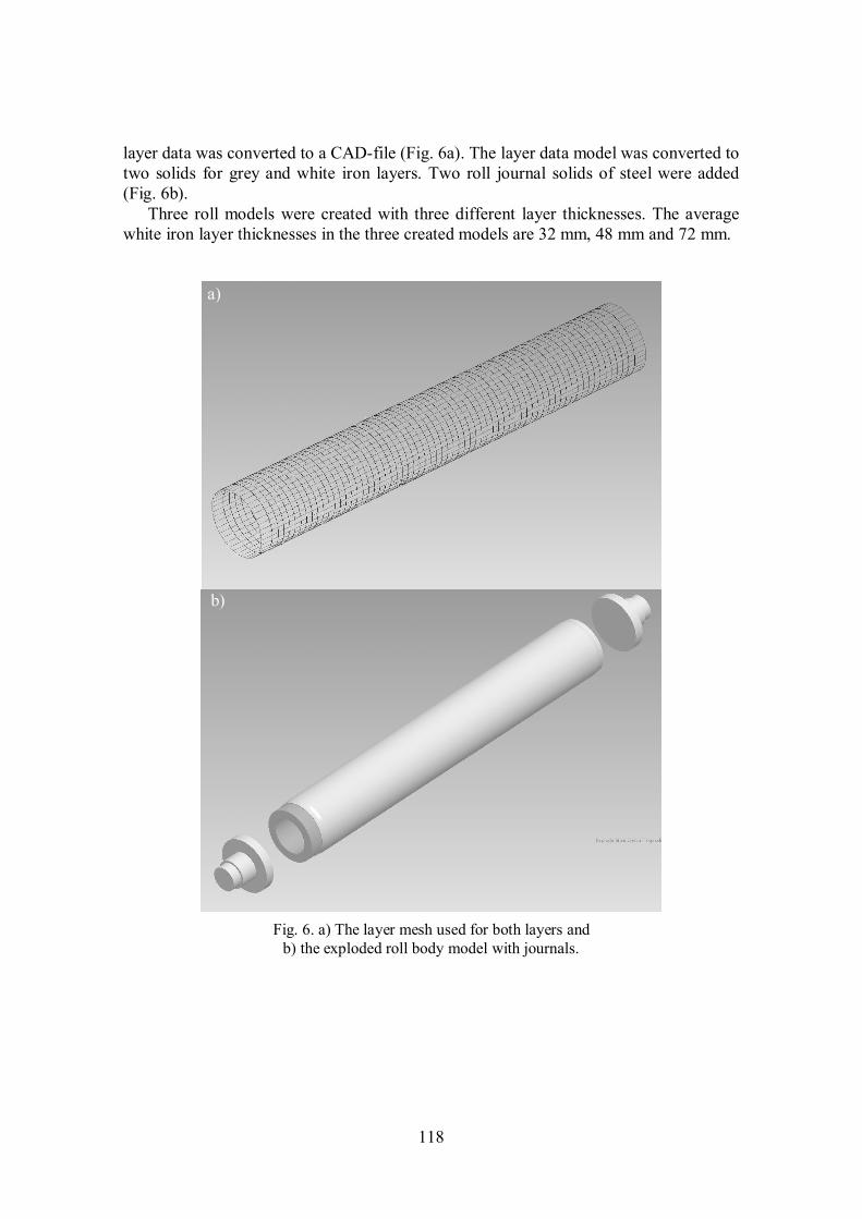
layer data was converted to a CAD-file (Fig. 6a). The layer data model was converted to two solids for grey and white iron layers. Two roll journal solids of steel were added (Fig. 6b).
Three roll models were created with three different layer thicknesses. The average white iron layer thicknesses in the three created models are 32 mm, 48 mm and 72 mm.
Fig. 6. a) The layer mesh used for both layers and
b) the exploded roll body model with journals.
a)
b)

119
Table 1. Properties of the iron phases and steel. [8]
Material E [GPa] ν ρ [kgm-3] α [10-6K-1] c [ms-1] white iron 172 0.27 7694 9.0 5796 mottle iron 131 0.27 7583 9.9 5198 grey iron 103 0.27 7334 10.8 4600 steel 207 0.30 7835 11.16 5900
These thicknesses represent actual white iron layer thicknesses of 10 mm, 16 mm
and 24 mm respectively. The modelled white iron layer border is in the middle of the actual mottle iron layer as can be seen from Fig. 1 and Fig. 4. The three modelled layer borders were created from the calculated layer thickness data (Fig. 5) by scaling.
The three models were used as input in Abaqus FEM software. Material properties are presented in Table 1. Properties of mottle iron are presented as additional infor-mation and they are not used in the analysis.
In Fig. 7 one of the created FE models is shown. The used element type is solid 4 node linear tetrahedron (Abaqus element type C3D4). In the FE model with white iron layer thickness of 72 mm the number of nodes is 40 000 and the number of elements is 157 000. In the other two models the used element type is the same tetrahedron and the element number is almost the same. The number of elements varies slightly, because the thickness of the white iron and grey iron layer varies.
The FE analyses of all three models are done with the same boundary conditions. The journal ends are tied to the roll shell ends. The roll models are simply supported at the journal ends. This means that the centre point of the end of one of the journals is locked in x, y and z directions and the other journal's end in x and y directions. A sup-plementary node in the first journal end is locked in x and y direction. These boundary conditions allow the roll to expand axially and they keep it from rotating, but do not prevent the deflection of the roll. The boundary condition sets at the journals are inter-changed in the second round of calculations. This is done to evaluate their influence on the results. Locking in all directions is applied in the first round of FE analyses on the service side journal axis end and in the second calculation round on the drive side jour-nal axis end. This evaluation is done only with 16 mm white iron thickness. Tempera-tures used in the calculations are in the initial step 20 °C for all elements. In the next step the temperature propagates to 150 °C in the grey iron layer and to 125 °C in the white iron layer. In the final step all elements in the roll have a temperature of 150 °C. The chosen temperature values were measured from the test thermo roll under operating conditions.
As discussed in the introduction, the chilled cast iron thermo rolls can deflect under thermal load in the paper machine. This deflection introduces run-out in the rotating roll. The first harmonic component of the FFT analysis of the run-out gives the ampli-tude and the phase angle (direction) of the deflection. [6]
The results from the FE analyses were analyzed to find out any geometry changes in the roll body. To find out the theoretical run-out of the roll model, the profile from 9 roll body cross sections were calculated from the result file of the FEM software. The first harmonic components (1H) of the cross section profiles were obtained with FFT analy-sis. The possible deflection of the roll model can be observed in these components.

120
Fig. 7. The element model of the roll and the directions of the used coordinates.
Results
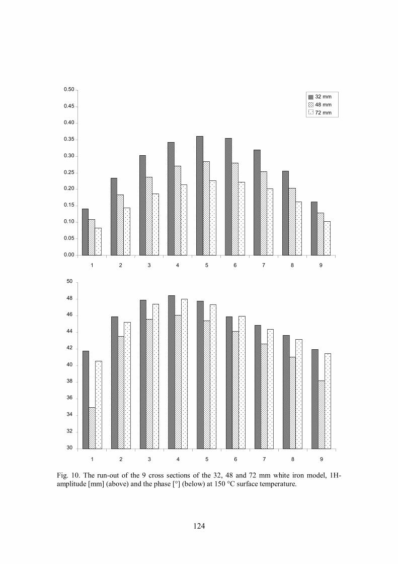
The results presented here are the amplitudes and phase angles of the first harmonic components from the 9 equally distanced (0.8 m) roll shell cross section profiles. Sec-tion 1 is on the service side 0.2 m from the roll body end and section 9 is 0.2 m from roll shell end on the drive side.
The chosen boundary conditions have only a small effect on the amplitude and slightly larger effect on the phase, as can be seen in the Fig. 8. In the figure the ampli-tudes and phases from the roll model with 32 mm white iron layer with both boundary condition sets and with both surface temperatures are presented. The maximum differ-ences in the phases are close to the drive side end. The reason for this is not known. It is also observed that the temperature difference in the layers increases the deflection of the roll. The cause for the deflection is the difference of the thermal expansion between the layers. The temperature difference increases the expansion differences of the layers, thus increasing the deflection.
The results show also that the thinner white iron layer causes a larger deflection, as shown in Fig. 9 and Fig. 10, where the amplitudes and phases of the different white iron layer thickness models are presented. The layer thickness has a small effect on the phase angles. When the temperature difference between the iron layers disappears the ampli-tude of the 1st harmonic component of the run-out decreases, but the in the phase angles remain practically the same.
Discussion
The results are consistent with previous studies and common knowledge about the be-haviour of the chilled cast iron thermo rolls. To be able to validate the results from the FE analyses there should be a run-out measurement from the test roll. There is a meas-

121
urement result from the test roll made with heating oil temperature at 150 °C. The rela-tion between the other measurement parameters and the boundary conditions of the FE analysis is not known. During a service visit of the roll at the manufacturer's roll shop, valves were installed in the heating oil bores to compensate the out of tolerance run-out the roll when used at operating temperature. The valves reduce the oil flow on the side of the roll where the run-out has its maximum, thus keeping this side of the roll cooler. This local lower temperature reduces the thermal deflection of the roll significantly. Re-gardless of the effects caused by the valves, the result of the run-out measurement is presented in Fig. 11.
Even though the calculated results are not comparable with the actual measurement, they are discussed to some extent. The evident difference is in the amplitude. Beside the fact that the installed valves reduce the run-out, another reason for this can be in the chosen material values. The material properties are chosen from different values found in the literature [8][9].
Also the boundary conditions of the FE model can have strong effect on the run-out. Their effect and possible better alternatives should be studied further. The temperature distribution in the model is simplified, thus very different from reality. In reality, the coefficient of thermal expansion is a function of temperature and in white iron also a function of material direction (Fig. 12). In the FEM software the coefficient can be a function and this should be changed in the future models.
The size of the thermal deflection of the roll is very sensitive to the values of these expansion coefficients. The values for the coefficients in the Table 1 are for pure white iron and for pure grey iron. As it can be seen in Fig. 1, the thickness of the pure white iron layer is practically non-existing. This means that the material values for the white iron layer are too high (as for E) or too low (as for α). A better value for these can be obtained by the integration over the depth of the white iron content in the outer layer. Very likely the content of the white iron in the grey iron layer can be neglected, i.e. no change in the values for the grey iron is necessary.
Temperature distribution of the measured roll is also affected by the depth of heating oil passages in the roll body. The heat transfer from passages closer to surface is more effective. The bore depths of the passages were also measured during the tests and the results are presented in Fig. 13. In the middle of the roll shell the depth variation is more than 15 mm. This can cause an uneven temperature distribution in the roll shell thus af-fecting the thermal deflection and its direction of the roll.
The nip pressure is also neglected in the model. The other roll in the calender can have an effect on the measured thermo roll. This effect is very likely dependant of the magnitude of the nip pressure.
The thermal deflection causes an unbalance in the roll. If the roll rotates (as during the run-out measurements or as during the paper production), this unbalance will in-crease the total run-out. If the centrifugal forces caused by the rotation are added to the FE models, the calculated amplitude of the run-out will increase even more. However, this is true only if the masses in the roll model are in balance. Normally, the direction of the thermal deflection is opposite to the side where the white iron layer thickness has its maximum in the roll shell. The density of white iron is higher thus causing an extra un

122
Fig. 8. The run-out of the 9 cross sections of the 32 mm white iron model, 1H-amplitude [mm] (above) and the phase [°] (below). Amplitudes and phases are from both boundary condition sets (service and drive side) and from both surface temperatures (125° C and 150 °C).
0.00
0.05
0.10
0.15
0.20
0.25
0.30
0.35
0.40
0.45
0.50
1 2 3 4 5 6 7 8 9
125 °C, Service side
125 °C, Drive side
150 °C, Service side
150 °C, Drive side
30
32
34
36
38
40
42
44
46
48
50
1 2 3 4 5 6 7 8 9

123
Fig. 9. The run-out of the 9 cross sections of the 32, 48 and 72 mm white iron model, 1H-amplitude [mm] (above) and the phase [°] (below) at 125 °C surface temperature.
0.00
0.05
0.10
0.15
0.20
0.25
0.30
0.35
0.40
0.45
0.50
1 2 3 4 5 6 7 8 9
32 mm 48 mm 72 mm
30
32
34
36
38
40
42
44
46
48
50
1 2 3 4 5 6 7 8 9
124
Fig. 10. The run-out of the 9 cross sections of the 32, 48 and 72 mm white iron model, 1H-amplitude [mm] (above) and the phase [°] (below) at 150 °C surface temperature.
0.00
0.05
0.10
0.15
0.20
0.25
0.30
0.35
0.40
0.45
0.50
1 2 3 4 5 6 7 8 9
32 mm 48 mm 72 mm
30
32
34
36
38
40
42
44
46
48
50
1 2 3 4 5 6 7 8 9

125
Fig. 11. Run-out measurement of the test roll in production conditions.
Fig. 12. Coefficients of the thermal expansion of the different iron phases as a function of the temperature [3].
400
Temperature [°C]
Coe
ff. o
f the
rmal
exp
ansi
on
x10-6
[°C
-1]
0
5
10
15
20
25
30
0 200 600 800 1000 1200
grey iron white iron (radial) white iron (axial)

126
Fig. 13. Ultrasonic measurement of the heating oil passage bore depths in the studied thermo roll shell. The measured thermo roll has 40 bores. The depth variation is more than 20 mm.
balance in the roll. If such a roll model is rotated (by adding the centrifugal forces) while it thermally deflects, it is quite possible that the amplitude of the total run-out de-creases, because of the unbalance caused by white iron layer (see Fig. 14). This can be also true for real paper machine rolls.
All modern fast rotating thermo rolls are balanced. Some of the rolls are even 'hot' balanced. It means that during the balancing process of the roll, the manufacturer tries to compensate the mass displacement effects caused by the thermal deflection described earlier.
Theoretically, a small thermal deflection could be compensated by a counterweight inside the roll. In case of the test roll, the size of the required mass would be too large to fit inside if made from steel or cast iron. Another disadvantage of 'balancing' of this kind is that the size of the deflection compensation is rotational speed dependant.
To validate the results from FE analyses, the test roll run-out measurements and the ultrasonic measurements should be repeated under controlled circumstances. The in-stalled valves should be removed or at least they should be fully open during the tests to allow normal oil flow in the bores. The exact material properties in the roll should also be measured. Normally, this cannot be done in a production roll, because the disman-tling of the roll is not allowed. The cooperation with the roll manufacturer can provide a solution to this problem.
In its present form the developed method can produce useful information about the thermo rolls, but if it is enhanced with the proposed corrections it will become an even better tool.
0
40
50
60
70
0 1000 2000 3000 400 5000 6000 7000
Bor
e de
pth
[mm
]
Roll shell length [mm]

127
Fig. 14. Unbalance forces caused by the thermal deflection and heavier white iron layer.
References
[1] SHW CT GmbH, "Steel Rolls?", Technical News Letter, Calender Rolls, No 13, December 2004
[2] Jokio, M., Papermaking Science and Technology, Papermaking Part 3, Finishing, Helsinki, Fapet Oy, 1999, ISBN 952-5216-10-1
[3] Jacot, A., Maijer, D., Cockcroft, S., Modelling of microstructure and residual stress in cast iron calender rolls, Metallurgical and material transactions A, Vol. 31A, April 2000, pp. 1201-1211
[4] Wirtz, W., Advanced thermo rolls for high speed modern calenders, 7th Interna-tional Conference on New Available Technologies, June 4-6, 2002, Stockholm, Sweden
[5] Boultbee, E., F., Schofield, G., A., Typical microstructures of cast metals, The In-stitute of British Foundrymen, IBF Publications, Birmingham, 1981
[6] Kiviluoma, P., Method and device for in situ runout measurement of calender thermo rolls, doctoral dissertation, Helsinki University of Technology, Espoo 2009, ISBN 978-952-248-259-4
[7] Uski, T., Ultrasonic inspection of the coating of paper machine rolls, in Finnish, Master's thesis, Helsinki University of Technology, Espoo, 1999
[8] Zwart, J., Farrel, W. R., Oxbow effect and surface temperature profiles of calender rolls, Pulp & Paper Canada, Vol. 93, No. 2, 1992, pp. T41-T47
[9] Rothenbacher, P., Vomhoff, E., Mass centering of chilled cast-iron rolls, Tappi Journal, Vol. 68, No. 7, July 1985
Thomas Widmaier Aalto University School of Engineering Department of Engineering Design and Production P.O.Box 14400, FI-00076 AALTO [email protected]
Grey ironDirection of the thermal deflection
White iron
Direction of the unbalance force caused by the thicker white iron layer