Embed Size (px)
Citation preview

Anthony MedellinDepartment of Engineering Technology &
Industrial Distribution,
Texas A&M University,
College Station, TX 77843
e-mail: [email protected]
Wenchao DuMem. ASME
Department of Industrial & Systems Engineering,
Texas A&M University,
College Station, TX 77843
e-mail: [email protected]
Guanxiong MiaoDepartment of Mechanical Engineering,
Texas A&M University,
College Station, TX 77843
e-mail: [email protected]
Jun ZouDepartment of Electrical &
Computer Engineering,
Texas A&M University,
College Station, TX 77843
e-mail: [email protected]
Zhijian PeiFellow ASME
Department of Industrial & Systems
Engineering,
Texas A&M University,
College Station, TX 77843
e-mail: [email protected]
Chao Ma1Mem. ASME
Department of Engineering Technology &
Industrial Distribution;
Department of Industrial & Systems Engineering;
Department of Mechanical Engineering,
Texas A&M University,
College Station, TX 77843
e-mail: [email protected]
Vat Photopolymerization3D Printing of Nanocomposites:A Literature ReviewNanocomposites have been widely used to improve material properties. Nanoscale rein-forcement materials in vat photopolymerization resins improve the hardness, tensilestrength, impact strength, elongation, and electrical conductivity of the printed products.This paper presents a literature review on the effects of reinforcement materials on nano-composite properties. Additionally, preprocessing techniques, printing processes, andpostprocessing techniques of nanocomposites are discussed. The nanocomposite proper-ties are summarized based on their applications in the mechanical, electrical and mag-netic, and biomedical industries. Future research directions are proposed to improve thematerial properties of printed nanocomposites. [DOI: 10.1115/1.4044288]
Keywords: nanocomposites, stereolithography, vat photopolymerization, 3D printing,material properties
1 Introduction
Additive manufacturing (AM) allows complex geometricaldesigns to be created without added tooling costs. It also allowssmall changes in design to be done without adding manufacturingcost. Another benefit of AM is the ability to print end-use partswith minimized material consumption. The ASTM standard [1]divides AM into seven categories, including vat photopolymeriza-tion, binder jetting, directed energy deposition, material extrusion,material jetting, powder bed fusion, and sheet lamination. Uniquefeatures of vat photopolymerization include the highest resolutionand smoothest surface finish of all additive manufacturingprocesses.
One of the drawbacks of vat photopolymerization is the limitedchoice in materials since the feedstock resin has to be
photopolymerizable. This limits the application space of theprinted parts. In order to print materials with various propertiesand expand the application space, nanoscale reinforcement mate-rials have been added to the base resin to form nanocomposites.Through the incorporation of nanoscale reinforcement materials,properties such as tensile strength, elastic modulus, hardness, andelectrical conductivity can be improved.
This review paper focuses on different resins and nanoscalereinforcements that have been used to print nanocomposites. Italso covers preprocessing techniques, common printer setups, cor-responding printing processes, and postprocessing techniques.The nanocomposite properties, including mechanical, electricaland magnetic, and biomedical, are discussed based on the differ-ent application areas. Finally, future directions are proposed toimprove equipment and feedstock materials.
2 Feedstock Material
The feedstock material for printing a nanocomposite by vatphotopolymerization is a suspension with nanoscale reinforce-ments suspended in a photopolymer resin. The resin forms the
1Corresponding author.Contributed by the Manufacturing Engineering Division of ASME for publication
in the JOURNAL OF MICRO- AND NANO-MANUFACTURING. Manuscript received March 28,2019; final manuscript received July 8, 2019; published online October 1, 2019.Assoc. Editor: Shih-Chi Chen.
Journal of Micro- and Nano-Manufacturing SEPTEMBER 2019, Vol. 7 / 031006-1CopyrightVC 2019 by ASME
Dow
nloaded from https://asm
edigitalcollection.asme.org/m
icronanomanufacturing/article-pdf/7/3/031006/6451804/jm
nm_007_03_031006.pdf by Texas A & M
University user on 10 April 2020

matrix of the resultant nanocomposite, while the reinforcementshelp to achieve desired properties for the targeted application.
2.1 Resins. The resin consists of monomers, oligomers, pho-toinitiators, diluents, and other additives. The monomers andoligomers are the basis of the resin, which get polymerized andcrosslinked when exposed to ultraviolet (UV) light. Photoinitia-tors decompose after exposure to light and become reactive. Next,the decomposed photoinitiators polymerize certain functionalgroups of the monomers and oligomers. The photoinitiator needsto be chosen according to the wavelength of the light source.Diluents are used to decrease the viscosity of the resin. This isespecially important with the incorporation of reinforcements in aresin as the reinforcements increase the viscosity. Other additivesinclude pigments, chain transfer agents, coupling agents, etc. [2].Pigment gives color to the polymer, while the chain transfer agentcontrols the amount of crosslinking in the polymer [3], and thecoupling agent improves the bond between the reinforcementmaterial and the resin [4]. The resins that have been studied arelisted in Table 1. The material selection for vat photopolymeriza-tion is limited. Research of nanocomposites is dominated byacrylates.
Different monomers can be mixed together to tailor the materialproperties. For example, in the experiment performed by dosSantos et al. [37], multiacrylate monomers (45–50%) and epoxies(15–25%) were used to improve the hardness and Young’s modu-lus of the nanocomposite with carbon nanotubes (CNTs). Most ofthe nonacrylate or nonepoxy resins have an acrylate end-groupfunctionalization. This functionalization makes the resin capableof being photopolymerized. Geven et al. [34], for instance, usedan acrylate end-group for functionalization of poly(trimethylenecarbonate) (PTMC). Similarly, acrylate was also used to function-alize poly(D,l-lactide) (PDLLA) [30].
The type of resin that should be chosen depends on the targetapplication and the compatibility with the reinforcement material.Materials with similar refractive indexes, such as acrylate-basedresin and silica, can be combined together to limit the Van derWaals attraction [5]. Matching the refractive indexes can alsoimprove the transparency of the slurry, and thus leading to higherresolution. This is because light scattering increases in less trans-parent resins, causing a decrease in resolution due to unwantedexposure of nearby monomers [5].
2.2 Reinforcements. Reinforcements affect the materialproperties and therefore the applications of the nanocomposite.The nanoscale reinforcements that were studied are listed inTable 2. The majority of nanocomposites studied use nanopar-ticles as the reinforcement material. The most studied reinforce-ment materials are silica nanoparticles, CNTs, and graphene oxidenanoplatelets. Of these reinforcement materials, silica is the mostresearched for use in nanocomposites. The mechanical properties,especially tensile strength, of nanocomposites are studied morethan their biomedical and electrical properties.
2.3 Viscosity of Feedstock. Viscosity is a very importantproperty of the feedstock. If the viscosity is too high, it will not
evenly fill the void created after the curing of the former layer andthe movement of the build platform. Defects in the part will resultfrom uneven filling. Additionally, a higher viscosity will lead to alonger print time as the resin will take longer to reflow to form anew uniform layer [6]. Diluents can be used to help reduce theviscosity of the resin. Moreover, increasing the temperature alsoleads to a decrease of the viscosity [5].
Parameters that affect the feedstock viscosity include the shearrate for testing and the amount and material of the reinforcement,as shown in Fig. 1. As shear rate increases, the viscosity decreasesfor different suspensions. Weng et al. [7] studied the effect ofshear rate on acrylate-based resins containing 10wt % silica nano-particles, attapulgite (ATP) nanorods, and organically modifiedmontmorillonite (OMMT) nanoplatelets. At a low shear rate of20Hz, the viscosity values for the silica-filled, ATP-filled and theOMMT-filled resins were 0.56 Pa�s, 1.7 Pa�s, and 0.78 Pa�s,respectively. At a shear rate of 1000Hz, the viscosity valuesachieved were 0.46 Pa�s by the silica, 0.36 Pa�s by the ATP, and0.33 Pa�s by the OMMT. As the shear rate increased, the nanopar-ticles deaggregated, the nanorods became oriented along thedirection of the shear force, and the nanoplatelets became stacked.
The shelf life of the suspension can be determined by the vis-cosity [8]. As the suspension ages, the viscosity increases, whichdepends on the reinforcement material and the filler amount.Larger reinforcement amounts cause a greater increase in viscos-ity over time, which can be related to the agglomeration of thereinforcement material. To overcome this problem, new resinshould be added to dilute the old resin to reduce its viscosity.
3 Preprocessing
Nanoscale reinforcements tend to agglomerate due to theirinterparticle forces. The agglomeration can lead to nonuniformityand degradation of the reinforcements. Mixing is a crucial prepro-cessing step to homogeneously disperse the reinforcement into theresin and avoid agglomeration.
There are different ways to mix the reinforcement material inthe matrix [3]. Frequently used methods include manual mixing,magnetic stirring, and sonication. Specifically, manual mixinguses a blade that stirs the mixture, and a high rotation speed isneeded to help reduce the mixing time. Magnetic stirring is simi-lar to manual mixing, in which a magnetic rod rotates at a highspeed to create a homogenous mixture. Both of these methods areeconomical in terms of the mixing step [3]. However, they cancause air bubbles in the resin, which will reduce the achievableresolution and cause defects in the final part. A vacuum is oftenused after stirring to help remove air bubbles from the mixtureand reclaim solvents. Weng et al. [7] used a planetary vacuumgravity mixer to remove air bubbles that were created during themixing process. Manapat et al. [9] used vacuum evaporation withmagnetic stirring to reclaim the acetone. The third commonlyused method to mix materials is sonication (<20 kHz) or ultra-sonication (>20 kHz), in which sound waves are used to dispersethe reinforcement material [27]. This method can also be usedinside a vacuum to aid in the air removal.
The suitable mixing method can be determined based on thematerials and the particle size. Some high-energy mixing proc-esses can damage the reinforcement material. For example, carbonnanotubes can be damaged by sonication [38]. They can undergosuch defects as buckling and bending. The mixing method canalso have an effect on the final particle size and distribution.According to Corcione et al. [10], magnetic stirring is better thansonication insofar that it creates a more stable and homogenousdispersion of the nanoparticles in the acrylate-based matrix withboehmite nanoparticles as the reinforcement material. Thisincrease in homogeneity was represented by the smaller standarddeviation of the average particle size right after mixing (1.42 nmfor sonication and 0.94 nm for magnetic stirring) and over a 30-day period (7.98 nm for sonication and 1.77 nm for magnetic stir-ring). The stability is demonstrated in the smaller change in
Table 1 Resins used for 3D printing of nanocomposites by vatphotopolymerization
Resin Reference
Acrylate [4–26]Epoxy [27–29]Poly(D,l-lactide) (PDLLA)-acrylate [30,31]Polypropylene fumarate (PPF) [32,33]Poly(trimethylene carbonate) (PTMC)-acrylate [34]Polyvinylsilazane (PVSZ)-acrylate [35]Vinylpyrrolidone (VP) [36]
031006-2 / Vol. 7, SEPTEMBER 2019 Transactions of the ASME
Dow
nloaded from https://asm
edigitalcollection.asme.org/m
icronanomanufacturing/article-pdf/7/3/031006/6451804/jm
nm_007_03_031006.pdf by Texas A & M
University user on 10 April 2020

Table 2 Nanocomposites investigated for vat photopolymerization
Reinforcement type Reinforcement material Base polymer Industry Material properties of interest Application Reference
Nanoparticle Boehmite Acrylate Mechanical Reinforcement material stabilityand homogeneity
Surface coating [10]
Nanoparticle Carbon black (CB) Acrylate Mechanical Hardness, tensile strength Rapid prototyping [20]Nanoparticle Cellulose nanocrystals (CNCs) Acrylate Biomedical Tensile strength, elongation,
fracture energyReconstructive surgery [12]
Nanoparticle Cellulose nanocrystals (CNCs) Epoxy Mechanical Tensile strength,Young’s modulus, storagemodulus
Rapid prototyping [27]
Nanoparticle Hydroxyapatite (HA) PDLLA-acrylate Biomedical Flexural modulus, flexuralstrength
Orthopedic surgery [30,31]
Nanoparticle Hydroxyapatite (HA) PPF Biomedical Cell adhesion and proliferation Bone tissue regeneration [33]Nanoparticle Hydroxyapatite (HA) PTMC-acrylate Biomedical Young’s modulus, tensile
strength, toughnessOrthopedic surgery [34]
Nanoparticle Lignin-coated cellulose nano-crystals (L-CNCs)
Acrylate Mechanical Tensile strength, Young’smodulus, elongation
Tissue engineering [7]
Nanoparticle Magnetite Acrylate Electrical Deflection Magnetic sensors [26]Nanoparticle Organically modified montmoril-
lonite (OMMT)Acrylate Mechanical Glass transition temperature Rapid prototyping [7]
Nanoparticle Polyvinyl pyrrolidone coatedgold
PPF Biomedical Biocompatibility, opticalabsorption
Scaffolds for delivery of thera-peutic agents
[32]
Nanoparticle Silica Epoxy Biomedical Hardness, impact strength, tensilestrength, flexural modulus
Dental models [28,29]
Nanoparticle Silica Acrylate, PVSZ-acrylate Mechanical Curing speed, resin loadingcapacity, hardness, volumetricshrinkage
Improved resin, rapidprototyping
[5,7,8,19,35]
Nanoparticle Silver Acrylate Electrical Resistivity, antimicrobialproperties
Sensing devices, biomedicalapplications
[15,18]
Nanoparticle Silver-coated lead zirconatetitanate
Acrylate Electrical Dielectric permittivity Capacitors [13]
Nanoparticle Titania Epoxy Biomedical Hardness, impact strength Dental models [28]Nanofiber ornanotube
Alumina Acrylate Mechanical Fiber alignment Tailored anisotropy, electricalinsulation
[4]
Nanofiber ornanotube
Attapulgite (ATP) Acrylate Mechanical Curing speed Improved resin [7]
Nanofiber ornanotube
Boehmite Acrylate Mechanical Flexural strength Manufacturing complexgeometries
[6]
Nanofiber ornanotube
Carbon nanotubes (CNTs) Acrylate Electrical, biomedical Conductivity Printed circuits, neuralregeneration
[11,14,23]
Nanofiber ornanotube
Carbon nanotubes (CNTs) Epoxy-acrylate Mechanical Young’s modulus, hardness Aeronautical [37]
Nanofiber ornanotube
sepiolite Epoxy Biomedical Hardness, impact strength Dental models [28]
Nanoplatelet Calcium phosphate layeredsilicate (CPLS)
Acrylate Mechanical Volumetric shrinkage, Young’smodulus
Rapid prototyping, tooling, andmanufacturing
[36]
Nanoplatelet Graphene VP Biomedical Cell metabolic activity Cell manipulation [28]Nanoplatelet Graphene oxide (GO) Epoxy Biomedical Hardness, impact strength Dental models [30]Nanoplatelet Graphene oxide (GO) Acrylate Mechanical, electrical Tensile strength, bending
strength, impact strength,conductivity
Rapid prototyping [9,21,22,24]
Nanoplatelet Molybdenum sulfide VP Biomedical Cell metabolic activity Cell manipulation [36]
JournalofMicro-andNano-M
anufacturin
gSEPTEMBER2019,Vol.7
/031006-3
Dow
nloaded from https://asm
edigitalcollection.asme.org/m
icronanomanufacturing/article-pdf/7/3/031006/6451804/jm
nm_007_03_031006.pdf by Texas A & M
University user on 10 April 2020

particle size over the 30-day period (9.21 nm for sonication and1.65 nm for magnetic stirring). However, the average size of thesonicated reinforcement particles (69.77 nm right after mixing and60.56 nm after 30 days) was about 20 nm less than that of the par-ticles which were magnetically mixed (86.07 nm right after mix-ing and 84.42 nm after 30 days).
Other methods that are used to mix the reinforcement materialand the matrix are high-shear homogenization and centrifugation.High-shear homogenization occurs when the mixture flowsthrough a rotor at high speeds. The centripetal force causes thematerial to flow through the stator, which breaks up the aggregatesto produce a homogenized mixture. Gonzalez et al. [11] used highshear homogenization to further disperse CNTs after sonication.Centrifugation can be used to remove large aggregates [36]. Aftercentrifugation, the larger particles migrate to the bottom due totheir higher density and then the top part of the centrifuged resincan be used.
Generally, one mixing method can be used in conjunction withothers to further facilitate mixing. For example, manual mixing iscommonly followed by sonication. Corcione et al. [10] subjectedthe acrylate-based resins with boehmite nanoparticles to
mechanical mixing, followed by sonication, magnetic mixing, andmore mechanical mixing. After preprocessing, it is vital that themixed resins are stored in a dark environment, which can inhibitthe prepolymerization of the resins.
4 Printing Processes
The printing process that should be chosen to create a partdepends on the feedstock materials and on the desired printingparameters. The printer used can be classified by the system con-figuration and the exposure strategy. Within these two main cate-gories, there can be additional components added to the printer toaid in achieving various printing performance.
4.1 System Configurations. There are two main system con-figurations for a vat photopolymerization printer: top down andbottom up. The difference between the two is the way the buildplatform moves after a layer is cured. Figure 2 shows a top downapproach. In a top down approach, the platform lies in the resinjust below the surface. The depth of the build platform in the resinis the layer thickness. After a layer is cured by light exposure, theplatform moves toward the bottom of the resin tank to allow fornew resin to flow in and the next layer to cure. A mechanical armcan be used to sweep more resin over the previous layer beforecuring.
The other method is the bottom up approach. This approach isdepicted in Fig. 3. The method works by the build platform layingthe cure depth away from the bottom of the resin tank. The bottomof the tank is transparent and the light is shone from underneaththe resin tank to polymerize the resin. Afterward, the build plat-form moves upward to allow for more resin to fill in for the nextlayer [39].
There are many advantages and disadvantages to both systemconfigurations. The top down approach requires much more mate-rial compared to the bottom up approach. This leads to an increasein costs and increase in material waste. For this reason, the bottomup approach is more widely used for printing nanocomposites.However, there is not as much stress on the printed part during theprinting process for the top down approach, since the bottom layeris not being sheared off after each layer is cured. This advantagecan lead to a larger print platform.
4.2 Exposure Strategies. There are two exposure strategiesfor vat photopolymerization, which are serial scanning and flood
Fig. 2 Top down approach with serial scanning Fig. 3 Bottom up approach with flood exposure
Fig. 1 Effects of reinforcement material and amount on viscos-ity at different shear rates
031006-4 / Vol. 7, SEPTEMBER 2019 Transactions of the ASME
Dow
nloaded from https://asm
edigitalcollection.asme.org/m
icronanomanufacturing/article-pdf/7/3/031006/6451804/jm
nm_007_03_031006.pdf by Texas A & M
University user on 10 April 2020
exposure. Serial scanning works by running a laser over the resinto selectively polymerize the resin, as is depicted in Fig. 2. In lit-erature, serial scanning is commonly referred to as stereolithogra-phy apparatus. Flood exposure, depicted in Fig. 3, selectivelycasts light on the layer according to the cross section of the part topolymerize the resin. This technique is faster since it is able topolymerize the whole layer simultaneously. This process is com-monly referred to as digital light processing.
One parameter related to exposure strategy is layer thickness.The layer thickness should be equal to or less than the cure depth,which is determined by Jacob’s equation [40]
Cd ¼ DplnðEmax=EcÞ (1)
where Cd is the cure depth (mm), Dp is the depth of penetration(mm) of the light source into the resin, Emax is the exposureenergy per unit area (J/cm2), and Ec is the critical exposure energyper unit area (J/cm2).
Delamination is a common issue during printing. It occurswhen adjacent layers are not bonded together because the resindoes not receive the necessary energy to get fully polymerized[41]. Delamination can be avoided if the layer thickness does notexceed the cure depth. The bonds between the layers becomestronger because of overcuring. The drawback of overcuring is adecrease in dimensional accuracy [12].
Layer thickness is also a key factor in part quality and printingspeed. Thicker layers allow parts to be printed faster at theexpense of the geometrical accuracy and surface smoothness.Smaller layer thicknesses lead to longer print times; however, theparts have a better surface finish and improved geometricalaccuracy.
4.3 Serial Scanning Techniques
4.3.1 Stereolithography Apparatus. The basic serial scanningtechnique uses a laser to selectively cure the polymer, which scansthe resin through the use of mirrors, as shown in Fig. 2. Lens canbe used to help focus the light. This process is able to achieve aresolution of 20lm [42]. The most commonly used wavelengthsare 355 nm and 405 nm. The 405 nm laser is usually more eco-nomical [43]. The 355 nm laser is within the range (310–355 nm),where most photoinitiators have maximum absorbance [44].
4.3.2 Two-Photon Polymerization. Two-photon polymeriza-tion is a type of nanoscale vat photopolymerization with resolu-tion capability of about 100 nm. In the experiment by Zhou et al.[45], a titanium–sapphire laser (780 nm wavelength) was attachedto an attenuator to control the power and then the laser beam wasexpanded to minimize the divergence angle and focused. The laser
beam is scanned across the surface of the resin using a galvo mir-ror system to polymerize the resin [46]. This technique greatlyimproves the printing resolution to 100 nm or less by using a pho-toinitiator that requires absorption of two photons and ultrashortlaser pulses.
4.4 Flood Exposure Techniques
4.4.1 Digital Light Processing. This process relies on a digitalmicromirror device to project different light patterns for differentlayers to polymerize the resin, as shown in Fig. 3. This methodcan produce 100 layers in 10 s [43] and has a significantly shorterprint time in comparison to the serial scanning technique. Bottom-up digital light processing setup also allows for easy accommoda-tion of fiber alignment mechanisms if needed [4,47].
4.4.2 Continuous Liquid Interface Production. This processhas an oxygen-permeable window made of a glass membrane,through which ultraviolet images are projected continuously intothe resin tank. The glass membrane restricts photopolymerizationbetween the polymer and the resin at the bottom of the tank byoxygenating the resin to create a dead zone. In the dead zone, theoxygen is more prevalent than the free radicals produced by thedecomposition of the photoinitiators, so photopolymerization isinhibited. Outside of the dead zone, free radicals are more preva-lent and so the photopolymerization of the resin can occur [48].Out of all the vat photopolymerization techniques, continuous liq-uid interface production has the highest printing speed [49].
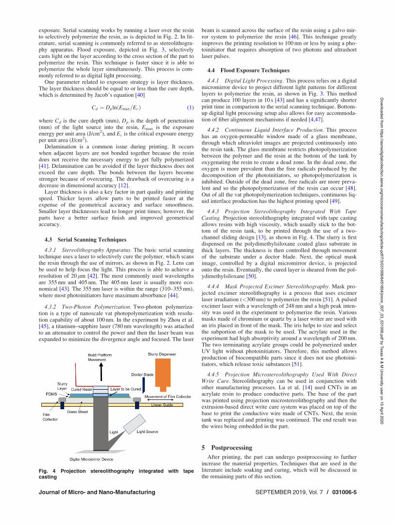
4.4.3 Projection Stereolithography Integrated With TapeCasting. Projection stereolithography integrated with tape castingallows resins with high viscosity, which usually stick to the bot-tom of the resin tank, to be printed through the use of a two-channel sliding design [13], as shown in Fig. 4. The slurry is firstdispensed on the polydimethylsiloxane coated glass substrate inthick layers. The thickness is then controlled through movementof the substrate under a doctor blade. Next, the optical maskimage, controlled by a digital micromirror device, is projectedonto the resin. Eventually, the cured layer is sheared from the pol-ydimethylsiloxane [50].
4.4.4 Mask Projected Excimer Stereolithography. Mask pro-jected excimer stereolithography is a process that uses excimerlaser irradiation (<300 nm) to polymerize the resin [51]. A pulsedexcimer laser with a wavelength of 248 nm and a high peak inten-sity was used in the experiment to polymerize the resin. Variousmasks made of chromium or quartz by a laser writer are used withan iris placed in front of the mask. The iris helps to size and selectthe subportion of the mask to be used. The acrylate used in theexperiment had high absorptivity around a wavelength of 200 nm.The two terminating acrylate groups could be polymerized underUV light without photoinitiators. Therefore, this method allowsproduction of biocompatible parts since it does not use photoini-tiators, which release toxic substances [51].
4.4.5 Projection Microstereolithography Used With DirectWrite Cure. Stereolithography can be used in conjunction withother manufacturing processes. Lu et al. [14] used CNTs in anacrylate resin to produce conductive parts. The base of the partwas printed using projection microstereolithography and then theextrusion-based direct write cure system was placed on top of thebase to print the conductive wire made of CNTs. Next, the resintank was replaced and printing was continued. The end result wasthe wires being embedded in the part.
5 Postprocessing
After printing, the part can undergo postprocessing to furtherincrease the material properties. Techniques that are used in theliterature include soaking and curing, which will be discussed inthe remaining parts of this section.
Fig. 4 Projection stereolithography integrated with tapecasting
Journal of Micro- and Nano-Manufacturing SEPTEMBER 2019, Vol. 7 / 031006-5
Dow
nloaded from https://asm
edigitalcollection.asme.org/m
icronanomanufacturing/article-pdf/7/3/031006/6451804/jm
nm_007_03_031006.pdf by Texas A & M
University user on 10 April 2020
5.1 Soaking. Soaking removes impurities [12] and unexposedresin [3]. This process is done by rinsing a part several times witha solution or putting a part in an agitated bath. Palaganas et al.[12] soaked the cellulose-nanocrystals-reinforced diacrylate partin phosphate buffered saline to allow the removal of impurities. Ina similar way, printed acrylate/GO was soaked in isopropyl alco-hol [9]. Silver-reinforced acrylate nanocomposites were soaked inisopropanol hexane in a sonication bath [15], which helpedremove uncrosslinked polymer chains. Epoxy-based resins can besoaked in a different solution. For example, tripropylene glycolmethyl ether was used to remove unreacted epoxy-based resin[29].
5.2 Curing. Curing allows further polymerization and cross-linking of the part. This process can tailor the properties to thedesired values through the control of the temperature or the expo-sure to various light sources. Exposure to mercury lamps [11], UVlight [16], or ovens [17] has showed an improved Young’s modu-lus. Manapat et al. [12] annealed acrylate/GO (1wt %) samples.The results showed that an annealing at 100 �C for 12 h increasedthe tensile strength from 91MPa to 1229MPa and the modulusfrom 7.7MPa to 59.6MPa. The article states that the increase ofproperties is due to better cross-linking, removal of water in thepart, and smaller pore sizes. Fantino et al. [18] subjected thesilver-reinforced acrylate samples to various curing temperaturesin air and in a vacuum. The samples that were heated in a vacuumwere more electrically conductive compared with those that wereheated in air. Moreover, the higher temperatures also led to anincrease in electrical conductivity. The drawback of curing is thatthe parts can undergo warping and shrinkage.
6 Achieved Properties
The effects of nanoscale reinforcement materials on the mate-rial properties of the part are reviewed in this section. The proper-ties are divided into mechanical, electrical and magnetic, andbiomedical properties.
6.1 Mechanical. Photopolymers tend to be brittle, especiallyfor acrylate-based ones. Reinforcements have been added toimprove the mechanical properties [27]. The improved mechani-cal properties allow the nanocomposites to be used for more appli-cations. Better properties allow end-use parts to be manufactured,rather than just prototypes. The achievable mechanical properties
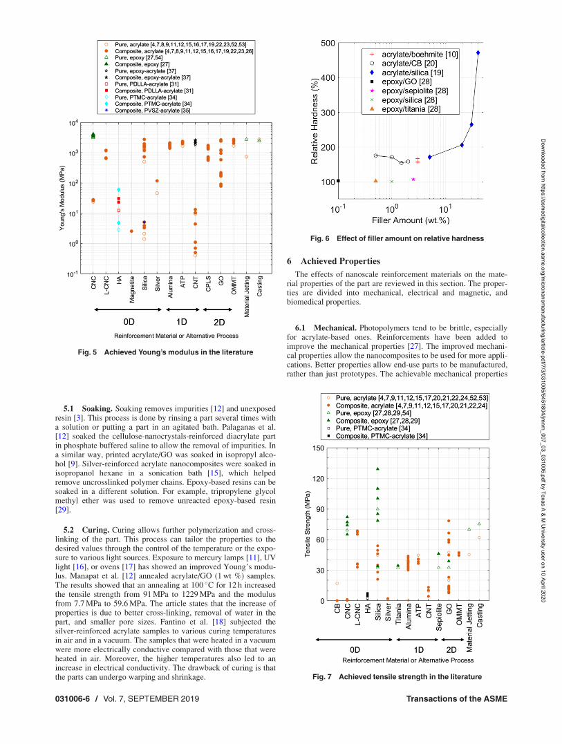
Fig. 5 Achieved Young’s modulus in the literature
Fig. 6 Effect of filler amount on relative hardness
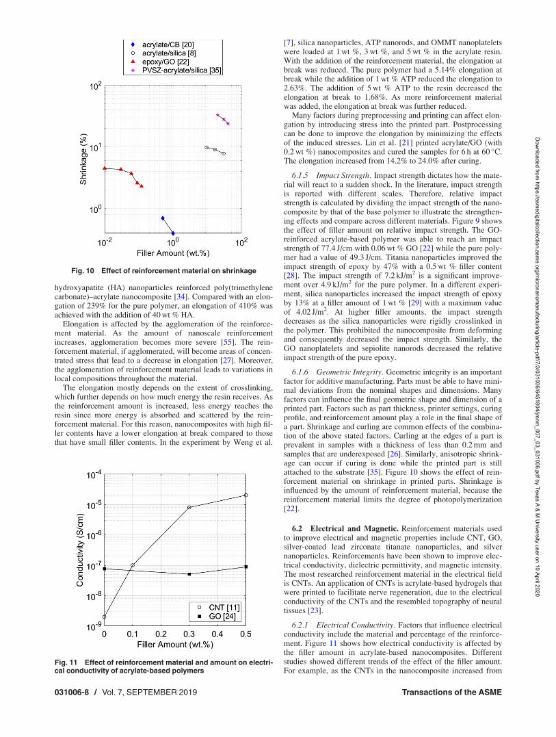
Fig. 7 Achieved tensile strength in the literature
031006-6 / Vol. 7, SEPTEMBER 2019 Transactions of the ASME
Dow
nloaded from https://asm
edigitalcollection.asme.org/m
icronanomanufacturing/article-pdf/7/3/031006/6451804/jm
nm_007_03_031006.pdf by Texas A & M
University user on 10 April 2020

by vat photopolymerization are summarized and compared withthose by 3D printing process (i.e., material jetting) and conven-tional manufacturing process (i.e., casting) [52–54].
6.1.1 Young’s Modulus. Young’s modulus, also known aselastic modulus, is an important property that helps to determinehow the material will respond to external stresses. The addition ofreinforcement materials can affect the Young’s modulus signifi-cantly. For example, OMMT nanoplatelets increase the modulusof an acrylate-based resin from 1660MPa to 2820MPa at a 5wt% filler amount [7]. However, the reinforcement made the nano-composites more brittle.
Since mechanical properties of fiber-reinforced nanocompositesdepend on the fiber orientation, technique has been developed tohelp align the fibers during processing. In the work by Yunuset al. [4], a lateral oscillation mechanism was implemented andcombined with wall pattern printing technique to generate shearflow to align the aluminum oxide nanofibers (2–6 nm in diameterand 200–400 nm in length) in the acrylate matrix nanocomposites.The elastic modulus and tensile strength were improved by 34%and 28%, respectively, with 1.5 vol % aligned aluminum oxidenanofibers when compared to the base acrylate.
Figure 5 shows the achieved Young’s modulus for various rein-forcement materials in the literature. The epoxy nanocompositesoften have significantly higher Young’s modulus over the acrylatenanocomposites because of their stronger base polymer. The bestYoung’s modulus was achieved with the incorporation of cellulosenanocrystals (CNC) in an epoxy-based nanocomposite. With the addi-tion of 3.89vol % CNC, a value of 4100MPa was achieved, which issignificantly higher than the 3100MPa of the pure epoxy [27].
6.1.2 Hardness. In the literature, hardness is reported withdifferent scales. Therefore, relative hardness is calculated bydividing the hardness of the nanocomposite by that of the basepolymer to illustrate the strengthening effects and compare acrossdifferent materials. Figure 6 shows the effect of filler amount onrelative hardness. As shown in the figure, the effect of
reinforcement on hardness is significant in acrylate-based nano-composites reinforced with silica nanoparticles [19]. The hardnessincreased from 3.4MPa (pure acrylate-based polymer) to 16 MPa(40wt % of silica nanoparticles as reinforcement material), whichgave a relative hardness of 470%. Carbon black nanoparticlesincreased the hardness of acrylate-based polymer by 75% at a fil-ler content of 0.5wt % [20]. The hardness improved from 48 HAfor the pure polymer to 84 HA for the nanocomposite.
Epoxy-based nanocomposites are able to achieve high hardnessvalues, even though the effect of reinforcement material is not assignificant as in acrylate-based nanocomposites. Wang and Ni[28] achieved a hardness of 122 HRR with 2.5wt % sepiolitenanorods as reinforcement in an epoxy-based nanocomposite. Theincreased hardness stems from the higher stiffness of the rein-forcement material.
6.1.3 Tensile Strength. Tensile strength is a key mechanicalproperty in the design of products as it helps to determine the loadthat the part can withstand. Figure 7 shows the effect of reinforce-ments on tensile strength of nanocomposites. The base resin alsoplays a key role in the tensile strength, since the polymer bonds ofthe printed part are the dominant intramolecular force. As a result,epoxy-based nanocomposites tend to have a greater tensilestrength compared to acrylate-based ones. The greatest valueswere achieved with silica in an epoxy-based polymer [29]. At a2wt % filler amount, the tensile strength reached 129.1MPa, com-pared to the pure polymer value of 89.9MPa. If too much rein-forcement material is added, it will begin to agglomerate,resulting in decreased tensile strength. In the same study by Liuand Mo [29], the highest tensile strength was achieved at 2wt %silica nanoparticles. At 3wt %, the tensile strength decreased to100.3MPa and continued to decrease for higher concentrations ofsilica nanoparticles. The highest amount of silica was 5wt % andhad a tensile strength of 78.5MPa. It should be noted that this islower than pure polymer value of 89.9MPa.
6.1.4 Elongation. Elongation at break is a key factor in deter-mining the ductility of a material. As is shown by Fig. 8, elonga-tion is not greatly affected by the addition of reinforcementmaterial. In the literature, the highest elongation was achieved by
Fig. 8 Achieved elongation in the literature Fig. 9 Effect of filler amount on relative impact strength
Journal of Micro- and Nano-Manufacturing SEPTEMBER 2019, Vol. 7 / 031006-7
Dow
nloaded from https://asm
edigitalcollection.asme.org/m
icronanomanufacturing/article-pdf/7/3/031006/6451804/jm
nm_007_03_031006.pdf by Texas A & M
University user on 10 April 2020
hydroxyapatite (HA) nanoparticles reinforced poly(trimethylenecarbonate)–acrylate nanocomposite [34]. Compared with an elon-gation of 239% for the pure polymer, an elongation of 410% wasachieved with the addition of 40wt % HA.
Elongation is affected by the agglomeration of the reinforce-ment material. As the amount of nanoscale reinforcementincreases, agglomeration becomes more severe [55]. The rein-forcement material, if agglomerated, will become areas of concen-trated stress that lead to a decrease in elongation [27]. Moreover,the agglomeration of reinforcement material leads to variations inlocal compositions throughout the material.
The elongation mostly depends on the extent of crosslinking,which further depends on how much energy the resin receives. Asthe reinforcement amount is increased, less energy reaches theresin since more energy is absorbed and scattered by the rein-forcement material. For this reason, nanocomposites with high fil-ler contents have a lower elongation at break compared to thosethat have small filler contents. In the experiment by Weng et al.
[7], silica nanoparticles, ATP nanorods, and OMMT nanoplateletswere loaded at 1wt %, 3wt %, and 5wt % in the acrylate resin.With the addition of the reinforcement material, the elongation atbreak was reduced. The pure polymer had a 5.14% elongation atbreak while the addition of 1wt % ATP reduced the elongation to2.63%. The addition of 5wt % ATP to the resin decreased theelongation at break to 1.68%. As more reinforcement materialwas added, the elongation at break was further reduced.
Many factors during preprocessing and printing can affect elon-gation by introducing stress into the printed part. Postprocessingcan be done to improve the elongation by minimizing the effectsof the induced stresses. Lin et al. [21] printed acrylate/GO (with0.2wt %) nanocomposites and cured the samples for 6 h at 60 �C.The elongation increased from 14.2% to 24.0% after curing.
6.1.5 Impact Strength. Impact strength dictates how the mate-rial will react to a sudden shock. In the literature, impact strengthis reported with different scales. Therefore, relative impactstrength is calculated by dividing the impact strength of the nano-composite by that of the base polymer to illustrate the strengthen-ing effects and compare across different materials. Figure 9 showsthe effect of filler amount on relative impact strength. The GO-reinforced acrylate-based polymer was able to reach an impactstrength of 77.4 J/cm with 0.06wt % GO [22] while the pure poly-mer had a value of 49.3 J/cm. Titania nanoparticles improved theimpact strength of epoxy by 47% with a 0.5wt % filler content[28]. The impact strength of 7.2 kJ/m2 is a significant improve-ment over 4.9 kJ/m2 for the pure polymer. In a different experi-ment, silica nanoparticles increased the impact strength of epoxyby 13% at a filler amount of 1wt % [29] with a maximum valueof 4.02 J/m2. At higher filler amounts, the impact strengthdecreases as the silica nanoparticles were rigidly crosslinked inthe polymer. This prohibited the nanocomposite from deformingand consequently decreased the impact strength. Similarly, theGO nanoplatelets and sepiolite nanorods decreased the relativeimpact strength of the pure epoxy.
6.1.6 Geometric Integrity. Geometric integrity is an importantfactor for additive manufacturing. Parts must be able to have mini-mal deviations from the nominal shapes and dimensions. Manyfactors can influence the final geometric shape and dimension of aprinted part. Factors such as part thickness, printer settings, curingprofile, and reinforcement amount play a role in the final shape ofa part. Shrinkage and curling are common effects of the combina-tion of the above stated factors. Curling at the edges of a part isprevalent in samples with a thickness of less than 0.2mm andsamples that are underexposed [26]. Similarly, anisotropic shrink-age can occur if curing is done while the printed part is stillattached to the substrate [35]. Figure 10 shows the effect of rein-forcement material on shrinkage in printed parts. Shrinkage isinfluenced by the amount of reinforcement material, because thereinforcement material limits the degree of photopolymerization[22].
6.2 Electrical and Magnetic. Reinforcement materials usedto improve electrical and magnetic properties include CNT, GO,silver-coated lead zirconate titanate nanoparticles, and silvernanoparticles. Reinforcements have been shown to improve elec-trical conductivity, dielectric permittivity, and magnetic intensity.The most researched reinforcement material in the electrical fieldis CNTs. An application of CNTs is acrylate-based hydrogels thatwere printed to facilitate nerve regeneration, due to the electricalconductivity of the CNTs and the resembled topography of neuraltissues [23].
6.2.1 Electrical Conductivity. Factors that influence electricalconductivity include the material and percentage of the reinforce-ment. Figure 11 shows how electrical conductivity is affected bythe filler amount in acrylate-based nanocomposites. Differentstudies showed different trends of the effect of the filler amount.For example, as the CNTs in the nanocomposite increased from
Fig. 10 Effect of reinforcement material on shrinkage
Fig. 11 Effect of reinforcement material and amount on electri-cal conductivity of acrylate-based polymers
031006-8 / Vol. 7, SEPTEMBER 2019 Transactions of the ASME
Dow
nloaded from https://asm
edigitalcollection.asme.org/m
icronanomanufacturing/article-pdf/7/3/031006/6451804/jm
nm_007_03_031006.pdf by Texas A & M
University user on 10 April 2020

0wt % to 1wt %, the electrical conductivity increased from2� 10�9 S/cm to 4� 10�4 S/cm [11]. In another study, however,0.3wt % of GO decreased the conductivity and 0.5wt % increasedthe electrical conductivity of the nanocomposite [24].
The electrical conductivity of fiber-reinforced nanocompositesdepends on the fiber orientation when conductive fibers are used.Greenhall and Raeymaekers used ultrasound transducers fornickel-coated carbon fiber alignment [47]. The resin tank was sur-rounded by eight ultrasound transducers in an octagonal pattern.The waves produced by the ultrasound transducers caused thefibers to agglomerate at the nodes. The resultant material showedanisotropic electrical conductivity: the resistance between twopoints with a distance of 1mm along the fiber direction was 59.7X while that across the fiber direction was 112.7 X. A bottom upapproach with flood exposure was used, allowing each layer tohave a different orientation of fibers to produce functionally com-plex parts.
Some post-treatments, like an UV exposure and a thermal post-treatment, also affect the electrical conductivity. Chiappone et al.[24] studied how different postprocessing techniques affect theconductivity of nanocomposites. Acrylate/GO (0.3wt %) nano-composites were subjected to either a thermal post-treatment at70 �C for 24 h or a UV light exposure for 1 h [19]. The thermaltreatment increased the electrical conductivity of the nanocompo-sites from 50.8 nS/cm to 109.5 nS/cm, whereas the UV exposuredecreased the electrical conductivity to 15.72 nS/cm.
In the experiment by Fantino et al. [18], 15wt % of silvernitrate (AgNO3) was incorporated in an acrylate matrix. Postpro-cessing of the nanocomposites showed that increases in tempera-ture and time allowed for the nanoparticles to increase in size andbecome more tightly packed. As the temperature increased from100 to 200 �C, the electrical conductivity increased from 0.22 lS/cm to 2.4 lS/cm after 1 h of heat treatment. One thing that shouldbe noted is that the nanocomposite should not be heated to thepoint where oxidation occurs to avoid a decrease of electrical con-ductivity. For this reason, a vacuum is usually used to avoid theoxidation and consequently improve the electrical conductivity.
6.2.2 Dielectric Permittivity. Dielectric permittivity is thelevel of electrical polarization a material experiences under anexternal electric field. The dielectric permittivity of materials isstudied for use in capacitors and dielectric resonators. This electri-cal property can be improved by nanocomposites. Yang et al. [13]improved the dielectric permittivity of the capacitors using silver-coated lead zirconate titanate nanoparticles as the reinforcementmaterial in an acrylate-based resin. The 3D printed capacitor has aspecific capacitance of 63 F/g at a current density of 0.5A/g. Thedielectric permittivity increased as the reinforcement amountincreased. At 100Hz, the dielectric permittivity increased from 4for the pure polymer to 120 with 18 vol % of reinforcement mate-rial with a dielectric loss of 0.028. The high dielectric permittivityand low dielectric loss make the nanocomposite a strong candi-date for capacitor applications.
6.2.3 Magnetic Intensity. The magnetic property of 3Dprinted parts has been studied for use in microelectromechanicalsystems. Credi et al. [26] compared the deflection behaviorsof two different microcantilevers made of acrylate/magnetite(1 vol %) and pure acrylate plated with magnetic alloy (NiCoP).When a permanent magnet was moved from 20mm to 19mmfrom the cantilever, a 190lm deflection was observed by thenanocomposite cantilever and a 115lm deflection was observedby the electroless plated cantilever. The results show that thenanocomposite cantilever has larger deflections than the electro-less plated cantilever, making this nanocomposite a strong candi-date for sensors or actuators.
6.3 Biomedical. Additive manufacturing has a strong capa-bility of creating customized parts [17]. As one of the most promi-nent applications, the medical field acts as an important driving
factor for the development of printing nanocomposites by the vatphotopolymerization process. Many reinforcement materials andresins have been researched for their feasibility in the medicalfield. Some nanocomposites have good bioactivity and biocompat-ibility, which allows them to be used for tissue engineering [31].
6.3.1 Cell Manipulation. The incorporation of reinforcementmaterial affects the bioactivity of cell culture media. Grapheneand molybdenum sulfide were used as the reinforcement materialsfor a polyvinylpyrrolidone-based polymer to print hydrogels asthe media for cell culturing [17]. The reinforcements improvedthe metabolic activity of the cultured cells. After culturing for168 h, the nanocomposites showed signs of cell aggregates. Themolybdenum sulfide in a polyvinylpyrrolidone-based nanocompo-site changed the shape of the endothelial cells from a roundedmorphology to a more outstretched morphology. The study con-tributed this shape change to the different ways of cell adherence.Furthermore, a change in morphology allows the cell to intakemore nutrients [56] and thus enables the improvement of the met-abolic activity of the cells.
6.3.2 Drug Delivery. Nanocomposite scaffolds have beenstudied for delivery of therapeutic agents. Abdelrasoul et al. [32]used gold nanoparticles coated with polyvinyl pyrrolidone to rein-force polypropylene fumarate for printing scaffolds. The nano-composite scaffolds can use the nanoparticles to transport thetherapeutic agents such as deoxyribonucleic acid or ribonucleicacid. Nanocomposite scaffolds were implanted in mice andremoved after 2weeks. There were no immune responses from themice. This shows that the mice did not reject the nanocomposite.The inherent inertness and nontoxicity of gold make it an idealnanofiller for scaffolds that provide a new delivery strategy ofdrug molecules, large biomolecules, and proteins.
6.3.3 Bone Tissue Engineering. Hydroxyapatite (HA,Ca5(PO4)3(OH)) nanopowder was used with dimethacrylate forbone tissue engineering. This nanocomposite can be used to printbone scaffolds for orthopedic surgery. Ronca et al. [31] used HAwith PDLLA-acrylate to study how nanocomposite scaffoldsaffect cell growth. Porous structures were printed to induce boneformation with human marrow mesenchimal cells. The scaffoldsallowed cell adhesion and had better results compared to tradi-tional methods. A polypropylene fumarate-based nanocompositecan also be used with HA. The seeded nanocomposite scaffoldsshowed better cell proliferation than the polymer scaffolds fromDay 1 to Day 14 of the study [33].
6.3.4 Dental Implants. Sepiolite nanofibers, GO, titania, andsilica nanoparticles with an epoxy-based resin can be used in den-tal applications due to their excellent mechanical properties andbiocompatibility [28]. The nanocomposite with sepiolite achievedthe highest hardness and tensile strength out of the tested nano-composites. The printed nanocomposites also achieve high dimen-sional accuracy. All of these improvements facilitate dental modelfabrication.
6.3.5 Reconstructive Tissue Surgery. Biocompatible rein-forcement materials can be mixed with base resins in tissue engi-neering to print implants. Cellulose nanocrystals (CNCs) andlignin-coated cellulose nanocrystals (L-CNCs) show potential foruse in reconstructive tissue surgery [17]. A human ear was printedwith an acrylate-based resin and CNCs as the reinforcement mate-rial [12]. The printed ear shows the capability of printed parts tobe used in microtia and anotia surgery.
7 Future Directions
7.1 Equipment Improvements. Advances in vat photopoly-merization printers are vital to print parts with a high amount ofreinforcement materials. The main problems associated with ahigh amount of reinforcement materials are high viscosity,
Journal of Micro- and Nano-Manufacturing SEPTEMBER 2019, Vol. 7 / 031006-9
Dow
nloaded from https://asm
edigitalcollection.asme.org/m
icronanomanufacturing/article-pdf/7/3/031006/6451804/jm
nm_007_03_031006.pdf by Texas A & M
University user on 10 April 2020
uncertainty in exposure parameters, and settling of reinforcementmaterials from the resin. The problem of high viscosity can beminimized through a temperature control of resins [5]. Anincrease in resin temperature will decrease the viscosity, whichwill help to make high-viscosity resins easier to print.
The ideal exposure parameters change significantly with differ-ent materials and amounts of reinforcements because of the com-plex interaction between the light and the reinforcement. Anunderexposure deteriorates the material properties while an over-exposure sacrifices the resolution. It is time consuming to searchfor the ideal exposure parameters of each nanocomposite materialby trial and error. This problem can be solved through an incorpo-ration of an online monitoring and control system that can detectwhether a layer is fully polymerized. Moreover, it will alsodecrease print time, since each layer is given the minimal amountof energy required to be fully polymerized.
The last major problem, settling of reinforcement materials, canbe solved through the incorporation of a type of mechanicalmixer. Yunus et al. [4] used a lateral oscillation mechanism toalign nanowires. The mechanism used shear force to align thenanowires in a specific direction. By adding a similar mechanismto printers, the reinforcement material can be agitated duringprinting to minimize settling and agglomeration of the reinforce-ment materials. This type of mechanism is especially importantfor parts with long print times.
7.2 Material Improvements. Common problems facingprinted parts are agglomeration of nanoscale reinforcements andinteraction of light and reinforcements. Material research is cru-cial to improve the achievable properties of printed parts. At highloading amounts, nanoscale reinforcement materials have a tend-ency to agglomerate, thus reducing the strengthening effects ofthe reinforcements and increasing the number of defects. There-fore, a high loading of reinforcement materials is currently hard toachieve. Resins that reduce the effects of agglomerations will helpto achieve a high loading of reinforcement materials and limit thenumber of defects in the printed part. This can be achievedthrough resins that have dispersants.
Reinforcement materials can significantly complicate the light-resin interaction. Without any reinforcements, the light is sup-posed to interact with the photoinitiator in the resin to start thephotopolymerization. However, some reinforcements have a highlight absorptivity, hindering the intended interaction between thelight and the photoinitiator and thus the photopolymerization ofthe resin. Also, the nanoscale reinforcements strongly scatter thelight, compromising the resolution. Research on novel photoinitia-tors and reinforcements is needed to maximize the light absorp-tion by the photoinitiators and minimize the light absorption andscattering by the reinforcements.
8 Conclusions
This paper provides a review on printing nanocomposites byvat photopolymerization, which has been increasingly researchedduring the past decade. Different resins and reinforcement materi-als are reviewed. Preprocessing methods are investigated, espe-cially their effects on agglomeration and viscosity. Variousprinting processes are described as well as their use. Effects of dif-ferent postprocessing techniques are investigated and reported.The properties of the nanocomposites are shown in the areas ofmechanical, electrical and magnetic, and biomedical. Finally,future directions to improve equipment and materials are proposedto improve nanocomposites made by vat photopolymerization.The equipment can be improved by incorporating resin vat tem-perature control to help overcome the increased viscosity fromintroduction of reinforcement materials, incorporating an onlinemonitoring and control system to detect when a layer is fully poly-merized, and incorporating a mechanical mixer to agitate the rein-forcement materials to minimize agglomerations and settling. Thematerials can be improved through research of novel dispersants
that minimize agglomerations. Also, new photoinitiators that havegreater absorbance around the wavelength of the light source mustbe researched to overcome settling of reinforcement materials.
Acknowledgment
This work is supported by the National Science Foundation(NSF) under REU Site Grant (No. EEC 1757882). Any opinions,findings, conclusions, or recommendations presented are those ofthe authors and do not necessarily reflect the views of the NationalScience Foundation. We also acknowledge the significant supportfor summer research and enrichment activities by Texas A&MCollege of Engineering’s Undergraduate Summer Research GrantProgram.
Nomenclature
AgNO3 ¼ silver nitrateCd ¼ cure depthCd ¼ Dp ln(Emax/Ec)DNA¼ deoxyribonucleic acidDp ¼ depth of penetrationEc ¼ critical exposure energy per unit area
Emax ¼ exposure energy per unit area
References[1] ASTM, 2015, “Standard Terminology for Additive Manufacturing—General
Principles—Terminology,” ASTM International. West Conshohocken, PA,Standard No. ISO/ASTM52900-15.
[2] Ligon, S. C., Liska, R., Stampfl, J., Gurr, M., and M€ulhaupt, R., 2017,“Polymers for 3D Printing and Customized Additive Manufacturing,” Chem.Rev., 117(15), pp. 10212–10290.
[3] Manapat, J. Z.,Chen, Q., Ye, P., and Advincula, R. C., 2017, “3D Printing ofPolymer Nanocomposites Via Stereolithography,” Macromol. Mater. Eng.,302(9), p. 1600553.
[4] Yunus, D. E., Shi, W., Sohrabi, S., and Liu, Y., 2016, “Shear Induced Align-ment of Short Nanofibers in 3D Printed Polymer Composites,” Nanotechnol-ogy, 27(49), p. 495302.
[5] Wozniak, M., de Hazan, Y., Graule, T., and Kata, D., 2011, “Rheology of UVCurable Colloidal Silica Dispersions for Rapid Prototyping Applications,” J.Eur. Ceram. Soc., 31(13), pp. 2221–2229.
[6] Han, Y., Wang, FKe., Wang, H., Jiao, X., and Chen, D., 2018, “High-StrengthBoehmite-Acrylate Composites for 3D Printing: Reinforced Filler-Matrix Inter-actions,” Compos. Sci. Technol., 154, pp. 104–109.
[7] Weng, Z., Zhou, Y., Lin, W., Senthil, T., and Wu, L., 2016, “Structure-PropertyRelationship of Nano Enhanced Stereolithography Resin for Desktop SLA 3DPrinter,” Compos. Part A: Appl. Sci. Manuf., 88, pp. 234–242.
[8] Gurr, M., Hofmann, D., Ehm, M., Thomann, Y., K€ubler, R., and M€ulhaupt, R.,2008, “Acrylic Nanocomposite Resins for Use in Stereolithography and Struc-tural Light Modulation Based Rapid Prototyping and Rapid ManufacturingTechnologies,” Adv. Funct. Mater., 18(16), pp. 2390–2397.
[9] Manapat, J. Z., Mangadlao, J. D., Tiu, B. D. B., Tritchler, G. C., and Advincula,R. C., 2017, “High-Strength Stereolithographic 3D Printed Nanocomposites:Graphene Oxide Metastability,” ACS Appl. Mater. Interfaces 9(11),pp. 10085–10093.
[10] Corcione, C. E., Cataldi, A., and Frigione, M., 2013, “Measurements of SizeDistribution Nanoparticles in Ultraviolet-Curable Methacrylate-Based Boeh-mite Nanocomposites,” J. Appl. Polym. Sci., 128(6), pp. 4102–4109.
[11] Gonzalez, G., Chiappone, A., Roppolo, I., Fantino, E., Bertana, V., Perrucci, F.,Scaltrito, L., Pirri, F., and Sangermano, M., 2017, “Development of 3D Print-able Formulations Containing CNT With Enhanced Electrical Properties,”Polymers, 109, pp. 246–253.
[12] Palaganas, N. B., Mangadlao, J. D., de Leon, A. C. C., Palaganas, J. O.,Pangilinan, K. D., Lee, Y. J., and Advincula, R. C., 2017, “3D Printing ofPhotocurable Cellulose Nanocrystal Composite for Fabrication of ComplexArchitectures Via Stereolithography,” ACS Appl. Mater. Interfaces, 9(39), pp.34314–34324.
[13] Yang, Y., Chen, Z., Song, X., Zhu, B., Hsiai, T., Wu, P.-I., Xiong, R., Shi, J.,Chen, Y., Zhou, Q., and Shung, K. K., 2016, “Three Dimensional Printing ofHigh Dielectric Capacitor Using Projection Based Stereolithography Method,”Nano Energy, 22, pp. 414–421.
[14] Lu, Y., Vatani, M., and Choi, J.-W., 2013, “Direct-Write/Cure ConductivePolymer Nanocomposites for 3D Structural Electronics,” J. Mech. Sci. Tech-nol., 27(10), pp. 2929–2934.
[15] Sciancalepore, C., Moroni, F., Messori, M., and Bondioli, F., 2017, “Acrylate-Based Silver Nanocomposite by Simultaneous Polymerization–ReductionApproach Via 3D Stereolithography,” Compos. Commun., 6, pp. 11–16.
[16] Gurr, M., Thomann, Y., Nedelcu, M., K€ubler, R., K€oncz€ol, L., and M€ulhaupt,R., 2010, “Novel Acrylic Nanocomposites Containing In-Situ Formed CalciumPhosphate/Layered Silicate Hybrid Nanoparticles for Photochemical Rapid Pro-totyping, Rapid Tooling and Rapid Manufacturing Processes,” Polymers,51(22), pp. 5058–5070.
031006-10 / Vol. 7, SEPTEMBER 2019 Transactions of the ASME
Dow
nloaded from https://asm
edigitalcollection.asme.org/m
icronanomanufacturing/article-pdf/7/3/031006/6451804/jm
nm_007_03_031006.pdf by Texas A & M
University user on 10 April 2020

[17] Feng, X., Yang, Z., Chmely, S., Wang, Q., Wang, S., and Xie, Y., 2017,“Lignin-Coated Cellulose Nanocrystal Filled Methacrylate Composites Pre-pared Via 3D Stereolithography Printing: Mechanical Reinforcement and Ther-mal Stabilization,” Carbohydr. Polym., 169, pp. 272–281.
[18] Fantino, E., Chiappone, A., Calignano, F., Fontana, M., Pirri, F., and Roppolo,I., 2016, “In Situ Thermal Generation of Silver Nanoparticles in 3D PrintedPolymeric Structures,” Materials, 9(7), p. 589.
[19] Chiappone, A., Fantino, E., Roppolo, I., Lorusso, M., Manfredi, D., Fino, P.,Pirri, C. F., and Calignano, F., 2016, “3D Printed PEG-Based Hybrid Nanocom-posites Obtained by Sol–Gel Technique,” ACS Appl. Mater. Interfaces, 8(8),pp. 5627–5633.
[20] Chiu, S.-H., Wicaksono, S. T., Chen, K.-T., Chen, C.-Y., and Pong, S.-H.,2015, “Mechanical and Thermal Properties of Photopolymer/CB (CarbonBlack) Nanocomposite for Rapid Prototyping,” Rapid Prototyping J., 21(3),pp. 262–269.
[21] Lin, D., Jin, S., Zhang, F., Wang, C., Wang, Y., Zhou, C., and Cheng, G. J.,2015, “3D Stereolithography Printing of Graphene Oxide Reinforced ComplexArchitectures,” Nanotechnology, 26(43), p. 434003.
[22] Li, J., Wang, L., Dai, L., Zhong, L., Liu, B., Ren, J., and Xu, Y., 2018,“Synthesis and Characterization of Reinforced Acrylate Photosensitive Resinby 2-Hydroxyethyl Methacrylate-Functionalized Graphene Nanosheets for 3DPrinting,” J. Mater. Sci., 53(3), pp. 1874–1886.
[23] Lee, S.-J., Zhu, W., Nowicki, M., Lee, G., Heo, D. N., Kim, J., Zuo, Y. Y., andZhang, L. G., 2018, “3D Printing Nano Conductive Multi-Walled CarbonNanotube Scaffolds for Nerve Regeneration,” J. Neural Eng., 15(1), p. 016018.
[24] Chiappone, A., Roppolo, I., Naretto, E., Fantino, E., Calignano, F., Sanger-mano, M., and Pirri, F., 2017, “Study of Graphene Oxide-Based 3D PrintableComposites: Effect of the in Situ Reduction,” Compos. Part B: Eng., 124, pp.9–15.
[25] Esposito Corcione, C.,Striani, R., Montagna, F., and Cannoletta, D., 2015,“Organically Modified Montmorillonite Polymer Nanocomposites for Stereoli-thography Building Process,” Polym. Adv. Technol., 26(1), pp. 92–98.
[26] Credi, C., Fiorese, A., Tironi, M., Bernasconi, R., Magagnin, L., Levi, M., andTurri, S., 2016, “3D Printing of Cantilever-Type Microstructures by Stereoli-thography of Ferromagnetic Photopolymers,” ACS Appl. Mater. Interfaces,8(39), pp. 26332–26342.
[27] Kumar, S., Hofmann, M., Steinmann, B., Foster, E. J., and Weder, C., 2012,“Reinforcement of Stereolithographic Resins for Rapid Prototyping With Cellu-lose Nanocrystals,” ACS Appl. Mater. Interfaces, 4(10), pp. 5399–5407.
[28] Wang, L., and Ni, X., 2017, “The Effect of the Inorganic Nanomaterials on theUV-Absorption, Rheological and Mechanical Properties of the Rapid Prototyp-ing Epoxy-Based Composites,” Polym. Bull., 74(6), pp. 2063–2079.
[29] Liu, H., and Mo, J., 2010, “Study on Nanosilica Reinforced StereolithographyResin,” J. Reinf. Plast. Compos., 29(6), pp. 909–920.
[30] Ronca, A., Ambrosio, L., and Grijpma, D. W., 2013, “Preparation of DesignedPoly (D, L-Lactide)/Nanosized Hydroxyapatite Composite Structures by Ster-eolithography,” Acta Biomater., 9(4), pp. 5989–5996.
[31] Ronca, A., Ambrosio, L., and Grijpma, D. W., 2012, “Design of Porous Three-Dimensional PDLLA/Nano-Hap Composite Scaffolds Using Stereo-lithography,” J. Appl. Biomater. Funct. Mater., 10(3), pp. 249–258.
[32] Abdelrasoul, G. N., Farkas, B., Romano, I., Diaspro, A., and Beke, S., 2015,“Nanocomposite Scaffold Fabrication by Incorporating Gold Nanoparticles IntoBiodegradable Polymer Matrix: Synthesis, Characterization, and PhotothermalEffect,” Mater. Sci. Eng.: C, 56, pp. 305–310.
[33] Lee, J. W., Ahn, G., Kim, D. S., and Cho, D.-W., 2009, “Development of Nano-and Microscale Composite 3D Scaffolds Using PPF/DEF-HA and Micro-Ster-eolithography,” Microelectron. Eng., 86(4–6), pp. 1465–1467.
[34] Geven, M. A., Varjas, V., Kamer, L., Wang, X., Peng, J., Eglin, D., and Grijpma,D. W., 2015, “Fabrication of Patient Specific Composite Orbital Floor Implantsby Stereolithography,” Polym. Adv. Technol., 26(12), pp. 1433–1438.
[35] Pham, T. A., Kim, D.-P., Lim, T.-W., Park, S.-H., Yang, D.-Y., and Lee, K.-S.,2006, “Three-Dimensional SiCN Ceramic Microstructures Via Nano-Stereoli-thography of Inorganic Polymer Photoresists,” Adv. Funct. Mater., 16(9), pp.1235–1241.
[36] Gallardo, A., Pereyra, Y., Mart�ınez-Campos, E., Garc�ıa, C., Acitores, D.,Casado-Losada, I., G�omez-Fatou, M. A., Reinecke, H., Ellis, G., Acevedo, D.,Rodr�ıguez-Hern�andez, J., and Salavagione, H. J., 2017, “Facile One-Pot Exfoli-ation and Integration of 2D Layered Materials by Dispersion in a PhotocurablePolymer Precursor,” Nanoscale, 9(30), pp. 10590–10595.
[37] dos Santos, M. N., Opelt, C. V., Lafratta, F. H., Lepienski, C. M., Pezzin, S. H.,and Coelho, L. A., 2011, “Thermal and Mechanical Properties of a Nanocompo-site of a Photocurable Epoxy-Acrylate Resin and Multiwalled Carbon Nano-tubes,” Mater. Sci. Eng.: A, 528(13–14), pp. 4318–4324.
[38] Lu, K. L., Lago, R. M., Chen, Y. K., Green, M. L. H., Harris, P. J. F., andTsang, S. C., 1996, “Mechanical Damage of Carbon Nanotubes by Ultrasound,”Carbon, 34(6), pp. 814–816.
[39] de Leon, A. C.,Chen, Q., Palaganas, N. B., Palaganas, J. O., Manapat, J., andAdvincula, R. C., 2016, “High Performance Polymer Nanocomposites forAdditive Manufacturing Applications,” Reactive Funct. Polym., 103, pp.141–155.
[40] Lee, J. H., Prud’Homme, R. K., and Aksay, I. A., 2001, “Cure Depth in Photo-polymerization: Experiments and Theory,” J. Mater. Res., 16(12), pp.3536–3544.
[41] Park, W. S., Kim, M. Y., Lee, H. G., and Cho, H. S., and Leu, M.-C., 1998,“Process Layer Surface Inspection SLA Products,” Intell. Syst. Des. Manuf.,3517, pp. 70–79.
[42] Melchels, F. P., Feijen, J., and Grijpma, D. W., 2010, “A Review on Stereoli-thography and Its Applications in Biomedical Engineering,” Biomaterials,31(24), pp. 6121–6130.
[43] Farahani, R. D.,Dub�e, M., and Therriault, D., 2016, “Three-Dimensional Print-ing of Multifunctional Nanocomposites: Manufacturing Techniques andApplications,” Adv. Mater., 28(28), pp. 5794–5821.
[44] Partanen, J. P., 1996, “Solid State Lasers for Stereolithography,” Int. Congr.Appl. Lasers Electro-Opt., 1, pp. E115–E123.
[45] Zhou, X., Hou, Y., and Lin, J., 2015, “A Review on the Processing Accuracy ofTwo-Photon Polymerization,” AIP Adv., 5(3), p. 030701.
[46] K€ohler, J., Ksouri, S. I., Esen, C., and Ostendorf, A., 2017, “Optical Screw-Wrench for Microassembly,” Microsyst. Nanoeng., 3, p. 16083.
[47] Greenhall, J., and Raeymaekers, B., 2017, “3D Printing Macroscale EngineeredMaterials Using Ultrasound Directed Self-Assembly and Stereolithography,”Adv. Mater. Technol., 2(9), p. 1700122.
[48] Janusziewicz, R., Tumbleston, J. R., Quintanilla, A. L., Mecham, S. J.,and DeSimone, J. M., 2016, “Layerless Fabrication With Continuous Liq-uid Interface Production,” Proc. Natl. Acad. Sci., 113(42), pp.11703–11708.
[49] Balli, J., Kumpaty, S., and Anewenter, V., 2017, “Continuous Liquid InterfaceProduction of 3D Objects: An Unconventional Technology and Its Challengesand Opportunities,” ASME Paper No. IMECE2017-71802.
[50] Song, X., Chen, Y., Lee, T. W., Wu, S., and Cheng, L., 2015, “Ceramic Fabri-cation Using Mask-Image-Projection-Based Stereolithography Integrated WithTape-Casting,” J. Manuf. Processes, 20, pp. 456–464.
[51] Farkas, B., Dante, S., and Brandi, F., 2017, “Photoinitiator-Free 3DScaffolds Fabricated by Excimer Laser Photocuring,” Nanotechnology, 28(3),p. 034001.
[52] Hsieh, T. H., Kinloch, A. J., Taylor, A. C., and Kinloch, I. A., 2011, “The Effectof Carbon Nanotubes on the Fracture Toughness and Fatigue Performance of aThermosetting Epoxy Polymer,” J. Mater. Sci., 46(23), p. 7525.
[53] Matweb, 2019, “Overview of Materials for Acrylic, Cast,” MatWeb MaterialProperty Data.
[54] Bass, L., Meisel, N. A., and Williams, C. B., 2016, “Exploring Variability ofOrientation and Aging Effects in Material Properties of Multi-Material JettingParts,” Rapid Prototyping J., 22(5), pp. 826–834.
[55] Chang, S., Attinger, D., Chiang, F. -P., Zhao, Y., and Patel, R. C., 2004, “SIEMMeasurements of Ultimate Tensile Strength and Tensile Modulus of Jetted,UV-Cured Epoxy Resin Microsamples,” Rapid Prototyping J., 10(3), pp.193–199.
[56] Young, K. D., 2007, “Bacterial Morphology: Why Have Different Shapes?,”Curr. Opin. Microbiol., 10(6), pp. 596–600.
Journal of Micro- and Nano-Manufacturing SEPTEMBER 2019, Vol. 7 / 031006-11
Dow
nloaded from https://asm
edigitalcollection.asme.org/m
icronanomanufacturing/article-pdf/7/3/031006/6451804/jm
nm_007_03_031006.pdf by Texas A & M
University user on 10 April 2020