Embed Size (px)
Citation preview
Silica coated nanocomposites
By
Masih Darbandi
A dissertation submitted in requirements for the degree of
Doctor der Naturwissenschaften
(Dr. rer. Nat.)
Faculty of Applied Sciences
Albert-Ludwigs-Universität
Freiburg im Breisgau
12.12.2007
1
“Silica coated nanocomposites”, a dissertation prepared by Masih Darbandi for the
degree, Dr. rer. Nat., has been approved and accepted by the following:
Disputation am 12.12. 2007
Dekan: Prof. Nebel
Kommissionvorsitzender: Prof. Zacharias
1. Gutachter: Prof. Nann
2. Gutachter: Prof. Rühe
Beisitzer: Prof. Urban
2

To my parents
Some hadith from Prophet Muhammad:
He who travels in the search of knowledge, to him God shows the way of Paradise.
The ink of the scholar is more holy than the blood of the martyr.
Whoever suppresses his anger, when he has in his power to show it, God will give
him a great reward.
3
Contents Abbreviations 9 Preface 10 1 General Introduction 12
1-1-1 Nano & nanotechnology 13
1-1-2 History point in nanotechnology 14
1-1-3 Bottom up & top down 15
1-1-4 A brief review of quantum dots 16
1-1-5 From three- to zero-dimensional systems 18
1-1-6 Quantum dot electronic, absorption and photoluminescence
properties 19
1-1-7 Applications of nanocrystals 21
1-2 A brief review on silica encapsulation of nanoparticles 21
1-2-1 Core-shell nanocomposites 22
1-2-2 Advantages of core-shell on bare nanoparticles 23
1-2-3 Advantages of silica shell (colloidal stability, cytotoxicity, etc) 24
1-2-4 Stöber method 26
1-2-5 Modified stöber method (pre-treatment with Silane
coupling agents) 28
1-2-6 Microemulsion method 30
1-2-7 Surface derivatization on silica shell 33
References 35
2 Silica encapsulation of CdSe/ZnS nanoparticles by microemulsion (single QD’s in silica spheres) 39 2-1 Introduction 41
2-2 Experimental Section 42
2-2-1 Chemicals 42
2-2-2 Synthesis of CdSe/ZnS core/shell nanocrystals 42
2-2-3 Silica encapsulation of CdSe/ZnS nanocrystals 43
2-2-4 Characterization methods 44
4
2-3 Results and Discussion 44
2-3-1 Characterization of starting CdSe/ZnS nanoparticles 45
2-3-2 Effect of surfactant on CdSe/ZnS/SiO2 nanocomposite 46
2-3-3 Effect of ammonia on CdSe/ZnS/SiO2 nanocomposite 48
2-3-4 Effect of TEOS on CdSe/ZnS/SiO2 nanocomposite 49
2-3-5 Effect of QD’s on CdSe/ZnS/SiO2 nanocomposite 51
2-3-6 Effect of time on CdSe/ZnS/SiO2 nanocomposite 52
2-3-7 Effect of temperature on final nanocomposite 54
2-3-8 Effect of stirring on CdSe/ZnS/SiO2 nanocomposite 55
2-3-9 Room temperature photoluminescence and absorption spectra
of CdSe/ZnS/SiO2 nanocomposite 55
2-3-10 Suggestion of mechanism for direct silica encapsulation 56
2-4 Conclusion 59
References 60
3 Generality of silica encapsulation in microemulsion for hydrophobically ligated nanoparticles 62 3- A- Silica encapsulation of hydrophobically ligated PbSe nanocrystals 63
3- A- 1 Introduction 64
3- A- 2 Experimental section 65
3- A- 2- 1 Chemicals 65
3- A- 2- 2 Synthesis of PbSe nanocrystals 65
3- A- 2- 3 Silica encapsulation of PbSe nanocrystals 66
3- A- 2- 4 Characterization methods 67
3- A- 3 Results and Discussion 67
3- A- 3- 1 Characterization of starting PbSe nanoparticles 68
3- A- 3- 2 Characterization of PbSe/SiO2 nanocomposite 69
3- A- 4 Conclusion 73
3- B- Silica coated, water dispersible and photoluminecscent
Y(V,P)O4:Eu3+,Bi3+ nanophosphors 75
3- B- 1 Introduction 76
3- B- 2 Experimental section 77
5
3- B- 2- 1 Syntheses of YV(0.7) P(0.3) O4:Eu3+, Bi3+ nanocrystals 77
3- B- 2- 2 Silica encapsulation of YV(0.7) P(0.3) O4:Eu3+, Bi3+ 78
3- B- 2- 3 Characterization methods 78
3- B- 3 Results and discussion 79
3- B- 3- 1 Characterization of the bare YV(0.7) P(0.3) O4:Eu3+, Bi3+ 79
3- B- 3- 2 Characterization of YV(0.7) P(0.3) O4:Eu3+, Bi3+ /SiO2 80
3- B- 4 Conclusion 85
References 86
4- More investigation on the silica encapsulation, functionalization and Characterization 88 4- 1 Introduction 90
4- 2 Experimental section 91
4- 2- 1 Chemicals 91
4- 2- 2 Preparation of CdSe/ZnS/SiO2 nanoparticles 91
4- 2- 3 Characterization methods 91
4- 3 Result and discussion 92
4- 3- 1 Characterization of CdSe/ZnS/SiO2 nanoparticles synthesized
in optimum ondition 92
4- 3- 2 Effect of different catalysts on the synthesis of CdSe/ZnS/SiO 2
Nanocomposites 93
4- 3- 3 Effect of electrolyte on synthesis of CdSe/ZnS/SiO2 95
4- 3- 4 Effect of added water on synthesis of CdSe/ZnS/SiO2 97
4- 3- 5 Effect of different surfactant on the synthesis of CdSe/ZnS/SiO2
Nanocomposites 98
4- 3- 6 In- situ functionalization on CdSe/ZnS/SiO2 nanocomposites 100
4- 4 Conclusion 103
References 105 5 Hollow silica nanospheres: synthesis and application 106 5- A Synthesis and characterization of hollow silica nanospheres 107
5- A- 1 Introduction 108
5- A- 2 Experimental Section 109
6
5- A- 2- 1 Chemicals 109
5- A- 2- 2 Preparation of CdSe/ZnS/SiO2 nanocomposite 109
5- A- 2- 3 Characterization 110
5- A- 3 Result and discussion 110
5- A- 3- 1 Characterization of starting CdSe/ZnS/SiO2 110
5- A- 3- 2 Synthesis of hollow silica nanosphere by in-situ way:
effect of ammonia 111
5- A- 3- 2 Synthesis of hollow silica nanosphere by in-situ way:
effect of time 112
5- A- 3- 3 Synthesis of hollow silica nanosphere by semi in-situ way:
etching by base 114
5- A- 3- 4 Synthesis of hollow silica nanosphere by two step way:
etching by acid 115
5- A- 3- 5 Different ways to hollow silica nanospheres 116
5- A- 4 Conclusion 117
5- B Hollow silica nanoshperes as nano-mould for synthesising of
Au nanoparticles 118
5- B- 1 Introduction 119
5- B- 2 Experimental section 120
5- B- 2- 1 Chemicals 120
5- B- 2- 2 Synthesis of hollow silica nanospheres 120
5- B- 2- 3 Synthesis of Au/silica nanoparticles 120
5- B- 2- 4 Characterization methods 120
5- B- 3 Result and discussion 121
5- B- 4 Conclusion 126
References 127
6 One-pot synthesis of silica coated nanocomposites by Microemulsion 129
6- 1 Introduction 131
6- 2 Experimental section 132
6- 2- 1 Chemicals 132
6- 2- 2 Synthesis process of YF3/SiO2 nanocomposite 132
6- 2- 3 Characterization methods 133
7
6- 3 Result and discussion 133
6- 4 Conclusion 139
References 140
Summary 141 Zusammenfassung 144
VITAE 147 Publication 148 Conference presentation 149 Aknowledgement 150 Declaration 151
8
Abbreviations C Carbon
CdSe Cadmium selenide
Cu Cupper
EDAX Energy Dispersive Analyses of X-ray emission
IR Infrared
NaCl Natrium Chloride
NC Nanocrystal
NP Nanoparticle
NP-5 Polyethylene glycol nonylphenyl ether
O/W Oil in Water microemulsion
PB Phosphate Buffer
PBS Phospate Buffered Saline
PbSe Lead Selenide
PL Photoluminescence
QD Quantum Dot
RT Room Temperature
SAED Selected Area Electron Diffraction
Si Silicium
SiO2 Silica
TEM Transmission Electron Microscopy
TEOS Tetraethyl orthosilicate
Ti Titanium
TOP Trioctylphosphine
UV Ultraviolet
Vis Visible
ZnS Zinc Sulphide
W/O Water in Oil microemulsion
XRD X-ray diffraction
YVO4 Yttrium orthovanadate
9
Preface Nanostructured materials are assemblies of nano-sized units which display unique,
characteristic properties at a macroscopic scale. The size range of such units lies
within the colloidal range, where the individual properties are different to both those
of atoms/molecules and to those of the bulk. Therefore, the properties of the
nanostructured assemblies can be tuned by varying the colloidal properties of the
constituents, mainly particle size, surface properties, interparticle interactions, and
interparticle distance.
Sometimes nanoparticles can’t be used directly, because of certain limitations such
as toxicity, hydrophobicity, interactions with oxygen, etc. These problems can often
be solved by intermediate layers or shells. Therefore, derivatization is a pre-requisite
for almost any (potential) application of nanoparticles: Either to stabilize functional
cores or to functionalize (activate) surfaces. Silica is one of the most flexible and
robust surfaces. It’s chemically inert and does not affect redox reactions at the core
surface. Moreover, a silica shell is optically transparent in the visible region, so that
chemical reactions can be monitored spectroscopically and emitted light is not
hindered. Furthermore, the ability to control the thickness of the silica shell implies
that the separation between neighbouring particles can be tuned, so that the
collective behaviour of the particles within a nanostructure can be tailored. The
chemistry of such core/shell particles is well-known and other functional groups could
be added to adopt it in desired applications.
The preparation of nanoparticles within microemulsions has been shown to be a
convenient route towards monodisperse particles of controllable size. This method
exploits two useful properties: the capacity to dissolve reactants in the water pool,
and the constant exchange of the aqueous phase among micelles. Thus, by mixing
microemulsions containing different reactants, it’s possible to perform chemical
reactions within the reverse micelles water pools, using it as a nanoreactor. This
method has been studied for several years and has been widely used for metal,
semiconductor, and oxide nanoparticle synthesis.
Regarding above mentioned point, silica encapsulation of nanoparticles by
microemulsion method is the main aspect of consideration in this thesis.
In the beginning, an overview on nanoparticles and silica encapsulasion are given to
create a fundamental background behind the work presented in this thesis.
10
This thesis, containing 6 chapters, can be divided in three sections. The first part
(chapters 2, 3 and 4) focuses on the synthesis, characterization and functionalization
of silica coated nanocomposites. Chapter 2 describes the effect of different
parameters (like reactant concentrations, time, and temperature) to get highly mono-
disperse and single QD in each silica spheres, also coating mechanism has been
suggested according of experimental results.
The generality of silica encapsulation of organically capped nanoparticles have been
discussed in chapter 3. PbSe and YV(0.7)P(0.3)O4:Eu3+, Bi3+ has been chosen for
encapsulation because PbSe NCs are promising candidates for a wide variety of
potential applications such as IR detectors, photographic plates, selective and
photovoltaic absorbers and YV(0.7)P(0.3)O4:Eu3+, Bi3+ belongs to kind of material which
it has been used as polarizer and laser host material in its single-crystalline form, as
a red phosphor in cathode ray tubes (CRTs), fluorescent lamps and colour television
in its powder form.
To control the thickness, uniformity and morphology of the SiO2 layer, special
attention was paid to a variety of processing parameters such as the amount of
added water, the electrolyte, the type of silane coupling agent and the catalyst in
chapter 4 as complementary part for chapter 2. Furthermore in-situ strategy for
surface functionalization and modification has been introduced in this chapter.
The second part (chapter 5) presents ways to preparation of extremely small and
monodisperse hollow silica nanospheres from luminescent semiconductor/silica
core/shell nanoparticles, which the progression of the reaction can be monitored by
the luminescence (vanishing of luminescence) of the functional nanoparticles. It was
observed that the decision of whether core/ shell nanoparticles or hollow spheres are
obtained is governed by the concentration of ammonia and reaction duration. In next
step hollow silica has been used for synthesis of Au nanoparticles by reverse
syntesis method.
Finally a new synthetic method for preparing YF3/SiO2 nanocomposites in a one-pot
system was developed in the third part (chapter 6). This method uses water-in-oil
microemulsions, in which monodisperse YF3 nanocrystals were synthesized in the
water nanopool and subsequently silica shells were produced by controlled
hydrolysis of TEOS in the water nanodroplets within the same reactor.
11

Chapter 1
General Introduction
12
1-1-1 Nano & nanotechnology Nano-, a prefix denoting a factor of 10-9 has its origin in the Greek nanos, meaning
dwarf. The term is often associated with the time interval of a nanosecond, a billionth
of a second, and the length scale of a nanometer, a billionth of a meter or 10 A˚. In its
broadest terms, nanoscience and nanotechnology congers up visions of making,
imaging, manipulating and utilizing things really small.
Nanotechnologies are now poised to revolutionize the electronic, chemical and
biotechnology industries and biomedical fields. There are many interesting areas in
nanotechnology. One of the most important aspects of this field is the preparation
and development of nanomaterials, such as nanoparticles. There have been a variety
of techniques for preparing different types of nanoparticles.
The formalism confirming the scaling laws of materials with size tunable properties is
couched in the physics language of ‘‘quantum size effects,’’ (QSE). The Schrödinger
wave equation is solved for an electron and hole in a box having either 1D, 2D or 3D
and spatial dimensions of the order of the Bohr radius of the electron, hole or exciton
(electron–hole pair). In this intermediate size range between molecular and bulk
matter, called the nanoscale, individual energy states of molecules and continuous
energy bands of solids become discrete and their energy separations display an
analytic dependence on the spatial dimension of the material.
While early theoretical concepts and experimental results for nano-size materials and
devices appeared some decades ago, it is rather recent scientific developments that
have inspired activity in the field. The source for this growth can be traced to new and
improved ways of making and assembling, positioning and connecting, imaging and
measuring the properties of nanomaterials with controlled size and shape,
composition and surface structure, charge and functionality, for use in the
macroscopic real world. Physical, chemical, and biological properties of the particles
change significantly from macro- to nanograin size. Also with a decrease in the size,
the surface area per unit volume increases, which enhances the properties due to the
available surface area (1-3).
The main defining feature of nanochemistry is the utilization of synthetic chemistry to
make nanoscale building blocks of different size and shape, composition and surface
structure, charge and functionality. These building blocks may be useful in their own
13
right. Or in a self-assembly construction process, spontaneous, directed by templates
or guided by chemically or lithographically defined surface patterns, they may form
architectures that perform an intelligent function and contain a particular use.
1-1-2 History point in nanotechnology The perception of the everyday world around us is generally biased. Most people
never give a thought to the size dependence of the fundamental properties of a
material and, if they do, then they tend to think that they are size independent.
Size effect is already known for a decades. The pioneer was none other than the
great Faraday who, in 1856, first started to study the size dependence of the physical
properties of material. He used gold, which he started with very small pieces of gold
(nanocrystalline gold) in solution and, by pressing them together, made bigger pieces
of gold.
Faraday distingushed that the colour of a metal can become size dependent below a
certain critical size. What this critical size was, and why it was different for the
different metals that he investigated, was something that Faraday did not understand,
and could not have understood.
Many years later, the first experiments were published that proved that this size
dependence of material properties also applied to semiconductors (4). It was found
that both the absorption and the emission of CdS shifted to shorter wavelengths for
smaller crystal sizes. Again, a qualitative explanation was sought in terms of the
reduced size of the CdS crystal.
So, it had been experimentally proven that the fundamental properties of a material
can become strongly dependent on the size of the material below a certain threshold
size. It would take understanding of the structure of metals, the discovery of the
electron and the advent of quantum mechanics before, in the second half of the 20th
century, a quantitative explanation was found.
The explanation is: When a semiconductor crystal is illuminated with photons of
sufficiently high energy then the light can be absorbed by the material. The
absorption of light by the semiconductor usually results in the promotion of an
electron from the valence band to the conduction band. Another way to describe this
process, is to say that the absorption of light by the semiconductor results in the
excitation of the semiconductor and the formation of an electron (in the conduction
14
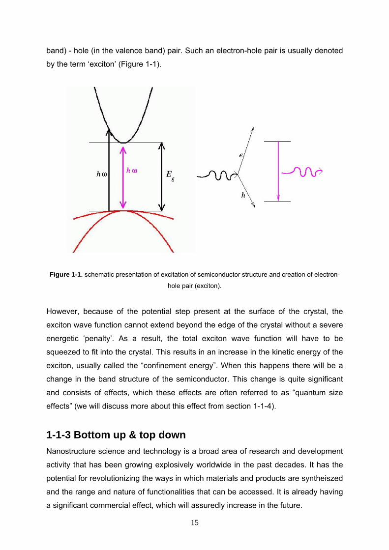
band) - hole (in the valence band) pair. Such an electron-hole pair is usually denoted
by the term ‘exciton’ (Figure 1-1).
Figure 1-1. schematic presentation of excitation of semiconductor structure and creation of electron-
hole pair (exciton).
However, because of the potential step present at the surface of the crystal, the
exciton wave function cannot extend beyond the edge of the crystal without a severe
energetic ‘penalty’. As a result, the total exciton wave function will have to be
squeezed to fit into the crystal. This results in an increase in the kinetic energy of the
exciton, usually called the “confinement energy”. When this happens there will be a
change in the band structure of the semiconductor. This change is quite significant
and consists of effects, which these effects are often referred to as “quantum size
effects” (we will discuss more about this effect from section 1-1-4).
1-1-3 Bottom up & top down Nanostructure science and technology is a broad area of research and development
activity that has been growing explosively worldwide in the past decades. It has the
potential for revolutionizing the ways in which materials and products are syntheiszed
and the range and nature of functionalities that can be accessed. It is already having
a significant commercial effect, which will assuredly increase in the future.
15
Of particular interest to materials scientists is the fact that nanostructure materials
have higher surface areas than do normal materials. The effect of nanostructure on
the properties of high surface area materials is an area of increasing importance to
understanding, synthesing, and improving materials for wide applications.
Scientists and engineers typically have approached the synthesis and creating of
high surface area nanostructures from one of two directions:
1. The “bottom up” approach in which the nanostructures are built up from individual
atoms or molecules or according other definition the “bottom-up” approach first forms
the nanostructured building blocks and then assembles them into the final material.
This is the basis of “cluster science” as well as crystal materials synthesis, usually via
chemical ways. Both high surface area particles and micro- and mesoporous
crystalline materials with high void volume (pore volume) are included in this “bottom
up” approach. An example of this approach is the formation of powder components
from aerosol techniques and then the compaction of the components into the final
material (5). These techniques have been used extensively in the formation of
structural composite materials.
2. The “top down” approach in which nanostructures are created from breaking up
bulk materials or other definition says one “top-down” approach begins with a suitable
starting material and then “sculpts” the functionality from the material. This technique
is similar to the approach used by the semiconductor field in forming devices out of
an electronic substrate (silicon), utilizing pattern formation (such as electron beam
lithography) and pattern transfer processes (such as reactive ion etching) that have
the requisite spatial resolution to achieve creation of structures at the nanoscale.
Another example of top-down approach is “ball-milling,” the formation of
nanostructure building blocks from controlled, mechanical attrition of the bulk starting
material. Those nano building blocks are then subsequently assembled into a new
bulk material (6,7).
1-1-4 A brief review of quantum dots Nanoparticles are made out of metallic, semiconductor or insulating materials that are
much smaller than the wavelength of light. In the last decades there has been much
interest on nanoparticles made out of semiconductor materials, especially on II-VI
semiconductor types, e.g. CdSe, CdTe, CdS, ZnS, etc., and III-V, e.g. GaAs (8-10).
16
That was the first time that researcher became aware of the quantum confinement
effects produced by the change of bulk semiconductor electronic properties with
decreasing size. This effect occurs when the nanostructures themselves become
smaller than a fundamental scale intrinsic to the substance. It was later proven that
the exciton Bohr radius could determine this intrinsic scale. Since this effect is
determined by hydrogen atom model of the exciton Bohr radius they were named
‘quantum dots’ or ‘artificial atoms’. Quantum dots belong to the category of zero
dimensional structures. They are made of few thousand atoms that keep the
structural features of the bulk solid but particularly different electronic properties as a
function of their size.
With the advent of modern synthesis techniques, scientists have acquired the ability
to create structures with dimensions on the nanometre scale. One major point in
these developments has been the reduction of the dimension of particles from three-
dimensional bulk systems to two-dimensional, to one-dimensional, and finally to zero-
dimensional systems. When the size of all these particles becomes comparable with
the de Broglie wavelength, a consequence of the wave nature of electrons, electrons
confined in these particles shows quantum effects.
The new electronic and optical properties of these reduced-dimensional particles,
which can be controlled to a certain extent t, make these particles promising
candidates for a variety of future applications that include improved semiconductor
lasers and microelectronics. Quantum dots represent the ultimate reduction in the
dimensionality of a semiconductor system. In these systems, electrons are confined
in all directions. Therefore they have no kinetic energy (except the ubiquitous zero-
point energy) and as a result they occupy spectrally sharp energy levels like those
found in atoms.
These zero-dimensional quantum confined particles are useful for considering the
fundamental concepts of nanostructures as well as for its potential to act at the level
of a single electron, certainly the ultimate limit for an electronic device. With a good
knowledge of their electrical and optical properties, scientists have now focused their
attention on devices based on quantum dots. Some of the best examples are QD
photodetectors, QD lasers and QD memory devices. Quantum dots have also found
applications in fluorescence markers, exciton storage, a step toward smart pixels,
quantum computing and quantum cryptography (11-13).
17
1-1-5 From three- to zero-dimensional systems There are different sources available in the literature on the evolution from three to
zero-dimensional systems (14,15). These are schematically shown in figure 1-2. The
energy of a free electron in the bulk material is well known. It is a parabolic function
of the three-dimensional wave vector. In a two-dimensional system, such as a
quantum well, electron motion is confined in one dimension (say the z-direction).
The electron motion is still free in the x; y plane and the energy is a parabolic function
of the two-dimensional wave vector. In the z-direction, electron motion is quantized
into discrete subbands Ei. Further confinement (lateral) of the electron motion leads
to one-dimensional (quantum wire) and zero-dimensional (quantum dot) systems. In
the case of a quantum dot, the energy Einm is totally discrete, because just like in
atoms there is no free motion with continuous energy dispersion in any direction, i.e.
electrons have no kinetic energy due to their motion (there is, of course the zero-
point energy).
The dimensionality of confinement significantly affects the electronic and optical
properties of low-dimensional systems which in turn can be directly attributed to the
influence of dimensionality on the density of states (DOS) (16).
18
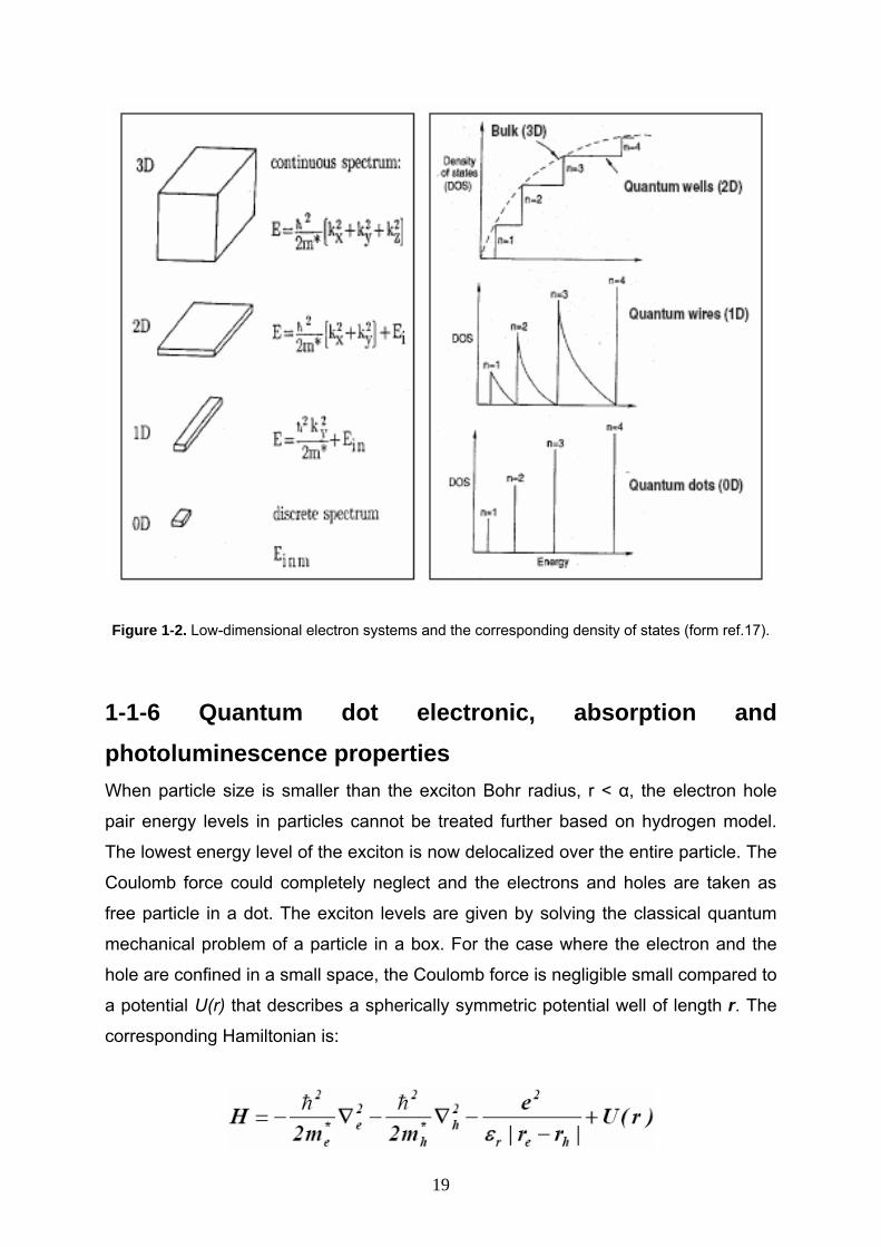
Figure 1-2. Low-dimensional electron systems and the corresponding density of states (form ref.17).
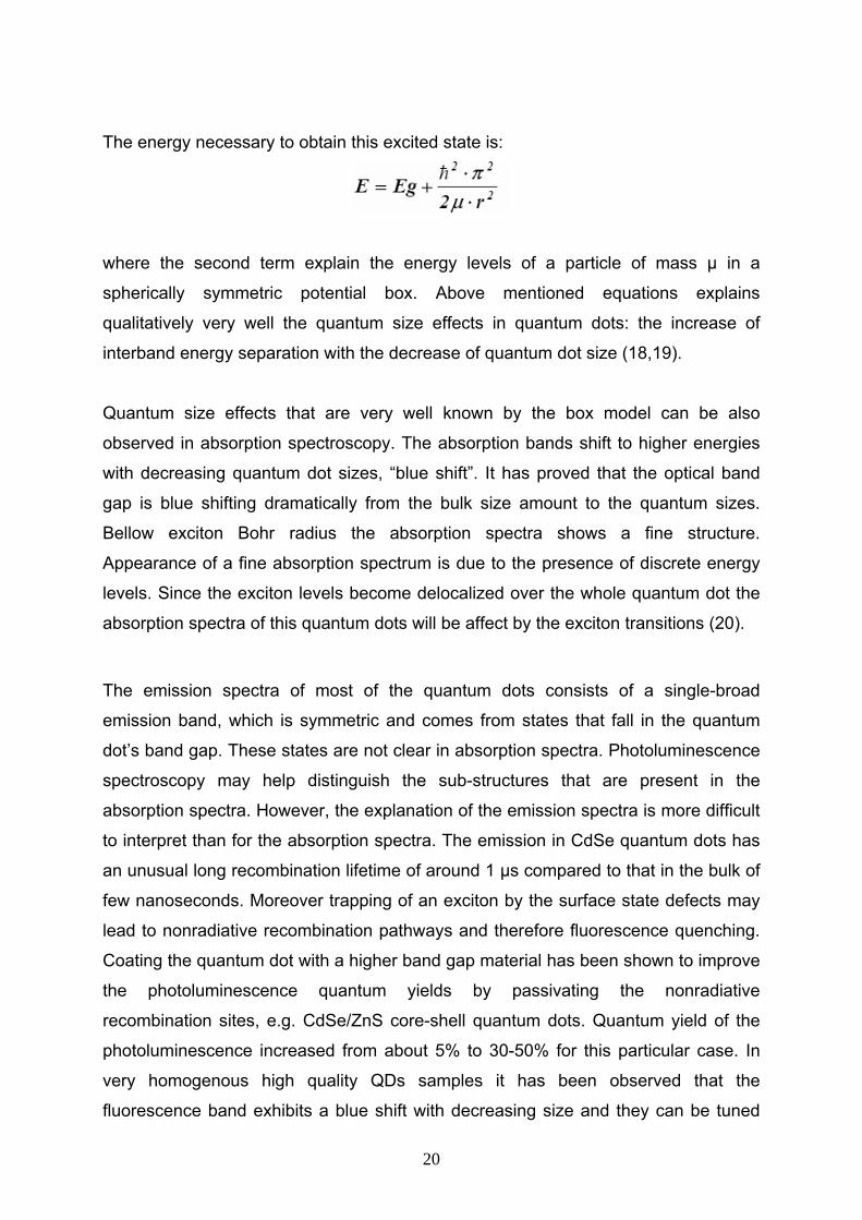
1-1-6 Quantum dot electronic, absorption and photoluminescence properties When particle size is smaller than the exciton Bohr radius, r < α, the electron hole
pair energy levels in particles cannot be treated further based on hydrogen model.
The lowest energy level of the exciton is now delocalized over the entire particle. The
Coulomb force could completely neglect and the electrons and holes are taken as
free particle in a dot. The exciton levels are given by solving the classical quantum
mechanical problem of a particle in a box. For the case where the electron and the
hole are confined in a small space, the Coulomb force is negligible small compared to
a potential U(r) that describes a spherically symmetric potential well of length r. The
corresponding Hamiltonian is:
19
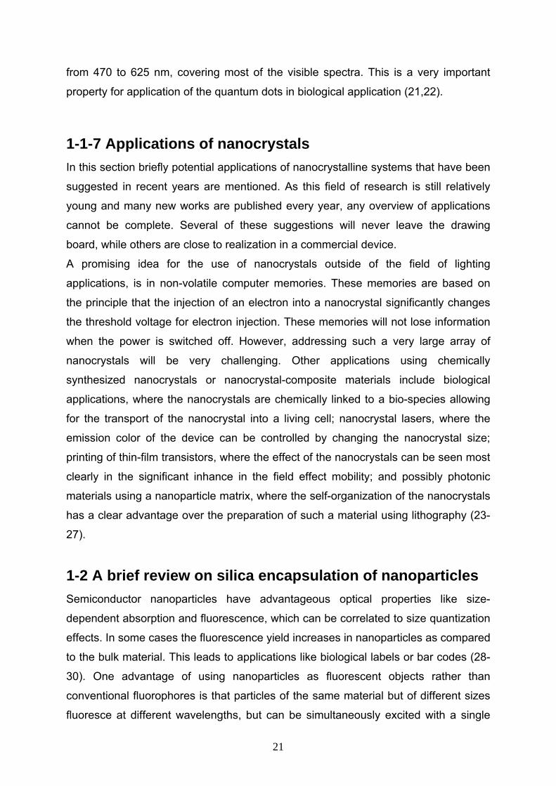
The energy necessary to obtain this excited state is:
where the second term explain the energy levels of a particle of mass µ in a
spherically symmetric potential box. Above mentioned equations explains
qualitatively very well the quantum size effects in quantum dots: the increase of
interband energy separation with the decrease of quantum dot size (18,19).
Quantum size effects that are very well known by the box model can be also
observed in absorption spectroscopy. The absorption bands shift to higher energies
with decreasing quantum dot sizes, “blue shift”. It has proved that the optical band
gap is blue shifting dramatically from the bulk size amount to the quantum sizes.
Bellow exciton Bohr radius the absorption spectra shows a fine structure.
Appearance of a fine absorption spectrum is due to the presence of discrete energy
levels. Since the exciton levels become delocalized over the whole quantum dot the
absorption spectra of this quantum dots will be affect by the exciton transitions (20).
The emission spectra of most of the quantum dots consists of a single-broad
emission band, which is symmetric and comes from states that fall in the quantum
dot’s band gap. These states are not clear in absorption spectra. Photoluminescence
spectroscopy may help distinguish the sub-structures that are present in the
absorption spectra. However, the explanation of the emission spectra is more difficult
to interpret than for the absorption spectra. The emission in CdSe quantum dots has
an unusual long recombination lifetime of around 1 µs compared to that in the bulk of
few nanoseconds. Moreover trapping of an exciton by the surface state defects may
lead to nonradiative recombination pathways and therefore fluorescence quenching.
Coating the quantum dot with a higher band gap material has been shown to improve
the photoluminescence quantum yields by passivating the nonradiative
recombination sites, e.g. CdSe/ZnS core-shell quantum dots. Quantum yield of the
photoluminescence increased from about 5% to 30-50% for this particular case. In
very homogenous high quality QDs samples it has been observed that the
fluorescence band exhibits a blue shift with decreasing size and they can be tuned
20
from 470 to 625 nm, covering most of the visible spectra. This is a very important
property for application of the quantum dots in biological application (21,22).
1-1-7 Applications of nanocrystals In this section briefly potential applications of nanocrystalline systems that have been
suggested in recent years are mentioned. As this field of research is still relatively
young and many new works are published every year, any overview of applications
cannot be complete. Several of these suggestions will never leave the drawing
board, while others are close to realization in a commercial device.
A promising idea for the use of nanocrystals outside of the field of lighting
applications, is in non-volatile computer memories. These memories are based on
the principle that the injection of an electron into a nanocrystal significantly changes
the threshold voltage for electron injection. These memories will not lose information
when the power is switched off. However, addressing such a very large array of
nanocrystals will be very challenging. Other applications using chemically
synthesized nanocrystals or nanocrystal-composite materials include biological
applications, where the nanocrystals are chemically linked to a bio-species allowing
for the transport of the nanocrystal into a living cell; nanocrystal lasers, where the
emission color of the device can be controlled by changing the nanocrystal size;
printing of thin-film transistors, where the effect of the nanocrystals can be seen most
clearly in the significant inhance in the field effect mobility; and possibly photonic
materials using a nanoparticle matrix, where the self-organization of the nanocrystals
has a clear advantage over the preparation of such a material using lithography (23-
27).
1-2 A brief review on silica encapsulation of nanoparticles Semiconductor nanoparticles have advantageous optical properties like size-
dependent absorption and fluorescence, which can be correlated to size quantization
effects. In some cases the fluorescence yield increases in nanoparticles as compared
to the bulk material. This leads to applications like biological labels or bar codes (28-
30). One advantage of using nanoparticles as fluorescent objects rather than
conventional fluorophores is that particles of the same material but of different sizes
fluoresce at different wavelengths, but can be simultaneously excited with a single
21
wavelength in the UV range, also reducing the photobleaching. The brilliant optical
properties of QDs offer the possibility of using them to tag biomolecules in
ultrasensitive biological detection based on optical coding technology. However, QDs
themselves are not water dispersible, not biocompatible and chemically stable, and
do not have functional groups for conjugation with biomolecules.
Quantum dots contain toxic components, such as cadmium (from cadmium
chalcogenide-based quantum dots) or lead (from lead chalcogenide-based quantum
dots). Cd2+ and Pb2+ could be released from quantum dots and then kill the cells (31-
33).
In order to overcome these drawbacks nanoparticles can be either coated with a
large-band-gap semiconductor material, a polymer, or with insulators like silica,
titania, etc., leading to core-shell particles (34, 35). Therefore further development of
applications of semiconductor NCs requires means for incorporating them in various
matrixes. On one hand, this would provide protection and compatibility for the NCs
with various environments, and on the other hand, this would impart specific
properties of the NCs to the carrier matrix.
1-2-1 Core-shell nanocomposites In recent decades, advanced materials stems from core-shell composite particles are
of extensive scientific and technological interests because of the ability to fine tune
their properties. The structure, size, and composition of these particles can be easily
altered in a controllable way to tailor their magnetic, optical, mechanical, thermal,
electrical, electrooptical, and catalytic properties. Core-shell materials consist of a
core structural domain covered by a shell domain. The core and shell may be
composed of a variety of materials including polymers, inorganic solids, and metals.
From other point they have properties which may different from the core or of the
shell material.
The creation of core-shell particles is attracting a great interest because of the variety
of applicability of these colloidal particles; e.g., as building blocks for photonic
crystals, in multi-enzyme biocatalysis, and in drug delivery. Also they are interesting
from a fundamental and scientific viewpoint. They can be utilized as model systems
to investigate factors which governing colloidal interactions and stabilization and to
reach valuable information on the properties of concentrated dispersions.
22
Coating is one of the methods that can be used for the formation of core-shell
nanoparticles. Up to now, many routes have been developed to fabricate core-shell
materials such as sol-gel process, layer-by-layer technique, templatedirected self-
assembly, and encapsulation of nanoparticles by in situ polymerization (36-39).
1-2-2 Advantages of core-shell on bare nanoparticles However, it is a common experience that the nanoparticle surfaces, which are the
smaller the particles are, strained, have dangling bonds, are susceptible to oxidation,
coalescence, or other instabilities. Also the quantum dots which synthesized in
organic solvents are not dispersible in water (biomedical applications require high-
quality water dispersible quantum dots). Hence a challenge is how to make the high-
quality hydrophobic quantum dots dispersible in water and also active in bioconjugate
reactions. Therefore materials are coated for a number of reasons: Coatings can
make a particle biocompatible, increase thermal, mechanical, or chemical stability,
increase durability, or lifetime, decrease friction or inhibit corrosion, otherwise change
the overall physicochemical and biological properties of the material. The coating
prevents the aggregation in liquid, as compared to their bare particles and provides a
biofunctional surface for modification and subsequent bioconjugation.
A common technique for stabilizing nanoparticles is the use of surface active agents
or macromolecular materials that are adsorbed to particle surface to form a physical
barrier against other penetrating particles.
Typically, the quantum dots synthesized in organic solvents have hydrophobic
surface ligands such as trioctylphosphine oxide (TOPO), trioctylphosphine (TOP),
tetradecylphosphonic acid (TDPA) or oleic acid (40-42). These hydrophobic ligands
could be replaced by some water dispersible bifunctional molecules. Examples of
some water dispersible bifunctional species used are mercaptocarbonic acids, 2-
aminoethanethiol, dithiothreitol, dihydrolipoic acid, oligomeric phosphines, peptides,
and cross-linked dendrons (43-46).
However, ligand exchange can alters the chemical and physical states of the
quantum dot surface atoms and in most cases considerably decreases the quantum
efficiency of the quantum dots; for example thiol-based molecules may form
disulfides during time and come off from the quantum dot surface and finally the
quantum dots aggregate and precipitate out of water; For example Chan and Nie
used mercaptoacetic acid as a coupling reagent with ZnS capped CdSe (CdSe/ZnS)
23
quantum dots. It was shown that this surface modification of quantum dots does not
ensure persistent bonding, leading to slow desorption of mercaptoacetic acid
molecules from the surface of quantum dots, resulting in poor stability of quantum
dots in water. The other water-soluble bifunctional molecules are expensive and
instable (47-51).
To overcome this problem coating of the particles with inert silica shells has been
used as a stabilizing technique, which a thin silica layer was covalently bound on the
surface of QDs.
1-2-3 Advantages of silica shell (colloidal stability, cytotoxicity, etc) The formation of silica particles has been the subject of extensive investigations for
years because of their wide commercial applications and interesting structural
properties. Several methods of synthesis were introduced and various techniques
were applied to characterize the silica particles. These surface coatings allow manipulation of the interaction potential and make it
possible to disperse colloids in a wide range of solvents from very polar to apolar.
There are several advantages for using silica shells instead of other stabilizers. Silica
is chemically inert and optically transparent (so that chemical reactions can be
monitored spectroscopically) and does not affect redox reactions at the core surface,
except by physical blocking of the surface. Most obviously, the shell prevents
coagulation during chemical reactions, and concentrated dispersions of nanosized
semiconducting, magnetic, or metallic materials can be created (52, 53).
The unusual properties of silica, especially in aqueous media provide the particles
with a very much enhanced colloidal stability, so they remain stable over a much
wider range of solution conditions, such as ionic strength, temperature, solvent
polarity, etc. for example silica-coated particles can endure large variations in pH,
prevent coalescing also the colloids are stable at higher temperatures which is
important for applications involving laser irradiation of nanoparticles. Additionally, the
ability to control the thickness of the silica shell implies that the separation between
neighboring particles can be tuned, so that the collective behavior of the particles
within the nanostructure can be tailored (54, 55).
Another advantage for the silica coating is that the colloid chemistry of silica is well
known and many possibilities for surface modification are available (this surface is
24
often terminated by a silanol group that can react with various coupling agents to
covalently attach specific ligands to the surfaces of silica coated nanoparticles) which
can be obtained by modifying the hydroxyls on the silica surface with amines, thiols,
carboxyls, and methacrylate. This modification can facilitate the incorporation of
these particles into nonpolar solvents, glasses, and polymeric matrixes. Such a
possibility will open the wide door to the design and synthesis of composites that can
be used to deliver specific ligands to target organs via the antibody-antigen
recognition (56-58).
From biological point silica coated nanoparticles possess several advantages over
other particles when used as biomarkers: (1) Silica coated nanoparticles are easy to
centrifuge during preparation, functionalization, and other treatment processes in
solution because of higher density of silica. (2) Bare particles are generally more
hydrophobic than silica particles and, therefore, tend to agglomerate in aqueous
environment. The presence of silanol groups on the silica surface makes silica
coated nanoparticles more hydrophilic, and therefore, it is easy to disperse them in
aqueous medium. (3) Dye-doped latex particles swell in organic solvents, resulting in
dye molecule leakage. Latex particles are also soluble in organic solvents. These
problems do not exist in silica coated nanoparticles, because silica is inert in both
aqueous and nonaqueous solvents. (4) Unlike polymeric layers, it is not subject to
microbial attack and there is no porosity change occurring in these particles with the
pH variation. (5) Studies show direct, cytotoxicity of water-soluble CdSe and
CdSe/ZnS quantum dots, because Cd2+ is released from the nanoparticles which is
highly due to poor purifications or simple surface cappings/coatings. Quantum dots
coated by simple molecules, such as mercaptoacetic acid, mercaptopropionic acid,
11- mercaptoundecanoic acid, 2-aminoethanethiol, are more toxic than the ones
coated with silica layer. The silica layer is different from the amphiphilic polymer layer
or small molecular ligands; it can be very thick and therefore reduce the possible
leaking of toxic cadmium or lead under physiological environments. In addition to the
extracellular cytotoxicity studies, it has found that quantum dots could enter the cells
through endocytosis, and causes the cell death. In silica coated particles because of
a comparatively low size and high hydrophilicity, presumably, these nanoparticles
can be exhausted from the organism through the kidneys without accumulation into
different tissues and the risk for long-term side-effects (59-61).
25
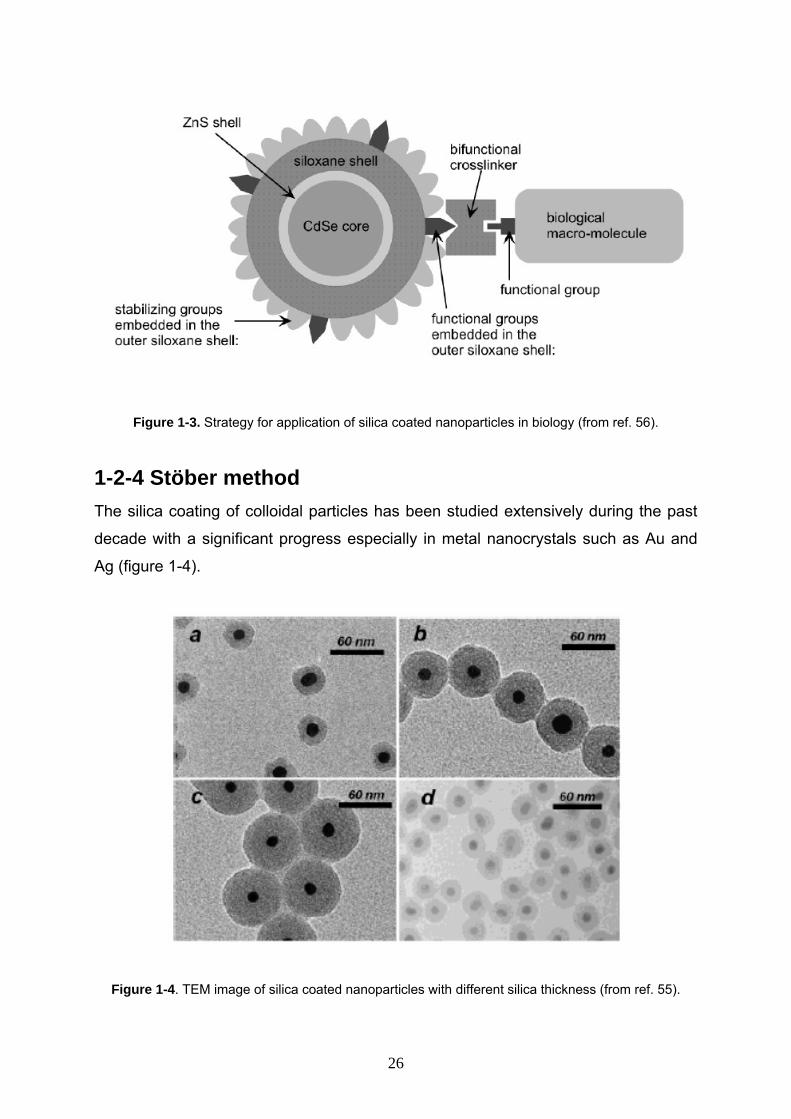
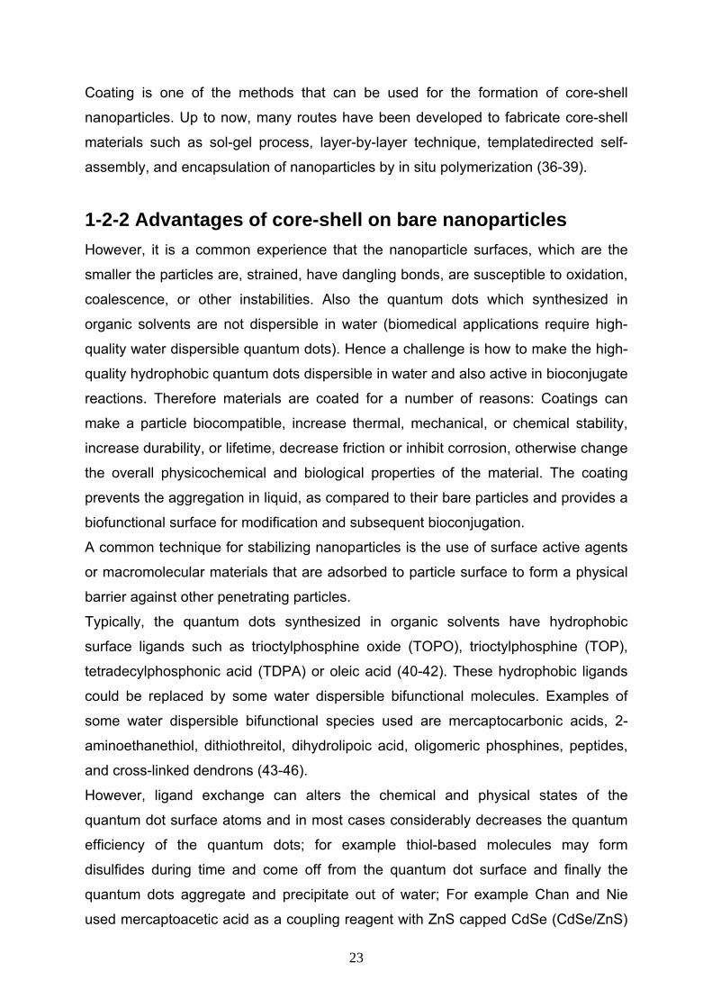
Figure 1-3. Strategy for application of silica coated nanoparticles in biology (from ref. 56).
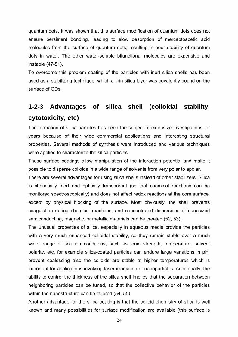
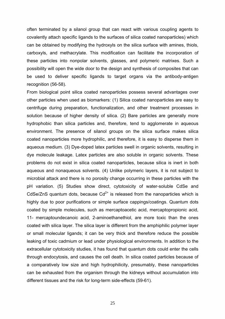
1-2-4 Stöber method The silica coating of colloidal particles has been studied extensively during the past
decade with a significant progress especially in metal nanocrystals such as Au and
Ag (figure 1-4).
Figure 1-4. TEM image of silica coated nanoparticles with different silica thickness (from ref. 55).
26
Preparation of silica particles of desired properties was first demonstrated by Stöber
et al. in 1968 (62). In this pioneering work on the production of silica, Stöber et al
developed a process capable of forming controlled silica particles in the range from
500 nm to 2 µm. A typical reaction mixture contained tetraethoxysilane (TEOS) as
silica precursor, water, ethanol and ammonia. The silica particles produced had a
narrow size distribution and could be controlled by controlling the solution pH,
composition of reactants and temperature. The process was typically carried out at
room temperature and at higher pH (~ 10). The Stöber route is very popular and
currently many industrial manufacturing processes are based on this process.
Since the hydrolysis of TEOS with water is very slow, either an acid or ammonia is
used to serve as a catalyst. The former encourages the growth of gel structures,
while the latter is a morphological catalyst producing spherical particles.
Stoichiometrically, the reaction proceeds as:
Si(OC2H5)4 + 2H2O ↔ SiO2 + 4C2H5OH
The reaction is actually a hydrolysis:
Si(OC2H5)4 + 4H2O ↔ Si(OH)4 + 4C2H5OH
followed by a condensation step:
Si(OH)4 ↔ SiO2 + 2H2O
Polymerization of silicic acid may occur in two ways. In acidic solutions, chain-like or
open-branched polymers are initially produced by the condensation of silane groups.
Polymerization in alkaline solutions take place by internal condensation and cross-
linking to give particles in which consists of four silicon-oxygen bonds and the
hydroxyl groups are attached to the surface of the particles only (63-65).
Many investigations have been done to the understanding of the silica growth
mechanism. Among them, Lamer et al (66) developed a solute molecular addition
model for silicon dioxide particle growth in a sol-precipitation. According to this
model, the SiO2 produced by the reaction in the solution is transferred from the bulk
to the particle and then integrated on the particle surface, thereby causing particle
growth. To mathematically predict the particle size produced in the sol-precipitation,
Matsuokas et al (67) introduced the molecular addition model. In this model, it is
assumed that during the initial stage of the precipitation, the particle is nucleated with
the product of the hydrolysis and condensation of tetraethylorthosilicate (TEOS). A
diffusion growth model was proposed by Chen et al. (68) for SiO2 growth in a sol
precipitation with TEOS and is similar to the molecular addition model. The principle
27
of their model is the molecular diffusion of silicon dioxide for particle growth. As a
result, the formation of a secondary particle depends on the balance between the
production rate of silicon dioxide by the reaction on one hand and the depletion rate
of silicon dioxide by particle growth on the other. A mathematical model of primary
particle aggregation was developed by Bogush et al. (69) to describe the silicon
dioxide particle growth in a sol-precipitation. According to this model, when the
synthesis of silicon dioxide particles starts with TEOS, the supersaturation of soluble
product in the solution is initially created by the hydrolysis and condensation
reactions. When the supersaturation rises above a critical level, a huge number of
primary particles of silicon dioxide is suddenly produced by high nucleation rate in the
supersaturation solution and then is quickly aggregated to form large stable particles.
After that, the stable particles grow by aggregation of primary particles.
Major disadvantages of the Stöber method for silica encapsulation are the high
requirements on purity of the reactants, the difficulty and multiplicity of the
preparation steps, and the fact that nanoparticles with nonpolar ligands cannot be
coated easily or directly.
1-2-5 Modified stöber method (pre-treatment with Silane coupling agents) However, silica deposition on pure metal particles is more complicated because of
the lack of OH groups on the metal surface. Therefore, it is necessary to use a primer
to make the surface “vitreophilic”. This chemistry has been used for noble metals
which are chemically very stable. For inert metal like gold or silver particles (There
has been much interest in the synthesis of this core-shell nanoparticles for diverse
applications, which include the templating of material syntheses for molecular
confinement and optoelectronics), surface chemical derivatization is often undertaken
prior to the formation of inorganic layers. In a series of studies Liz-Marzán and co-
workers (70-71) have extensively studied metal–silica core–shell particles prepared
by a procedure in which the use of a surface primer (a silane coupling agent) was
necessary to provide the surface with silanol anchor groups. Thereby rendering the
gold surface vitreophilic via its complexation with the amine groups of the silane,
receptive toward silica monomers or oligomers. This permits the deposition of thin,
28
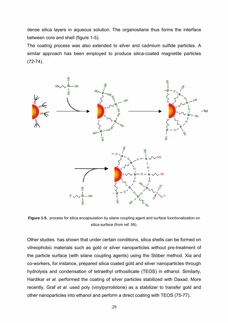
dense silica layers in aqueous solution. The organosilane thus forms the interface
between core and shell (figure 1-5).
The coating process was also extended to silver and cadmium sulfide particles. A
similar approach has been employed to produce silica-coated magnetite particles
(72-74).
Figure 1-5. process for silica encapsulation by silane coupling agent and surface functionalization on
silica surface (from ref. 56).
Other studies has shown that under certain conditions, silica shells can be formed on
vitreophobic materials such as gold or silver nanoparticles without pre-treatment of
the particle surface (with silane coupling agents) using the Stöber method. Xia and
co-workers, for instance, prepared silica coated gold and silver nanoparticles through
hydrolysis and condensation of tetraethyl orthosilicate (TEOS) in ethanol. Similarly,
Hardikar et al. performed the coating of silver particles stabilized with Daxad. More
recently, Graf et al. used poly (vinylpyrrolidone) as a stabilizer to transfer gold and
other nanoparticles into ethanol and perform a direct coating with TEOS (75-77).
29
Main disadvantage of using silane coupling agents for silica encapsulation are: high
sensitivity of this reagents to oxygen and humidity, difficulty to manage system to
have a silica shell instead of gelated or polymeric products, etc.
1-2-6 Microemulsion method Materials with different chemical compositions were synthesized within reverse
micelles. Applications of the produced materials by using reverse micelles are
widespread in paints and surface coatings, catalysis, separation media, drug delivery
systems, high frequency electronic components, etc (78-80).
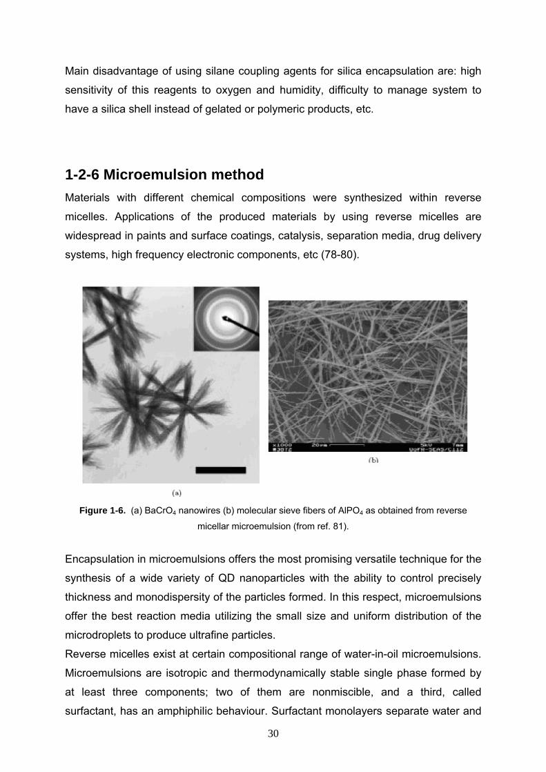
Figure 1-6. (a) BaCrO4 nanowires (b) molecular sieve fibers of AlPO4 as obtained from reverse
micellar microemulsion (from ref. 81).
Encapsulation in microemulsions offers the most promising versatile technique for the
synthesis of a wide variety of QD nanoparticles with the ability to control precisely
thickness and monodispersity of the particles formed. In this respect, microemulsions
offer the best reaction media utilizing the small size and uniform distribution of the
microdroplets to produce ultrafine particles.
Reverse micelles exist at certain compositional range of water-in-oil microemulsions.
Microemulsions are isotropic and thermodynamically stable single phase formed by
at least three components; two of them are nonmiscible, and a third, called
surfactant, has an amphiphilic behaviour. Surfactant monolayers separate water and
30
oil domains and hence reduce the unfavourable oil–water contact. In contrast to
macroscopic emulsions which are thermodynamically unstable, nanosized
microemulsion droplets are formed spontaneously are thermodynamically stable. The
surfactant molecule lowers the interfacial tension between water and oil resulting in
the formation of a transparent solution.
Reverse micellar synthesis of materials belongs to the class of wet materials
synthesis procedures, and exhibits, in general, all the advantages that usually
accompany other wet approaches to materials synthesis. Particles prepared by the
reverse microemulsion method show good promise in size control and further
miniaturization.
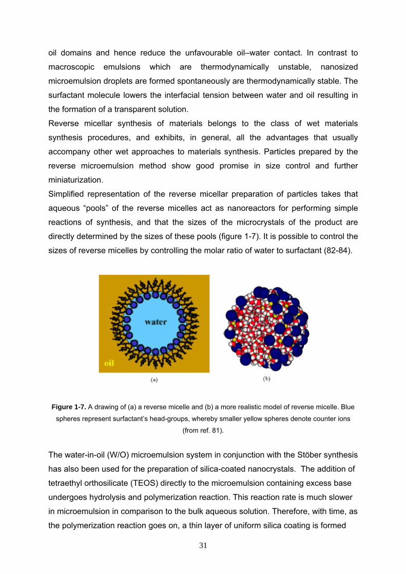
Simplified representation of the reverse micellar preparation of particles takes that
aqueous “pools” of the reverse micelles act as nanoreactors for performing simple
reactions of synthesis, and that the sizes of the microcrystals of the product are
directly determined by the sizes of these pools (figure 1-7). It is possible to control the
sizes of reverse micelles by controlling the molar ratio of water to surfactant (82-84).
Figure 1-7. A drawing of (a) a reverse micelle and (b) a more realistic model of reverse micelle. Blue
spheres represent surfactant’s head-groups, whereby smaller yellow spheres denote counter ions
(from ref. 81).
The water-in-oil (W/O) microemulsion system in conjunction with the Stöber synthesis
has also been used for the preparation of silica-coated nanocrystals. The addition of
tetraethyl orthosilicate (TEOS) directly to the microemulsion containing excess base
undergoes hydrolysis and polymerization reaction. This reaction rate is much slower
in microemulsion in comparison to the bulk aqueous solution. Therefore, with time, as
the polymerization reaction goes on, a thin layer of uniform silica coating is formed
31
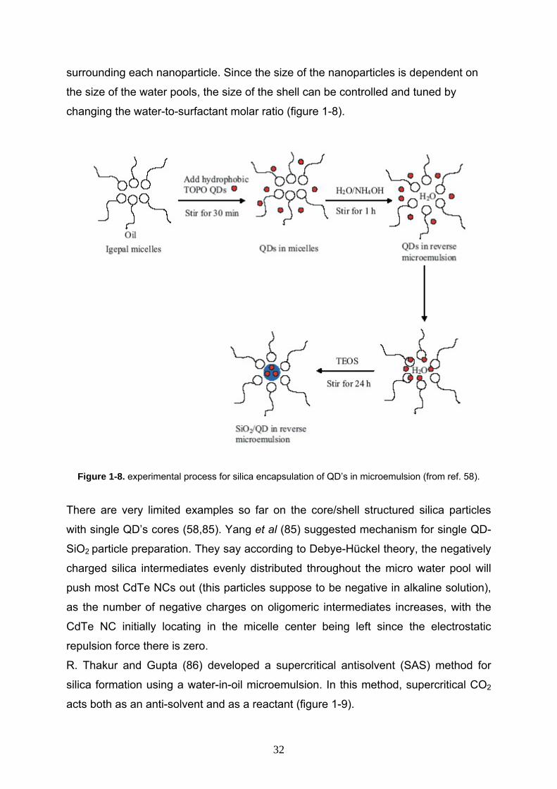
surrounding each nanoparticle. Since the size of the nanoparticles is dependent on
the size of the water pools, the size of the shell can be controlled and tuned by
changing the water-to-surfactant molar ratio (figure 1-8).
Figure 1-8. experimental process for silica encapsulation of QD’s in microemulsion (from ref. 58).
There are very limited examples so far on the core/shell structured silica particles
with single QD’s cores (58,85). Yang et al (85) suggested mechanism for single QD-
SiO2 particle preparation. They say according to Debye-Hückel theory, the negatively
charged silica intermediates evenly distributed throughout the micro water pool will
push most CdTe NCs out (this particles suppose to be negative in alkaline solution),
as the number of negative charges on oligomeric intermediates increases, with the
CdTe NC initially locating in the micelle center being left since the electrostatic
repulsion force there is zero.
R. Thakur and Gupta (86) developed a supercritical antisolvent (SAS) method for
silica formation using a water-in-oil microemulsion. In this method, supercritical CO2
acts both as an anti-solvent and as a reactant (figure 1-9).
32

Figure 1-9. Schematic of the apparatus for silica coating using supercritical CO2 (from ref. 86).
The preparation of nanoparticles within microemulsions has been shown to be a
convenient route towards monodisperse particles of controllable size. This method
exploits two useful properties: the capacity to dissolve reactants in the water pool and
the constant exchange of the aqueous phase among micelles. Thus, by mixing
microemulsions containing different reactants, it is possible to perform chemical
reactions within reverse micelle water pools by using them as a nanoreactor.
1-2-7 Surface derivatization on silica shell Silica coated particles are biocompatible but it needs more functionalization.
Functional organosilicone molecules containing –NH2 or –SH, can incorporated into
the silica shell and provide surface functionalities for biomedical and other
applications.
Despite the range of methodologies available, the variety of functional groups that
can be incorporated into the silica framework is often limited.
The silica surface consists of two types of functional groups, siloxane (Si–O–Si) and
silanol (Si–OH). Thus, silica modification can occur via the reaction of a particular
molecule which either the siloxane or silanol functions (87-89).
Chlorination of the silica surface followed by subsequent reaction with Grignard
reagents can be used to form silicon-carbon bonds (figure 1-10).
33
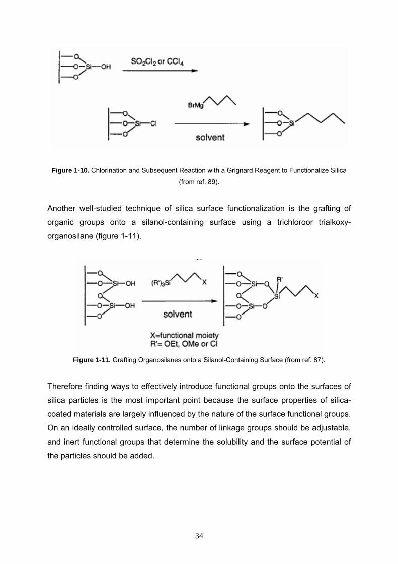
Figure 1-10. Chlorination and Subsequent Reaction with a Grignard Reagent to Functionalize Silica
(from ref. 89).
Another well-studied technique of silica surface functionalization is the grafting of
organic groups onto a silanol-containing surface using a trichloroor trialkoxy-
organosilane (figure 1-11).
Figure 1-11. Grafting Organosilanes onto a Silanol-Containing Surface (from ref. 87).
Therefore finding ways to effectively introduce functional groups onto the surfaces of
silica particles is the most important point because the surface properties of silica-
coated materials are largely influenced by the nature of the surface functional groups.
On an ideally controlled surface, the number of linkage groups should be adjustable,
and inert functional groups that determine the solubility and the surface potential of
the particles should be added.
34
References 1- K.M. Ryan, A. Mastroianni, K.A. Stancil, H.T. Liu, A.P. Alivisatos, Nano Lett. 2006,
6, 1479.
2- J. Pacifico, J. Jasieniak, D. E. Gomez, P. Mulvaney, Small. 2006, 2, 199.
3- I.V. Kityk, J. Ebothé, Q. Liu, Z. Sun, J. Fang, Nanotechnology 2006, 17, 1871.
4- G. Jaeckel, Z. Tech. Phys. 1926, 6, 301.
5- M.K. Wu, R.S. Windeler, C.K. Steiner, T. Bors, and S.K. Friedlander., Aerosol Sci.
Technol. 1993, 19, 527.
6- D.L. Leslie-Pelecky, and R.D. Reike. Chem. Mater. 1996, 8,1770.
7- C.C. Koch, Annual Review of Mater. Sci. 1989, 19,121.
8- C. Sonnichsen, A. P. Alivisatos, Nano Lett. 2005, 5, 301.
9- L. M. Liz-Marzan, P. Mulvaney, J. Phys. Chem. B. 2003, 107, 7312.
10- Z. Liu, D. Zhang, S. Han, C. Li, B. Lei, W. Lu, J. Fang, C. Zhou, J. Am. Chem.
Soc. 2005 , 127,6.
11- P. Yang, C. L. Li, N. Murase, Langmuir. 2005, 21, 8913.
12- J. Riegler, P. Nick, U. Kielmann, T. Nann, J. Nanosci. Nanotechno. 2003, 3, 380.
13- H. H. Yang, S. Q. Zhang, X. L. Chen, Z. X. Zhuang, J. G. Xu, X. R. Wang, Anal.
Chem. 2005, 77,354.
14- L. J. Challis, Contemporary Phys.1992, 33, 111.
15- P. A. Maksym and T. Charkraborty, Phys. rev. Lett., 1990, 65, 108.
16- T. Charkraborty, Comments Condens. Matter Phys., 1992, 16, 35.
17- T. Charkraborty and V. M. Apalkov, Adv. Phys., 2003, 52, 455.
18- Y. Z. Hu, M. Lindberg, S.W. Koch, Phys. Rev. B., 1990, 42,1713.
19- N. Chestnoy, T.D. Harris, R. Hull, L.E. Brus, J. Phys.Chem.,1986, 90, 3393.
20- C. B. Murray, D.J. Norris, M.G. Bawendi, J. Am. Chem. Soc., 1993, 115, 8706.
21- M. Lee, J.K. Kuno, B.O. Dabbousi, F.V. Mikulec, M.G. Bawendi, J. Chem. Phys.,
1997, 106, 9869.
22- B.O. Dabbousi, J. Rodriguez-Viejo, F.V. Mikulec, J.R. Heine, H. Mattoussi, R.
Ober, J. Phys. Chem. B., 1997, 101, 9463.
23- S. Tiwari, F. Rana, H. Hanafi, A. Hartstein and E. F. Crabb´e, Appl. Phys. Lett.
1996, 68, 1377.
24- M. Bruchez Jr., M. Moronne, P. Gin, S.Weiss and A. P. Alivisatos, Science 1998,
281, 2013.
25- V. I. Klimov, A. A. Mikhailovsky, S. Xu, A. Malko, J. A. Holligsworth, C. A.
35
Leatherdale, H. J. Eisler and M. G. Bawendi, Science 2000, 290, 314.
26- B. A. Ridley, B. Nivi and J. M. Jacobson, Science 1999, 286, 746.
27- K. P. Velikov, C. G. Christova, R. P. A. Dullens, and A. van Blaaderen, Science
2002, 296, 106.
28- C. Sonnichsen, A. P. Alivisatos, Nano Lett., 2005, 5, 301.
29- L. M. Liz-Marzan, P. Mulvaney, J. Phys. Chem. B. 2003, 107, 7312.
30- Z. Liu, D. Zhang, S. Han, C. Li, B. Lei, W. Lu, J. Fang, C. Zhou, J. Am. Chem.
Soc. 2005 , 127,6.
31- W. C. W. Chan, S. M. Nie, Science, 1998, 281, 2016.
32- C. Y. Zhang, H. Ma, S. M. Nie, Y. Ding, L. Jin, D. Y. Chen, Analyst, 2000,
125,1029.
33- E. R. Goldman, E. D. Balighian, H. Mattoussi, M. K. Kuno, J. M. Mauro, P. T.
Tran, G. P.Anderson, J. Am. Chem. Soc. 2002, 124, 6378.
34- K. S. Mayya, D. I. Gittins, F. Caruso, Chem. Mater. 2001, 13, 3833.
35- T. Nann, P. Mulvaney, Angew. Chem. Int. Edit, 2004, 43, 5393.
36- Y. A. Yang, O. Chen, A. Angerhofer, Y. C. Cao, J. Am. Chem. Soc. 2006, 128,
12428.
37- S. Tavenner-Kruger, Y.S. Park, M. Lonergan, U. Woggon, H.L. Wang, Nano Lett. 2006, 6, 2154.
38- D.S. Jacob, I. Genish, L. Klein, A.Gedanken, J. Phys. Chem. B 2006, 110, 17711.
39- O. Iglesias, X. Batlle, A. Labarta, Phys. Rev. B, 2005, 72, 212401.
40- Z.A. Peng, X. Peng, J. Am. Chem. Soc. 2001, 123 ,183.
41- W.W. Yu, Y.A. Wang, X. Peng, Chem. Mater. 2003, 15, 4300.
42- D. Battaglia, X. Peng, Nano Lett. 2002, 2, 1027.
43- S.F. Wuister, I. Swart, F. van Driel, S.G. Hickey, C. de Mello Donega, Nano Lett. 2003, 3, 503.
44- S. Pathak, S.K. Choi, N. Arnheim, M.E. Thompson, J. Am. Chem. Soc. 2001,
123, 4103.
45- H.M. MattoussiJ.M, E. Goodman, G.P. Anderson, V.C. Sundar, F.V. Mikulec,
M.G. Bawendi, J. Am. Chem. Soc. 2000, 122, 12142.
46- F. Pinaud, D. King, H.-P. Moore, S. Weiss, J. Am. Chem. Soc. 2004, 126, 6115.
47- S. Kim, M.G. Bawendi, J. Am. Chem. Soc. 2003, 125, 14652.
48- S. W. Kim, S. Kim, J.B. Tracy, A. Jasanoff, M.G. Bawendi, J. Am. Chem. Soc. 2005, 127, 4556.
36
49- J. Aldana, Y.A. Wang, X. Peng, J. Am. Chem. Soc. 2001, 123, 8844.
50- W. Guo, J.J. Li, Y.A. Wang, X. Peng, Chem. Mater. 2003, 15, 3125.
51- W.C.W. Chan, S. Nie, Science 1998, 281, 2016.
52- S. Santra, H.Yang, D. Dutta, J. T. Stanley, P. H. Holloway, W. Tan, B. M.
Moudgil, R. A. Mericle, Chem. Commun. 2004, 2810.
53- M. Qhobosheane, S. Santra, P. Zhang, W. Tan, Analyst, 2001, 126, 1274.
54- X. Gao, K. M. K. Yu, K. Y. Tam, S. C. Tsang, Chem. Commun., 2003, 2998. 55- V. Salgueirino-Maceira, F. Caruso, L. M. Liz-Marzan, J. Phys. Chem. B., 2003,
107, 10990.
56- D. Gerion, F. Pinaud, S.C. Williams, W.J. Parak, D. Zanchet, S. Weiss, A.P.
Alivisatos, J. Phys. Chem. B 2001, 105, 8861.
57- W. Tan, K. Wang, X. He, X.J. Zhao, T. Drake, L. Wang, R.P. Bagwe, Med. Res.
Rev. 2004, 24, 621.
58- S.T. Selvan, T.T. Tan, J.Y. Ying, Robust, Adv. Mater. 2005, 17, 1620.
59- A. L. Rogach, A. Kornowski, M. Y. Gao, A. Eychmuller, H. Weller, J. Phys. Chem.
B 1999, 103, 3065.
60- J. K. Lorenz, A. B. Ellis, J. Am. Chem. Soc. 1998, 120, 10970.
61- Y. F. Chen, Z. Rosenzweig, Nano Lett. 2002, 2, 1299.
62- W. Stöber, A. Fink, E. Bohn, J. Colloid Interface Sci., 1968, 26, 62.
63- T. Okubo, T. Miyamoto, K. Umemura, K. Kobayashi, Colloid. Polym. Sci,
2001, 279, 1236.
64- J. H. Zhang, P. Zhan, Z. L. Wang, W. Y. Zhang, N. B. Ming, J. Mater. Res.,
2003, 18, 649.
65- D. Pontoni, T. Narayanan, A. R. Rennie, Langmuir, 2002, 18, 56.
66- V.K. Lamer and R.H. Dinegar, J. Am. Chem. Soc. 1950, 72, 4847.
67- M. Matsoukas and E. Gulari, J. Colloid. Interface Sci. 1989, 132, 13.
68- S-L. Chen, P. Dong, G-H. Yang, and J-J. Yang, J. Colloid. Interface Sci. 1996,
180, 237.
69- G.H. Bogush and C.F. Zukoski, J. Colloid. Interface Sci. 1991, 142, 19.
70- L. M. Liz-Marzán, M. Giersig, P. Mulvaney, Langmuir 1996, 12, 4329.
71- Y. Kobayashi, M. A. Correa-Duarte, L. M. Liz-Marzán, Langmuir 2001, 17, 6375.
72- A. P. Philipse, M. P. B. van Bruggen, C. Pathmamanoharan, Langmuir 1994, 10,
92.
73- T. Ung, L. M. Liz-Marzan, P. Mulvaney, Langmuir 1998, 14, 3740.
37
74- T. Ung, L. M. Liz-Marzan, P. Mulvaney, J. Phys. Chem. B 1999, 103, 6770.
75- Y. Lu, Y. Yin, Z.Y. Li, Y. Xia, Nano Lett. 2002, 2, 785.
76- Y. Yin, Y. Lu, Y. Sun, Y. Xia, Nano Lett., 2002, 2, 427.
77- C. Graf, D.L.J. Vossen, A. Imhof, A. van Blaaderen, Langmuir, 2003, 19, 6693.
78- M. P. Pileni, J. Phys. Chem., 1993, 97, 6961.
79- C. Y. Wang, W. Q. Jiqng, Y. Zhou, Y. N. Wang, Z. Y. Chen, Mater. Res. Bull.,
2000, 35, 53.
80- S. Shiojiri, T. Hirai, I. Komasawa, Chem. Commun., 1998, 1439.
81- V. Uskokovic and M. Drofenik, Sur. Rev. Lett. 2005, 12, 239.
82- R. D. Tilley, J. H. Warner, K. Yamamoto, I. Matsui, H. Fujimori, Chem. Commun,
2005, 1833.
83- S. Santra, R. Tapec, N. Theodoropoulou, J. Dobson, A. Hebard, W. Tan,
Langmuir, 2001, 17, 2900.
84- P. A. Dresco, V. S. Zaitsev, R. J. Gambino, B. Chu, Langmuir, 1999, 15, 1945.
85- Y. Yang, M. Y. Gao, Adv. Mater. 2005, 17, 2354.
86- Thakur, R.; Gupta, R. B, Ind. Eng. Chem. Res, 2005, 44, 3086.
87- A. P. Wight and M. E. Davis, Chem. Rev. 2002, 102, 3589.
88- J. H. Clark, D. J. Macquarrie, Chem. Commun. 1998, 853.
89- M. Bols, T. Skrydstrup, Chem. Rev. 1995, 95, 1253.
38
Chapter 2
Silica encapsulation of
CdSe/ZnS nanoparticles by microemulsion
(single QD’s in silica spheres)
39
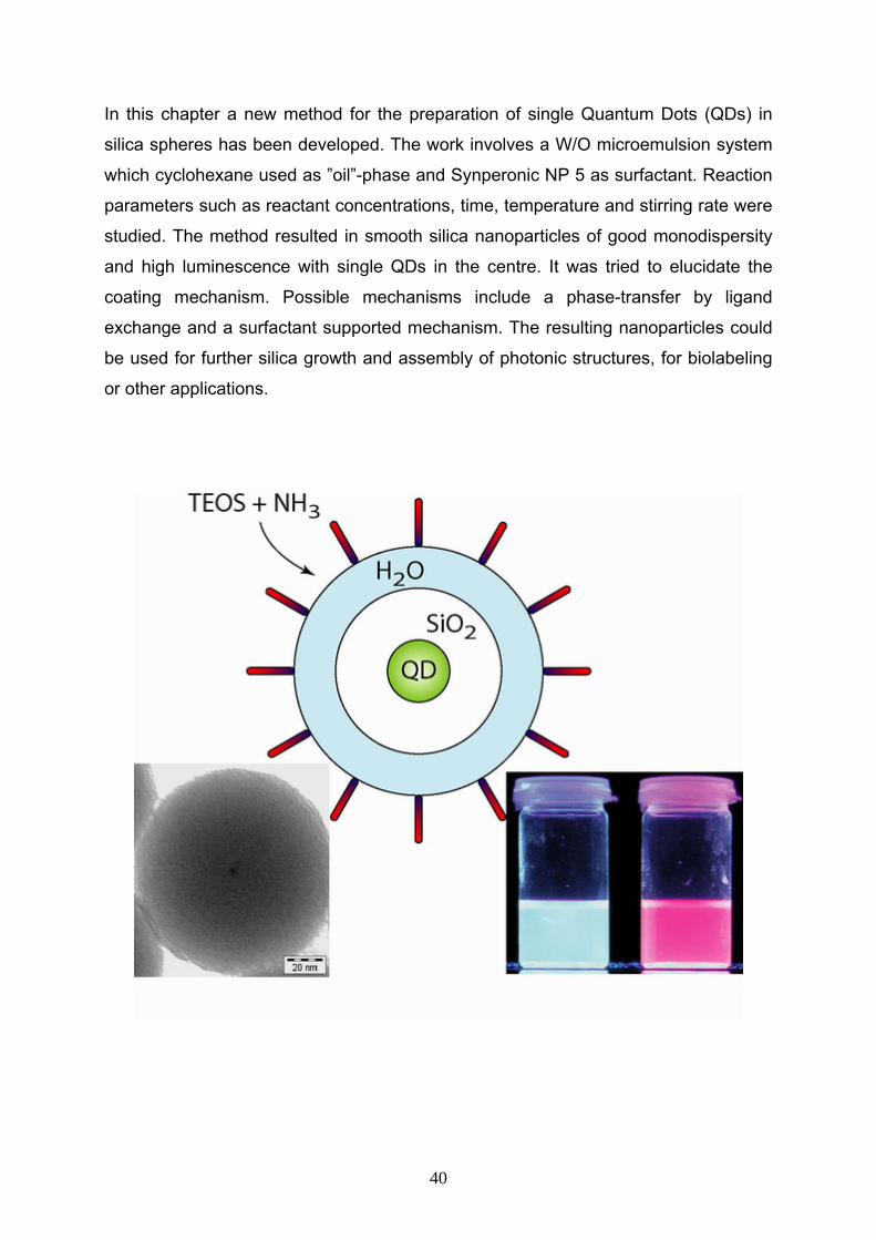
In this chapter a new method for the preparation of single Quantum Dots (QDs) in
silica spheres has been developed. The work involves a W/O microemulsion system
which cyclohexane used as ”oil”-phase and Synperonic NP 5 as surfactant. Reaction
parameters such as reactant concentrations, time, temperature and stirring rate were
studied. The method resulted in smooth silica nanoparticles of good monodispersity
and high luminescence with single QDs in the centre. It was tried to elucidate the
coating mechanism. Possible mechanisms include a phase-transfer by ligand
exchange and a surfactant supported mechanism. The resulting nanoparticles could
be used for further silica growth and assembly of photonic structures, for biolabeling
or other applications.
40
2-1 Introduction Semiconductor nanocrystals, especially II–VI and III–V compounds, have attracted
considerable attention for practical applications such as catalysis, photovoltaic,
phosphors, light emitting diodes and the labelling of biological molecules. Probably,
this attention is mainly caused by their mesoscopic properties compared to the
corresponding bulk materials of the same composition, which by controlling the size
of the these nanoparticles below the exciton diameter, the emission and absorbtion
edge of these particles can be tuned in the wide range of visible region (1-9) .
Among II–VI semiconductors, a huge amount of work has been done on CdS and
CdSe nanoparticles, the list being too exhaustive to be listed here (10-13). Typically,
CdSe is covered with a ZnS shell to enhance its quantum yield (QY) for radiative
band gap recombination and to protect the core against photo-oxidation as well as
chemical and physical stress (14, 15). Based of above mentioned reasons,
CdSe/ZnS core-shell nanocrystals have been chosen as model for single QD
encapsulation in this chapter.
Meanwhile, the preparation of monodisperse nanoparticles with several techniques is
well established. For instance, a high-temperature organometallic procedure first
published by Murray et al. (16) and subsequently improved by Hines et al. (17) led to
highly monodisperse, passivated CdSe/ZnS core-shell nanocrystals. Nevertheless,
almost any (potential) application of nanoparticles requires a further derivatisation of
such particles as pre-requisite. Hybrid nanostructures such as biomolecule
nanoparticle conjugates, (9) metal-semiconductor nanohybrides (18) or polymer-
nanocrystal hybrids (19) are important steps towards applications of these
nanomaterials. Among these hybrid core-shell materials, silica coated nanoparticles
attracted grate attention in recent decades.
Encapsulation of single nanoparticles with silica shells is advantageous for
applications such as biolabelling, because silica surfaces are easy to functionalise,
non-toxic and protect the surface of the nanoparticles from oxidation. Furthermore,
silica particles can be increased in size by ”seeded” growth (20) and assembled to
bigger aggregates like photonic crystals (21).
The present chapter describes a simple and straightforward method for the
encapsulation of single CdSe/ZnS nanoparticles with monodisperse silica
nanospheres. The microemulsion system has been choosen as media for
41
encapsulation because of most advantage in compare with other methods (which is
already mentioned in chapter 1). The reaction parameters were investigated for
finding optimum condition of encapsulation, and also the encapsulation mechanism
studied. Even though it was not possible to completely elucidate the coating
mechanism.
2-2 Experimental Section
2-2-1 Chemicals Tetraethylorthosilicate (TEOS) 99.999% was purchased from Aldrich, cadmium
stearate from Strem Chemicals, tri-n-octylphosphine oxide (TOPO) from Avocado,
selenium from Merk, Polyethylene glycol nonylphenyl ether (Synperonic NP-5) from
Fluka, ammonia aqueous solution (33 wt%), cyclohexane, acetone, butanol,
propanol, ethanol from internal sources. All chemicals were used for the synthesis as
received.
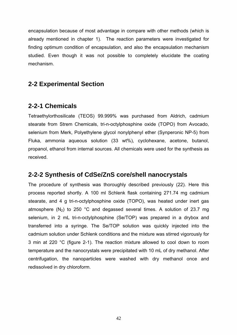
2-2-2 Synthesis of CdSe/ZnS core/shell nanocrystals The procedure of synthesis was thoroughly described previously (22). Here this
process reported shortly. A 100 ml Schlenk flask containing 271.74 mg cadmium
stearate, and 4 g tri-n-octylphosphine oxide (TOPO), was heated under inert gas
atmosphere (N2) to 250 °C and degassed several times. A solution of 23.7 mg
selenium, in 2 mL tri-n-octylphosphine (Se/TOP) was prepared in a drybox and
transferred into a syringe. The Se/TOP solution was quickly injected into the
cadmium solution under Schlenk conditions and the mixture was stirred vigorously for
3 min at 220 °C (figure 2-1). The reaction mixture allowed to cool down to room
temperature and the nanocrystals were precipitated with 10 mL of dry methanol. After
centrifugation, the nanoparticles were washed with dry methanol once and
redissolved in dry chloroform.
42
20o
Figure 2-1. Synthetic set up for preparation of CdSe/ZnS core/shell nanocrystals
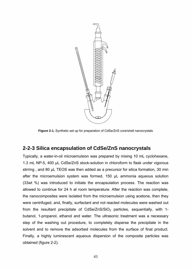
2-2-3 Silica encapsulation of CdSe/ZnS nanocrystals Typically, a water-in-oil microemulsion was prepared by mixing 10 mL cyclohexane,
1.3 mL NP-5, 400 µL CdSe/ZnS stock-solution in chloroform to flask under vigorous
stirring , and 80 µL TEOS was then added as a precursor for silica formation, 30 min
after the microemulsion system was formed, 150 µL ammonia aqueous solution
(33wt %) was introduced to initiate the encapsulation process. The reaction was
allowed to continue for 24 h at room temperature. After the reaction was complete,
the nanocomposites were isolated from the microemulsion using acetone, then they
were centrifuged, and, finally, surfactant and not reacted molecules were washed out
from the resultant precipitate of CdSe/ZnS/SiO2 particles, sequentially, with 1-
butanol, 1-propanol, ethanol and water. The ultrasonic treatment was a necessary
step of the washing out procedure, to completely disperse the precipitate in the
solvent and to remove the adsorbed molecules from the surface of final product.
Finally, a highly luminescent aqueous dispersion of the composite particles was
obtained (figure 2-2).
43
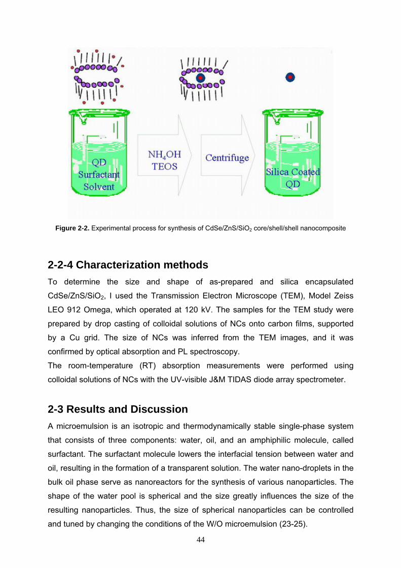
Figure 2-2. Experimental process for synthesis of CdSe/ZnS/SiO2 core/shell/shell nanocomposite
2-2-4 Characterization methods To determine the size and shape of as-prepared and silica encapsulated
CdSe/ZnS/SiO2, I used the Transmission Electron Microscope (TEM), Model Zeiss
LEO 912 Omega, which operated at 120 kV. The samples for the TEM study were
prepared by drop casting of colloidal solutions of NCs onto carbon films, supported
by a Cu grid. The size of NCs was inferred from the TEM images, and it was
confirmed by optical absorption and PL spectroscopy.
The room-temperature (RT) absorption measurements were performed using
colloidal solutions of NCs with the UV-visible J&M TIDAS diode array spectrometer.
2-3 Results and Discussion A microemulsion is an isotropic and thermodynamically stable single-phase system
that consists of three components: water, oil, and an amphiphilic molecule, called
surfactant. The surfactant molecule lowers the interfacial tension between water and
oil, resulting in the formation of a transparent solution. The water nano-droplets in the
bulk oil phase serve as nanoreactors for the synthesis of various nanoparticles. The
shape of the water pool is spherical and the size greatly influences the size of the
resulting nanoparticles. Thus, the size of spherical nanoparticles can be controlled
and tuned by changing the conditions of the W/O microemulsion (23-25).
44
In a typical synthesis, cyclohexane served as continuous phase in which TEOS,
surfactant (preferably Synperonic NP 5) and hydrophobically ligated QDs (usually
with trioctylphosphineoxide (TOPO) ligands) were dissolved. Subsequently, the
ammonia catalyst was added. It was found, that the size, monodispersity, multiplicity
of QDs per silica particle and overall quality of the resulting QD/silica particles is
governed by reaction conditions such as time, temperature, concentration of
reactants, and speed of stirring. The influence of these conditions was studied
systematically and optimised in order to yield monodisperse, well-defined
nanoparticles.
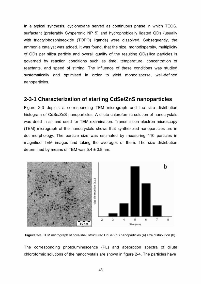
2-3-1 Characterization of starting CdSe/ZnS nanoparticles Figure 2-3 depicts a corresponding TEM micrograph and the size distribution
histogram of CdSe/ZnS nanoparticles. A dilute chloroformic solution of nanocrystals
was dried in air and used for TEM examination. Transmission electron microscopy
(TEM) micrograph of the nanocrystals shows that synthesized nanoparticles are in
dot morphology. The particle size was estimated by measuring 110 particles in
magnified TEM images and taking the averages of them. The size distribution
determined by means of TEM was 5.4 ± 0.8 nm.
Figure 2-3. TEM micrograph of core/shell structured CdSe/ZnS nanoparticles (a) size distribution (b).
The corresponding photoluminescence (PL) and absorption spectra of dilute
chloroformic solutions of the nanocrystals are shown in figure 2-4. The particles have
45
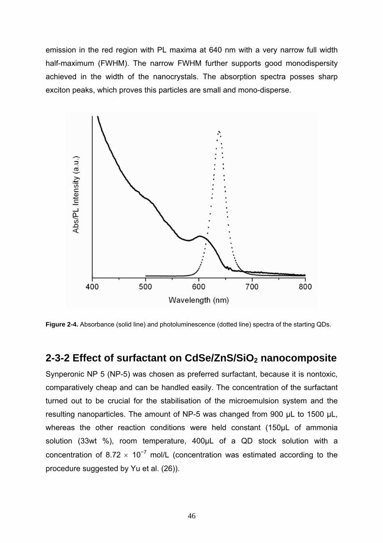
emission in the red region with PL maxima at 640 nm with a very narrow full width
half-maximum (FWHM). The narrow FWHM further supports good monodispersity
achieved in the width of the nanocrystals. The absorption spectra posses sharp
exciton peaks, which proves this particles are small and mono-disperse.
Figure 2-4. Absorbance (solid line) and photoluminescence (dotted line) spectra of the starting QDs.
2-3-2 Effect of surfactant on CdSe/ZnS/SiO2 nanocomposite Synperonic NP 5 (NP-5) was chosen as preferred surfactant, because it is nontoxic,
comparatively cheap and can be handled easily. The concentration of the surfactant
turned out to be crucial for the stabilisation of the microemulsion system and the
resulting nanoparticles. The amount of NP-5 was changed from 900 µL to 1500 µL,
whereas the other reaction conditions were held constant (150µL of ammonia
solution (33wt %), room temperature, 400µL of a QD stock solution with a
concentration of 8.72 × 10⁻⁷ mol/L (concentration was estimated according to the
procedure suggested by Yu et al. (26)).
46
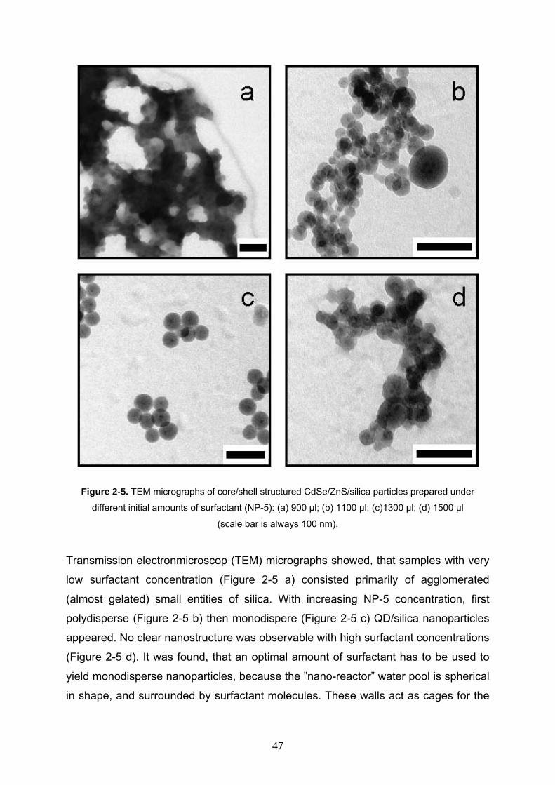
Figure 2-5. TEM micrographs of core/shell structured CdSe/ZnS/silica particles prepared under
different initial amounts of surfactant (NP-5): (a) 900 µl; (b) 1100 µl; (c)1300 µl; (d) 1500 µl
(scale bar is always 100 nm).
Transmission electronmicroscop (TEM) micrographs showed, that samples with very
low surfactant concentration (Figure 2-5 a) consisted primarily of agglomerated
(almost gelated) small entities of silica. With increasing NP-5 concentration, first
polydisperse (Figure 2-5 b) then monodispere (Figure 2-5 c) QD/silica nanoparticles
appeared. No clear nanostructure was observable with high surfactant concentrations
(Figure 2-5 d). It was found, that an optimal amount of surfactant has to be used to
yield monodisperse nanoparticles, because the ”nano-reactor” water pool is spherical
in shape, and surrounded by surfactant molecules. These walls act as cages for the
47
growing particles and thereby control the average size of the particles during the
collision and aggregation process.
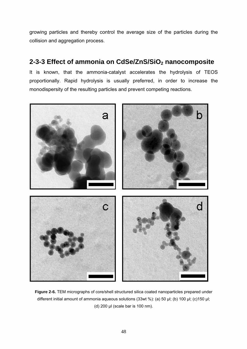
2-3-3 Effect of ammonia on CdSe/ZnS/SiO2 nanocomposite It is known, that the ammonia-catalyst accelerates the hydrolysis of TEOS
proportionally. Rapid hydrolysis is usually preferred, in order to increase the
monodispersity of the resulting particles and prevent competing reactions.
Figure 2-6. TEM micrographs of core/shell structured silica coated nanoparticles prepared under
different initial amount of ammonia aqueous solutions (33wt %): (a) 50 µl; (b) 100 µl; (c)150 µl;
(d) 200 µl (scale bar is 100 nm).
48
Moreover, the pH-value of the solution increases with increasing ammonia
concentration. Therefore, the electrostatic stabilisation of the colloid should be
increased. Accordingly the ionic strength of the solution increases, which destabilises
the microemulsion system.
The influence of the ammonia solution concentration was studied within the range
of 50 µL to 200 µL of ammonia (33wt % aqueous solution), whereas all the other
reaction parameters were held constant (as mentioned above). It was observed, that
with low ammonia concentrations (Figure 2-6 a), irregular silica structures were built.
With increasing concentration, first polydisperse nanoparticles with multiple QDs
(Figure 2-6 b), then monodisperse nanoparticles with single QDs appeared (Figure 2-
6 c). When the ammonia concentration was further increased (Figure 2-6 d), irregular
structures were observed besides relatively monodisperse QD/silicas.
These observations demonstrate, that the monodispersity is lost with low catalyst
concentrations due to slow hydrolysis and with high concentrations due to
destabilisation of the microemulsion.
2-3-4 Effect of TEOS on CdSe/ZnS/SiO2 nanocomposite The amount of added TEOS is expected to directly influence the size of the resulting
nanoparticles. The TEOS was changed from 5 µL to 150 µL, whereas all other
parameters were held constant as described above.
It was found, that with an amount of below 30 µL, only irregular silica structures were
formed (figure 2-7 a,b). Between 30 µL and 100 µL of TEOS, single silica coated
QDs were found with a proportionally increasing size, dependent on the TEOS
concentration. The particles at the limits of this concentration range (viz. 30 and 100
µL) were found to be relatively polydisperse (figure 2-7 c,d). The optimal amount of
TEOS under these conditions was determined at 80 µL (Figure 2-7 e). With
concentrations above 100 µL, again irregular structures were observed (Figure 2-7 f).
49
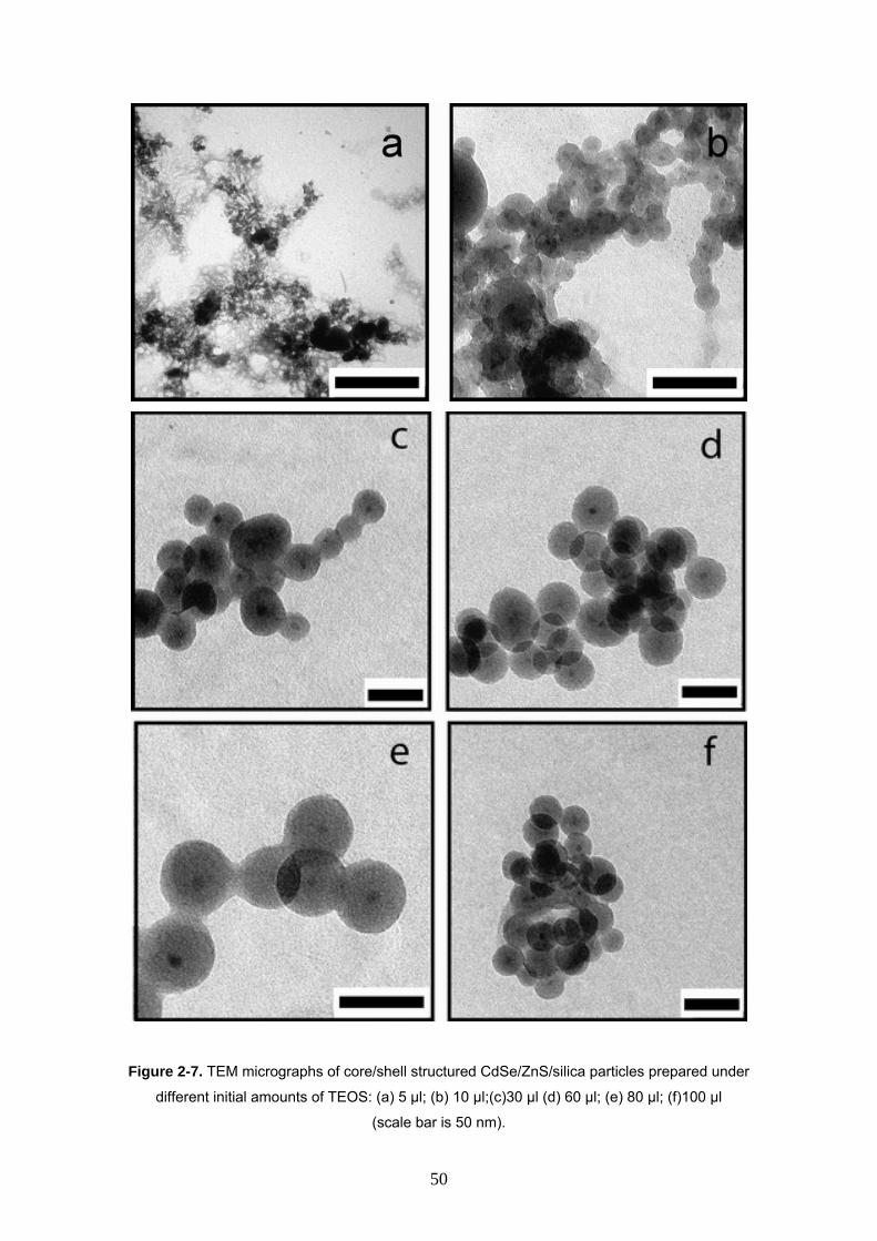
Figure 2-7. TEM micrographs of core/shell structured CdSe/ZnS/silica particles prepared under
different initial amounts of TEOS: (a) 5 µl; (b) 10 µl;(c)30 µl (d) 60 µl; (e) 80 µl; (f)100 µl
(scale bar is 50 nm).
50
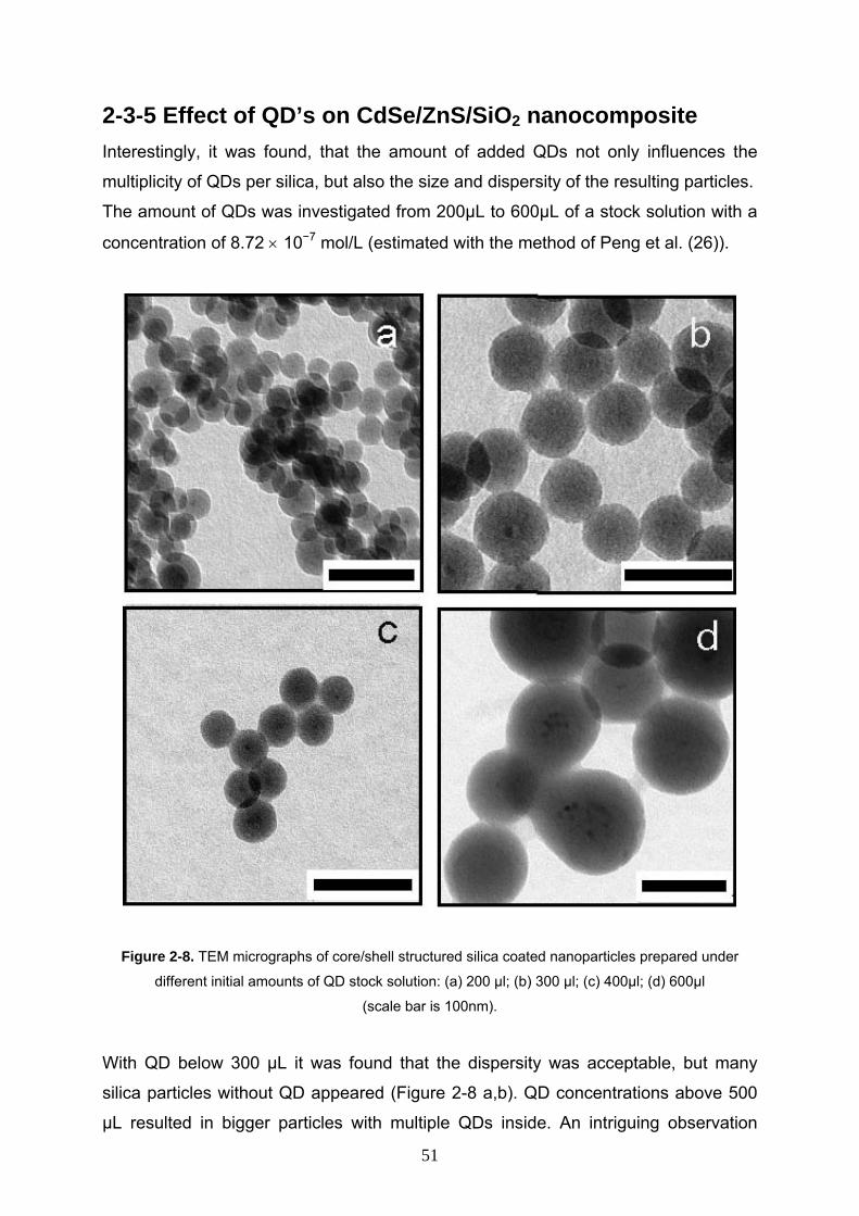
2-3-5 Effect of QD’s on CdSe/ZnS/SiO2 nanocomposite Interestingly, it was found, that the amount of added QDs not only influences the
multiplicity of QDs per silica, but also the size and dispersity of the resulting particles.
The amount of QDs was investigated from 200µL to 600µL of a stock solution with a
concentration of 8.72 × 10⁻⁷ mol/L (estimated with the method of Peng et al. (26)).
Figure 2-8. TEM micrographs of core/shell structured silica coated nanoparticles prepared under
different initial amounts of QD stock solution: (a) 200 µl; (b) 300 µl; (c) 400µl; (d) 600µl
(scale bar is 100nm).
With QD below 300 µL it was found that the dispersity was acceptable, but many
silica particles without QD appeared (Figure 2-8 a,b). QD concentrations above 500
µL resulted in bigger particles with multiple QDs inside. An intriguing observation
51
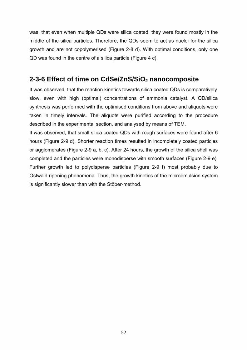
was, that even when multiple QDs were silica coated, they were found mostly in the
middle of the silica particles. Therefore, the QDs seem to act as nuclei for the silica
growth and are not copolymerised (Figure 2-8 d). With optimal conditions, only one
QD was found in the centre of a silica particle (Figure 4 c).
2-3-6 Effect of time on CdSe/ZnS/SiO2 nanocomposite It was observed, that the reaction kinetics towards silica coated QDs is comparatively
slow, even with high (optimal) concentrations of ammonia catalyst. A QD/silica
synthesis was performed with the optimised conditions from above and aliquots were
taken in timely intervals. The aliquots were purified according to the procedure
described in the experimental section, and analysed by means of TEM.
It was observed, that small silica coated QDs with rough surfaces were found after 6
hours (Figure 2-9 d). Shorter reaction times resulted in incompletely coated particles
or agglomerates (Figure 2-9 a, b, c). After 24 hours, the growth of the silica shell was
completed and the particles were monodisperse with smooth surfaces (Figure 2-9 e).
Further growth led to polydisperse particles (Figure 2-9 f) most probably due to
Ostwald ripening phenomena. Thus, the growth kinetics of the microemulsion system
is significantly slower than with the Stöber-method.
52
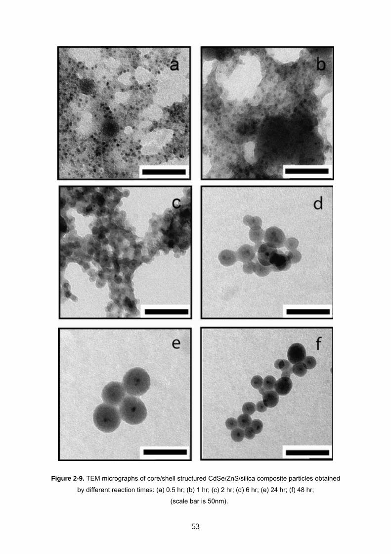
Figure 2-9. TEM micrographs of core/shell structured CdSe/ZnS/silica composite particles obtained
by different reaction times: (a) 0.5 hr; (b) 1 hr; (c) 2 hr; (d) 6 hr; (e) 24 hr; (f) 48 hr;
(scale bar is 50nm).
53
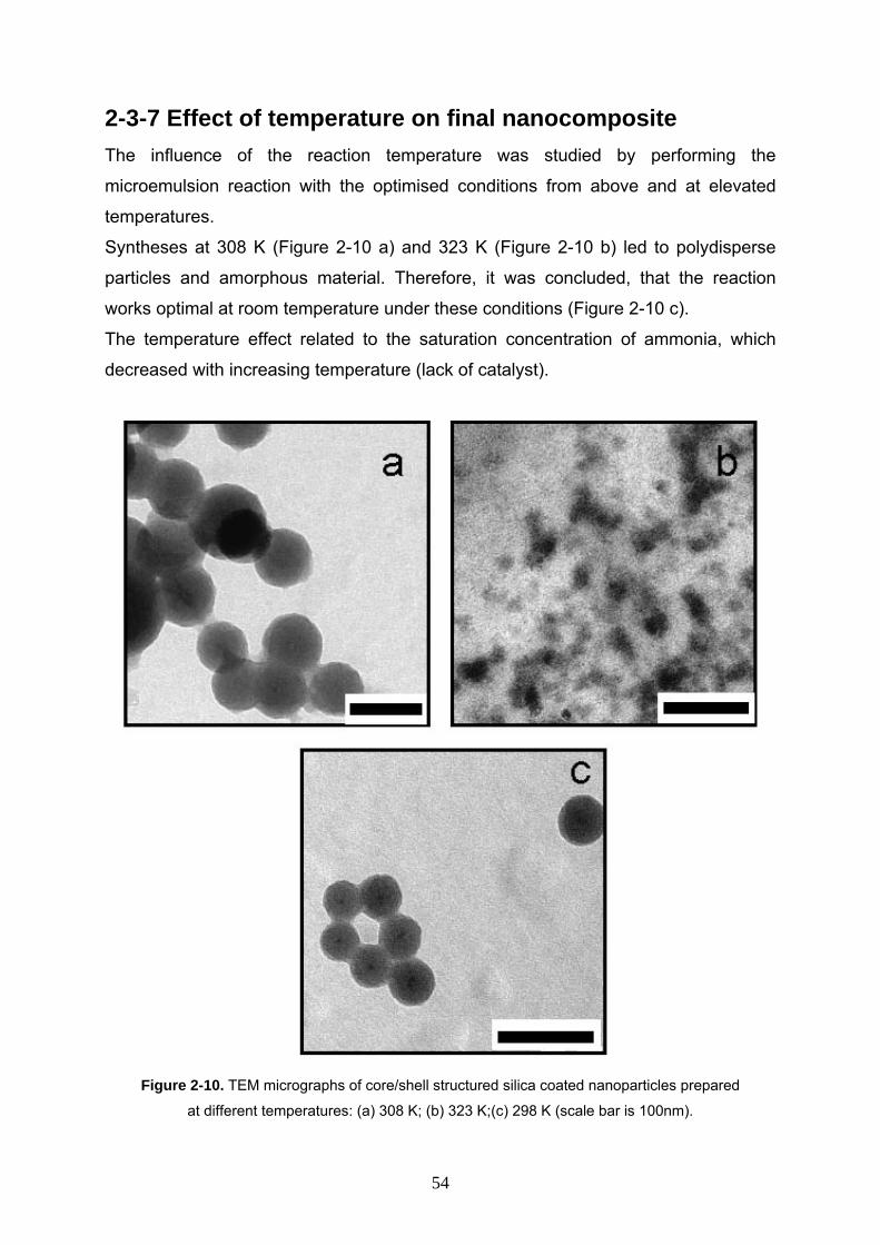
2-3-7 Effect of temperature on final nanocomposite The influence of the reaction temperature was studied by performing the
microemulsion reaction with the optimised conditions from above and at elevated
temperatures.
Syntheses at 308 K (Figure 2-10 a) and 323 K (Figure 2-10 b) led to polydisperse
particles and amorphous material. Therefore, it was concluded, that the reaction
works optimal at room temperature under these conditions (Figure 2-10 c).
The temperature effect related to the saturation concentration of ammonia, which
decreased with increasing temperature (lack of catalyst).
Figure 2-10. TEM micrographs of core/shell structured silica coated nanoparticles prepared
at different temperatures: (a) 308 K; (b) 323 K;(c) 298 K (scale bar is 100nm).
54
2-3-8 Effect of stirring on CdSe/ZnS/SiO2 nanocomposite Previous publications reported a great influence of the stirring rate on the resulting
nanoparticles (20). Therefore, two identical syntheses were performed with the
optimised conditions, except one with high (above 10000 rpm) and the other with low
stirring rate (about 1000 rpm).
Figure 2-11. TEM micrographs of core/shell structured CdSe/ZnS/silica nanocomposite particles
obtained by different stirring rates: (a) 1000 rpm; (b) 10000 rpm (scale bar is 50nm).
It was observed, that the sample with low stirring rate resulted in polydisperse
particles and that many particles contained multiple QDs (Figure 2-11 a). A high
stirring rate seems to be necessary in order to form a stable microemulsion (Figure 2-
11 b).
2-3-9 Room temperature photoluminescence and absorption spectra of CdSe/ZnS/SiO2 nanocomposite The silica coated QDs showed a strong photoluminescence. Figure (2-12 a) depicts
the increase in absorption at the first excited state of the QDs (620 nm) on
preparation of the silica shell. It was observed that the absorption increases almost
linearly with the time, indicating a successive growth of the silica shell. Figure (2-12
b) shows the normalized luminescence spectra of nanoparticles before and after
55
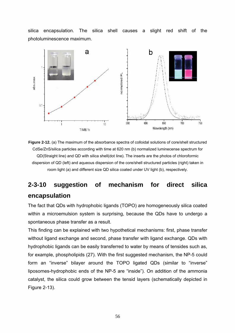
silica encapsulation. The silica shell causes a slight red shift of the
photoluminescence maximum.
Figure 2-12. (a) The maximum of the absorbance spectra of colloidal solutions of core/shell structured
CdSe/ZnS/silica particles according with time at 620 nm (b) normalized luminecense spectrum for
QD(Straight line) and QD with silica shell(dot line). The inserts are the photos of chloroformic
dispersion of QD (left) and aqueous dispersion of the core/shell structured particles (right) taken in
room light (a) and different size QD silica coated under UV light (b), respectively.
2-3-10 suggestion of mechanism for direct silica encapsulation
The fact that QDs with hydrophobic ligands (TOPO) are homogeneously silica coated
within a microemulsion system is surprising, because the QDs have to undergo a
spontaneous phase transfer as a result.
This finding can be explained with two hypothetical mechanisms: first, phase transfer
without ligand exchange and second, phase transfer with ligand exchange. QDs with
hydrophobic ligands can be easily transferred to water by means of tensides such as,
for example, phospholipids (27). With the first suggested mechanism, the NP-5 could
form an “inverse” bilayer around the TOPO ligated QDs (similar to “inverse”
liposomes-hydrophobic ends of the NP-5 are “inside”). On addition of the ammonia
catalyst, the silica could grow between the tensid layers (schematically depicted in
Figure 2-13).
56
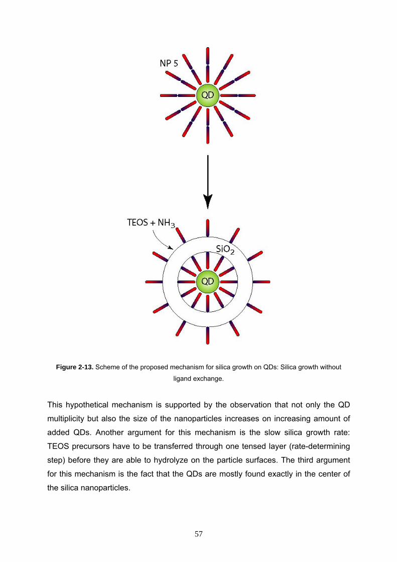
Figure 2-13. Scheme of the proposed mechanism for silica growth on QDs: Silica growth without
ligand exchange.
This hypothetical mechanism is supported by the observation that not only the QD
multiplicity but also the size of the nanoparticles increases on increasing amount of
added QDs. Another argument for this mechanism is the slow silica growth rate:
TEOS precursors have to be transferred through one tensed layer (rate-determining
step) before they are able to hydrolyze on the particle surfaces. The third argument
for this mechanism is the fact that the QDs are mostly found exactly in the center of
the silica nanoparticles.
57
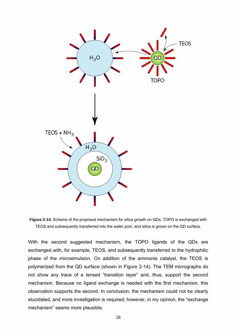
Figure 2-14. Scheme of the proposed mechanism for silica growth on QDs: TOPO is exchanged with
TEOS and subsequently transferred into the water pool, and silica is grown on the QD surface.
With the second suggested mechanism, the TOPO ligands of the QDs are
exchanged with, for example, TEOS, and subsequently transferred to the hydrophilic
phase of the microemulsion. On addition of the ammonia catalyst, the TEOS is
polymerized from the QD surface (shown in Figure 2-14). The TEM micrographs do
not show any trace of a tensed “transition layer” and, thus, support the second
mechanism. Because no ligand exchange is needed with the first mechanism, this
observation supports the second. In conclusion, the mechanism could not be clearly
elucidated, and more investigation is required; however, in my opinion, the “exchange
mechanism” seems more plausible.
58
2-4 Conclusion
In conclusion, a new, straightforward, one-pot method for homogeneous silica
coating of single QDs was presented and investigated. Different reaction conditions
for the encapsulation by microemulsion were studied, and it was found that with
optimized conditions, highly monodisperse silica coatings can be prepared. In
contrast to a previously published, “Stöber” based method, (28) which the procedure
is very robust against slight changes with the reaction parameters and the purity of
reactants. Furthermore, it can be easily scaled-up and no purification steps are
required during preparation of the silica shell. It was not possible to elucidate the
encapsulation mechanism completely, but the experimental results point in the
direction of a ligand-exchange/phase-transfer mechanism.
The resulting nanoparticles could be used for further silica growth and assembly of
photonic structures, for biolabeling, or for other applications.
59
References 1- V. L. Colvin, M. C. Schlamp, A. P. Alivisatos, Nature, 1994, 370, 354.
2- B. O. Dabbousi, M. G. Bawendi, O. Onitsuka, M. F. Rubner, Appl. Phys. Lett.,
1995, 66, 1316.
3- W. U. Huynh, X. Peng, A. P. Alivisatos, Adv. Mater., 1999, 11, 923.
4- W. U. Huynh, J. J. Dittmer, A. P. Alivisatos, Science, 2002, 295, 2425.
5- S. Kumar, T. Nann, J. Mater. Res., 2004, 19, 1990.
6- T. S. Ahmadi, Z. L. Wang, T. Green, A. Henglein, M. A. Elsayed, Science, 1996,
272, 1924.
7- M. Bruchez, M. Moronne, P. Gin, S. Weiss, A. P. Alivisatos, Science, 1998, 281,
2013.
8- W. C. W. Chan, S. Nie, Science, 1998, 281, 2016.
9- J. Riegler, P. Nick, U. Kielmann, T. Nann, J. Nanosci. Nanotech., 2003, 3, 380.
10- M. A. Malik, N. Ravaprasadu, P. O’Brien, Chem. Mater. 2001, 13, 913.
11- Z. Xue, A. D. Terepka, Y. Hong, Nano Lett. 2004, 4, 2227.
12- E. Comer, M. G. Organ, J. Am. Chem. Soc. 2005, 127, 8160.
13- J. J. Zhu, O. Palchik, S. G. Chen, A. Gedanken, J. Phys. Chem. B 2000, 104,
7344.
14- M. A. Hines, P. Guyot-Sionnest, J. Phys. Chem. 1996, 100, 468.
15- R. Xie, U. Kolb, J. Li, T. Basche, A. Mews, J. Am Chem. Soc. 2005, 127, 7480.
16- C. B. Murray, D. J. Norris, M. G. Bawendi, J. Am. Chem. Soc., 1993, 115, 8706.
17- M. A. Hines, P. Guyot-Sionnest, J. Phys. Chem., 1996, 100, 468.
18- J. Enderlein, Appl. Phys. Lett., 2002, 80, 315.
19- E. Kucur, J. Riegler, G. A. Urban, T. Nann, J. Chem. Phys., 2004, 120, 1500.
20- G. H. Bogush, M. A. Tracy, C. F. Z. IV, J. Non-Cryst. Solids, 1988, 104, 95.
21- F. García-Santamaría, V. Salgueirino-Maceira, C. López, L. M. Liz-Marzán,
Langmuir, 2002, 18, 4519.
22- E. Kucur, J. Riegler, G. A. Urban, T. Nann, J. Chem. Phys., 2003, 119, 2333.
23- M. Bonini, A. Wiedenmann, P. Baglioni, Physica A, 2004, 339, 86.
24- T. Mokari, H. Sertchook, A. Aharoni, Y. Ebenstein, D. Avnir, U. Banin, Chem.
Mater, 2005, 17, 258.
25- F. Teng, Z. Tian, G. Xiong, Z. Xu, Catal. Today, 2004, 93-95, 651.
26- W. W. Yu, L. Qu, W. Guo, X. Peng, Chem. Mater., 2003, 15, 2854.
27- B.Dubertret, P. Skourides, D. Norris, V.Noireaux, A. Brivanlou, A.Libchaber,
60

Science, 2002, 298, 1759.
28- W. Stöber, A. Fink, E. Bohn, J. Colloid Interface Sci., 1968, 26, 62.
61
Chapter 3
Generality of silica encapsulation in
microemulsion for hydrophobically ligated
nanoparticles
62
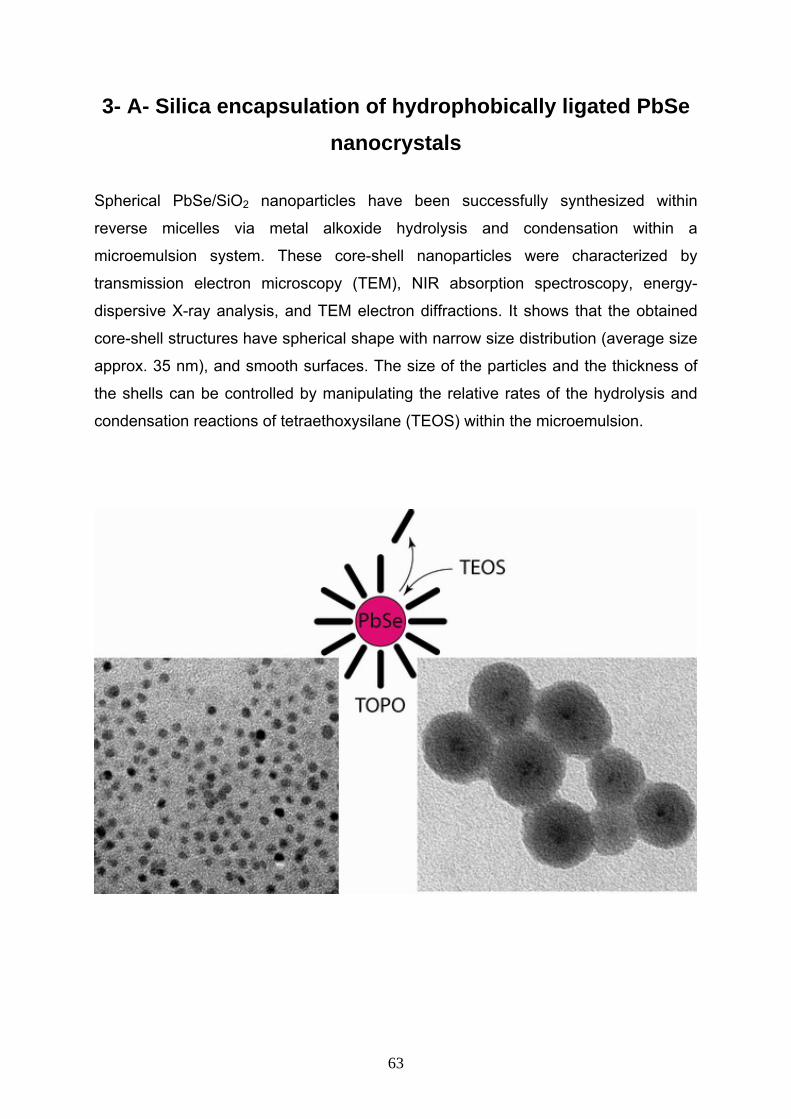
3- A- Silica encapsulation of hydrophobically ligated PbSe nanocrystals
Spherical PbSe/SiO2 nanoparticles have been successfully synthesized within
reverse micelles via metal alkoxide hydrolysis and condensation within a
microemulsion system. These core-shell nanoparticles were characterized by
transmission electron microscopy (TEM), NIR absorption spectroscopy, energy-
dispersive X-ray analysis, and TEM electron diffractions. It shows that the obtained
core-shell structures have spherical shape with narrow size distribution (average size
approx. 35 nm), and smooth surfaces. The size of the particles and the thickness of
the shells can be controlled by manipulating the relative rates of the hydrolysis and
condensation reactions of tetraethoxysilane (TEOS) within the microemulsion.
63
3- A- 1 Introduction In last chapter (chapter 2) simple approach has been shown for silica encapsulation
of QD’s. To prove the generality of the process for encapsulation of organically
capped nanoparticles, PbSe and YV(0.7)P(0.3)O4:Eu3+, Bi3+ nanoparticles has been
chosen for silica encapsulation, which PbSe NC’s would be discussed in detail in part
A and YV(0.7)P(0.3)O4:Eu3+, Bi3+ NC’s in part B of this chapter.
PbSe NCs have attracted considerable interest because of their intriguing properties
and structural diversity. In PbSe, the electron, hole, and exciton Bohr radii are 23, 23,
and 46 nm, respectively. These large radii allow strong confinement to be achieved in
relatively large structures. These structures may find use in optoelectronic
applications as well as in biophysical applications such as fluorescence microscopy,
because lead chalcogenide nanocrystals emit near-infrared (NIR) light, and their high
nonlinearities make them excellent materials for optical switches. The near-infrared
emission is also an ideal property for biological imaging, tissue has a window in
absorbance between 700 and 1150 nm, which makes NIR labels of special
importance. Near-infrared emitting nanocrystals could in principle be applied to in
vivo biomedical application (imaging and labeling) where detection may occur
through 1-20 mm of tissues. PbSe NCs are promising candidates for a wide variety of
potential applications such as IR detectors, photographic plates, selective and
photovoltaic absorbers, and others. During the past two decades, PbSe NCs have
been intensively studied (1-7).
They have been prepared by various methods such as chemical bath deposition,
molecular beam epitaxy, vacuum deposition, electrodeposition, the pulse
sonoelectrochemical method, the photochemical method, microwave assisted
heating, and the successive ion layer adsorption and reaction technique (8-10).
Murray et al. (11) synthesized discrete spherical PbSe NCs, with narrow size
distribution and tunable band-gap at the near IR spectral regime (0.5-1.1 eV), which it
has been proved by electron microscopy and optical absorption spectra. Lifshitz et al. (12) reported a synthetic procedure for the preparation of discrete spherical
PbSe/PbS core-shell NCs, with average sizes ranging between 2.5-7 nm, and with
enhanced photoluminescence quantum yield. Syntheses of very small PbSe
nanocrystals (d = 2-3 nm) as well as larger PbSe quantum wires, rods, and cubes
have also been recently reported (13, 14).
64
The as-prepared PbSe NP’s are organically stabilized nanocrystals and are
dispersible in organic solvents such as toluene, chloroform, and hexane. However,
for some applications especially for biological studies water-dispersible materials are
essential. It is straightforward to make water-dispersible PbSe semiconductor
nanocrystals through encapsulation with silica shell. With this surface modification
the Problems like bent surfaces, dangling bonds, (photo-) oxidation, coalescence,
and other instabilities (15,16) which increasingly important with decreasing
nanocrystal size, could be vanished or exhausted.
To my best knowledge, studies on silica encapsulated PbSe NCs have not been
achieved so far. Guided by these considerations mentioned above, and regarding
that it is desirable in view of industrial applications to coat the nanoparticles by a
more convenient method, I demonstrate a simple method by which monodisperse
silica coated PbSe can be prepared using water-in-oil (W/O) microemulsion
containing NP-5, cyclohexan and water system. In this chapter the details of this
synthesis approach has been metioned. The procedure yields nanocrystals
encapsulated in a silica shell with a thickness of about 14 nm. In order to prevent the
dissolution of the PbSe cores, dimethylamine was used as catalyst for the hydrolysis
and condensation of tetraethoxysilane (TEOS).
3- A- 2 Experimental section 3- A- 2- 1 Chemicals
All of the chemicals were used as received from Aldrich without further purification.
Polyethylene glycol nonylphenyl ether (Synperonic NP 5) was purchased from Fluka,
ammonia aqueous solution (33 wt %), dimethylamine (40 wt %), cyclohexane,
acetone, butanol, propanol, and ethanol from internal sources.
3- A- 2- 2 Synthesis of PbSe nanocrystals The synthesis approach of PbSe NCs is based on a procedure developed by C. B.
Murray et al. (17-19) using a similar device. Typically, 1.081g of lead acetate
[Pb(Ac)2•3H2O, 99.999%] was added into 15 mL of phenyl ether (99%) in the
65
presence of 3.6 mL of oleic acid (90%) with constant agitation. The mixture was
heated up to 150 oC under flowing argon, remained for 30 min, and then cooled to
room temperature. Under argon atmosphere, this cooled solution was subsequently
mixed with 8 mL of Se-TOP solution (1M for Se) which was pre-prepared by
dissolving metallic selenium (99.99%) into trioctylphosphine (TOP, 90%) in a glovbox,
and rapidly injected into 15 mL of hot phenyl ether which was heated to 180 oC under
argon stream on a Schlenk line. The hot mixture was vigorously stirred for 6 min. The
resulting PbSe colloids were cooled to room temperature by quickly removing the
heating source, and then isolated by adding a sufficient amount of ethanol and by
separating with centrifugation. The resulting precipitate was re-dispersed in hexane
followed by a size-selection treatment. The overall yield was around 65-80 wt%.
3- A- 2- 3 Silica encapsulation of PbSe nanocrystals The PbSe/SiO2 particles were prepared by a modified W/O microemulsion method at
room temperature. The microemulsion system was made up of cyclohexane, NP-5,
PbSe and dimethylamine. Typically, 10 ml cyclohexane, 1.3 ml NP-5, 400 µl PbSe
stock-solution (8.72 × 10⁻⁷ mol/L ) and 50 µl TEOS (99.999 %) were added in a glass
container under vigorous stirring. 30 min after the microemulsion system was formed,
100 µl dimethylamine aqueous solution (40wt %) was introduced to initiate the
polymerization process. Following the reaction, the first evidence for silica-
encapsulation is provided by the colour of the precipitate containing the composites,
which are typical for specific NCs and their sizes and the disappearance of that
colour from the solution by an increase of light scattering. The silica growth was
completed after 24 h of stirring. The nanoparticles were destabilized from the
microemulsion using acetone and precipitated by centrifugation. The resultant
precipitate of PbSe/SiO2 composite particles was washed in sequence with 1-
butanol, 1-propanol, ethanol and water to remove any possible surfactant and
unreacted molecules. For each washing step, followed by centrifugation, a sonicator
bath was used to completely disperse the precipitate in the corresponding solvent
and remove any physically adsorbed molecules from the particle surfaces. Finally,
aqueous dispersions of the composite particles were obtained.
66
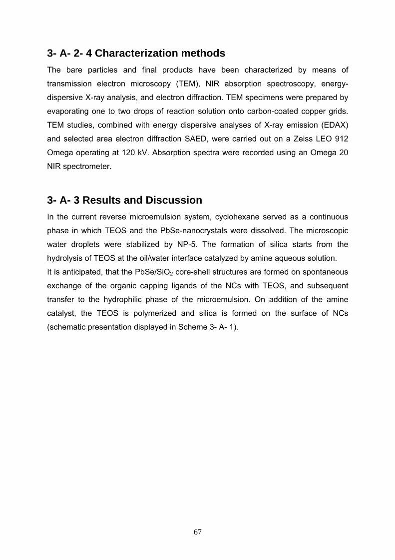
3- A- 2- 4 Characterization methods The bare particles and final products have been characterized by means of
transmission electron microscopy (TEM), NIR absorption spectroscopy, energy-
dispersive X-ray analysis, and electron diffraction. TEM specimens were prepared by
evaporating one to two drops of reaction solution onto carbon-coated copper grids.
TEM studies, combined with energy dispersive analyses of X-ray emission (EDAX)
and selected area electron diffraction SAED, were carried out on a Zeiss LEO 912
Omega operating at 120 kV. Absorption spectra were recorded using an Omega 20
NIR spectrometer.
3- A- 3 Results and Discussion In the current reverse microemulsion system, cyclohexane served as a continuous
phase in which TEOS and the PbSe-nanocrystals were dissolved. The microscopic
water droplets were stabilized by NP-5. The formation of silica starts from the
hydrolysis of TEOS at the oil/water interface catalyzed by amine aqueous solution.
It is anticipated, that the PbSe/SiO2 core-shell structures are formed on spontaneous
exchange of the organic capping ligands of the NCs with TEOS, and subsequent
transfer to the hydrophilic phase of the microemulsion. On addition of the amine
catalyst, the TEOS is polymerized and silica is formed on the surface of NCs
(schematic presentation displayed in Scheme 3- A- 1).
67
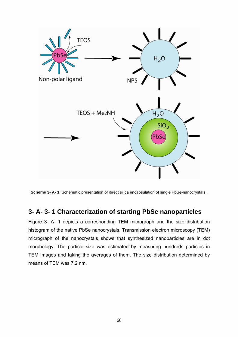
Scheme 3- A- 1. Schematic presentation of direct silica encapsulation of single PbSe-nanocrystals .
3- A- 3- 1 Characterization of starting PbSe nanoparticles Figure 3- A- 1 depicts a corresponding TEM micrograph and the size distribution
histogram of the native PbSe nanocrystals. Transmission electron microscopy (TEM)
micrograph of the nanocrystals shows that synthesized nanoparticles are in dot
morphology. The particle size was estimated by measuring hundreds particles in
TEM images and taking the averages of them. The size distribution determined by
means of TEM was 7.2 nm.
68
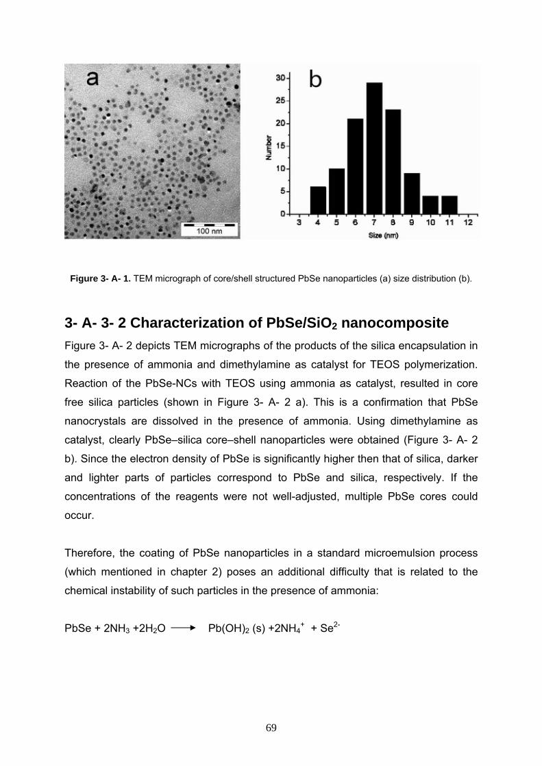
Figure 3- A- 1. TEM micrograph of core/shell structured PbSe nanoparticles (a) size distribution (b).
3- A- 3- 2 Characterization of PbSe/SiO2 nanocomposite Figure 3- A- 2 depicts TEM micrographs of the products of the silica encapsulation in
the presence of ammonia and dimethylamine as catalyst for TEOS polymerization.
Reaction of the PbSe-NCs with TEOS using ammonia as catalyst, resulted in core
free silica particles (shown in Figure 3- A- 2 a). This is a confirmation that PbSe
nanocrystals are dissolved in the presence of ammonia. Using dimethylamine as
catalyst, clearly PbSe–silica core–shell nanoparticles were obtained (Figure 3- A- 2
b). Since the electron density of PbSe is significantly higher then that of silica, darker
and lighter parts of particles correspond to PbSe and silica, respectively. If the
concentrations of the reagents were not well-adjusted, multiple PbSe cores could
occur.
Therefore, the coating of PbSe nanoparticles in a standard microemulsion process
(which mentioned in chapter 2) poses an additional difficulty that is related to the
chemical instability of such particles in the presence of ammonia:
PbSe + 2NH +2H O Pb(OH) (s) +2NH + Se3 2 2 4+ 2-
69
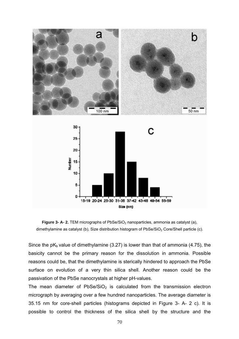
Figure 3- A- 2. TEM micrographs of PbSe/SiO2 nanoparticles, ammonia as catalyst (a),
dimethylamine as catalyst (b), Size distribution histogram of PbSe/SiO2 Core/Shell particle (c).
Since the pKb value of dimethylamine (3.27) is lower than that of ammonia (4.75), the
basicity cannot be the primary reason for the dissolution in ammonia. Possible
reasons could be, that the dimethylamine is sterically hindered to approach the PbSe
surface on evolution of a very thin silica shell. Another reason could be the
passivation of the PbSe nanocrystals at higher pH-values.
The mean diameter of PbSe/SiO2 is calculated from the transmission electron
micrograph by averaging over a few hundred nanoparticles. The average diameter is
35.15 nm for core-shell particles (histograms depicted in Figure 3- A- 2 c). It is
possible to control the thickness of the silica shell by the structure and the
70
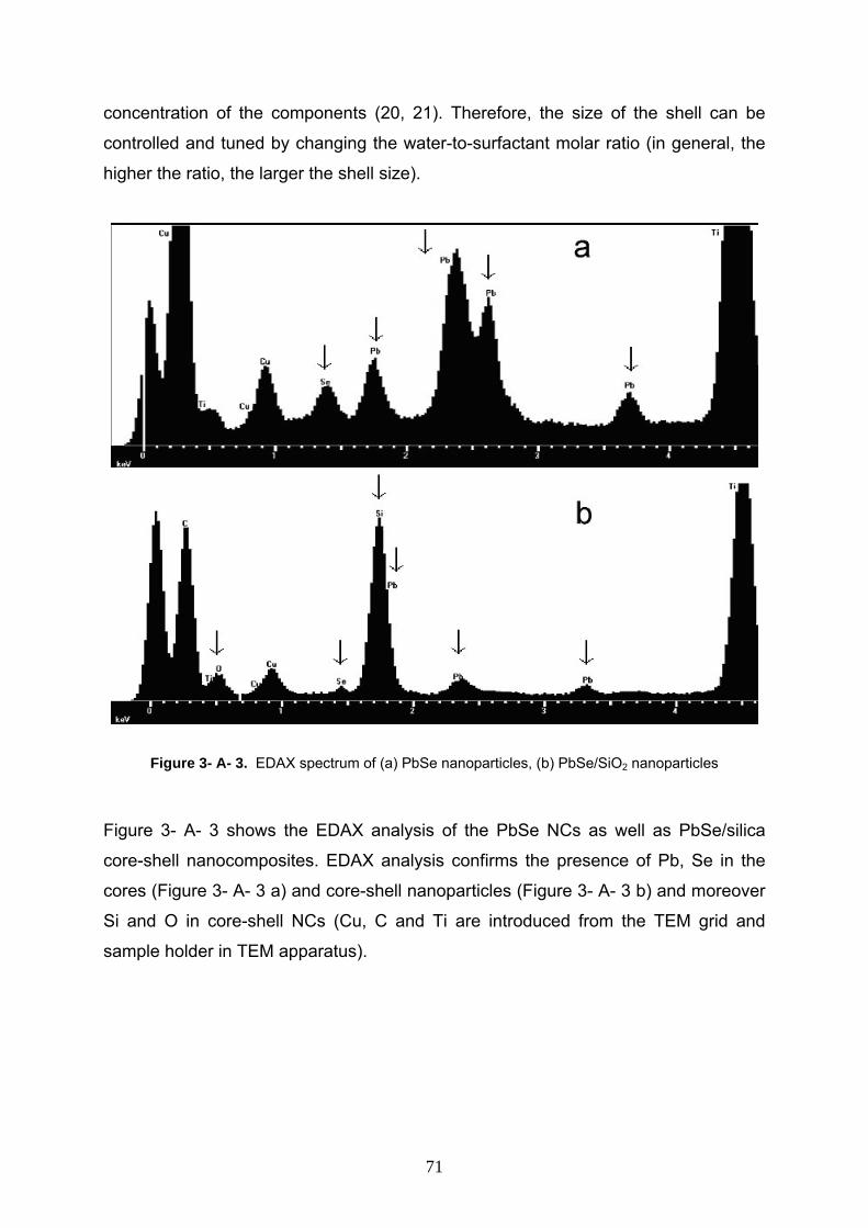
concentration of the components (20, 21). Therefore, the size of the shell can be
controlled and tuned by changing the water-to-surfactant molar ratio (in general, the
higher the ratio, the larger the shell size).
Figure 3- A- 3. EDAX spectrum of (a) PbSe nanoparticles, (b) PbSe/SiO2 nanoparticles
Figure 3- A- 3 shows the EDAX analysis of the PbSe NCs as well as PbSe/silica
core-shell nanocomposites. EDAX analysis confirms the presence of Pb, Se in the
cores (Figure 3- A- 3 a) and core-shell nanoparticles (Figure 3- A- 3 b) and moreover
Si and O in core-shell NCs (Cu, C and Ti are introduced from the TEM grid and
sample holder in TEM apparatus).
71
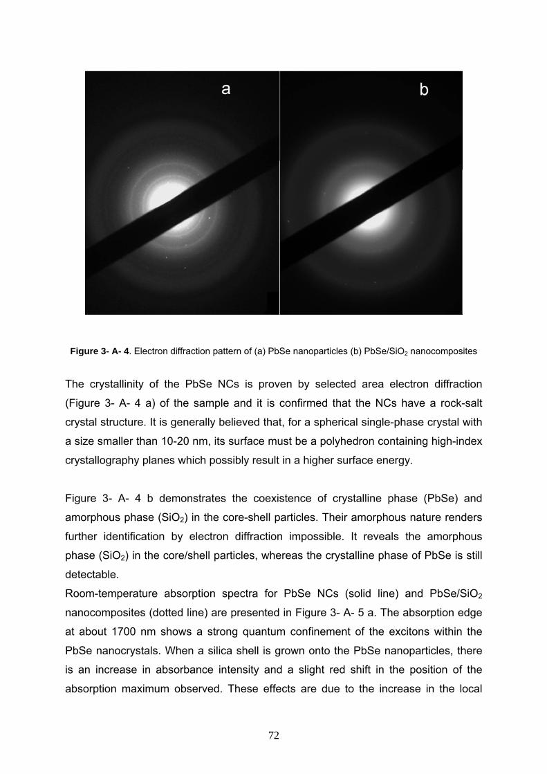
Figure 3- A- 4. Electron diffraction pattern of (a) PbSe nanoparticles (b) PbSe/SiO2 nanocomposites
The crystallinity of the PbSe NCs is proven by selected area electron diffraction
(Figure 3- A- 4 a) of the sample and it is confirmed that the NCs have a rock-salt
crystal structure. It is generally believed that, for a spherical single-phase crystal with
a size smaller than 10-20 nm, its surface must be a polyhedron containing high-index
crystallography planes which possibly result in a higher surface energy.
Figure 3- A- 4 b demonstrates the coexistence of crystalline phase (PbSe) and
amorphous phase (SiO2) in the core-shell particles. Their amorphous nature renders
further identification by electron diffraction impossible. It reveals the amorphous
phase (SiO2) in the core/shell particles, whereas the crystalline phase of PbSe is still
detectable.
Room-temperature absorption spectra for PbSe NCs (solid line) and PbSe/SiO2
nanocomposites (dotted line) are presented in Figure 3- A- 5 a. The absorption edge
at about 1700 nm shows a strong quantum confinement of the excitons within the
PbSe nanocrystals. When a silica shell is grown onto the PbSe nanoparticles, there
is an increase in absorbance intensity and a slight red shift in the position of the
absorption maximum observed. These effects are due to the increase in the local
72
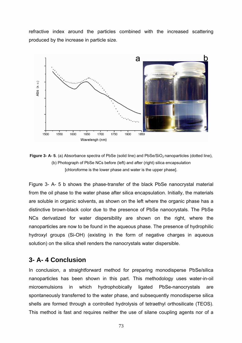
refractive index around the particles combined with the increased scattering
produced by the increase in particle size.
Figure 3- A- 5. (a) Absorbance spectra of PbSe (solid line) and PbSe/SiO2 nanoparticles (dotted line),
(b) Photograph of PbSe NCs before (left) and after (right) silica encapsulation
[chloroforme is the lower phase and water is the upper phase].
Figure 3- A- 5 b shows the phase-transfer of the black PbSe nanocrystal material
from the oil phase to the water phase after silica encapsulation. Initially, the materials
are soluble in organic solvents, as shown on the left where the organic phase has a
distinctive brown-black color due to the presence of PbSe nanocrystals. The PbSe
NCs derivatized for water dispersibility are shown on the right, where the
nanoparticles are now to be found in the aqueous phase. The presence of hydrophilic
hydroxyl groups (Si-OH) (existing in the form of negative charges in aqueous
solution) on the silica shell renders the nanocrystals water dispersible.
3- A- 4 Conclusion In conclusion, a straightforward method for preparing monodisperse PbSe/silica
nanoparticles has been shown in this part. This methodology uses water-in-oil
microemulsions in which hydrophobically ligated PbSe-nanocrystals are
spontaneously transferred to the water phase, and subsequently monodisperse silica
shells are formed through a controlled hydrolysis of tetraethyl orthosilicate (TEOS).
This method is fast and requires neither the use of silane coupling agents nor of a
73
poorly reproducible precoating step with sodium silicate. The method could be
applied to a variety of semiconductor nanocrystals with sphere or rod shape and
there is no apparent limit to use the principles developed here for encapsulation of
any type of hydrophobic nanocrystals of semiconductors, metals, magnetic materials,
or oxides. The thin silica shell increases the mechanical stability, enables transfer
into polar solvents and functionalization, and thus has the potential for many new
applications.
74
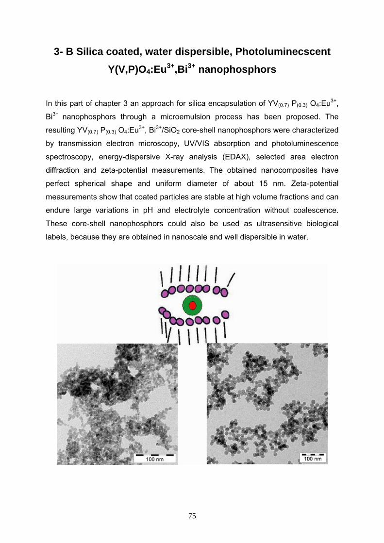
3- B Silica coated, water dispersible, Photoluminecscent Y(V,P)O4:Eu3+,Bi3+ nanophosphors
In this part of chapter 3 an approach for silica encapsulation of YV(0.7) P(0.3) O4:Eu3+,
Bi3+ nanophosphors through a microemulsion process has been proposed. The
resulting YV(0.7) P(0.3) O4:Eu3+, Bi3+/SiO2 core-shell nanophosphors were characterized
by transmission electron microscopy, UV/VIS absorption and photoluminescence
spectroscopy, energy-dispersive X-ray analysis (EDAX), selected area electron
diffraction and zeta-potential measurements. The obtained nanocomposites have
perfect spherical shape and uniform diameter of about 15 nm. Zeta-potential
measurements show that coated particles are stable at high volume fractions and can
endure large variations in pH and electrolyte concentration without coalescence.
These core-shell nanophosphors could also be used as ultrasensitive biological
labels, because they are obtained in nanoscale and well dispersible in water.
75
3- B- 1 Introduction As complementary example to more prove the generality of silica encapsulation
process, YVO4:Eu3+ nanoparticles have been considered in this part of chapter three.
In recent years, rare-earth-doped nanocrystalline phosphors have attracted great
interest. The main work concerns the synthesis and the spectrum changes of
nanoparticles. Among the different host materials researched, much attention has
been given to Yttrium orthovanadate (YVO4) which is an important oxide in materials
science and technology. YVO4 has been widely used as a host lattice for lanthanide
ions to produce phosphors emitting a variety of colors. It has been used as polarizer
and laser host material in its single crystalline form, as a red phosphor (doped with
Eu3+ ions) in cathode ray tubes (CRTs), high pressure mercury lamp, thermographic
sensing, thermoluminescence, fluorescent lamps and colour television in its powder
form. Bulk YVO4:Eu3+ is a highly photoluminescent material with 70%
photoluminescence quantum yield and has a strong luminescence efficiency on
electron beam excitation. This phosphorous is recently attracting the attention for
application to field emission display (FED) devices due to its sulfur-free composition
and fabrication of thin film in relatively low temperature. It has been reported that
when the Eu ion is located in a host lattice lacking inversion symmetry such as YVO4,
luminescent properties of Eu activated phosphor are affected by the crystal symmetry
of the Eu site. As a result, YVO4: Eu phosphor shows good color purity (22-26).
Different methods have been used to prepare YVO4:Eu since it was introduced by
Levine and Pallia, for example, a high temperature solid state method, a hydrolyzed
colloid reaction technique, solution combination methods, hydrothermal methods, a
urea precipitation technique and microemulsion-mediated synthetic processes. The
preparation methods for mixed crystals like Y(V,P)O4:Eu3+ as used in this chapter is
similar to the pure vanadates, the codoping with Bi was done in order to slightly
shift the excitation wavelength to the red. Besides a very small brad banded
background fluorescence there is no qualitative change in the emission
characteristics of the Eu ions in the nanocrystal and the advantage of exchanging V
by P is that it has a hybrid between phosphates and vanadates. Thus the possibilities
to couple other molecules to the nanoparticles are broader than for a pure vanadate.
The optical properties remain unchanged by replacing V by P
3+
3+
(27-30).
76
To motivate the application and functionalization of these nanoparticles, especially in
biological direction, silica shell could apply on the surface of these particles. The
amphiphilic properties of silica, especially in aqueous media, provide the particles
with an increased colloidal stability. This enables concentrated dispersions to be
prepared, with higher ionic strength, temperature, solvent polarity, and it can endure
large variations in pH, compared to other colloidal nanoparticles. Moreover, the
surface is usually terminated with silanol groups which can be functionalized with
well-known methods. One potential application for such nanoparticles could be a
luminescent biomedical targeting/drug-delivery system (31-34).
However, so far core-shell nanophosphors of the type YV(0.7)P(0.3)O4:Eu3+,Bi3+/SiO2
have not been reported in the literature. Guided by these considerations, I reported
an alternative approach for the preparation of nanocomposites composed of SiO2
with YV(0.7)P(0.3)O4:Eu3+,Bi3+ nanometer sized cores inside a microemulsion reaction
matrix. The process is performed in conjunction with the hydrolysis of organometallic
precursors such as tetraethoxysilane (TEOS), followed by condensation in the water
nanodroplets to form a coating on the NC’s within reverse micelle structures. The
procedure yields NC’s encapsulated in a silica shell with a diameter of about 15 nm.
3- B- 2 Experimental section 3- B- 2- 1 Syntheses of YV(0.7) P(0.3) O4:Eu3+, Bi3+
nanocrystals YCl3 . 6H2O (2.7319 g, 9 mmol), BiCl3 . H2O (100 mg, 0.3 mmol) and EuCl3 . 6H2O
(257 mg, 0.7 mmol) were dissolved in 57 mL ethylene glycol. In a second flask
Na2VO4 (1.283 g, 7 mmol) and K3PO4 . H2O (692 mg, 3 mmol) were dissolved in 4
mol H2O followed by adding 43 mL ethylene glycol thereto. The resulting solution is
added slowly at room temperature under vigorous stirring to the above metal salts
solution. Thereafter, 100 mL water is added and the resulting transparent yellow
reaction solution is transferred to an autoclave. Autoclaving (P= ca. 15 bar by air
flow) is conducted for 2 h at 200o C. After cooling 300 mL acetone are added to the
suspension and the resulting precipitate is centrifuged, washed twice with acetone
and dried in vacuum. Yield: 2.037 g (99% of theoretical value).
77
3- B- 2- 2 Silica encapsulation of YV(0.7) P(0.3) O4:Eu3+, Bi3+
nanocrystals Typically, a water-in-oil microemulsion was prepared by mixing 15 mL cyclohexane,
4.100 mL NP-5 (Polyethylene glycol nonylphenyl ether), 1 mL stock-solution (1.74 ×
10−6 mol/L) of NC’s in pure water to flask under vigorous stirring, and 120 µL TEOS
(tetraethyl orthosilicate) was then added as a precursor for silica formation, 30 min
after the micro-emulsion system was formed, 100µL ammonia aqueous solution
(33wt %) was introduced to initiate the polymerization process. The reaction was
allowed to continue for 24 h at room temperature. After the reaction was complete,
the core-shell NCs were isolated from the microemulsion using acetone, then they
were centrifuged, and, finally, a surfactant and not reacted molecules were washed
out from the resultant precipitate of YV (0.7) P (0.3) O4:Eu3+, Bi3+/SiO2 particles,
sequentially, with 1-butanol, 1-propanol, ethanol and water. The ultrasonic treatment
was a necessary step of the washing out procedure, to completely disperse the
precipitate in the solvent and to remove the adsorbed molecules from the surface of
NCs.
3- B- 2- 3 Characterization methods To determine the size and shape of as-prepared and silica encapsulated NC’s, I used
the Transmission Electron Microscope (TEM), Model Zeiss LEO 912 Omega, which
operated at 120 kV. The samples for the TEM study were prepared by drop casting of
colloidal solutions of NCs onto carbon films, supported by a Cu grid. The room-
temperature absorption and luminescent measurements were performed using
colloidal solutions of NCs with the UV-visible J&M TIDAS diode array spectrometer.
The dynamic and electrophoretic light backscattering experiments were carried out
with a Nanosizer ZS (Malvern Instruments, Malvern, UK).
Crystalline phases of the samples were analyzed by XRD Siemens D5000 using Cu K radiationα (λ = 1.5406 A°).
78
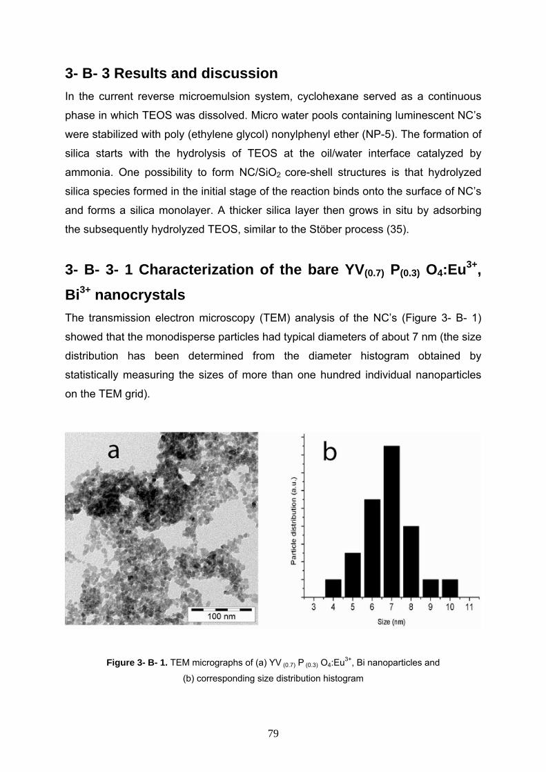
3- B- 3 Results and discussion In the current reverse microemulsion system, cyclohexane served as a continuous
phase in which TEOS was dissolved. Micro water pools containing luminescent NC’s
were stabilized with poly (ethylene glycol) nonylphenyl ether (NP-5). The formation of
silica starts with the hydrolysis of TEOS at the oil/water interface catalyzed by
ammonia. One possibility to form NC/SiO2 core-shell structures is that hydrolyzed
silica species formed in the initial stage of the reaction binds onto the surface of NC’s
and forms a silica monolayer. A thicker silica layer then grows in situ by adsorbing
the subsequently hydrolyzed TEOS, similar to the Stöber process (35).
3- B- 3- 1 Characterization of the bare YV(0.7) P(0.3) O4:Eu3+, Bi3+ nanocrystals The transmission electron microscopy (TEM) analysis of the NC’s (Figure 3- B- 1)
showed that the monodisperse particles had typical diameters of about 7 nm (the size
distribution has been determined from the diameter histogram obtained by
statistically measuring the sizes of more than one hundred individual nanoparticles
on the TEM grid).
Figure 3- B- 1. TEM micrographs of (a) YV (0.7) P (0.3) O4:Eu3+, Bi nanoparticles and
(b) corresponding size distribution histogram
79
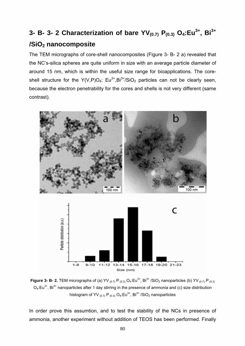
3- B- 3- 2 Characterization of bare YV(0.7) P(0.3) O4:Eu3+, Bi3+
/SiO2 nanocomposite The TEM micrographs of core-shell nanocomposites (Figure 3- B- 2 a) revealed that
the NC’s-silica spheres are quite uniform in size with an average particle diameter of
around 15 nm, which is within the useful size range for bioapplications. The core-
shell structure for the Y(V,P)O4: Eu3+,Bi3+/SiO2 particles can not be clearly seen,
because the electron penetrability for the cores and shells is not very different (same
contrast).
Figure 3- B- 2. TEM micrographs of (a) YV (0.7) P (0.3) O4:Eu3+, Bi3+ /SiO2 nanoparticles (b) YV (0.7) P (0.3)
O4:Eu3+, Bi3+ nanoparticles after 1 day stirring in the presence of ammonia and (c) size distribution
histogram of YV (0.7) P (0.3) O4:Eu3+, Bi3+ /SiO2 nanoparticles
In order prove this assumtion, and to test the stability of the NCs in presence of
ammonia, another experiment without addition of TEOS has been performed. Finally
80
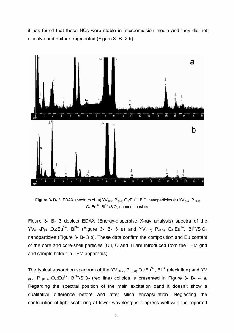
it has found that these NCs were stable in microemulsion media and they did not
dissolve and neither fragmented (Figure 3- B- 2 b).
Figure 3- B- 3. EDAX spectrum of (a) YV (0.7) P (0.3) O4:Eu3+, Bi3+ nanoparticles (b) YV (0.7) P (0.3)
O4:Eu3+, Bi3+ /SiO2 nanocomposites.
Figure 3- B- 3 depicts EDAX (Energy-dispersive X-ray analysis) spectra of the
YV(0.7)P(0.3)O4:Eu3+, Bi3+ (Figure 3- B- 3 a) and YV(0.7) P(0.3) O4:Eu3+, Bi3+/SiO2
nanoparticles (Figure 3- B- 3 b). These data confirm the composition and Eu content
of the core and core-shell particles (Cu, C and Ti are introduced from the TEM grid
and sample holder in TEM apparatus).
The typical absorption spectrum of the YV (0.7) P (0.3) O4:Eu3+, Bi3+ (black line) and YV
(0.7) P (0.3) O4:Eu3+, Bi3+/SiO2 (red line) colloids is presented in Figure 3- B- 4 a.
Regarding the spectral position of the main excitation band it doesn’t show a
qualitative difference before and after silica encapsulation. Neglecting the
contribution of light scattering at lower wavelengths it agrees well with the reported
81
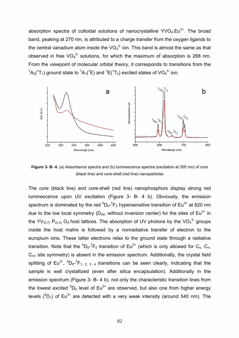
absorption spectra of colloidal solutions of nanocrystalline YVO4:Eu3+. The broad
band, peaking at 270 nm, is attributed to a charge transfer from the oxygen ligands to
the central vanadium atom inside the VO43- ion. This band is almost the same as that
observed in free VO43- solutions, for which the maximum of absorption is 268 nm.
From the viewpoint of molecular orbital theory, it corresponds to transitions from the 1A2(1T1) ground state to 1A1(1E) and 1E(1T2) excited states of VO4
3- ion.
Figure 3- B- 4. (a) Absorbance spectra and (b) luminescence spectra (excitation at 305 nm) of core
(black line) and core-shell (red line) nanoparticles
The core (black line) and core-shell (red line) nanophosphors display strong red
luminescence upon UV excitation (Figure 3- B- 4 b). Obviously, the emission
spectrum is dominated by the red 5D0-7F2 hypersensitive transition of Eu3+ at 620 nm
due to the low local symmetry (D2d, without inversion center) for the sites of Eu3+ in
the YV(0.7) P(0.3) O4 host lattices. The absorption of UV photons by the VO43- groups
inside the host matrix is followed by a nonradiative transfer of electron to the
europium ions. These latter electrons relax to the ground state through a radiative
transition. Note that the 5D0-7F0 transition of Eu3+ (which is only allowed for Cs, Cn,
CnV site symmetry) is absent in the emission spectrum. Additionally, the crystal field
splitting of Eu3+, 5D0-7F1, 2, 3, 4 transitions can be seen clearly, indicating that the
sample is well crystallized (even after silica encapsulation). Additionally in the
emission spectrum (Figure 3- B- 4 b), not only the characteristic transition lines from
the lowest excited 5D0 level of Eu3+ are observed, but also one from higher energy
levels (5D1) of Eu3+ are detected with a very weak intensity (around 540 nm). The
82
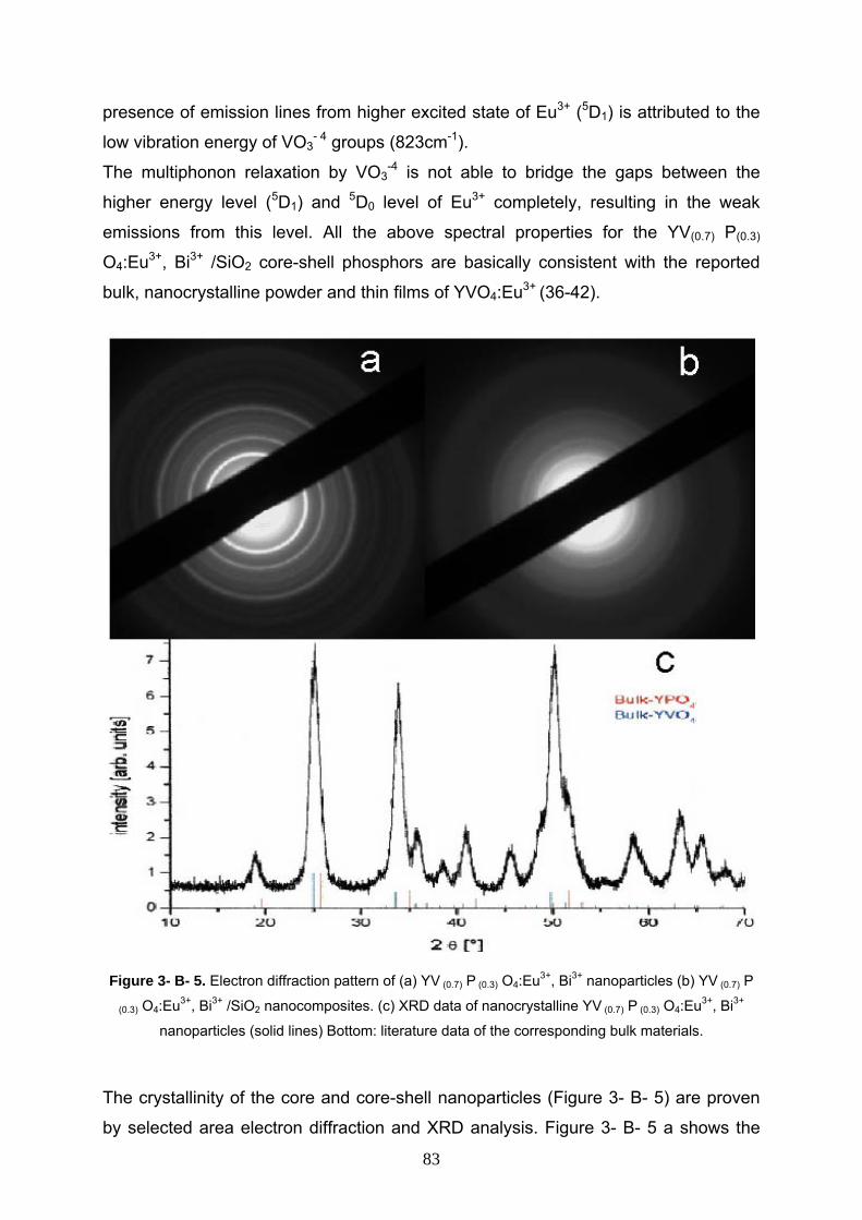
presence of emission lines from higher excited state of Eu3+ (5D1) is attributed to the
low vibration energy of VO3- 4 groups (823cm-1).
The multiphonon relaxation by VO3-4 is not able to bridge the gaps between the
higher energy level (5D1) and 5D0 level of Eu3+ completely, resulting in the weak
emissions from this level. All the above spectral properties for the YV(0.7) P(0.3)
O4:Eu3+, Bi3+ /SiO2 core-shell phosphors are basically consistent with the reported
bulk, nanocrystalline powder and thin films of YVO4:Eu3+ (36-42).
Figure 3- B- 5. Electron diffraction pattern of (a) YV (0.7) P (0.3) O4:Eu3+, Bi3+ nanoparticles (b) YV (0.7) P
(0.3) O4:Eu3+, Bi3+ /SiO2 nanocomposites. (c) XRD data of nanocrystalline YV (0.7) P (0.3) O4:Eu3+, Bi3+
nanoparticles (solid lines) Bottom: literature data of the corresponding bulk materials. The crystallinity of the core and core-shell nanoparticles (Figure 3- B- 5) are proven
by selected area electron diffraction and XRD analysis. Figure 3- B- 5 a shows the
83
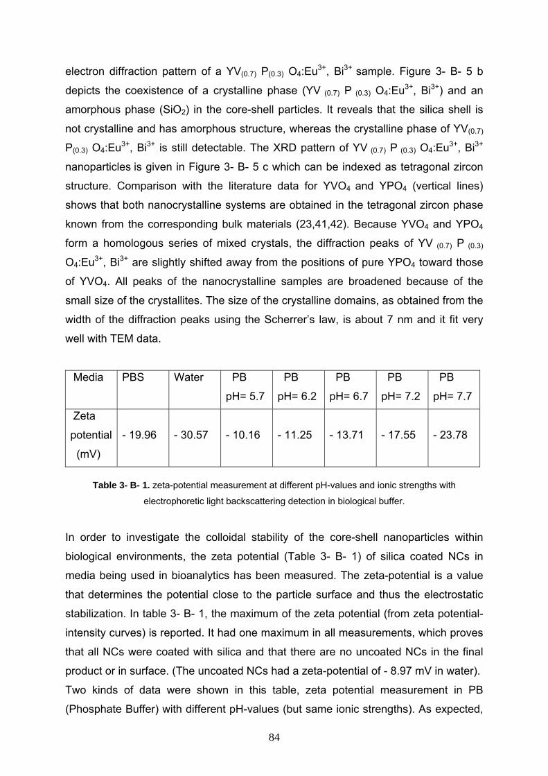
electron diffraction pattern of a YV(0.7) P(0.3) O4:Eu3+, Bi3+ sample. Figure 3- B- 5 b
depicts the coexistence of a crystalline phase (YV (0.7) P (0.3) O4:Eu3+, Bi3+) and an
amorphous phase (SiO2) in the core-shell particles. It reveals that the silica shell is
not crystalline and has amorphous structure, whereas the crystalline phase of YV(0.7)
P(0.3) O4:Eu3+, Bi3+ is still detectable. The XRD pattern of YV (0.7) P (0.3) O4:Eu3+, Bi3+
nanoparticles is given in Figure 3- B- 5 c which can be indexed as tetragonal zircon
structure. Comparison with the literature data for YVO4 and YPO4 (vertical lines)
shows that both nanocrystalline systems are obtained in the tetragonal zircon phase
known from the corresponding bulk materials (23,41,42). Because YVO4 and YPO4
form a homologous series of mixed crystals, the diffraction peaks of YV (0.7) P (0.3)
O4:Eu3+, Bi3+ are slightly shifted away from the positions of pure YPO4 toward those
of YVO4. All peaks of the nanocrystalline samples are broadened because of the
small size of the crystallites. The size of the crystalline domains, as obtained from the
width of the diffraction peaks using the Scherrer’s law, is about 7 nm and it fit very
well with TEM data.
Media PBS Water PB
pH= 5.7
PB
pH= 6.2 PB
pH= 6.7 PB
pH= 7.2 PB
pH= 7.7
Zeta
potential
(mV)
- 19.96
- 30.57
- 10.16
- 11.25
- 13.71
- 17.55
- 23.78
Table 3- B- 1. zeta-potential measurement at different pH-values and ionic strengths with
electrophoretic light backscattering detection in biological buffer.
In order to investigate the colloidal stability of the core-shell nanoparticles within
biological environments, the zeta potential (Table 3- B- 1) of silica coated NCs in
media being used in bioanalytics has been measured. The zeta-potential is a value
that determines the potential close to the particle surface and thus the electrostatic
stabilization. In table 3- B- 1, the maximum of the zeta potential (from zeta potential-
intensity curves) is reported. It had one maximum in all measurements, which proves
that all NCs were coated with silica and that there are no uncoated NCs in the final
product or in surface. (The uncoated NCs had a zeta-potential of - 8.97 mV in water). Two kinds of data were shown in this table, zeta potential measurement in PB
(Phosphate Buffer) with different pH-values (but same ionic strengths). As expected,
84
it was observed that the zeta-potential increased with increasing pH-value, due to
increasing deprotonation of the silica. The zeta-potential of the particles was found to
be higher in deionised water, because of the lower ionic strength. For comparison,
the zeta-potential was measured in phospate buffered saline (PBS, Fluka).
3- B- 4 Conclusion In summary, YV(0.7) P(0.3) O4:Eu3+, Bi3+
nanophosphors have been successfully coated
with thin SiO2 layers through a microemulsion process. The resulting YV(0.7) P(0.3)
O4:Eu3+, Bi3+/SiO2 core-shell nanophosphors were characterized by transmission
electron microscopy, UV/VIS absorption and photoluminescence spectroscopy,
energy-dispersive X-ray analysis (EDAX), selected area electron diffraction and zeta
potential measurements. All these techniques showed that the silica encapsulation
was successfully done and there are no un-shelled NCs in the final products. The
obtained core-shell nanophosphors have perfect spherical shape with narrow size
distribution (average size about 15 nm) and smooth surfaces.
The spectral properties of the core-shell nanophosphors are similar to those of the
reported bulk and nanocrystalline YVO4:Eu3+ phosphors. The obvious advantages of
a silica surface over normal double layer formation is, that the coated particles are
stable at high volume fractions and can endure large variations in pH and electrolyte
concentration without coalescing, an essential prerequisite for commercial process
development. These core-shell nanophosphors could also be useful as means for
ultrasensitive biological labels because they are well dispersable in water, providing
important anchor groups (silanol) for the biofunctionalization and therefore have a
high potential for the development to specific biolabels.
85
References 1- D. V. Talapin, C. B. Murray, Science 2005, 310, 86.
2- A. J. Nozik, Inorg. Chem. 2005, 44, 6893.
3- B. L. Wehrenberg, P. Guyot-Sionnest, J. Am. Chem. Soc., 2003, 125, 7806.
4- R. D. Schaller, M. A. Petruska, V. I. Klimov, J. Phys. Chem. B, 2003, 107,13765.
5- I. Kang, F. W. Wise, J. Opt. Soc. Am. B, 1997, 14, 1632.
6- Z. Hu, M. D. Fischbein, M. Drndic, Nano Lett., 2005, 5, 1463. 7- A. Sashchiuk, L. Amirav, M. Bashouti, M. Krueger, U. Sivan, E. Lifshitz, Nano
Lett.,2004, 4, 159.
8- R. Kerner, O. Palchik, A. Gedanken, Chem. Mater. 2001, 13, 1413.
9- J. J. Zhu, H. Wang, S. Xu, H. Y. Chen, Langmuir 2002, 18, 3306.
10- W. Y. William, C. F. Joshua, S. S. Bertram, L. C. Vicki, Chem. Mater. 2004, 16, 3318. 11- C. B. Murray, S. Sun, W. Gaschler, H. Doyle, T. A. Betley, C. R. Kagan, IBM J.
Res. DeV. 2001, 45, 47.
12- E. Lifshitz, M. Bashouti, V. Kloper, A. Kigel, M. S. Eisen, S. Berger, Nano Lett.
2003, 3, 857.
13- W. Lu, P. Gao, W. B. Jian, Z. L. Wang, J. Fang, J. Am. Chem. Soc. 2004, 126,
14816.
14- A. Sashchiuk, L. Langol, R. Chaim, E. Lifshitz, J. Cryst. Growth 2002, 240, 431.
15- A. S. Ethiraj, N. Hebalkarand, S. K. Kulkarni, J. Chem. Phys. 2003, 118, 8945.
16- S. Kim, B. Fisher, H. J. Eisler, M. Bawendi, J. Am. Chem. Soc. 2003, 125, 11466.
17- F. Chen, K. L. Stokes, W. Zhou, J. Fang, C. B. Murray, Mater. Res.Soc. Symp.
Proc. 2002, 691, 359.
18- K. S. Cho, D. V. Talapin, W. Gaschler, C. B. Murray, J. Am. Chem.Soc. 2005,
127, 7140.
19- W. Lu, J. Fang, Y. Ding, Z. L. Wang, J. Phys. Chem. B 2005, 109, 19219.
20- S. Santra, R. Tapec, N. Theodoropoulou, J. Dobson, A. Hebard, W. Tan,
Langmuir 2001, 17, 2900.
21- P. A. Dresco, V. S. Zaitsev, R. J. Gambino, B. Chu, Langmuir 1999, 15, 1945.
22- L. Yanhong, H. Guangyan, J. Solid. State. Chem., 2005, 178, 645.
23- H. Y. Xu, H.Wang, T. N. Jin, H. Yan, Nanotechnology, 2005, 16, 65.
24- J. H. Kang, M. Nazarov, W. B. Im, J. Y. Kim, D. Y. Jeon, J. Vac. Sci. Technol. B,
2005, 232, 843. 25- C. Jia, L. Sun, F. Luo, X. Jiang, L. Wei, C. Yan, Appl. Phys. Lett, 2004, 84, 5305.
86
26- D. Kim, W. Kang, Bull. Korean Chem. Soc. 2004, 25, 1859. 27- H. Zhang, X. Fu, S. Niu, G. Sun, Q. Xin, J. Solid. State. Chem., 2004, 177, 2649.
28- A. Huignard, T. Gacoin, J. P. Boilot, Chem. Mater., 2000, 12, 1090.
29- A. Huignard, V. Buissette, A. C. Franville, T. Gacoin, J. P. Boilot, J. Phys. Chem.
B, 2003, 107, 6754.
30- Y.H. Zhou, J. Lin, Opt. Mater., 2005, 27, 1426.
31- S. Santra, H.Yang, D. Dutta, J. T. Stanley, P. H. Holloway, W. Tan, B. M.
Moudgil, R. A. Mericle, Chem. Commun., 2004, 2810.
32- M. Qhobosheane, S. Santra, P. Zhang, W. Tan, Analyst, 2001, 126, 1274.
33- T. Nann, P. Mulvaney, Angew. Chem. Int. Edit., 2004, 43, 5393.
34- X. Gao, K. M. K. Yu, K. Y. Tam, S. C. Tsang, Chem. Commun., 2003, 2998
35- W. Stöber, A. Fink, E. Bohn, J. Colloid Interface Sci., 1968, 26, 62.
36- J. H. Kang, W. B. Im, D. C. Lee, J. Y. Kim, D. Y. Jeon, Y. C. Kang, K. Y. Jung,
Solid. State. Commun., 2005, 133, 651.
37- C. H. Yan, L. D. Sun, C. S. Liao, Y. X. Zhang, Y. Q. Lu, S. H. Huang, S. Z. Lu,
Appl. Phys. Lett., 2003, 82, 3511.
38- A. Huignard, V. Buissette, G. Laurent, T. Gacoin, J.P. Boilot, Chem. Mater., 2002, 14, 2264.
39- A. Huignard, T. Gacoin, J. P. Boilot, Chem. Mater., 2000, 12, 1090.
40- K. Uematsu, K. Toda, M. Sato, J. Alloy. Compd., 2005, 389, 209.
41- K. Riwotzki, M. Haase, J. Phys. Chem. B, 1998, 102, 10129.
42- K. Riwotzki, M. Haase, J. Phys. Chem. B, 2001, 105, 12709.
87

Chapter four
More investigation on the silica encapsulation, functionalization and
characterization
88
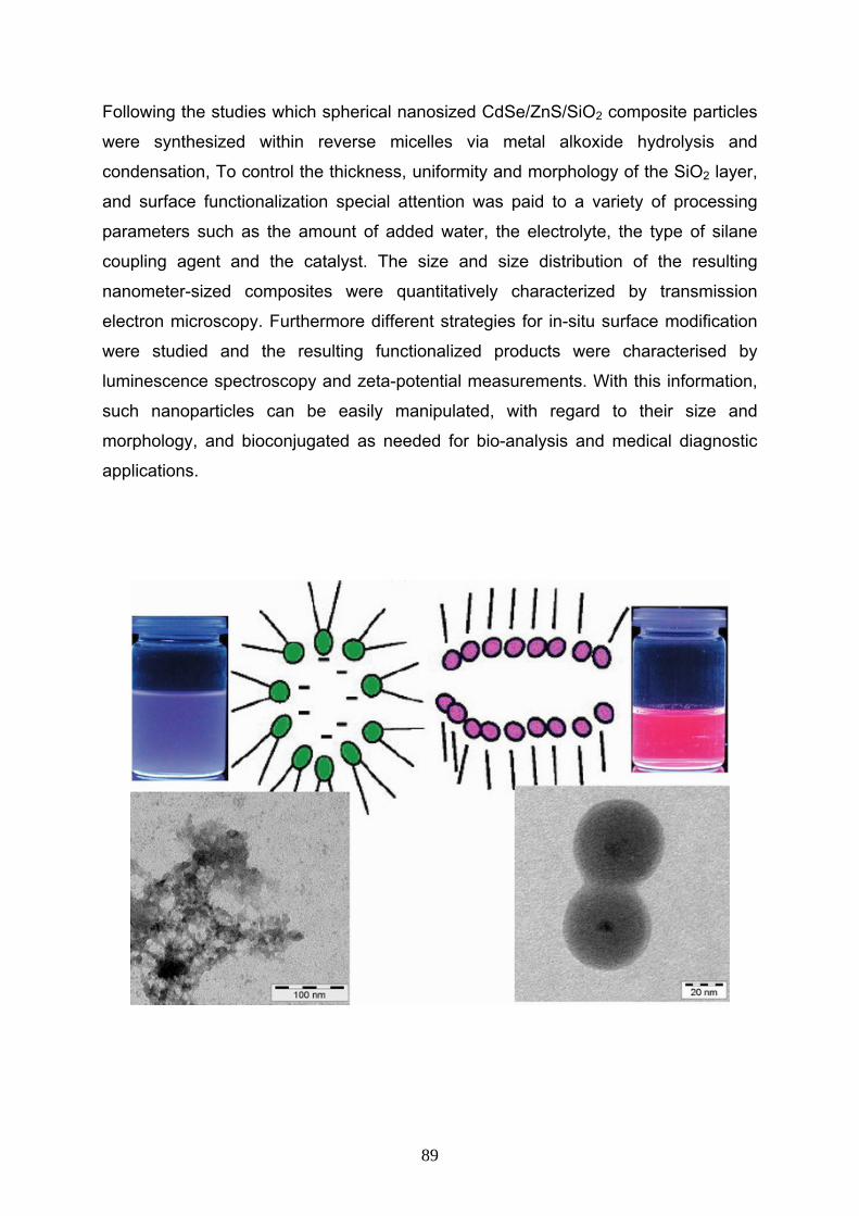
Following the studies which spherical nanosized CdSe/ZnS/SiO2 composite particles
were synthesized within reverse micelles via metal alkoxide hydrolysis and
condensation, To control the thickness, uniformity and morphology of the SiO2 layer,
and surface functionalization special attention was paid to a variety of processing
parameters such as the amount of added water, the electrolyte, the type of silane
coupling agent and the catalyst. The size and size distribution of the resulting
nanometer-sized composites were quantitatively characterized by transmission
electron microscopy. Furthermore different strategies for in-situ surface modification
were studied and the resulting functionalized products were characterised by
luminescence spectroscopy and zeta-potential measurements. With this information,
such nanoparticles can be easily manipulated, with regard to their size and
morphology, and bioconjugated as needed for bio-analysis and medical diagnostic
applications.
89
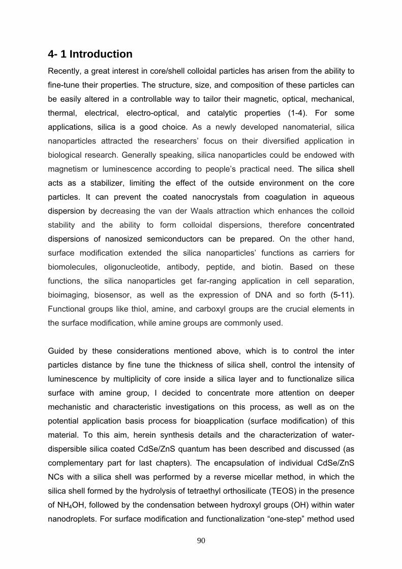
4- 1 Introduction Recently, a great interest in core/shell colloidal particles has arisen from the ability to
fine-tune their properties. The structure, size, and composition of these particles can
be easily altered in a controllable way to tailor their magnetic, optical, mechanical,
thermal, electrical, electro-optical, and catalytic properties (1-4). For some
applications, silica is a good choice. As a newly developed nanomaterial, silica
nanoparticles attracted the researchers’ focus on their diversified application in
biological research. Generally speaking, silica nanoparticles could be endowed with
magnetism or luminescence according to people’s practical need. The silica shell
acts as a stabilizer, limiting the effect of the outside environment on the core
particles. It can prevent the coated nanocrystals from coagulation in aqueous
dispersion by decreasing the van der Waals attraction which enhances the colloid
stability and the ability to form colloidal dispersions, therefore concentrated
dispersions of nanosized semiconductors can be prepared. On the other hand,
surface modification extended the silica nanoparticles’ functions as carriers for
biomolecules, oligonucleotide, antibody, peptide, and biotin. Based on these
functions, the silica nanoparticles get far-ranging application in cell separation,
bioimaging, biosensor, as well as the expression of DNA and so forth (5-11).
Functional groups like thiol, amine, and carboxyl groups are the crucial elements in
the surface modification, while amine groups are commonly used.
Guided by these considerations mentioned above, which is to control the inter
particles distance by fine tune the thickness of silica shell, control the intensity of
luminescence by multiplicity of core inside a silica layer and to functionalize silica
surface with amine group, I decided to concentrate more attention on deeper
mechanistic and characteristic investigations on this process, as well as on the
potential application basis process for bioapplication (surface modification) of this
material. To this aim, herein synthesis details and the characterization of water-
dispersible silica coated CdSe/ZnS quantum has been described and discussed (as
complementary part for last chapters). The encapsulation of individual CdSe/ZnS
NCs with a silica shell was performed by a reverse micellar method, in which the
silica shell formed by the hydrolysis of tetraethyl orthosilicate (TEOS) in the presence
of NH4OH, followed by the condensation between hydroxyl groups (OH) within water
nanodroplets. For surface modification and functionalization “one-step” method used
90
for introducing amine groups onto the nanoparticle surface, namely, by the hydrolysis
of silanes such as 3-aminopropyl-(triethoxyl)silane (APS) and tetraethyl orthosilicate
(TEOS) at the same time. A fundamental understanding of these parameters will
provide a solid foundation for the effective application of these nanocomposites in
different fields such as biology and medical diagnostics.
4- 2 Experimental section
4- 2- 1 Chemicals
All of the chemicals were used as received without further purification. Polyethylene
glycol nonylphenyl ether (Synperonic NP-5 from Fluka), sodium bis-(2-
ethylhexyl)sulfosuccinate (AOT, from Aldrich), polyethylene glycol tert-octylphenyl
ether (Triton X-100 from Sigma), sodium dodecyl sulfate (SDS from Aldrich),
Tetraethyl orthosilicate (TEOS from Fluka), 3-aminopropyltris(methyloxy)silane (APS
from Aldrich), 3- mercaptopropyltris(methyloxy)silane (MPS from Aldrich), ammonia
aqueous solution (33 wt %), dimethylamine (40 wt %), cyclohexane, acetone,
butanol, propanol, and ethanol from internal sources.
4- 2- 2 Preparation of CdSe/ZnS/SiO2 nanoparticles The CdSe/ZnS/SiO2 particles were prepared by means of modified water in oil
microemulsion method at room temperature according to chapter 2 in optimum
condition (experimental part of chapter 2, section 2-2-3).
4- 2- 3 Characterization methods The products were characterized by means of transmission electron microscopy
(TEM) and luminescence spectroscopy. TEM studies were carried out on a Zeiss
LEO 912 Omega instrument, operating at 120 kV. TEM specimens were made by
evaporating one drop of reaction solution onto carbon-coated copper grids. Grids
were blotted dry on filter paper and investigated without further treatment.
The room-temperature luminescence measurements were performed using colloidal
solutions of NCs with the UV-visible J&M TIDAS diode array spectrometer.
The zeta potential or the overall surface charge of nanoparticle samples in solution
was determined using a Nanosizer ZS (Malvern Instruments, Malvern, UK).
91
4- 3 Result and discussion 4- 3- 1 Characterization of CdSe/ZnS/SiO2 nanoparticles synthesized in optimum condition Figure 4- 1a depicts a transmission electron microscopy (TEM) micrograph of
CdSe/ZnS/SiO2 nanoparticles, which were synthesized with optimum conditions as
described in the experimental section. Since the electron density of CdSe/ZnS is
significantly higher, darker and lighter parts of particles correspond to CdSe/ZnS and
silica, respectively. The TEM micrograph shows, that each silica nanoparticle
contains one CdSe/ZnS core and final products are spherical in shape. The mean
diameter of the CdSe/ZnS/SiO2 nanocomposites was estimated from the
transmission electron micrograph by averaging over a few hundred nanoparticles.
The average diameter was 38 nm for core-shell particles (histogram depicted in
Figure 4- 1b).
Figure 4- 1. (a) TEM micrograph (b) Size distribution histogram of CdSe/ZnS/SiO2 nanoparticles
synthesized with optimum conditions.
The main source for observed aggregation (in all TEM results) is fusing after sphere
preparation in solution directly on the TEM grid, due to strong interparticle
interactions after solvent evaporation. This problem can be minimized by changing
the TEM grid surface from carbon-coated to carbon/Formvar-coated grids, which are
92
more hydrophilic. The latter grid surface attracts more strongly the silica spheres and
reduces their mobility once deposited.
4- 3- 2 Effect of different catalysts on the synthesis of CdSe/ZnS/SiO2 nanocomposites The effect of different catalysts on the synthesis of CdSe/ZnS/SiO2 nanocomposites
was presented in Figure 4- 2 which sodium hydroxide, dimethylamine, pyridine,
acetic acid has been used as substituted catalyst instead of ammonia (same
concentration of catalyse in every step has been used). As one can see the final
product from sodium hydroxide (Figure 4- 2.a) is a core-shell structure with irregular
shape: cores are not in the centre of the silica shells, the monodispersity is not
satisfying, and many core free silica particles were formed. The surfaces of silica
coated CdSe/ZnS in presence of dimethylamine as catalyst are rough (in comparison
with optimum condition where the surface of the silica particles was smooth) and the
monodispersity is acceptable. When the catalyst was changed to pyridine, acetic acid
or hydrochloric acid, the final product was of polymeric structure (TEM result from
HCl is not shown here).
93
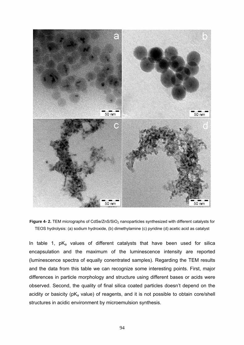
Figure 4- 2. TEM micrographs of CdSe/ZnS/SiO2 nanoparticles synthesized with different catalysts for
TEOS hydrolysis: (a) sodium hydroxide, (b) dimethylamine (c) pyridine (d) acetic acid as catalyst
In table 1, pKa values of different catalysts that have been used for silica
encapsulation and the maximum of the luminescence intensity are reported
(luminescence spectra of equally conentrated samples). Regarding the TEM results
and the data from this table we can recognize some interesting points. First, major
differences in particle morphology and structure using different bases or acids were
observed. Second, the quality of final silica coated particles doesn’t depend on the
acidity or basicity (pKa value) of reagents, and it is not possible to obtain core/shell
structures in acidic environment by microemulsion synthesis.
94
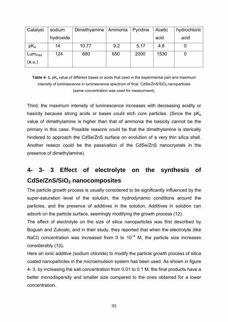
Catalyst sodium
hydroxide
Dimethyamine Ammonia Pyridine Acetic
acid
hydrochloric
acid
pKa 14 10.77 9.2 5.17 4.8 0
Lummax
(a.u.)
124 680 650 2000 1530 0
Table 4- 1. pKa value of different bases or acids that used in the experimental part and maximum
intensity of luminescence in luminescence spectrum of final CdSe/ZnS/SiO2 nanoparticles
(same concentration was used for measurment).
Third, the maximum intensity of luminescence increases with decreasing acidity or
basicity because strong acids or bases could etch core particles. (Since the pKa
value of dimethylamine is higher than that of ammonia the basicity cannot be the
primary in this case. Possible reasons could be that the dimethylamine is sterically
hindered to approach the CdSe/ZnS surface on evolution of a very thin silica shell.
Another reason could be the passivation of the CdSe/ZnS nanocrystals in the
presence of dimethylamine).
4- 3- 3 Effect of electrolyte on the synthesis of CdSe/ZnS/SiO2 nanocomposites
The particle growth process is usually considered to be significantly influenced by the
super-saturation level of the solution, the hydrodynamic conditions around the
particles, and the presence of additives in the solution. Additives in solution can
adsorb on the particle surface, seemingly modifying the growth process (12).
The effect of electrolyte on the size of silica nanoparticles was first described by
Bogush and Zukoski, and in their study, they reported that when the electrolyte (like
NaCl) concentration was increased from 0 to 10−4 M, the particle size increases
considerably (13). Here an ionic additive (sodium chloride) to modify the particle growth process of silica
coated nanoparticles in the microemulsion system has been used. As shown in figure
4- 3, by increasing the salt concentration from 0.01 to 0.1 M, the final products have a
better monodispersity and smaller size compared to the ones obtained for a lower
concentration.
95
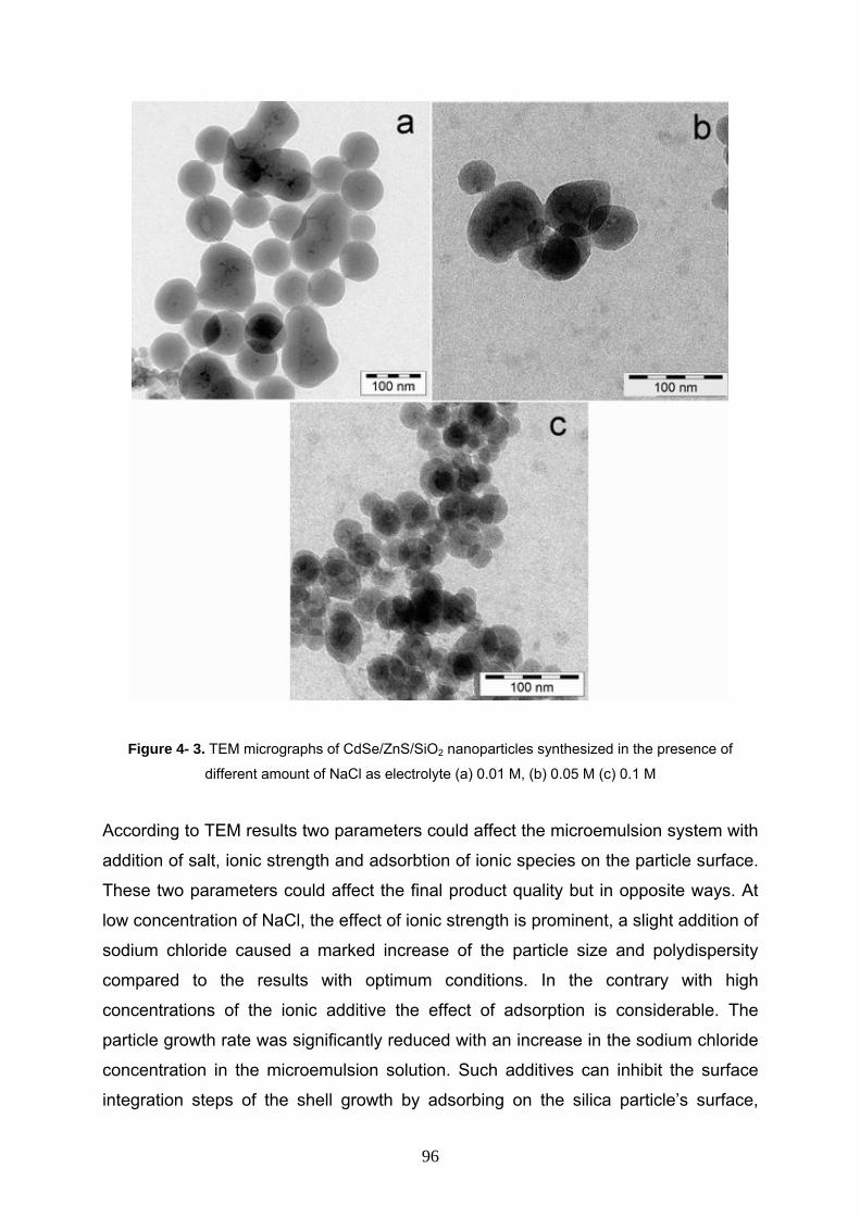
Figure 4- 3. TEM micrographs of CdSe/ZnS/SiO2 nanoparticles synthesized in the presence of
different amount of NaCl as electrolyte (a) 0.01 M, (b) 0.05 M (c) 0.1 M
According to TEM results two parameters could affect the microemulsion system with
addition of salt, ionic strength and adsorbtion of ionic species on the particle surface.
These two parameters could affect the final product quality but in opposite ways. At
low concentration of NaCl, the effect of ionic strength is prominent, a slight addition of
sodium chloride caused a marked increase of the particle size and polydispersity
compared to the results with optimum conditions. In the contrary with high
concentrations of the ionic additive the effect of adsorption is considerable. The
particle growth rate was significantly reduced with an increase in the sodium chloride
concentration in the microemulsion solution. Such additives can inhibit the surface
integration steps of the shell growth by adsorbing on the silica particle’s surface,
96
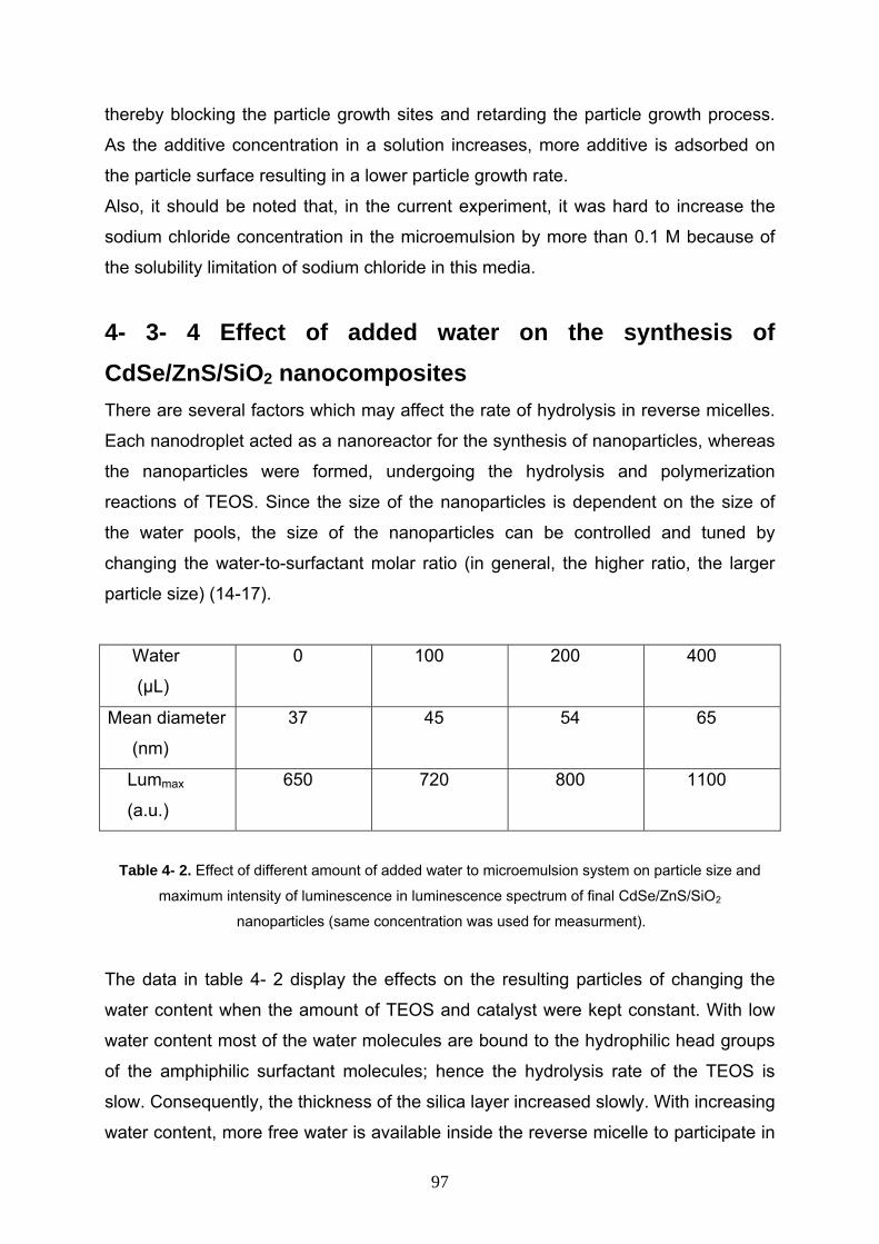
thereby blocking the particle growth sites and retarding the particle growth process.
As the additive concentration in a solution increases, more additive is adsorbed on
the particle surface resulting in a lower particle growth rate. Also, it should be noted that, in the current experiment, it was hard to increase the
sodium chloride concentration in the microemulsion by more than 0.1 M because of
the solubility limitation of sodium chloride in this media.
4- 3- 4 Effect of added water on the synthesis of CdSe/ZnS/SiO2 nanocomposites
There are several factors which may affect the rate of hydrolysis in reverse micelles.
Each nanodroplet acted as a nanoreactor for the synthesis of nanoparticles, whereas
the nanoparticles were formed, undergoing the hydrolysis and polymerization
reactions of TEOS. Since the size of the nanoparticles is dependent on the size of
the water pools, the size of the nanoparticles can be controlled and tuned by
changing the water-to-surfactant molar ratio (in general, the higher ratio, the larger
particle size) (14-17).
Water
(µL)
0 100 200 400
Mean diameter
(nm)
37 45 54 65
Lummax
(a.u.)
650 720 800 1100
Table 4- 2. Effect of different amount of added water to microemulsion system on particle size and
maximum intensity of luminescence in luminescence spectrum of final CdSe/ZnS/SiO2
nanoparticles (same concentration was used for measurment).
The data in table 4- 2 display the effects on the resulting particles of changing the
water content when the amount of TEOS and catalyst were kept constant. With low
water content most of the water molecules are bound to the hydrophilic head groups
of the amphiphilic surfactant molecules; hence the hydrolysis rate of the TEOS is
slow. Consequently, the thickness of the silica layer increased slowly. With increasing
water content, more free water is available inside the reverse micelle to participate in
97
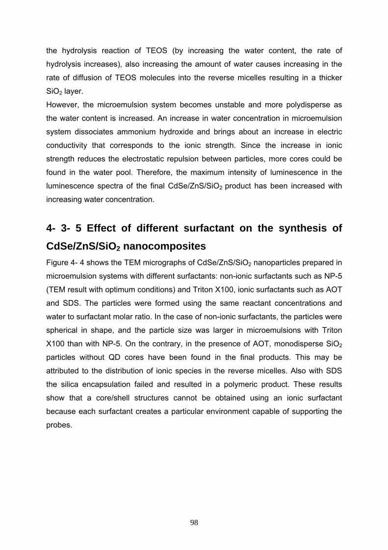
the hydrolysis reaction of TEOS (by increasing the water content, the rate of
hydrolysis increases), also increasing the amount of water causes increasing in the
rate of diffusion of TEOS molecules into the reverse micelles resulting in a thicker
SiO2 layer. However, the microemulsion system becomes unstable and more polydisperse as
the water content is increased. An increase in water concentration in microemulsion
system dissociates ammonium hydroxide and brings about an increase in electric
conductivity that corresponds to the ionic strength. Since the increase in ionic
strength reduces the electrostatic repulsion between particles, more cores could be
found in the water pool. Therefore, the maximum intensity of luminescence in the
luminescence spectra of the final CdSe/ZnS/SiO2 product has been increased with
increasing water concentration.
4- 3- 5 Effect of different surfactant on the synthesis of CdSe/ZnS/SiO2 nanocomposites
Figure 4- 4 shows the TEM micrographs of CdSe/ZnS/SiO2 nanoparticles prepared in
microemulsion systems with different surfactants: non-ionic surfactants such as NP-5
(TEM result with optimum conditions) and Triton X100, ionic surfactants such as AOT
and SDS. The particles were formed using the same reactant concentrations and
water to surfactant molar ratio. In the case of non-ionic surfactants, the particles were
spherical in shape, and the particle size was larger in microemulsions with Triton
X100 than with NP-5. On the contrary, in the presence of AOT, monodisperse SiO2
particles without QD cores have been found in the final products. This may be
attributed to the distribution of ionic species in the reverse micelles. Also with SDS
the silica encapsulation failed and resulted in a polymeric product. These results
show that a core/shell structures cannot be obtained using an ionic surfactant
because each surfactant creates a particular environment capable of supporting the
probes.
98
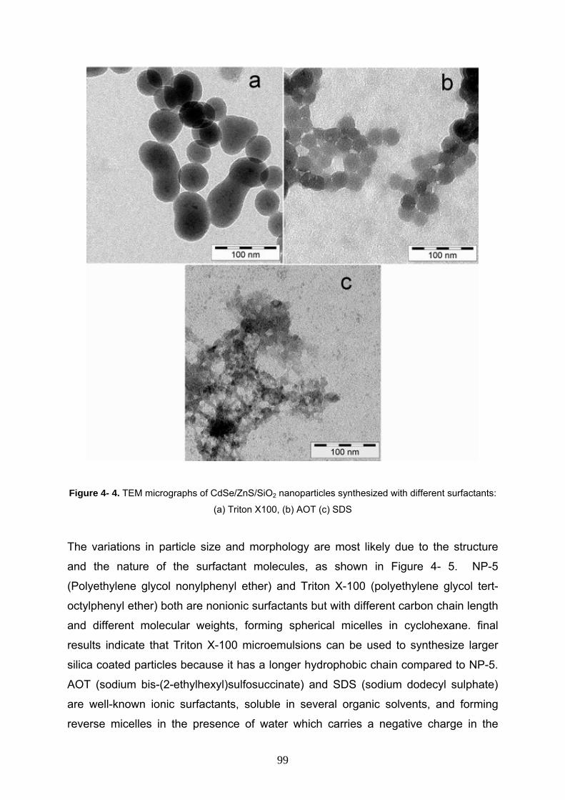
Figure 4- 4. TEM micrographs of CdSe/ZnS/SiO2 nanoparticles synthesized with different surfactants:
(a) Triton X100, (b) AOT (c) SDS
The variations in particle size and morphology are most likely due to the structure
and the nature of the surfactant molecules, as shown in Figure 4- 5. NP-5
(Polyethylene glycol nonylphenyl ether) and Triton X-100 (polyethylene glycol tert-
octylphenyl ether) both are nonionic surfactants but with different carbon chain length
and different molecular weights, forming spherical micelles in cyclohexane. final
results indicate that Triton X-100 microemulsions can be used to synthesize larger
silica coated particles because it has a longer hydrophobic chain compared to NP-5. AOT (sodium bis-(2-ethylhexyl)sulfosuccinate) and SDS (sodium dodecyl sulphate)
are well-known ionic surfactants, soluble in several organic solvents, and forming
reverse micelles in the presence of water which carries a negative charge in the
99
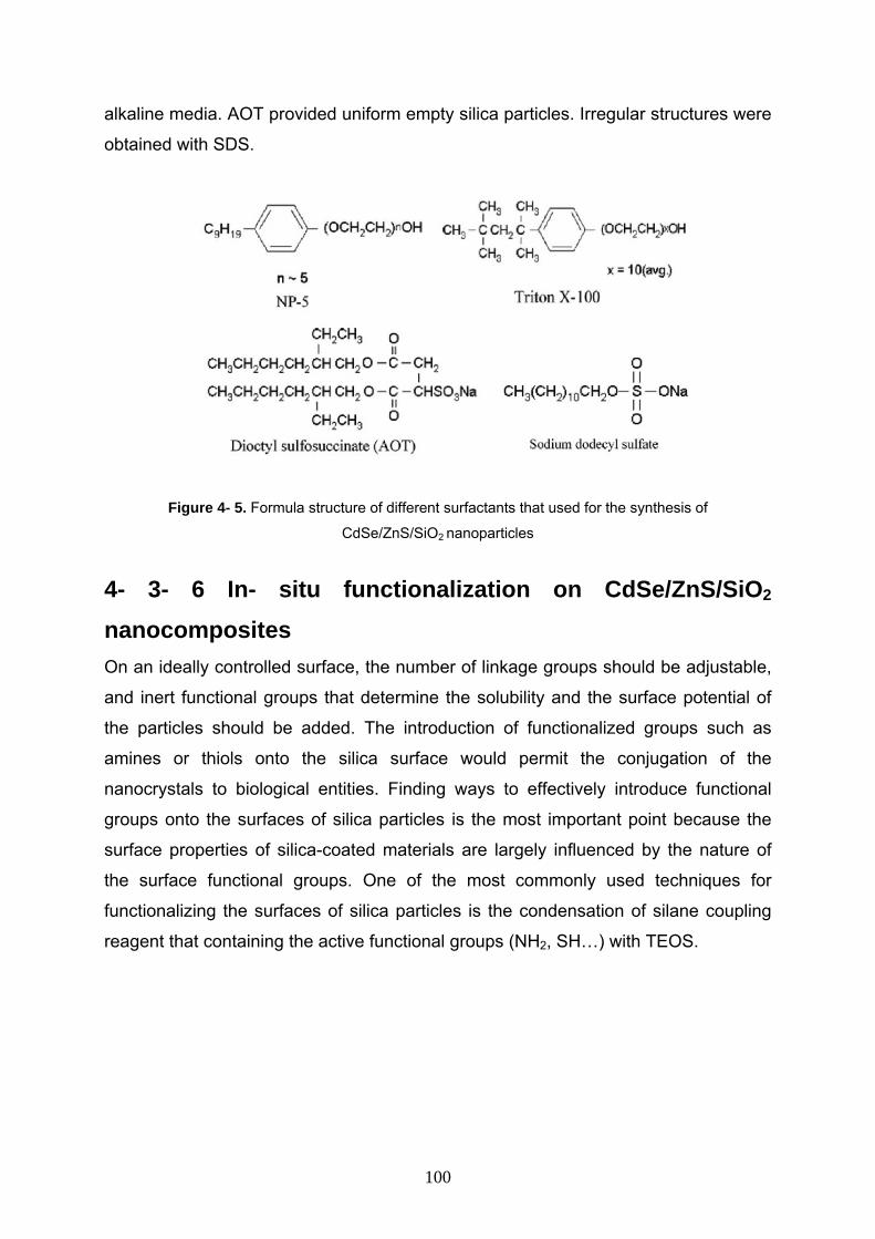
alkaline media. AOT provided uniform empty silica particles. Irregular structures were
obtained with SDS.
Figure 4- 5. Formula structure of different surfactants that used for the synthesis of
CdSe/ZnS/SiO2 nanoparticles
4- 3- 6 In- situ functionalization on CdSe/ZnS/SiO2 nanocomposites
On an ideally controlled surface, the number of linkage groups should be adjustable,
and inert functional groups that determine the solubility and the surface potential of
the particles should be added. The introduction of functionalized groups such as
amines or thiols onto the silica surface would permit the conjugation of the
nanocrystals to biological entities. Finding ways to effectively introduce functional
groups onto the surfaces of silica particles is the most important point because the
surface properties of silica-coated materials are largely influenced by the nature of
the surface functional groups. One of the most commonly used techniques for
functionalizing the surfaces of silica particles is the condensation of silane coupling
reagent that containing the active functional groups (NH2, SH…) with TEOS.
100
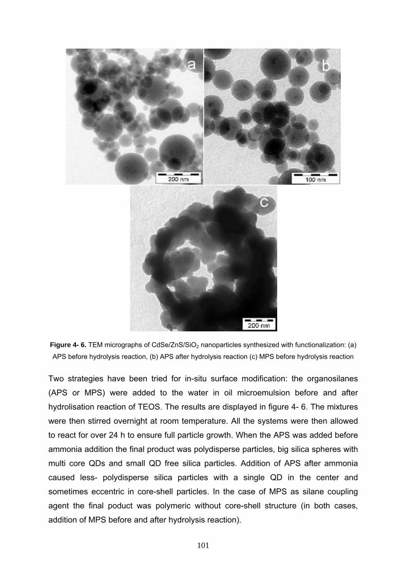
Figure 4- 6. TEM micrographs of CdSe/ZnS/SiO2 nanoparticles synthesized with functionalization: (a)
APS before hydrolysis reaction, (b) APS after hydrolysis reaction (c) MPS before hydrolysis reaction
Two strategies have been tried for in-situ surface modification: the organosilanes
(APS or MPS) were added to the water in oil microemulsion before and after
hydrolisation reaction of TEOS. The results are displayed in figure 4- 6. The mixtures
were then stirred overnight at room temperature. All the systems were then allowed
to react for over 24 h to ensure full particle growth. When the APS was added before
ammonia addition the final product was polydisperse particles, big silica spheres with
multi core QDs and small QD free silica particles. Addition of APS after ammonia
caused less- polydisperse silica particles with a single QD in the center and
sometimes eccentric in core-shell particles. In the case of MPS as silane coupling
agent the final poduct was polymeric without core-shell structure (in both cases,
addition of MPS before and after hydrolysis reaction).
101
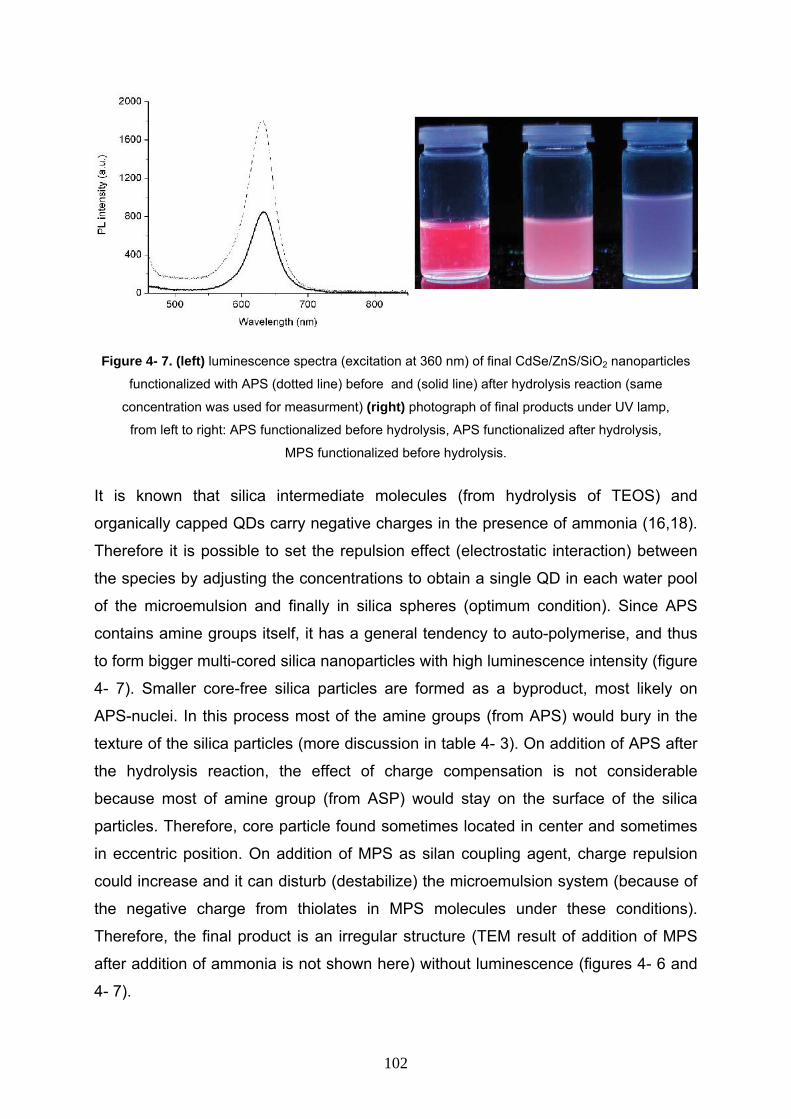
Figure 4- 7. (left) luminescence spectra (excitation at 360 nm) of final CdSe/ZnS/SiO2 nanoparticles
functionalized with APS (dotted line) before and (solid line) after hydrolysis reaction (same
concentration was used for measurment) (right) photograph of final products under UV lamp,
from left to right: APS functionalized before hydrolysis, APS functionalized after hydrolysis,
MPS functionalized before hydrolysis.
It is known that silica intermediate molecules (from hydrolysis of TEOS) and
organically capped QDs carry negative charges in the presence of ammonia (16,18). Therefore it is possible to set the repulsion effect (electrostatic interaction) between
the species by adjusting the concentrations to obtain a single QD in each water pool
of the microemulsion and finally in silica spheres (optimum condition). Since APS
contains amine groups itself, it has a general tendency to auto-polymerise, and thus
to form bigger multi-cored silica nanoparticles with high luminescence intensity (figure
4- 7). Smaller core-free silica particles are formed as a byproduct, most likely on
APS-nuclei. In this process most of the amine groups (from APS) would bury in the
texture of the silica particles (more discussion in table 4- 3). On addition of APS after
the hydrolysis reaction, the effect of charge compensation is not considerable
because most of amine group (from ASP) would stay on the surface of the silica
particles. Therefore, core particle found sometimes located in center and sometimes
in eccentric position. On addition of MPS as silan coupling agent, charge repulsion
could increase and it can disturb (destabilize) the microemulsion system (because of
the negative charge from thiolates in MPS molecules under these conditions).
Therefore, the final product is an irregular structure (TEM result of addition of MPS
after addition of ammonia is not shown here) without luminescence (figures 4- 6 and
4- 7).
102
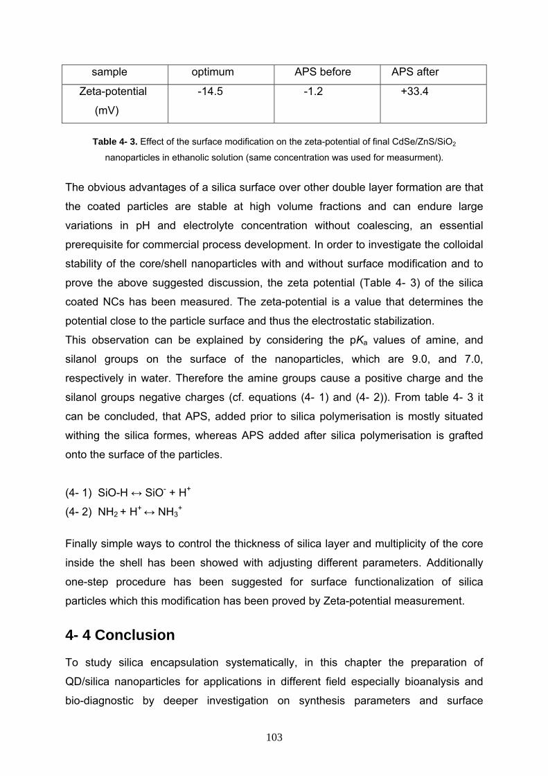
sample optimum APS before APS after
Zeta-potential
(mV)
-14.5 -1.2 +33.4
Table 4- 3. Effect of the surface modification on the zeta-potential of final CdSe/ZnS/SiO2
nanoparticles in ethanolic solution (same concentration was used for measurment).
The obvious advantages of a silica surface over other double layer formation are that
the coated particles are stable at high volume fractions and can endure large
variations in pH and electrolyte concentration without coalescing, an essential
prerequisite for commercial process development. In order to investigate the colloidal
stability of the core/shell nanoparticles with and without surface modification and to
prove the above suggested discussion, the zeta potential (Table 4- 3) of the silica
coated NCs has been measured. The zeta-potential is a value that determines the
potential close to the particle surface and thus the electrostatic stabilization.
This observation can be explained by considering the pKa values of amine, and
silanol groups on the surface of the nanoparticles, which are 9.0, and 7.0,
respectively in water. Therefore the amine groups cause a positive charge and the
silanol groups negative charges (cf. equations (4- 1) and (4- 2)). From table 4- 3 it
can be concluded, that APS, added prior to silica polymerisation is mostly situated
withing the silica formes, whereas APS added after silica polymerisation is grafted
onto the surface of the particles.
(4- 1) SiO-H ↔ SiO- + H+
(4- 2) NH2 + H+ ↔ NH3+
Finally simple ways to control the thickness of silica layer and multiplicity of the core
inside the shell has been showed with adjusting different parameters. Additionally
one-step procedure has been suggested for surface functionalization of silica
particles which this modification has been proved by Zeta-potential measurement.
4- 4 Conclusion To study silica encapsulation systematically, in this chapter the preparation of
QD/silica nanoparticles for applications in different field especially bioanalysis and
bio-diagnostic by deeper investigation on synthesis parameters and surface
103
functionalization has been optimised. Silica coated particles have been synthesized
and several factors investigated which the following conclusions can be drawn from
that: 1- Core/shell structures are not achieved by using every kind of acid or base
(prominent effect on morphology from the nature of catalyst). 2- Added ionic
electrolyte to the microemulsion system can affect the system by ionic strength and
adsorption phenomena in different ways (depends on the concentration of the
electrolyte). 3- An increasing amount of water in microemulsion systems causes
considerable increase in polydispersity and size of core/shell particles. 4- It is
possible to obtain silica coated nanoparticles only by using non-ionic surfactants
(because of the instability of the microemulsion system in the presence of ionic
surfactant, inverse micelles). 5- A systematic study of the design and the
development of the surface-modification schemes for silica coated nanoparticles are
presented. Depending on the structure of silane coupling agents and the time of
addition (before or after hydrolysis reaction) the product can show high luminescence
intensity or considerable colloidal stability. This optimization study provides a solid foundation for the development and effective
utilization of silica coated CdSe/ZnS nanoparticles that can be used in unique
bioanalysis and biotechnological applications.
104
References 1- Y. A. Yang, O. Chen, A. Angerhofer, Y. C. Cao, J. Am. Chem. Soc. 2006, 128,
12428.
2- S. Tavenner-Kruger, Y.S. Park, M. Lonergan, U. Woggon, H.L. Wang, Nano Lett.
2006, 6, 2154.
3- D.S. Jacob, I. Genish, L. Klein, A.Gedanken, J. Phys. Chem. B 2006, 110, 17711.
4- O. Iglesias, X. Batlle, A. Labarta, Phys. Rev. B 2005, 72, 212401.
5- C. Graf, D.L.J. Vossen, A. Imhof, A. Van Blaaderen, Langmuir 2003, 19, 6693.
6- S. Mornet, C. Elissalde, V. Hornebecq, O. Bidault, E. Duguet, A. Brisson, M.
Maglione, Chem. Mater. 2005, 17, 4530.
7- Y. Kobayashi, H. Katakami, E. Mine, D. Nagao, M. Konno, L. M. Liz-Marzàn, J.
Colloid Interface Sci. 2005, 283, 392.
8- L.M. Rossi, L. Shi, F.H. Quina, Z. Rosenzweig, Langmuir 2005, 21, 4277.
9- A. Schroedter, H. Weller, R. Eritja, W. E. Ford, J. M. Wessels, Nano Lett. 2002, 2,
1363.
10- M.J.A.D. Dood, B. Berkhout, C.M.V. Kats, A. Polman, A.V. Blaaderen, Chem.
Mater. 2002, 14, 2849.
11- M. Qhobosheane, S. Santra, P. Zhang, W. Tan, Analyst 2001, 126, 1274.
12- K.S. Rao, K. El-Hami, T. Kodaki, K. Matsushige, K. Makino, J. Colloid Interface
Sci 2005, 289, 125.
13- G.H. Bogush, C.F. Zukoski, J. Colloid Interface Sci 1991, 142, 1.
14- T. Mokari, H. Sertchook, A. Aharoni, Y. Ebenstein, D. Avnir, U. Banin, Chem.
Mater. 2005, 17, 258.
15- F. Teng, Z. Tian, G. Xiong, Z. Xu, Catal. Today 2004, 93, 651.
16- Y. Yang, M. Y. Gao, Adv. Mater. 2005, 17, 2354.
17- S.T. Selvan, T.T. Tan, J.Y. Ying, Adv. Mater. 2005, 17, 1620.
18- S.-L. Chen, P. Dong, G.-H. Yang, J.-J. Yang, Ind. Eng. Chem. Res. 1996, 35,
4487.
105
Chapter five
Hollow silica nanospheres: synthesis
and application
106
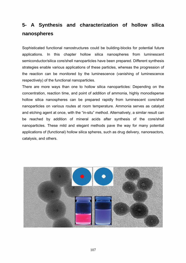
5- A Synthesis and characterization of hollow silica nanospheres
Sophisticated functional nanostructures could be building-blocks for potential future
applications. In this chapter hollow silica nanospheres from luminescent
semiconductor/silica core/shell nanoparticles have been prepared. Different synthesis
strategies enable various applications of these particles, whereas the progression of
the reaction can be monitored by the luminescence (vanishing of luminescence
respectively) of the functional nanoparticles.
There are more ways than one to hollow silica nanoparticles: Depending on the
concentration, reaction time, and point of addition of ammonia, highly monodisperse
hollow silica nanospheres can be prepared rapidly from luminescent core/shell
nanoparticles on various routes at room temperature. Ammonia serves as catalyst
and etching agent at once, with the “in-situ” method. Alternatively, a similar result can
be reached by addition of mineral acids after synthesis of the core/shell
nanoparticles. These mild and elegant methods pave the way for many potential
applications of (functional) hollow silica spheres, such as drug delivery, nanoreactors,
catalysis, and others.
107
5- A- 1 Introduction Inorganic hollow nanospheres with well-defined architectures are of interest due to
their low density, low toxicity, large surface area, high chemical and thermal stability,
and surface permeability. Such hollow capsules can pave the way for applications in
catalysis, as stationary phase for selective separation, controlled (drug) delivery,
artificial cells, light fillers, low dielectric constant or prosthetic materials or photonic
crystals (1-4). Recently, a growing interest has also been directed towards the
exploration of porous silica as gas and heavy metal ion adsorbents, as well as
inorganic carriers for enzyme immobilization. Characteristically, the as-prepared
monodiserse hollow silica particles are soluble in organic solvents including acetone,
chloroform, tetrahydrofuran, etc. This feature of the particles can be used in
application fields including delivery systems, nanoreactors, coating technology,
catalysis, and so forth (5-11).
Extensive research has been undertaken into the synthesis of inorganic hollow
microspheres over the past decade. There are a variety of pathways to synthesise
hollow particles of various compositions. Hollow inorganic particles were mostly
made by removing a core material from core/shell nanoparticles. In a typical
procedure, template particles are coated in solution either by controlled surface
precipitation of inorganic molecule precursors (silica, titania, etc.) or by direct surface
reactions that utilize specific functional groups on the cores to create core/shell
composites. The template particles are subsequently removed by selective
dissolution in an appropriate solvent or by calcination at elevated temperatures in air
to generate hollow spheres. For example, sulfonated polystyrene core-shell gel
particles have been used as templates to prepare hollow titania spheres. Silica
particles used as template to fabricate polymer hollow spheres by dispersion
polymerization around monodispersed silica particles, and then removed the silica
cores by HF etching (12-16). Additionally, hollow silica spheres have been made by
templating routes, which make use of vesicles, emulsion systems, acoustic
cavitations or electrically forced liquid jets (17-23).
Unfortunately, although the above pioneering works are very interesting, the
preparation processes seem to be time consuming. Firstly, multistep processes are
needed for the synthesis of core/shell composite particles, e.g., the surface
108
functionalization of templating particles/exchange of solvent/coating reaction for the
templating particles approach, or the repeated adsorption/centrifugation/water
wash/redispersion cycles. Secondly, in order to obtain hollow spheres from the
core/shell composite particles, removing the core particles by selective dissolution in
an appropriate solvent or by calcination at elevated temperature in air is
indispensable. Therefore, the development of facile and feasible methods to prepare
hollow spheres remains a great challenge to materials scientists.
To overcome this problem, I describe for the first time a novel, room-temperature and
mild synthesis process for hollow silica nanoparticles using luminescent CdSe/ZnS
nanoparticles as templates. Silica encapsulation and dissolution of the core particles
can be done simultaneously (in-situ) by modification of the reaction conditions. The
size and shape of the hollow spheres can be controlled by the dimensions of the core
nanoparticles. The reaction can be monitored by detection of the luminescence of the
cores.
5- A- 2 Experimental Section 5- A- 2- 1 Chemicals All of the chemicals were used as received from Aldrich without further purification.
Polyethylene glycol nonylphenyl ether (Synperonic NP 5) was purchased from Fluka,
ammonia aqueous solution (33 wt %), dimethylamine (40 wt %) cyclohexane,
acetone, butanol, propanol, and ethanol from internal sources.
5- A- 2- 2 Preparation of CdSe/ZnS/SiO2 nanocomposite The CdSe/ZnS/SiO2 particles were prepared by means of a modified water in oil
microemulsion method at room temperature (chapter 2). Typically, 10 ml
cyclohexane, 1.3 ml NP-5 as surfactant, 400 µl solution of as-prepared luminescent
CdSe/ZnS NCs (8.72 × 10⁻⁷ mol/L ) in Chloroform and 80 µl of TEOS (tetraethyl
orthosilicate) as a precursor for silica formation were added in a flask under vigorous
stirring. 30 min after the microemulsion system was formed, 150 µl ammonia
aqueous solution (33wt %) was introduced to initiate the encapsulation process.
Subsequently, the reaction mixture was aged for 24 h at room temperature. After the
109
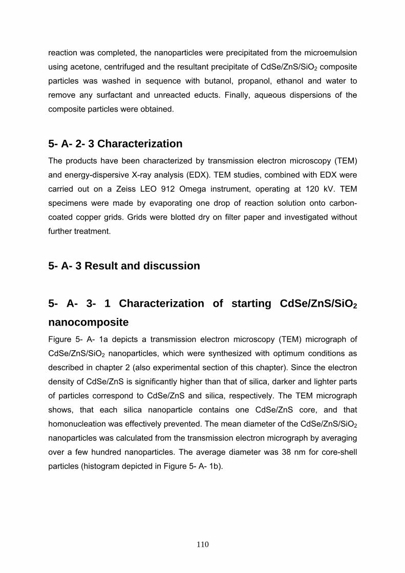
reaction was completed, the nanoparticles were precipitated from the microemulsion
using acetone, centrifuged and the resultant precipitate of CdSe/ZnS/SiO2 composite
particles was washed in sequence with butanol, propanol, ethanol and water to
remove any surfactant and unreacted educts. Finally, aqueous dispersions of the
composite particles were obtained.
5- A- 2- 3 Characterization The products have been characterized by transmission electron microscopy (TEM)
and energy-dispersive X-ray analysis (EDX). TEM studies, combined with EDX were
carried out on a Zeiss LEO 912 Omega instrument, operating at 120 kV. TEM
specimens were made by evaporating one drop of reaction solution onto carbon-
coated copper grids. Grids were blotted dry on filter paper and investigated without
further treatment.
5- A- 3 Result and discussion 5- A- 3- 1 Characterization of starting CdSe/ZnS/SiO2 nanocomposite Figure 5- A- 1a depicts a transmission electron microscopy (TEM) micrograph of
CdSe/ZnS/SiO2 nanoparticles, which were synthesized with optimum conditions as
described in chapter 2 (also experimental section of this chapter). Since the electron
density of CdSe/ZnS is significantly higher than that of silica, darker and lighter parts
of particles correspond to CdSe/ZnS and silica, respectively. The TEM micrograph
shows, that each silica nanoparticle contains one CdSe/ZnS core, and that
homonucleation was effectively prevented. The mean diameter of the CdSe/ZnS/SiO2
nanoparticles was calculated from the transmission electron micrograph by averaging
over a few hundred nanoparticles. The average diameter was 38 nm for core-shell
particles (histogram depicted in Figure 5- A- 1b).
110
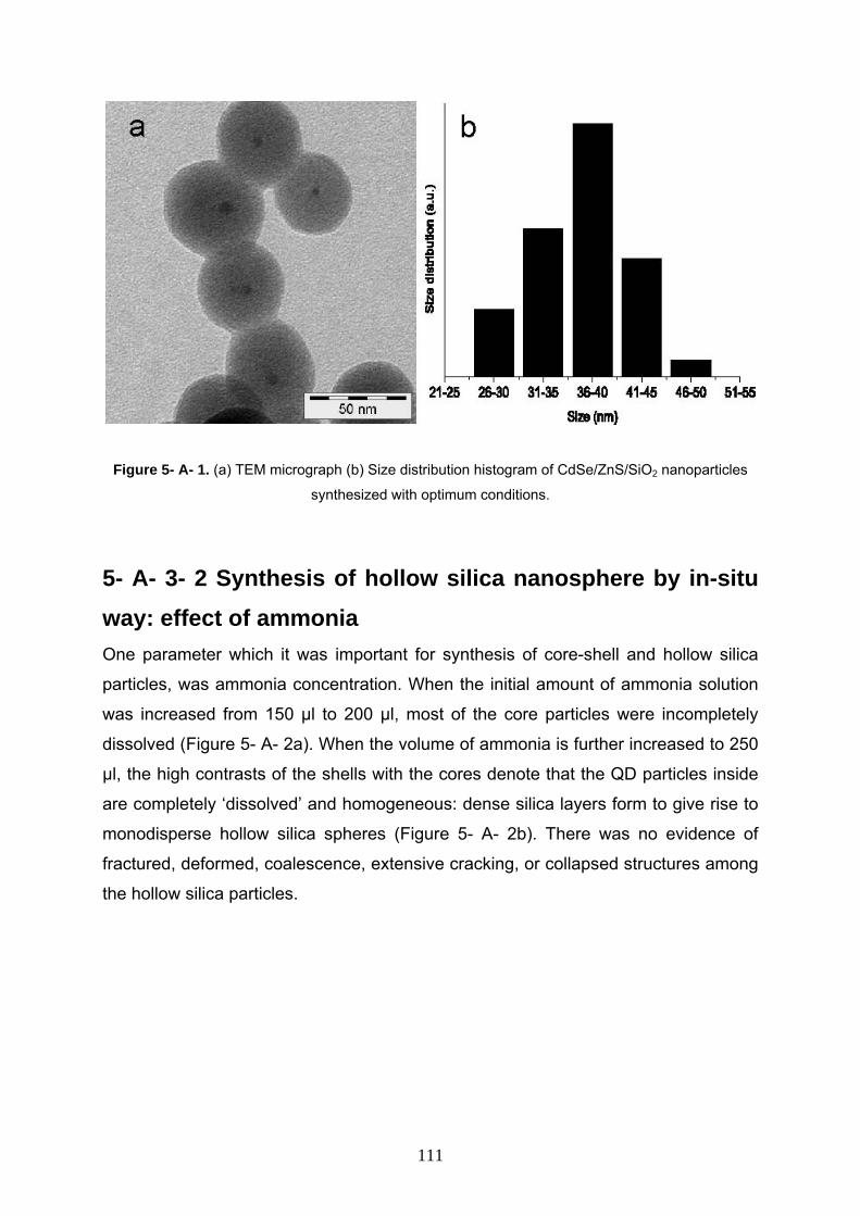
Figure 5- A- 1. (a) TEM micrograph (b) Size distribution histogram of CdSe/ZnS/SiO2 nanoparticles
synthesized with optimum conditions.
5- A- 3- 2 Synthesis of hollow silica nanosphere by in-situ way: effect of ammonia One parameter which it was important for synthesis of core-shell and hollow silica
particles, was ammonia concentration. When the initial amount of ammonia solution
was increased from 150 µl to 200 µl, most of the core particles were incompletely
dissolved (Figure 5- A- 2a). When the volume of ammonia is further increased to 250
µl, the high contrasts of the shells with the cores denote that the QD particles inside
are completely ‘dissolved’ and homogeneous: dense silica layers form to give rise to
monodisperse hollow silica spheres (Figure 5- A- 2b). There was no evidence of
fractured, deformed, coalescence, extensive cracking, or collapsed structures among
the hollow silica particles.
111
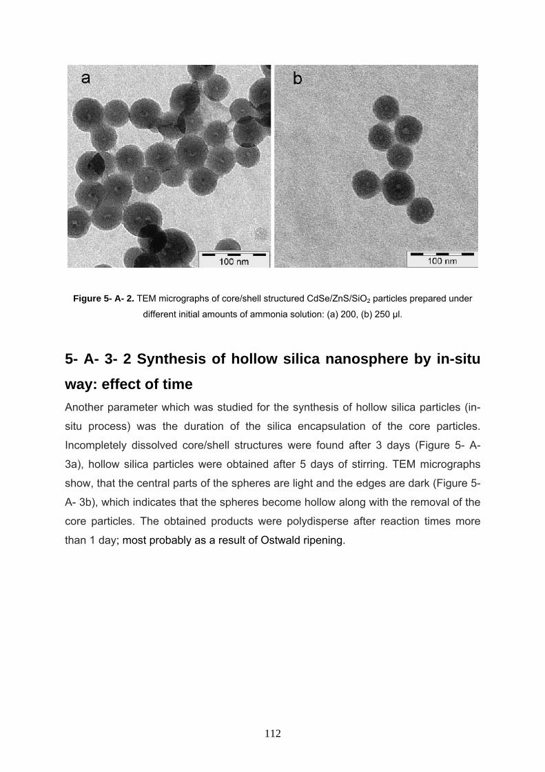
Figure 5- A- 2. TEM micrographs of core/shell structured CdSe/ZnS/SiO2 particles prepared under
different initial amounts of ammonia solution: (a) 200, (b) 250 µl. 5- A- 3- 2 Synthesis of hollow silica nanosphere by in-situ way: effect of time Another parameter which was studied for the synthesis of hollow silica particles (in-
situ process) was the duration of the silica encapsulation of the core particles.
Incompletely dissolved core/shell structures were found after 3 days (Figure 5- A-
3a), hollow silica particles were obtained after 5 days of stirring. TEM micrographs
show, that the central parts of the spheres are light and the edges are dark (Figure 5-
A- 3b), which indicates that the spheres become hollow along with the removal of the
core particles. The obtained products were polydisperse after reaction times more
than 1 day; most probably as a result of Ostwald ripening.
112
Figure 5- A- 3. TEM micrographs of core/shell structured CdSe/ZnS/SiO2 particles obtained after
different reaction times: (a) 3 and (b) 5 days.
The EDX analysis of the CdSe/ZnS/SiO2 nanoparticls as well as hollow silica
nanoparticles confirms the presence of Cd, Se, Zn, S, Si and O in the core/shell
nanoparticles and moreover, Si and O in hollow silica spheres (figure 5- A- 4) (Cu
and C are introduced from the TEM grid in the TEM apparatus). Thus, the complete
dissolution of the cores was proven.
113
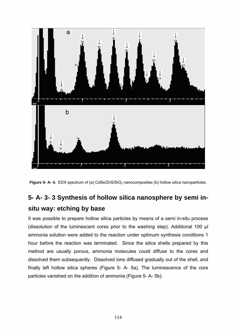
Figure 5- A- 4. EDX spectrum of (a) CdSe/ZnS/SiO2 nanocomposites (b) hollow silica nanoparticles.
5- A- 3- 3 Synthesis of hollow silica nanosphere by semi in-situ way: etching by base It was possible to prepare hollow silica particles by means of a semi in-situ process
(dissolution of the luminescent cores prior to the washing step). Additional 100 µl
ammonia solution were added to the reaction under optimum synthesis conditions 1
hour before the reaction was terminated. Since the silica shells prepared by this
method are usually porous, ammonia molecules could diffuse to the cores and
dissolved them subsequently. Dissolved ions diffused gradually out of the shell, and
finally left hollow silica spheres (Figure 5- A- 5a). The luminescence of the core
particles vanished on the addition of ammonia (Figure 5- A- 5b).
114
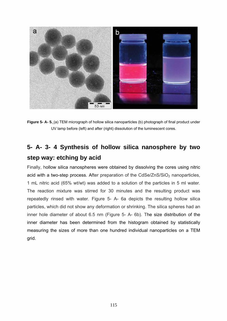
Figure 5- A- 5. (a) TEM micrograph of hollow silica nanoparticles (b) photograph of final product under
UV lamp before (left) and after (right) dissolution of the luminescent cores.
5- A- 3- 4 Synthesis of hollow silica nanosphere by two step way: etching by acid Finally, hollow silica nanospheres were obtained by dissolving the cores using nitric
acid with a two-step process. After preparation of the CdSe/ZnS/SiO2 nanoparticles,
1 mL nitric acid (65% wt/wt) was added to a solution of the particles in 5 ml water.
The reaction mixture was stirred for 30 minutes and the resulting product was
repeatedly rinsed with water. Figure 5- A- 6a depicts the resulting hollow silica
particles, which did not show any deformation or shrinking. The silica spheres had an
inner hole diameter of about 6.5 nm (Figure 5- A- 6b). The size distribution of the
inner diameter has been determined from the histogram obtained by statistically
measuring the sizes of more than one hundred individual nanoparticles on a TEM
grid.
115
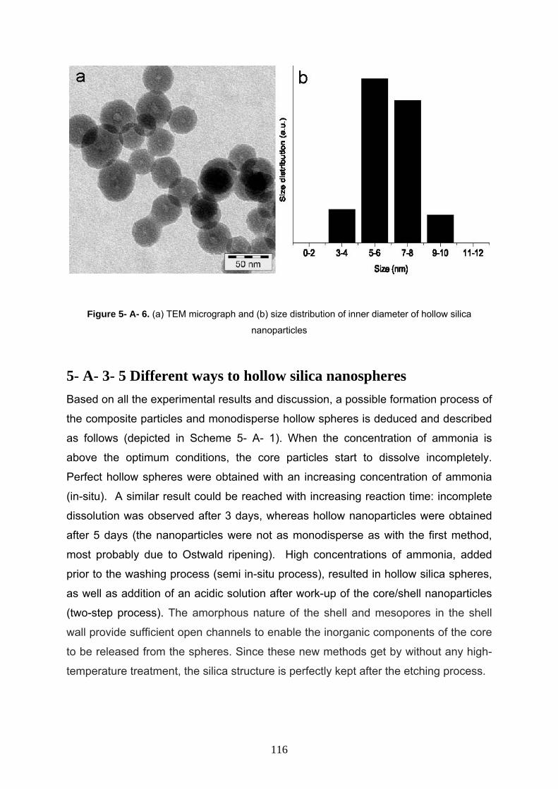
Figure 5- A- 6. (a) TEM micrograph and (b) size distribution of inner diameter of hollow silica
nanoparticles
5- A- 3- 5 Different ways to hollow silica nanospheres Based on all the experimental results and discussion, a possible formation process of
the composite particles and monodisperse hollow spheres is deduced and described
as follows (depicted in Scheme 5- A- 1). When the concentration of ammonia is
above the optimum conditions, the core particles start to dissolve incompletely.
Perfect hollow spheres were obtained with an increasing concentration of ammonia
(in-situ). A similar result could be reached with increasing reaction time: incomplete
dissolution was observed after 3 days, whereas hollow nanoparticles were obtained
after 5 days (the nanoparticles were not as monodisperse as with the first method,
most probably due to Ostwald ripening). High concentrations of ammonia, added
prior to the washing process (semi in-situ process), resulted in hollow silica spheres,
as well as addition of an acidic solution after work-up of the core/shell nanoparticles
(two-step process). The amorphous nature of the shell and mesopores in the shell
wall provide sufficient open channels to enable the inorganic components of the core
to be released from the spheres. Since these new methods get by without any high-
temperature treatment, the silica structure is perfectly kept after the etching process.
116
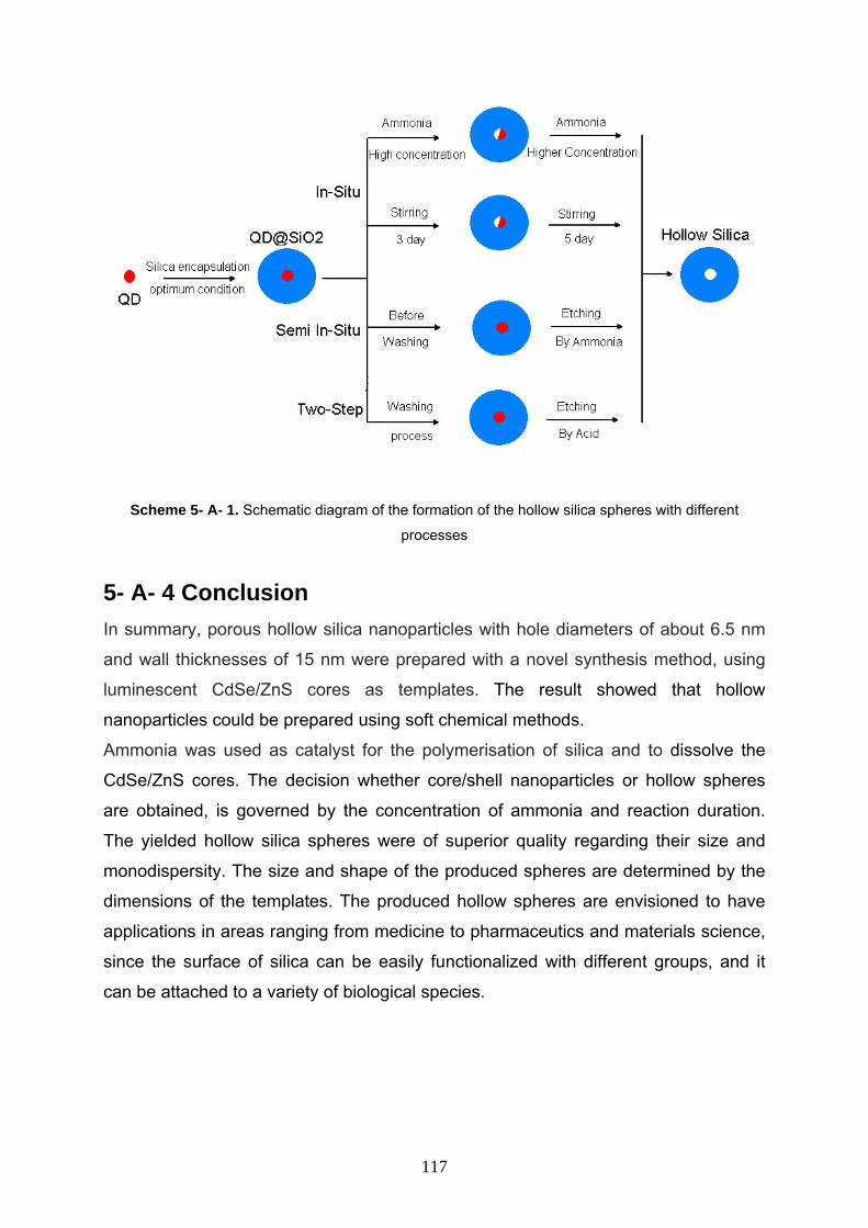
Scheme 5- A- 1. Schematic diagram of the formation of the hollow silica spheres with different
processes 5- A- 4 Conclusion In summary, porous hollow silica nanoparticles with hole diameters of about 6.5 nm
and wall thicknesses of 15 nm were prepared with a novel synthesis method, using
luminescent CdSe/ZnS cores as templates. The result showed that hollow
nanoparticles could be prepared using soft chemical methods.
Ammonia was used as catalyst for the polymerisation of silica and to dissolve the
CdSe/ZnS cores. The decision whether core/shell nanoparticles or hollow spheres
are obtained, is governed by the concentration of ammonia and reaction duration.
The yielded hollow silica spheres were of superior quality regarding their size and
monodispersity. The size and shape of the produced spheres are determined by the
dimensions of the templates. The produced hollow spheres are envisioned to have
applications in areas ranging from medicine to pharmaceutics and materials science,
since the surface of silica can be easily functionalized with different groups, and it
can be attached to a variety of biological species.
117
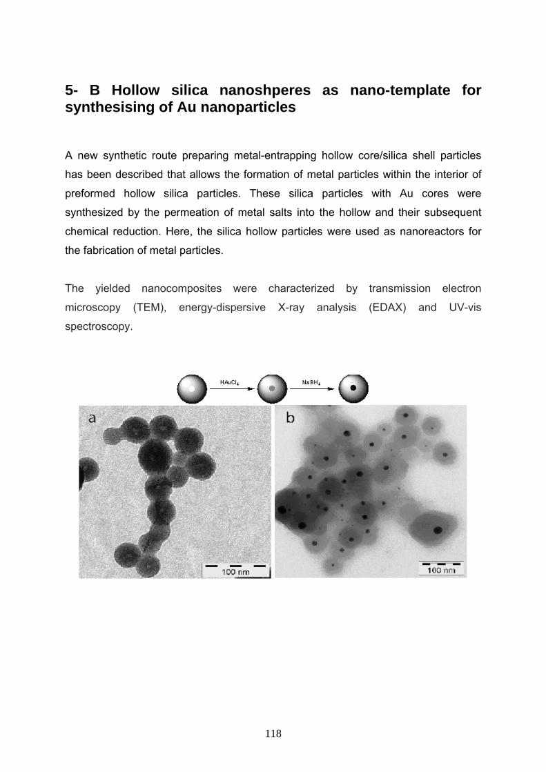
5- B Hollow silica nanoshperes as nano-template for synthesising of Au nanoparticles A new synthetic route preparing metal-entrapping hollow core/silica shell particles
has been described that allows the formation of metal particles within the interior of
preformed hollow silica particles. These silica particles with Au cores were
synthesized by the permeation of metal salts into the hollow and their subsequent
chemical reduction. Here, the silica hollow particles were used as nanoreactors for
the fabrication of metal particles.
The yielded nanocomposites were characterized by transmission electron
microscopy (TEM), energy-dispersive X-ray analysis (EDAX) and UV-vis
spectroscopy.
118
5- B- 1 Introduction Metal nanoparticles and gold in particular has been the subject of extensive research
due to their unique applications in many areas such as nonlinear optical switching,
immunoassay labeling, and Raman spectroscopy enhancement. Gold and silver
colloids are probably the most studied and best established systems, and a variety of
procedures have been developed to process them as stable dispersions
characterized by relatively small size variations (24-26). The properties of these
colloids can be further tailored by coating their surfaces with uniform, conformal
shells made of dielectric materials such as silica. In principle, one can achieve a
precise control over the optical properties of these core-shell colloids by fine-tuning
the chemical composition, structure, and dimensions of the cores or shells (27-30).
The synthesis of such materials by wet chemical methods is based on the reduction
of an inorganic or organo-metallic precursor in the presence of a stabilizing agent
(31, 32). The surface of nanoscaled materials is very reactive, and needs to be
protected by surface ligands to avoid irreversible growth and agglomeration. The
choice of such ligands is critical for the monodispersity and the quality of the resulting
particles. Different compounds such as surfactants or polymers were used for this
purpose. The confinement within nano-reactors such as micelles and dendrimers was
utilised to stabilise metal nanoparticles as well. A further method is the template
synthesis, within porous host materials such as alumina and mesoporous silica to
confine nanoparticles and nanowires as guests (33-38). An alternative and advantageous route to stabilize and functionalize nanoparticles
colloidally is to encapsulate them with silica shells while silica is an inert, robust and
optically transparent material. The silica shells not only enhance the colloidal stability,
but also control the distance between core particles within assemblies by thickness of
the shell. Furthermore, this shell is hydrophilic, biocompatible and easy to
functionalize with several groups using different silane coupling agents. These
unique characteristics and the possibility for bio-conjugation made the silica coating
an attractive way for bio-analytical and medical applications of metal nanoparticles. In this part of chapter 5, the preparation of Au core silica shell particles by pre-
shell/post-core method, a new synthetic route that involves the formation of metal
cores within preformed shells has been described. However, to the best of my
knowledge, they have not been used as reactors for nanoparticle synthesis so far.
119
5- B- 2 Experimental section 5- B- 2- 1 Chemicals Polyethylene glycol nonylphenyl ether (Synperonic NP 5), HNO3 (>69.5%) was
purchased from Fluka and NaBH4 from Merck. All of the other chemicals were used
as received from Aldrich without further purification. Ammonia aqueous solution (33
wt %), dimethylamine (40 wt %), cyclohexane, acetone, butanol, propanol, and
ethanol from internal sources.
5- B- 2- 2 Synthesis of hollow silica nanospheres Hollow silica particles were formed starting from SiO2 encapsulated quantum dots
(which is mentioned in this chapter, part A) and then, they were used as reactors to
prepare the gold encapsulated composites. In a typical synthesis, to 5 mL of as
prepared CdSe/ZnS/SiO2, 1 mL of HNO3 (>69.5%) was added. The mixture was
sonicated in an ultra-sonic bath for 30 minutes and then the white product, no more
photoluminescent, was precipitated and washed respectively with butanol, propanol,
ethanol and water.
5- B- 2- 3 Synthesis of Au/silica nanoparticles Last precipitate from above mentioned process was redispersed in 400 µL of water
and reacted with an excess of HAuCl4 (2 mL of 1% solution). After 30 minutes of
sonication and 2 days of reaction, an excess of reducing agent was added (1 mL of
2M NaBH4). The red-purple precipitate was washed with water until the supernatant
passed from yellow (excess of gold precursor) to colorless.
5- B- 2- 4 Characterization methods
To determine the size and shape of as-prepared and silica encapsulated NC’s, the
Transmission Electron Microscope (TEM), Model Zeiss LEO 912 Omega has been
used, which operated at 120 kV. The samples for the TEM and EDX study were
prepared by drop casting of colloidal solutions of NCs onto carbon films, supported
by a Cu grid. The room-temperature absorption measurements were performed using
colloidal solutions of NCs with the UV-visible J&M TIDAS diode array spectrometer.
120
5- B- 3 Result and discussion Spherical colloids with hollow interiors have received considerable attention due to
their niche application as small containers for microencapsulation. Templating
against various types of colloidal particles has been intensively explored as an
effective route to the generation of hollow spheres from materials as diverse as
inorganic ceramics, organic polymers, and their hybrids. Most work in this area has,
however, been focused on the development of synthetic methodologies. Very little
attention has been directed toward the functionalization of the interiors of these
hollow particles. In the present part of chapter 5, the metal particles were grown in situ, in the internal
cavity of the previously prepared hollow silica particles. The latter were synthesized
from silica coated CdSe/ ZnS nanocomposites as mentioned in chapter 2. The
etching of the core material was possible in acidic or alkaline conditions, due to the
porosity of the silica shell. This strategy was exploited to transfer a gold precursor
and a reducing compound into the silica’s empty cavity, giving rise to the Au/SiO2
nanocomposites. The schematic procedure for the preparation of silica particles with
metal cores is shown in Scheme 5- B- 1. The first step involved the permeation of
Au3+ ions into the preformed silica shells then an excess amount of NaBH4 as
reducing agent was added. The latter could diffuse into the cavity of the silica
spheres, which was filled with Au3+ cations. In the next step, Au metal cores were
formed in the interior of silica shells by chemical reduction. The metal nanoparticle
formation took place by nucleation and growth of Au(0) atoms. The silica shell
avoided further growth of the nanoparticles, acting as a template (as confinement
factor), and finally stabilized them. The final product is a gold nanometric particle
surrounded by a silica shell.
121
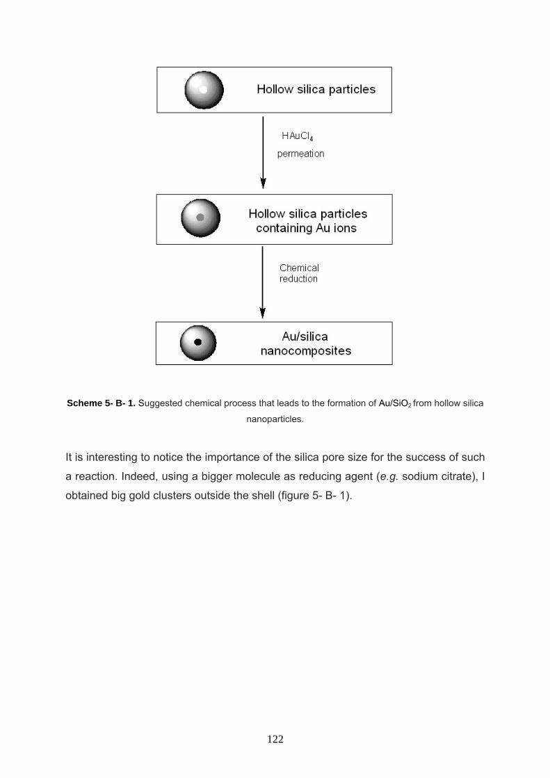
Scheme 5- B- 1. Suggested chemical process that leads to the formation of Au/SiO2 from hollow silica
nanoparticles.
It is interesting to notice the importance of the silica pore size for the success of such
a reaction. Indeed, using a bigger molecule as reducing agent (e.g. sodium citrate), I
obtained big gold clusters outside the shell (figure 5- B- 1).
122
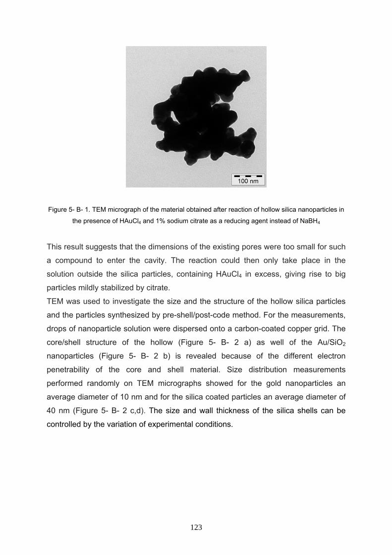
Figure 5- B- 1. TEM micrograph of the material obtained after reaction of hollow silica nanoparticles in
the presence of HAuCl4 and 1% sodium citrate as a reducing agent instead of NaBH4
This result suggests that the dimensions of the existing pores were too small for such
a compound to enter the cavity. The reaction could then only take place in the
solution outside the silica particles, containing HAuCl4 in excess, giving rise to big
particles mildly stabilized by citrate.
TEM was used to investigate the size and the structure of the hollow silica particles
and the particles synthesized by pre-shell/post-code method. For the measurements,
drops of nanoparticle solution were dispersed onto a carbon-coated copper grid. The
core/shell structure of the hollow (Figure 5- B- 2 a) as well of the Au/SiO2
nanoparticles (Figure 5- B- 2 b) is revealed because of the different electron
penetrability of the core and shell material. Size distribution measurements
performed randomly on TEM micrographs showed for the gold nanoparticles an
average diameter of 10 nm and for the silica coated particles an average diameter of
40 nm (Figure 5- B- 2 c,d). The size and wall thickness of the silica shells can be
controlled by the variation of experimental conditions.
123
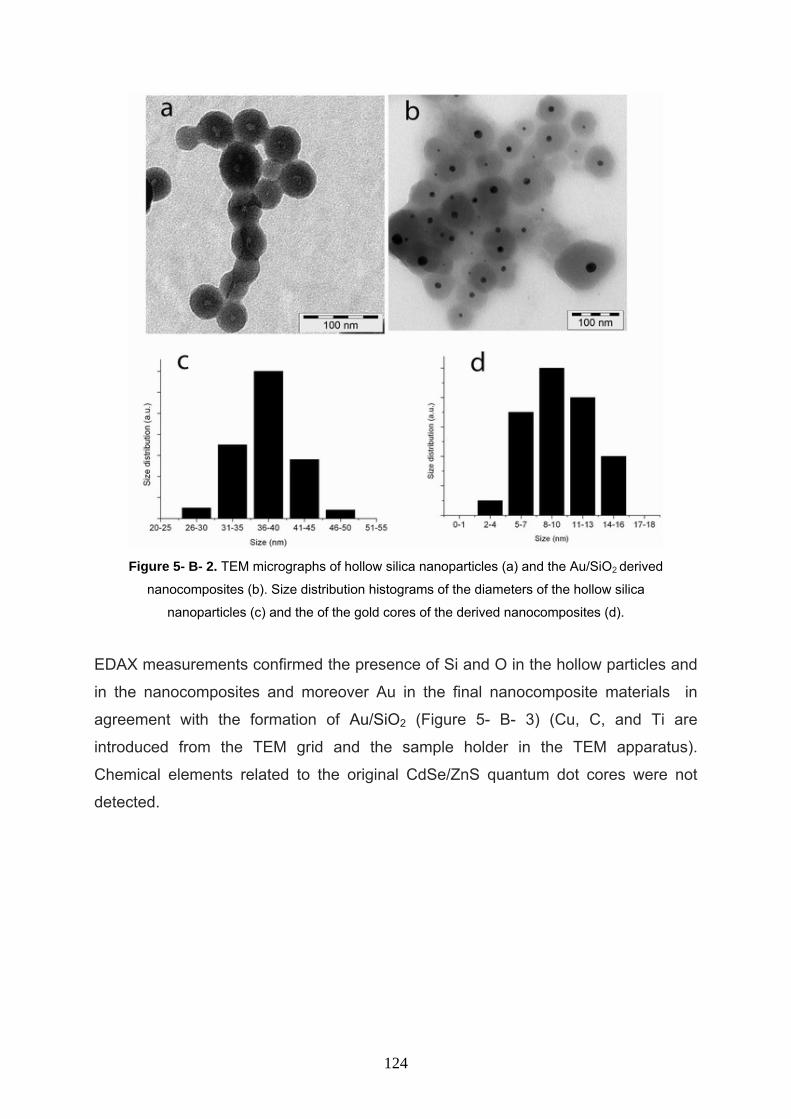
Figure 5- B- 2. TEM micrographs of hollow silica nanoparticles (a) and the Au/SiO2 derived
nanocomposites (b). Size distribution histograms of the diameters of the hollow silica
nanoparticles (c) and the of the gold cores of the derived nanocomposites (d).
EDAX measurements confirmed the presence of Si and O in the hollow particles and
in the nanocomposites and moreover Au in the final nanocomposite materials in
agreement with the formation of Au/SiO2 (Figure 5- B- 3) (Cu, C, and Ti are
introduced from the TEM grid and the sample holder in the TEM apparatus).
Chemical elements related to the original CdSe/ZnS quantum dot cores were not
detected.
124
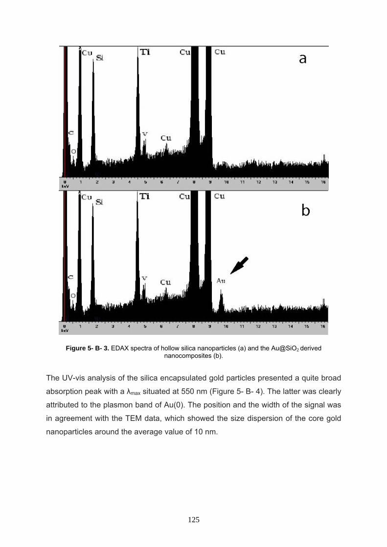
Figure 5- B- 3. EDAX spectra of hollow silica nanoparticles (a) and the Au@SiO2 derived nanocomposites (b).
The UV-vis analysis of the silica encapsulated gold particles presented a quite broad
absorption peak with a λmax situated at 550 nm (Figure 5- B- 4). The latter was clearly
attributed to the plasmon band of Au(0). The position and the width of the signal was
in agreement with the TEM data, which showed the size dispersion of the core gold
nanoparticles around the average value of 10 nm.
125
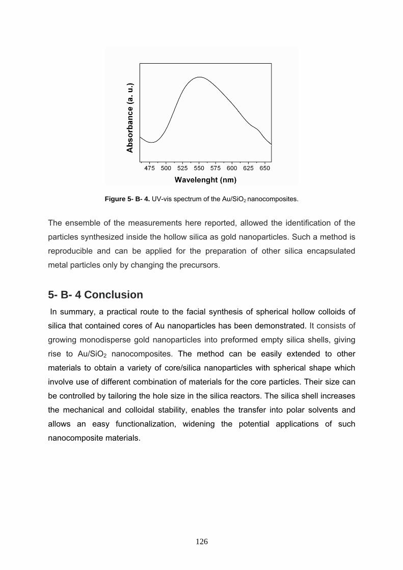
Figure 5- B- 4. UV-vis spectrum of the Au/SiO2 nanocomposites.
The ensemble of the measurements here reported, allowed the identification of the
particles synthesized inside the hollow silica as gold nanoparticles. Such a method is
reproducible and can be applied for the preparation of other silica encapsulated
metal particles only by changing the precursors.
5- B- 4 Conclusion In summary, a practical route to the facial synthesis of spherical hollow colloids of
silica that contained cores of Au nanoparticles has been demonstrated. It consists of
growing monodisperse gold nanoparticles into preformed empty silica shells, giving
rise to Au/SiO2 nanocomposites. The method can be easily extended to other
materials to obtain a variety of core/silica nanoparticles with spherical shape which
involve use of different combination of materials for the core particles. Their size can
be controlled by tailoring the hole size in the silica reactors. The silica shell increases
the mechanical and colloidal stability, enables the transfer into polar solvents and
allows an easy functionalization, widening the potential applications of such
nanocomposite materials.
126
References 1- J. J. E. Lee, J. Lee, J. H. Yu, B. C. Kim, K. An, Y. Hwang, C. H. Shin, J. G. Park, J.
Kim, T. Hyeon, J. Am. Chem. Soc. 2006, 128, 688.
2- M. Lal, L. Levy, K. S. Kim, G. S. He, X. Wang, Y. H. Min, S. Pakatchi, P. N.
Prasad, Chem. Mater. 2000, 12, 2632.
3- K. Sharma, S. Das, A. Maitra, J. Colloid Interface Sci. 2005, 284, 358.
4- T. XY, L. SM, K Li, J. Membrane. Sci. 2001, 188, 87.
5- N. E. Botterhuis, Q. Sun, P. C. M. M. Magusin, R. A. Van Santen, N. A. J. M.
Sommerdijk, Chem. Eur. J. 2006, 12, 1448.
6- Z. Z. Li, S. A. Xu, L. X. Wen, F. Liu, A. Q. Liu, Q. Wang, H. Y. Sun, W. Yu, J. F.
Chen, J. Control. Release. 2006, 111, 81.
7- J. F. Chen, H. M. Ding, J. X. Wang, L. Shao, Biomaterials 2004, 25, 723.
8- A. P. R. Johnston, B. J. Battersby, G. A. Lawrie, M. Trau, Chem. Commun. 2005, 848.
9- Z. Z. Li, L. X. Wen, L. Shao, J. F. Chen, J. Control. Release. 2004, 98, 245.
10- S. B. Yoon, J. Y. Kim, J. H. Kim, S. G. Park, J. Y. Kim, Lee, C. W. Yu, Curr. Appl.
Phys. 2006, 6, 1059.
11- F. Caruso, R. A. Caruso, H. Möhwald, Science 1998, 282, 1111.
12- K. Zhang, L. Zheng, X. Zhang, X. Chen, B. Yang, Colloid. Surface. A, 2006, 277,
145.
13- G. Liu, G. Hong, J. Solid State Chem. 2005, 178, 1647.
14- J. J. L. M. Cornelissen, E. F. Connor, H. C. Kim, V. Y. Lee, T. Magibitang, P. M.
Rice, W. Volksen, L. K. Sundberg, R. D. Miller, Chem. Commun. 2003, 1010.
15- X. Ding, K. Yu, Y. Jiang, H. Bala, H. Zhang, Z. Wang, Mater. Lett. 2004, 58,
3618.
16- X. Ji, Q. Hu, J. E. Hampsey, X. Qiu, L. Gao, J. He, Y. Lu, Chem. Mater. 2006,
18, 2265.
17- C. E. Fowler, D. Khushalani, S. Mann, J. Mater. Chem. 2001, 11, 1968.
18- S. S. Kim, W. Zhang, T. J. Pinnavaia, Science 1998, 282, 1302.
19- D. H. W. Hubert, M. Jung, P. M. Frederik, P. H. H. Bomans, J. Meuldijk, A. L.
German, Adv. Mater. 2000, 12, 1286.
20- J. F. Chen, H. M. Ding, J. X. Wang, L. Shao, Biomaterials. 2004, 25, 723.
21- C. Yu, B. Tian, J. Fan, G. D. Stucky, D. Zhao, Chem. Lett. 2002, 62.
22- Q. Sun, P. J. Kooyman, J. G. Grossmann, P. H. H. Bomans, P. M. Frederik, P. C.
127
M. M. Magusin, T. P. M. Beelen, R. A. van Santen, N. A. J. M. Sommerdijk, Adv.
Mater. 2003, 15, 1097.
23- G. Larsen, R. V. Ortiz, K. Minchow, A. Barrero, I. G. Loscertales, J. Am. Chem.
Soc. 2003, 125, 1154.
24- R. Narayanan, M. A. El-Sayed, J. Phys. Chem. B, 2005, 109, 12663.
25- H.W. Liao, C. L. Nehl and J. H. Hafner, Nanomedicine, 2006, 1, 201.
26- J. R. Lakowicz, J. Malicka, I. Gryczynski, Z. Gryczynski and C. D. Geddes, J.
Phys. D: Appl. Phys., 2003, 36, R240.
27- L. M. Liz-Marzan, P. Mulvaney, J. Phys. Chem. B. 2003, 107, 7312.
28- V. Salgueirino-Maceira, F. Caruso, L. M. Liz-Marzan, J. Phys. Chem. B., 2003,
107, 10990.
29- T. Ung, L. M. Liz-Marzan, P. Mulvaney, Langmuir 1998, 14, 3740.
30- T. Ung, L. M. Liz-Marzan, P. Mulvaney, J. Phys. Chem. B 1999, 103, 6770.
31- M.-C. Daniel and D. Astruc, Chem. Rev., 2004, 104, 293.
32- A. Roucoux, J. Schulz, H. Patin, Chem. Rev., 2002, 102, 3757.
33- A. Taleb, C. Petit and M. P. Pileni, Chem. Mater., 1997, 9, 950.
34- D. Robertson, B. Tiersch, S. Kosmella and J. Koetz, J. Colloid Interface
Sci., 2007, 305, 345.
35- I. Capek, Adv. Colloid Interface Sci., 2004, 110, 49.
36- A. Fukuoka, M. Ichikawa, Top. Catal., 2006, 40, 103.
37- A. Fukuoka,H. Araki, J.-I. Kimura, Y. Sakamoto, T. Higuchi, N. Sugimoto,
S. Inagaki andM. Ichikawa, J.Mater. Chem., 2004, 14, 752.
38- T. L.Wade, J. -E. Wegrowe, Eur. Phys. J.: Appl. Phys., 2005, 29, 3.
128
Chapter six
One-pot synthesis of silica coated
nanocomposites by microemulsion
129
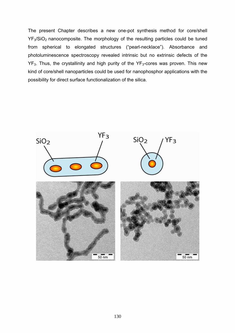
The present Chapter describes a new one-pot synthesis method for core/shell
YF3/SiO2 nanocomposite. The morphology of the resulting particles could be tuned
from spherical to elongated structures (“pearl-necklace”). Absorbance and
photoluminescence spectroscopy revealed intrinsic but no extrinsic defects of the
YF3. Thus, the crystallinity and high purity of the YF3-cores was proven. This new
kind of core/shell nanoparticles could be used for nanophosphor applications with the
possibility for direct surface functionalization of the silica.
130
6- 1 Introduction In recent years, there has been intense interest surrounding the fabrication of
composite micro- and nanoparticles that consist of either organic or inorganic cores
coated with shells of different chemical composition because sometimes bare
nanoparticles can’t be used directly, certain limitations such as toxicity,
hydrophobicity, interactions with oxygen, etc. These problems can often be solved by
intermediate layers or shells (1, 2).
Therefore, derivatization is a pre-requisite for almost any (potential) application of
nanoparticles: Either to stabilize functional cores or to functionalize (activate)
surfaces. Silica is one of the most flexible and robust surfaces which it could be good
choice in this case (its advantages has been already discussed in last chapters) (3-
5).
The core-shell particles often exhibit properties that are substantially different from
those of the templated core (for example, different surface chemical composition,
increased stability, higher surface area, and different magnetic and optical
properties), thus making them attractive from both a scientific and a technological
viewpoint. Fluoride crystalline materials are commonly studied owing to their applications in the
fields of solid state lasers and scintillators. Indeed, their good optical properties
beside their low non-radiative emissions (mainly because of the low cut-off phonon
frequencies) make these materials good host matrices for visible or infrared light
emission and other optical applications. YF3 is an important host crystal for
lanthanide-doped phosphors. It provides a wide band gap (>10 eV) and suitable Y3+-
sites, where trivalent rare-earth elements can be easily substituted without additional
charge compensation. Potential applications include e.g. new laser materials or up-
conversion biolabels (6-9). Furthermore, YF3 is an efficient UV-phosphor in the near
UV-region.
Herein, I report the first one-pot synthesis for YF3/SiO2 nanoparticles by means of a
microemulsion method. In this microemulsion route inverse micelles are used, i.e.,
water nanodroplets are formed in an organic media and used as nanoreactors in order
to control particle size. These nanodroplets are surrounded by a surfactant layer that
limits their size and separates them from the organic compound. The yielded
nanoparticles were characterized by transmission electron microscopy (TEM) and
131
absorption/photoluminescence spectroscopy. It was found, that the morphology of the
resulting particles can be tuned from spherical to elongated “pearl necklace” structures.
The photoluminescence (PL) spectra revealed the presence of intrinsic, but not
extrinsic defects.
6- 2 Experimental section 6- 2- 1 Chemicals All chemicals were purchased from Aldrich in high purity quality and were used as
received. ammonia aqueous solution (33 wt%), cyclohexane, acetone, butanol,
propanol, ethanol from internal sources.
6- 2- 2 Synthesis process of YF3/SiO2 nanocomposite
YF3/SiO2 nanoparticles were prepared in two steps, first YF3 nanoparticles was
synthesized by modification of literature method (10-13). Subsequently, silica
encapsulation has been done within the same reactor (one pot). In a typical
synthesis, a microemulsion was first prepared by mixing 0.5 mL of 0.04 M aqueous
solution of YCl3 and the desired amount of NP-5 in 15 mL of cyclohexane as a
continuous phase in a flask under vigorous stirring at ambient conditions (amount of
surfactant was varied from 1.65 g, low concentration, to 4.22 g, high concentration).
30 min after the microemulsion system was formed, 0.5 mL of aqueous 0.04 M
NH4HF2 was then added directly to the microemulsion with agitation in ambient
condition, the resulting suspension was clear to the eye. After producing YF3
nanoparticles, 0.1 mL ammonia aqueous solution (33wt %) was introduced to the
microemulsion system and 30 min later during vigorous magnetic stirring 0.1 mL
TEOS was added to the system as silica precursor. The silica growth was completed
after 24 h of stirring and then YF3/SiO2 composite particles were precipitated by
adding 1 mL acetone into this colloidal solution followed by washing in sequence with
1-butanol, 1-propanol, and ethanol. For each washing step, followed by
centrifugation, a sonicator bath was used to completely disperse the precipitate in the
corresponding solvent and remove any physically adsorbed molecules from the
132
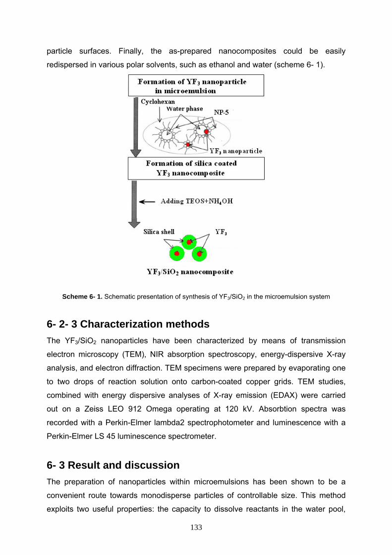
particle surfaces. Finally, the as-prepared nanocomposites could be easily
redispersed in various polar solvents, such as ethanol and water (scheme 6- 1).
Scheme 6- 1. Schematic presentation of synthesis of YF3/SiO2 in the microemulsion system
6- 2- 3 Characterization methods The YF3/SiO2 nanoparticles have been characterized by means of transmission
electron microscopy (TEM), NIR absorption spectroscopy, energy-dispersive X-ray
analysis, and electron diffraction. TEM specimens were prepared by evaporating one
to two drops of reaction solution onto carbon-coated copper grids. TEM studies,
combined with energy dispersive analyses of X-ray emission (EDAX) were carried
out on a Zeiss LEO 912 Omega operating at 120 kV. Absorbtion spectra was
recorded with a Perkin-Elmer lambda2 spectrophotometer and luminescence with a
Perkin-Elmer LS 45 luminescence spectrometer.
6- 3 Result and discussion The preparation of nanoparticles within microemulsions has been shown to be a
convenient route towards monodisperse particles of controllable size. This method
exploits two useful properties: the capacity to dissolve reactants in the water pool,
133
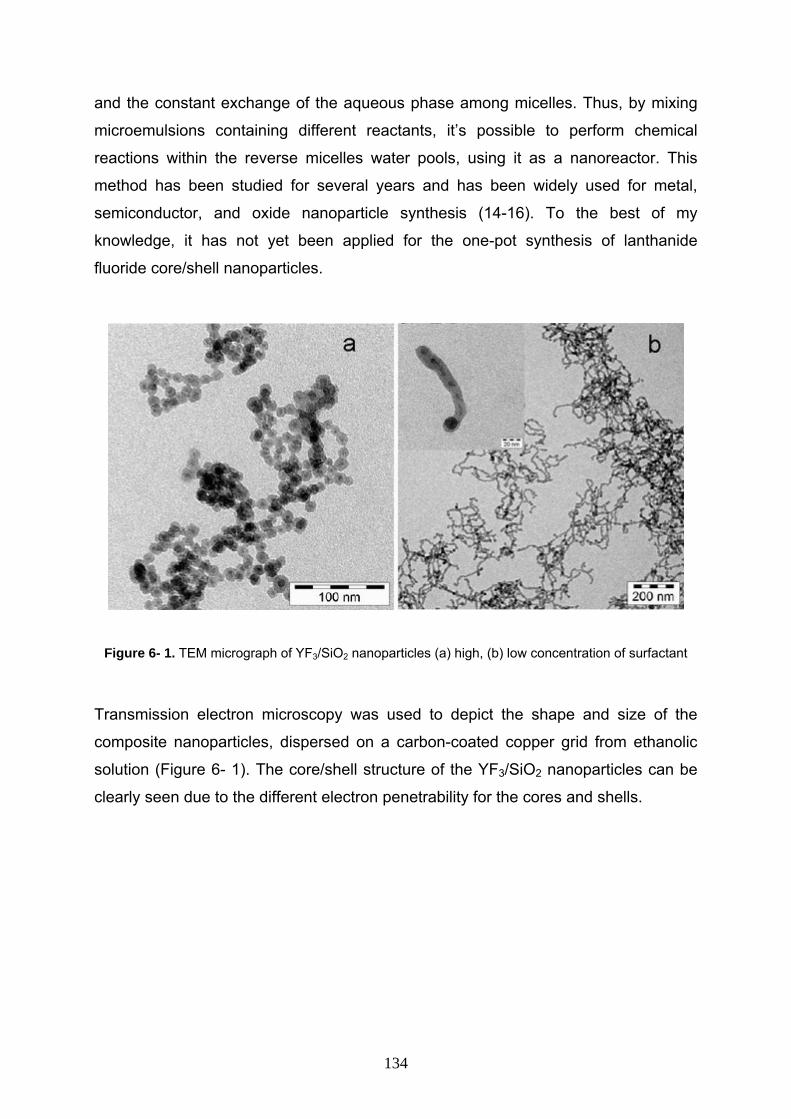
and the constant exchange of the aqueous phase among micelles. Thus, by mixing
microemulsions containing different reactants, it’s possible to perform chemical
reactions within the reverse micelles water pools, using it as a nanoreactor. This
method has been studied for several years and has been widely used for metal,
semiconductor, and oxide nanoparticle synthesis (14-16). To the best of my
knowledge, it has not yet been applied for the one-pot synthesis of lanthanide
fluoride core/shell nanoparticles.
Figure 6- 1. TEM micrograph of YF3/SiO2 nanoparticles (a) high, (b) low concentration of surfactant
Transmission electron microscopy was used to depict the shape and size of the
composite nanoparticles, dispersed on a carbon-coated copper grid from ethanolic
solution (Figure 6- 1). The core/shell structure of the YF3/SiO2 nanoparticles can be
clearly seen due to the different electron penetrability for the cores and shells.
134
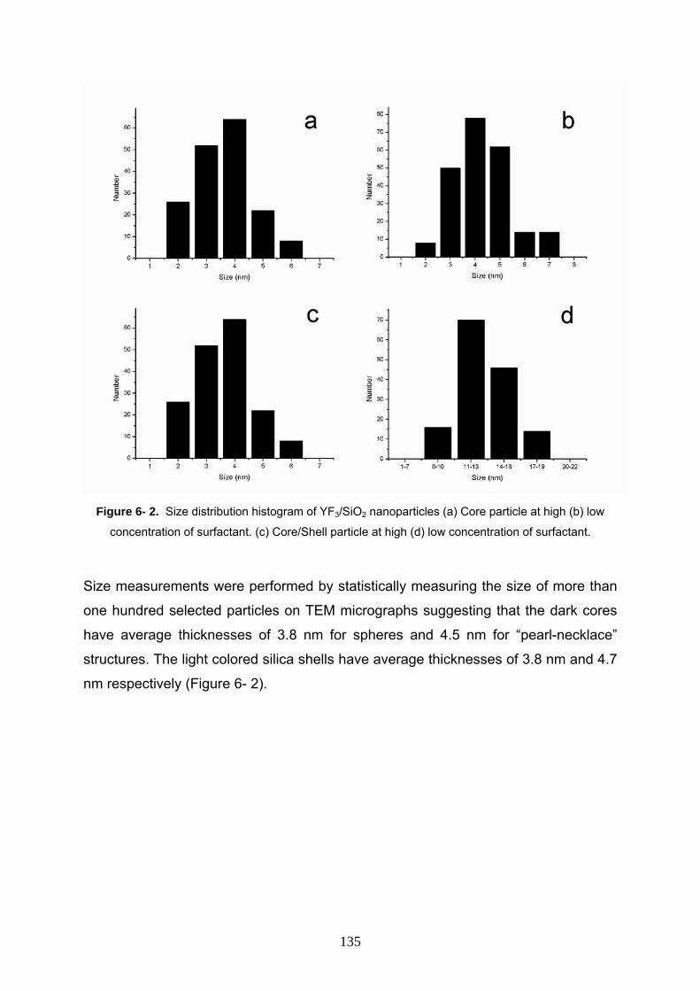
Figure 6- 2. Size distribution histogram of YF3/SiO2 nanoparticles (a) Core particle at high (b) low
concentration of surfactant. (c) Core/Shell particle at high (d) low concentration of surfactant.
Size measurements were performed by statistically measuring the size of more than
one hundred selected particles on TEM micrographs suggesting that the dark cores
have average thicknesses of 3.8 nm for spheres and 4.5 nm for “pearl-necklace”
structures. The light colored silica shells have average thicknesses of 3.8 nm and 4.7
nm respectively (Figure 6- 2).
135
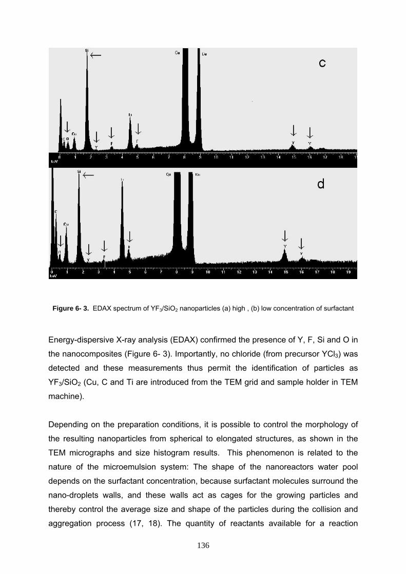
Figure 6- 3. EDAX spectrum of YF3/SiO2 nanoparticles (a) high , (b) low concentration of surfactant
Energy-dispersive X-ray analysis (EDAX) confirmed the presence of Y, F, Si and O in
the nanocomposites (Figure 6- 3). Importantly, no chloride (from precursor YCl3) was
detected and these measurements thus permit the identification of particles as
YF3/SiO2 (Cu, C and Ti are introduced from the TEM grid and sample holder in TEM
machine).
Depending on the preparation conditions, it is possible to control the morphology of
the resulting nanoparticles from spherical to elongated structures, as shown in the
TEM micrographs and size histogram results. This phenomenon is related to the
nature of the microemulsion system: The shape of the nanoreactors water pool
depends on the surfactant concentration, because surfactant molecules surround the
nano-droplets walls, and these walls act as cages for the growing particles and
thereby control the average size and shape of the particles during the collision and
aggregation process (17, 18). The quantity of reactants available for a reaction
136
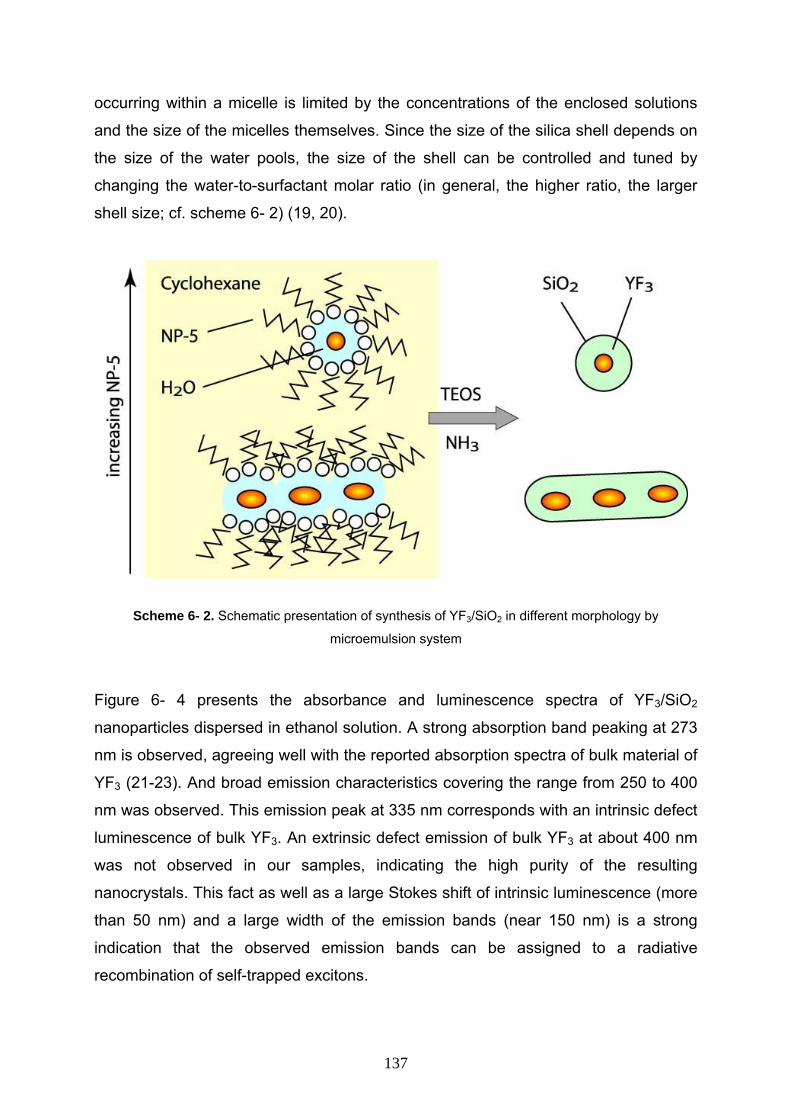
occurring within a micelle is limited by the concentrations of the enclosed solutions
and the size of the micelles themselves. Since the size of the silica shell depends on
the size of the water pools, the size of the shell can be controlled and tuned by
changing the water-to-surfactant molar ratio (in general, the higher ratio, the larger
shell size; cf. scheme 6- 2) (19, 20).
Scheme 6- 2. Schematic presentation of synthesis of YF3/SiO2 in different morphology by
microemulsion system
Figure 6- 4 presents the absorbance and luminescence spectra of YF3/SiO2
nanoparticles dispersed in ethanol solution. A strong absorption band peaking at 273
nm is observed, agreeing well with the reported absorption spectra of bulk material of
YF3 (21-23). And broad emission characteristics covering the range from 250 to 400
nm was observed. This emission peak at 335 nm corresponds with an intrinsic defect
luminescence of bulk YF3. An extrinsic defect emission of bulk YF3 at about 400 nm
was not observed in our samples, indicating the high purity of the resulting
nanocrystals. This fact as well as a large Stokes shift of intrinsic luminescence (more
than 50 nm) and a large width of the emission bands (near 150 nm) is a strong
indication that the observed emission bands can be assigned to a radiative
recombination of self-trapped excitons.
137
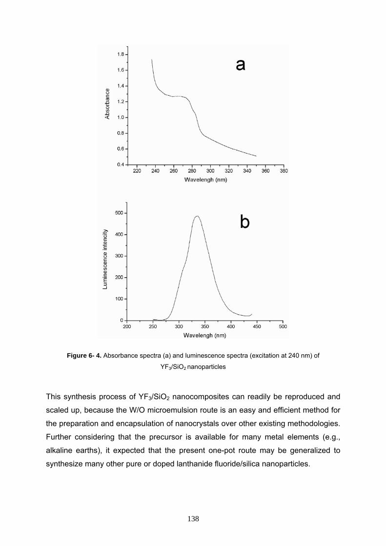
Figure 6- 4. Absorbance spectra (a) and luminescence spectra (excitation at 240 nm) of
YF3/SiO2 nanoparticles
This synthesis process of YF3/SiO2 nanocomposites can readily be reproduced and
scaled up, because the W/O microemulsion route is an easy and efficient method for
the preparation and encapsulation of nanocrystals over other existing methodologies.
Further considering that the precursor is available for many metal elements (e.g.,
alkaline earths), it expected that the present one-pot route may be generalized to
synthesize many other pure or doped lanthanide fluoride/silica nanoparticles.
138
6- 4 Conclusion In summary, a new synthesis method for preparing YF3/SiO2 nanocomposite in a
one-pot system was developed. This method uses water-in-oil microemulsions in
which monodisperse YF3 nanocrystals were synthesized in the water nano-pool and
subsequently silica shells were produced by the controlled hydrolysis of tetraethyl
orthosilicate (TEOS) in the water nanodroplets within the same rector. However, the
dependence of the particle size on the surfactant concentration, and hence on the
micelle size, seems to influence the water pool size of the microemulsion and
predominantly determines the size and shape of the resulting nanoparticles. Finally,
one interesting point of this chapter is that the luminescence source of YF3/SiO2
nanocomposite was found to be intrinsic and not extrinsic.
139
References 1- Y. T. Yu and P.Mulvaney, Mater. Trans., JIM, 2004, 45, 964.
2- T.Nann, Chem. Commun., 2005, 1735.
3- H. Ow, D. R. Larson,M. Srivastava, B. A. Baird, W. W. Webb, U. Wiesner, Nano
Lett., 2005, 5, 113.
4- C. Graf, D. L. J. Vossen, A. Imhof, A. Van Blaaderen, Langmuir, 2003, 19, 6693.
5- T. Nann, P. Mulvaney, Angew. Chem., Int. Ed., 2004, 43, 5393.
6- Y.-W. Zhang, X. Sun, R. Si, L.-P. You, C.-H. Yan, J. Am. Chem. Soc., 2005, 127,
3260.
7- M. M. Lage, A. Righi, F. M. Matinaga, J.-Y. Gesland, R. L. Moreira, J. Phys.:
Condens. Matter, 2004, 16, 3207.
8- K. J. Guedes, K. Krambrock, J. Y. Gesland, J. Phys. Chem. Solids, 2001, 62, 485.
9- K. J. Guedes, K. Krambrock, J. Y. Gesland, J. Phys.: Condens. Matter, 1999, 11,
7211.
10- J. L. Lemyre, A. M. Ritcey, Chem. Mater., 2005, 17, 3040.
11- H. Huang, G. Q. Xu, W. S. Chin, L. M. Gan, C. H. Chew, Nanotechnology, 2002,
13, 318.
12- M. H. Lee, S. G. Oh, S. C. Yi, J. Colloid Interface Sci., 2000, 226, 65.
13- D. G. Shchukin, G. B. Sukhorukov, Langmuir, 2003, 19, 4427.
14- R. D. Tilley, J. H. Warner, K. Yamamoto, I. Matsui, H. Fujimori, Chem. Commun.,
2005, 1833.
15- C. Liu, B. Zou, A. J. Rondinone, Z. J. Zhang, J. Phys. Chem. B, 2000, 104, 1141.
16- E. Stathatos, P. Lianos, F. Del Monte, D. Levy, D. Tsiourvas, Langmuir, 1997, 13,
4295.
17- S. Santra, R. Tapec, N. Theodoropoulou, J. Dobson, A. Hebard, W. Tan,
Langmuir, 2001, 17, 2900.
18- P.A.Dresco, V. S.Zaitsev, R. J. Gambino andB. Chu, Langmuir, 1999, 15, 1945.
19- T. Mokari, H. Sertchook, A. Aharoni, Y. Ebenstein, D. Avnir,U. Banin, Chem.
Mater., 2005, 17, 258.
20- F. Teng, Z. Tian, G. Xiong, Z. Xu, Catal. Today, 2004, 93, 651.
21- V. Pankratov, M. Kirm, H. von Seggern, J. Lumin., 2005, 113, 143.
22- J. W. Stouwdam, G. A. Hebbink, J. Huskens, F. C. J. M. van Veggel, Chem.
Mater., 2003, 15, 4604.
23- J. Adam, Chem. Rev., 2002, 102, 2461.
140
Summary This dissertation focuses on the development of colloidal synthetic approaches for
silica encapsulation of nanocrystals as well as synthesis of hollow silica nanospheres
and one-pot synthesis of silica coated nanocomposites. A series of experiments was
performed which different nanoparticles were silica coated via microemulsion rout.
The nanocomposites prepared were characterized by TEM, EDAX, SAED, XRD,
absorption and luminescence spectroscopy.
Luminescent semiconductor nanocrystals attracted increasing interest over the past
several years, because of their intrinsic and size dependent optical properties. There
has been a tremendous focus on the potential applications of these particles in areas
such as tunable LEDs, QD lasers, luminescent materials and biolabeling.
However, highly luminescent and photostable CdSe/ZnS core/shell quantum dots are
not water dispersible because of their hydrophobicity. In the present work to create
water dispersible quantum dots by an appropriate surface functionalization,
monodispersed silica-coated CdSe/ZnS were synthesized by using the W/O
microemulsion of NP-5/ Cyclohexan/ Water system. By hydrolysis of TEOS with
ammonia in the presence of QDs, the silica coated nanoparticles were obtained in
the microemulsion. In the composite nanoparticle, only single QD was located at the
center of a spherical silica particle. The thickness of silica layer was 15 nm.
Elucidating the coating mechanism was attempted. Possible mechanisms include a
phase transfer by ligand exchange and a surfactant-supported mechanism. It was not
possible to elucidate the encapsulation mechanism completely, but the experimental
results point in the direction of a ligand-exchange/phase-transfer mechanism.
I believe I have developed a simple general approach for creating nanocomposites
with complex morphologies which can be used for a variety of materials, such as
CdSe, etc. Therefore for prove this generality PbSe and YV(0.7)P(0.3)O4:Eu3+, Bi3+ has
been chosen for encapsulation. In order to prevent the dissolution of the PbSe cores,
various amines were tested as catalysts for the hydrolysis and condensation of TEOS
and it was recognized that dimethylamine would be best choice in this case. Also I
selected YV(0.7)P(0.3)O4:Eu3+, Bi3+ as the phosphor core and silica shell to obtain the
core/shell structured YV(0.7)P(0.3)O4:Eu3+, Bi3+/SiO2 materials via the microemulsion
process and characterize the structure, morphology, and photoluminescent
141
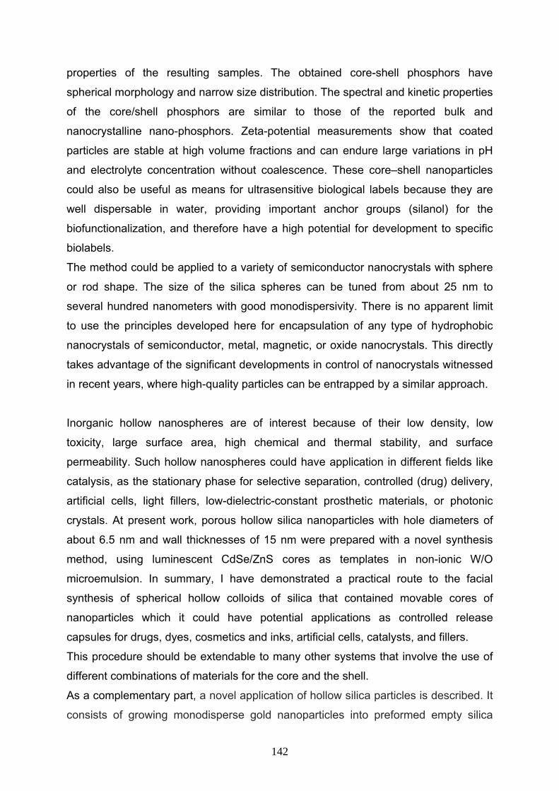
properties of the resulting samples. The obtained core-shell phosphors have
spherical morphology and narrow size distribution. The spectral and kinetic properties
of the core/shell phosphors are similar to those of the reported bulk and
nanocrystalline nano-phosphors. Zeta-potential measurements show that coated
particles are stable at high volume fractions and can endure large variations in pH
and electrolyte concentration without coalescence. These core–shell nanoparticles
could also be useful as means for ultrasensitive biological labels because they are
well dispersable in water, providing important anchor groups (silanol) for the
biofunctionalization, and therefore have a high potential for development to specific
biolabels.
The method could be applied to a variety of semiconductor nanocrystals with sphere
or rod shape. The size of the silica spheres can be tuned from about 25 nm to
several hundred nanometers with good monodispersivity. There is no apparent limit
to use the principles developed here for encapsulation of any type of hydrophobic
nanocrystals of semiconductor, metal, magnetic, or oxide nanocrystals. This directly
takes advantage of the significant developments in control of nanocrystals witnessed
in recent years, where high-quality particles can be entrapped by a similar approach.
Inorganic hollow nanospheres are of interest because of their low density, low
toxicity, large surface area, high chemical and thermal stability, and surface
permeability. Such hollow nanospheres could have application in different fields like
catalysis, as the stationary phase for selective separation, controlled (drug) delivery,
artificial cells, light fillers, low-dielectric-constant prosthetic materials, or photonic
crystals. At present work, porous hollow silica nanoparticles with hole diameters of
about 6.5 nm and wall thicknesses of 15 nm were prepared with a novel synthesis
method, using luminescent CdSe/ZnS cores as templates in non-ionic W/O
microemulsion. In summary, I have demonstrated a practical route to the facial
synthesis of spherical hollow colloids of silica that contained movable cores of
nanoparticles which it could have potential applications as controlled release
capsules for drugs, dyes, cosmetics and inks, artificial cells, catalysts, and fillers.
This procedure should be extendable to many other systems that involve the use of
different combinations of materials for the core and the shell.
As a complementary part, a novel application of hollow silica particles is described. It
consists of growing monodisperse gold nanoparticles into preformed empty silica
142
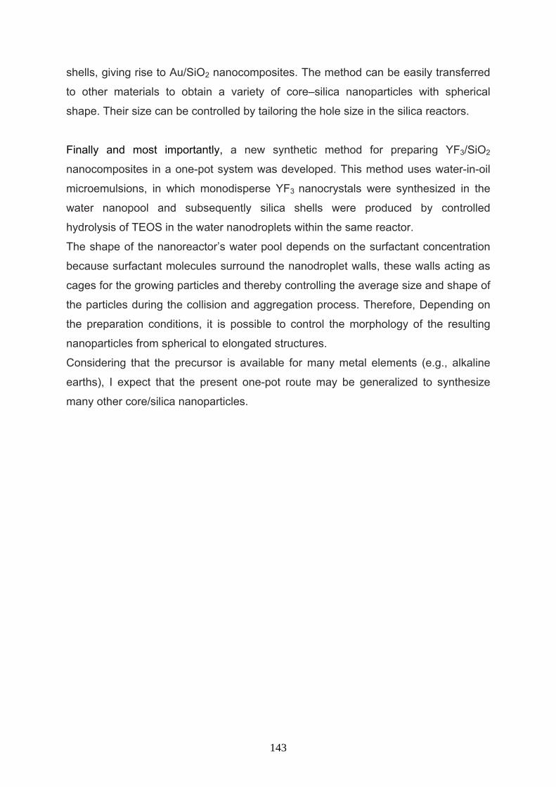
shells, giving rise to Au/SiO2 nanocomposites. The method can be easily transferred
to other materials to obtain a variety of core–silica nanoparticles with spherical
shape. Their size can be controlled by tailoring the hole size in the silica reactors.
Finally and most importantly, a new synthetic method for preparing YF3/SiO2
nanocomposites in a one-pot system was developed. This method uses water-in-oil
microemulsions, in which monodisperse YF3 nanocrystals were synthesized in the
water nanopool and subsequently silica shells were produced by controlled
hydrolysis of TEOS in the water nanodroplets within the same reactor.
The shape of the nanoreactor’s water pool depends on the surfactant concentration
because surfactant molecules surround the nanodroplet walls, these walls acting as
cages for the growing particles and thereby controlling the average size and shape of
the particles during the collision and aggregation process. Therefore, Depending on
the preparation conditions, it is possible to control the morphology of the resulting
nanoparticles from spherical to elongated structures.
Considering that the precursor is available for many metal elements (e.g., alkaline
earths), I expect that the present one-pot route may be generalized to synthesize
many other core/silica nanoparticles.
143
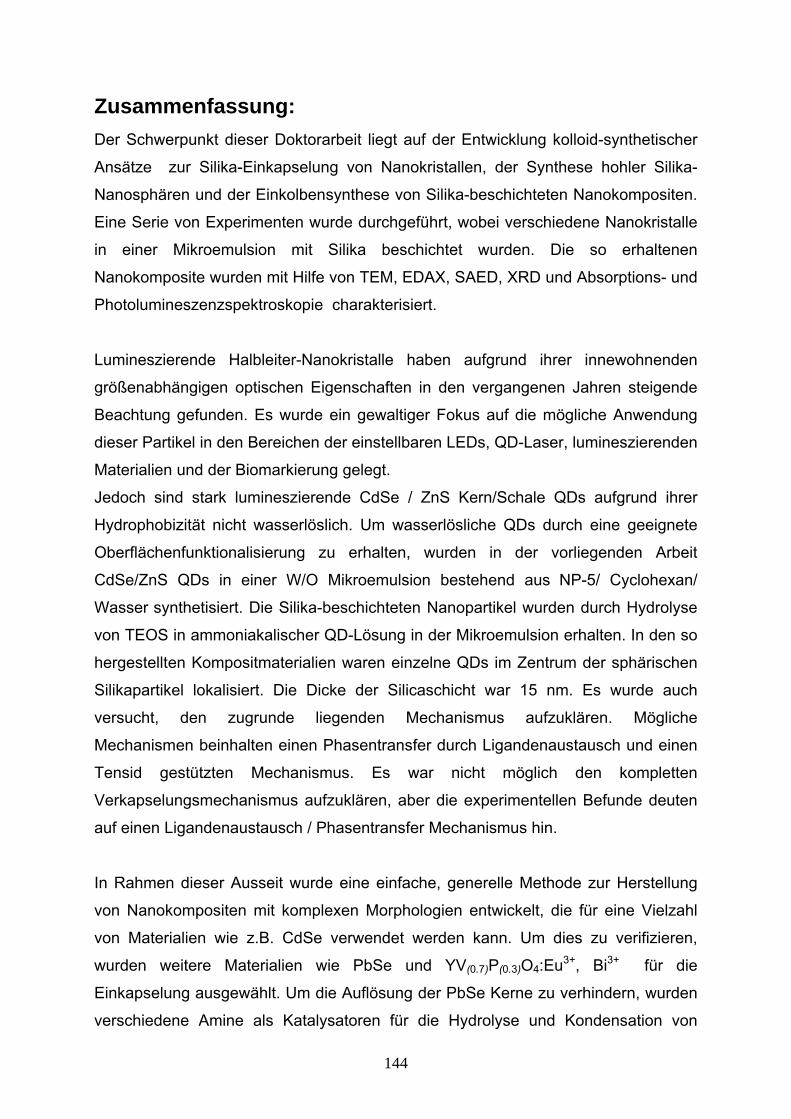
Zusammenfassung: Der Schwerpunkt dieser Doktorarbeit liegt auf der Entwicklung kolloid-synthetischer
Ansätze zur Silika-Einkapselung von Nanokristallen, der Synthese hohler Silika-
Nanosphären und der Einkolbensynthese von Silika-beschichteten Nanokompositen.
Eine Serie von Experimenten wurde durchgeführt, wobei verschiedene Nanokristalle
in einer Mikroemulsion mit Silika beschichtet wurden. Die so erhaltenen
Nanokomposite wurden mit Hilfe von TEM, EDAX, SAED, XRD und Absorptions- und
Photolumineszenzspektroskopie charakterisiert.
Lumineszierende Halbleiter-Nanokristalle haben aufgrund ihrer innewohnenden
größenabhängigen optischen Eigenschaften in den vergangenen Jahren steigende
Beachtung gefunden. Es wurde ein gewaltiger Fokus auf die mögliche Anwendung
dieser Partikel in den Bereichen der einstellbaren LEDs, QD-Laser, lumineszierenden
Materialien und der Biomarkierung gelegt.
Jedoch sind stark lumineszierende CdSe / ZnS Kern/Schale QDs aufgrund ihrer
Hydrophobizität nicht wasserlöslich. Um wasserlösliche QDs durch eine geeignete
Oberflächenfunktionalisierung zu erhalten, wurden in der vorliegenden Arbeit
CdSe/ZnS QDs in einer W/O Mikroemulsion bestehend aus NP-5/ Cyclohexan/
Wasser synthetisiert. Die Silika-beschichteten Nanopartikel wurden durch Hydrolyse
von TEOS in ammoniakalischer QD-Lösung in der Mikroemulsion erhalten. In den so
hergestellten Kompositmaterialien waren einzelne QDs im Zentrum der sphärischen
Silikapartikel lokalisiert. Die Dicke der Silicaschicht war 15 nm. Es wurde auch
versucht, den zugrunde liegenden Mechanismus aufzuklären. Mögliche
Mechanismen beinhalten einen Phasentransfer durch Ligandenaustausch und einen
Tensid gestützten Mechanismus. Es war nicht möglich den kompletten
Verkapselungsmechanismus aufzuklären, aber die experimentellen Befunde deuten
auf einen Ligandenaustausch / Phasentransfer Mechanismus hin.
In Rahmen dieser Ausseit wurde eine einfache, generelle Methode zur Herstellung
von Nanokompositen mit komplexen Morphologien entwickelt, die für eine Vielzahl
von Materialien wie z.B. CdSe verwendet werden kann. Um dies zu verifizieren,
wurden weitere Materialien wie PbSe und YV(0.7)P(0.3)O4:Eu3+, Bi3+ für die
Einkapselung ausgewählt. Um die Auflösung der PbSe Kerne zu verhindern, wurden
verschiedene Amine als Katalysatoren für die Hydrolyse und Kondensation von
144
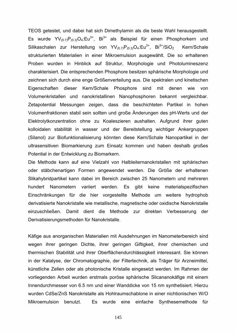
TEOS getestet, und dabei hat sich Dimethylamin als die beste Wahl herausgestellt.
Es wurde YV(0.7)P(0.3)O4:Eu3+, Bi3+ als Beispiel für einen Phosphorkern und
Silikaschalen zur Herstellung von YV(0.7)P(0.3)O4:Eu3+, Bi3+/SiO2 Kern/Schale
strukturierten Materialien in einer Mikroemulsion ausgewählt. Die so erhaltenen
Proben wurden in Hinblick auf Struktur, Morphologie und Photolumineszenz
charakterisiert. Die entsprechenden Phosphore besitzen sphärische Morphologie und
zeichnen sich durch eine enge Größenverteilung aus. Die spektralen und kinetischen
Eigenschaften dieser Kern/Schale Phosphore sind mit denen wie von
Volumenkristallen und nanokristallinen Nanophosphoren bekannt vergleichbar.
Zetapotential Messungen zeigen, dass die beschichteten Partikel in hohen
Volumenfraktionen stabil sein sollten und große Änderungen des pH-Werts und der
Elektrolytkonzentration ohne zu Koaleszieren aushalten. Aufgrund ihrer guten
kolloidalen stabilität in wasser und der Bereitstellung wichtiger Ankergruppen
(Silanol) zur Biofunktionalisierung könnten diese Kern/Schale Nanopartikel in der
ultrasensitiven Biomarkierung zum Einsatz kommen und haben deshalb großes
Potential in der Entwicklung zu Biomarkern.
Die Methode kann auf eine Vielzahl von Halbleiternanokristallen mit sphärischen
oder stäbchenartigen Formen angewendet werden. Die Größe der erhaltenen
Slikahybridpartikel kann dabei im Bereich zwischen 25 Nanometern und mehreren
hundert Nanometern variiert werden. Es gibt keine materialspezifischen
Einschränkungen für die hier vorgestellte Methode um weitere hydrophob
derivatisierte Nanokristalle wie metallische, magnetische oder oxidische Nanokristalle
einzuschließen. Damit dient die Methode zur direkten Verbesserung der
Derivatisierungsmethoden für Nanokristalle.
Käfige aus anorganischen Materialien mit Ausdehnungen im Nanometerbereich sind
wegen ihrer geringen Dichte, ihrer geringen Giftigkeit, ihrer chemischen und
thermischen Stabilität und ihrer Oberflächendurchlässigkeit interessant. Sie können
in der Katalyse, der Chromatographie, der Filtertechnik, als Träger für Arzneimittel,
künstliche Zellen oder als photonische Kristalle eingesetzt werden. Im Rahmen der
vorliegenden Arbeit wurden erstmals poröse sphärische Slicananokäfige mit einem
Innendurchmesser von 6.5 nm und einer Wanddicke von 15 nm synthetisiert. Hierzu
wurden CdSe/ZnS Nanokristalle als Hohlraumschablone in einer nichtionischen W/O
Mikroemulsion benutzt. Es wurde eine einfache Synthesemethode für
145
Silicananokäfige vorgestellt, bei der die ursprünglichen Kernnanokristalle entfernt
werden können. Diese Käfige könnten zum kontrollierten und dosierten verabreichen
von Farbstoffen, Medikamenten, Kosmetika und Tinten, als künstliche Modelsysteme
für Zellen, als Katalysatoren und Filter eingesetzt werden.
Die vorgestellte Methode kann um viele weitere Systeme erweitert werden, indem
sowohl Kern als auch Schalenmaterial variiert werden.
Als beispielhafte Anwendung wurden die oben beschriebenen Silicakäfige benutzt
um in ihnen Goldnanokristalle herzustellen. Hierbei entstand ein sehr monodisperses
Au/SiO2 Nanokompositmaterial. Diese Technik kann ebenfalls leicht um weitere
Materialien erweitert werden um eine Vielzahl von Kern/Slikaschale Materialien
herzustellen.
Schließlich wurde eine neuartige Darstellungsmethode für YF3/SiO2
Nanokompositmaterialien entwickelt, bei der das YF3 als Zwischenstufe nicht
gewonnen werden muss. Hierzu wurde eine Wasser in Öl Mikroemulsion benutzt, bei
der die YF3-Nanokristalle in den Wassertropfen mit Nanometerausdehnungen
kristallisierten. Das schrittweise Aufwachsen der Silikaschale wurde durch die
langsame Hydrolyse von TEOS in denselben Wassertropfen erreicht. Die äußere
Form dieser Nanoreaktionszentren wird durch die Konzentration des zugefügten
Detergenz bestimmt, das die Grenzschicht zwischen polarem und unpolarem
Medium bildet. Diese Grenzschicht dient als Schablone während des Wachstums der
Kristalle. Daher ist es möglich durch geeigneter Wahl der Darstellungsbedingungen
die Morphologie der Nanokristalle zu bestimmen. Es wurden sphärische und
stäbchenförmige Kristalle erhalten. Unter der Vorraussetzung, das Vorstufen
erhältlich sind, kann die vorgestellte Methode als generelle Darstellungsvariante für
Kern/Silicaschale Nanopartikel betrachtet werden.
146
VITAE
Birth Date: June 28th 1979, Tehran, Iran
1997-2001 B.Sc., Tabriz University, Tabriz, Iran
Chemistry (Pure Chemistry)
2001-2003 M.Sc., Sharif University of Technology, Tehran, Iran
Chemistey (Physical Chemistry)
147
Publication M. Darbandi, R. Thomann, T. Nann, “Single Quantum dots in silica spheres by
microemulsion synthesis” Chem. Mater. 2005, 17, 5720-5725
M. Darbandi, T. Nann, “One-pot synthesis of YF3@silica core/shell
nanoparticles” Chem. Commun, 2006, 776-778.
M. Darbandi, W. Lu, J. Fang, T. Nann “ Silica Encapsulation of
Hydrophobically Ligated PbSe Nanocrystals” Langmuir, 2006, 22, 4371-4375
M. Darbandi, W. Hoheisel, T. Nann, “Silica coated, water dispersible and
photoluminescent Y (V, P) O4:Eu3+, Bi3+ nanophosphors ” Nanotechnology,
2006, 17, 4168–4173.
M. Darbandi, R. Thomann, T. Nann, “Hollow silica nanospheres: In-situ, semi
in-situ and two-step synthesis” Chem. Mater. 2007, 19, 1700-1703.
S. Cavaliere-Jaricot, M. Darbandi, T. Nann, “Au/silica nanoparticles by reverse
synthesis of cores in hollow silica shells” Chem. Commun, 2007, 2031-2033
S. Cavaliere-Jaricot, M. Darbandi, E. Kuçur, T. Nann, “Silica coated
nanoparticles: a new tool for the electrochemical and optical glucuse
detection” Microchim. Acta. 2007, Accepted
U. Pyell, M. Darbandi, W. Bücking, T. Nann, H. Jungclas, “Electromigrative
characterization of semiconductor nanocrystals encapsulated with amorphous
silicium dioxide” Microchim. Acta. 2007, Accepted
M. Darbandi, S. Cavaliere-Jaricot, E. Corcoran, J. Riegler, T. Nann, “More
investigation on the synthesis, functionalization and characterization of
CdSe/ZnS/SiO2 nanocomposites” Submitted
148
M. Darbandi, W. Büking, T. Nann, “Preparation and colloidal stability of silica
encapsulated nanoparticles” , Encyclopedia of Nanoscience and
Nanotechnology, American Scientific Publishers, Submitted
K. Eggenberger, A. Merkoulov, M. Darbandi, T. Nann, P. Nick, “Direct
immunofluorescence of plant microtubules based on semiconductor
nanocrystals ”, Submitted
Conference presentation “Biocompatible QD’s-silica particle” as poster by Masih Darbandi, Thomas
Nann in Nanotechnology in biodiagnostics and analytics conference, Grenoble, France, June 29th and 30th 2005.
“Quantum Dots with silica shells” as oral presentation by Masih Darbandi,
Thomas Nann in International symposium on colloidal quantum dots for
biomedical applications and their safety, University of Kobe, Kobe, Japan, 26.
November 2005.
“Silica coated nanoparticles by microemulsion system” as oral presentation by
Masih Darbandi, Thomas Nann, in NANAX2 Nanoscience with nanocrystals
second International conference on colloidal semiconductor and metal
nanocrystals, Grenoble, France, January 7-10th 2006.
“Ways for preparation of different core/shell silica nanospheres” as oral
presentation by Masih Darbandi, Thomas Nann, in Nanoparticles: New
Opportunities and Challenges for Colloid Scientists, University of Warwick ,
Coventry , United Kingdom, March 28-30th 2007
149

Aknowledgement I take this opportunity to thank all of them who supported me directly, indirectly,
technically or morally.
Initially, I am very grateful to my advisor Professor Thomas Nann, for continuous
guidance, support and encouragement throughout this study.
I thank my committee, Professor Rühe, Professor Urban and Professor Zacharias, for
helpful discussions and suggestions.
I deeply appreciate the help by Dr. Ralf Thomann in carrying out TEM, SAED, EDAX
measurements and Dr. Jürgen Riegler, Prof. Jiye Fang, Dr. Werner Hoheisel for
providing core particles.
I would like to thank Dr. Sara Cavaliere-Jaricot for scientific help during preparation of
chapter 5.
I acknowledge German government for the financial support for this research.
I would like to thank all present and past members and affiliates of the Nann group
for their support, advice, and generally for being a cool bunch of people, especially
Erol Kuçur, Oliver Ehlert, Shu Xu.
I would like to thank Dr. Jürgen Riegler, Dr. Alexei Merkoulov and Frank Stefan
Riehle for German translation of summary.
It is my pleasure to express gratitude towards my parents, brother and sister for
continuous moral support.
Finally, and most importantly, I thank my wife, Nazila Golmohammadi, for more
things than space allows, but mostly for her love and support.
150

Declaration
The material contained in this thesis is the result of my own work and all sources of
information as well as the results obtained in collaboration with other people are
pointed out.
This dissertation has not been submitted in whole or in part for the award of a degree
at this or any other university.
Freiburg, 2007
Masih Darbandi
151