Embed Size (px)
Citation preview

Doc. # 01-13-003B
Vastex International, Inc. 7 Emery Street Bethlehem, PA 18015 Phone# 610 625-2702 Fax# 610 625-2775 Web Site: www.vastex.com E-Mail: [email protected]
Vastex Manual Press Registration System
Assembly and Operations Manual
Contents Pg. #
Introduction 2
Component Identification 2-3
Pallet Jig Assembly (Manual Rear Clamp) 4
Pallet Jig Assembly (Manual Side Clamp) 5
Pin Board Assembly 6
Operation 7-10

Doc. # 01-13-003B
1) The Pin Board is designed to be usedwith many different exposing units.The two most popular versions areshown on the left. The VRS Pin Boardhas a placement grid attached to theface. Your specific pin board may bedifferent than those shown.
Thank you for purchasing a Vastex VRS System. Vastex has been designing and building printing equipment since 1960. We have knowledge and experience, and are proud to supply the printing industry with quality equipment at an affordable price. You can be confident your purchase will give you years of trouble free service.
Registrations systems are a method for accurately locating art work onto screens and into your printer. VRS systems are available for manual and automatic presses. This manual covers the setup and operation of your registration system.
•9/16” wrench
•7/16” wrench
•1/4” Nut Driver
•Roll of Double Sided Tape (Operation method 1)
Illustrations of components within this manual may be shown different than your actual components.
1
Rear Clamp Version
2
Side Clamp Version
2) The Pallet Jig is used to accuratelyposition exposed screens onto yourpress.
Component ID
Introduction
Tools Required
Pg. 2
Doc. # 01-13-003B
4) The registration pins are provided to fasten the clearcarrier sheets to the pin board. The registration pinsare anchor points for the setup sheets, allowing forprecise placement of art work onto your screens.
3
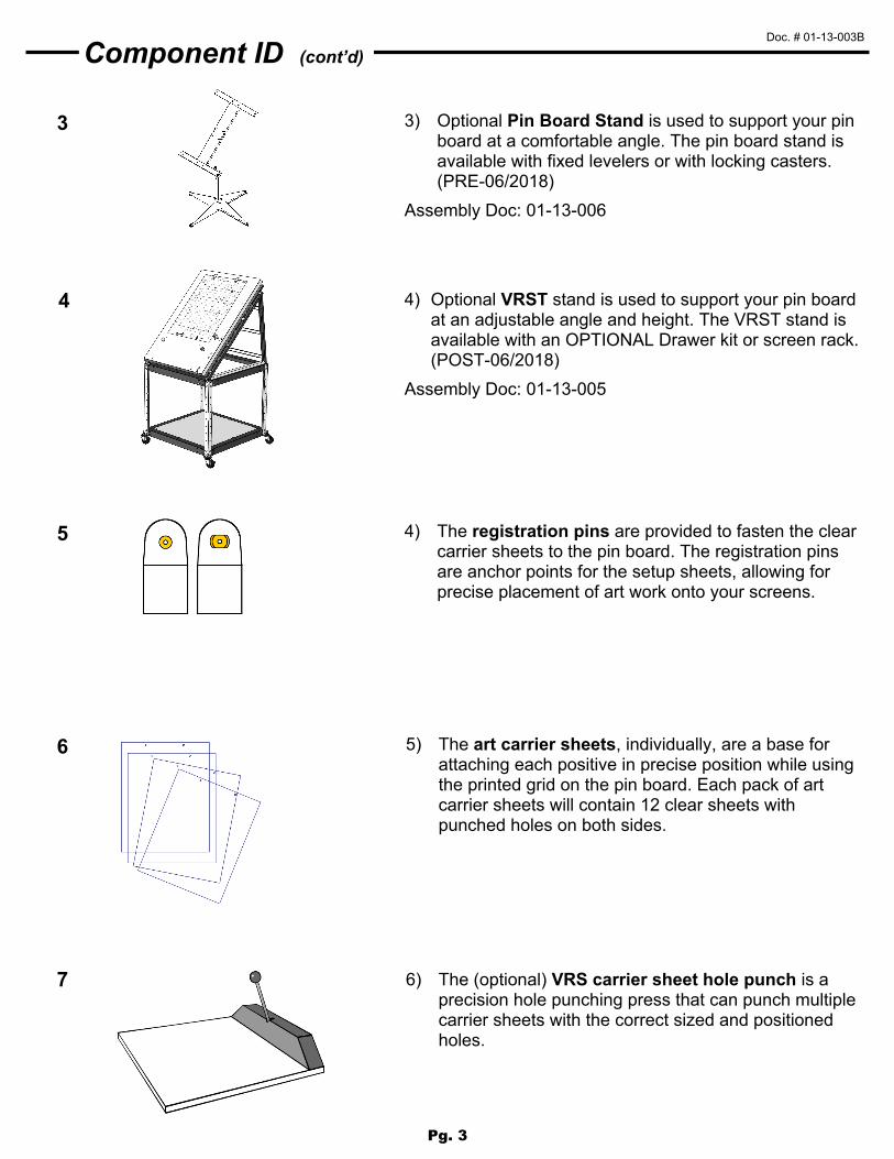
5) The art carrier sheets, individually, are a base forattaching each positive in precise position while usingthe printed grid on the pin board. Each pack of artcarrier sheets will contain 12 clear sheets withpunched holes on both sides.
6) The (optional) VRS carrier sheet hole punch is aprecision hole punching press that can punch multiplecarrier sheets with the correct sized and positionedholes.
5
6
7
3) Optional Pin Board Stand is used to support your pinboard at a comfortable angle. The pin board stand isavailable with fixed levelers or with locking casters.(PRE-06/2018)
Assembly Doc: 01-13-006
Component ID (cont’d)
4 4) Optional VRST stand is used to support your pin boardat an adjustable angle and height. The VRST stand isavailable with an OPTIONAL Drawer kit or screen rack.(POST-06/2018)
Assembly Doc: 01-13-005
Pg. 3

Doc. # 01-13-003B
3d 3c
3b 3a
Pallet Jig Assembly—Rear Clamp
Square nut
Washer
3/8-16 x 1-3/4” bolt
1” Jig Stop
Pallet Jig
3/8-16 x 3/4” bolt
Pallet Jig
3/4” Jig Stop
Lock washer
Washer
3/4” Jig Stops
1” Jig Stop
2) Install and leave loose.
− (1) 1” Tall Jig Stop with 3/8-16 x 1-3/4” bolt, washer, and square nut as shown.
This stop centers the screen on the Jig. Mark center on your screen, align it with the center mark on the Pallet Jig, and set
the 1” Jig stop against the screen.
Then tighten with 9/16” wrench.
1) Install and tighten.
− (2) 3/4” Tall Jig Stops with 3/8-16 x 3/4” bolts, lock washers, and washers.
Tighten well using 9/16” wrench
3) Install.
− (2) Clamps, springs, and thumb screws as shown. The clamps hook into the bottom of the Pallet Jig. See Illustrations 3a-3d below.
Step 1 Step 2
Pg. 4
Doc. # 01-13-003B
1” Jig Stop
3d 3c
3b 3a
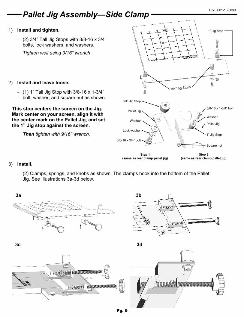
Pallet Jig Assembly—Side Clamp
Square nut
Washer
3/8-16 x 1-3/4” bolt
1” Jig Stop
Pallet Jig
3/8-16 x 3/4” bolt
Pallet Jig
3/4” Jig Stop
Lock washer
Washer
3) Install.
− (2) Clamps, springs, and knobs as shown. The clamps hook into the bottom of the PalletJig. See Illustrations 3a-3d below.
Step 1 (same as rear clamp pallet jig)
Step 2 (same as rear clamp pallet jig)
2) Install and leave loose.
− (1) 1” Tall Jig Stop with 3/8-16 x 1-3/4”bolt, washer, and square nut as shown.
This stop centers the screen on the Jig. Mark center on your screen, align it with the center mark on the Pallet Jig, and set
the 1” Jig stop against the screen.
Then tighten with 9/16” wrench.
1) Install and tighten.
− (2) 3/4” Tall Jig Stops with 3/8-16 x 3/4”bolts, lock washers, and washers.
Tighten well using 9/16” wrench
Pg. 5

Doc. # 01-13-003B
7 1/16” 9” 8 9/16”
2 1
7/3
2”
Pin Board Assembly
3) Install and leave loose
− (1) 1” Tall Jig Stop with 3/8-16 x 1-3/4” bolt, washer, and square nut as shown.
This stop centers the screen on the Jig. Mark center on your screen, align it with the center mark on the Pin Board, and
set the 1” Jig stop against the screen.
Then tighten with 9/16” wrench
2) Install and tighten.
− (2) 3/4” Tall Jig Stops with 3/8-16 x 3/4” bolts, lock washers, and washers. There are 2 positions. Select appropriate holes for your screen size.
Then tighten with 9/16” wrench.
1) Install and tighten.
− (4) Rubber Feet, #10 washers, and 8-32 x 1/2” sheet metal screws
Tighten well using 1/4” wrench
4) Install Pins and Tabs (Normally installed at factory)
Locations shown on right. Side clamp and Rear Clamp Pin Boards use the same locations. Dimensions are to the center of the pins. Oblong pin on right.
#10 washer
Rubber foot
8-32 x 1/2” sheet metal screw
3/4” Jig Stops
1” Jig Stop
For 24” Tall screen
For 31” Tall screen
Pin Board Assembly
Pin and Tab Locations
Square nut
Washer
3/8-16 x 1-3/4” bolt
1” Jig Stop
Pin board
Step 3 Step 2
3/8-16 x 3/4” bolt
Pin board
3/4” Jig Stop
Lock washer
Washer
Pg. 6

Doc. # 01-13-003B
1-2
3
4
Operation
This section outlines the operating methods for the Vastex VRS
Using the Pinboard (Method 1: For any exposing unit)
1) 1) Exposure systems without the VRS pin stopswill use the art alignment grid and pins on thePin Board. Place the carrier sheet onto the pinson the Pin Board. Align and tape your positiveto the carrier sheet. Repeat this for all thepositives for the job you are printing. When allthe colors are on individual carrier sheets,choose the appropriate screens for your job.
2) The carrier sheets will be attached to thescreens with double sided tape or tape facingsticky side up from the underside of the carriersheets.
3) Carefully place the screen against the pin stopsat the bottom and slide the screen over to theside stop (make sure not to move the carriersheet and positive out of position). Press thescreen to the carrier sheet to stick the tape tothe screen. Remove the screen from the PinBoard and make sure the carrier sheet andpositive is secure to the shirt side of thescreen. Be careful not to tear the pin holes.Place the screen with the aligned positive ontoyour exposure system and expose.
4) After exposure, remove the carrier sheet andpositive from the screen. Wash and developthe emulsion as normal. When the screen isdry, prepare for installation into your press(tape and block out).
The following page shows how to use the VRS with a Vastex Expos-It equipped with
pins/tabs and (optional) 3rd side stop.
Pg. 7
Doc. # 01-13-003B
1
2
3
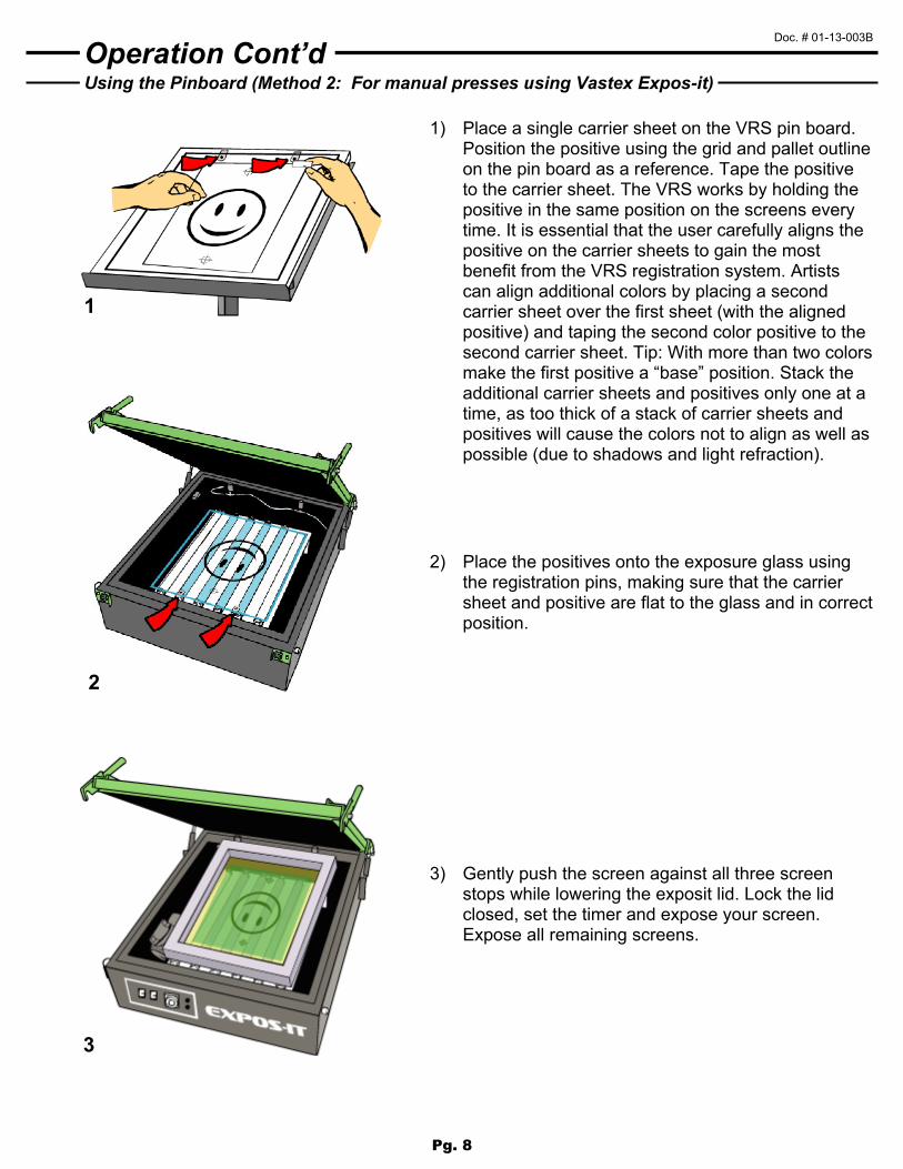
Using the Pinboard (Method 2: For manual presses using Vastex Expos-it)
Operation Cont’d
1) Place a single carrier sheet on the VRS pin board. Position the positive using the grid and pallet outline on the pin board as a reference. Tape the positive to the carrier sheet. The VRS works by holding the positive in the same position on the screens every time. It is essential that the user carefully aligns the positive on the carrier sheets to gain the most benefit from the VRS registration system. Artists can align additional colors by placing a second carrier sheet over the first sheet (with the aligned positive) and taping the second color positive to the second carrier sheet. Tip: With more than two colors make the first positive a “base” position. Stack the additional carrier sheets and positives only one at a time, as too thick of a stack of carrier sheets and positives will cause the colors not to align as well as possible (due to shadows and light refraction).
2) Place the positives onto the exposure glass using the registration pins, making sure that the carrier sheet and positive are flat to the glass and in correct position.
3) Gently push the screen against all three screen stops while lowering the exposit lid. Lock the lid closed, set the timer and expose your screen. Expose all remaining screens.
Pg. 8

Doc. # 01-13-003B
1
2
3
Using the Pallet Jig (Manual press/jig shown)
Operation Cont’d
1) After exposure, remove the carrier sheet and positive from the screen and wash and develop the emulsion as normal. When the screen is dry, prepare for installation on your press (block out, tape). Center all the screen micro adjustments on the printer.
2) Manual users; Place the VRS Pallet Jig onto one pallet. The screen stops will be at the back and left side of pallet when facing center of the printer. Gently pull the pallet jig toward yourself until it stops against back edge of pallet. Lock in place using the two pallet clamps. Make sure to have centered or “zeroed” the micro registration adjustments on your printer before continuing.
Automatic users; Please refer to assembly drawing for your press for proper orientation of the pallet jig.
3) Manual Press
Slide the screen into position against the two back stops and slide the screen to the side stop. If the back edge of the screen is contacting the screen clamp it will be necessary to move the press pallet away from the clamp, allowing clearance between screen and clamp. When clearance has been obtained continue with screen installation. Hold the screen firmly against the pin stops while tightening the screen clamps. Repeat this procedure for any additional colors and use the micro registration adjustments for any final screen alignment. Platens can be moved once the screens are locked in position.
Automatic Press
Cycle pallet and screen to printing position. Slide screen into clamps. Gently push screen against all three stops, then activate clamps. Screen is now accurately located within the clamps and over the pallet. Rotate the pallet and pallet jig to the next station. Repeat this procedure for any additional colors and use the micro registration adjustments for any final screen alignment.
Pg. 9
Doc. # 01-13-003B
5
A complete video demonstration can be seen in the video section of our website. Just go to WWW.VASTEX.COM to see The Tape Trick, and a complete VRS demo.
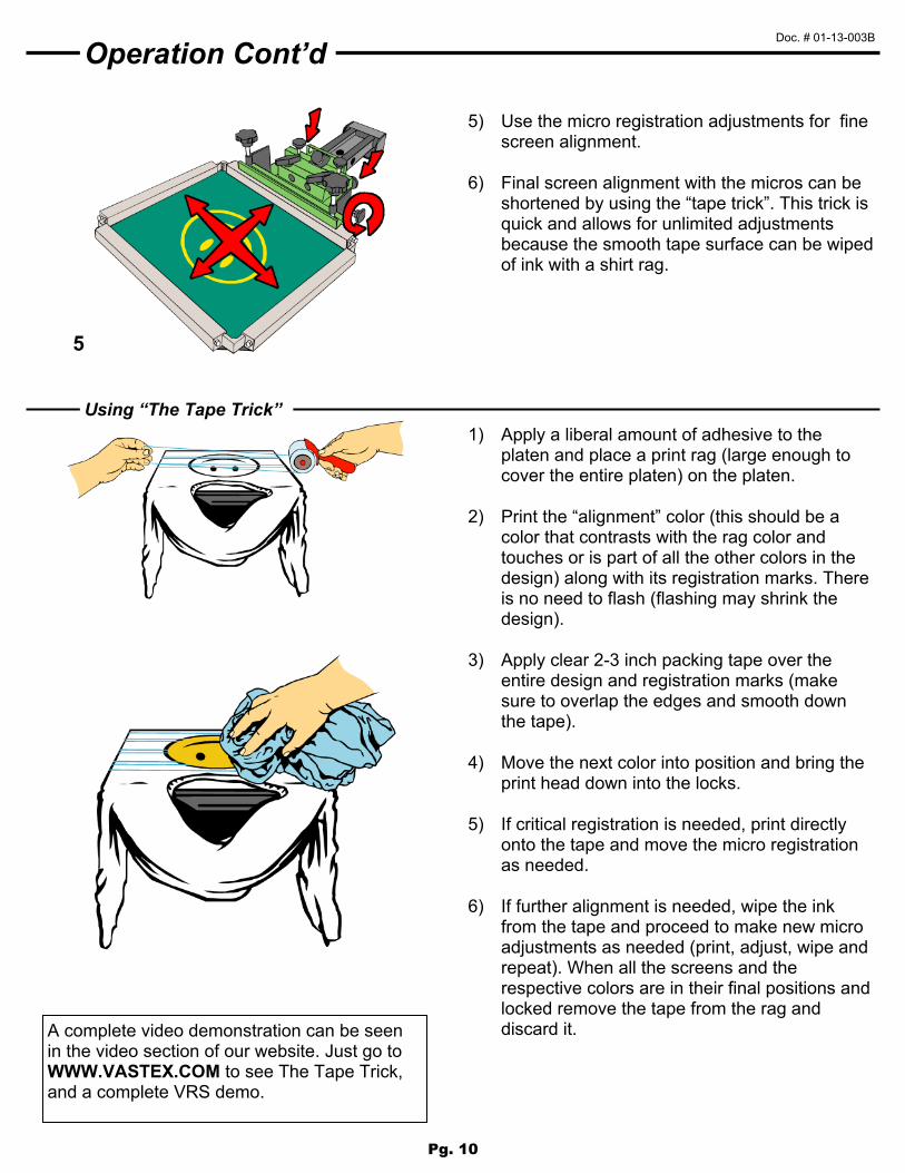
Using “The Tape Trick”
Operation Cont’d
1) Apply a liberal amount of adhesive to theplaten and place a print rag (large enough tocover the entire platen) on the platen.
2) Print the “alignment” color (this should be acolor that contrasts with the rag color andtouches or is part of all the other colors in thedesign) along with its registration marks. Thereis no need to flash (flashing may shrink thedesign).
3) Apply clear 2-3 inch packing tape over theentire design and registration marks (makesure to overlap the edges and smooth downthe tape).
4) Move the next color into position and bring theprint head down into the locks.
5) If critical registration is needed, print directlyonto the tape and move the micro registrationas needed.
6) If further alignment is needed, wipe the inkfrom the tape and proceed to make new microadjustments as needed (print, adjust, wipe andrepeat). When all the screens and therespective colors are in their final positions andlocked remove the tape from the rag anddiscard it.
5) Use the micro registration adjustments for finescreen alignment.
6) Final screen alignment with the micros can beshortened by using the “tape trick”. This trick isquick and allows for unlimited adjustmentsbecause the smooth tape surface can be wipedof ink with a shirt rag.
Pg. 10

Pg. 11

Pg. 12