Embed Size (px)
Citation preview
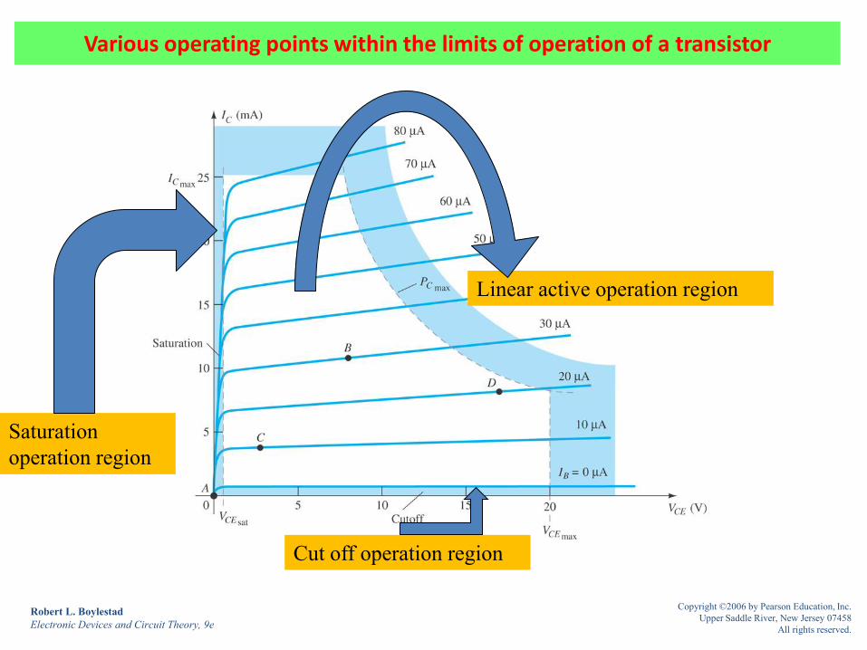
Various operating points within the limits of operation of a transistor
Robert L. Boylestad
Electronic Devices and Circuit Theory, 9e
Copyright ©2006 by Pearson Education, Inc.
Upper Saddle River, New Jersey 07458
All rights reserved.
Linear active operation region
Cut off operation region
Saturation
operation region

Fixed-bias circuit
Robert L. Boylestad
Electronic Devices and Circuit Theory, 9e
Copyright ©2006 by Pearson Education, Inc.
Upper Saddle River, New Jersey 07458
All rights reserved.

DC biasing
Robert L. Boylestad
Electronic Devices and Circuit Theory, 9e
Copyright ©2006 by Pearson Education, Inc.
Upper Saddle River, New Jersey 07458
All rights reserved.
GRAPHICAL
Given circuit
DC equivalent circuit
MATHMAICAL

DC equivalent circuit
Robert L. Boylestad
Electronic Devices and Circuit Theory, 9e
Copyright ©2006 by Pearson Education, Inc.
Upper Saddle River, New Jersey 07458
All rights reserved.

Base–emitter loop. ( input section loop)
Robert L. Boylestad
Electronic Devices and Circuit Theory, 9e
Copyright ©2006 by Pearson Education, Inc.
Upper Saddle River, New Jersey 07458
All rights reserved.

Collector–emitter loop. (output section loop)
Robert L. Boylestad
Electronic Devices and Circuit Theory, 9e
Copyright ©2006 by Pearson Education, Inc.
Upper Saddle River, New Jersey 07458
All rights reserved.

Measuring VCE and VC
Robert L. Boylestad
Electronic Devices and Circuit Theory, 9e
Copyright ©2006 by Pearson Education, Inc.
Upper Saddle River, New Jersey 07458
All rights reserved.

Example : find IBQ , ICQ , VCEQ , VB , VC , VBC
Robert L. Boylestad
Electronic Devices and Circuit Theory, 9e
Copyright ©2006 by Pearson Education, Inc.
Upper Saddle River, New Jersey 07458
All rights reserved.

Saturation regions: (a) actual; (b) approximate
Robert L. Boylestad
Electronic Devices and Circuit Theory, 9e
Copyright ©2006 by Pearson Education, Inc.
Upper Saddle River, New Jersey 07458
All rights reserved.

Determining ICsat
Robert L. Boylestad
Electronic Devices and Circuit Theory, 9e
Copyright ©2006 by Pearson Education, Inc.
Upper Saddle River, New Jersey 07458
All rights reserved.

Determining ICsat for the fixed-bias configuration
Robert L. Boylestad
Electronic Devices and Circuit Theory, 9e
Copyright ©2006 by Pearson Education, Inc.
Upper Saddle River, New Jersey 07458
All rights reserved.
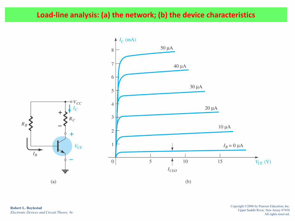
Load-line analysis: (a) the network; (b) the device characteristics
Robert L. Boylestad
Electronic Devices and Circuit Theory, 9e
Copyright ©2006 by Pearson Education, Inc.
Upper Saddle River, New Jersey 07458
All rights reserved.

Fixed-bias load line
Robert L. Boylestad
Electronic Devices and Circuit Theory, 9e
Copyright ©2006 by Pearson Education, Inc.
Upper Saddle River, New Jersey 07458
All rights reserved.

Movement of the Q-point with increasing level of IB
Robert L. Boylestad
Electronic Devices and Circuit Theory, 9e
Copyright ©2006 by Pearson Education, Inc.
Upper Saddle River, New Jersey 07458
All rights reserved.

Effect of an increasing level of RC on the load line and the Q-point
Robert L. Boylestad
Electronic Devices and Circuit Theory, 9e
Copyright ©2006 by Pearson Education, Inc.
Upper Saddle River, New Jersey 07458
All rights reserved.

Effect of lower values of VCC on the load line and the Q-point
Robert L. Boylestad
Electronic Devices and Circuit Theory, 9e
Copyright ©2006 by Pearson Education, Inc.
Upper Saddle River, New Jersey 07458
All rights reserved.

Example : find VCC , RC , RB for the fixed biasing configuration
Robert L. Boylestad
Electronic Devices and Circuit Theory, 9e
Copyright ©2006 by Pearson Education, Inc.
Upper Saddle River, New Jersey 07458
All rights reserved.

BJT bias circuit with emitter resistor
Robert L. Boylestad
Electronic Devices and Circuit Theory, 9e
Copyright ©2006 by Pearson Education, Inc.
Upper Saddle River, New Jersey 07458
All rights reserved.

Base–emitter loop. (input section loop)
Robert L. Boylestad
Electronic Devices and Circuit Theory, 9e
Copyright ©2006 by Pearson Education, Inc.
Upper Saddle River, New Jersey 07458
All rights reserved.

Network derived from Eq. (4.17). (input loop)
Robert L. Boylestad
Electronic Devices and Circuit Theory, 9e
Copyright ©2006 by Pearson Education, Inc.
Upper Saddle River, New Jersey 07458
All rights reserved.

Reflected impedance level of RE
Robert L. Boylestad
Electronic Devices and Circuit Theory, 9e
Copyright ©2006 by Pearson Education, Inc.
Upper Saddle River, New Jersey 07458
All rights reserved.

Collector–emitter loop. (output loop)
Robert L. Boylestad
Electronic Devices and Circuit Theory, 9e
Copyright ©2006 by Pearson Education, Inc.
Upper Saddle River, New Jersey 07458
All rights reserved.

Example
Robert L. Boylestad
Electronic Devices and Circuit Theory, 9e
Copyright ©2006 by Pearson Education, Inc.
Upper Saddle River, New Jersey 07458
All rights reserved.

Determining ICsat for the emitter-stabilized bias circuit
Robert L. Boylestad
Electronic Devices and Circuit Theory, 9e
Copyright ©2006 by Pearson Education, Inc.
Upper Saddle River, New Jersey 07458
All rights reserved.

Load line for the emitter-bias configuration
Robert L. Boylestad
Electronic Devices and Circuit Theory, 9e
Copyright ©2006 by Pearson Education, Inc.
Upper Saddle River, New Jersey 07458
All rights reserved.

Voltage-divider bias configuration
Robert L. Boylestad
Electronic Devices and Circuit Theory, 9e
Copyright ©2006 by Pearson Education, Inc.
Upper Saddle River, New Jersey 07458
All rights reserved.

Voltage-divider bias configuration
Robert L. Boylestad
Electronic Devices and Circuit Theory, 9e
Copyright ©2006 by Pearson Education, Inc.
Upper Saddle River, New Jersey 07458
All rights reserved.
Approximated solution
Exact solution

Defining the Q-point for the voltage-divider bias configuration
Robert L. Boylestad
Electronic Devices and Circuit Theory, 9e
Copyright ©2006 by Pearson Education, Inc.
Upper Saddle River, New Jersey 07458
All rights reserved.

Redrawing the input side of the network of Fig. 4.25
Robert L. Boylestad
Electronic Devices and Circuit Theory, 9e
Copyright ©2006 by Pearson Education, Inc.
Upper Saddle River, New Jersey 07458
All rights reserved.
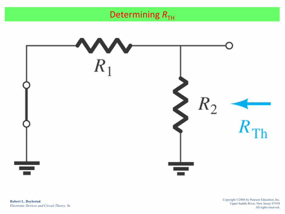
Determining RTH
Robert L. Boylestad
Electronic Devices and Circuit Theory, 9e
Copyright ©2006 by Pearson Education, Inc.
Upper Saddle River, New Jersey 07458
All rights reserved.

Determining ETH
Robert L. Boylestad
Electronic Devices and Circuit Theory, 9e
Copyright ©2006 by Pearson Education, Inc.
Upper Saddle River, New Jersey 07458
All rights reserved.

Inserting the Thévenin equivalent circuit
Robert L. Boylestad
Electronic Devices and Circuit Theory, 9e
Copyright ©2006 by Pearson Education, Inc.
Upper Saddle River, New Jersey 07458
All rights reserved.

Example
Robert L. Boylestad
Electronic Devices and Circuit Theory, 9e
Copyright ©2006 by Pearson Education, Inc.
Upper Saddle River, New Jersey 07458
All rights reserved.

Approximated method
Robert L. Boylestad
Electronic Devices and Circuit Theory, 9e
Copyright ©2006 by Pearson Education, Inc.
Upper Saddle River, New Jersey 07458
All rights reserved.

Voltage-divider configuration for Example 4.10
Robert L. Boylestad
Electronic Devices and Circuit Theory, 9e
Copyright ©2006 by Pearson Education, Inc.
Upper Saddle River, New Jersey 07458
All rights reserved.

DC bias circuit with voltage feedback
Robert L. Boylestad
Electronic Devices and Circuit Theory, 9e
Copyright ©2006 by Pearson Education, Inc.
Upper Saddle River, New Jersey 07458
All rights reserved.

Base–emitter loop for the network ( input loop)
Robert L. Boylestad
Electronic Devices and Circuit Theory, 9e
Copyright ©2006 by Pearson Education, Inc.
Upper Saddle River, New Jersey 07458
All rights reserved.

Collector–emitter loop for the network (output loop)
Robert L. Boylestad
Electronic Devices and Circuit Theory, 9e
Copyright ©2006 by Pearson Education, Inc.
Upper Saddle River, New Jersey 07458
All rights reserved.

Example
Robert L. Boylestad
Electronic Devices and Circuit Theory, 9e
Copyright ©2006 by Pearson Education, Inc.
Upper Saddle River, New Jersey 07458
All rights reserved.

Example
Robert L. Boylestad
Electronic Devices and Circuit Theory, 9e
Copyright ©2006 by Pearson Education, Inc.
Upper Saddle River, New Jersey 07458
All rights reserved.

Example : Collector feedback with RE = 0Ω
Robert L. Boylestad
Electronic Devices and Circuit Theory, 9e
Copyright ©2006 by Pearson Education, Inc.
Upper Saddle River, New Jersey 07458
All rights reserved.

Example
Robert L. Boylestad
Electronic Devices and Circuit Theory, 9e
Copyright ©2006 by Pearson Education, Inc.
Upper Saddle River, New Jersey 07458
All rights reserved.

Example : Common-collector (emitter-follower) configuration
Robert L. Boylestad
Electronic Devices and Circuit Theory, 9e
Copyright ©2006 by Pearson Education, Inc.
Upper Saddle River, New Jersey 07458
All rights reserved.

Common-base configuration
Robert L. Boylestad
Electronic Devices and Circuit Theory, 9e
Copyright ©2006 by Pearson Education, Inc.
Upper Saddle River, New Jersey 07458
All rights reserved.

Example
Robert L. Boylestad
Electronic Devices and Circuit Theory, 9e
Copyright ©2006 by Pearson Education, Inc.
Upper Saddle River, New Jersey 07458
All rights reserved.

Determining RTH
Robert L. Boylestad
Electronic Devices and Circuit Theory, 9e
Copyright ©2006 by Pearson Education, Inc.
Upper Saddle River, New Jersey 07458
All rights reserved.

Determining ETH
Robert L. Boylestad
Electronic Devices and Circuit Theory, 9e
Copyright ©2006 by Pearson Education, Inc.
Upper Saddle River, New Jersey 07458
All rights reserved.
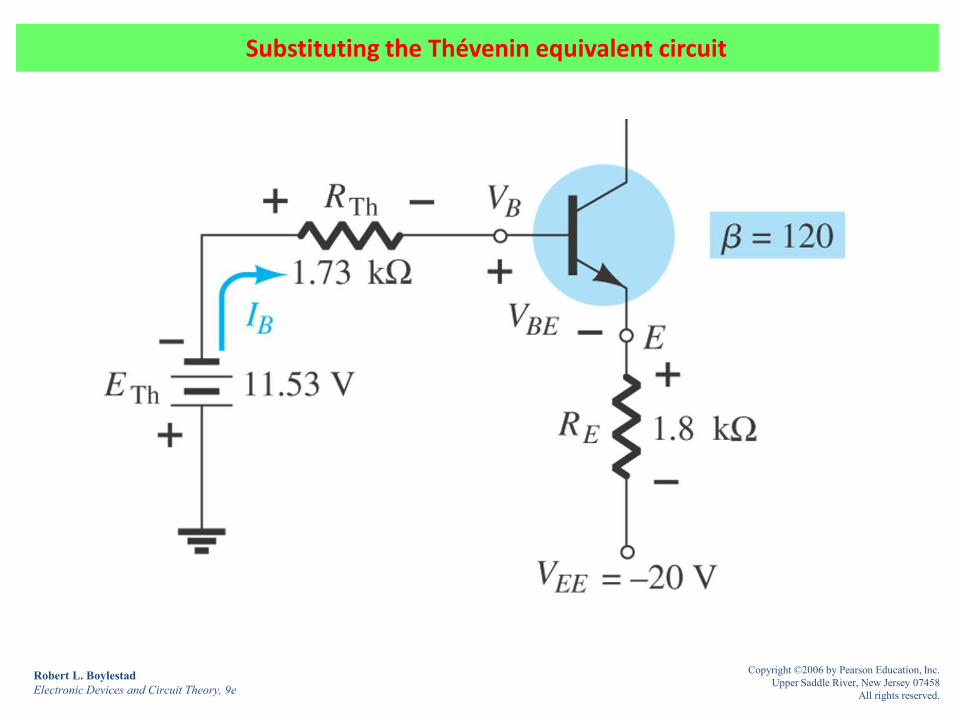
Substituting the Thévenin equivalent circuit
Robert L. Boylestad
Electronic Devices and Circuit Theory, 9e
Copyright ©2006 by Pearson Education, Inc.
Upper Saddle River, New Jersey 07458
All rights reserved.

Example : Design the circuit
Robert L. Boylestad
Electronic Devices and Circuit Theory, 9e
Copyright ©2006 by Pearson Education, Inc.
Upper Saddle River, New Jersey 07458
All rights reserved.

Example : Design the circuit
Robert L. Boylestad
Electronic Devices and Circuit Theory, 9e
Copyright ©2006 by Pearson Education, Inc.
Upper Saddle River, New Jersey 07458
All rights reserved.

Example : Design
Robert L. Boylestad
Electronic Devices and Circuit Theory, 9e
Copyright ©2006 by Pearson Education, Inc.
Upper Saddle River, New Jersey 07458
All rights reserved.

DESIGN : Emitter-stabilized bias circuit for design consideration
Robert L. Boylestad
Electronic Devices and Circuit Theory, 9e
Copyright ©2006 by Pearson Education, Inc.
Upper Saddle River, New Jersey 07458
All rights reserved.

DESIGN : Current-gain-stabilized circuit for design considerations
Robert L. Boylestad
Electronic Devices and Circuit Theory, 9e
Copyright ©2006 by Pearson Education, Inc.
Upper Saddle River, New Jersey 07458
All rights reserved.

Network for Example 4.25
Robert L. Boylestad
Electronic Devices and Circuit Theory, 9e
Copyright ©2006 by Pearson Education, Inc.
Upper Saddle River, New Jersey 07458
All rights reserved.

Fig. 4.63 Network for Example 4.26
Robert L. Boylestad
Electronic Devices and Circuit Theory, 9e
Copyright ©2006 by Pearson Education, Inc.
Upper Saddle River, New Jersey 07458
All rights reserved.

pnp transistor in an emitter-stabilized configuration
Robert L. Boylestad
Electronic Devices and Circuit Theory, 9e
Copyright ©2006 by Pearson Education, Inc.
Upper Saddle River, New Jersey 07458
All rights reserved.

Fig. 4.65 pnp transistor in a voltage-divider bias configuration
Robert L. Boylestad
Electronic Devices and Circuit Theory, 9e
Copyright ©2006 by Pearson Education, Inc.
Upper Saddle River, New Jersey 07458
All rights reserved.

Fig. 4.68 Equivalent circuit for the voltage-divider configuration
Robert L. Boylestad
Electronic Devices and Circuit Theory, 9e
Copyright ©2006 by Pearson Education, Inc.
Upper Saddle River, New Jersey 07458
All rights reserved.