Embed Size (px)
Citation preview

MORE ON WHAT IS CAVITATION?Jacques Chaurette p. eng.,
ww.lightmypump.com February 2003
Cavitation begins as the formation of vapor bubbles at the impeller eye due to low pressure. The bubbles form at the position of lowest pressure at the pump inlet (see Figure 1), which is just prior to the fluid being acted upon by the impeller vanes, they are then rapidly compressed. The compression of the vapor bubbles produces a small shock wave that impacts the impeller surface and pits away at the metal creating over time large eroded areas and subsequent failure. The sound of cavitation is very characteristic and resembles the sound of gravel in a concrete mixer. You can hear this sound by downloading the cavitation sound file in mp3 format from the lightmypump web site www.lightmypump.com, go to the DOWNLOADS page.
Figure 1 Pressure profile at the pump entrance.

More on what is cavitation…2
As you can see from Figure 1 the pressure available at the pump inlet, which is the pressure that we would measure if we put a gauge at that point, can be reasonably high but still drop considerably as it makes it way into the pump. The pressure may be lowered enough that the fluid will vaporize and will then produce cavitation.
The same effect can sometimes be seen in control valves because they have a similar pressure drop profile, if the pressure is insufficient at the control valve inlet cavitation will also occur.
Vapor pressure and cavitation
There are two ways to boil a liquid. One way is to increase the temperature while keeping the pressure constant until the temperature is high enough to produce vapor bubbles. In Figure 2 this is what happens if you take one point in the liquid phase and you move horizontally (that is at constant pressure) by increasing the temperature. Eventually you hit the vaporization line of the particular fluid and the fluid starts to boil or produce vapor bubbles. We do the same thing every day when we boil water in a pot.
The other way to boil a liquid is to lower the pressure. If you keep the temperature constant and lower the pressure the liquid will also boil. In Figure 2 this is what happens if you take one point in the liquid phase and you move vertically (that is at constant temperature) by decreasing the pressure. Again you hit the vaporization line of the particular fluid and the fluid starts to boil or produce vapor bubbles.
If the pot were covered and you had a source of vacuum (see Figure 3) by lowering the pressure in the pot you would be able to make the water boil at a lower temperature. When the pressure is 7.5 psia or (14.7 – 7.5 = 7.2) or 7.2 psi less than the atmospheric pressure the water will boil at a temperature of 180 F and when the pressure is 1.5 psia the water will boil at 120 F. This is what happens at the pump suction when the pressure is low enough to make the fluid boil or vaporize.
It is not unusual for industrial processes to operate at temperatures that are close or higher than 120 F. Therefore if the temperature is high and the pressure drops as the fluid enters the pump, it will be easier to produce cavitation because the pressure drop produced by the pump will have to be smaller to match a higher vapor pressure. If cavitation is occurring or suspected, two possible solutions are: to increase the pressure at the pump inlet or decrease the fluid temperature.
Figure 2 Vapor pressure vs. temperature.

More on what is cavitation…3
Figure 3 Making a liquid boil under low pressure.
The pressure at which the liquid vaporizes is known as the vapor pressure and is always specified for a given temperature. If the temperature changes, the vapor pressure changes.
HOW TO AVOID CAVITATION? CAVITATION CAN BE AVOIDED IF THE N.P.S.H. AVAILABLE IS LARGER THAN THE N.P.S.H. REQUIRED.
Net Positive Suction Head Available (N.P.S.H.A.)
The Net Positive Suction Head Available (N.P.S.H.A.) is the total energy per unit weight, or head, at the suction flange of the pump less the vapor pressure head of the fluid. This is the accepted definition that is published by the Hydraulic Institute’s Standards books (see the HI web site at www. pumps.org). The Hydraulic Institute is the organization that formulates and promotes the use of common standards used for the pump industry in North America. The term "Net" refers to the actual head at the pump suction flange, since some energy is lost in friction prior to the suction.
Why do we need to calculate the N.P.S.H.A.? This value is required to avoid cavitation. Cavitation will be avoided if the head at the suction is higher than the vapor pressure head of the fluid. In addition, the pump manufacturers require a minimum N.P.S.H. to guarantee proper operation of the pump at the values of total head and flow rate indicated on the pump`s characteristic curves. They call this the N.P.S.H.R., where “R” stands for required.
More on what is cavitation…4
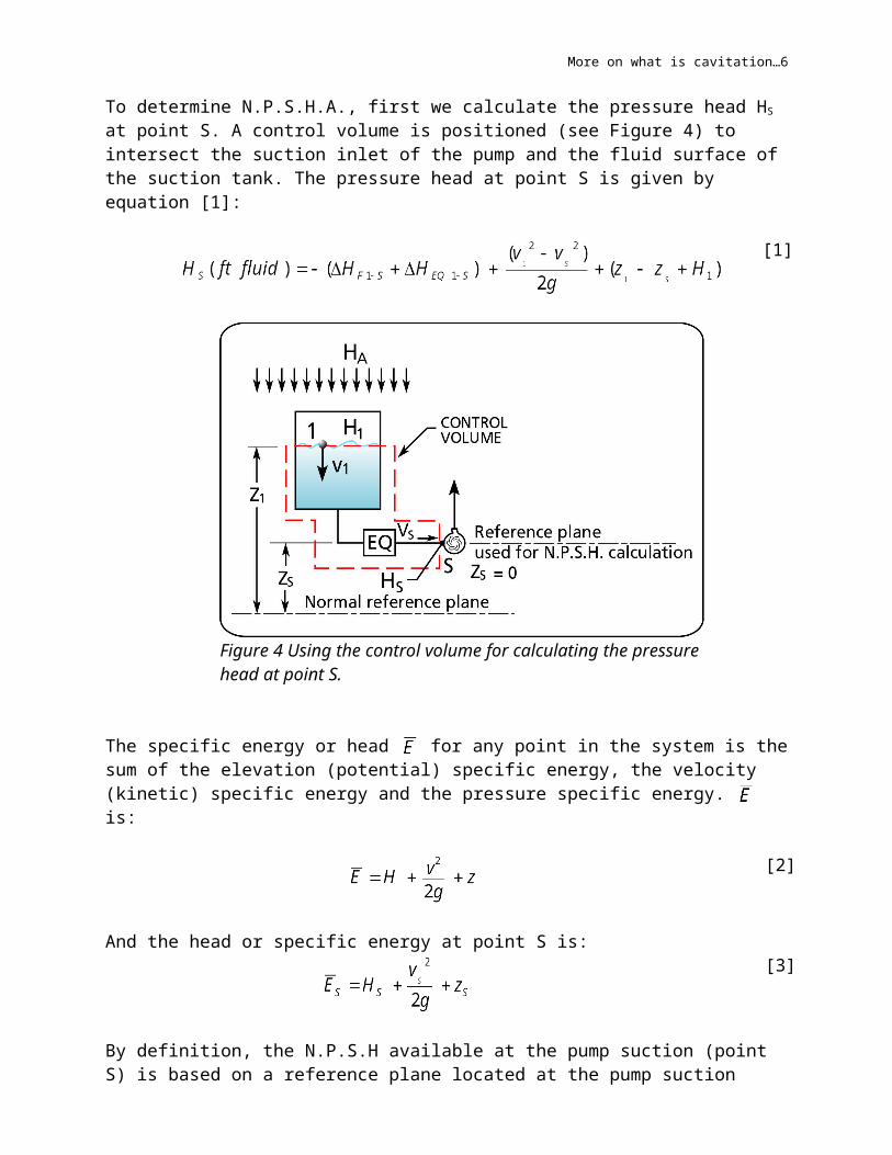
To determine N.P.S.H.A., first we calculate the pressure head HS at point S. A control volume is positioned (see Figure 4) to intersect the suction inlet of the pump and the fluid surface of the suction tank. The pressure head at point S is given by equation [1]:
[1]
Figure 4 Using the control volume for calculating the pressure head at point S.
The specific energy or head for any point in the system is the sum of the elevation (potential) specific energy, the velocity (kinetic) specific energy and the pressure specific energy. is:
[2]
And the head or specific energy at point S is:[3]
By definition, the N.P.S.H available at the pump suction (point S) is based on a reference plane located at the pump suction centerline (zS = 0 ). We can understand why since using any other reference will increase or decrease the specific energy level due to elevation at point S, which is obviously incorrect (see Figure 4).

More on what is cavitation…5
And since zS = 0 then:
[4]
The head is given in equation [4], the atmospheric pressure head (HA) is added to HS to convert from feet of fluid to feet of fluid absolute. Therefore equation [4] becomes:
[5]
The value of HS in equation [1] is substituted in equation [5] to give:
[6]
If the tank is not pressurized then H1 = 0.
In order for the liquid to stay in a fluid state and not vaporize, the head at the inlet of the pump must be above the vapor pressure head of the fluid:
where Hva is the vapor pressure head of the liquid. The Net Positive Suction Head Available (N.P.S.H.A.) is the difference between the head ( ) at the pump suction and the vapor pressure head (Hva).
[7]
By substituting the value of from equation [6] into equation [7] then:
[8]
where HA and Hva are in feet of fluid.
Vapor and atmospheric pressures are often given in pounds per square inch absolute (psia). The conversion of head in feet of fluid to pressure in psi is:
by substitution into equation [8]:
More on what is cavitation…6
[9]
The N.P.S.H. in equation [8] and [9] is in feet of fluid absolute and is a head term, head is independent of fluid density. Since the pump manufacturers use water as the fluid, the N.P.S.H. value they provide is in feet of water absolute.
The pump requires a minimum suction head in order to function properly and avoid cavitation. This is known as the N.P.S.H required which the pump manufacturer gives for a specific pump model, impeller diameter, speed and flow rate. In order to satisfy the pump manufacturer's requirements for proper operation the N.P.S.H available must be higher than the N.P.S.H required:
Figure 5 shows typical relative proportions of the terms in equation [8].
Figure 5 Relative sizes of N.P.S.H. components.

More on what is cavitation…7
Net Positive Suction Head Required (N.P.S.H.R.)
The N.P.S.H. required provides us with the level of head in terms of feet of water absolute required at the pump suction flange. When that level of head is insufficient the capacity and head of the pump will drop and cavitation will occur.
How do the pump manufacturers measure N.P.S.H. required?
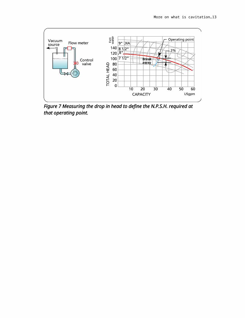
The pump manufacturers measure the N.P.S.H. required in a test rig similar to that shown in Figure 6. The system is run in a closed loop where flow, total head and power consumed are measured. In order to provide a low N.P.S.H., a vacuum pump is used to lower the pressure in the suction tank that will provide a low head at the pump suction. The pressure in the suction tank is lowered until a drop of 3% (see figure 7) of the total head is measured. When that occurs the N.P.S.H. is calculated and recorded as the N.P.S.H. required for that operating point. The experiment is repeated for many operating points. Heating coils are also used to increase the water temperature thereby increasing the vapor pressure and further lowering the N.P.S.H. as needed.
Figure 6 Test rig used to measure N.P.S.H. required(courtesy of the Hydraulic Institute www.pumps.org).

More on what is cavitation…8
Figure 7 Measuring the drop in head to define the N.P.S.H. required at that operating point.Figure 7 Measuring the drop in head to define the N.P.S.H. required at that operating point.Figure 7 Measuring the drop in head to define the N.P.S.H. required at that operating point.

More on what is cavitation…9
In the case where you have no data from the manufacturer for establishing the N.P.S.H.R., Figure 8 provides an estimate for N.P.S.H.R. for centrifugal pumps (source: Centrifugal Pump Design & Application by Val.S.Labanoff and Robert R Ross

More on what is cavitation…10
Guideline for the level of N.P.S.H. availableFigure 8 N.P.S.H.R. prediction based on the suction eye velocity.

More on what is cavitation…11
As stated, a total head drop of 3% is the criteria for setting the level of N.P.S.H. required. Since this results in a performance drop the user should ensure that there is a higher N.P.S.H. available. The recommendation that you will find in the literature is to have 5 ft of water absolute or a 15% margin above the N.P.S.H. required whichever is greatest.
How can the N.P.S.H. available be increased and cavitation avoided?
Table 1 gives the major components of N.P.S.H. available and how they affect the level of N.P.S.H. available.
The N.P.S.H. available depends on: Effect on N.P.S.H. available.1. The friction loss in the pump suction line. The higher the friction loss, the lower the
N.P.S.H. available.2. The height of the suction tank fluid surface with respect to the pump suction.
The lower the height of the fluid surface, the lower the N.P.S.H. available.
3. The pressure in the suction tank. This cannot be changed for atmospheric tanks. For tanks that are pressurized, the lower the pressure, the lower the N.P.S.H. available.
4. The atmospheric pressure. This cannot be changed and depends on the elevation above sea level. The lower the atmospheric pressure, the lower the N.P.S.H. available.
5. Fluid temperature. An increase in fluid temperature increases the vapor pressure of the fluid which decreases the N.P.S.H. available.
Table 1. How to affect the N.P.S.H. available.

More on what is cavitation…12
How can you measure N.P.S.H. available?
It is easier to measure N.P.S.H. available than to calculate it, here’s how it’s done.
By definition, the NPSH available is the specific energy or head at the pump suction in terms of feet of fluid absolute, minus the vapor pressure of the fluid. According to equation [4], the head at point S is:
[4]
The value of HS is :
[10]
Where the elevation difference zGS – zS compensates for the height of the pressure gauge above the pump centerline.
By substituting the value of HS from equation [10] into equation [4} we obtain:
[11]
Since N.P.S.H. is in feet of fluid absolute, the value of the atmospheric pressure head must be added to and the vapor pressure of the liquid (Hva) is subtracted to get the N.P.S.H. available.
[12]
Figure 9 Location of the pressure gauges to measure N.P.S.H. available.
More on what is cavitation…13
By substituting equation [11] into [12] we obtain:
[13]
Or if the atmospheric and vapor pressures are available in terms of psi, then:
[14]
What is the difference between the N.P.S.H.A. of equation [13] vs the N.P.S.H.A. of equation [8] which is restated here below:
[8]
Equation [8] corresponds to the NPSH available that is calculated according to the amount of specific energy or head available at the pump suction, which depends on the static head in the reservoir minus the friction head in the suction line. However equation [13] is the NPSH available based on a pressure measurement at the suction of the pump or point S. The static head less the friction head loss in the suction line generates the head available at point S; their contribution to pressure at point S is included in the pressure measurement.
Why is the velocity head at the pump suction required in equation [13], but not in equation [8]? In equation [8] the velocity energy was considered but cancels out during the development of the equation so that it does not appear in equation [8].

More on what is cavitation…14
Symbols
Variable nomenclature Imperial system(FPS units)
Metric system(SI units)
g acceleration due to gravity: 32.17 ft/s2
ft/s2 (feet/second squared)
m/s2
(meter/second squared)
specific energy or head ft (feet) m (meter)H head ft (feet) m (meter)HP Total Head ft (feet) m (meter)HEQ equipment head difference ft (feet) m (meter)HF friction head difference ft (feet) m (meter)p pressure psi (pound per square
inch)kPa (kiloPascal)
SG specific gravity; ratio of the fluid density to the density of water at standard conditions
non-dimensional
T temperature F (degrees Fahrenheit)
C (degrees Celsius)
v velocity ft/s (feet/second) m/s (meter/second)
z vertical position ft (feet) m (meter)


![DETAILED OBSERVATIONS ON A STARTING MECHANISM … · super-cavitation with clear cavity surface and cavity pressure near vapor one [14]. In the transition stage, namely from sub-](https://img.pdfslide.us/doc/110x75/5b4f640d7f8b9a346e8c3145/detailed-observations-on-a-starting-mechanism-super-cavitation-with-clear-cavity.jpg)