Embed Size (px)
Citation preview
PDMS ISODRAFT User Guide
Version 11.6SP1
pdms1160/ISODRAFT User Guide issue 080904 www.cadfamily.com EMail:[email protected]
The document is for study only,if tort to your rights,please inform us,we will delete

PLEASE NOTE:
AVEVA Solutions has a policy of continuing product development: therefore, the information contained in this document may be subject to change without notice. AVEVA SOLUTIONS MAKES NO WARRANTY OF ANY KIND WITH REGARD TO THIS DOCUMENT, INCLUDING BUT NOT LIMITED TO, THE IMPLIED WARRANTIES OF MERCHANTABILITY AND FITNESS FOR A PARTICULAR PURPOSE. While every effort has been made to verify the accuracy of this document, AVEVA Solutions shall not be liable for errors contained herein or direct, indirect, special, incidental or consequential damages in connection with the furnishing, performance or use of this material.
This manual provides documentation relating to products to which you may not have access or which may not be licensed to you. For further information on which Products are licensed to you please refer to your licence conditions.
© Copyright 1991 through 2005 AVEVA Solutions Limited
All rights reserved. No part of this document may be reproduced, stored in a retrieval system or transmitted, in any form or by any means, electronic, mechanical, photocopying, recording or otherwise, without prior written permission of AVEVA Solutions. The software programs described in this document are confidential information and proprietary products of AVEVA Solutions or its licensors.
For details of AVEVA's worldwide sales and support offices, see our website at http://www.aveva.com
AVEVA Solutions Ltd, High Cross, Madingley Road, Cambridge CB3 0HB, UK www.cadfamily.com EMail:[email protected]
The document is for study only,if tort to your rights,please inform us,we will delete
Contents
1 Introduction to this Guide ----------------------------------------------------------------1-1 1.1 Scope of this Guide ----------------------------------------------------------------------------------------------- 1-1 1.2 How to Use this Guide-------------------------------------------------------------------------------------------- 1-1 1.3 Training for ISODRAFT ------------------------------------------------------------------------------------------ 1-1 1.4 How this Manual is Organised---------------------------------------------------------------------------------- 1-2 1.5 Conventions Used in this Manual------------------------------------------------------------------------------ 1-3
1.5.1 GUI Terms and Conventions............................................................................................1-5
2 Using ISODRAFT-----------------------------------------------------------------------------2-1 2.1 Introduction to ISODRAFT--------------------------------------------------------------------------------------- 2-1
2.1.1 Types of Isometrics ..........................................................................................................2-1 2.2 Starting ISODRAFT ----------------------------------------------------------------------------------------------- 2-2 2.3 Using the ISODRAFT GUI--------------------------------------------------------------------------------------- 2-3
2.3.1 Selecting the Type of Isometric........................................................................................2-3 2.3.2 Selecting the Options File ................................................................................................2-3 2.3.3 Selecting the Elements.....................................................................................................2-4 2.3.4 Selecting the Output.........................................................................................................2-4 2.3.5 Detailing the Selected Elements ......................................................................................2-4 2.3.6 Example of Detailing the CE Using the GUI.....................................................................2-5 2.3.7 Creating and Modifying Options Files ..............................................................................2-5
2.4 Controlling ISODRAFT from the Command Line ---------------------------------------------------------- 2-5 2.4.1 Output Filename and Mode..............................................................................................2-6 2.4.2 The Message File.............................................................................................................2-8 2.4.3 Assembling a Detail List ...................................................................................................2-8 2.4.4 The Isometric Detailing Commands...............................................................................2-10 2.4.5 Example of Detailing Using ISODRAFT Commands .....................................................2-11 2.4.6 The Isometric Output Format .........................................................................................2-12
2.5 Querying ----------------------------------------------------------------------------------------------------------- 2-13 2.6 The Option Defaults--------------------------------------------------------------------------------------------- 2-14 2.7 MDB Mode -------------------------------------------------------------------------------------------------------- 2-14 2.8 Saving 2-15
2.8.1 Saving and Restoring the Current Display Status..........................................................2-15 2.8.2 Saving Work ...................................................................................................................2-15 2.8.3 Seeing Changes Made by Other Users .........................................................................2-16
2.9 General PDMS Facilities --------------------------------------------------------------------------------------- 2-16 2.9.1 Finding the Current User Status.....................................................................................2-16 2.9.2 Finding the Current System Status ................................................................................2-16 2.9.3 Listing Multiple-Database Information............................................................................2-16
2.10 Summary of Commands --------------------------------------------------------------------------------------- 2-17
VANTAGE PDMS ISODRAFT contents-i User Guide Version 11.6SP1 www.cadfamily.com EMail:[email protected]
The document is for study only,if tort to your rights,please inform us,we will delete
Contents
3 Cataloguing Requirements -------------------------------------------------------------- 3-1 3.1 Component Descriptions ---------------------------------------------------------------------------------------- 3-1 3.2 Symbol Keys-------------------------------------------------------------------------------------------------------- 3-3 3.3 Component End Conditions Defined By P-Points --------------------------------------------------------- 3-4 3.4 Alternative Item Codes------------------------------------------------------------------------------------------- 3-5 3.5 The SHOP Flag ---------------------------------------------------------------------------------------------------- 3-5
3.5.1 Tube SHOP Flag ............................................................................................................. 3-6
4 Bolting------------------------------------------------------------------------------------------ 4-1 4.1 How Bolts are Stored in the Catalogue ---------------------------------------------------------------------- 4-1 4.2 Bolt Sets (BTSE) -------------------------------------------------------------------------------------------------- 4-1
4.2.1 The Number Attribute (NUMB) ........................................................................................ 4-2 4.2.2 The Bolt Length Attribute (BTHK).................................................................................... 4-3
4.3 Bolt Tables ---------------------------------------------------------------------------------------------------------- 4-3 4.4 Bolt Specifications------------------------------------------------------------------------------------------------- 4-4
4.4.1 Bolt Selection from Specification ..................................................................................... 4-4 4.4.2 Bolts SHOP Flag.............................................................................................................. 4-5 4.4.3 Additional Bolting Items ................................................................................................... 4-6 4.4.4 Selecting Bolts with Temperature or Pressure ................................................................ 4-7 4.4.5 How Bolts are Selected from the Specification ............................................................... 4-7
4.5 Bolt Length Calculation ------------------------------------------------------------------------------------------ 4-8 4.5.1 Bolt Length Calculation for Standard Flange-Gasket-Flange.......................................... 4-8 4.5.2 Bolt Length Calculation for General Wafer Components ................................................ 4-9 4.5.3 Bolt Length Calculation for Components with Mixed Bolt Needs .................................... 4-9 4.5.4 Bolt Length Calculation at Nozzles................................................................................ 4-10 4.5.5 Additional Bolting Items in Bolt Length Calculations ..................................................... 4-10
4.6 Part Numbers and Tags ----------------------------------------------------------------------------------------4-11 4.7 Example Wafer Lug Valve -------------------------------------------------------------------------------------4-11 4.8 Administrative and Geographical Use of Selectors ------------------------------------------------------4-18 4.9 Alternative Item codes for Bolts-------------------------------------------------------------------------------4-18 4.10 Producing a Bolting Report ------------------------------------------------------------------------------------4-19 4.11 Summary of Commands----------------------------------------------------------------------------------------4-20
5 Design Requirements --------------------------------------------------------------------- 5-1 5.1 Using the SPOOLER Module ---------------------------------------------------------------------------------- 5-1
5.1.1 Numbering in Spool Drawing Isometrics ......................................................................... 5-2 5.2 Attachment Point Elements ------------------------------------------------------------------------------------- 5-2 5.3 Reference Dimensions------------------------------------------------------------------------------------------- 5-5
5.3.1 Setting up a Reference Datum ........................................................................................ 5-5 5.3.2 Setting up a Reference Dimension.................................................................................. 5-9 5.3.3 Errors ............................................................................................................................. 5-10
5.4 Additional Items for Material Take-off -----------------------------------------------------------------------5-11 5.5 Data Consistency Checking -----------------------------------------------------------------------------------5-11 5.6 Summary of Commands----------------------------------------------------------------------------------------5-11
contents-ii VANTAGE PDMS ISODRAFT User Guide Version 11.6SP1 www.cadfamily.com EMail:[email protected]
The document is for study only,if tort to your rights,please inform us,we will delete
Contents
6 Piping Components in ISODRAFT -----------------------------------------------------6-1 6.1 In-line Components, Including Straight-through Valves -------------------------------------------------- 6-1 6.2 Angled, 3-Way, and 4-Way Valves ---------------------------------------------------------------------------- 6-3 6.3 Flanges 6-3
6.3.1 Pairs of Flanges ...............................................................................................................6-4 6.3.2 Reducing Flanges ............................................................................................................6-5
6.4 Wafer Fittings ------------------------------------------------------------------------------------------------------- 6-5 6.5 Tees and Crosses ------------------------------------------------------------------------------------------------- 6-6
6.5.1 Crosses ............................................................................................................................6-7 6.6 Reducers------------------------------------------------------------------------------------------------------------- 6-8
6.6.1 Reducers With a Branch Connection...............................................................................6-8 6.7 Elbows and Bends------------------------------------------------------------------------------------------------- 6-9 6.8 Pipe Ends and their Connections ---------------------------------------------------------------------------- 6-10
6.8.1 Connection To Equipment Nozzle..................................................................................6-12 6.8.2 Continuation on Another Drawing ..................................................................................6-12 6.8.3 Special Pipe End Conditions..........................................................................................6-13 6.8.4 Open and Closed Ends ..................................................................................................6-13
6.9 Field-fit Welds and Loose Flanges -------------------------------------------------------------------------- 6-14 6.10 Identifying Pipeline Specification Changes---------------------------------------------------------------- 6-15 6.11 Fixed Length Piping --------------------------------------------------------------------------------------------- 6-16
6.11.1 Fixed Length Piping In Isometric Drawings....................................................................6-16 6.11.2 Fixed Length Piping In Material Lists .............................................................................6-16
6.12 Summary of Commands --------------------------------------------------------------------------------------- 6-17
7 Customising the Drawing Sheet --------------------------------------------------------7-1 7.1 Isometric Types ---------------------------------------------------------------------------------------------------- 7-1 7.2 Units 7-1 7.3 Sheet Size ----------------------------------------------------------------------------------------------------------- 7-2
7.3.1 The Designed Drawing Sheet Size ..................................................................................7-2 7.3.2 The Plotted Drawing Sheet Size ......................................................................................7-2 7.3.3 Margins On Drawing Sheets ............................................................................................7-2 7.3.4 Blank Areas on the Drawing Sheet and Material list........................................................7-3
7.4 Using a Plot File as a Backdrop-------------------------------------------------------------------------------- 7-3 7.5 Arranging Multiple Plots on the Paper ------------------------------------------------------------------------ 7-3 7.6 Dynamic Detail Areas on the Drawing Sheet --------------------------------------------------------------- 7-3
7.6.1 Positioning the Detail Plots...............................................................................................7-4 7.7 The Drawing Frame ----------------------------------------------------------------------------------------------- 7-5 7.8 Sheet Cutting Marks ---------------------------------------------------------------------------------------------- 7-5 7.9 Line Summary Box ------------------------------------------------------------------------------------------------ 7-5 7.10 The Title Block------------------------------------------------------------------------------------------------------ 7-6
7.10.1 Additional Title Block Text ................................................................................................7-6 7.10.2 Suppressing Title Block Text............................................................................................7-6 7.10.3 Drawing Issue Numbering................................................................................................7-6 7.10.4 Project Numbers on Drawings .........................................................................................7-7 7.10.5 The Date Format ..............................................................................................................7-7
7.11 Alternative Text----------------------------------------------------------------------------------------------------- 7-7 7.12 User-Positioned Text --------------------------------------------------------------------------------------------- 7-7
VANTAGE PDMS ISODRAFT contents-iii User Guide Version 11.6SP1 www.cadfamily.com EMail:[email protected]
The document is for study only,if tort to your rights,please inform us,we will delete
Contents
7.12.1 User-Defined Tables........................................................................................................ 7-8 7.13 Summary of Commands----------------------------------------------------------------------------------------- 7-9
8 The Material List and Other Reports ------------------------------------------------- 8-1 8.1 Part Numbers------------------------------------------------------------------------------------------------------- 8-2 8.2 Changing the Text in Material List Descriptions ----------------------------------------------------------- 8-3 8.3 Excluding items from the Material List Descriptions ------------------------------------------------------ 8-3 8.4 Item Codes---------------------------------------------------------------------------------------------------------- 8-4
8.4.1 Specification Names in Item Codes................................................................................. 8-4 8.4.2 Using Names As Item Codes .......................................................................................... 8-4 8.4.3 Item Code Suffixes .......................................................................................................... 8-5
8.5 Cut Pipe Lengths -------------------------------------------------------------------------------------------------- 8-5 8.6 Filing Material List Data for Printing--------------------------------------------------------------------------- 8-6
8.6.1 Filing the Full Material List ............................................................................................... 8-6 8.6.2 Filing a Pipe Support Schedule ....................................................................................... 8-6 8.6.3 Pipe and Insulation Summary Files ................................................................................. 8-6 8.6.4 Cut Pipe Report Generation ............................................................................................ 8-7 8.6.5 Pipe Wastage Allowance................................................................................................. 8-7 8.6.6 Field-Fit Weld and Loose Flange Allowance ................................................................... 8-7
8.7 Bolting Information ------------------------------------------------------------------------------------------------ 8-7 8.8 Material Lists for Split Pipelines-------------------------------------------------------------------------------- 8-8 8.9 Summary of Commands----------------------------------------------------------------------------------------- 8-8
9 The Isometric Drawing -------------------------------------------------------------------- 9-1 9.1 Setting the Detail and Revision Flags ------------------------------------------------------------------------ 9-1 9.2 View Direction------------------------------------------------------------------------------------------------------ 9-1 9.3 Origins of Coordinate Axes ------------------------------------------------------------------------------------- 9-1
9.3.1 Elevations ........................................................................................................................ 9-3 9.4 Improving Legibility of the Isometric -------------------------------------------------------------------------- 9-3
9.4.1 Message Layout .............................................................................................................. 9-3 9.5 Splitting Long Pipelines ------------------------------------------------------------------------------------------ 9-4
9.5.1 Specifying Split Points ..................................................................................................... 9-4 9.5.2 Repeatability .................................................................................................................... 9-5
9.6 Dimensioning------------------------------------------------------------------------------------------------------- 9-6 9.6.1 Support/Hanger Dimensions ........................................................................................... 9-8 9.6.2 Bend Radii ....................................................................................................................... 9-8 9.6.3 Dimensional Units on Isometrics ..................................................................................... 9-9 9.6.4 Rounding and Truncation of Dimensions ........................................................................ 9-9 9.6.5 Positions of Dimensioning Lines.................................................................................... 9-10 9.6.6 Reference Dimensions .................................................................................................. 9-10
9.7 Support Attachment Point Names----------------------------------------------------------------------------9-10 9.8 Tolerances In Isometric Plotting ------------------------------------------------------------------------------9-11 9.9 Flow Arrows -------------------------------------------------------------------------------------------------------9-11 9.10 Plotted Leg Length -----------------------------------------------------------------------------------------------9-11 9.11 Skewed and Falling Pipelines ---------------------------------------------------------------------------------9-11
9.11.1 Skewed Lines ................................................................................................................ 9-11 9.11.2 Falling Lines................................................................................................................... 9-12 9.11.3 Skewed and Falling Lines.............................................................................................. 9-12
contents-iv VANTAGE PDMS ISODRAFT User Guide Version 11.6SP1 www.cadfamily.com EMail:[email protected]
The document is for study only,if tort to your rights,please inform us,we will delete
Contents
9.11.4 Zero-length Bends at Tees and OLETs .........................................................................9-13 9.12 Insulation and Tracing ------------------------------------------------------------------------------------------ 9-14 9.13 Marking Specification Changes ------------------------------------------------------------------------------ 9-15 9.14 Plotting Complete System Isometrics----------------------------------------------------------------------- 9-16
9.14.1 System Isometrics ..........................................................................................................9-16 9.14.2 Equipment Trims for Material Take Off ..........................................................................9-16
9.15 Welds 9-17 9.15.1 Weld Display ..................................................................................................................9-17 9.15.2 Weld Numbering.............................................................................................................9-17 9.15.3 Weld Identification ..........................................................................................................9-18
9.16 Item Codes and Name Tags on Isometrics --------------------------------------------------------------- 9-18 9.16.1 Item Codes .....................................................................................................................9-18 9.16.2 Name Tags.....................................................................................................................9-18 9.16.3 User-defined Tag Boxes ................................................................................................9-18
9.17 Pipe Ends and Connecting Nozzles------------------------------------------------------------------------- 9-19 9.17.1 Suppression of End Coordinates ...................................................................................9-19 9.17.2 Nozzle Continuation Symbols ........................................................................................9-19 9.17.3 Continuation Notes.........................................................................................................9-19
9.18 Summary of Commands --------------------------------------------------------------------------------------- 9-20
10 Drawing Change Highlighting ---------------------------------------------------------10-1 10.1 Highlighting-------------------------------------------------------------------------------------------------------- 10-1 10.2 The Comparison Date ------------------------------------------------------------------------------------------ 10-2 10.3 Summary of Commands --------------------------------------------------------------------------------------- 10-3
11 Symbol Keys --------------------------------------------------------------------------------11-1 11.1 The Basic Principles -------------------------------------------------------------------------------------------- 11-1 11.2 Symbol Attributes ------------------------------------------------------------------------------------------------ 11-2 11.3 Spindle SKEYS--------------------------------------------------------------------------------------------------- 11-3 11.4 Defining a New Hanger ---------------------------------------------------------------------------------------- 11-4 11.5 Pipe Components with More Than Four Connections -------------------------------------------------- 11-6 11.6 Offset Fittings ----------------------------------------------------------------------------------------------------- 11-8 11.7 Angled Fittings---------------------------------------------------------------------------------------------------- 11-9 11.8 Universal SKEYs------------------------------------------------------------------------------------------------11-11
11.8.1 End Connections ..........................................................................................................11-12 11.8.2 Tapping Syntax ............................................................................................................11-12 11.8.3 Connection Labelling....................................................................................................11-12
12 The ISODRAFT Transfer File-----------------------------------------------------------12-1 12.1 Preprocessing and Postprocessing Commands --------------------------------------------------------- 12-1 12.2 Summary of Commands --------------------------------------------------------------------------------------- 12-2
Index
VANTAGE PDMS ISODRAFT contents-v User Guide Version 11.6SP1 www.cadfamily.com EMail:[email protected]
The document is for study only,if tort to your rights,please inform us,we will delete

Contents
contents-vi VANTAGE PDMS ISODRAFT User Guide Version 11.6SP1 www.cadfamily.com EMail:[email protected]
The document is for study only,if tort to your rights,please inform us,we will delete
1 Introduction to this Guide
1.1 Scope of this Guide
This guide introduces PDMS ISODRAFT, AVEVA Solution Ltd’s isometric plotting facility. It explains the main concepts underlying ISODRAFT and describes how to tailor the options to your own standards. The on-line help, built into the program’s Graphical User Interface (GUI), describes how to carry out basic plotting operations and set up control files. Note: This guide does not give step-by-step instructions on how to
operate ISODRAFT from the command line, as this information is included in the VANTAGE PDMS ISODRAFT Reference Manual.
1.2 How to Use this Guide
There are two types of ISODRAFT user: • Users, who need to create isometrics using pre-defined option files.
New users will probably want to look first at Chapter 2, Using ISODRAFT, which describes how to produce isometrics from the command line and how to use the GUI. You may also find it helpful to read Chapter 6, Piping Components in ISODRAFT, which describes how piping components are usually plotted and annotated.
• System Administrators, who need to set up their own option files. You can create new files or modify existing ones. You must be a member of the ISOADMIN team to see the forms you want.
This guide describes how you can set-up the option files. But, you will probably make most use of the Command Reference chapter in the VANTAGE PDMS ISODRAFT Reference Manual.
1.3 Training for ISODRAFT
New users of ISODRAFT, who will be responsible for setting company standards for isometric production, should attend an ‘Isometric Drawing Production training course’, which covers the relationship between the
VANTAGE PDMS ISODRAFT 1-1 User Guide Version 11.6SP1 www.cadfamily.com EMail:[email protected]
The document is for study only,if tort to your rights,please inform us,we will delete

Introduction to this Guide
Catalogue database and ISODRAFT as well as ISODRAFT itself. You should have already attended a ‘PDMS Basic Training Course’ and the ‘PDMS Catalogues and Specifications Course’.
1.4 How this Manual is Organised
The paragraphs below give you a brief description of the contents of each chapter of this manual: Chapter 2 - Using ISODRAFT This chapter provides an introduction to ISODRAFT and explains how to produce isometrics in the default format. Chapter 3 - Cataloguing Requirements This chapter gives a brief description of how the Catalogue database (except Bolt Tables) is structured; in particular, the parts which are essential for using ISODRAFT. You may need to refer to the VANTAGE PDMS PARAGON Reference Manual for further details. Chapter 4 - Bolting Describes Bolt tables and how bolting requirements are calculated. Chapter 5 - Design Requirements Describes how piping components should be designed so that ISODRAFT can process the pipes correctly; in particular, how split points in pipelines are stored in the Design database. You may also need to refer to the VANTAGE PDMS DESIGN Reference Manual. Chapter 6 - Piping Components in ISODRAFT Describes how piping components are drawn on isometrics. Chapter 7 - Customising the Drawing Sheet Gives an overview of the commands used to customise the drawing sheet. Chapter 8 - The Material List and Other Reports Gives an overview of the commands used to customise the material list, and explains how to produce other reports. Chapter 9 - The Isometric Drawing Gives an overview of the commands used to customise the isometric drawing area. Chapter 10 - Drawing Change Highlighting Gives an overview of the process of marking changes made to drawings. Chapter 11 – Symbol Keys Describes how to modify the symbols (SKEYs) used to show piping components on isometrics, and how to create new ones.
1-2 VANTAGE PDMS ISODRAFT User Guide Version 11.6SP1 www.cadfamily.com EMail:[email protected]
The document is for study only,if tort to your rights,please inform us,we will delete
Introduction to this Guide
Chapter 12 - The ISODRAFT Transfer File Describes the ISODRAFT-ISODRAW transfer file. This information may be required by advanced users
1.5 Conventions Used in this Manual
Commands shown in a combination of uppercase and lowercase letters can be abbreviated: the capital letters of the command indicate the minimum abbreviation. Note: This convention does not mean that you have to type the second
part of the command in lowercase letters. You can enter commands in any combination of uppercase and lowercase letters.
For example, you can enter the command: CHeck in any of the following forms: CH CHE CHEC CHECK
You cannot abbreviate commands shown wholly in uppercase letters.
VANTAGE PDMS ISODRAFT 1-3 User Guide Version 11.6SP1 www.cadfamily.com EMail:[email protected]
The document is for study only,if tort to your rights,please inform us,we will delete
Introduction to this Guide
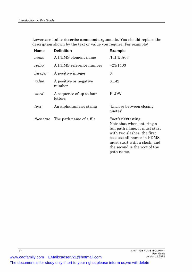
Lowercase italics describe command arguments. You should replace the description shown by the text or value you require. For example: Name Definition Example name A PDMS element name /PIPE-A63
refno A PDMS reference number =23/1403
integer A positive integer 3
value A positive or negative number
3.142
word A sequence of up to four letters
FLOW
text An alphanumeric string ’Enclose between closing quotes’
filename The path name of a file //net/sg99/testing. Note that when entering a full path name, it must start with two slashes: the first because all names in PDMS must start with a slash, and the second is the root of the path name.
1-4 VANTAGE PDMS ISODRAFT User Guide Version 11.6SP1 www.cadfamily.com EMail:[email protected]
The document is for study only,if tort to your rights,please inform us,we will delete

Introduction to this Guide
1.5.1 GUI Terms and Conventions
The following terms and conventions are used to describe what action to carry out in the GUI.
Term Description
Click Place the mouse cursor over the specified point, then quickly press and release the designated mouse button. If no button is specified always use the left-hand mouse button.
Double-click Quickly click the left-hand mouse button two times over the designated object.
Pick Click on the desired element in the 3D View window, to select it.
Drag Place the mouse cursor over the specified point on the screen; then press and hold the designated mouse button move the mouse cursor to the required point. When the mouse cursor is over the required point, release the button.
Enter Type text into the specified dialogue box and the press the Enter (or Return key).
VANTAGE PDMS ISODRAFT 1-5 User Guide Version 11.6SP1 www.cadfamily.com EMail:[email protected]
The document is for study only,if tort to your rights,please inform us,we will delete

Introduction to this Guide
1-6 VANTAGE PDMS ISODRAFT User Guide Version 11.6SP1 www.cadfamily.com EMail:[email protected]
The document is for study only,if tort to your rights,please inform us,we will delete
2 Using ISODRAFT
This chapter provides an introduction to ISODRAFT and describes how to use ISODRAFT to create an isometric drawing; by using either the GUI or by entering commands directly into the command line. The steps for processing isometric plot files using the GUI and Command Line are illustrated by examples in Sections 2.3.6 and 2.4.5, respectively.
2.1 Introduction to ISODRAFT
ISODRAFT can be used to produce isometric plot files of pipes and networks, from either the Design or Fabrication databases, to your own required standards. Normally, you will use these drawings for pipe work fabrication, but you can also use them during on-site erection. You can produce standard isometrics for zone, pipe, branch or spool drawing elements or for a mixture of these elements. In addition, system isometrics, showing a complete piping network, and equipment trim isometrics can be produced. Note: Mixed isometrics, containing elements from the Design and
Fabrication databases, cannot be produced. ISODRAFT produces your isometric drawings automatically, including any associated material lists you request. These material lists can specify: piping components; bolt requirements; pipe cutting lengths; etc. ISODRAFT uses the information in the project’s Design, Catalogue and Fabrication databases to produce the required lists. The isometrics produced can be fully dimensioned and annotated to ensure that you find them easy to use and unambiguous.
2.1.1 Types of Isometrics
You can include the following types of isometric in an ISODRAFT drawing: • Combined erection and fabrication isometric (standard) • Fabrication-only isometric (for shop floor use) • Erection-only isometric (for field use) • Spool drawing isometric
VANTAGE PDMS ISODRAFT 2-1 User Guide Version 11.6SP1 www.cadfamily.com EMail:[email protected]
The document is for study only,if tort to your rights,please inform us,we will delete
Using ISODRAFT
Each isometric type has its own forms of dimensioning annotation and material list. You can also control: • Complexity (drawing level density) of the isometric • View direction • Layout and units of dimensions • Annotation of the components shown on the isometric (type, part
number, specification, etc.) • Welding information • Insulation and tracing information • Material list position (either on the drawing sheet or separately) • Material list format • Symbols used to represent different types of piping components • Drawing sheet size • Drawing sheet annotation (title block text, company logo etc.) • Scaling of the isometric within the sheet (window size) • Text size All these drawing options have default settings so that you can begin creating drawings quickly. Normally ISODRAFT will be set up to use macros, to produce the isometrics for each project. See the VANTAGE Plant Design Software Customisation Guide for information about using macros in PDMS.
2.2 Starting ISODRAFT
You can start ISODRAFT either by starting PDMS in your usual way and selecting the ISODRAFT module, or by switching to the Isometric Generator (ISODRAFT) module from another module within PDMS. When ISODRAFT starts, the Application Window and Members list are displayed. If you wish to control ISODRAFT from the command line, you can display the Isodraft Command Input & Output form by selecting Display>Command Line from the main menu bar.
2-2 VANTAGE PDMS ISODRAFT User Guide Version 11.6SP1 www.cadfamily.com EMail:[email protected]
The document is for study only,if tort to your rights,please inform us,we will delete

Using ISODRAFT
2.3 Using the ISODRAFT GUI
ISODRAFT can be completely controlled from the application’s Graphical User Interface (GUI). The information displayed on the isometrics is controlled by Options files, allowing you to produce drawings to your own standards. Some option files are supplied with the product: these can be modified, or new option files created, to suit your company standards and projects. The basic procedure for producing an isometric using the GUI is: 1. Select the type of isometric you wish to produce (Standard or
System/Trim). 2. Select the options file you wish to use . 3. Select the element you wish to process, from the members list, or
assemble a detail list containing the elements. 4. Select the type of output required. 5. Plot the elements. These steps are explained in the following sections.
2.3.1 Selecting the Type of Isometric
To produce a Standard isometric, select Isometrics>Standard from the main menu bar. The Standard Isometric form is displayed.
2.3.2 Selecting the Options File
Options files can be created in three areas: Project, Company or Local. The files are accessed by selecting the required area from the Options drop-down list on the Standard Isometrics form. The names of the files in the area are displayed in the options scrollable list: • The Project standards: the files containing standard settings for the
(PDMS) project that you are in. There are some example files supplied with ISODRAFT.
• The Company standards: the files containing standard settings for your company. Two metric sample files (BASIC.MET and ADVANCED.MET) and two imperial sample files (BASIC.IMP and ADVANCED.IMP) are supplied with ISODRAFT.
• Local lists the contents of the current directory. Click on the options file you wish to use, to select it.
VANTAGE PDMS ISODRAFT 2-3 User Guide Version 11.6SP1 www.cadfamily.com EMail:[email protected]
The document is for study only,if tort to your rights,please inform us,we will delete
Using ISODRAFT
2.3.3 Selecting the Elements
You can elect to process either the Current Element and its members, or the contents of the Detail List, by selecting Current Element or Detail List from the Detail drop-down list on the Standard Isometrics form. If you select Current Element, you must select the CE in the Isodraft Members list. If the CE is a Zone, Group or ISOREG, the owned (or grouped) Pipes or Spool Drawings are processed. Assembling a ‘Detail List’ allows you to produce isometrics for several elements, which need not be in the same area of the database (or even in the same database), in one operation. To display the Isometric Detail List form, select Detail list from the Detail drop-down list. Note: This replaces the normal Isodraft Members list. The Isometric Detail List form contains two scrollable windows: one lists the Members in the selected database, in the same way as the Isodraft Members list; the other lists elements added to the Detail List. To add an element to the Detail List, select it in the Members List and click the Add button. Only Zones, Groups, Pipes, Branches, ISOREGs or Spool Drawings can be added. If the element is a Zone, Group or ISOREG, the owned (or grouped) Pipes or Spool Drawings are added rather than the element itself.
2.3.4 Selecting the Output
You can specify that an Isometric, Transfer file, Batch macro or Bolt report is produced. Select the required option from the Produce drop-down list on the Standard Isometrics form.
2.3.5 Detailing the Selected Elements
To detail the selected element(s), click the Apply button. A PDMS plot file for the isometric will be created in the directory specified in the options file. A material list file will also be created if material list production is switched on in the options file. When detailing is complete, the display will change to show the isometric displayed in the Display Isometric window. Two other forms, Isodraft Message and Display List, are also displayed.
2-4 VANTAGE PDMS ISODRAFT User Guide Version 11.6SP1 www.cadfamily.com EMail:[email protected]
The document is for study only,if tort to your rights,please inform us,we will delete
Using ISODRAFT
2.3.6 Example of Detailing the CE Using the GUI
The most basic method of using ISODRAFT is to detail the current element using one of the sets of options provided with the software. To detail an element: 1. Navigate to a pipe in the Design database, or a spool drawing in the
Fabrication database, in the Isodraft Members List. 2. Select Isometrics>Standard from the main menu bar. This displays
the Standard Isometric form, with the current element shown at the top.
Note: The element named next to the CE button will be detailed. If you select a new current element from the members list you must then click on the CE button.
3. Select Company from the options drop-down list and select Basic.Met from the list of options in the scrollable list box.
4. Ensure that Current Element and Isometrics are selected in the Detail and Produce drop-down list boxes, respectively.
5. Click the Apply button to start the detailing. When detailing is finished, the plot file is displayed on your screen in the Display Isometric form, together with an Isodraft Messages form showing the name of the file produced, and a Display List form showing all the available plots.
2.3.7 Creating and Modifying Options Files
The options files supplied with ISODRAFT can be edited, or new options files created, using the functions available from the Options menu. This displays the Options form giving access to a number of forms grouping the options logically. Full details of the available options are given in the ISODRAFT on-line help file.
2.4 Controlling ISODRAFT from the Command Line
If you wish to control ISODRAFT from the command line, display the Isodraft Command Input & Output form by selecting Display>Command Line from the main menu bar. Full details of all the commands are given in the Chapter 2 of the VANTAGE PDMS ISODRAFT Reference Manual. Commands related to
VANTAGE PDMS ISODRAFT 2-5 User Guide Version 11.6SP1 www.cadfamily.com EMail:[email protected]
The document is for study only,if tort to your rights,please inform us,we will delete
Using ISODRAFT
the descriptions in this and following chapters are summarised at the end of each chapter. The information displayed on each isometric can be controlled by enabling and disabling features from the command line. The required settings are normally established by the system administrator and files are plotted using macros. The basic procedure for producing an isometric plot from the command line is: 1. Set-up the output filename and mode. 2. Enter the Message File name. Note: Before any pipelines can be processed for isometric plotting you
must specify an output device and a message file. 3. Set-up any additional options you wish to use. 4. Assemble a Detail List, if required. 5. Plot the required elements, using the DETAIL command.
2.4.1 Output Filename and Mode
The isometrics created by ISODRAFT are sent to an output file; they can then be displayed on screen or plotted. Screen display is handled by the View Plotfile function, available from the Display menu in ISODRAFT. Note: External programs can also be used to view and plot the file.
2.4.1.1 Output Filename The output filename for the isometric plots is specified by the command:
FILename filename Each plot file will be given the name specified by FILename, with the suffix 001, 002, etc. to make each one unique (e.g. filename001). The filenames used are noted in the message file. A separate output file is created for each DETAIL command. (DETAIL is the command which starts processing the data.) For example, the commands DETAIL /PIPE1 DETAIL /PIPE2
will send the isometrics for /PIPE1 and /PIPE2 to the files /ISOFILE001 and /ISOFILE002, respectively. The command
2-6 VANTAGE PDMS ISODRAFT User Guide Version 11.6SP1 www.cadfamily.com EMail:[email protected]
The document is for study only,if tort to your rights,please inform us,we will delete
Using ISODRAFT
DETAIL /PIPE1 /PIPE2
will send the isometrics for both PIPE1 and PIPE2 to the file /ISOFILE001.
2.4.1.2 Output File Mode If there is more than one Pipe specified in the DETAIL command, or if the isometric for a single Pipe is so complex that it is split over more than one drawing, the plot file will contain several drawings: this is known as a multiple plot file. You can specify that each drawing is sent to an individual plot file by giving the command
FILe filename SINGle To change back to multiple file mode, give the command
FILe filename MULTiple In multiple file mode you can specify the maximum paper length which the plotter can handle. Use the command
FILe filename MULTiple val where val is the maximum length of the plotter’s paper roll in millimetres. ISODRAFT will then put as many drawings as possible into each plot file. The PDMS limitation on plotting size is 3275 mm2; this cannot be exceeded in either single or multiple file mode. By default, the plots will be arranged one after the other with their long sides parallel to the length of the paper. In multiple plot mode, you can specify how plots are arranged on the paper by using the STACKINGARRANGEMENT command. Note: You cannot stack drawings in single file mode.
2.4.1.3 Querying the Output Device The current output file and mode can be queried at any time by using the command
Query OUTPut
Typical messages you may see are: PLOT FILE PREFIX = /filename SINGLE PLOT FILE = /filename MULTIPLE PAPER LENGTH 1200
VANTAGE PDMS ISODRAFT 2-7 User Guide Version 11.6SP1 www.cadfamily.com EMail:[email protected]
The document is for study only,if tort to your rights,please inform us,we will delete

Using ISODRAFT
2.4.2 The Message File ISODRAFT outputs a report of pipes detailed and drawings produced, together with any problems found when the pipes were processed. The file to which this information is to be sent is specified by the command
MESSagefilename filename
At the end of an ISODRAFT run this file will contain: • the references of all pipes which have been processed; • the references of any pipes which have been rejected and the reason
for rejection; • advisory messages, such as item codes being truncated; • the name of the plot file in which each drawing of each pipe will be
stored. Typical messages showing errors in the design are as follows: ISODRAFT MESSAGE FILE 22 Feb 2000
-------- ------- ---- ----------- (33:194) STARTING TO DETAIL PIPE /PIPE2 (33:168) Cannot find FLANGE to match PPOINT 3
of VTWA /PIPE2/VTWA-1 (33:168) Cannot find FLANGE to match PPOINT 4
of VFWA 1 of BRAN /PIPE2-1 ISODRAW Mk11.3 (WINDOWS-NT 4.0) ( 20 Feb 2000 : 23:22)
Run on Tues, 22 Feb 1992 14:30 The following drawings are in plotfile plot006
Drg. 1 /PIPE2 Plotted
Any errors reported in the message file should be corrected and the pipes for which errors were reported should be run through ISODRAFT again. The message file name can be queried by using the command
Query MESSagefilename
2.4.3 Assembling a Detail List
Assembling a ‘Detail List’ allows you to produce isometrics for several elements that are not in the same area of the database (or even in the same database), in one operation. You can use the ADD and REMOVE commands to specify which elements you wish to place in the Detail List for processing. These commands work in different ways for Design or Fabrication database elements, as explained below. Note: Design and Fabrication database elements cannot be mixed in a
system isometric drawing.
2-8 VANTAGE PDMS ISODRAFT User Guide Version 11.6SP1 www.cadfamily.com EMail:[email protected]
The document is for study only,if tort to your rights,please inform us,we will delete

Using ISODRAFT
2.4.3.1 Adding Design DB Elements to the Detail list Elements are placed in the Detail List using the ADD command. If a high level element (Pipe or above) is added to the list, any member elements which ISODRAFT is to ignore should be placed in the Remove List. The commands used to create these lists are:
ADD gids REMove gids
where gids are the general identifiers defining the elements. For example, a Zone containing many Pipes could be put into the Add List with the command
ADD /ZONE-A
and the Pipes for which isometric plots are not required could be put into the Remove List with the command
REMOVE /PIPE100 /PIPE120 /PIPE130 ...
Note: The Add and Remove Lists can each contain up to 100 entries. If a pipe is added to the Add List more than once, it will be processed as many times as it appears in the list. However, if that pipe is in the Remove List at least once, it will not be processed at all. To clear both the Detail and Remove Lists, enter the command
DEtail Empty Alternatively, clear just the Remove List by entering the command
REMove Empty Note: There is no equivalent command to clear the Add List only, since
it is meaningless to have entries in the Remove List while the Add List is empty.
2.4.3.2 Adding Fabrication DB Elements to the Detail List The Detail and Remove Lists are used differently for Fabrication database elements. Elements, from Spools and Fields up to the complete database World /*, can be added to the Detail List by using the ADD command. Individual Spools or Fields are shown as ‘Spool/Field x of Spool Drawing y’; while Spool Drawings or above are shown as a list of Spool Drawings.
For example: Add /ISOREG-1
will add all the Spool Drawings members of that element to the Detail List.
VANTAGE PDMS ISODRAFT 2-9 User Guide Version 11.6SP1 www.cadfamily.com EMail:[email protected]
The document is for study only,if tort to your rights,please inform us,we will delete
Using ISODRAFT
When you wish to remove some elements from the Detail List, the specified Spool, Field or Spool Drawing(s) are deleted from the Detail List using the REMove command. The Remove List stays permanently empty when working with the Fabrication database. Note: You cannot remove individual Spools or Fields from a Spool
Drawing.
2.4.3.3 Querying the Detail and Remove Lists The contents of the Add and Remove Lists can be queried at any time by using the command
Query DEtaillist You can use the RECREATE DETAILLIST command to save the Detail List to a macro file, which can then be read in again when required. See the VANTAGE Plant Design Software Customisation Guide for information on using macros.
2.4.4 The Isometric Detailing Commands
The DETAIL or CHECK commands, followed by the pipes to be detailed, start the data processing. • DETAIL causes ISODRAFT to process the pipeline elements and to
send the resulting isometric drawings and material lists to a file. • CHECK causes ISODRAFT to process the pipeline elements without
producing a plot file. This can be useful as a check that a complex pipeline will be successfully drawn before batch mode plotting.
Note: The explanations which follow, which refer to the DETAIL command, also apply to the corresponding CHECK commands.
The lowest level elements that can be processed are Branches in the Design database or Spools and Fields in the Fabrication database. An attempt to process a lower level element will produce an error message. Higher level elements, such as Pipe, Site or Zone, and group elements, such as Group or GPWLD, can be specified, in which case ISODRAFT will detail all Pipes owned by them (unless Pipes have been removed from the list using the REMOVE command). The elements to be detailed can be specified in 3 ways: • By giving their PDMS identifiers (i.e. the names or reference
numbers of the elements) For example, the commands:
DETAIL /PIPE2
2-10 VANTAGE PDMS ISODRAFT User Guide Version 11.6SP1 www.cadfamily.com EMail:[email protected]
The document is for study only,if tort to your rights,please inform us,we will delete

Using ISODRAFT
DETAIL /ZONE3 /ZONE4 /ZONE5 DETAIL /GROUP1
will detail the pipe /PIPE2 only, all pipes in Zones /ZONE3, /ZONE4 and /ZONE5, and all pipes in the group element /GROUP1, respectively.
• By adding them to the Detail List (see Section 2.4.3), then using the command:
DEtail ALL which causes all elements in the Add List (and their members) to be
detailed, except those specified in the Remove List. • By selecting them as the current element and then detailing the CE. The command
DEtail CE will detail all pipes owned by the current element. See the DETAIL command for how to plot a complete system isometric and equipment trims. Note: ISODRAFT will ignore all Equipment and Structural elements
included in the selected elements and any elements owned by them.
2.4.5 Example of Detailing Using ISODRAFT Commands
Assume that a Project DB includes the MDB /TESTSITE which, in turn, has access to a Design DB named PIPING/AREA-A and a correctly set up Catalogue DB. This has a structure as shown in Figure 2-1. The following sequence of commands could be used to create isometric drawings, in the default format, of the two pipes /PIPE-Y and /PIPE-Z. The example assumes that data consistency checking in the Design database finds no faults. /TESTSITE Specify MDB DESIGN Enter DESIGN, which has data
consistency checking facilities CHECK /PIPE-Y /PIPE-Z Check data consistency of pipes
VANTAGE PDMS ISODRAFT 2-11 User Guide Version 11.6SP1 www.cadfamily.com EMail:[email protected]
The document is for study only,if tort to your rights,please inform us,we will delete

Using ISODRAFT
WORLD: PIPING/AREA-A
/SITE-A /SITE-BSITES:
ZONES: /ZONE-1 /ZONE-2
PIPES: /PIPE-X /PIPE-Y /PIPE-Z
/BRAN-3 /BRAN-4BRANCHES:
COMPONENT level: . . . . . .
Figure 2-1 Example database hierarchy
A data consistency report is generated: a report of no errors is assumed ISODRAFT Enter ISODRAFT module FILE /ISOFILE SINGLE Specify ISODRAFT output device The two pipe drawings to be created will be sent to separate plot files, identified as /ISOFILE001 and /ISOFILE002 MESSAGEFILENAME /ISOMESS Specify filename for messages QUERY OPTIONS Check the current settings of all
ISODRAFT plotting options ADD /ZONE-1
REMOVE /PIPE-X Set up list of pipes to be drawn by ISODRAFT
DETAIL ALL Draw isometrics of required pipes The last three commands could be replaced by: DETAIL /PIPE-Y /PIPE-Z
2.4.6 The Isometric Output Format
The general format of a typical ISODRAFT output drawing is shown in Figure 2-2. A range of examples, showing some of the different options, are shown in Appendix B of the VANTAGE PDMS ISODRAFT Reference Manual.
2-12 VANTAGE PDMS ISODRAFT User Guide Version 11.6SP1 www.cadfamily.com EMail:[email protected]
The document is for study only,if tort to your rights,please inform us,we will delete

Using ISODRAFT
NMATERIAL
LISTITEMNO.
TITLE BLOCKAREA
DWG. NO.
VIEW DIRECTIONARROW
Specifying:Component DescriptionSize
Quantity
CUT PIPE LIST(If specified)
PIPE USAGE SUMMARY EXPLANATIONS OF PIPELINE SYMBOLS
ANNOTATED AND DIMENSIONED
ISOMETRIC DRAWING OF THE
SPECIFIED PIPELINE
Item Code
(grouped by usage area, e.g. fabrication and/or erection, and by type of component, e.g. fittings, flanges, bolts, etc.)
Figure 2-2 Typical isometric drawing sheet layout
2.5 Querying
You can use the QUERY command to query all ISODRAFT variables, and also to query references and other attributes of elements in the Catalogue and Design databases which you may need to know in ISODRAFT. This can also be done in the GUI, by selecting Query>General from the main menu bar and then selecting the required options from the displayed Query form. The current setting of any of the user-definable options can be queried by using the command
Query setting For example:
Q SIZE Q WASTage Q MESSagefilename Q ITEMcode
The general querying command Q OPTions
will display the current settings of all options.
VANTAGE PDMS ISODRAFT 2-13 User Guide Version 11.6SP1 www.cadfamily.com EMail:[email protected]
The document is for study only,if tort to your rights,please inform us,we will delete
Using ISODRAFT
2.6 The Option Defaults
Each of the available options has a default setting which will be used by ISODRAFT unless otherwise specified. The command
OPTions DEFault
will reset all options to their default states at any time. Note that you can find out which options have been changed from their defaults by using the QUERY command. You can save the current options to a macro file using the RECREATE OPTIONS command. See the VANTAGE Plant Design Software Customisation Guide, Part I, Macros and Programmable Macros for information on using macros. An isometric drawing with all options set to their default states is shown in Appendix B.1 of the VANTAGE PDMS ISODRAFT Reference Manual.
2.7 MDB Mode
You can change the current multiple database, and also the current User and Project during an ISODRAFT session without having to leave ISODRAFT and enter MONITOR. The MDB command puts you into MDB Mode, where you can use a limited number of MONITOR commands. You can either update the current MDB to save your changes before entering MDB Mode, or ignore any changes made since your last SAVEWORK command (see Section 2.8). MDB UPDATE Save design changes and enter MDB Mode. MDB NOUPDATE Enter MDB Mode without saving changes. When you are in MDB mode, you can give the following commands, which are the same as the corresponding MONITOR commands. For more information, see the PDMS MONITOR Reference Manual. EXCHANGE DEFER Alters the databases in the current list of the
CURRENT current MDB PROTECT Temporarily alters your access rights to specified
databases USER PROJECT Changes the current user and project VAR Allows you to set variables
2-14 VANTAGE PDMS ISODRAFT User Guide Version 11.6SP1 www.cadfamily.com EMail:[email protected]
The document is for study only,if tort to your rights,please inform us,we will delete
Using ISODRAFT
QUERY Allows you to query: Users, including the number of active users, Teams including the set (current) Team, Databases, including copied Databases, MDBs, Macros and Variables
To leave MDB mode and return to normal ISODRAFT mode, give the command EXIT.
2.8 Saving
2.8.1 Saving and Restoring the Current Display Status
You can save and restore the display set-up (including the full forms and menus set) by using the RECREATE and INSTALL commands. For example: RECREATE /DS1 Saves the display status in file /DS1. RECREATE /DS1 OVER Saves the display status in file /DS1. Any
existing file /DS1 is overwritten. RECRE DISPLAY /DS2 Saves modal settings. Read back in using $M. INSTALL SETUP /DS1 Restores the display definition stored in file
/DS1. (Refers to file saved by RECREATE, not RECREATE DISPLAY.)
Note: Forms resized or moved using the cursor will be INSTALLed to their original size.
2.8.2 Saving Work
The command SAVEWORK
saves the current ISODRAFT additions or modifications without leaving ISODRAFT. It is good practice to use this command regularly during an ISODRAFT session.
VANTAGE PDMS ISODRAFT 2-15 User Guide Version 11.6SP1 www.cadfamily.com EMail:[email protected]
The document is for study only,if tort to your rights,please inform us,we will delete

Using ISODRAFT
2.8.3 Seeing Changes Made by Other Users
The command GETWORK
updates the ISODRAFT database with the changes made by other users, if the database has been opened in multi-write mode.
2.9 General PDMS Facilities
This section describes some commands which are available in many PDMS modules, including ISODRAFT. Only a brief summary is given here. See the PDMS MONITOR Reference Manual for full details.
2.9.1 Finding the Current User Status
The STATUS command gives you information about your current user status and that of the DBs to which you have access.
2.9.2 Finding the Current System Status
The SYSTAT command gives you information about the current active status of the project in which you are working. It lists all users who are currently accessing the project, the modules and databases which they are using, and whether they are examining (Read-only status) or modifying (Read/Write status) the database.
2.9.3 Listing Multiple-Database Information
The LIST command allows you to list most of the available project information held in the System Database (with the exception of confidential details such as other users’ passwords. which can only be listed by the Project Co-ordinator using the ADMIN module of PDMS). There are also forms of the QUERY command which display information about the project configuration.
2-16 VANTAGE PDMS ISODRAFT User Guide Version 11.6SP1 www.cadfamily.com EMail:[email protected]
The document is for study only,if tort to your rights,please inform us,we will delete

Using ISODRAFT
2.10 Summary of Commands
The following commands are described in this chapter:
ADD Adds named elements to the list of elements to be processed by the CHECK or DETAIL command.
CHECK Extracts isometric data from the database to create a transfer file.
DETAIL Generates and plots isometric drawings for the elements in the list.
FILE Specifies the name of the file to which the isometric drawing output is sent.
INSTALLSETUP Restores the settings to those saved in the macro or binary file using the RECREATE command.
MESSAGEFILENAME Specifies the name of the file to which messages about the progress of the detailing are sent.
OPTIONS Allows you to reset all options to their default settings.
QUERY Allows you to find the current settings of the options.
RECREATE Creates a macro or binary file which can be read into ISODRAFT to restore the current settings.
REMOVE Removes elements from the list to be detailed.
VANTAGE PDMS ISODRAFT 2-17 User Guide Version 11.6SP1 www.cadfamily.com EMail:[email protected]
The document is for study only,if tort to your rights,please inform us,we will delete

Using ISODRAFT
2-18 VANTAGE PDMS ISODRAFT User Guide Version 11.6SP1 www.cadfamily.com EMail:[email protected]
The document is for study only,if tort to your rights,please inform us,we will delete
3 Cataloguing Requirements
Most of the reference material needed by ISODRAFT is stored in the Catalogue DB. Such data includes: • Component item codes and descriptions, to be printed on material
lists • A definition of the two-dimensional symbol (SKEY) for each type of
component • A definition of any specific types of end connections to be associated
with particular components • The bolting requirements of all flanged components ISODRAFT cannot function correctly unless the Catalogue is properly set up. This information supplements the PARAGON Reference Manual. This chapter describes how the data, except for bolting information, is stored in the Catalogue. How to set up the Bolting part of the Catalogue is described in Chapter 4, Bolting.
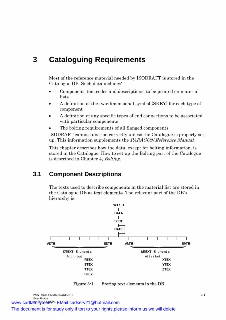
3.1 Component Descriptions
The texts used to describe components in the material list are stored in the Catalogue DB as text elements. The relevant part of the DB’s hierarchy is:
WORLD
CATA
SECT
CATE
ADTE SDTE AMTE SMTE
DTEXT El ement s MTEXT El ement sAt t r i but
RTEXSTEXTTEXSKEY
At t r i butXTEXYTEXZTEX
Figure 3-1 Storing text elements in the DB
VANTAGE PDMS ISODRAFT 3-1 User Guide Version 11.6SP1 www.cadfamily.com EMail:[email protected]
The document is for study only,if tort to your rights,please inform us,we will delete
Cataloguing Requirements
where: ADTE to SDTE are detail text (DTEXT) elements and AMTE to SMTE are material text (MTEXT) elements. Note: Both sets of text elements normally exist at the same level, as
shown, although the DTEXT and MTEXT elements will often be in different sections (SECT) or categories (CATE).
Text elements are created as described in the PARAGON Reference Manual. For example:
NEW DTEXT 17 NEW MTEXT 17 NEW BMTE
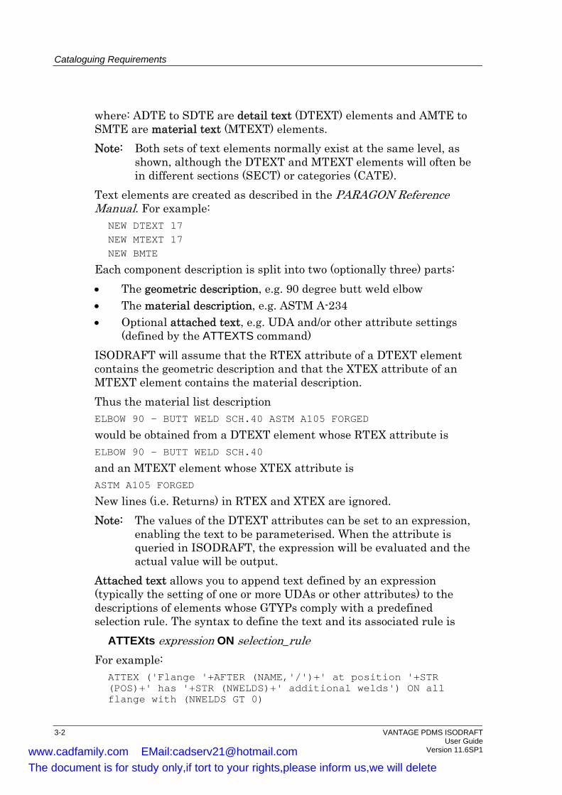
Each component description is split into two (optionally three) parts: • The geometric description, e.g. 90 degree butt weld elbow • The material description, e.g. ASTM A-234 • Optional attached text, e.g. UDA and/or other attribute settings
(defined by the ATTEXTS command) ISODRAFT will assume that the RTEX attribute of a DTEXT element contains the geometric description and that the XTEX attribute of an MTEXT element contains the material description. Thus the material list description ELBOW 90 - BUTT WELD SCH.40 ASTM A105 FORGED
would be obtained from a DTEXT element whose RTEX attribute is ELBOW 90 - BUTT WELD SCH.40
and an MTEXT element whose XTEX attribute is ASTM A105 FORGED
New lines (i.e. Returns) in RTEX and XTEX are ignored. Note: The values of the DTEXT attributes can be set to an expression,
enabling the text to be parameterised. When the attribute is queried in ISODRAFT, the expression will be evaluated and the actual value will be output.
Attached text allows you to append text defined by an expression (typically the setting of one or more UDAs or other attributes) to the descriptions of elements whose GTYPs comply with a predefined selection rule. The syntax to define the text and its associated rule is
ATTEXts expression ON selection_rule For example:
ATTEX ('Flange '+AFTER (NAME,'/')+' at position '+STR (POS)+' has '+STR (NWELDS)+' additional welds') ON all flange with (NWELDS GT 0)
3-2 VANTAGE PDMS ISODRAFT User Guide Version 11.6SP1 www.cadfamily.com EMail:[email protected]
The document is for study only,if tort to your rights,please inform us,we will delete

Cataloguing Requirements
ATTEX ('Colour: ' + :Colour) ON ALL BRANCH MEMBERS
The description shown on the isometric will be RTEX + XTEX + ATTEXT. The ATTEXT syntax may be used as often as required, each expression being evaluated and appended to the description whenever the selection rule returns a True result. The command ATTEXTS NONE cancels all current ATEXT rules.
3.2 Symbol Keys
Each type of component has a two-dimensional symbol which is used to represent it on the isometric drawings. Each symbol is referred to by a text attribute, known as the symbol key (SKEY) attribute, of a DTEXT element. The overall relationship between a pipe component and its descriptive elements is shown by the following structure:
PIPECOMPONENT
SPREF
SPECCOMPONENT
DETAIL
MATXT
DTEXT
RTEXSKEY
MTEXT
XTEX
(SPCOM)
Figure 3-2 Symbol keys
Chapter 3 of the VANTAGE PDMS ISODRAFT Reference Manual contains a complete list of the standard symbols and their associated symbol keys, grouped together by generic type (ELBO, FLAN, PCOM, VALV, etc.). You can usually select any symbol listed under the relevant generic type. For example, the following symbol keys are valid for a CAP (see Section 3.4 of the VANTAGE PDMS ISODRAFT Reference Manual):
KABW KACP KASC KASW
If an incorrect SKEY is specified, a default rectangle will be drawn at the corresponding component position.
VANTAGE PDMS ISODRAFT 3-3 User Guide Version 11.6SP1 www.cadfamily.com EMail:[email protected]
The document is for study only,if tort to your rights,please inform us,we will delete
Cataloguing Requirements
Note: It is essential to comply with the p-point configurations for the given symbol. Chapter 3 of the VANTAGE PDMS ISODRAFT Reference Manual shows the configuration for each symbol.
The SKEY attribute of a DTEXT element is set by using the syntax SKEY symbolkeytext
where symbolkeytext is the symbol key attribute code enclosed between closing quotes. For example:
SKEY ’KABW’
The default SKEY symbols should be suitable for most applications. For specialised needs it is possible to redefine existing symbols, or to create new symbols, for some types of component. This is described in Chapter 10.
3.3 Component End Conditions Defined By P-Points
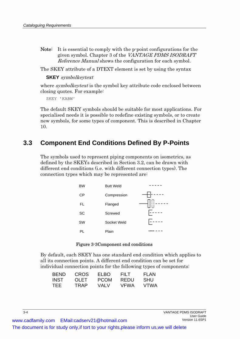
The symbols used to represent piping components on isometrics, as defined by the SKEYs described in Section 3.2, can be drawn with different end conditions (i.e. with different connection types). The connection types which may be represented are:
BW Butt Weld
CP Compression
FL Flanged
SC Screwed
SW Socket Weld
PL Plain
Figure 3-3 Component end conditions
By default, each SKEY has one standard end condition which applies to all its connection points. A different end condition can be set for individual connection points for the following types of components:
BEND CROS ELBO FILT FLAN INST OLET PCOM REDU SHU TEE TRAP VALV VFWA VTWA
3-4 VANTAGE PDMS ISODRAFT User Guide Version 11.6SP1 www.cadfamily.com EMail:[email protected]
The document is for study only,if tort to your rights,please inform us,we will delete
Cataloguing Requirements
P-point elements of type PTAXI, PTCAR and PTMIX have a PSKEY (P-point Symbol Key) attribute which is, by default, set to NULL, so that ISODRAFT uses the standard end connections defined for that SKEY. The end condition for a connection point may be changed in PARAGON by setting the PSKEY of the corresponding p-point to one of connection end conditions shown above. To revert to the default end condition representations for a component, reset its PSKEY attributes to NULL.
3.4 Alternative Item Codes
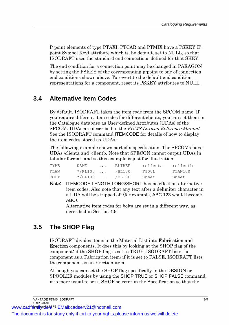
By default, ISODRAFT takes the item code from the SPCOM name. If you require different item codes for different clients, you can set them in the Catalogue database as User-defined Attributes (UDAs) of the SPCOM. UDAs are described in the PDMS Lexicon Reference Manual. See the ISODRAFT command ITEMCODE for details of how to display the item codes stored as UDAs. The following example shows part of a specification. The SPCOMs have UDAs :clienta and :clientb. Note that SPECON cannot output UDAs in tabular format, and so this example is just for illustration. TYPE NAME ... BLTREF :clienta :clientb FLAN */FL100 ... /BL100 F100L FLAN100 BOLT */BL100 ... /BL100 unset unset
Note: ITEMCODE LENGTH LONG/SHORT has no effect on alternative item codes. Also note that any text after a delimiter character in a UDA will be stripped off (for example, ABC:123 would become ABC). Alternative item codes for bolts are set in a different way, as described in Section 4.9.
3.5 The SHOP Flag
ISODRAFT divides items in the Material List into Fabrication and Erection components. It does this by looking at the SHOP flag of the component: if the SHOP flag is set to TRUE, ISODRAFT lists the component as a Fabrication item; if it is set to FALSE, ISODRAFT lists the component as an Erection item. Although you can set the SHOP flag specifically in the DESIGN or SPOOLER modules by using the SHOP TRUE or SHOP FALSE command, it is more usual to set a SHOP selector in the Specification so that the
VANTAGE PDMS ISODRAFT 3-5 User Guide Version 11.6SP1 www.cadfamily.com EMail:[email protected]
The document is for study only,if tort to your rights,please inform us,we will delete

Cataloguing Requirements
flag is set automatically when the component is selected. The default, if the SHOP flag is unset, is SHOP FALSE. Consider, for example, the following Specification. Note: The default for SHOP is shown as =, meaning that the default
setting is taken from the first SPCOM which satisfies all other selectors.
HEADING NAME TYPE PBOR0 ANGL SHOP CATREF DETAIL MATXT DEFAULTS - - - 90.0 = */EA65 ELBO 65.0 90.0 TRUE /AAEA200KK /AAEA200-D /A6B */EC65 ELBO 65.0 45.0 TRUE /AAEC200KK /AAEC200-D /A6B */EA80 ELBO 80.0 90.0 TRUE /AAEA200LL /AAEA200-D /A6B */EC80 ELBO 80.0 45.0 TRUE /AAEC200LL /AAEC200-D /A6B
It is usual for all items except those such as Bolts, Gaskets, Valves, etc. to be designated Fabrication items; i.e. to have the SHOP flag set to TRUE. If you need to make an exception to this convention, for example, to specify a loose flange for field fitting, you can override the SHOP flag during the component selection process thus:
NEW FLAN SEL WITH SHOP FALS
If you wish to use the same component with SHOP either TRUE or FALSE, you can have two lines in the Specification (i.e. two SPCOMs) with the same basic Name but with distinguishing delimiters; for example, */FL100:T and */FL100:F. ISODRAFT ignores the delimiter and shows the same item code for each flange in the material list, i.e. /FL100.
3.5.1 Tube SHOP Flag
ISODRAFT takes the SHOP flag setting for tube from the specification. If the SHOP flag is not specified, the default is FALSE. It is most probable that you will want small bore tube to be treated as an erection item (SHOP FALSE) and larger bore tube to be treated as a fabrication item (SHOP TRUE). It is also important that spool isometrics have tube with SHOP TRUE. To access tubes with the same bore, schedule, material, etc., yet with SHOP TRUE at one point and FALSE at another, it is necessary to have two tube SPCOMs. These will have identical lines in the specification except for their SHOP column entries and their names. You do not want to have two different item codes for the same tube on the isometric, so the names should be identical up to a suffix delimiter (a colon ‘:’ by
3-6 VANTAGE PDMS ISODRAFT User Guide Version 11.6SP1 www.cadfamily.com EMail:[email protected]
The document is for study only,if tort to your rights,please inform us,we will delete
Cataloguing Requirements
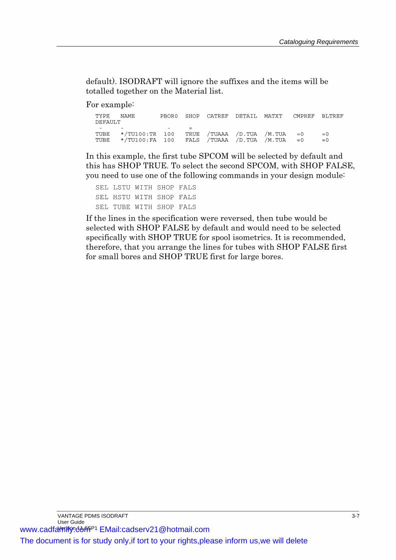
default). ISODRAFT will ignore the suffixes and the items will be totalled together on the Material list. For example:
TYPE NAME PBOR0 SHOP CATREF DETAIL MATXT CMPREF BLTREF DEFAULT - - - = TUBE */TU100:TR 100 TRUE /TUAAA /D.TUA /M.TUA =0 =0 TUBE */TU100:FA 100 FALS /TUAAA /D.TUA /M.TUA =0 =0
In this example, the first tube SPCOM will be selected by default and this has SHOP TRUE. To select the second SPCOM, with SHOP FALSE, you need to use one of the following commands in your design module:
SEL LSTU WITH SHOP FALS SEL HSTU WITH SHOP FALS SEL TUBE WITH SHOP FALS
If the lines in the specification were reversed, then tube would be selected with SHOP FALSE by default and would need to be selected specifically with SHOP TRUE for spool isometrics. It is recommended, therefore, that you arrange the lines for tubes with SHOP FALSE first for small bores and SHOP TRUE first for large bores.
VANTAGE PDMS ISODRAFT 3-7 User Guide Version 11.6SP1 www.cadfamily.com EMail:[email protected]
The document is for study only,if tort to your rights,please inform us,we will delete

Cataloguing Requirements
3-8 VANTAGE PDMS ISODRAFT User Guide Version 11.6SP1
www.cadfamily.com EMail:[email protected] document is for study only,if tort to your rights,please inform us,we will delete
Bolting
4 Bolting
This chapter describes how to set up Bolting information in the Catalogue. For more information about other aspects of setting up the Catalogue for ISODRAFT, see Chapter 3, Cataloguing Requirements.
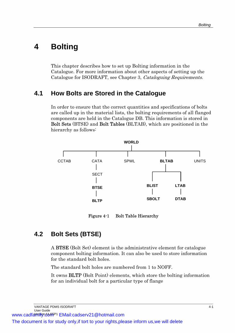
4.1 How Bolts are Stored in the Catalogue
In order to ensure that the correct quantities and specifications of bolts are called up in the material lists, the bolting requirements of all flanged components are held in the Catalogue DB. This information is stored in Bolt Sets (BTSE) and Bolt Tables (BLTAB), which are positioned in the hierarchy as follows:
WORLD
CCTAB CATA BLTABSPWL UNITS
BLIST LTAB
SBOLT DTAB
SECT
BTSE
BLTP
Figure 4-1 Bolt Table Hierarchy
4.2 Bolt Sets (BTSE)
A BTSE (Bolt Set) element is the administrative element for catalogue component bolting information. It can also be used to store information for the standard bolt holes. The standard bolt holes are numbered from 1 to NOFF. It owns BLTP (Bolt Point) elements, which store the bolting information for an individual bolt for a particular type of flange
VANTAGE PDMS ISODRAFT 4-1 User Guide Version 11.6SP1 www.cadfamily.com EMail:[email protected]
The document is for study only,if tort to your rights,please inform us,we will delete
Bolting
4-2 VANTAGE PDMS ISODRAFT User Guide Version 11.6SP1
BLTP should be used for non standard bolt holes and also specifically for jacking bolts. Existing projects which do not use standard bolts will carry on working without problems. Catalogue components can have a Bolt Reference (BLRF) array attribute which points to one or more Bolt Set elements. If a Component has the same bolting requirements for each connection, a single entry in the Bolt Reference array will be sufficient. Otherwise, an entry for each P-point which represents a bolted connection is needed.
Bolt Sets have the following attributes: NOFF Number of standard bolt holes in the bolt circle. BDIA Bolt diameter. BTHK Bolt length through flange (flange thickness and facing
thickness). BTYPE The Bolt type, which is used to select the Bolt from the
specification, and also affects how the bolt length is calculated.
Bolt Points have the following attributes: NUMB Bolt hole number in the bolt circle. BDIA Bolt diameter. BTHK Bolt length through flange (flange thickness and facing
thickness). BTYPE The Bolt type, which is used to select the Bolt from the
specification, and also affects how the bolt length is calculated.
The BDIA, BTHK and BTYPE attributes of Bolt Points can all be set from Catalogue Component or Design parameters.
4.2.1 The Number Attribute (NUMB)
All bolts must have a number, which is stored in the NUMB attribute of the Bolt Point. Bolts must be numbered in order around the bolt circle, except for jacking bolts, which will have NUMB set to zero. Thus bolt number one on a flange will correspond to bolt number one on the connecting valve, and so on (see Figure 4-3). The bolt order must be symmetrical, so that two like flanges can be bolted together when one is reversed. Jacking bolts do not require a matching Bolt Point number on the mating flange.
www.cadfamily.com EMail:[email protected] document is for study only,if tort to your rights,please inform us,we will delete

Bolting
VANTAGE PDMS ISODRAFT 4-3 User Guide Version 11.6SP1
4.2.2 The Bolt Length Attribute (BTHK)
The BTHK (Bolt length) attribute is used as follows: • Components with blind holes have the tapping depth assigned to
their BTHK attributes. • Jacking bolts have their BTHK set to the sum of the flange/facing
thickness and the required opening gap. • Wafer components with no special bolting needs do not require a
Bolt Pointset. If supplied with a Bolt Pointset, a BTHK value of zero indicates that the face-to-face dimension of the wafer component is included in the bolt length calculation.
• Wafer components with special bolting needs require a Bolt Pointset, with BTHK values assigned only to the respective Bolt Points affected. For example, a wafer lug valve with four bolted through holes and four tappings for cap screws on each side requires eight Bolt Points. The four bolted through numbers have their BTHK set to 0. The cap screw numbers have their BTHK set to the tapping depth. See Figure 4-3.
4.3 Bolt Tables
The BLTAB (Bolt table) element is the administrative element for bolting information selected from the bolt specifications. It can own BLIST (Bolt List) and LTAB (Length Table) elements. • The BLIST (bolt list) element is the administrative element which
owns SBOLT (single bolt) elements. Each SBOLT has the following attributes:
NST A pointer to a standard length array BITEM Additional bolt items to be used when calculating bolt
length BITL The lengths of the additional bolt items
• The LTAB (length table) element is the administrative element which owns DTAB (diameter table) elements.
Each DTAB element has a BLEN (bolt length array) attribute containing all available lengths of bolts for a given diameter and material specification. This data is used by ISODRAFT for calculating bolt length requirements. When ISODRAFT calculates that a bolted connection requires a bolt length, it scans the BLEN array for a length which is equal to or greater than the calculated length. The length found is output in the material list.
www.cadfamily.com EMail:[email protected] document is for study only,if tort to your rights,please inform us,we will delete
Bolting
4-4 VANTAGE PDMS ISODRAFT User Guide Version 11.6SP1
Note: Any associated nuts, washers and other bolting items can be included in the material list by adding them to the bolt detail and material descriptions in the catalogue definitions. Nuts and washers can be included in bolt length calculations as described in Section 4.5.5.
4.4 Bolt Specifications
Pipe Specifications have a reference attribute BSPEC, which can be set to a specification containing bolts. Bolts will be selected from the Bolt Specification, if the BSPEC is set, or from the Piping Specification of the flanged component, if it is not set. For bolting across Specification breaks, bolts will be selected from the second Specification if they cannot be selected from the first Specification. The first Specification is defined as the gasket Specification if a gasket is present, otherwise it is defined as the downstream Specification. In the event that bolts are included in vendor supply, for example, an orifice flange assembly, a null BLTREF of CATREF indicates that no bolts will be output for that joint.
4.4.1 Bolt Selection from Specification
Each SBOLT element in the catalogue is referenced by an SPCOM in the Bolt Specification. Bolts are selected individually for each BLTP from the Specification for the appropriate Bolt Diameter and Bolt Type (BTYP). Examples of valid BTYPs are:
MACH machine bolts STU stud bolts CAP cap screws JACK jacking screws TAP tapped holes
A BTYP of BOLT will also be used as a pointer to the default bolt type, set in the specification. This can easily be set by altering the value for BTYP in the DEFAULT column of the specification. This implies that a separate line for each required BTYP must be included in the Specification for each size of bolt. The way the selection works is explained in the following rules: • If the BTYP for both sides of a joint is set to BOLT, the default bolt
of the given diameter is used. • If the BTYP for one side of the joint is set to BOLT and the other
side is set to anything other than BOLT, the type of bolt specified by
www.cadfamily.com EMail:[email protected] document is for study only,if tort to your rights,please inform us,we will delete
Bolting
VANTAGE PDMS ISODRAFT 4-5 User Guide Version 11.6SP1
that BTYP will be used. For example, a bolted through flange may have its BTYP set to BOLT, and the mating flange may require cap screws and have its BTYP set to CAP. In this case, the cap screw overrides the default type, and the selected BTYP will be CAP.
• If both BTYPs are the same and are not set to BOLT, the bolt with that BTYP is selected.
• If the BTYPs are not equal and are also not set to BOLT, the BTYP from the start of the bolt is selected.
4.4.2 Bolts SHOP Flag
ISODRAFT takes the SHOP flag setting for bolts from the specification. The BOLT SPCOM should be defined with a SHOP selector column. If the SHOP flag is not specified, its setting defaults to FALSE. If the same bolt is to appear in both fabrication and erection lists, two SPCOMs must be defined which are the same up to a suffix delimiter, in the same way as for tube. Also, two flanges must be defined using the delimiter character, in order to reference the two bolts. The flanges will be totalled together if they are to appear in the same section of the material list. For example:
TYPE NAME PBORO SHOP CATREF DETAIL MATXT CMPREF BLTREF DEFAULT - - - = = FLAN */FW100:TR 100 TRUE /FWAAA /D.FWA /M.FWA =0 /SBOL100T FLAN */FW100:FA 100 FALS /FWAAA /D.FWA /M.FWA =0 /SBOL100F . . . TYPE NAME PBORO SHOP CATREF DETAIL MATXT CMPREF BLTREF DEFAULT - - - = = BOLT */BL100:TR 100 TRUE /BLAAA /D.BLA /M.BLA =0 /SBOL100T BOLT */BL100:FA 100 FALS /BLAAA /D.BLA /M.BLA =0 /SBOL100F
This example will give bolts in the same part of the material list (fabrication or erection) as the flange with SHOP TRUE or SHOP FALSE (default TRUE in this example). The following example will give bolts in either list but total the flanges together in the fabrication list, by selecting the flange with BOLT SHOP or BOLT SITE. Note that item codes that are identical after removal of the specification name and the characters following the delimiter will be totalled together.
www.cadfamily.com EMail:[email protected] document is for study only,if tort to your rights,please inform us,we will delete
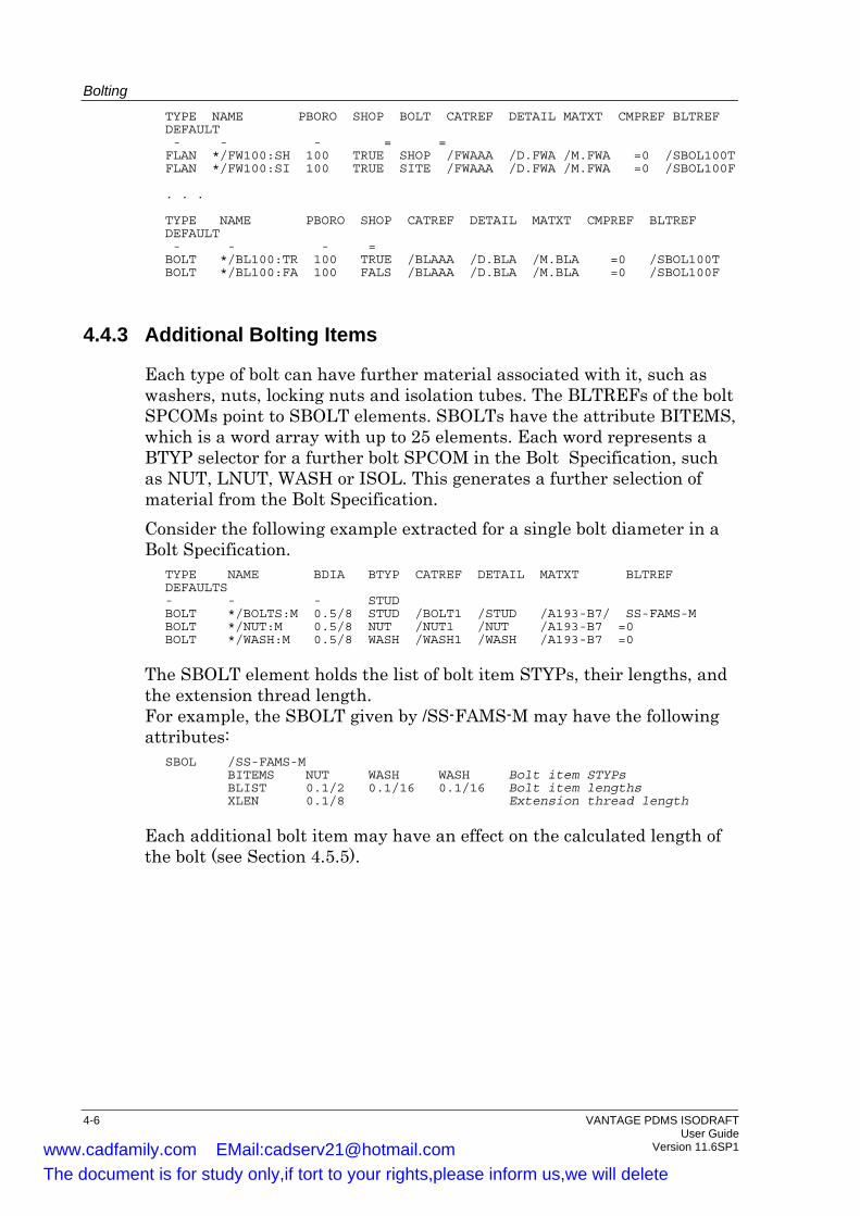
Bolting
4-6 VANTAGE PDMS ISODRAFT User Guide Version 11.6SP1
TYPE NAME PBORO SHOP BOLT CATREF DETAIL MATXT CMPREF BLTREF DEFAULT - - - = = FLAN */FW100:SH 100 TRUE SHOP /FWAAA /D.FWA /M.FWA =0 /SBOL100T FLAN */FW100:SI 100 TRUE SITE /FWAAA /D.FWA /M.FWA =0 /SBOL100F . . . TYPE NAME PBORO SHOP CATREF DETAIL MATXT CMPREF BLTREF DEFAULT - - - = BOLT */BL100:TR 100 TRUE /BLAAA /D.BLA /M.BLA =0 /SBOL100T BOLT */BL100:FA 100 FALS /BLAAA /D.BLA /M.BLA =0 /SBOL100F
4.4.3 Additional Bolting Items
Each type of bolt can have further material associated with it, such as washers, nuts, locking nuts and isolation tubes. The BLTREFs of the bolt SPCOMs point to SBOLT elements. SBOLTs have the attribute BITEMS, which is a word array with up to 25 elements. Each word represents a BTYP selector for a further bolt SPCOM in the Bolt Specification, such as NUT, LNUT, WASH or ISOL. This generates a further selection of material from the Bolt Specification. Consider the following example extracted for a single bolt diameter in a Bolt Specification.
TYPE NAME BDIA BTYP CATREF DETAIL MATXT BLTREF DEFAULTS - - - STUD BOLT */BOLTS:M 0.5/8 STUD /BOLT1 /STUD /A193-B7/ SS-FAMS-M BOLT */NUT:M 0.5/8 NUT /NUT1 /NUT /A193-B7 =0 BOLT */WASH:M 0.5/8 WASH /WASH1 /WASH /A193-B7 =0
The SBOLT element holds the list of bolt item STYPs, their lengths, and the extension thread length. For example, the SBOLT given by /SS-FAMS-M may have the following attributes:
SBOL /SS-FAMS-M BITEMS NUT WASH WASH Bolt item STYPs BLIST 0.1/2 0.1/16 0.1/16 Bolt item lengths XLEN 0.1/8 Extension thread length
Each additional bolt item may have an effect on the calculated length of the bolt (see Section 4.5.5).
www.cadfamily.com EMail:[email protected] document is for study only,if tort to your rights,please inform us,we will delete
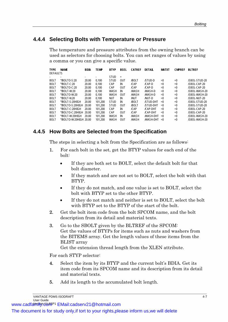
Bolting
VANTAGE PDMS ISODRAFT 4-7 User Guide Version 11.6SP1
4.4.4 Selecting Bolts with Temperature or Pressure
The temperature and pressure attributes from the owning branch can be used as selectors for choosing bolts. You can set ranges of values by using a comma or you can give a specific value.
TYPE NAME BDIA TEMP BTYP BSEL CATREF DETAIL MATXT CMPREF BLTREF DEFAULTS - - - - STUD = BOLT */BOLTO-S:20 20.00 0,100 STUD OUT /BOLT /STUD-D =0 =0 /SBOL-STUD-20 BOLT */BOLT-C:20 20.00 0,100 CAP IN /CAP /CAP-D =0 =0 /SBOL-CAP-20 BOLT */BOLTO-C:20 20.00 0,100 CAP OUT /CAP /CAP-D =0 =0 /SBOL-CAP-20 BOLT */BOLT-W:20 20.00 0,100 WASH IN /WASH /WASH-D =0 =0 /SBOL-WASH-20 BOLT */BOLTO-W:20 20.00 0,100 WASH OUT /WASH /WASH-D =0 =0 /SBOL-WASH-20 BOLT */BOLT-N:20 20.00 0,100 NUT IN /NUT /NUT-D =0 =0 /SBOL-NUT-20 BOLT */BOLT-S:20HIGH 20.00 101,200 STUD IN /BOLT /STUD-DHT =0 =0 /SBOL-STUD-20 BOLT */BOLTO-S:20HIGH 20.00 101,200 STUD OUT /BOLT /STUD-DHT =0 =0 /SBOL-STUD-20 BOLT */BOLT-C:20HIGH 20.00 101,200 CAP IN /CAP /CAP-DHT =0 =0 /SBOL-CAP-20 BOLT */BOLTO-C:20HIGH 20.00 101,200 CAP OUT /CAP /CAP-DHT =0 =0 /SBOL-CAP-20 BOLT */BOLT-W:20HIGH 20.00 101,200 WASH IN /WASH /WASH-DHT =0 =0 /SBOL-WASH-20 BOLT */BOLTO-W:20HIGH 20.00 101,200 WASH OUT /WASH /WASH-DHT =0 =0 /SBOL-WASH-20
4.4.5 How Bolts are Selected from the Specification
The steps in selecting a bolt from the Specification are as follows: 1. For each bolt in the set, get the BTYP values for each end of the
bolt: • If they are both set to BOLT, select the default bolt for that
bolt diameter. • If they match and are not set to BOLT, select the bolt with that
BTYP. • If they do not match, and one value is set to BOLT, select the
bolt with BTYP set to the other BTYP. • If they do not match and neither is set to BOLT, select the bolt
with BTYP set to the BTYP of the start of the bolt. 2. Get the bolt item code from the bolt SPCOM name, and the bolt
description from its detail and material texts. 3. Go to the SBOLT given by the BLTREF of the SPCOM:
Get the values of BTYPs for items such as nuts and washers from the BITEMS array. Get the length values of these items from the BLIST array Get the extension thread length from the XLEN attribute.
For each STYP selector: 4. Select the item by its BTYP and the current bolt’s BDIA. Get its
item code from its SPCOM name and its description from its detail and material texts.
5. Add its length to the accumulated bolt length.
www.cadfamily.com EMail:[email protected] document is for study only,if tort to your rights,please inform us,we will delete
Bolting
4-8 VANTAGE PDMS ISODRAFT User Guide Version 11.6SP1
6. Add the extension thread length to the accumulated bolt length 7. Go to the NSTD length table. If the accumulated length is within
1mm over an available length from the BLEN array, then round down, else round up. If the NSTD reference is NULL, use the actual BLEN of the SBOLT, since this is intended as a pre-set length for special purposes, for example, a large flange with exact torque requirements.
8. Include the bolt length in the item code and description in accordance with the existing ISODRAFT options.
When the bolt member count has been satisfied, combine the data to obtain totals of like bolt items in the material list. See Section 8.7. Any error conditions such as a bolt item cannot be selected, or there are no long enough lengths in the NSTD table, will cause the system to generate an error message, output a material description of ‘‘Bolts undefined” for that joint (with zero item code, size and quantity), and continue detailing.
4.5 Bolt Length Calculation
The calculated length of a bolt to be used to secure a joint has to take account of various factors, as explained in the following sections.
4.5.1 Bolt Length Calculation for Standard Flange-Gasket-Flange
The calculation of bolts will be triggered by the presence of a connection type starting with F (flange face) or L (lap joint), and will be completed by a second occurrence of such a connection type. The calculation steps are: 1. At the first component, go to the CATREF, and find the BTSE name
assigned in the BLRF for the appropriate p-point of the component. Store this reference (BTSE1).
2. Go to the second component. If its connection type starts with G (a gasket), get its P1 - P2 distance, and go to the next component.
3. If its connection type starts with F or L, go to the CATREF, and find the BTSE name assigned in the BLRF for the appropriate p-point of the component. Store this reference (BTSE2).
4. Check for matching member counts of BTSE1 and BTSE2 (excluding jacking bolts, that is with BTYP JACK).
For each bolt in the set: 5. Get the Bolt Points with corresponding NUMBer.
www.cadfamily.com EMail:[email protected] document is for study only,if tort to your rights,please inform us,we will delete
Bolting
VANTAGE PDMS ISODRAFT 4-9 User Guide Version 11.6SP1
6. Check for matching BDIA values. 7. Add the two values of BTHK (bolted flange thickness) together. 8. Add the gasket thickness (if found). 9. Select the bolt from the Specification and obtain its standard
(rounded up) length. See Section 4.4.2. The following error conditions generate an error message, output a material description of ‘‘Bolts undefined” for that joint (with zero item code, size and quantity), and continue detailing. • No valid BOLTREF of CATREF for the second flange • Unequal number of members for BTSE1 and BTSE2, excluding
jacking bolts • Mismatch in BDIA attributes between equivalent members of
BTSE1 and BTSE2
4.5.2 Bolt Length Calculation for General Wafer Components
The calculation of bolts through wafer components is similar to the standard flange-gasket-flange calculation, with the following differences: • If within the joint, a component’s connection type starts with W
(wafer), get its P1 - P2 distance, and go to the next component. • The joint may contain any number of wafer components, (for
example, butterfly valves, orifice plates, spectacle plates, spades) and any number of gaskets. The total bolted through length will be summed and added to the flange thickness.
4.5.3 Bolt Length Calculation for Components with Mixed Bolt Needs
The calculation of bolts through components with mixed bolt needs is the same as the general wafer calculation, but allows for different bolts in the set to start and stop at different places within the joint. If a wafer component has a BLRF of CATREF, and the BTHK value for a particular bolt is not zero, then the specified thickness is used in the calculation. If the BTYP of the bolt is JACK, TAP or CAP, this will complete that particular bolt. A subsequent BTYP of JACK, TAP or CAP for the same bolt NUMBer further on in the joint triggers a new bolt. This allows for such a situation as a wafer lug valve, with some bolts going through the whole joint, and some cap screws on either side bolting into the body of the valve (see Figure 4-3). Bolts are selected from the Specification as normal, but each bolt path through the joint will be able to start and stop at different points within
www.cadfamily.com EMail:[email protected] document is for study only,if tort to your rights,please inform us,we will delete
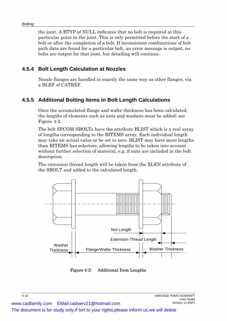
Bolting
the joint. A BTYP of NULL indicates that no bolt is required at this particular point in the joint. This is only permitted before the start of a bolt or after the completion of a bolt. If inconsistent combinations of bolt path data are found for a particular bolt, an error message is output, no bolts are output for that joint, but detailing will continue.
4.5.4 Bolt Length Calculation at Nozzles
Nozzle flanges are handled in exactly the same way as other flanges, via a BLRF of CATREF.
4.5.5 Additional Bolting Items in Bolt Length Calculations
Once the accumulated flange and wafer thickness has been calculated, the lengths of elements such as nuts and washers must be added; see Figure 4-2. The bolt SPCOM SBOLTs have the attribute BLIST which is a real array of lengths corresponding to the BITEMS array. Each individual length may take an actual value or be set to zero. BLIST may have more lengths than BITEMS has selectors, allowing lengths to be taken into account without further selection of material, e.g. if nuts are included in the bolt description. The extension thread length will be taken from the XLEN attribute of the SBOLT and added to the calculated length.
Nut Length
Extension Thread Length
Flange/Wafer ThicknessWasher
Thickness Washer Thickness
Figure 4-2: Additional Item Lengths
4-10 VANTAGE PDMS ISODRAFT User Guide Version 11.6SP1 www.cadfamily.com EMail:[email protected]
The document is for study only,if tort to your rights,please inform us,we will delete

Bolting
VANTAGE PDMS ISODRAFT 4-11 User Guide Version 11.6SP1
4.6 Part Numbers and Tags
If part numbers have been set in SPOOLER, you can specify that these numbers are used on the material list, or that ISODRAFT will generate part numbers automatically. • If part numbers generated by ISODRAFT are used, like bolt items
will be totalled in the material list. • If part numbers from the database are used, one part number is
allocated to each type of bolt item in an individual bolt set, i.e. if all bolt items in a set are identical, there will be a single part number for the set.
For more information about part numbers, see the MATERIALLIST command in Chapter 2 of the VANTAGE PDMS ISODRAFT Reference Manual. Multiple bolt item part numbers tagged to the same location will be combined as for additional items on the material list; for example, B10/B11/B12.
4.7 Example Wafer Lug Valve
The diagram below illustrates the wafer lug valve scenario. This example shows a wafer valve requiring a set of 12 bolts. There are: • 4 machine bolts which pass through the whole joint from one flange
to the other (Numbers 2, 3, 6, 7). • 4 cap screws on each side of the valve, which secure the valve to the
flanges (Numbers 1, 4, 5, 8). The machine bolt lengths are based on the combined thickness of the two flanges, both gaskets, and the valve itself. The cap screw lengths are based on the thickness of a single flange and gasket combined with the tapping depth in the valve body.
www.cadfamily.com EMail:[email protected] document is for study only,if tort to your rights,please inform us,we will delete
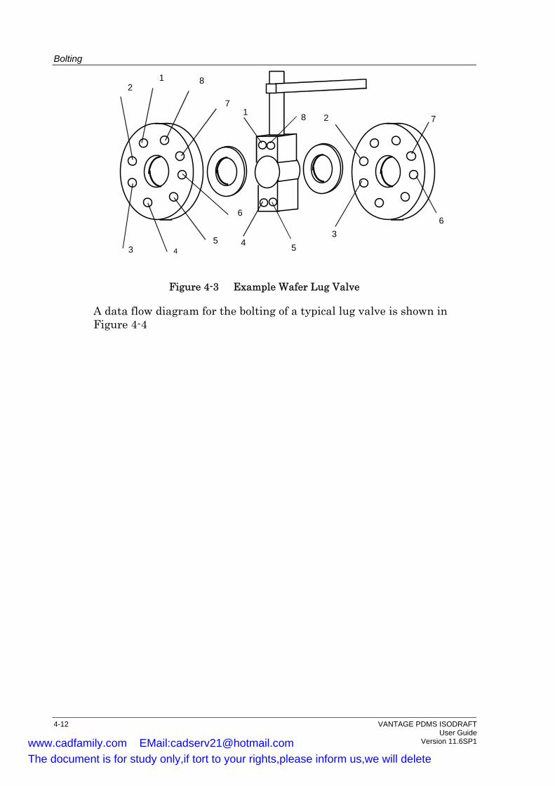
Bolting
12
3 45
6
7
8
1 2
34 5
6
78
Figure 4-3 Example Wafer Lug Valve
A data flow diagram for the bolting of a typical lug valve is shown in Figure 4-4
4-12 VANTAGE PDMS ISODRAFT User Guide Version 11.6SP1 www.cadfamily.com EMail:[email protected]
The document is for study only,if tort to your rights,please inform us,we will delete
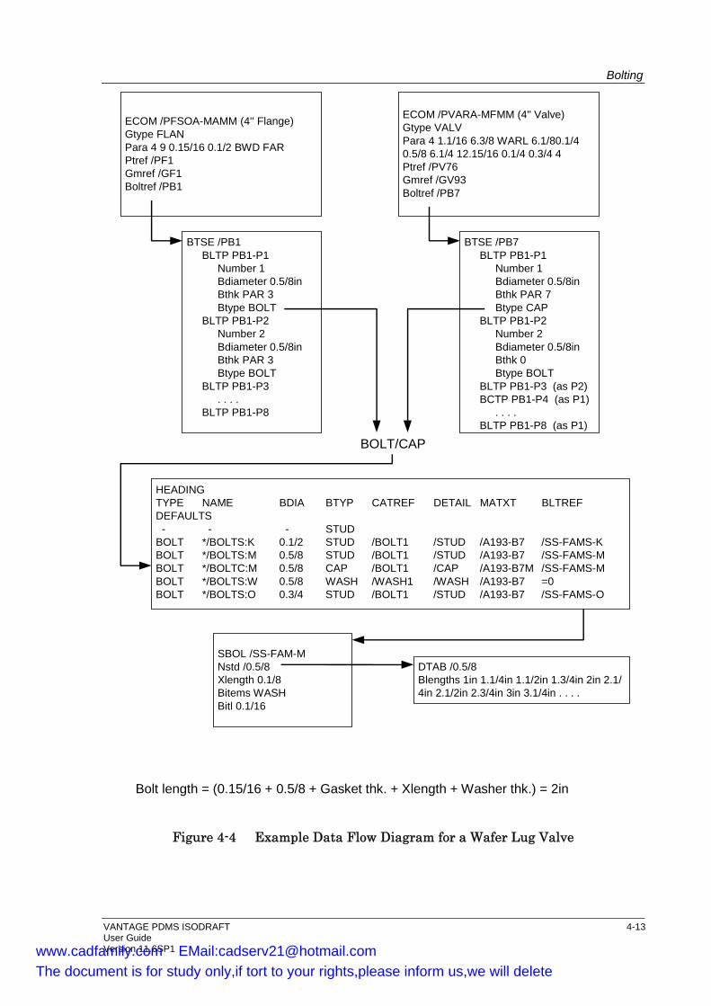
Bolting
ECOM /PFSOA-MAMM (4'' Flange)Gtype FLANPara 4 9 0.15/16 0.1/2 BWD FARPtref /PF1Gmref /GF1Boltref /PB1
ECOM /PVARA-MFMM (4'' Valve)Gtype VALVPara 4 1.1/16 6.3/8 WARL 6.1/80.1/40.5/8 6.1/4 12.15/16 0.1/4 0.3/4 4Ptref /PV76Gmref /GV93Boltref /PB7
BTSE /PB1BLTP PB1-P1
Number 1Bdiameter 0.5/8inBthk PAR 3Btype BOLT
BLTP PB1-P2Number 2Bdiameter 0.5/8inBthk PAR 3Btype BOLT
BLTP PB1-P3. . . .
BLTP PB1-P8
BTSE /PB7BLTP PB1-P1
Number 1Bdiameter 0.5/8inBthk PAR 7Btype CAP
BLTP PB1-P2Number 2Bdiameter 0.5/8inBthk 0Btype BOLT
BLTP PB1-P3 (as P2)BCTP PB1-P4 (as P1)
. . . .BLTP PB1-P8 (as P1)
BOLT/CAP
HEADINGTYPE NAME BDIA BTYP CATREF DETAIL MATXT BLTREFDEFAULTS - - - STUDBOLT */BOLTS:K 0.1/2 STUD /BOLT1 /STUD /A193-B7 /SS-FAMS-KBOLT */BOLTS:M 0.5/8 STUD /BOLT1 /STUD /A193-B7 /SS-FAMS-MBOLT */BOLTC:M 0.5/8 CAP /BOLT1 /CAP /A193-B7M /SS-FAMS-MBOLT */BOLTS:W 0.5/8 WASH /WASH1 /WASH /A193-B7 =0BOLT */BOLTS:O 0.3/4 STUD /BOLT1 /STUD /A193-B7 /SS-FAMS-O
SBOL /SS-FAM-MNstd /0.5/8Xlength 0.1/8Bitems WASHBitl 0.1/16
DTAB /0.5/8Blengths 1in 1.1/4in 1.1/2in 1.3/4in 2in 2.1/4in 2.1/2in 2.3/4in 3in 3.1/4in . . . .
Bolt length = (0.15/16 + 0.5/8 + Gasket thk. + Xlength + Washer thk.) = 2in
Figure 4-4 Example Data Flow Diagram for a Wafer Lug Valve
VANTAGE PDMS ISODRAFT 4-13 User Guide Version 11.6SP1 www.cadfamily.com EMail:[email protected]
The document is for study only,if tort to your rights,please inform us,we will delete
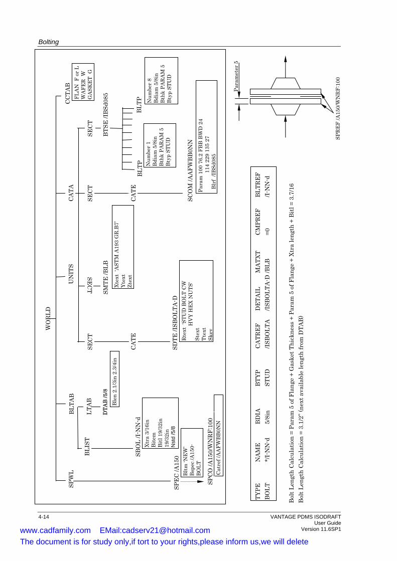
Bolting
4-14 VANTAGE PDMS ISODRAFT User Guide Version 11.6SP1
Para
met
er 5
SPR
EF
/A15
0/W
NR
F:10
0
Bol
t Len
gth
Cal
cula
tion
= Pa
ram
5 o
f Fla
nge
+ G
aske
t Thi
ckne
ss +
Par
am 5
of F
lang
e +
Xtra
leng
th +
Bitl
= 3
.7/1
6 B
olt L
engt
h C
alcu
latio
n =
3.1/
2” (n
ext a
vaila
ble
leng
th fr
om D
TAB
)
TYPE
N
AM
E
BD
IA
BTY
P C
ATR
EF
DE
TAIL
M
ATX
T C
MPR
EF
BLT
RE
F B
OLT
*/
I-N
N-d
5/
8in
STU
D
/ISB
OLT
A
/ISB
OLT
A-D
/BLB
=0
/I
-NN
-d
WO
RLD
BTS
E /I
BSd
085
BLT
P Num
ber
8 B
diam
5/8
in
Bth
k PA
RA
M 5
B
typ
STU
D
BLT
P Num
ber
1 B
diam
5/8
in
Bth
k PA
RA
M 5
B
typ
STU
D
SEC
T
CA
TE
SCO
M /A
AFW
BB
0NN
Pa
ram
100
76.
2 FB
B B
WD
24
114
229
135
27
Blr
f /IB
Sd08
5
CA
TA
UN
ITS
SEC
T SE
CT
SEC
T
SDTE
/ISB
OLT
A-D
R
text
‘ST
UD
BO
LT C
W
H
VY
HE
X N
UTS
’ St
ext
Ttex
t Sk
ey
SMTE
/BLB
Xt
ext
‘AST
M A
193
GR
.B7’
Yt
ext
Ztex
t
BLT
AB
LTA
B
DTA
B /5
/8
Ble
n 2.
1/3i
n 2.
3/4i
n
BLI
ST
SBO
L /I-
NN
-d
Xtra
3/1
6in
Bite
m
Bitl
19/
32in
19
/32i
n N
std
/5/8
SPW
L
SPE
C /A
150
CC
TAB
FL
AN
F o
r L
WA
FER
W
GA
SKE
T G
Cat
ref /
AA
FWB
B0N
N
Bltm
‘NE
W’
Bsp
ec /A
150-
BO
LT
CA
TE
SPC
O /A
150/
WN
RF:
100
www.cadfamily.com EMail:[email protected] document is for study only,if tort to your rights,please inform us,we will delete
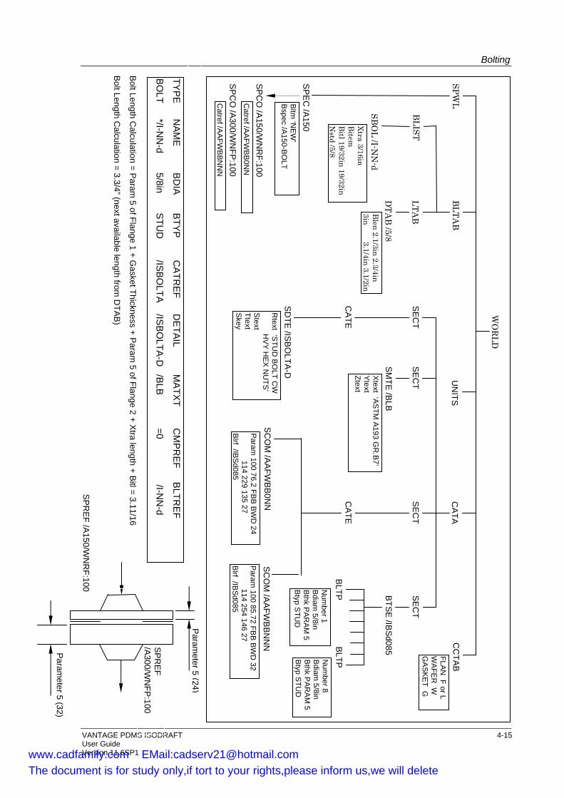
Bolting
VANTAGE PDMS ISODRAFT 4-15
SP
CO
/A300/W
NFP
:100
SP
CO
/A150/W
NR
F:100
Param
eter5(24)
SP
RE
F /A150/W
NR
F:100
SP
RE
F /A
300/WN
FP:100
Param
eter 5 (32)
BO
LT */I-N
N-d
5/8in S
TUD
/IS
BO
LTA
/ISB
OLTA
-D
/BLB
=0
/I-NN
-d
TYP
E
NA
ME
B
DIA
B
TYP
C
ATR
EF
DE
TAIL
MA
TXT
CM
PR
EF
BLTR
EF
WO
RLD
BTS
E /IB
Sd085B
LTPNum
ber 8 B
diam 5/8in
Bthk P
AR
AM
5 B
typ STU
D
BLTPN
umber 1
Bdiam
5/8in B
thk PA
RA
M 5
Btyp S
TUD
SE
CT
CA
TE
SC
OM
/AA
FWB
B0N
NP
aram 100 76.2 FB
B B
WD
24 114 229 135 27 B
lrf /IBS
d085
Param
100 85.72 FBB
BW
D 32
114 254 146 27 B
lrf /IBS
d085
SC
OM
/AA
FWB
BN
NN
CA
TAU
NITS
SE
CT
SE
CT
SE
CT
SD
TE /IS
BO
LTA-D
R
text ‘STU
D B
OLT C
W
HV
Y H
EX
NU
TS’
Stext
Ttext S
key
SM
TE /B
LB
Xtext ‘A
STM
A193 G
R.B
7’Y
text Ztext
BLTA
B
LTAB
DTA
B /5/8
Blen 2.1/3in 2.3/4in
3in 3.1/4in 3.1/2in
BLIST
SBO
L /I-NN
-d Xtra 3/16in B
item
Bitl 19/32in 19/32in
Nstd /5/8
SPWL
SP
EC
/A150
Bltm
‘NE
W’
Bspec /A
150-BO
LT
Catref /A
AFW
BB
0NN
Catref /A
AFW
BB
NN
N
CA
TE
CC
TAB
FLAN
F or L W
AFE
R W
G
AS
KE
T G
Bolt Length Calculation = 3.3/4” (next available length from
DTA
B)
Bolt Length C
alculation = Param
5 of Flange 1 + Gasket Thickness + P
aram 5 of Flange 2 + X
tra length + Bitl = 3.11/16
User Guide Version 11.6SP1 www.cadfamily.com EMail:[email protected]
The document is for study only,if tort to your rights,please inform us,we will delete
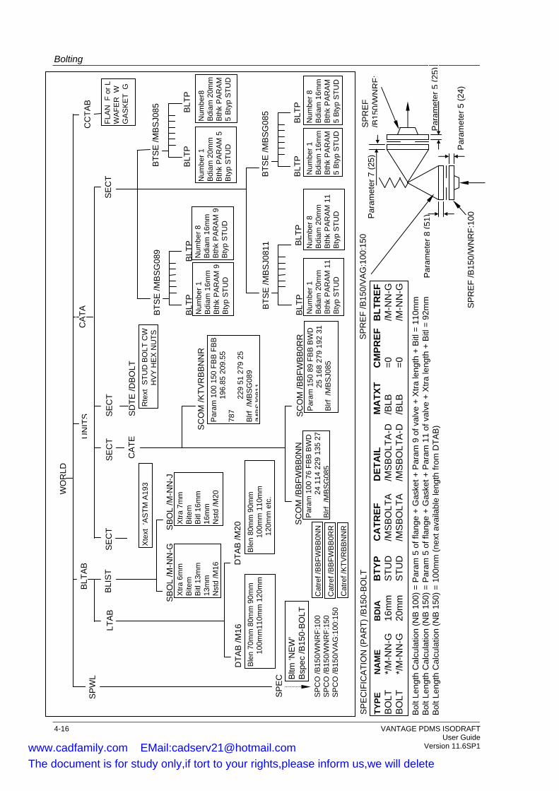
Bolting
Par
am et
er 5
(24)
Par
amet
er8
(51)P
aram
eter
7 (2
5)
Par
amet
er5
(25)
SP
RE
F /B
150/
WN
RF:
100
SP
RE
F
/B15
0/W
NR
F:S
PE
CIF
ICA
TIO
N (P
AR
T) /B
150-
BO
LT
WO
RLD
BTS
E /M
BS
J085
BLT
P
Num
ber8
B
diam
20m
m
Bth
k P
AR
AM
5
Bty
p S
TUD
BLT
P
Num
ber 1
B
diam
20m
m
Bth
k P
AR
AM
5
Bty
p S
TUD
SE
CT
CA
TE
SC
OM
/BB
FWB
B0R
R
Par
am 1
50 8
9 FB
B B
WD
25
168
279
192
31
Blrf
/M
BS
J085
CA
TA
UN
ITS
SE
CT
SE
CT
SD
TE /D
BO
LT
Rte
xt S
TUD
BO
LT C
W
H
VY
HE
X N
UTS
X
text
‘A
STM
A19
3
BLT
AB
LTA
B
DTA
B /M
16
BLI
ST
SB
OL
/M-N
N-G
X
tra 6
mm
B
item
B
itl 1
3mm
13
mm
N
std
/M16
SP
WL
SP
EC
CC
TAB
TYPE
N
AM
E B
DIA
B
TYP
CA
TREF
D
ETA
IL
MA
TXT
CM
PREF
B
LTR
EF
BO
LT
*/M
-NN
-G
16m
m
STU
D
/MS
BO
LTA
/M
SB
OLT
A-D
/B
LB
=0
/M-N
N-G
B
OLT
*/
M-N
N-G
20
mm
S
TUD
/M
SB
OLT
A
/MS
BO
LTA
-D
/BLB
=0
/M
-NN
-G
FLA
N F
or L
W
AFE
R W
G
AS
KE
T G
SP
RE
F /B
150/
VA
G:1
00:1
50
SC
OM
/BB
FWB
B0N
N
Par
am 1
00 7
6 FB
B B
WD
24
114
229
135
27
Blrf
/MB
SG
085
SC
OM
/KTV
RB
BN
NR
P
aram
100
150
FB
B F
BB
196
.85
209.
55
787
2
29 5
1 27
9 25
B
lrf /
MB
SG
089
/MB
SJ0
811
BTS
E /M
BS
G08
5
BLT
P
Num
ber 8
B
diam
16m
m
Bth
k P
AR
AM
5
Bty
p S
TUD
BLT
P
Num
ber 1
B
diam
16m
m
Bth
k P
AR
AM
5
Bty
p S
TUD
SB
OL
/M-N
N-J
X
tra 7
mm
B
item
B
itl 1
6mm
16
mm
N
std
/M20
DTA
B /M
20
Ble
n 80
mm
90m
m
100
mm
110
mm
1
20m
m e
tc.
Ble
n 70
mm
80m
m 9
0mm
100m
m11
0mm
120
mm
BTS
E /M
BS
G08
9
BLT
P
Num
ber 8
B
diam
16m
m
Bth
k P
AR
AM
9
Bty
p S
TUD
BLT
P
Num
ber 1
B
diam
16m
m
Bth
k P
AR
AM
9
Bty
p S
TUD
BTS
E /M
BS
J081
1 BLT
P
Num
ber 8
B
diam
20m
m
Bth
k P
AR
AM
11
Bty
p S
TUD
BLT
P
Num
ber 1
B
diam
20m
m
Bth
k P
AR
AM
11
Bty
p S
TUD
SE
CT
SP
CO
/B15
0/W
NR
F:10
0 S
PC
O /B
150/
WN
RF:
150
SP
CO
/B15
0/V
AG
:100
:150
Bltm
‘NE
W’
Bsp
ec /B
150-
BO
LT
Bol
t Len
gth
Cal
cula
tion
(NB
100
) = P
aram
5 o
f fla
nge
+ G
aske
t + P
aram
9 o
f val
ve +
Xtra
leng
th +
Bitl
= 1
10m
m
Bol
t Len
gth
Cal
cula
tion
(NB
150
) = P
aram
5 o
f fla
nge
+ G
aske
t + P
aram
11
of v
alve
+ X
tra le
ngth
+ B
itl =
92m
m
Bol
t Len
gth
Cal
cula
tion
(NB
150
) = 1
00m
m (n
ext a
vaila
ble
leng
th fr
om D
TAB
)
Cat
ref /
BB
FWB
B0N
N
Cat
ref /
BB
FWB
B0R
R
Cat
ref /
KTV
RB
BN
NR
4-16 VANTAGE PDMS ISODRAFT User Guide Version 11.6SP1 www.cadfamily.com EMail:[email protected]
The document is for study only,if tort to your rights,please inform us,we will delete
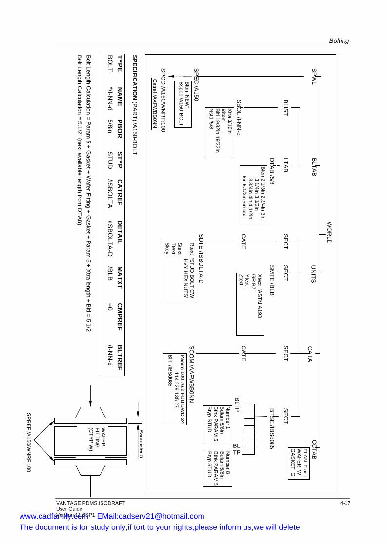
Bolting
User Guide Version 11.6SP1
Param
eter 5
WO
RLD
BTS
E /IB
Sd085BL
TPNum
ber 8 B
diam 5/8in
Bthk P
AR
AM
5 B
typ STU
D
BLTPN
umber 1
Bdiam
5/8in B
thk PA
RA
M 5
Btyp S
TUD
SE
CT
CA
TE
SC
OM
/AA
FWB
B0N
NP
aram 100 76.2 FB
B B
WD
24 114 229 135 27 B
lrf /IBS
d085
CA
TAU
NITS
SE
CT
SE
CT
SE
CT
SD
TE /IS
BO
LTA-D
R
text ‘STU
D B
OLT C
W H
VY
HE
X N
UTS
’S
text Ttext S
key
SM
TE /B
LB
Xtext ‘A
STM
A193
GR
.B7’
Ytext
Ztext
BLTA
B
LTAB
DTA
B /5/8
Blen 2.1/3in 2.3/4in 3in
3.1/4in 3.1/2in 3.3/4in 4in 4.1/2in 5in 5.1/2in 6in etc.
BLIS
T
SB
OL /I-N
N-d
Xtra 3/16in
Bitem
B
itl 19/32in 19/32in N
std /5/8
SP
WL B
ltm ‘N
EW
’ B
spec /A150-B
OLT
SP
CO
/A150/W
NR
F:100 C
atref /AA
FWB
B0N
N
SP
EC
/A150
CA
TE
FLAN
F or L W
AFE
R W
GA
SK
ET G
CC
TAB
SPECIFIC
ATIO
N (P
AR
T) /A150-B
OLT
SP
RE
F /A150/W
NR
F:100
WA
FER
FITTIN
G
(CTY
P W
)
Bolt Length Calculation = 5.1/2” (next available length from
DTA
B)
Bolt Length C
alculation = Param
5 + Gasket + W
afer Fitting + Gasket + P
aram 5 + X
tra length + Bitl = 5.1/2
BO
LT */I-N
N-d
5/8in S
TUD
/IS
BO
LTA
/ISB
OLTA
-D
/BLB
=0
/I-NN
-d TYPE
NA
ME
PBO
R
STYP C
ATR
EF D
ETAIL
MA
TXT C
MPR
EF B
LTREF
VANTAGE PDMS ISODRAFT 4-17
www.cadfamily.com EMail:[email protected] document is for study only,if tort to your rights,please inform us,we will delete

Bolting
4.8 Administrative and Geographical Use of Selectors
In addition to Bolt Specific Type and Diameter, a further degree of bolt selection is allowed via the BSEL attribute of a branch member. This takes a value which can be used as the answer to a BSEL selector in the Bolt Specification. For example, if the Pipe Specification dictates that the same flange has black bolts indoors and galvanised bolts outdoors, then BSEL could be set to either IN or OUT at the flange, with entries for both bolts in the Bolt Specification. Any inconsistency in BSEL attributes between the two ends of the joint causes the system to generate an error message, output a material description of ‘‘Bolts undefined” for that joint (with zero item code, size and quantity), and continue detailing. A further application of this assists in the selection of isolation kits. A flange may require an isolation kit in certain duties and not others. The kit may require longer bolts to cater for isolating washers. A different flange BSEL value will cause a Bolt SPCOM to be selected which has an SBOLT that includes isolating washers in its additional items arrays.
4.9 Alternative Item codes for Bolts
Alternative item codes for bolts are taken from UDAs set on DTAB elements, not on the SPCOM like other elements (see Section 3.4). Note: For additional bolting items such as washers and nuts, the UDA
must be set on SPCOM because these items do not have associated DTAB elements.
Alternative item codes for bolts are set up as follows: • The SBOLT elements must have NSTD attributes pointing to the
DTAB elements. • The names of the UDAs on the DTAB elements must be related to
the UDAs set for the SPCOM. For example, if the SPCOM UDAs are named: clienta and :clientb, there could be one set of DTAB UDAs named :clienta1,:clienta2, etc. and another set of UDAs named clientb1, clientb2, etc.
• The item codes are stored in the DTAB UDAs as texts separated by spaces. As text UDAs have an upper limit of 120 characters, the list of item codes continues across the set of UDAs. For example, if each item code is 10 characters in length, then 11 item codes can be stored in each UDA of the set.
VANTAGE PDMS ISODRAFT 4-18 User Guide Version 11.6SP1 www.cadfamily.com EMail:[email protected]
The document is for study only,if tort to your rights,please inform us,we will delete
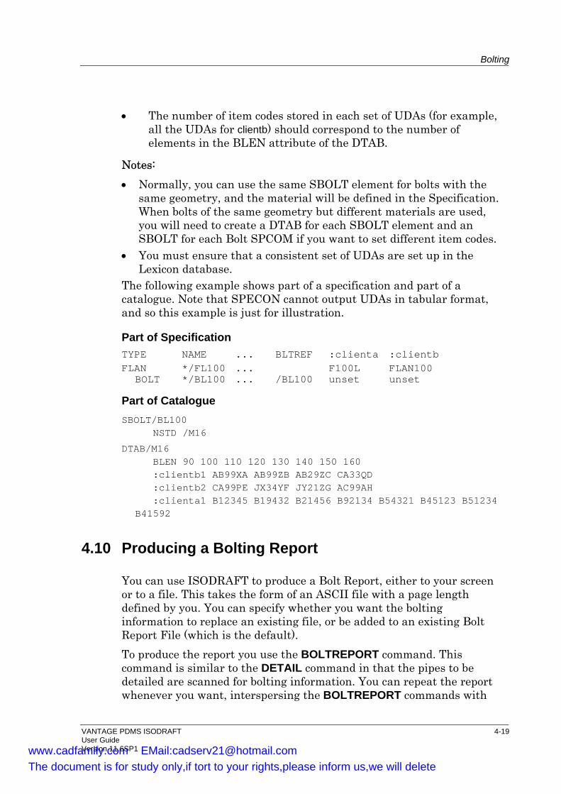
Bolting
• The number of item codes stored in each set of UDAs (for example, all the UDAs for clientb) should correspond to the number of elements in the BLEN attribute of the DTAB.
Notes: • Normally, you can use the same SBOLT element for bolts with the
same geometry, and the material will be defined in the Specification. When bolts of the same geometry but different materials are used, you will need to create a DTAB for each SBOLT element and an SBOLT for each Bolt SPCOM if you want to set different item codes.
• You must ensure that a consistent set of UDAs are set up in the Lexicon database.
The following example shows part of a specification and part of a catalogue. Note that SPECON cannot output UDAs in tabular format, and so this example is just for illustration.
Part of Specification TYPE NAME ... BLTREF :clienta : clientb FLAN */FL100 ... F100L FLAN100
BOLT */BL100 ... /BL100 unset unset
Part of Catalogue SBOLT/BL100
NSTD /M16
DTAB/M16 BLEN 90 100 110 120 130 140 150 160 :clientb1 AB99XA AB99ZB AB29ZC CA33QD :clientb2 CA99PE JX34YF JY21ZG AC99AH :clienta1 B12345 B19432 B21456 B92134 B54321 B45123 B51234 B41592
4.10 Producing a Bolting Report
You can use ISODRAFT to produce a Bolt Report, either to your screen or to a file. This takes the form of an ASCII file with a page length defined by you. You can specify whether you want the bolting information to replace an existing file, or be added to an existing Bolt Report File (which is the default). To produce the report you use the BOLTREPORT command. This command is similar to the DETAIL command in that the pipes to be detailed are scanned for bolting information. You can repeat the report whenever you want, interspersing the BOLTREPORT commands with
VANTAGE PDMS ISODRAFT 4-19 User Guide Version 11.6SP1 www.cadfamily.com EMail:[email protected]
The document is for study only,if tort to your rights,please inform us,we will delete
Bolting
DETAIL and CHECK commands as necessary. You will experience the same system checks when producing a bolt report as for detailing, but here only diagnostic information relevant to bolting will be produced. Therefore, you do not have to make sure that all piping geometry is correct before producing a bolt report. Note, however, that it is important to have the piping’s connectivity correct before producing a bolt report to make sure that all pipes are scanned properly. You can include positional information in the report. This will give you the centreline position of either associated flange in the coordinate system (as currently defined by the AXES command). The format of the positional information will be determined by the UNITS command. For further information see the Command Reference section in the VANTAGE PDMS ISODRAFT Reference Manual
4.11 Summary of Commands
The following commands were described in this chapter:
BOLTFILE Specifies the name of the bolt report file, produced using the BOLTREPORT command.
BOLTING Specifies where and how the bolt lengths are to be shown in the material list.
BOLTREPORT Allows you to output a report on the bolting containing identical information to that displayed in the material list.
4-20 VANTAGE PDMS ISODRAFT User Guide Version 11.6SP1 www.cadfamily.com EMail:[email protected]
The document is for study only,if tort to your rights,please inform us,we will delete
5 Design Requirements
This chapter describes how the pipework should have been designed so that ISODRAFT can produce the correct output.
5.1 Using the SPOOLER Module
The SPOOLER module allows you to: • Define the contents of the spool drawings, independent of the PDMS
pipe and branch hierarchy; • Add spool breaks to the design model, interactively; • Create numbering data for welds, pulled bends, parts, spools, and
joints. A Spool Drawing (SPLDRG) in SPOOLER normally forms a single isometric in ISODRAFT (although it may be plotted over a number of sheets). Each SPLDRG contains a number of Spools (fabricated assemblies) and Fields (erection parts) connected as a continuous piping network. The spooling data is defined in the Fabrication database, from where it is cross-referenced to the Design database. You define your spool drawing by selecting pipes and components that form a logical interconnected network, from the graphical display. Spools and Fields are automatically set where changes in the SHOP flag status occur. You can also change the SHOP flag on a component; force a Spool Break between two components; and add additional field welds, either on a component p-point or in a length of tube, to further split up the piping network. To provide even greater control, you can also set the SFLimit (spool/field limit) attribute on the SPLDRG to BRAN, PIPE, ZONE, SITE or WORLD (the default). This will force a spool break at any change of element at the specified hierarchic level; for example, at every change to a new Pipe. Once all the elements have been added to your spool drawing you can automatically number the spools, parts, welds, pulled bends and joints. These numbers can be easily updated if you make changes to your spool drawing or the design is changed. Once you have defined and numbered your spool drawings they can be plotted using ISODRAFT. Normally one spool drawing is shown on an
VANTAGE PDMS ISODRAFT 5-1 User Guide Version 11.6SP1 www.cadfamily.com EMail:[email protected]
The document is for study only,if tort to your rights,please inform us,we will delete
Design Requirements
isometric. Alternatively, you can produce isometrics showing either a single spool or a network of spool drawings. Further instructions on using SPOOLER can be found in the SPOOLER User Guide (which also contains a tutorial) and the on-line help file in the SPOOLER module.
5.1.1 Numbering in Spool Drawing Isometrics
SPOOLER can automatically create numbering for spools, parts, welds, non-welded joints and pulled bends. These numbers are stored in the database and can be output on the isometrics by enabling the required commands.
Spools SPOOLNumbers FROMDB
Parts MATEriallist PARTNumbers FROMDB
Welds WELDNumbers FROMDB
Joints JOINTNumbers ON
Pulled bends PBENDNumbers ON
5.2 Attachment Point Elements
ISODRAFT uses attachment point elements in the Design database, known as ATTAs. These are used to allow forces, moments, etc. to be applied to a Branch during pipe stressing, to show the location of support points, and to attach comments, flow arrows, etc. to the pipes on isometric plots. The different types of ATTA are defined by the setting of the ATTY attribute. The ATTY settings and other information for different types of ATTA are given below.
Support ATTAs are used to mark the position of a support on the pipe. There are three types of support ATTA:
•
a) ATTY type Unset, is the default type of support ATTA. They are used to mark the position of a support on the pipe. They should be positioned on the centreline of the pipe. If they are not: • Data consistency checking will generate an error message,
unless ATTACHECK OFF is set, in which case no check is made for correct orientation and position of the ATTA.
If the ATTA is within tube, it will be shown at the p-leave of the previous component or at the head of the branch. This
5-2 VANTAGE PDMS ISODRAFT User Guide Version 11.6SP1 www.cadfamily.com EMail:[email protected]
The document is for study only,if tort to your rights,please inform us,we will delete
Design Requirements
can cause the dimensioning of another Support ATTA further down the pipe to be omitted.
• To position the ATTA within the previous component, connect it in list order after the component, then explicitly set its position, or move it BY the required distance along the direction of P-arrive. Note that, in this case, data consistency checking will generate an error message unless ATTACHECK OFF is set.
For elbows and bends, ATTAs can be positioned on projected centrelines, i.e. at the intersection of centrelines.
Note: Supports on tube are shown with a symbol, but supports on components are not.
b) ATTY type Hang ATTAs are used in the Hangers & Supports application to indicate where a hanger type support will be attached to a pipe or component. They operate in exactly the same way as ATTY type Unset ATTAs.
c) ATTY type Weld ATTAs are also used in the Hangers & Supports application. This type of ATTA is used to position the plotted ATTA symbol a fixed distance inside the previous component (e.g. at the P0 of an ELBO component), rather than moving the ATTA to that point as you have to do with ATTY types Unset and Hang.
It is accomplished by the ATTA having a P3 point, which is a set distance in the arrive direction from P1/P2. The distance between P1/P2 and P3 must be set in the catalogue for each ATTA of this type, which is then used with the same component (e.g. ELBO). The symbol for this ATTA is automatically plotted at its P3 point.
Inserting the ATTA directly after the previous component ensures the ATTA symbol is plotted at the correct point inside that component.
• Comment ATTAs are used to add a drawing note with leader line to a position on a pipe, typically to add a floor penetration note. They have ATTY set to CCCC. If this point is not already dimensioned, for example, if it lies in the tube, additional dimensions to the ATTA position will be output. Comment ATTAs should lie on the centreline of the pipe. To position the ATTA within the previous component, connect it in list order after the component, then explicitly set its position, or move it BY the required distance along the direction of p-arrive. Note that, in
VANTAGE PDMS ISODRAFT 5-3 User Guide Version 11.6SP1 www.cadfamily.com EMail:[email protected]
The document is for study only,if tort to your rights,please inform us,we will delete

Design Requirements
this case, data consistency checking will generate an error message unless ATTACHECK OFF is set.
•
•
•
•
•
Non-dimensional Comment ATTAs are used to add a drawing note with leader line to a position on a pipe; for example, to add a paint colour note. They have ATTY set to CCNN. This type of ATTA will not be dimensioned.
Flow ATTAs are used to position inline flow arrows in tube. They have ATTY set to FLOW. The arrow is not dimensioned, but it is positioned on the tube in proportion to its 3D position. The flow is from head to tail if the FLOW of the branch is the default forwards direction, or tail to head if the FLOW of the branch is backwards. Note that you must use the FLOWARROWS INLINE command for flow arrows to be plotted for tube.
Split ATTAs for a normal isometric are used to set the point at which an isometric should be split onto the next sheet. They have ATTY set to XXXX. ISODRAFT sometimes repositions split points if a more logical point is close. For example, consider a Tee with a Flange welded to P3, and a Gasket and a Valve connected to the Flange. If a Split ATTA is positioned between the Tee and the Flange, ISODRAFT will split the pipe at the natural break formed by the Flange. Normal Split ATTAs are ignored for system isometrics and equipment trim isometrics.
Split ATTAs for system isometrics have ATTY set to SSSS. This type of ATTA is used to set the point at which a system isometric or equipment trim isometric should be split onto the next sheet. The same considerations as for normal isometric split ATTAs apply.
Insulation symbol ATTAs have ATTY set to INPP (insulation personnel protection). This ATTA type is used to set the start and stop points of insulation on the isometric. The insulation specification note will be shown at the start point of the insulation, but not at the end (to avoid duplicating information).
5-4 VANTAGE PDMS ISODRAFT User Guide Version 11.6SP1 www.cadfamily.com EMail:[email protected]
The document is for study only,if tort to your rights,please inform us,we will delete

Design Requirements
5.3 Reference Dimensions
If you have set up reference dimensions in the Design database, you can display them in ISODRAFT. To define a reference dimension, you must specify: • A reference datum (see Section 5.3.1). • A point on a Pipe which you want to dimension (see Section 5.3.2). The dimensions will be drawn from the reference datum to the point on the Pipe. Note: Reference dimensions do not affect normal dimensioning. Also,
they can be switched on and off independently of other types of dimensions. See the REFDIMENSIONS command.
5.3.1 Setting up a Reference Datum
For an element to be used as a reference datum, it must have: • An origin. • An SKEY attribute, or a parent with an SKEY attribute. The elements you can set up as reference datums are: • Datums; • Equipment; • Equipment and structural primitives such as boxes; • Sections; • Piping components; • Point elements, if they have a parent with an SKEY attribute.
VANTAGE PDMS ISODRAFT 5-5 User Guide Version 11.6SP1 www.cadfamily.com EMail:[email protected]
The document is for study only,if tort to your rights,please inform us,we will delete

Design Requirements
SKEY Attributes Elements used to define reference datums must have an SKEY attribute, or a parent with an SKEY attribute (but note that the parent element need not be the immediate owner of the element). If the element does not have an SKEY, and no parent has an SKEY, miscellaneous SKEY types (see below) will be used. Elements with SKEY attributes are:
Datums Equipment Pipes Structures Substructures Drawings Frameworks Subframeworks
Different SKEY types have different ATEXTs associated with them, as shown in the following table.
SKEY Type Item Type ATEXT Default text HST* Horizontal steelwork
element 460 BEAM $?
VST* Vertical steelwork element
461 COLUMN $?
BLD* Building 462 ? $BUILDING CL
EQU* Equipment item 463 CL EQUIPMENT $?
PIP* Piping component 464 CL PIPELINE $?
FLR* Floor level 465 ? $FLOOR LEVEL
WAL* Wall 466 ? $WALL
GRD* Grid line 467 GRID LINE $?
XXX* Miscellaneous 468 ?
In SKEY Types above, the symbol * represents any character. In Default texts, $ is replaced by a new line and ? is replaced by the name of the element. If the element does not have a name, ISODRAFT looks up the hierarchy until it finds a parent with a name, and then uses that parent’s name. If the reference element is a Datum element, it will have an STEXT attribute. You can set this attribute to any identification text you want. If
5-6 VANTAGE PDMS ISODRAFT User Guide Version 11.6SP1 www.cadfamily.com EMail:[email protected]
The document is for study only,if tort to your rights,please inform us,we will delete

Design Requirements
you do this, the text you enter will be used instead of the name. If you leave STEXT unset, the Datum name will be used. You should set the SKEY text to the SKEY type you require. Note that you can also redefine the text in the ATEXT element using the ATEXT command. For example: Pipe PIPE7-1 has an SKEY type VSTC. Associated with the pipe is ATEXT 464, with default text CL PIPELINE $?. The following text will appear on the isometric (see Figure 5-1):
CL PIPELINE PIPE7-1
Figure 5-1 also shows a reference to a Datum, which has its STEXT element set to Zero Elevation.
VANTAGE PDMS ISODRAFT 5-7 User Guide Version 11.6SP1 www.cadfamily.com EMail:[email protected]
The document is for study only,if tort to your rights,please inform us,we will delete
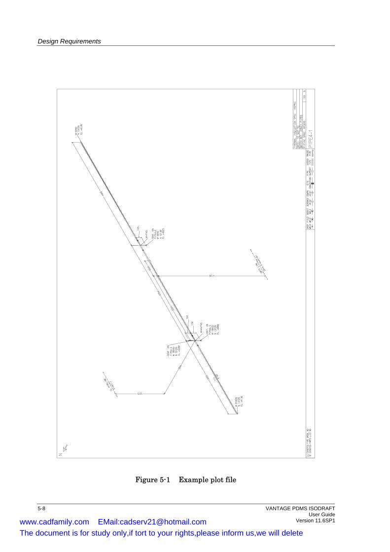
Design Requirements
Figure 5-1 Example plot file
5-8 VANTAGE PDMS ISODRAFT User Guide Version 11.6SP1 www.cadfamily.com EMail:[email protected]
The document is for study only,if tort to your rights,please inform us,we will delete
Design Requirements
Origins and Centrelines On the isometric, a centreline is drawn through the origin of the reference element. The reference dimension will be drawn from the centreline of the reference element. The centreline will normally be the Z-direction of the element, as defined by its orientation. • For Piping components the p-leave will be used. • For Sections the p-line direction will be used. • For Points, the direction of the centreline will be to the next Point in
the list. For the last Point in the list, the direction from the previous Point will be used. If there are no other Points, the direction will be the Z-direction of the Point’s owner.
5.3.2 Setting up a Reference Dimension
The point on the Pipe can be any of the following: • The origin (P0) of an Elbow, Tee, Bend, Cross or OLET. • The origin of a Support or Comment ATTA. • The position of the Head or Tail of a Branch. Note: 180 degree bends cannot be used for reference dimensions.
Piping Components and ATTAs A reference dimension is set up by setting the DMTYPE and DMFARRAY attributes of the piping component or ATTA. Support ATTAs and dimensioned or non-dimensioned Comment ATTAs can be used to create reference dimensions for points on tube. Split ATTAs and Flow ATTAs cannot be used. DMTYPE is a word array attribute. It defines which component of the reference dimension is plotted. It can be set to one or two of the following:
EAST NORT ELEV or POS for a 3D dimension
Figure 5-1 shows one reference dimension to a piping component with POS specified, and one reference dimension to a Datum, with ELEV specified. DMFARRAY is a reference array attribute. It is used to set the names of the reference elements.
VANTAGE PDMS ISODRAFT 5-9 User Guide Version 11.6SP1 www.cadfamily.com EMail:[email protected]
The document is for study only,if tort to your rights,please inform us,we will delete

Design Requirements
For example: DMTY NORT EAST DMFA /N.WALL /VESS2
produces two reference dimensions, one giving the distance North to the centreline of the element named /N.WALL and one giving the distance East to the centreline of the Equipment named /VESS2.
DMTY ELEV DMFA /SITE.BASE
produces a reference dimension to the centreline of the element /SITE BASE. The dimension will be to the centreline of the Reference element.
Branch Heads and Tails A reference dimension is set up by setting the HDMTYPE and HDMFARRAY attributes of the Head or TDMTYPE and TDMFARRAY attributes of the Tail. HDMTYPE and TDMTYPE are word array attributes. They can be set to one or two of the following:
EAST NORT ELEV or POS for a 3D dimension
HDMFARRAY and TDMFARRAY are reference array attributes used to set the names of the reference elements.
5.3.3 Errors
If you try to create a one-dimensional reference dimension which is parallel to the centreline of the reference datum element, the result will be as follows: • Dimensions to piping components or Sections will be omitted and an
error message will be given. • Dimensions to other elements will be created with a different
centreline direction, and a warning message given. • If you try to create a one-dimensional reference dimension where
the dimension line runs parallel to the pipe centreline, no dimensions will be plotted and you will be given an error message.
5-10 VANTAGE PDMS ISODRAFT User Guide Version 11.6SP1 www.cadfamily.com EMail:[email protected]
The document is for study only,if tort to your rights,please inform us,we will delete
Design Requirements
5.4 Additional Items for Material Take-off Items which are not part of the pipe (that is, items which are not dimensioned or shown graphically on the isometric) can be shown on the material list. Examples of this type of item are flange jacking screws, valve handwheel chains and extra blanks for testing. The additional items are associated with a normal piping component. The additional items are associated with a piping component by setting the reference array attribute MTOR of the piping component to point to up to 20 additional Specification references (SPREFs). The item codes and descriptions will be extracted as normal. The Detail and Material texts of the additional items are set as normal. A length or a quantity can be set for an additional item by setting the detail text element MTOL or MTOQ attributes, respectively. The description or quantity will appear in the Material list under Miscellaneous items.
5.5 Data Consistency Checking Before you process a pipeline using ISODRAFT, you should carry out a data consistency check on the pipeline in DESIGN or INTREPID. This is particularly important during batch mode operation.
5.6 Summary of Commands
The following commands were described in this chapter:
JOINTNUMBERS Puts the joint numbers created in SPOOLER on the isometric.
MATERIAL PARTNUMBERS FROMDB
Allows you to select whether to use the part numbering from the database.
PBENDNUMBERS Puts the pulled bend numbers created in SPOOLER on the isometric.
SPOOLNUMBERS FROMDB
Lets you specify whether to use the numbers created by SPOOLER or let ISODRAFT number the spools itself.
WELDNUMBERS FROMDB
Lets you decide whether to use the numbers created by SPOOLER or let ISODRAFT number the spools itself.
VANTAGE PDMS ISODRAFT 5-11 User Guide Version 11.6SP1 www.cadfamily.com EMail:[email protected]
The document is for study only,if tort to your rights,please inform us,we will delete

Design Requirements
5-12 VANTAGE PDMS ISODRAFT User Guide Version 11.6SP1 www.cadfamily.com EMail:[email protected]
The document is for study only,if tort to your rights,please inform us,we will delete
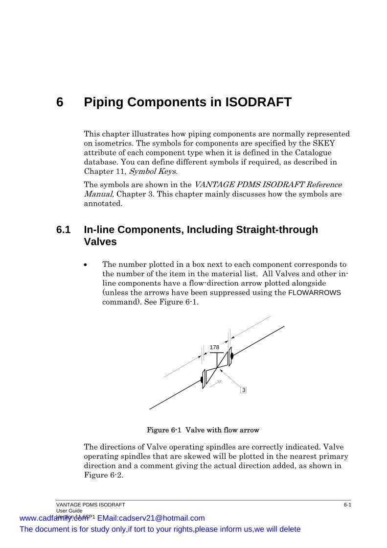
6 Piping Components in ISODRAFT
This chapter illustrates how piping components are normally represented on isometrics. The symbols for components are specified by the SKEY attribute of each component type when it is defined in the Catalogue database. You can define different symbols if required, as described in Chapter 11, Symbol Keys. The symbols are shown in the VANTAGE PDMS ISODRAFT Reference Manual, Chapter 3. This chapter mainly discusses how the symbols are annotated.
6.1 In-line Components, Including Straight-through Valves
• The number plotted in a box next to each component corresponds to the number of the item in the material list. All Valves and other in-line components have a flow-direction arrow plotted alongside (unless the arrows have been suppressed using the FLOWARROWS command). See Figure 6-1.
3
178
Figure 6-1 Valve with flow arrow
The directions of Valve operating spindles are correctly indicated. Valve operating spindles that are skewed will be plotted in the nearest primary direction and a comment giving the actual direction added, as shown in Figure 6-2.
VANTAGE PDMS ISODRAFT 6-1 User Guide Version 11.6SP1 www.cadfamily.com EMail:[email protected]
The document is for study only,if tort to your rights,please inform us,we will delete
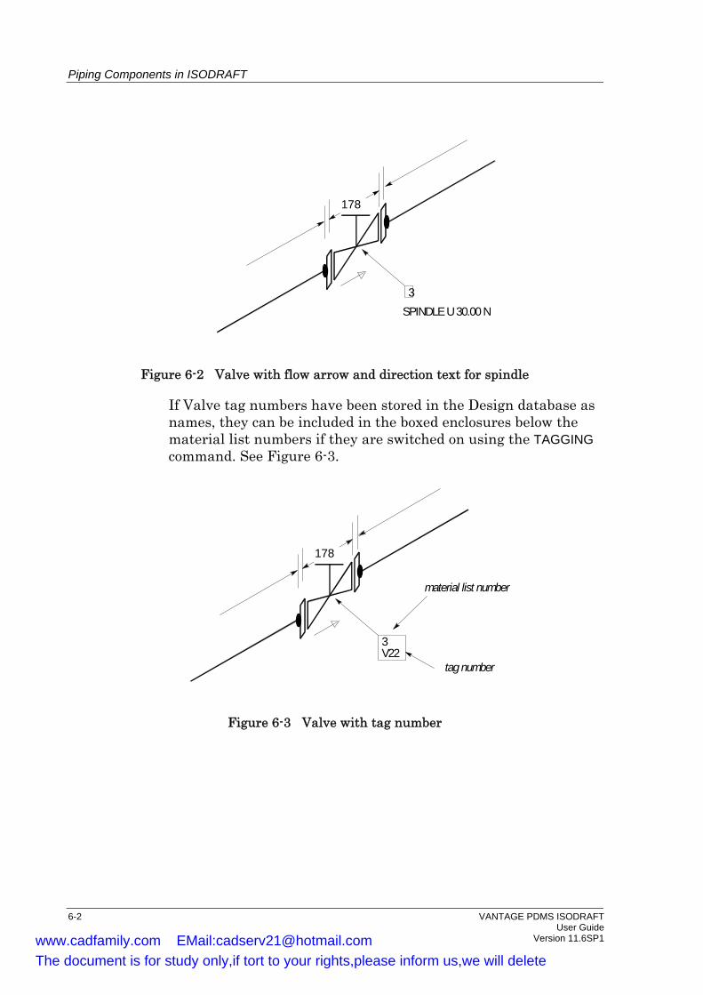
Piping Components in ISODRAFT
3SPINDLE U 30.00 N
178
Figure 6-2 Valve with flow arrow and direction text for spindle
If Valve tag numbers have been stored in the Design database as names, they can be included in the boxed enclosures below the material list numbers if they are switched on using the TAGGING command. See Figure 6-3.
3V22
material list number
tag number
178
Figure 6-3 Valve with tag number
6-2 VANTAGE PDMS ISODRAFT User Guide Version 11.6SP1 www.cadfamily.com EMail:[email protected]
The document is for study only,if tort to your rights,please inform us,we will delete

Piping Components in ISODRAFT
6.2 Angled, 3-Way, and 4-Way Valves
For angled, 3-way and 4-way Valves the dimension lines along valve body sections will not be plotted. The body dimensions will be shown with arrows pointing to the component. The figures will be followed by the units.
241 MM
3241 MM
Figure 6-4 Angled valve with dimensioning detail
6.3 Flanges
The material list numbers for the Flange, associated Gasket and Bolts will be plotted as shown in Figure 6-5.
F3 G8 B10
Figure 6-5 Material list numbers for flange, gasket and bolts
VANTAGE PDMS ISODRAFT 6-3 User Guide Version 11.6SP1 www.cadfamily.com EMail:[email protected]
The document is for study only,if tort to your rights,please inform us,we will delete
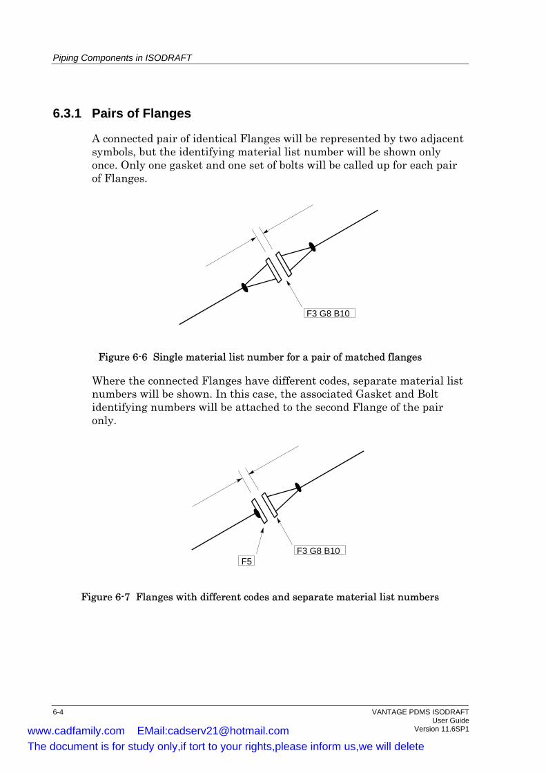
Piping Components in ISODRAFT
6.3.1 Pairs of Flanges
A connected pair of identical Flanges will be represented by two adjacent symbols, but the identifying material list number will be shown only once. Only one gasket and one set of bolts will be called up for each pair of Flanges.
F3 G8 B10
Figure 6-6 Single material list number for a pair of matched flanges
Where the connected Flanges have different codes, separate material list numbers will be shown. In this case, the associated Gasket and Bolt identifying numbers will be attached to the second Flange of the pair only.
F3 G8 B10 F5
Figure 6-7 Flanges with different codes and separate material list numbers
6-4 VANTAGE PDMS ISODRAFT User Guide Version 11.6SP1 www.cadfamily.com EMail:[email protected]
The document is for study only,if tort to your rights,please inform us,we will delete

Piping Components in ISODRAFT
6.3.2 Reducing Flanges
In addition to the normal material list numbers for the Flange and associated Gasket and Bolts, the primary and secondary sizes will be listed along with the message REDUCING FLANGE.
F7 G9 B11 F5
6 X 4 " NS REDUCING FLANGE
4 " NS
Figure 6-8 Additional information for a reducing flange
For offset reducing Flanges, the dimension and direction of the offset will also be shown.
F7 G9 B11 F5
6 X 4 " NS REDUCING FLANGE25 MM OFFSET DOWN
4 " NS
Figure 6-9 Additional information for an offset reducing flange
6.4 Wafer Fittings
Where in-line wafer fittings, such as ‘Butterfly Valves’, ‘Orifice Plates, etc., are incorporated between pairs of flanges, a single set of extra long bolts is required. The material list number for these bolts will be added
VANTAGE PDMS ISODRAFT 6-5 User Guide Version 11.6SP1 www.cadfamily.com EMail:[email protected]
The document is for study only,if tort to your rights,please inform us,we will delete

Piping Components in ISODRAFT
to the Flange and Gasket numbers for the second flange of the pair. The first Flange will also have the Flange and Gasket serial numbers attached, since two Gaskets are necessary in total for such an assembly.
F2 G3 B4
F2G3
740
Figure 6-10 Bolt information for flanges enclosing wafer fittings
6.5 Tees and Crosses
TEEs, OLETs and set-on Tees (stub ins) are represented by different symbols. The primary and secondary bore sizes of the tee are indicated by a message linked to the tee intersection point. The branch pipe size is plotted against the third pipe leg.
3
6 X 3 " NS
4
6 X 1 " NS
Figure 6-11 Presentation of TEEs and OLETs
A reinforced set-on Tee will have the text REINFORCED added to supplement the plotted shape. See Figure 6-12.
6-6 VANTAGE PDMS ISODRAFT User Guide Version 11.6SP1 www.cadfamily.com EMail:[email protected]
The document is for study only,if tort to your rights,please inform us,we will delete

Piping Components in ISODRAFT
6 X 3" NSREINFORCED
Figure 6-12 Extra text for a reinforced set-on TEE
6.5.1 Crosses
Crosses are shown like Tees except that the message specifying the main and branch sizes is extended to show the second branch size.
6 X 3 X 3" NS
3503" NS
Figure 6-13 Additional information for crosses
VANTAGE PDMS ISODRAFT 6-7 User Guide Version 11.6SP1 www.cadfamily.com EMail:[email protected]
The document is for study only,if tort to your rights,please inform us,we will delete

Piping Components in ISODRAFT
6.6 Reducers
For both eccentric and concentric Reducers, the large (primary) and small (secondary) diameters will be shown in a message of the format LxS NS, where Large and Small are the nominal bore sizes. An eccentric Reducer has its symbol drawn so as to show the orientation of its flat side, with the offset dimension listed under the size message.
3
6 X 3 " NS
3 " NS
140
3
6 X 3 " NS38 MM OFFSET
3 " NS
140
a. Concentric b. Eccentric
Figure 6-14 The annotation of reducers
Text information about the direction of the flat side of eccentric Reducers is not normally plotted, but you can plot it using the alternative text facility. See the ATEXT command, and ATEXTs 243 and 283. For example, the text FLAT DOWN can be output by this method.
6.6.1 Reducers With a Branch Connection
These can be based upon either a concentric or eccentric body. Due to the difficulty of drawing an unambiguous representation of this type of component, all information relevant to the Branch will be given in a message line as shown in Figure 6-15. The message 1”NS refers to the branch bore, while the 100 (mm) dimension is an overall one from the connection point of the reducer to the flange face. The dimension along the body of the Reducer to the branch will not be indicated and the branch pipe will be drawn at the mid point of the reducer.
6-8 VANTAGE PDMS ISODRAFT User Guide Version 11.6SP1 www.cadfamily.com EMail:[email protected]
The document is for study only,if tort to your rights,please inform us,we will delete
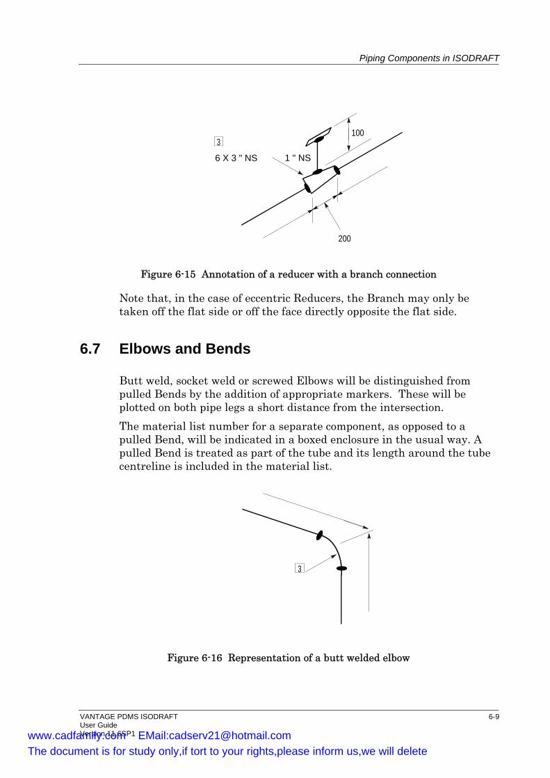
Piping Components in ISODRAFT
1 " NS
200
3
6 X 3 " NS
100
Figure 6-15 Annotation of a reducer with a branch connection
Note that, in the case of eccentric Reducers, the Branch may only be taken off the flat side or off the face directly opposite the flat side.
6.7 Elbows and Bends
Butt weld, socket weld or screwed Elbows will be distinguished from pulled Bends by the addition of appropriate markers. These will be plotted on both pipe legs a short distance from the intersection. The material list number for a separate component, as opposed to a pulled Bend, will be indicated in a boxed enclosure in the usual way. A pulled Bend is treated as part of the tube and its length around the tube centreline is included in the material list.
3
Figure 6-16 Representation of a butt welded elbow
VANTAGE PDMS ISODRAFT 6-9 User Guide Version 11.6SP1 www.cadfamily.com EMail:[email protected]
The document is for study only,if tort to your rights,please inform us,we will delete

Piping Components in ISODRAFT
Right-angled Bends and Elbows are not marked as such, since the angle is usually obvious. All other bend angles are identified by a message giving the acute angle in degrees, linked to the intersection point of the legs. See Figure 6-17.
385°
Figure 6-17 Identification of an acute angle
6.8 Pipe Ends and their Connections
Pipe ends will normally have specific text messages plotted next to them under the following circumstances: • At the start of a Pipe; • At the end of any type of off-line Branch; • At the end of a Pipe. These messages show how the Pipe is continued from that point onwards, or any special Pipe end condition that may be required, as shown in the following examples. Full E-W, N-S and elevation (EL) coordinates will be listed for the start and finish of each Pipe. They will also be listed at the end of every Tee off-line branch; in other words, at all connection points. Where a Pipe is connected to another Pipe, the coordinates will be preceded by a CONT. ON message. In Figure 6-18, a Branch of PIPE-36A is the HREF or TREF of the Pipe shown.
6-10 VANTAGE PDMS ISODRAFT User Guide Version 11.6SP1 www.cadfamily.com EMail:[email protected]
The document is for study only,if tort to your rights,please inform us,we will delete
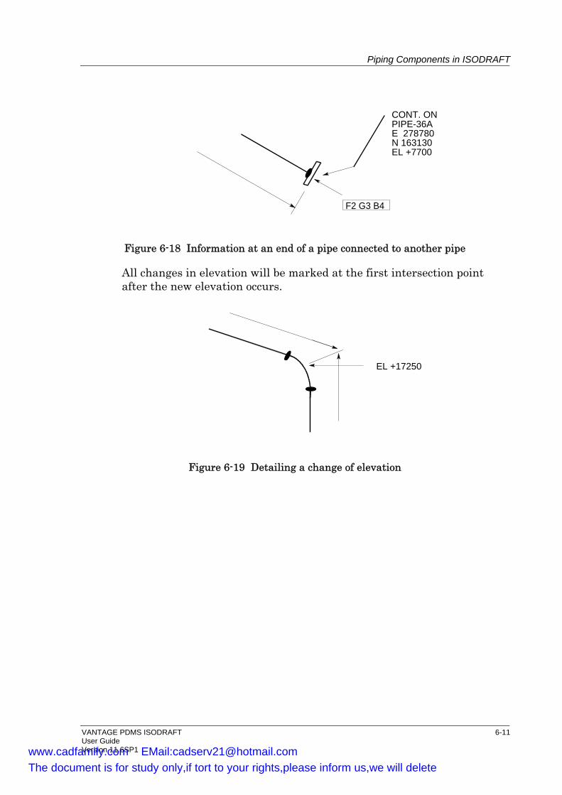
Piping Components in ISODRAFT
F2 G3 B4
CONT. ONPIPE-36AE 278780N 163130EL +7700
Figure 6-18 Information at an end of a pipe connected to another pipe
All changes in elevation will be marked at the first intersection point after the new elevation occurs.
EL +17250
Figure 6-19 Detailing a change of elevation
VANTAGE PDMS ISODRAFT 6-11 User Guide Version 11.6SP1 www.cadfamily.com EMail:[email protected]
The document is for study only,if tort to your rights,please inform us,we will delete

Piping Components in ISODRAFT
6.8.1 Connection To Equipment Nozzle
The pipe end will carry the message CONN. TO followed by the relevant identification.
CONT. TOC12/N8E 278780N 163130EL +77003 " NS
Figure 6-20 Detail of connection of a Pipe to a Nozzle. C12/N8 is the HREF or TREF identifier of the Branch.
6.8.2 Continuation on Another Drawing
The Pipe end will carry the message CONT. ON or CONT. FROM followed by the identification of the other drawing.
CONT. FROMDRG.1
3 " NS
820
Figure 6-21 Detail of continuation from another drawing
6-12 VANTAGE PDMS ISODRAFT User Guide Version 11.6SP1 www.cadfamily.com EMail:[email protected]
The document is for study only,if tort to your rights,please inform us,we will delete

Piping Components in ISODRAFT
6.8.3 Special Pipe End Conditions
An appropriate message will define the special condition, as illustrated in Figure 6-22.
SCREWED ENDE 276720N 161848EL + 5000
VENTE 276720N 161848EL + 5000
DRAINE 276720N 161848EL + 5000
HCON/TCON = SCRD VENT DRAN(Screwed) (Drain)
Figure 6-22 Labelling of special Pipe end conditions
6.8.4 Open and Closed Ends
Where a Branch end (HCON or TCON) is deliberately designated OPEN or CLOS it will not have any specific text marking it as such on the isometric drawing. Only the coordinates of the Pipe end will be plotted. The alternative text facility (see the ATEXT command) can be used to add extra messages to OPEN or CLOS ends if required.
E 276720N 161848EL + 5000
Figure 6-23 Coordinate marking at open and closed ends
VANTAGE PDMS ISODRAFT 6-13 User Guide Version 11.6SP1 www.cadfamily.com EMail:[email protected]
The document is for study only,if tort to your rights,please inform us,we will delete
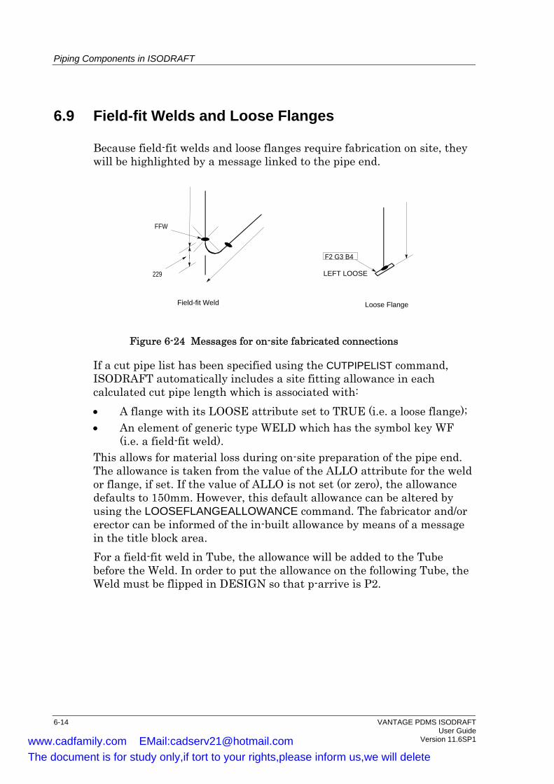
Piping Components in ISODRAFT
6.9 Field-fit Welds and Loose Flanges
Because field-fit welds and loose flanges require fabrication on site, they will be highlighted by a message linked to the pipe end.
F2 G3 B4
LEFT LOOSE
Loose Flange
FFW
229
Field-fit Weld
Figure 6-24 Messages for on-site fabricated connections
If a cut pipe list has been specified using the CUTPIPELIST command, ISODRAFT automatically includes a site fitting allowance in each calculated cut pipe length which is associated with: • A flange with its LOOSE attribute set to TRUE (i.e. a loose flange); • An element of generic type WELD which has the symbol key WF
(i.e. a field-fit weld). This allows for material loss during on-site preparation of the pipe end. The allowance is taken from the value of the ALLO attribute for the weld or flange, if set. If the value of ALLO is not set (or zero), the allowance defaults to 150mm. However, this default allowance can be altered by using the LOOSEFLANGEALLOWANCE command. The fabricator and/or erector can be informed of the in-built allowance by means of a message in the title block area. For a field-fit weld in Tube, the allowance will be added to the Tube before the Weld. In order to put the allowance on the following Tube, the Weld must be flipped in DESIGN so that p-arrive is P2.
6-14 VANTAGE PDMS ISODRAFT User Guide Version 11.6SP1 www.cadfamily.com EMail:[email protected]
The document is for study only,if tort to your rights,please inform us,we will delete
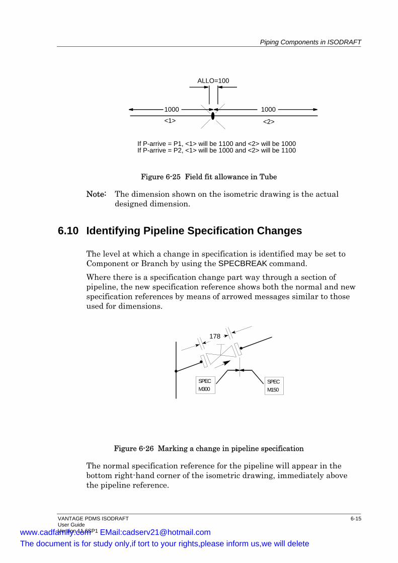
Piping Components in ISODRAFT
If P-arrive = P1, <1> will be 1100 and <2> will be 1000If P-arrive = P2, <1> will be 1000 and <2> will be 1100
1000 1000
ALLO=100
<1> <2>
Figure 6-25 Field fit allowance in Tube
Note: The dimension shown on the isometric drawing is the actual designed dimension.
6.10 Identifying Pipeline Specification Changes
The level at which a change in specification is identified may be set to Component or Branch by using the SPECBREAK command. Where there is a specification change part way through a section of pipeline, the new specification reference shows both the normal and new specification references by means of arrowed messages similar to those used for dimensions.
SPECM300
SPECM150
178
Figure 6-26 Marking a change in pipeline specification
The normal specification reference for the pipeline will appear in the bottom right-hand corner of the isometric drawing, immediately above the pipeline reference.
VANTAGE PDMS ISODRAFT 6-15 User Guide Version 11.6SP1 www.cadfamily.com EMail:[email protected]
The document is for study only,if tort to your rights,please inform us,we will delete
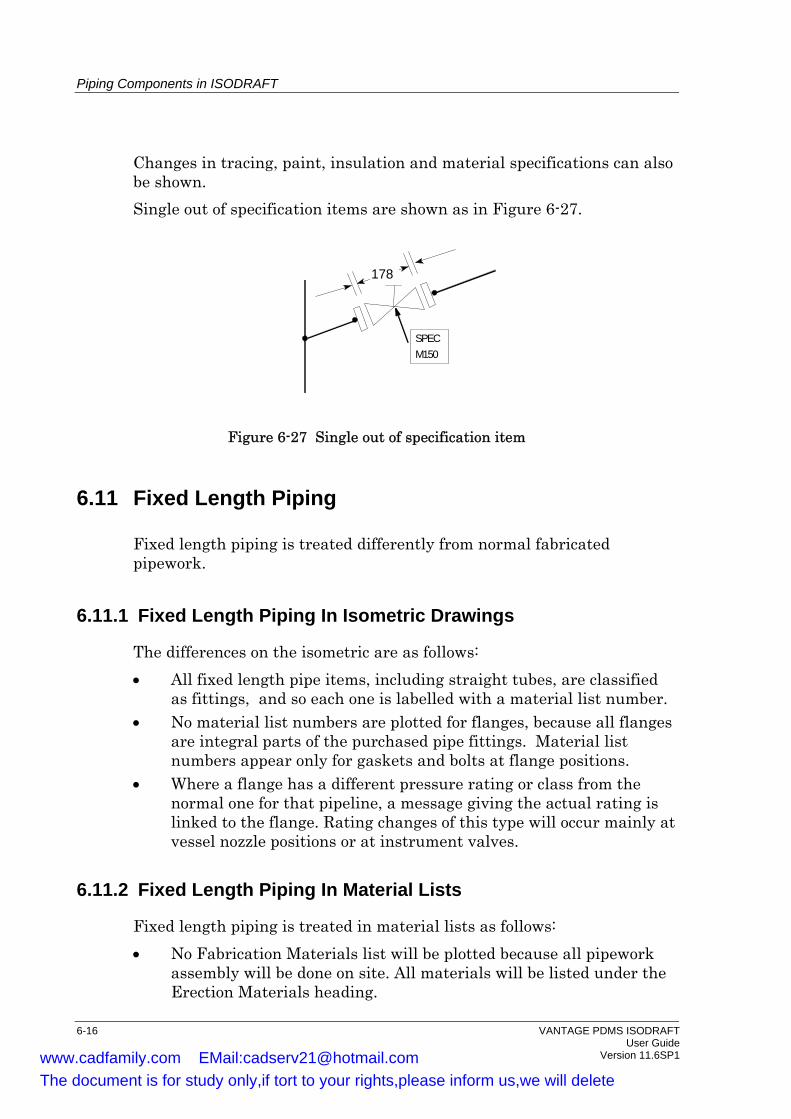
Piping Components in ISODRAFT
Changes in tracing, paint, insulation and material specifications can also be shown. Single out of specification items are shown as in Figure 6-27.
SPECM150
178
Figure 6-27 Single out of specification item
6.11 Fixed Length Piping
Fixed length piping is treated differently from normal fabricated pipework.
6.11.1 Fixed Length Piping In Isometric Drawings
The differences on the isometric are as follows: • All fixed length pipe items, including straight tubes, are classified
as fittings, and so each one is labelled with a material list number. • No material list numbers are plotted for flanges, because all flanges
are integral parts of the purchased pipe fittings. Material list numbers appear only for gaskets and bolts at flange positions.
• Where a flange has a different pressure rating or class from the normal one for that pipeline, a message giving the actual rating is linked to the flange. Rating changes of this type will occur mainly at vessel nozzle positions or at instrument valves.
6.11.2 Fixed Length Piping In Material Lists
Fixed length piping is treated in material lists as follows: • No Fabrication Materials list will be plotted because all pipework
assembly will be done on site. All materials will be listed under the Erection Materials heading.
6-16 VANTAGE PDMS ISODRAFT User Guide Version 11.6SP1 www.cadfamily.com EMail:[email protected]
The document is for study only,if tort to your rights,please inform us,we will delete
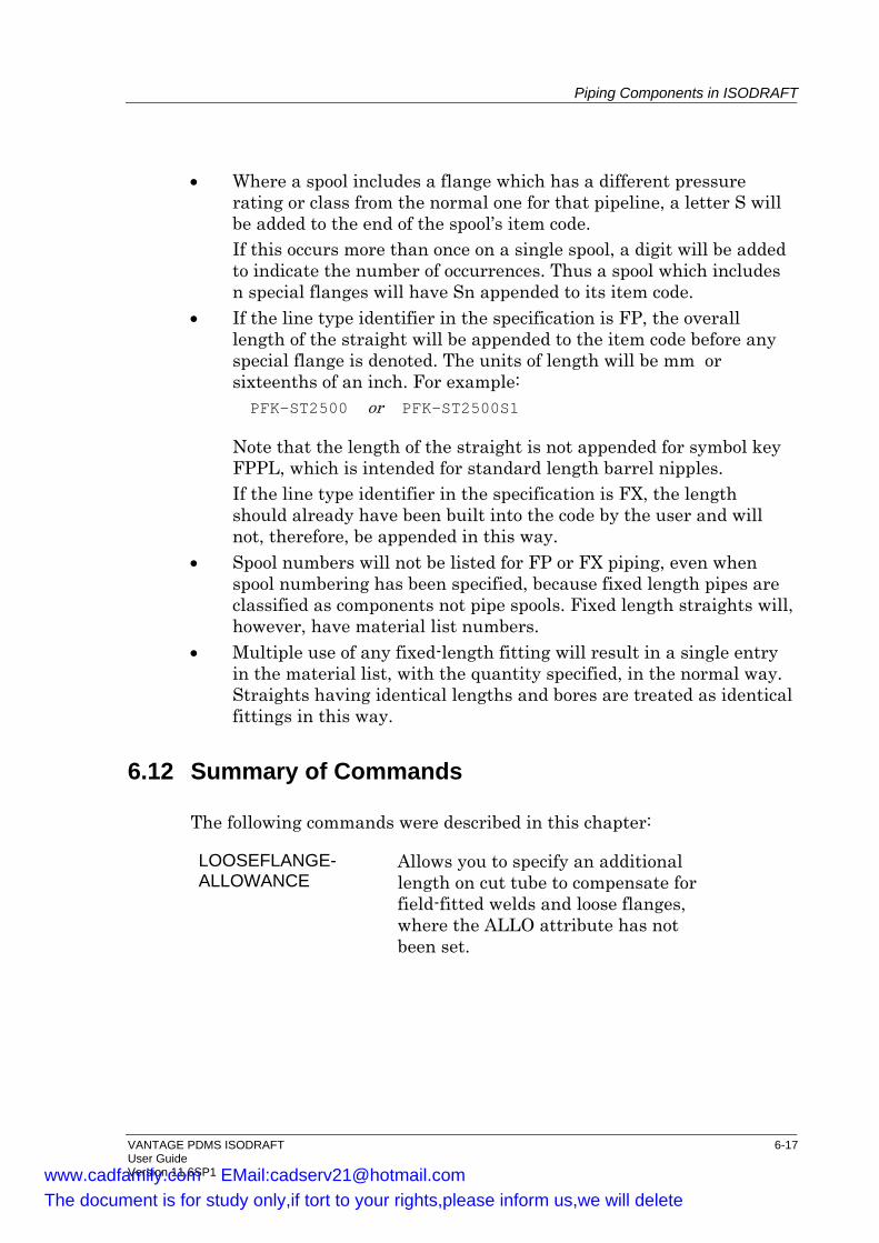
Piping Components in ISODRAFT
• Where a spool includes a flange which has a different pressure rating or class from the normal one for that pipeline, a letter S will be added to the end of the spool’s item code.
If this occurs more than once on a single spool, a digit will be added to indicate the number of occurrences. Thus a spool which includes n special flanges will have Sn appended to its item code.
• If the line type identifier in the specification is FP, the overall length of the straight will be appended to the item code before any special flange is denoted. The units of length will be mm or sixteenths of an inch. For example: PFK-ST2500 or PFK-ST2500S1
Note that the length of the straight is not appended for symbol key FPPL, which is intended for standard length barrel nipples.
If the line type identifier in the specification is FX, the length should already have been built into the code by the user and will not, therefore, be appended in this way.
• Spool numbers will not be listed for FP or FX piping, even when spool numbering has been specified, because fixed length pipes are classified as components not pipe spools. Fixed length straights will, however, have material list numbers.
• Multiple use of any fixed-length fitting will result in a single entry in the material list, with the quantity specified, in the normal way. Straights having identical lengths and bores are treated as identical fittings in this way.
6.12 Summary of Commands
The following commands were described in this chapter:
LOOSEFLANGE-ALLOWANCE
Allows you to specify an additional length on cut tube to compensate for field-fitted welds and loose flanges, where the ALLO attribute has not been set.
VANTAGE PDMS ISODRAFT 6-17 User Guide Version 11.6SP1 www.cadfamily.com EMail:[email protected]
The document is for study only,if tort to your rights,please inform us,we will delete

Piping Components in ISODRAFT
6-18 VANTAGE PDMS ISODRAFT User Guide Version 11.6SP1 www.cadfamily.com EMail:[email protected]
The document is for study only,if tort to your rights,please inform us,we will delete
7 Customising the Drawing Sheet
This chapter describes how you can customise the layout and content of an ISODRAFT drawing sheet. The default layout is shown in Figure 2-1.
7.1 Isometric Types
The ISOTYPE command specifies whether the information in the drawing is intended for: • In-shop fabrication; • On-site erection; • Both in-shop fabrication and on-site erection; • In-shop fabrication of pipe spools (i.e. prefabricated sections of a
larger piping assembly); • Any of the isometric types can be produced with the drawing area
left blank. A list of cut pipe lengths can be included if required. See the CUTTINGLIST command.
7.2 Units
You can specify the units for options such as paper size, margin widths, and cutting allowances. The default units are taken from the Catalogue. They can be changed before the value is input by using one of the commands:
MILlimetre MM (a shorter form of the preceding option) FInch (i.e. feet and inches) INch
followed, in the same command line, by one of the options: BOres DIstances
to define the type of measurement to which the units are to apply. This sets the current units, which remain in force until reset.
VANTAGE PDMS ISODRAFT 7-1 User Guide Version 11.6SP1 www.cadfamily.com EMail:[email protected]
The document is for study only,if tort to your rights,please inform us,we will delete

Customising the Drawing Sheet
For example, a loose flange allowance could be specified in feet and inches by the command sequence:
FINCH DISTANCES LOOSE 1’6
Alternatively, values may be input together with their corresponding units regardless of the current unit settings. Thus the previous example could be replaced by the single command
LOOSE 1 FT 6 IN
without affecting the current unit specifications. The current units may be queried at any time by using the command
Query UNIts
Units for dimensions on the isometrics are specified by the UNITS command. They can be queried by the Q OUTPUT UNITS commands.
7.3 Sheet Size
7.3.1 The Designed Drawing Sheet Size
The overall size of the plotted sheet produced by ISODRAFT can be set to an ISO (International Standards Organisation) A-size, to an American standard size, or to specified dimensions. The selected paper size will be divided between the isometric area, the material list area, the title block area, the margins, and so on. The default paper size is A2. It is changed by using the SIZE command.
7.3.2 The Plotted Drawing Sheet Size
By default, the actual size of the plotted drawing sheet generated by ISODRAFT is the same as the designed sheet size. You can specify a plotted sheet smaller than the designed sheet by using the PLOTTINGSCALE command.
7.3.3 Margins On Drawing Sheets
You can set the top, bottom, left and right margins on the drawing sheet by using the MARGIN command. The default is a 5mm margin all round.
7-2 VANTAGE PDMS ISODRAFT User Guide Version 11.6SP1 www.cadfamily.com EMail:[email protected]
The document is for study only,if tort to your rights,please inform us,we will delete
Customising the Drawing Sheet
7.3.4 Blank Areas on the Drawing Sheet and Material list
An area along the bottom of the drawing area and Material list can be left blank by using the RESERVE command A reserved area can be used for standard notes (a company name etc.), or it can be filled by information on a pre-printed sheet using the UNDERLAYPLOT command, or filled by Dynamic Detail Areas (see Section 7.6).
7.4 Using a Plot File as a Backdrop
An ISODRAFT plot file can be superimposed on a plot file created in another PDMS module by using the UNDERLAYPLOTFILE command. Up to eight underlays can be specified. The underlay plot files must have the same sheet size as the ISODRAFT output.
7.5 Arranging Multiple Plots on the Paper
If you are sending multiple plots to a single file (see the FILE command), the plots will normally be arranged one after another along the length of the paper. If the paper is wide enough, you may want to arrange the isometrics so that several are plotted across the width of the sheet. You can control how the plots are arranged by using the STACKINGARRANGEMENT command.
7.6 Dynamic Detail Areas on the Drawing Sheet
You can include Dynamic Detail Area plot files on the isometric. These show details of particular items of interest; for example, they could be used to show details of: welded supports; drain and vent assemblies; reinforcement pads; complex manifolds; and so on. They can be produced in DRAFT or any other suitable 2D drawing program. All branch members and specification components possess a DPFN attribute, which can be set to hold a Detail Plot File Name. ISODRAFT can automatically pick up these plot files when detailing and place them on the isometric. The detail plot is output on the same drawing sheet as the component with which it is associated. Detail Area output is switched on using the POSItion DETAILPlots command. Up to 20 Detail Areas can be plotted on a single isometric.
VANTAGE PDMS ISODRAFT 7-3 User Guide Version 11.6SP1 www.cadfamily.com EMail:[email protected]
The document is for study only,if tort to your rights,please inform us,we will delete

Customising the Drawing Sheet
Detail plots may also include the parameterised values of system and user defined attributes (UDAs). The attributes shown can be defined using the PLOTDETAILDATA command. This allows you to select which attributes to show, the x and y coordinates relative to the origin of the plot file, the character height, and the angle at which the text is to be plotted. The different attribute types are displayed as follows: • Array type attributes are shown separated by a new line. • Reference attributes are expanded to give the full PDMS name. • Logical attributes are output as T(rue) or F(alse). • Position, orientation and direction attributes are separated by
spaces.
7.6.1 Positioning the Detail Plots
A blank area of the drawing sheet can be set aside for the detail plots, using the RESERVE command. This command allows you to reserve an area at either the bottom of the plotting area or of the material list area. The plots can then be positioned in this area using the POSItion DETAILPlots command, The POSItion DETAILPlots command requires you to specify the following additional information: • The start point coordinates (x and y) for the first plot. • The direction to line up further detail plots. • A stacking integer and direction, to stack the plots if the number of
plots exceeds the integer. Producing a matrix of parallel rows and columns.
Alternatively, a grid reference number may be specified for each detail plot, in the DPGRID attribute of the component. The plot will be positioned at the origin of the defined area of the drawing area. The drawing area is divided up into 9 sections (3 x 3 square) as shown in the following diagram.
7-4 VANTAGE PDMS ISODRAFT User Guide Version 11.6SP1 www.cadfamily.com EMail:[email protected]
The document is for study only,if tort to your rights,please inform us,we will delete
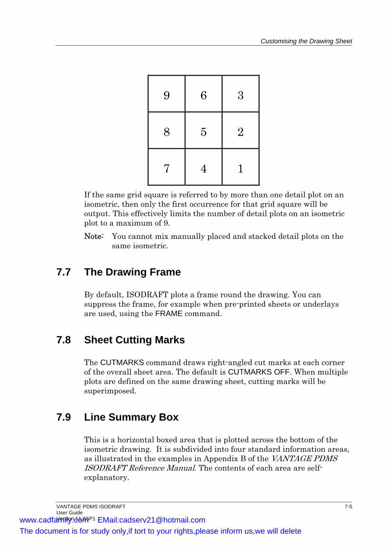
Customising the Drawing Sheet
9 6 3
8 5 2
7 4 1
If the same grid square is referred to by more than one detail plot on an isometric, then only the first occurrence for that grid square will be output. This effectively limits the number of detail plots on an isometric plot to a maximum of 9. Note: You cannot mix manually placed and stacked detail plots on the
same isometric.
7.7 The Drawing Frame
By default, ISODRAFT plots a frame round the drawing. You can suppress the frame, for example when pre-printed sheets or underlays are used, using the FRAME command.
7.8 Sheet Cutting Marks
The CUTMARKS command draws right-angled cut marks at each corner of the overall sheet area. The default is CUTMARKS OFF. When multiple plots are defined on the same drawing sheet, cutting marks will be superimposed.
7.9 Line Summary Box
This is a horizontal boxed area that is plotted across the bottom of the isometric drawing. It is subdivided into four standard information areas, as illustrated in the examples in Appendix B of the VANTAGE PDMS ISODRAFT Reference Manual. The contents of each area are self-explanatory.
VANTAGE PDMS ISODRAFT 7-5 User Guide Version 11.6SP1 www.cadfamily.com EMail:[email protected]
The document is for study only,if tort to your rights,please inform us,we will delete

Customising the Drawing Sheet
You can change or remove the contents of the four boxed areas using the ATEXT (alternative text) command.
7.10 The Title Block
7.10.1 Additional Title Block Text
You can customise the title block using the TITLEBLOCK command. You can add extra lines of text, and create boxes round them by using underscore and vertical bar characters.
7.10.2 Suppressing Title Block Text
You can suppress title block information by using the POSITION command to reposition title block text at 0,0.
7.10.3 Drawing Issue Numbering
When an isometric drawing is reissued after a change, the issue number of the drawing can be updated and plotted automatically by ISODRAFT. The issue number is taken from the REV attribute of the pipe being detailed. See the MARK REVISION command. When this facility is used, the issue number is shown in the title block in the bottom right-hand corner of the isometric (see Figure 7-1). The default text is ISS: n, where n is the issue number. This can be changed to REV: n or any other text by using the ATEXT (alternative text) command to change ATEXT 254.
ISS: 1
DRG NO1 OF 2
DATE: 24 JUL 87
PROJECT NO: VC12
BATCH REF: A16 /OG8 /CG14
PIPING SPEC: PS20
0-4201
Figure 7-1 Standard style of title block
7-6 VANTAGE PDMS ISODRAFT User Guide Version 11.6SP1 www.cadfamily.com EMail:[email protected]
The document is for study only,if tort to your rights,please inform us,we will delete

Customising the Drawing Sheet
7.10.4 Project Numbers on Drawings
The default is for no project number to be shown on the drawings. The project number can be included in the title block area on isometric drawing sheets by using the PROJECTNUMBER command. The project number shown on entry to the project can be plotted automatically, or a number can be added manually.
7.10.5 The Date Format
By default, the date is shown in UK format. It can be changed to European or American format, or switched off completely, using the DATE command.
7.11 Alternative Text
The four main areas on the isometric drawing all contain, by default, standard text generated by ISODRAFT. The areas are: • The isometric drawing area itself; • The title block in the lower right-hand corner; • The material list; • The line summary across the bottom. Examples: The FABRICATION MATERIALS heading on the material list. The CONN. TO and CONT. ON messages in the drawing area. The BATCH REF and PIPING SPEC labels in the title block area. Each text item is identified by a unique code number, known as its ATEXT (Alternative Text) number. The ATEXT command allows you to change the text characters associated with a particular ATEXT number, so that your specified text replaces the standard wording at the corresponding location on the drawing. You can also suppress the text by setting the ATEXT to null.
7.12 User-Positioned Text
All items of text used for the standard annotation of isometrics have default positions at which they are plotted on the drawings. Some of these annotations can be repositioned using the POSITION command. The POSITION command can also be used to position up to 100 pipe
VANTAGE PDMS ISODRAFT 7-7 User Guide Version 11.6SP1 www.cadfamily.com EMail:[email protected]
The document is for study only,if tort to your rights,please inform us,we will delete
Customising the Drawing Sheet
attributes such as the pipe’s name, owner, temperature rating, and pressure rating, and including User-Defined Attributes (UDAs) and user-specified text. You orient the text at a specific angle if you require. The standard text annotations which can be repositioned are as follows: • The North direction arrow; • Spool numbers; • Sheet numbers; i.e. X in DRG X OF Y; • Sheet totals; i.e. Y in DRG X OF Y; • The project number; • The bend radius; • System isometric names; • The date. The POSITION command also allows you to create a number of user defined tables to hold information you need (for example on welds or drawing history). See below for more details. All text must be positioned in a margin, away from the drawing area, to avoid overwriting the isometric plot of the pipe itself. You will normally allocate a suitable margin by using the MARGIN command. No checks on your specified text positions will be made by ISODRAFT and it is up to you to ensure that you do not corrupt the isometric by poor positioning. Note: It is possible to output the same piece of textual information at
more than one position on an isometric plot by defining its coordinates more than once. The new definitions will not overwrite the earlier ones.
You can also suppress the output of attributes, system attributes or all user-positioned text.
7.12.1 User-Defined Tables
ISODRAFT allows you to create tables of detailed information to appear on your isometric. You can select which types of data you wish to appear (within the areas described below) and then automatically lay out the table. Lines are generated automatically between columns of data and under the tables, allowing you to concentrate on the data you wish to include. You use the POSITION command to define the type of table you require, what data will be included and where it will appear on the isometric. The types of table you can define are:
7-8 VANTAGE PDMS ISODRAFT User Guide Version 11.6SP1 www.cadfamily.com EMail:[email protected]
The document is for study only,if tort to your rights,please inform us,we will delete
Customising the Drawing Sheet
• Weld Tables include all welds on the isometric (by weld number or by full identifier of weld prefix and number), and information chosen by you to appear in the columns you define. For each column on the table you can specify title, which weld attribute/UDA should be used to fill the column, column width and the order the columns appear on the table. You can select a single attribute, used to sort the table either forward or backward, by using the POSITION WELDTABLE command. The default choice is the weld number. If you choose another attribute, ISODRAFT sorts the information first by your chosen attribute, and then by weld number. If set, Additional Weld (AWELD) attributes can appear in the weld table.
• Bending Tables show bend data on the isometric. This is made up of a schematic drawing of the bend (dimensioned and annotated), followed by the table showing relevant lengths, radii and angles. You can output such bending tables as an ASCII file which can then be used to transfer data to a bending machine. You control this using the POSITION BENDTABLE command.
• Revision Tables show the history of the drawing, and can be defined to include the originators of the drawing, the checking procedures and so on. The UDAs shown in the table could be at a pipe, branch or drawing level. For this you use the POSITION REVISIONTABLE command.
• System Tables include the pipe attributes for a for a drawing or system isometric. You can show pipe attributes (including the name) and UDAs in the table. This table is defined using the POSITION SYSTEMTABLE command.
7.13 Summary of Commands
The following commands were described in this chapter: ATEXT Allows you to change the standard
text on isometric drawings. CUTMARKS Draws cut marks at each corner of
the overall drawing sheet. DATE Allows you to specify the format for
showing the date in the drawing’s title block.
DISTANCES Allows you to specify the units to be used for input of lengths and distances.
VANTAGE PDMS ISODRAFT 7-9 User Guide Version 11.6SP1 www.cadfamily.com EMail:[email protected]
The document is for study only,if tort to your rights,please inform us,we will delete

Customising the Drawing Sheet
FRAME Specifies whether or not drawing frame lines and text are drawn.
ISO Defines the view direction to be used for generating the isometric plot.
ISOTYPE Defines whether the isometric will show fabrication information, erection information or both.
MARGIN Specifies the width of the margin on each side of the drawing.
MARK Allows you to define whether the pipe revision attribute (REV) should be incremented and the Branch detail attribute should be set to true after successful detailing.
PLOTDETAILDATA Allows you to define whether and how to display parameterised attribute data in the detail plot files.
PLOTTINGSCALE Defines the scale of the plot independently of the drawing sheet size.
PROJECTNUMBER Writes the project number into the title block area.
RESERVE Allows you to specify a blank area at the bottom of either the drawing or material list areas.
SIZE Specifies the overall dimensions of the drawing sheet.
STACKINGARRANGE-MENTS
Allows you to define how to position multiple plots on a single sheet.
TITLEBLOCK Allows you to add extra text to the title block.
UNDERLAYPLOT-NAME
Allows you to define a background plot file; letting you plot directly on top of this background plot.
7-10 VANTAGE PDMS ISODRAFT User Guide Version 11.6SP1 www.cadfamily.com EMail:[email protected]
The document is for study only,if tort to your rights,please inform us,we will delete
8 The Material List and Other Reports
This chapter describes how you can customise the material list, whether it is produced as part of the isometric plot or separately. You can assign unique part numbers in DESIGN to provide full material traceability. or you can assign part numbers in ISODRAFT on the drawing (however, these numbers are not maintained between revisions of the drawing). ISODRAFT can give you the following reports: • A cut pipe list, on the sheet with the material list or separately • A pipe support schedule • Pipe and insulation summaries You can create a specific material list on the isometric that contains only the information you‘re interested in, and only in the order you want. This user defined material list allows you to select which standard columns are to appear on the list (the standard columns being part number, description, item code, nominal size, quantity and remarks) and which order the selections should be displayed in. You can choose to omit certain columns, and specify which component and SPCOM attributes/UDAs for selected components will be output in the remarks column. You can also choose extra columns to be shown on the list that are filled with chosen attribute data. By default, a material list will be plotted on the left-hand side of the isometric drawing. In a combined fabrication and erection isometric, shop fabrication materials will be separated from site erection materials. Note that the shop/site information for fabricated components is obtained from the specification via the design. The shop/site information for tubing is set directly from the specification, because tubing is only implied in the design. See Section 3.5.1 for more details about the Tube SHOP flag. Components are grouped under the headings Pipe, Fittings and Flanges, Gaskets, Bolts, Valves/In-line Items, Instruments and Supports. The entries in the material list are numbered sequentially. These part numbers are used for cross-references to the drawing area. Each entry contains the material’s description, nominal size, item code and quantity.
VANTAGE PDMS ISODRAFT 8-1 User Guide Version 11.6SP1 www.cadfamily.com EMail:[email protected]
The document is for study only,if tort to your rights,please inform us,we will delete
The Material List and Other Reports
The MATERIALLIST command allows you to control the following features of the material list: • Whether or not the list is shown on the drawing at all (default is for
the list to be plotted). • Whether a material list file is produced for each drawing, or one list
file is produced for all drawings. • Whether the fabrication section of the material list is sorted by
Spool or not. • Whether any items should be excluded from the material list and, if
so, what items. • The position of the list on the drawing sheet area (default is left-
hand side). • The size of the characters used for plotting the list. • The spacing between the lines in the list. • The width of the Item Code column in characters (default is 8
characters). • Whether or not component descriptions are included in the list
(default is for descriptions to be included). • How the overflow of long lists is to be handled (default is for the list
to be continued on a separate sheet with a blank drawing area).
8.1 Part Numbers
If part numbers have been set in the DESIGN database using the Spooling Application, you can specify that database part numbers are used, or that ISODRAFT will generate part numbers automatically. You can: • Set up user-defined columns for the material list; • Choose whether part numbers should be displayed separately for
each spool; • Choose whether to output an individual entry for each component,
tube length and bolt set, or whether the part numbers for like items will be totalled.
If you are using totalled database part numbers, multiple part numbers will be output, separated by spaces, in a single entry in the material list, wrapping round if the column width is exceeded. The quantity column will show the total of like items. Part number tags will still be individual.
8-2 VANTAGE PDMS ISODRAFT User Guide Version 11.6SP1 www.cadfamily.com EMail:[email protected]
The document is for study only,if tort to your rights,please inform us,we will delete
The Material List and Other Reports
8.2 Changing the Text in Material List Descriptions
A complete item description in a material list consists of the geometric description (derived from the attributes of a DTEXT element) and the material description (derived from the attributes of an MTEXT element). For example, a material list description might be a combination of the DTEXT
ELBOW 90 - BUTT WELD SCH.40
and the MTEXT ASTM A105 FORGED
giving a complete description of ELBOW 90 - BUTT WELD SCH.40 ASTM A105 FORGED
The text in MTEXT and DTEXT elements is defined in PARAGON by setting the attributes of MTEXT and DTEXT to the text required. Both elements have three attributes which can contain text: • The three attributes of DTEXT are RTEXT, STEXT and TTEXT. • The three attributes of MTEXT are XTEXT, YTEXT and ZTEXT. The default attributes whose text will be displayed on the material list are RTEXT and XTEXT. If the other attributes have been set in the Design database, you can choose to display the STEXT or TTEXT using the DTEXT command, and the YTEXT or ZTEXT using the MTEXT command. Different attributes can be used, for example, to produce descriptions in different languages. The MTEXT elements in item descriptions can be suppressed completely by the MTEXT IGNORE command. For example:
ELBOW 90 - BUTT WELD SCH.40 ASTM A105 FORGED
with MTEXT elements suppressed would be shown as ELBOW 90 - BUTT WELD SCH.40
Similarly, the DTEXT elements can be suppressed using the DTEXT IGNORE command.
8.3 Excluding items from the Material List Descriptions
ISODRAFT allows you to exclude selected items from the material list. This facility is particularly useful for modelling items that are to be
VANTAGE PDMS ISODRAFT 8-3 User Guide Version 11.6SP1 www.cadfamily.com EMail:[email protected]
The document is for study only,if tort to your rights,please inform us,we will delete

The Material List and Other Reports
bought in as single units. For example, you could represent such a bought-in component by combining two branch members. In this case, you would want only one entry on the material list. A specific example would be if you modelled an orifice flange assembly using FTUBs as tapped connections. Here you would not want the FTUBs appearing on the material list. The exclusion of an item is determined by the system attributes MTOC and MTOT for branch members and leave tubes, and the attribute MTOH for branch head tube. The settings you can use are: ON Include on the material list and draw normally. OFF Exclude from the material list but draw normally. DOTD Exclude from the material list and draw dotted and dimensioned. DOTU Exclude from the material list and draw dotted but undimensioned.
8.4 Item Codes
8.4.1 Specification Names in Item Codes
By default, the item code is the SPCOM with the specification name and leading / omitted. For example, an SPCOM set to RF300/100CRMM would give the item code 100CRMM. To use the full SPCOM as the item code, use the ITEMCODE LENGTH command. Note that using the full SPCOM will probably require a larger setting than normal for MATERIALLIST CODE, which sets the width of the column for the item code on the material list. You can set up multiple item codes for elements in the Design database by creating user-defined attributes (UDAs) for the SPCOM of the element. For bolts, the UDAs are created as attributes of a DTAB element. You can then use the ITEMCODE command to specify that the item code should be taken from a UDA instead of from the SPCOM.
8.4.2 Using Names As Item Codes
Instruments are a special case. The instrument name (e.g. FCV-70) will be incorporated into the description instead of being plotted in the item code area, because an instrument name may require more characters than the item code format permits. (The description is normally longer than the space allowed for the item code, and it will wrap onto the next line if necessary.)
8-4 VANTAGE PDMS ISODRAFT User Guide Version 11.6SP1 www.cadfamily.com EMail:[email protected]
The document is for study only,if tort to your rights,please inform us,we will delete
The Material List and Other Reports
The material list item code for an instrument may be defined as either its PDMS name or its specification reference (SPREF) using the INSTRUMENTS command. • When the NAME option is specified, the name will be appended to
the description and the item code column will be blank. • When the SPREF option is specified, the specification reference will
be listed in the item code column. Component types that can be tagged, that is types that can have their names plotted automatically on the isometric drawing, can be treated like instruments. The types that can be tagged are:
INST VALV FILTER PCOM TRAP VENT VTWA VFWA
If you want a type of component to be treated like an instrument, you must give the component type a key number. The key number is related to its symbol key (SKEY) using the KEYS command.
8.4.3 Item Code Suffixes
PDMS does not allow any name or specification reference (SPREF) to exist more than once. Identical components can be distinguished by having a suffix added to their SPREFs. ISODRAFT normally removes suffixes from item codes in the material list by recognising the delimiter character which separates the suffix from the rest of the SPREF, and then totals the items together. Items with the same item code but different descriptions can be listed separately using the ITEMCODE SEPARATE command. Alternatively, you can change the delimiter character using the DELIMITER command. ISODRAFT will not recognise the suffix and so will no longer remove suffixes from item codes in the material list.
8.5 Cut Pipe Lengths
A list of cut pipe lengths can be appended to the material list by using the CUTTINGLIST command. Each separate pipe length is identified by:
VANTAGE PDMS ISODRAFT 8-5 User Guide Version 11.6SP1 www.cadfamily.com EMail:[email protected]
The document is for study only,if tort to your rights,please inform us,we will delete
The Material List and Other Reports
• Its cut piece number, shown enclosed in angled brackets on both the isometric and on the cut pipe list.
• The cut length in mm or feet and inches depending on the units set. • The pipe bore. There is also a remarks column, which is used, for example, to note when a cut pipe length contains a field fitting allowance or pulled bend. You can also include the item codes as a column in the list.
8.6 Filing Material List Data for Printing
8.6.1 Filing the Full Material List
As well as, or instead of, plotting the material list on the isometric drawing sheet, you can send it to a text file by using the MATLISTFILENAME command. You can specify that one file is generated per plot, or that one file is generated for all plots. The file can then be printed and edited for other purposes. Material list numbers are shown on the isometric plot even when the material list is sent only to a file.
8.6.2 Filing a Pipe Support Schedule
The SUPPORTFILENAME command sends a pipe support schedule to a file. Note that for system isometrics, no information will be written to the support file.
8.6.3 Pipe and Insulation Summary Files
In addition to the full material list, two types of summary can be output to file using the CLLENGTHFILE command: • A pipe centreline length summary; • A pipe plus insulation centreline length summary. Note that pipe and pipe plus insulation summaries cannot both be produced in a single run. If either type of file is specified, the other is automatically suppressed.
8-6 VANTAGE PDMS ISODRAFT User Guide Version 11.6SP1 www.cadfamily.com EMail:[email protected]
The document is for study only,if tort to your rights,please inform us,we will delete
The Material List and Other Reports
8.6.4 Cut Pipe Report Generation
A cut pipe list report can be output to a file using the CUTPIPELISTFILE command. The information output for each length of pipe consists of: • Item code • Item description • Bore • Cut length • Calculated length (ignoring end preparation allowances etc.) • Special requirements (e.g. pulled bends, loose flanges, field-fit
welds) • Cut piece number • Batch reference (i.e. the Zone name)
8.6.5 Pipe Wastage Allowance
When cut pipe lengths are calculated, ISODRAFT can include extra material to allow for wastage during cutting and fabrication. A complete plant is split up into a maximum of ten wastage areas and each wastage area is given a wastage factor by using the WASTAGE AREA command.
8.6.6 Field-Fit Weld and Loose Flange Allowance
ISODRAFT automatically includes a specified allowance in each calculated cut pipe length associated with a field-fit weld or a loose flange. See Section 6.9.
8.7 Bolting Information The BOLTING command specifies the following: • Whether bolting information is shown on the isometric at all. • Whether bolt lengths will be included in either or both the item
description and item code columns. • The units flag for bolt dimensions in the Material Control File,
which is an ASCII file containing a record of all materials incorporated into the isometric drawing. It is described in more detail in Chapter 5 of the VANTAGE PDMS ISODRAFT Reference Manual.
VANTAGE PDMS ISODRAFT 8-7 User Guide Version 11.6SP1 www.cadfamily.com EMail:[email protected]
The document is for study only,if tort to your rights,please inform us,we will delete
The Material List and Other Reports
The default shows bolting information in the item description and item code columns.
8.8 Material Lists for Split Pipelines
Where a pipeline is split over two or more drawings, a separate material list is created for each drawing. The component serial numbering sequence restarts from 1 on the material list of each drawing sheet. Note that you can control how pipelines are split. See Section 5.1, which describes how split points are created in a design module, and Section 9.5, which describes how you can control splitting in ISODRAFT.
8.9 Summary of Commands The following commands were described in this chapter: CUTPIPELIST CUTTINGLIST DELIMITER Specifies which character
ISODRAFT recognises as the itemcode suffix delimiter.
DTEXTS Controls the material description part of the item description.
EQUIPMENTNUMBER-ING
Controls numbering of items on materials list for an equipment trim isometric.
INSTNAME Allows you to define how instruments are described in the materials list.
ITEMCODE Allows you to label certain types of fitting with their itemcodes on the isometric drawing.
KEYS Allows components with specified SKEYs to be treated like instruments.
MATERIALLIST Allows you to control whether the material list is drawn on the isometric and alter the display format if required.
8-8 VANTAGE PDMS ISODRAFT User Guide Version 11.6SP1 www.cadfamily.com EMail:[email protected]
The document is for study only,if tort to your rights,please inform us,we will delete

The Material List and Other Reports
MATLISTFILENAME Specifies the name of the file into which the materials list can be saved.
SUPPORTFILENAME Specifies the name of a file into which the schedule for pipe supports is saved.
WASTAGEAREA Defines wastage areas that can be given different wastage factors for cut pipe lengths.
VANTAGE PDMS ISODRAFT 8-9 User Guide Version 11.6SP1 www.cadfamily.com EMail:[email protected]
The document is for study only,if tort to your rights,please inform us,we will delete

The Material List and Other Reports
8-10 VANTAGE PDMS ISODRAFT User Guide Version 11.6SP1 www.cadfamily.com EMail:[email protected]
The document is for study only,if tort to your rights,please inform us,we will delete
9 The Isometric Drawing
This chapter describes how ISODRAFT outputs isometric drawings, including the default details ISODRAFT uses and how to customise them.
9.1 Setting the Detail and Revision Flags
ISODRAFT can indicate that it has completed processing a pipeline by: • Setting the detail attributes (DETA) of the branches processed to
TRUE. • Incrementing the revision attribute (REV) of the pipe. The updates are made only after the pipeline has been detailed successfully. The commands which specify the options required are MARK DETAIL and MARK REVISION. Either or both options can be specified. The attributes are not set by ISODRAFT; an inter-db connection macro is generated to set them in DESIGN. If any branches of a pipe have their DETA attributes set to TRUE, ISODRAFT will assume that detailing of that pipe has been completed and will not plot the pipe unless it has been told to ignore the detail flags. The command is MARK IGNORE.
9.2 View Direction
The default isometric view is the North arrow pointing to top left. The ISO command is used to change the view so that the North arrow points to the top right, the bottom right or the top left. The BOX option plots a box round the north arrow.
9.3 Origins of Coordinate Axes
By default, all spatial coordinates on isometrics are given in the World coordinate system. The AXES command allows you to specify a different coordinate system for the isometric. You can use the origin of any database element which has an origin.
VANTAGE PDMS ISODRAFT 9-1 User Guide Version 11.6SP1 www.cadfamily.com EMail:[email protected]
The document is for study only,if tort to your rights,please inform us,we will delete
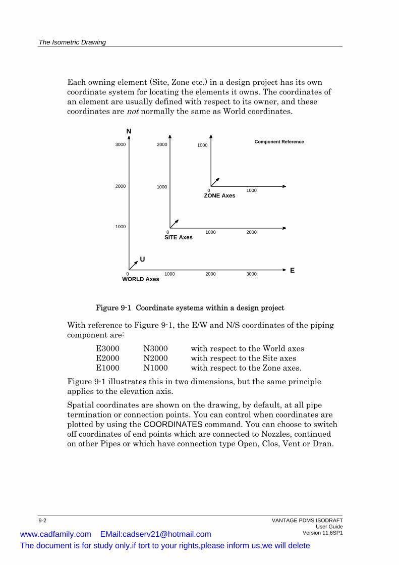
The Isometric Drawing
Each owning element (Site, Zone etc.) in a design project has its own coordinate system for locating the elements it owns. The coordinates of an element are usually defined with respect to its owner, and these coordinates are not normally the same as World coordinates.
1000 2000 30000
1000
3000
2000
Component Reference
ZONE Axes
SITE Axes
WORLD Axes
N
E
0 1000 2000
1000
2000 1000
10000
U
Figure 9-1 Coordinate systems within a design project
With reference to Figure 9-1, the E/W and N/S coordinates of the piping component are:
E3000 N3000 with respect to the World axes E2000 N2000 with respect to the Site axes E1000 N1000 with respect to the Zone axes.
Figure 9-1 illustrates this in two dimensions, but the same principle applies to the elevation axis. Spatial coordinates are shown on the drawing, by default, at all pipe termination or connection points. You can control when coordinates are plotted by using the COORDINATES command. You can choose to switch off coordinates of end points which are connected to Nozzles, continued on other Pipes or which have connection type Open, Clos, Vent or Dran.
9-2 VANTAGE PDMS ISODRAFT User Guide Version 11.6SP1 www.cadfamily.com EMail:[email protected]
The document is for study only,if tort to your rights,please inform us,we will delete

The Isometric Drawing
9.3.1 Elevations
By default, elevations are only shown at intersection points when there is a change of elevation. Elevations can be shown on vertical sections of pipe by using the ELEVATION command.
9.4 Improving Legibility of the Isometric
ISODRAFT tries to balance the amount of information shown on a drawing sheet and its legibility. If the default is not satisfactory, you can improve the legibility by increasing the character size on the drawing area, and by altering the picture scale. • The character size for the annotating text on the isometric drawing
can be specified using the CHARSIZE command. Note that the character size for the material list is specified using the MATERIALLIST command.
• The scale of the isometric area can be changed by using the PICTURESCALE command. Note that this does not scale the whole isometric, but just affects the size of the symbols and annotation relative to the length of pipe shown. The material list is not affected.
9.4.1 Message Layout
You can control how arrowed messages on the isometric are positioned on the isometric using the MESSAGEACCURACY command. The MESSAGEACCURACY RADIAL option determines the accuracy level of the radial search, based on the number of radial directions searched away from the arrowhead, the number of additional directions for kinked lines, and the length of increments of leader lines. The levels are as follows: Level Radial directions Additional directions Length searched away for kinked lines increment from arrowhead of leader line
1 18 directions @ 20 degrees 2 directions @ 80 degrees 4mm 2 36 directions @ 10 degrees 4 directions @ 40, 80degrees 2mm 3 72 directions @ 5 degrees 8 directions @ 20, 40, 80 degrees 1mm
Once all messages have been positioned, the MESSAGEACCURACY ITERATIONS option repositions any messages with crossing leader lines, and all messages with leader lines passing through the text block. You
VANTAGE PDMS ISODRAFT 9-3 User Guide Version 11.6SP1 www.cadfamily.com EMail:[email protected]
The document is for study only,if tort to your rights,please inform us,we will delete
The Isometric Drawing
can set a maximum number of iterations, and the process is repeated until one of the following conditions is satisfied: • No leader lines cross and no messages need to be moved. • The number of leader lines crossing and messages moving is the
same as the previous iteration. • The maximum number of iterations set by the option is reached. You should start with accuracy level 1. Higher accuracy levels are achieved at the expense of performance. Increasing the number of iterations is not as expensive as higher accuracy levels, as often an equilibrium is reached before the maximum number of iterations. Thus it is recommended that the effect of increasing iterations be examined before increasing the accuracy level.
9.5 Splitting Long Pipelines
If a pipeline is too long or complex to fit on a single isometric plot, ISODRAFT will automatically split the pipeline over separate drawings. The split may occur in a main line or an off-line section. Each drawing will be identified as DRG 1 OF ..., DRG 2 OF ..., etc. You can control the style of numbering using the MATERIALLIST command. You can control the complexity of each drawing, or the number of drawings into which the isometric is to be split, by using the SPLIT command. When a pipe is continued on another drawing, the pipe end will carry the message CONT. ON followed by the identification of the next drawing. When a pipe is continued from a preceding drawing, the pipe end will carry the message CONT. FROM followed by the identification of the preceding drawing. ISODRAFT may generate splits in tube. You can use the TUBESPLITS command to generate the message UNACCEPTABLE SPLIT POINT when splits in tube occur, or to stop isometrics with splits in tube being produced at all.
9.5.1 Specifying Split Points
You can specify exactly where pipes should be split by using split ATTAs in the Design database. The principles are described in Chapter 5, Design Requirements. If user-defined positions for splits have been
9-4 VANTAGE PDMS ISODRAFT User Guide Version 11.6SP1 www.cadfamily.com EMail:[email protected]
The document is for study only,if tort to your rights,please inform us,we will delete
The Isometric Drawing
created in the design, ISODRAFT will always use these and not calculate its own split points. Note: Although ISODRAFT will sometimes split isometrics between
flanges automatically, it is important that you do not position any ATTAs between flanges or flanged fittings. To do so could lead to corruption of the ISODRAFT Material List output.
9.5.2 Repeatability
When a pipe is detailed which needs splitting over more than one sheet, ISODRAFT automatically generates split points. By default this data is not stored, so if the design is altered and the pipe detailed again, the split points may be in different places. If you use the REPEATABILITY command, sheet split points are written back into the design database. This means that when the pipe is detailed again it will be split in the same places. You can reposition the split points if you wish. Repeatability allows you to re-plot single sheets when you have made changes to your design which only affect those sheets. Repeatability is not available for system isometrics or equipment trims. The split points are not set by ISODRAFT; an inter-DB connection macro is generated to set them in DESIGN.
Restrictions on Repeatability • Split ATTAs will not be automatically created if some already exist
in the pipe. • Re-ordering branches will destroy the integrity of the repeatability
data. For a major redesign, you should remove repeatability data from the database and regenerate it. If repeatability has been set, individual spools and sheets can be re-plotted using the DETAIL command. Individual sheets and spools can be entered into the Add and Remove lists using the ADD and REMOVE commands.
VANTAGE PDMS ISODRAFT 9-5 User Guide Version 11.6SP1 www.cadfamily.com EMail:[email protected]
The document is for study only,if tort to your rights,please inform us,we will delete

The Isometric Drawing
9.6 Dimensioning
ISODRAFT can output several types of dimensions with different amounts of detail. The main types of dimensioning are: • String dimensions (the default). • Composite dimensions. • Overall dimensions. • Support dimensions. The different types are illustrated in Figure 9-2. String dimensions are measured between the following points: • The start or end of a branch • Changes of direction (bends, elbows etc.) • Component connection points (flanges, welds, screwed and
compression joints etc., excluding gaskets) Composite dimensioning ignores dimensions which the fabricator has no control over, particularly the sizes of individual components. Components which are directly connected to each other are therefore dimensioned as though they constitute a single composite item. Overall dimensions indicate the lengths of the following sections of a pipeline: • From the start of a branch to the first change of direction • From each change of direction to the next • From the last change of direction to the end of a Branch • From the start of a falling section skew-box to the end of the falling
section skew-box. • Between Branch connections. You can specify: • Whether or not overall dimensions cross Branch connections • Dimensioning to Valve centrelines You can specify that overall dimensioning is to critical components. This can be used when the exact lengths of all components are not known at the time of design, for example, if the purchase of fittings has been delegated to a local fabricator. Critical dimensions are between points on assemblies of connected components. The points are chosen according to the first rule satisfied from the following list:
9-6 VANTAGE PDMS ISODRAFT User Guide Version 11.6SP1 www.cadfamily.com EMail:[email protected]
The document is for study only,if tort to your rights,please inform us,we will delete
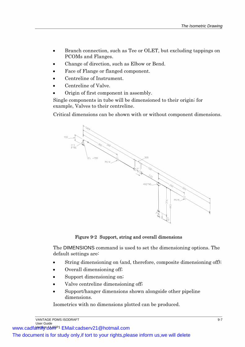
The Isometric Drawing
• Branch connection, such as Tee or OLET, but excluding tappings on PCOMs and Flanges.
• Change of direction, such as Elbow or Bend. • Face of Flange or flanged component. • Centreline of Instrument. • Centreline of Valve. • Origin of first component in assembly. Single components in tube will be dimensioned to their origin; for example, Valves to their centreline. Critical dimensions can be shown with or without component dimensions.
Figure 9-2 Support, string and overall dimensions
The DIMENSIONS command is used to set the dimensioning options. The default settings are: • String dimensioning on (and, therefore, composite dimensioning off); • Overall dimensioning off; • Support dimensioning on; • Valve centreline dimensioning off; • Support/hanger dimensions shown alongside other pipeline
dimensions. Isometrics with no dimensions plotted can be produced.
VANTAGE PDMS ISODRAFT 9-7 User Guide Version 11.6SP1 www.cadfamily.com EMail:[email protected]
The document is for study only,if tort to your rights,please inform us,we will delete
The Isometric Drawing
9.6.1 Support/Hanger Dimensions
Support positions can be dimensioned in one of two ways, overall or string. The default is string, and this can be changed using the SUPPORTS command. Support information may be omitted completely from the isometrics. By default, support/hanger dimensions are positioned with a standout of 6mm and overall dimensions are positioned at with a standout of 16mm on the same side of the pipe as string dimensions (see Figure 9-2 and Figure 9-3). You can use the DIMENSIONS HANGERS command to position support/hanger dimensions at one standout on the opposite side from string dimensions (see Figure 9-3).
9.6.2 Bend Radii
Bend radii will be output, by default, for all pulled bends (that is for all components with SKEYs beginning with PB). Bend radii can be shown either in distance units or as multiples of pipe diameters (where pipe diameter is taken as the nominal bore of the pipe) by using the BENDRADIUS command. Output of bend radii can also be suppressed. A standard radius for bends can be set using the BENDRADIUS STANDARD command. It can be positioned as a note on the isometric plot using the POSITION command. If a standard radius is set, only bends which have radii different from the standard radius will have their radii shown individually. Both the standard radius and any individual radii will be shown in the same format (i.e. in distance units or in pipe diameters). Note that only the actual value of the standard radius will be output. Any other text, such as: All pulled bends to be D unless otherwise shown
where the value is positioned in the space immediately before the D, must be plotted by some other method, such as an underlay. See the UNDERLAYPLOTFILE command.
9-8 VANTAGE PDMS ISODRAFT User Guide Version 11.6SP1 www.cadfamily.com EMail:[email protected]
The document is for study only,if tort to your rights,please inform us,we will delete

The Isometric Drawing
Support/
String / Composite
Overall
String Composite
Overall
(a) Dimensions Hangers
(b) Dimensions Hangers (Opposite Strings)
11mm
5mm
11mm
(Default)
Hanger
Support/Hanger
16mm
6mm
6mm
Figure 9-3 Dimensioning line standout distances (default standout distances)
9.6.3 Dimensional Units on Isometrics
The units for output are specified independently from the units for input. By default, ISODRAFT outputs metric lengths and imperial bores, but these can be changed so that output is all imperial units or all metric units using the UNITS command. You can also choose whether bores are Nominal or Actual using the PRECISION BORES command.
9.6.4 Rounding and Truncation of Dimensions
When dimensioned isometrics are plotted, all dimensions are rounded up or down to the nearest mm or 1/16 inch (depending on the units set by the UNITS command). By default, ISODRAFT carries over the remainder (positive or negative) from a rounded dimension and adds it to the next dimension. Carrying over the rounding remainder reduces cumulative
VANTAGE PDMS ISODRAFT 9-9 User Guide Version 11.6SP1 www.cadfamily.com EMail:[email protected]
The document is for study only,if tort to your rights,please inform us,we will delete
The Isometric Drawing
errors over a number of consecutive dimensions, but it can result in identical fittings being shown with different lengths (usually differing by 1mm or 1/16 inch). If you wish to suppress this carry over effect, you can specify that ISODRAFT truncates all dimensions. The remainders from rounding of the individual dimensions will then be discarded rather than added to the next dimension. To specify truncation, use the TRUNCATE command.
9.6.5 Positions of Dimensioning Lines
The default standout distance between string/composite dimensioning lines and the pipe runs to which they apply is 11mm. The default overall and support dimension distances are 16mm and 6mm, respectively. The standout distances can be changed separately for string, overall and support dimensions by using the DIMDIST command. They may not be set to the same value.
9.6.6 Reference Dimensions
If reference dimensions have been set up in the Design database, they can be switched on using the REFDIMENSIONS command. See Section 5.3 for information about how to set up reference dimensions in the Design database.
9.7 Support Attachment Point Names
By default, the names of support attachment points (that is, all ATTAs for which the ATTY attribute is unset) are not shown on the isometric plot and their SPREFs (specification references) are used as their item codes. You can use the ATTANAME command to display the PDMS names of support ATTAs on the drawings, and to specify whether their PDMS names or their SPREFs are used as their item codes.
9-10 VANTAGE PDMS ISODRAFT User Guide Version 11.6SP1 www.cadfamily.com EMail:[email protected]
The document is for study only,if tort to your rights,please inform us,we will delete
The Isometric Drawing
9.8 Tolerances In Isometric Plotting
By default, two components will be plotted as though they have a common axis if the orientation of their axes differs by less than 0.06 degrees, or if their axes are offset by less than 1.00 mm. The TOLERANCE command allows you to specify a different alignment tolerance, either as an angular difference or as a linear offset.
9.9 Flow Arrows
Two types of flow arrow can be plotted on isometric drawings: • Arrows alongside in-line components (Valves etc.) • In-line arrows at specified points in Tube, if these have been defined
in the Design database. You can control whether each type is plotted, and the inline flow arrows can be scaled, using the FLOWARROWS command.
9.10 Plotted Leg Length
By default, the plotted leg length of Elbows, Tees and Crosses is 9mm. You can change this value by giving the LEGLENGTH command. The minimum leg length allowed is 6mm.
9.11 Skewed and Falling Pipelines
9.11.1 Skewed Lines
Skewed pipelines are shown by skewboxes (that is by boxing in the skewed length with dimensioning lines which show the horizontal and vertical differences between the end coordinates). The skewboxes can be full boxes or triangles, as specified by the SKEWBOX command. If triangles are is specified, five further options are available: • The dimensions can be shown in standard form or in a non-standard
form • The triangle areas can be shown hatched (shaded) or un-hatched • Swing angles can be displayed in the corners of the triangles
VANTAGE PDMS ISODRAFT 9-11 User Guide Version 11.6SP1 www.cadfamily.com EMail:[email protected]
The document is for study only,if tort to your rights,please inform us,we will delete

The Isometric Drawing
• H and V notes can be shown in the right angle corners of horizontal and vertical triangles
• Overall skewboxes, or skewboxes between branches can be shown Skewbox triangles can have two styles of dimensioning: • Standard dimensioning shows the horizontal and vertical dimension
lines of the triangle standing out from the sides of the triangle. • Non-standard dimensioning shows the dimension characters
positioned along the sides of the triangle itself. The default is standard dimensioning.
By default, skewbox triangles are highlighted by parallel-line hatching with a spacing of 3mm between the hatching lines. The hatching can be switched off, or the spacing altered. You can specify whether triangular skewboxes are shown as overall skewboxes across branches, or as separate skewboxes between branch connections using the OVERALLSKEWS command.
9.11.2 Falling Lines
Falling lines are shown by skewboxes in the same way as other skewed lines. If the amount of fall is less than the current fall limit, the fall is shown by a wedge-shaped symbol on the pipe showing the direction of fall, and the word FALL followed by the amount of fall in degrees. The symbol is known as a fall arrow. By default, the fall limit is 5°. This limit can be changed, or expressed in different units using the FALLINGLINES command. The accuracy of reporting the fall amount can be varied. The fall arrow and slope method can be switched off completely, and all falls will then be shown as skewboxes.
9.11.3 Skewed and Falling Lines
By default, skewed and falling lines are showed by 3D skewboxes (that is one skewbox to show the fall and one to show the horizontal skew). Skewed and falling lines with falls less than the current fall limit can be shown by an arrow on the pipe showing the direction of fall, and the word FALL followed by the amount of fall. A single (2D) skewbox shows the horizontal skew in this case. See the FALLSKEWS command. You can also suppress skewboxes showing falls for branch legs which have less than a given number of components.
9-12 VANTAGE PDMS ISODRAFT User Guide Version 11.6SP1 www.cadfamily.com EMail:[email protected]
The document is for study only,if tort to your rights,please inform us,we will delete

The Isometric Drawing
9.11.4 Zero-length Bends at Tees and OLETs
When modelling falling lines containing Butt Weld Tees or OLETs, you can position a zero-length variable-angle bend at the off-line p-point of each Tee or OLET. The use of zero-length bends allows you to connect a vertical Branch to a falling line. To suppress the output of skewbox dimensions at zero-length bends in these circumstances, use the command ZEROLENGTHSKEWS. The default setting is ZEROLENGTHSKEWS ON, which displays Tees and OLETs as shown in Figure 9-4(a). The effect of specifying ZEROLENGTHSKEWS OFF is shown in Figure 9-4(b). Note: Bends at Tees or OLETs will only be considered as zero-length if
they are less than 0.5mm long. Bends with dimensions greater than this will be detailed as normal components.
.
0.6_ 0.6_
ORIENTATION DIRECTIONU 0.6 E
FALL FALL
0.6_ 0.6_
FALL FALL
(a) ZEROLENGTHSKEWS ON(Default)
(b) ZEROLENGTHSKEWS OFF
Figure 9-4 Suppressing skewboxes at Tees and OLETs
VANTAGE PDMS ISODRAFT 9-13 User Guide Version 11.6SP1 www.cadfamily.com EMail:[email protected]
The document is for study only,if tort to your rights,please inform us,we will delete

The Isometric Drawing
9.12 Insulation and Tracing
Any pipe which has its Insulation Specification (ISPEC) and/or Heat Tracing Specification (TSPEC) attributes set can be identified on the isometric drawings as shown in Figure 9-5.
Insulated Traced Insulated and Traced
Figure 9-5 Insulated and traced piping
The start and end points of insulation on a line can be indicated on a drawing as shown in Figure 9-6.
START OF INSULATIONFOR 2.0M
INSU IN51
END OF INSULATIONAT EL10250
Figure 9-6 Insulation Start and Stop symbol example
The insulation specification note will be shown on the drawing at the start points of any insulation. The name of the tracing specification will be shown in the title block. Insulation and tracing can be shown either on tubing only, or on tubing and pipe components. The commands to control the display of tracing and insulation are INSULATIONCONTROL and TRACINGCONTROL.
9-14 VANTAGE PDMS ISODRAFT User Guide Version 11.6SP1 www.cadfamily.com EMail:[email protected]
The document is for study only,if tort to your rights,please inform us,we will delete
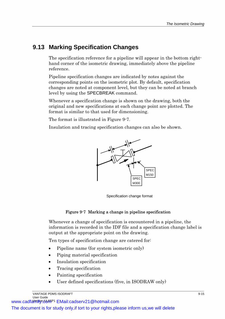
The Isometric Drawing
9.13 Marking Specification Changes The specification reference for a pipeline will appear in the bottom right-hand corner of the isometric drawing, immediately above the pipeline reference. Pipeline specification changes are indicated by notes against the corresponding points on the isometric plot. By default, specification changes are noted at component level, but they can be noted at branch level by using the SPECBREAK command. Whenever a specification change is shown on the drawing, both the original and new specifications at each change point are plotted. The format is similar to that used for dimensioning. The format is illustrated in Figure 9-7. Insulation and tracing specification changes can also be shown.
Specification change format
SPECM300
SPECM150
Figure 9-7 Marking a change in pipeline specification
Whenever a change of specification is encountered in a pipeline, the information is recorded in the IDF file and a specification change label is output at the appropriate point on the drawing. Ten types of specification change are catered for: • Pipeline name (for system isometric only) • Piping material specification • Insulation specification • Tracing specification • Painting specification • User defined specifications (five, in ISODRAW only)
VANTAGE PDMS ISODRAFT 9-15 User Guide Version 11.6SP1 www.cadfamily.com EMail:[email protected]
The document is for study only,if tort to your rights,please inform us,we will delete
The Isometric Drawing
A maximum of ten changes are allowed at a single point. Each specification type has an associated, user-definable ATEXT which specifies the text printed alongside each specification. See the SPECBREAK command in Chapter 2 of the VANTAGE PDMS ISODRAFT Reference Manual.
9.14 Plotting Complete System Isometrics
9.14.1 System Isometrics
Normally, ISODRAFT will process each pipe or spool drawing specified in a DETAIL command separately. However, they can be detailed as a complete system isometric. See the DETAIL command for more information.
9.14.2 Equipment Trims for Material Take Off
Unconnected items cannot be drawn automatically as part of a system isometric, vessel or equipment trim. However, drawings consisting of a drawing frame, user-positioned text and a material list can be produced for material take off. The graphical part of the drawing can then be added separately if required. Groups of components such as blanking flanges, level gauges, relief valves, etc., may be modelled on the basis of one Pipe per Nozzle, or per group of Nozzles if connected (such as a level gauge piped between two Nozzles). Disconnected branches in the same pipe on different nozzles cannot be grouped. The collection of pipes may then be detailed as equipment trim. By default, item numbering in the material list will start at 1 for each Nozzle. To get continuous numbering throughout the sequence of Nozzles, use the EQUIPMENTNUMBERING command.
9-16 VANTAGE PDMS ISODRAFT User Guide Version 11.6SP1 www.cadfamily.com EMail:[email protected]
The document is for study only,if tort to your rights,please inform us,we will delete
The Isometric Drawing
9.15 Welds
9.15.1 Weld Display
The following weld types have symbols associated with them. They can therefore be shown on isometrics:
WS Site (erection) weld WF Field-fitted weld WW Shop (fabrication) weld
By default, all types of weld are shown on isometrics. You can use the WELDTYPE command to specify that: • Only shop welds will be shown; • Only site welds will be shown; • No welds will be shown; • All welded fittings will be shown as having shop welds.
9.15.2 Weld Numbering
You can assign unique numbers automatically to welds in the SPOOLER module, thereby providing complete weld traceability. Numbering can be applied to an individual pipe, branch or spool drawing. These unique identities are stored in the Design database, and are available for you to use in ISODRAFT (see the WELDNUMBERS command). If you use this feature, you can also create a table of all numbered welds (according to your own specifications) to be included on the isometric. If you use weld numbers from the design database, temporary weld numbers can be output by ISODRAFT at end points where the weld actually belongs to another drawing. These temporary numbers are also included in the weld table. This will allow the fabricator to identify the end preparation to be applied to the termination joint even though the weld is not to be made for this drawing. Temporary weld numbers will include the weld prefix but will use letters instead of numbers. If you do not use the automatic weld numbering feature of SPOOLER, you can number the welds on an isometric within ISODRAFT using the WELDNUMBERS command (however, numbers generated this way are not maintained between revisions). You can also use the WELDNUMBERS command to specify that a table of all numbered welds will be drawn immediately above the title block. Additional welds can be shown on the isometric either in individual balloons or, if there are more than a specified number of them, as an
VANTAGE PDMS ISODRAFT 9-17 User Guide Version 11.6SP1 www.cadfamily.com EMail:[email protected]
The document is for study only,if tort to your rights,please inform us,we will delete

The Isometric Drawing
arrowed message in a single ellipse (with the numbers separated by slashes). You specify this by appending AWELD BALLOON number to the WELDNUMBERS command. Either with numbers from the Design DB, or generated within ISODRAFT, you can specify the size of the characters for the numbers, and whether fabrication or erection welds or both are to be numbered. Note that by combining the DIMENSIONS OFF and WELDNUMBERS options it is possible to obtain un-dimensioned isometric drawings with weld numbers on them. These are useful for recording the results of weld radiography inspections.
9.15.3 Weld Identification
Welds which have their NAME attribute set in the DESIGN database can have their names plotted against their symbols on the isometric by using the WELDID command.
9.16 Item Codes and Name Tags on Isometrics
9.16.1 Item Codes
By default, item codes for piping components are shown only in the material list. For in-line fittings of generic types INST, VALV, FILT, PCOM, TRAP or VENT, you can specify that item codes are also shown against the corresponding component symbols on the isometric plot by using the ITEMCODE command.
9.16.2 Name Tags
By default, component names are not plotted. Fittings of generic type INST, VALV, FILT, PCOM, TRAP, VTWA, VFWA and VENT can have their PDMS names (if they have them) shown against their plotted symbols on the isometric by using the TAGGING command. (See also the KEYS command.)
9.16.3 User-defined Tag Boxes
You can use the OUTCOM command to output piping component attributes and user-defined attributes on the isometric drawing area.
9-18 VANTAGE PDMS ISODRAFT User Guide Version 11.6SP1 www.cadfamily.com EMail:[email protected]
The document is for study only,if tort to your rights,please inform us,we will delete
The Isometric Drawing
You can choose whether the text is boxed or unboxed, and the style of box used. You can also output empty boxes for manual mark-up. Six styles are available: • A rectangular box with straight ends • A rectangular box with angled ends • A rectangular box with round ends • A triangular box • A diamond-shaped box • Unboxed
9.17 Pipe Ends and Connecting Nozzles
9.17.1 Suppression of End Coordinates
The output of end coordinates may be suppressed at locations such as: • Pipeline continuations to other drawing sheets; • Nozzle connections; • End connection types OPEN, CLOS, VENT or DRAN. To specify whether or not end coordinates are to be shown at one or more types of location, use the COORDINATES command.
9.17.2 Nozzle Continuation Symbols
On combined or erection-only isometrics, dotted nozzles can be plotted at points where connections are made to plant equipment, using the CONTINUATIONSYMBOLS command.
9.17.3 Continuation Notes
You can determine whether continuation notes should be included on the isometric for when drawings continue onto another isometric. The notes can include the names of pipes, drawings or both (as defined by the DESIGN Spooling application) using the CONTNOTES command. If the termination point on the current isometric is a weld, you can include a description of the connecting component or tube in the notes. The notes will tell you where the continuation is made to, and can include the relevant description.
VANTAGE PDMS ISODRAFT 9-19 User Guide Version 11.6SP1 www.cadfamily.com EMail:[email protected]
The document is for study only,if tort to your rights,please inform us,we will delete
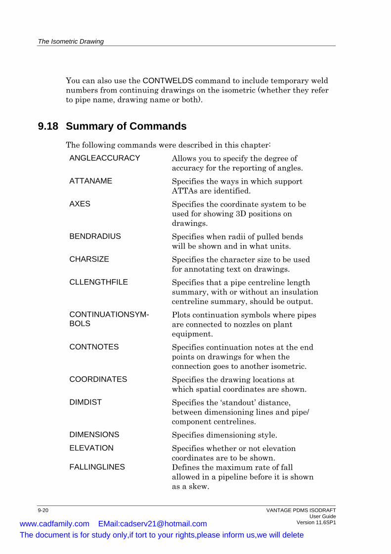
The Isometric Drawing
You can also use the CONTWELDS command to include temporary weld numbers from continuing drawings on the isometric (whether they refer to pipe name, drawing name or both).
9.18 Summary of Commands The following commands were described in this chapter: ANGLEACCURACY Allows you to specify the degree of
accuracy for the reporting of angles. ATTANAME Specifies the ways in which support
ATTAs are identified. AXES Specifies the coordinate system to be
used for showing 3D positions on drawings.
BENDRADIUS Specifies when radii of pulled bends will be shown and in what units.
CHARSIZE Specifies the character size to be used for annotating text on drawings.
CLLENGTHFILE Specifies that a pipe centreline length summary, with or without an insulation centreline summary, should be output.
CONTINUATIONSYM-BOLS
Plots continuation symbols where pipes are connected to nozzles on plant equipment.
CONTNOTES Specifies continuation notes at the end points on drawings for when the connection goes to another isometric.
COORDINATES Specifies the drawing locations at which spatial coordinates are shown.
DIMDIST Specifies the ‘standout’ distance, between dimensioning lines and pipe/ component centrelines.
DIMENSIONS Specifies dimensioning style. ELEVATION Specifies whether or not elevation
coordinates are to be shown. FALLINGLINES Defines the maximum rate of fall
allowed in a pipeline before it is shown as a skew.
9-20 VANTAGE PDMS ISODRAFT User Guide Version 11.6SP1 www.cadfamily.com EMail:[email protected]
The document is for study only,if tort to your rights,please inform us,we will delete
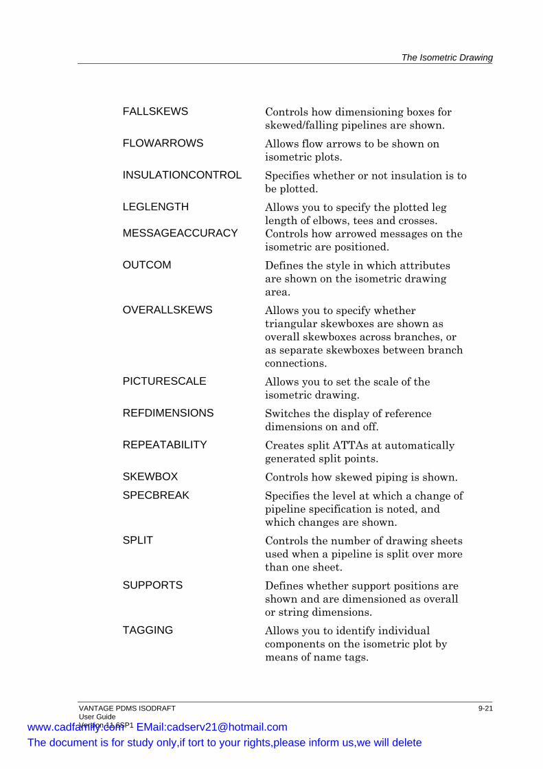
The Isometric Drawing
FALLSKEWS Controls how dimensioning boxes for skewed/falling pipelines are shown.
FLOWARROWS Allows flow arrows to be shown on isometric plots.
INSULATIONCONTROL Specifies whether or not insulation is to be plotted.
LEGLENGTH Allows you to specify the plotted leg length of elbows, tees and crosses.
MESSAGEACCURACY Controls how arrowed messages on the isometric are positioned.
OUTCOM Defines the style in which attributes are shown on the isometric drawing area.
OVERALLSKEWS Allows you to specify whether triangular skewboxes are shown as overall skewboxes across branches, or as separate skewboxes between branch connections.
PICTURESCALE Allows you to set the scale of the isometric drawing.
REFDIMENSIONS Switches the display of reference dimensions on and off.
REPEATABILITY Creates split ATTAs at automatically generated split points.
SKEWBOX Controls how skewed piping is shown. SPECBREAK Specifies the level at which a change of
pipeline specification is noted, and which changes are shown.
SPLIT Controls the number of drawing sheets used when a pipeline is split over more than one sheet.
SUPPORTS Defines whether support positions are shown and are dimensioned as overall or string dimensions.
TAGGING Allows you to identify individual components on the isometric plot by means of name tags.
VANTAGE PDMS ISODRAFT 9-21 User Guide Version 11.6SP1 www.cadfamily.com EMail:[email protected]
The document is for study only,if tort to your rights,please inform us,we will delete
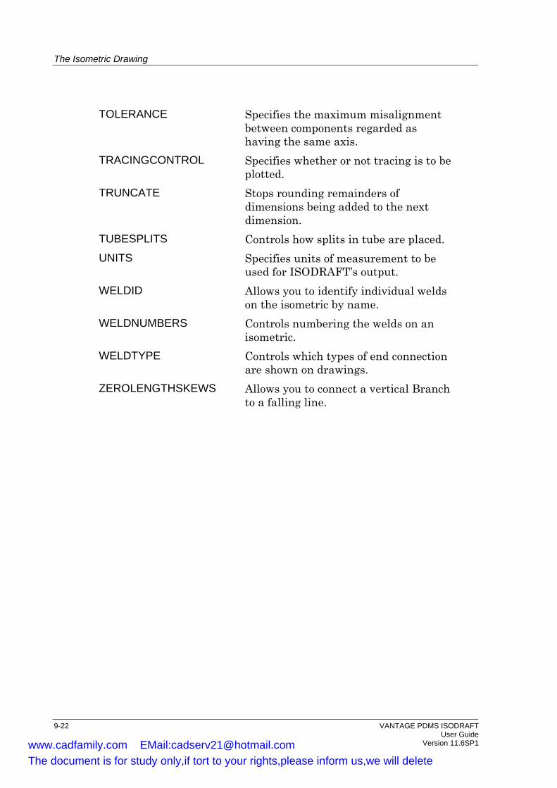
The Isometric Drawing
TOLERANCE Specifies the maximum misalignment between components regarded as having the same axis.
TRACINGCONTROL Specifies whether or not tracing is to be plotted.
TRUNCATE Stops rounding remainders of dimensions being added to the next dimension.
TUBESPLITS Controls how splits in tube are placed. UNITS Specifies units of measurement to be
used for ISODRAFT’s output. WELDID Allows you to identify individual welds
on the isometric by name. WELDNUMBERS Controls numbering the welds on an
isometric. WELDTYPE Controls which types of end connection
are shown on drawings. ZEROLENGTHSKEWS Allows you to connect a vertical Branch
to a falling line.
9-22 VANTAGE PDMS ISODRAFT User Guide Version 11.6SP1 www.cadfamily.com EMail:[email protected]
The document is for study only,if tort to your rights,please inform us,we will delete

10 Drawing Change Highlighting
10.1 Highlighting
The Change Highlighting function defines if and how modified data is highlighted on the isometric since a given comparison date. The comparison date is described in Section 10.2. The Change Highlighting function can be turned ON or OFF. A Change Highlight colour can be selected and will be used for highlighting all changes. If highlighting is switched ON, entries in tables and material lists, annotations, labels and dimensions will always be drawn in the highlight colour if they have changed since the comparison date. Change Highlight Rules can be defined to specify which components are to be represented in the selected change highlight colour. • If no rules have been defined then no components will be shown in
the highlight colour. • If ALL components have been selected, but no conditions defined,
then ALL components will be in the highlight colour regardless of whether anything has changed.
Using ELBO as an example: • If ELBO components have been selected, but no conditions defined,
then all ELBOs will be in the highlight colour regardless of whether anything has changed.
• If ELBO components have been selected with the MODIFIED() condition, then all ELBOs will be in the highlight colour only if the ELBO has changed.
• If ELBO components have been selected with the MODIFIED(POS) condition, then all ELBOs will be in the highlight colour only if the Position of the ELBO has changed.
Note that any items deleted after the comparison date cannot be identified on the isometric. (They can be queried.) The user must ensure that the options used on each run are the same. Differing options cannot be controlled by the program.
VANTAGE PDMS ISODRAFT 10-1 User Guide Version 11.6SP1 www.cadfamily.com EMail:[email protected]
The document is for study only,if tort to your rights,please inform us,we will delete
Drawing Change Highlighting
When labelling grouped components, such as 'F8 L9 G10 B11', in boxed text it will not be possible to isolate the changed item. The user must look at the material list to see which of the grouped components has changed. This is particularly important for bolts and gaskets as these components are never represented on the isometric other than by label. Change Highlighting options are set using the Change Highlighting form from the Options Create/Modify functions. • Checking the Show Change Highlighting checkbox sets the Change
Highlighting function to ON, unchecking it sets the function to OFF. • Clicking on the Colour button brings up the Highlight Colour form.
Use this to select the desired highlight colour. • Use the Create, Delete and Clear buttons to:
• Create a new Highlight Rule. • Delete a selected Highlight Rule. • Delete all Highlight Rules.
• Use the For drop-down list to select a component type that you want to be associated with the selected Highlight Rule. Use the Add button to make the association. Any number of components can be added as required.
• If you want to remove a component type from the selected Highlight Rule, select the component type using the For drop-down list, then click the Remove button.
• Use the With text box to add a qualifier to the component selected in the For drop-down list to make it more specific, for example: MODIFIED (POS) or CREATED().
• Click on the Apply button to save the current form settings to the Option file.
• Click on the Dismiss button to close the form without saving any modifications made.
For syntax related to change highlighting refer to the VANTAGE PDMS ISODRAFT Reference Manual.
10.2 The Comparison Date
It is only by comparing a drawing at two states or sessions that it is possible to determine what has changed. Using the current state of the drawing as one state we must then reference an earlier state in order to make the comparison. We do this by specifying a Comparison Date:
10-2 VANTAGE PDMS ISODRAFT User Guide Version 11.6SP1 www.cadfamily.com EMail:[email protected]
The document is for study only,if tort to your rights,please inform us,we will delete

Drawing Change Highlighting
(COMPDATE), that is, the drawing state at a time that we wish to use as a baseline or datum. If no Comparison Date has been defined then an error is raised and isometric production is aborted. The Comparison Date is set from the Set Comparison Date form. The Comparison Date can be set in one of two ways: • By specifying an actual time and date. • By referencing a Stamp:. A Stamp is a way of referencing combinations of databases and sessions at specified instances. Stamps are created in ADMIN. For more information on Stamps and how they are created and used refer to the VANTAGE PDMS ADMIN Command Reference Manual and the VANTAGE PDMS ADMIN User Guide.
10.3 Summary of Commands
The following commands were described in this chapter:
SETCOMPDATE Specifies the Comparison Date to be used to determine what has changed on an isometric.
CHANGE HIGHLIGHTING Switch ON/OFF, select a colour, define Highlighting Rules for components.
VANTAGE PDMS ISODRAFT 10-3 User Guide Version 11.6SP1 www.cadfamily.com EMail:[email protected]
The document is for study only,if tort to your rights,please inform us,we will delete

Drawing Change Highlighting
10-4 VANTAGE PDMS ISODRAFT User Guide Version 11.6SP1 www.cadfamily.com EMail:[email protected]
The document is for study only,if tort to your rights,please inform us,we will delete
11 Symbol Keys
Each type of component has a symbol which is used to represent it on the isometric drawings. A set of default symbols for a wide range of components is supplied with ISODRAFT. The symbols supplied in the standard library are shown in Chapter 3 of the VANTAGE PDMS ISODRAFT Reference Manual. You can query the SKEYs in the symbol library index, but you cannot query symbol attributes and shape definitions. The symbols are linked to the components they represent in the Catalogue database via the SKEY (symbol key) attribute of a DTEXT element. You can create new symbols in PDMS DRAFT or other 2D drawing packages. There is on-line help for the forms and menus used to create the symbols in DRAFT, and the information is also available in the VANTAGE PDMS DRAFT Administrator Application User Guide. The commands to create symbols are described in the VANTAGE PDMS DRAFT User Guide. This chapter explains the way ISODRAFT handles the symbols.
11.1 The Basic Principles
Any new symbol must be derived from an existing symbol which has the required characteristics; however, the existing symbol need not be for a component with the same generic type (GTYPE) as the new one. Items such as Bends, Elbows, Tees and Crosses, which are drawn as pieces of tube rather than as symbols, cannot be redefined. Other specific components which cannot be redefined are indicated by a ‘No’ entry in the USER DEFINABLE? column of the SKEY Reference Section in Chapter 3 of the VANTAGE PDMS ISODRAFT Reference Manual. You should not redefine the symbols for Instrument Dials (with SKEYs IDFL and IDPL) because their circular shapes are used to store instrument references and are therefore not converted from orthogonal to isometric symbol shapes. The maximum number of user-defined symbols which may exist at any time is 300.
VANTAGE PDMS ISODRAFT 11-1 User Guide Version 11.6SP1 www.cadfamily.com EMail:[email protected]
The document is for study only,if tort to your rights,please inform us,we will delete
Symbol Keys
Many standard symbols consist of a number of separate smaller symbols; for example, the symbol for a valve incorporates a body symbol, a spindle symbol and end symbols. In this case the body and spindle symbols may be separately redefined in DRAFT, while the end symbols may be modified in PARAGON, as explained in Chapter 3, Cataloguing Requirements. Note: Take care that symbols are not so large that they overlap other
information, such as dimensioning data, on the drawings. It may be necessary to adjust other aspects of the isometric, such as the standout distance of dimensions, in order to maintain legibility.
11.2 Symbol Attributes
The attributes of ISODRAFT Symbol Templates are set in DRAFT, where the symbol templates are defined. They are as follows:
SCale val Changes the size of the symbol without re-defining the coordinates of the plotted shape (100 = full size).
ORIentation NONE Specifies a symmetrical fitting which the flow direction is not relevant.
ORIentation FLOW Specifies a fitting for which the flow direction is important, such as check valves.
ORIentation REDUcer Specifies a reducing fitting.
ORIentation FLANge Specifies a fitting which begins with a flange; that is, one which is preceded by a gasket.
FLWA TRUE Plots flow arrows on the symbol. FLWA FALSE Suppresses flow arrows. DIMEnsion ON
Plots dimensions alongside the symbol. DIMEnsion OFF
Suppresses the plotting of dimensions. Fill
Enables default and user-defined symbols to be drawn as filled polygons.
11-2 VANTAGE PDMS ISODRAFT User Guide Version 11.6SP1 www.cadfamily.com EMail:[email protected]
The document is for study only,if tort to your rights,please inform us,we will delete

Symbol Keys
User-defined symbols based on the following SKEYs and defined with ORI FLAN or ORI REDU will be automatically flipped to fit in with the pipeline component sequence.
GTYPE SKEY Description CAP All All caps FLAN All All flanges LJSE All All lap joints stub ends PCOM PL Plug REDU All All reducers
User-defined symbols based on the following SKEYs and defined with ORI FLOW will be automatically flipped depending on the flow direction.
GTYPE SKEY Description INST DR Rupture disk INST XV** Pressure reducing valve PCOM TU** Tundish (funnel) VALV CK** Check valve VALV VX** Pressure reducing valve VENT RD Rupture disk
11.3 Spindle SKEYS
Spindle SKEYs may be added to any symbol which has a spindle position.
SPINdle ON retains the original spindle shape. SPINdle OFF suppresses the output of spindle shapes and related
orientation notes. SPINdle skey replaces the original spindle shape by that specified by
skey. Figure 10-1 illustrates the 12 standard spindle shapes available, with their corresponding SKEYs. If the original symbol does not have a spindle, you can set the PURP (Purpose) attribute of any PTAX (axial p-point) to SPIN to show that a spindle is required in the corresponding direction for the current element. If the spindle direction is not orthogonal, a comment giving the actual direction will be output on the isometric plot.
VANTAGE PDMS ISODRAFT 11-3 User Guide Version 11.6SP1 www.cadfamily.com EMail:[email protected]
The document is for study only,if tort to your rights,please inform us,we will delete
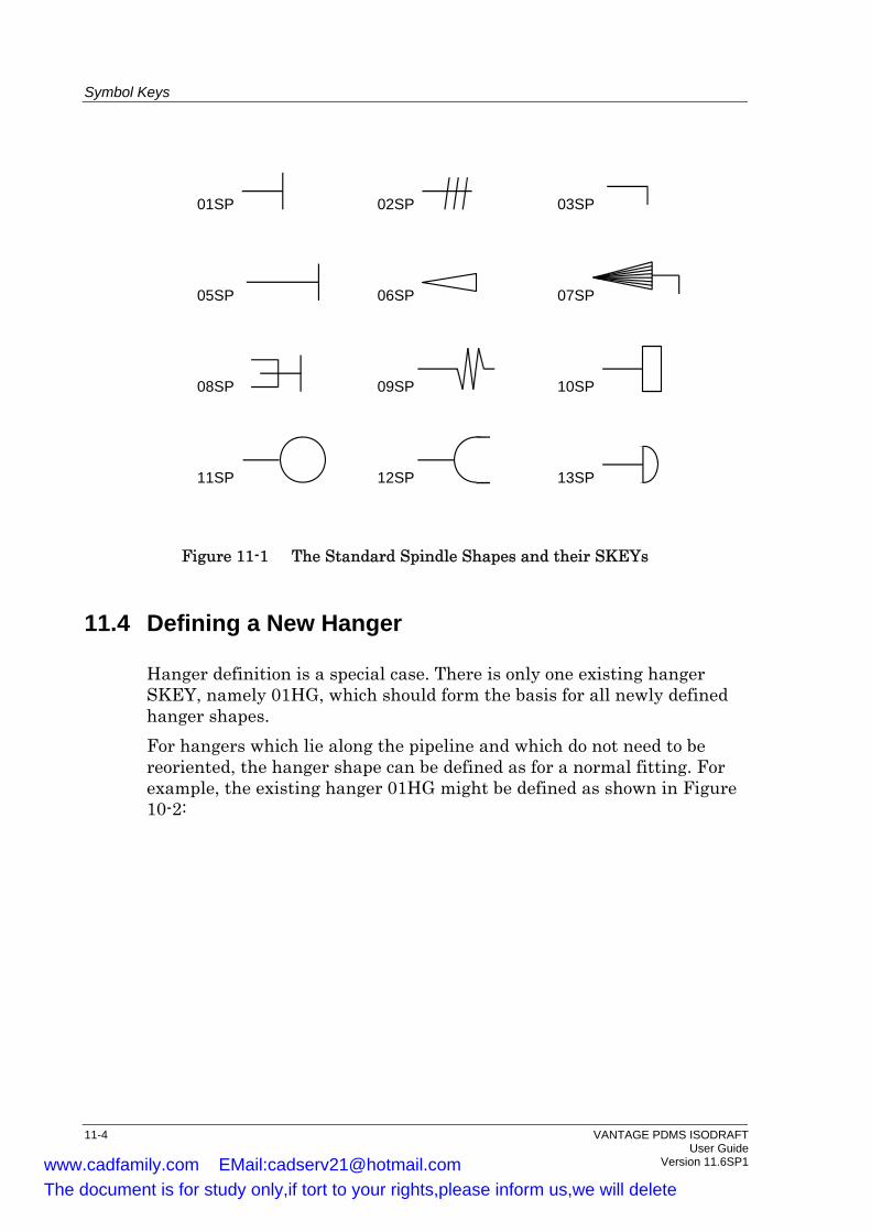
Symbol Keys
01SP 02SP 03SP
13SP
05SP 06SP 07SP
08SP 09SP 10SP
11SP 12SP
Figure 11-1 The Standard Spindle Shapes and their SKEYs
11.4 Defining a New Hanger
Hanger definition is a special case. There is only one existing hanger SKEY, namely 01HG, which should form the basis for all newly defined hanger shapes. For hangers which lie along the pipeline and which do not need to be reoriented, the hanger shape can be defined as for a normal fitting. For example, the existing hanger 01HG might be defined as shown in Figure 10-2:
11-4 VANTAGE PDMS ISODRAFT User Guide Version 11.6SP1 www.cadfamily.com EMail:[email protected]
The document is for study only,if tort to your rights,please inform us,we will delete
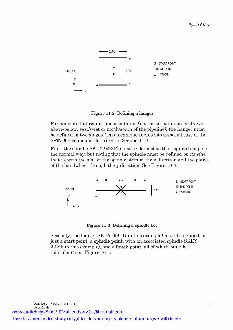
Symbol Keys
PIPE C/L 10.0
10.0
S
E
S = START POINT
E = END POINT
* = ORIGIN
*y
x
Figure 11-2 Defining a hanger
For hangers that require an orientation (i.e. those that must be drawn above/below, east/west or north/south of the pipeline), the hanger must be defined in two stages. This technique represents a special case of the SPINDLE command described in Section 11.3. First, the spindle SKEY (99SP) must be defined as the required shape in the normal way, but noting that the spindle must be defined on its side; that is, with the axis of the spindle stem in the x direction and the plane of the handwheel through the y direction. See Figure 10-3.
PIPE C/L S
E
10.0 10.0
4.0
S = START POINT
E = END POINT
* = ORIGIN
*y
x
Figure 11-3 Defining a spindle key
Secondly, the hanger SKEY (99HG in this example) must be defined as just a start point, a spindle point, with an associated spindle SKEY (99SP in this example), and a finish point, all of which must be coincident: see Figure 10-4.
VANTAGE PDMS ISODRAFT 11-5 User Guide Version 11.6SP1 www.cadfamily.com EMail:[email protected]
The document is for study only,if tort to your rights,please inform us,we will delete

Symbol Keys
PIPE C/LS = START POINT
E = END POINTy
xORIGIN
S
E
SPINDLE '99SP'
Figure 11-4 Defining a hanger with a spindle key
Note that the P3 of the ATTA gives the spindle direction of the hanger, and so it must be perpendicular to the line. The orientation of the hanger 99HG is retrieved from the database.
11.5 Pipe Components with More Than Four Connections
PCOMs and SHUs may be shown with up to six off-line legs. Flanges and filters can be shown with a single off-line leg. Off-line legs may be regarded as tapping points positioned on the piping component; for example, instrument connections on orifice flanges, vents in valve bodies, etc. SKEYs FOWN (Weld-neck orifice flange), FOSO (Slip-on orifice flange) and FI** (Inline filter) have automatic tee points. Any other symbols requiring off-line legs must be user-defined. The links between the 2D symbol representation and the 3D component model are provided by Tee points. A maximum of six tee points may be defined for each symbol. They can be defined in any order, but must be distributed on the fitting as shown:
X axis
Y axis
* *
**
*
*
e.g.
The following rules for tee point layout must be obeyed: • No tee points may be positioned on the X axis • No more than 3 tee points may be positioned above the X axis • No more than 3 tee points may be positioned below the X axis • No more than 2 tee points may be positioned on the Y axis
11-6 VANTAGE PDMS ISODRAFT User Guide Version 11.6SP1 www.cadfamily.com EMail:[email protected]
The document is for study only,if tort to your rights,please inform us,we will delete
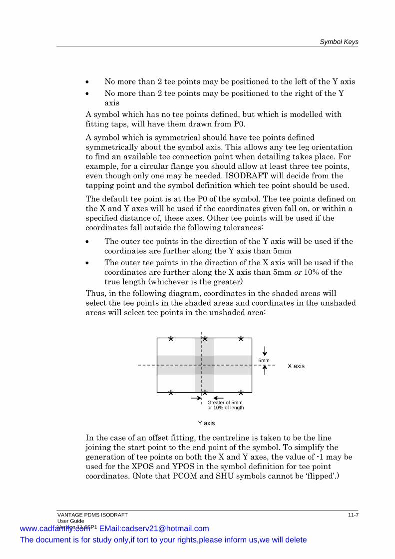
Symbol Keys
• No more than 2 tee points may be positioned to the left of the Y axis • No more than 2 tee points may be positioned to the right of the Y
axis A symbol which has no tee points defined, but which is modelled with fitting taps, will have them drawn from P0. A symbol which is symmetrical should have tee points defined symmetrically about the symbol axis. This allows any tee leg orientation to find an available tee connection point when detailing takes place. For example, for a circular flange you should allow at least three tee points, even though only one may be needed. ISODRAFT will decide from the tapping point and the symbol definition which tee point should be used. The default tee point is at the P0 of the symbol. The tee points defined on the X and Y axes will be used if the coordinates given fall on, or within a specified distance of, these axes. Other tee points will be used if the coordinates fall outside the following tolerances: • The outer tee points in the direction of the Y axis will be used if the
coordinates are further along the Y axis than 5mm • The outer tee points in the direction of the X axis will be used if the
coordinates are further along the X axis than 5mm or 10% of the true length (whichever is the greater)
Thus, in the following diagram, coordinates in the shaded areas will select the tee points in the shaded areas and coordinates in the unshaded areas will select tee points in the unshaded area:
* *
**
*
*Y axis
X axis5mm
Greater of 5mmor 10% of length
In the case of an offset fitting, the centreline is taken to be the line joining the start point to the end point of the symbol. To simplify the generation of tee points on both the X and Y axes, the value of -1 may be used for the XPOS and YPOS in the symbol definition for tee point coordinates. (Note that PCOM and SHU symbols cannot be ‘flipped’.)
VANTAGE PDMS ISODRAFT 11-7 User Guide Version 11.6SP1 www.cadfamily.com EMail:[email protected]
The document is for study only,if tort to your rights,please inform us,we will delete
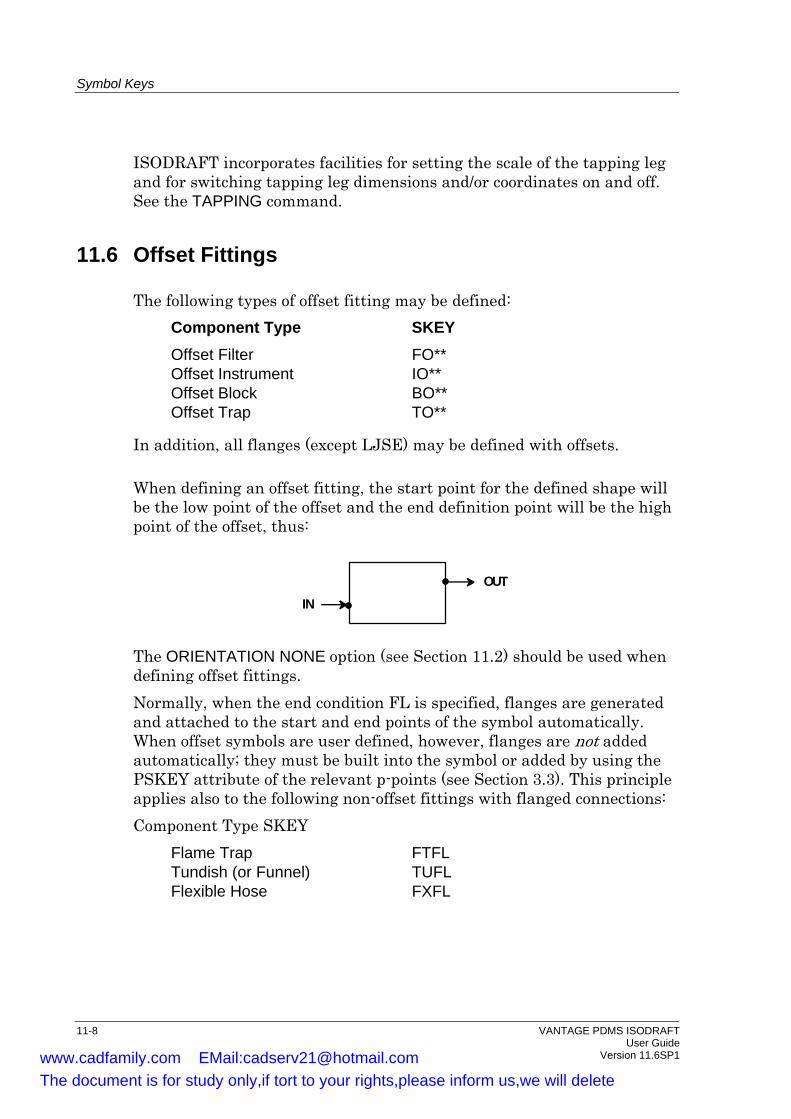
Symbol Keys
ISODRAFT incorporates facilities for setting the scale of the tapping leg and for switching tapping leg dimensions and/or coordinates on and off. See the TAPPING command.
11.6 Offset Fittings
The following types of offset fitting may be defined: Component Type SKEY Offset Filter FO** Offset Instrument IO** Offset Block BO** Offset Trap TO**
In addition, all flanges (except LJSE) may be defined with offsets.
When defining an offset fitting, the start point for the defined shape will be the low point of the offset and the end definition point will be the high point of the offset, thus:
INOUT
The ORIENTATION NONE option (see Section 11.2) should be used when defining offset fittings. Normally, when the end condition FL is specified, flanges are generated and attached to the start and end points of the symbol automatically. When offset symbols are user defined, however, flanges are not added automatically; they must be built into the symbol or added by using the PSKEY attribute of the relevant p-points (see Section 3.3). This principle applies also to the following non-offset fittings with flanged connections: Component Type SKEY
Flame Trap FTFL Tundish (or Funnel) TUFL Flexible Hose FXFL
11-8 VANTAGE PDMS ISODRAFT User Guide Version 11.6SP1 www.cadfamily.com EMail:[email protected]
The document is for study only,if tort to your rights,please inform us,we will delete
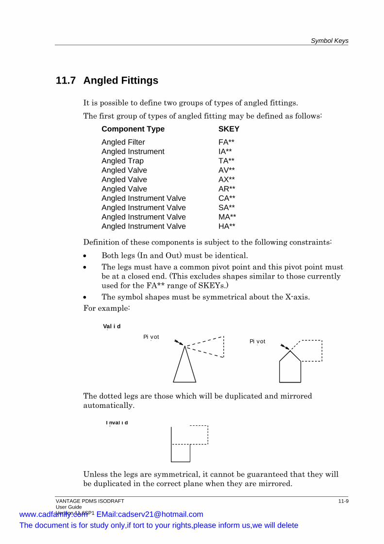
Symbol Keys
11.7 Angled Fittings
It is possible to define two groups of types of angled fittings. The first group of types of angled fitting may be defined as follows:
Component Type SKEY Angled Filter FA** Angled Instrument IA** Angled Trap TA** Angled Valve AV** Angled Valve AX** Angled Valve AR** Angled Instrument Valve CA** Angled Instrument Valve SA** Angled Instrument Valve MA** Angled Instrument Valve HA**
Definition of these components is subject to the following constraints: • Both legs (In and Out) must be identical. • The legs must have a common pivot point and this pivot point must
be at a closed end. (This excludes shapes similar to those currently used for the FA** range of SKEYs.)
• The symbol shapes must be symmetrical about the X-axis. For example:
Pi voti t
Val i dh
Pi voti t
The dotted legs are those which will be duplicated and mirrored automatically.
I nval i dh
Unless the legs are symmetrical, it cannot be guaranteed that they will be duplicated in the correct plane when they are mirrored.
VANTAGE PDMS ISODRAFT 11-9 User Guide Version 11.6SP1 www.cadfamily.com EMail:[email protected]
The document is for study only,if tort to your rights,please inform us,we will delete
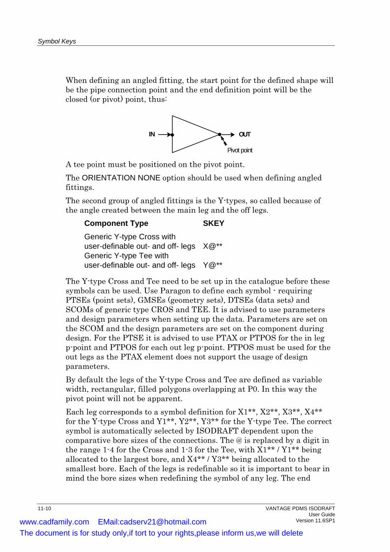
Symbol Keys
When defining an angled fitting, the start point for the defined shape will be the pipe connection point and the end definition point will be the closed (or pivot) point, thus:
OUTIN
Pivot point A tee point must be positioned on the pivot point. The ORIENTATION NONE option should be used when defining angled fittings. The second group of angled fittings is the Y-types, so called because of the angle created between the main leg and the off legs.
Component Type SKEY Generic Y-type Cross with user-definable out- and off- legs X@** Generic Y-type Tee with user-definable out- and off- legs Y@**
The Y-type Cross and Tee need to be set up in the catalogue before these symbols can be used. Use Paragon to define each symbol - requiring PTSEs (point sets), GMSEs (geometry sets), DTSEs (data sets) and SCOMs of generic type CROS and TEE. It is advised to use parameters and design parameters when setting up the data. Parameters are set on the SCOM and the design parameters are set on the component during design. For the PTSE it is advised to use PTAX or PTPOS for the in leg p-point and PTPOS for each out leg p-point. PTPOS must be used for the out legs as the PTAX element does not support the usage of design parameters. By default the legs of the Y-type Cross and Tee are defined as variable width, rectangular, filled polygons overlapping at P0. In this way the pivot point will not be apparent. Each leg corresponds to a symbol definition for X1**, X2**, X3**, X4** for the Y-type Cross and Y1**, Y2**, Y3** for the Y-type Tee. The correct symbol is automatically selected by ISODRAFT dependent upon the comparative bore sizes of the connections. The @ is replaced by a digit in the range 1-4 for the Cross and 1-3 for the Tee, with X1** / Y1** being allocated to the largest bore, and X4** / Y3** being allocated to the smallest bore. Each of the legs is redefinable so it is important to bear in mind the bore sizes when redefining the symbol of any leg. The end
11-10 VANTAGE PDMS ISODRAFT User Guide Version 11.6SP1 www.cadfamily.com EMail:[email protected]
The document is for study only,if tort to your rights,please inform us,we will delete
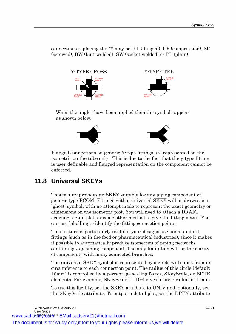
Symbol Keys
connections replacing the ** may be: FL (flanged), CP (compression), SC (screwed), BW (butt welded), SW (socket welded) or PL (plain).
Y-TYPE CROSS Y-TYPE TEE PIVOTPOINT
VARIABLEANGLE
VARIABLEANGLE
VARIABLEANGLE
VARIABLEANGLE
VARIABLEANGLE
When the angles have been applied then the symbols appear as shown below.
Flanged connections on generic Y-type fittings are represented on the isometric on the tube only. This is due to the fact that the y-type fitting is user-definable and flanged representation on the component cannot be enforced.
11.8 Universal SKEYs
This facility provides an SKEY suitable for any piping component of generic type PCOM. Fittings with a universal SKEY will be drawn as a `ghost' symbol, with no attempt made to represent the exact geometry or dimensions on the isometric plot. You will need to attach a DRAFT drawing, detail plot, or some other method to give the fitting detail. You can use labelling to identify the fitting connection points. This feature is particularly useful if your designs use non-standard fittings (such as in the food or pharmaceutical industries), since it makes it possible to automatically produce isometrics of piping networks containing any piping component. The only limitation will be the clarity of components with many connected branches. The universal SKEY symbol is represented by a circle with lines from its circumference to each connection point. The radius of this circle (default 10mm) is controlled by a percentage scaling factor, SKeyScale, on SDTE elements. For example, SKeyScale = 110% gives a circle radius of 11mm. To use this facility, set the SKEY attribute to UNIV and, optionally, set the SKeyScale attribute. To output a detail plot, set the DPFN attribute
VANTAGE PDMS ISODRAFT 11-11 User Guide Version 11.6SP1 www.cadfamily.com EMail:[email protected]
The document is for study only,if tort to your rights,please inform us,we will delete
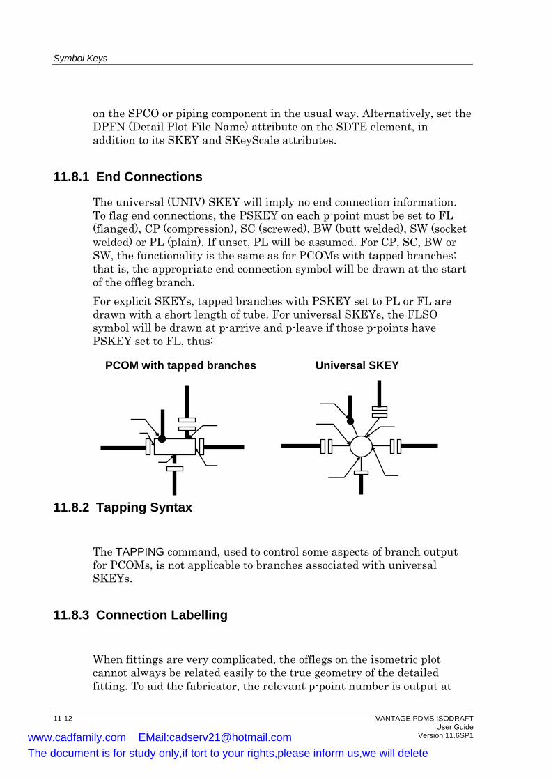
Symbol Keys
on the SPCO or piping component in the usual way. Alternatively, set the DPFN (Detail Plot File Name) attribute on the SDTE element, in addition to its SKEY and SKeyScale attributes.
11.8.1 End Connections
The universal (UNIV) SKEY will imply no end connection information. To flag end connections, the PSKEY on each p-point must be set to FL (flanged), CP (compression), SC (screwed), BW (butt welded), SW (socket welded) or PL (plain). If unset, PL will be assumed. For CP, SC, BW or SW, the functionality is the same as for PCOMs with tapped branches; that is, the appropriate end connection symbol will be drawn at the start of the offleg branch. For explicit SKEYs, tapped branches with PSKEY set to PL or FL are drawn with a short length of tube. For universal SKEYs, the FLSO symbol will be drawn at p-arrive and p-leave if those p-points have PSKEY set to FL, thus:
PCOM with tapped branches Universal SKEY
11.8.2 Tapping Syntax
The TAPPING command, used to control some aspects of branch output for PCOMs, is not applicable to branches associated with universal SKEYs.
11.8.3 Connection Labelling
When fittings are very complicated, the offlegs on the isometric plot cannot always be related easily to the true geometry of the detailed fitting. To aid the fabricator, the relevant p-point number is output at
11-12 VANTAGE PDMS ISODRAFT User Guide Version 11.6SP1 www.cadfamily.com EMail:[email protected]
The document is for study only,if tort to your rights,please inform us,we will delete
Symbol Keys
each connection point on the isometric. This number is prefixed with ATEXT 388 (default setting `P') and is drawn inside an ellipse to distinguish it from other messages. When you use a universal SKEY, you are responsible for ensuring that the detail plot has connection p-points marked in this way. If ATEXT 388 is set to blank, no messages will be output
VANTAGE PDMS ISODRAFT 11-13 User Guide Version 11.6SP1 www.cadfamily.com EMail:[email protected]
The document is for study only,if tort to your rights,please inform us,we will delete

Symbol Keys
11-14 VANTAGE PDMS ISODRAFT User Guide Version 11.6SP1 www.cadfamily.com EMail:[email protected]
The document is for study only,if tort to your rights,please inform us,we will delete

12 The ISODRAFT Transfer File Before ISODRAFT produces an isometric plot, it processes data from the Design and Catalogue databases and creates an intermediate data file (IDF). This transfer file is produced as a binary file, which is processed by ISODRAW to create the plot file: you can, however, specify that ISODRAFT will produce an ASCII copy by using the command
TRANsferfile filename where filename is the name of a file in the operating system directory. Production of the ASCII transfer file is cancelled by the command
TRANsferfilename OFF
An ASCII transfer file produced in this way can be processed by the PROCESS TRANSFERFILE filename
command to produce a plot file. The transfer file can provide a useful means for sending information to AVEVA Solutions Ltd for assistance in resolving problems associated with Product User Reports (PURs). Note: The default transfer file, /trans, will be overwritten whenever a
DETAIL or CHECK command is given. Specify a new file name if you want to keep the data.
Note that transfer files produced by versions of ISODRAFT before Version 10.3 are in binary format only, and cannot be processed by the PROCESS TRANSFERFILE command.
12.1 Preprocessing and Postprocessing Commands You can execute system commands (for customised reporting, etc.) during the transfer file processing sequences: • Preprocessing commands are system commands which are executed after
the IDF has been written and before ISODRAW has been invoked. • Postprocessing commands are system commands which are executed after
ISODRAW has finished and before control is returned to ISODRAFT.
The PREPROCESS and POSTPROCESS commands each let you define up to five numbered command strings for this purpose. The syntax is:
PREPROCESS integer1 'command string1' integer2 'command string2' ... POSTPROCESS integer1 'command string1' integer2 'command string2' ...
VANTAGE PDMS ISODRAFT 12-1 User Guide Version 11.6SP1 www.cadfamily.com EMail:[email protected]
The document is for study only,if tort to your rights,please inform us,we will delete
Index
12.2 Summary of Commands
The following commands were described in this chapter:
PROCESS TRANSFERFILE
Instructs ISODRAFT to process a transfer file.
PREPROCESS Defines up to five preprocessing system commands.
POSTPROCESS Defines up to five postprocessing system commands.
12-2 VANTAGE PDMS ISODRAFT User Guide Version 11.6SP1 www.cadfamily.com EMail:[email protected]
The document is for study only,if tort to your rights,please inform us,we will delete
Index ADD --------------------------------------------------9-6 Add list -----------------------------------------------2-9 Additional items
on material list -------------------------------5-11 Additional text --------------------------------------3-3 ALLO attribute------------------------------------6-14 Alternative itemcodes ----------------------------3-5
for bolts ----------------------------------------4-18 Alternative text -------------------------------------7-7 Arranging plots-------------------------------------2-7 Arrows
fall--------------------------------------- 9-13, 9-14 flow ---------------------------------------------9-12
ATEXT -----------------------------------------7-6, 7-8 Atexts
suppressing ------------------------------------7-8 Attached text ---------------------------------------3-2 Attachment points ---------------------------------5-2 ATTANAME---------------------------------------9-11 ATTAs------------------------------------------------5-2
comment ---------------------------------------5-3 flow-----------------------------------------------5-4 identifying -------------------------------------9-22 insulation --------------------------------------5-4 non-dimensional comment---------------5-4 split -------------------------------------- 5-4, 9-23 support -----------------------------------------5-2
Automatic numbering-----------------------------5-1 AXES-------------------------------------------------9-2 Backing sheets-------------------------------------7-3 Bend radii
standard -----------------------------------------9-9 Bend radii dimensions ---------------------------9-9 Bending table -------------------------------------7-9 BENDRADIUS -------------------------------------9-9 Bends ------------------------------------------------6-9 BITEM attribute ------------------------------------4-3 BITL attribute ---------------------------------------4-3 Blank areas on drawing sheet -----------------7-3 BLEN attribute -------------------------------------4-3 BLTAB element ------------------------------------4-1 Bolt length array -----------------------------------4-3 Bolt p<#106>point---------------------------------4-1
Bolt Point element -------------------------------- 4-1 Bolt Report --------------------------------------- 4-19
BOLTREPORT command--------------- 4-20 file ---------------------------------------------- 4-19
Bolt sets--------------------------------------------- 4-1 Bolt tables ------------------------------------------ 4-1 Bolting ----------------------------------------- 4-1, 8-7
alternative itemcodes---------------------- 4-18 bolt length array------------------------------- 4-3 bolt report------------------------------------- 4-19 BOLTREPORT command--------------- 4-20 representation --------------------------------- 4-1 tables -------------------------------------------- 4-1
BOLTING ------------------------------------------- 8-7 BOLTREPORT command------------------- 4-20 Bolts-------------------------------------------------- 6-3
alternative itemcodes---------------------- 4-18 Bolts SHOP flag----------------------------------- 4-5 Catalogue DB-------------------------------------- 3-1 Character size ----------------------------------- 9-22
on isometric ------------------------------------ 9-3 CHARSIZE ----------------------------------------- 9-3 CHECK-------------------------------------------- 2-10 Checking------------------------------------------ 2-10 CLLENGTHFILE ---------------------------------- 8-6 Commands ---------------------------------------- 1-3
abbreviations ---------------------------------- 1-3 arguments -------------------------------------- 1-4
Component descriptions ------------------------ 3-1 Component end conditions--------------------- 3-5 Continuation notes ----------------------------- 9-22 Continuation Notes ----------------------------- 9-21 Continuation symbols-------------------9-21, 9-22 CONTINUATIONSYMBOLS ----------------- 9-21 CONTWELDS command --------------------- 9-22 Coordinate
origin--------------------------------------------- 9-2 COORDINATES -------------------------- 9-2, 9-21 COORDS ------------------------------------------- 9-2 Creating a drawing ------------------------------- 2-1 Crosses --------------------------------------------- 6-7 Cut pipe lengths----------------------------------- 8-6 Cut pipe list----------------------------------------- 8-1
VANTAGE PDMS ISODRAFT index-i User Guide Version 11.6SP1 www.cadfamily.com EMail:[email protected]
The document is for study only,if tort to your rights,please inform us,we will delete

Index
Cut pipe report------------------------------------- 8-7 CUTMARKS---------------------------------------- 7-5 CUTPIPELISTFILE------------------------------- 8-7 Cutting marks -------------------------------------- 7-5 CUTTINGLIST------------------------------- 7-1, 8-6 DATE ------------------------------------------------ 7-7 Date format----------------------------------------- 7-7 Default options ---------------------------------- 2-14 Defaults
options----------------------------------------- 2-14 resetting--------------------------------------- 2-14
Defining isometric content ---------------------- 5-1 Design requirements----------------------------- 5-1 DETAIL-------------------------------2-10, 9-6, 9-17
examples ------------------------------------- 2-10 Detail flag ------------------------------------------- 9-1 Detail list ------------------------------------ 2-11, 9-6
modifying --------------------------------------- 2-8 saving on file--------------------------------- 2-10
Detail text elements ------------------------------ 3-2 Detailing------------------------------------- 2-6, 2-10 Dimensioning style ----------------------------- 9-23 Dimensions----------------------------------------- 9-7
composite ------------------------------------- 9-7 critical-------------------------------------------- 9-7 hangers ----------------------------------------- 9-9 overall------------------------------------------- 9-7 reference-------------------------------- 5-5, 9-11 rounding---------------------------------------9-10 string -------------------------------------------- 9-7 support ------------------------------------------ 9-9 truncation ------------------------------------- 9-10 units-------------------------------------------- 9-10
DIMENSIONS ------------------------------------- 9-8 Display
preserving recovering --------------------------------- 2-15
Drawing frame ------------------------------------- 7-5 Drawing issue numbering----------------------- 7-6 Drawing sheet
blank areas on--------------------------------- 7-3 Drawing sheets
numbering -------------------------------------- 9-4 DTEXT element ----------------------------- 3-2, 8-3 Dynamic Detail Areas---------------------------- 7-3 Elbows----------------------------------------------- 6-9
Elevation changes ------------------------------6-11 Elevation coordinates --------------------------9-23 Elevations -------------------------------------------9-3 ELEVATIONS --------------------------------------9-3 End coordinates
suppression ----------------------------------9-21 Equipment-----------------------------------------2-11 Equipment trim-----------------------------------2-11 EQUIPMENTNUMBERING-------------------9-18 Erection components --------------------------3-6 Erection isometrics--------------------------------7-1 Example of using ISODRAFT ----------------2-11 Fabrication components ----------------------3-6 Fabrication isometrics----------------------------7-1 Fall arrows -------------------------------- 9-13, 9-14 Fall limit ------------------------------------ 9-13, 9-14 Fall rate --------------------------------------------9-23 Falling lines ------------------------------- 9-12, 9-13
accuracy---------------------------------------9-13 Field<#106>fit weld allowance-----------------8-7 Field<#106>fit welds ---------------------------6-14 File
message ----------------------------------------2-8 output --------------------------------------------2-6
FINCH------------------------------------------------7-1 Fixed<#106>length piping --------------------6-16 Flanges ----------------------------------------------6-3
loose -------------------------------------------6-14 reducing -----------------------------------------6-5
Flow arrows------------------------- 6-1, 9-12, 9-23 FLOWARROWS---------------------------------9-12 Frame ------------------------------------------------7-5 FRAME ----------------------------------------------7-5 Gaskets ----------------------------------------------6-3 GETWORK command ------------------------2-16 INCH--------------------------------------------------7-1 In-line components--------------------------------6-1 INSTALL SETUP command ------------------2-15 INSTRUMENTS -----------------------------------8-5 Insulation ------------------------------------------9-15
ATTAs -------------------------------------------5-4 plotting -----------------------------------------9-23 start and stop points------------------------9-15
Insulation summary -------------------------------8-1 Insulation summary file --------------------------8-6
Index-ii VANTAGE PDMS ISODRAFT User Guide Version 11.6SP1 www.cadfamily.com EMail:[email protected]
The document is for study only,if tort to your rights,please inform us,we will delete
Index
INSULATIONCONTROL ----------------------9-16 Intermediate data file ---------------------------12-1 ISO----------------------------------------------------9-1 ISODRAFT
example use----------------------------------2-11 general facilities -----------------------------2-16 material needed -------------------------------3-1 output format ---------------------------------2-12
Isometric scaling -----------------------------------------9-23
Isometric plot customising-------------------------------------9-1
Isometric type --------------------------------------7-1 ISOTYPE--------------------------------------------7-1 Issue numbering-----------------------------------7-6 Item codes ---------------------------------- 8-4, 9-20
instruments -------------------------------------8-5 names as----------------------------------------8-5 specification names in -----------------------8-4 suffixes ------------------------------------------8-5
Item description------------------------------------8-3 ITEMCODE --------------------------------- 8-4, 9-20 Itemcodes
alternative---------------------------------------3-5 for bolts --------------------------------------4-18
KEYS-------------------------------------------------8-5 Layout
messages ---------------------------------------9-3 Leader lines-----------------------------------------9-3 Leg length, plotted ------------------------------9-12 Legibility ---------------------------------------------9-3 LEGLENGTH-------------------------------------9-12 Length table ----------------------------------------4-3 Line summary box --------------------------------7-6 LIST ------------------------------------------------2-16 Loose flange allowance--------------------------8-7 Loose flanges ------------------------------------6-14 LOOSEFLANGEALLOWANCE--------------6-14 LTAB element --------------------------------------4-3 MARGIN---------------------------------------------7-3 Margins ----------------------------------------------7-3 MARK ------------------------------------------7-6, 9-1 Material list------------------------------------------8-1
descriptions, changing-----------------------8-3 printed -------------------------------------------8-6
split pipes--------------------------------------- 8-8 Material List
excluding items ------------------------------- 8-4 Material take<#106>off
additional items on material list --------- 5-11 Material text element----------------------------- 3-2 MATERIALLIST ----------------------------- 8-2, 9-4 MATLISTFILENAME----------------------------- 8-6 MDB mode --------------------------------------- 2-14 MDBs
changing -------------------------------------- 2-14 Measurement units ----------------------------- 9-24 Message file---------------------------------------- 2-8
query--------------------------------------------- 2-8 Message layout ----------------------------------- 9-3 MESSAGEFILENAME--------------------------- 2-8 MILLIMETRE -------------------------------------- 7-1 MM --------------------------------------------------- 7-1 MTEXT element----------------------------- 3-2, 8-3 Multiple database ----------------------------- 2-14 Multiple databases
changing -------------------------------------- 2-14 Multiple plot file------------------------------------ 2-7 Multiple plots --------------------------------------- 7-3 North arrow----------------------------------------- 9-1 Nozzles
continuation symbols ---------------------- 9-21 NSTD attribute------------------------------------- 4-3 Numbering drawing sheets--------------------- 9-4 Olets ------------------------------------------------- 6-6 OPTIONS----------------------------------------- 2-14 OUTCOM ----------------------------------------- 9-21 Output
file ------------------------------------------------ 2-6 format------------------------------------------ 2-12 query device ----------------------------------- 2-7
OVERALLSKEWS------------------------------ 9-13 Part numbers -------------------------------------- 8-2
bolting ----------------------------------------- 4-11 PICTURESCALE --------------------------------- 9-3 Pipe end connections-------------------------- 6-10 Pipe summary ------------------------------------- 8-1 Pipe summary file--------------------------------- 8-6 Pipe support schedule--------------------- 8-1, 8-6 Plotfiles
VANTAGE PDMS ISODRAFT index-iii User Guide Version 11.6SP1 www.cadfamily.com EMail:[email protected]
The document is for study only,if tort to your rights,please inform us,we will delete
Index
multiple ------------------------------------------ 2-7 Plots, arranging ----------------------------------- 2-7 Plotted leg length ------------------------9-12, 9-23 PLOTTINGSCALE-------------------------------- 7-2 POSITION ------------------------------------------ 7-8 POSITION DETAILPLOTS --------------------- 7-4 Positioning messages --------------------------- 9-3 POSTPROCESS-------------------------------- 12-1 P-point elements ---------------------------------- 3-5 PREPROCESS---------------------------------- 12-1 PROCESS TRANSFERFILE----------------- 12-1 Project information
listing------------------------------------------- 2-16 Project numbers----------------------------------- 7-7 PROJECTNUMBER------------------------------ 7-7 QUERY-------------------------------------2-10, 2-13 Querying ------------------------------------------ 2-13 RECREATE -------------------------------------- 2-10 RECREATE command ----------------------- 2-15 Reducers-------------------------------------------- 6-8
branch connections -------------------------- 6-8 REFDIMENSIONS------------------------------ 9-11 Reference datum --------------------------------- 5-5 Reference dimensions------------5-5, 9-11, 9-23
ATTAs ----------------------------------------- 5-10 Branch Heads and Tails ------------------ 5-10 Centrelines ------------------------------------- 5-9 Errors ------------------------------------------ 5-10 Origins------------------------------------------- 5-9 piping components ------------------------- 5-10 SKEY Attributes------------------------------- 5-6
REMOVE ------------------------------------------- 9-6 Remove list----------------------------------------- 2-9 Repeatability --------------------------------------- 9-5
erasing repeatability data------------------- 9-5 REPEATABILITY --------------------------------- 9-5 RESERVE ------------------------------------------ 7-3 Revision flag --------------------------------------- 9-1 Revision table ------------------------------------ 7-9 SAVEWORK command ---------------------- 2-15 Scale ------------------------------------------------- 9-3 SETCOMPDATE-------------------------------- 10-3 Sheet layout-------------------------------------- 2-12 Sheet size ------------------------------------------ 7-2
designed drawing----------------------------- 7-2
plotted drawing --------------------------------7-2 SHOP flag-------------------------------------------3-6
bolts ----------------------------------------------4-5 tube-----------------------------------------------3-7
SIZE --------------------------------------------------7-2 Skewboxes----------------------------------------9-12
at Tees and Olets -------------------------- 9-14 suppressing ----------------------------------9-14 triangles
non<#106>standard dimensioning----9-13
overall ----------------------------------------9-13
standard dimensioning ----------------9-13
Skewed lines -------------------------------------9-12 Skewed piping -----------------------------------9-24 SKEY attribute -----------------------------3-3, 11-1 SKEYS
end conditions ---------------------------------3-5 Spatial coordinates -----------------------------9-22 SPECBREAK-------------------------------------9-16 Specification changes------------------ 6-15, 9-16 Spindles ---------------------------------------------6-1 SPLIT-------------------------------------------------9-4 Split pipes
material list--------------------------------------8-8 Splits in tube----------------------------------------9-5 Splitting drawings -------------------------------9-24 Splitting pipes --------------------------------------9-4 Splitting tubes ------------------------------------9-24 Spool breaks
adding--------------------------------------------5-1 Spool isometrics -----------------------------------7-1 Spooling ---------------------------------------------5-1 Stacking plots --------------------------------------2-7 STACKINGARRANGEMENT ------------------7-3 Stamp ----------------------------------------------10-3 Standout distance -------------------------9-9, 9-11 Starting up ISODRAFT---------------------------2-2 Status
of system--------------------------------------2-16 of user -----------------------------------------2-16
Structural elements -----------------------------2-11 SUPPORTFILENAME----------------------------8-6 Supports
attachment point names-------------------9-11 SUPPORTS ----------------------------------------9-9
Index-iv VANTAGE PDMS ISODRAFT User Guide Version 11.6SP1 www.cadfamily.com EMail:[email protected]
The document is for study only,if tort to your rights,please inform us,we will delete
Index
Suppressing text-----------------------------------7-8 Symbol key ----------------------------------------3-3 Symbol keys -------------------------------- 3-3, 11-1
angled fittings -----------------------11-9, 11-10 creating new----------------------------------11-1 defining attributes ---------------------------11-2 maximum number---------------------------11-1 offset fittings----------------------------------11-8 spindles --------------------------------------11-3 universal------------------------------------- 11-12
System isometric ------------------------ 2-11, 9-17 System status ------------------------------------2-16 System table ------------------------------------7-10 Tag numbers ---------------------------------------6-2 Tags ----------------------------------------------- 9-20
boxes-------------------------------------------9-21 Tapping legs
coordinates -----------------------------------11-8 dimensions -----------------------------------11-7 scale--------------------------------------------11-7
Tees --------------------------------------------------6-6 Text
user<#106>positioned -----------------------7-8 Text elements -------------------------------------3-1 Text size
on isometric drawing -------------------------9-3 Title block -------------------------------------------7-6
additional text ----------------------------------7-6 suppressing ------------------------------------7-6
TITLEBLOCK---------------------------------------7-6 TOLERANCE-------------------------------------9-12 Tolerancing ---------------------------------------9-12 Tracing---------------------------------------------9-15 TRACINGCONTROL---------------------------9-16 Transfer file ---------------------------------------12-1 TRANSFERFILE --------------------------------12-1 TRUNCATE---------------------------------------9-11 Tube
SHOP flag -------------------------------------- 3-7 TUBESPLITS -------------------------------------- 9-5 UNDERLAYPLOTFILE -------------------------- 7-3 Units
input---------------------------------------------- 7-1 output------------------------------------------ 9-10
UNITS --------------------------------------------- 9-10 User defined tables--- 7-9, See the POSITION command
bends ------------------------------------------- 7-9 revision----------------------------------------- 7-9 system---------------------------------------- 7-10 welds -------------------------------------------- 7-9
User status --------------------------------------- 2-16 Using defaults ------------------------------------- 2-1 Valve spindles ------------------------------------- 6-1 Valves ----------------------------------------------- 6-1
3<#106>way ----------------------------------- 6-3 4<#106>way ----------------------------------- 6-3 angled ------------------------------------------- 6-3
View direction-------------------------------------- 9-1 Wafer fittings--------------------------------------- 6-5 Wastage allowance ------------------------------ 8-7 WASTAGE AREA -------------------------------- 8-7 Weld table ----------------------------------------- 7-9 WELDID------------------------------------------- 9-20 WELDNUMBERS------------------------------- 9-19 Welds ---------------------------------------------- 9-19
field<#106>fit -------------------------------- 6-14 identification --------------------------------- 9-24 names ----------------------------------------- 9-20 numbering -----------------------------9-19, 9-24 symbols --------------------------------------- 9-19 table of numbers---------------------------- 9-19 types displayed ----------------------------- 9-24
WELDTYPE-------------------------------------- 9-19 ZEROLENGTHSKEWS ----------------------- 9-14
VANTAGE PDMS ISODRAFT index-v User Guide Version 11.6SP1 www.cadfamily.com EMail:[email protected]
The document is for study only,if tort to your rights,please inform us,we will delete


![ISODRAFT Reference Manual [EDocFind.info]](https://img.pdfslide.us/doc/110x75/5531ca125503465e598b4b86/isodraft-reference-manual-edocfindinfo.jpg)