Embed Size (px)
Citation preview
14401 Keil Road NE, Aurora, Oregon, USA 97002
PHONE 503-678-6545 FAX 503-678-6560 www.vansaircraft.com [email protected] Service Letters and Bulletins: www.vansaircraft.com/public/service.htm
REVISION DESCRIPTION: Since all the KAI pages regarding W&B and the Installed Equipment list are similar, only a general description of the two types of changes made to various sections is provided below. These changes resulted from relocating the Weight and Balance Worksheet and the Installed Equipment List. a. The Installed Equipment List was moved to the Maintenance Manual from the POH. b. The Weight and Balance Worksheet and W&B-2 (the blank page that followed) were moved to the Maintenance Manual (Rev 9) from the Production Acceptance Procedure. The "WEIGHT AND BALANCE RECORD" page was page W&B-2 of the RV-12 Production Acceptance Procedures. Example: Following is an example of how this change affected Section 44A Skyview Autopilot Servos. "Step 6: In the RV-12 Maintenance Manual (MM) "INSTALLED EQUIPMENT LIST" table, mark the "DYNON AUTOPILOT SERVO" as installed in the "INSTALLED" column. Enter 4.6 lb for "Weight" , 101.5 in for "Location/Arm" and 467 in-lb "Moment" onto the same line as "DYNON AUTOPILOT SERVO". NOTE: The remaining steps on this page are only applicable to a flying aircraft. Step 7: In the RV-12 Pilot Operating Handbook (POH) "YOUR AIRPLANE" table, enter the new total values for the arm, weight, and moment of the installed equipment. Step 8: In the RV-12 POH "YOUR AIRPLANE" table, recalculate and enter new values for the Empty Weight, Empty Moment, and Empty Arm. Step 9: Make an entry, as calculated in the previous step, on the WEIGHT AND BALANCE RECORD page of the RV-12 Maintenance Manual as follows: As of this date: ___/___/___" was "Step 6: On Page 4-2 SkyView and 4-4 of the RV-12 Pilot Operating Handbook: Enter the text "AUTOPILOT" onto a blank line under the "ITEM" column in both tables. Enter 4.6 lb for "Weight" , 101.5 in for "Location/Arm" and 467 in-lb "Moment" onto the same line as "AUTOPILOT" in both tables. Recalculate and enter new values for the Empty Weight, Empty Moment and Empty Arm on Page 4-4 of the POH. Step 7: Make an entry on page W&B-2 of the RV-12 Production Acceptance Procedures as follows: As of this date: ___/___/___"

14401 Keil Road NE, Aurora, Oregon, USA 97002
PHONE 503-678-6545 FAX 503-678-6560 www.vansaircraft.com [email protected] Service Letters and Bulletins: www.vansaircraft.com/public/service.htm
The changes described above were applied to the following pages. The updated Rev level is listed: 40-15 (Rev 2) 43-11 (Rev 2) 43B-08 (Rev 2) 43C-07 (Rev 1) 44A-05 (Rev 4) 44B-10 (Rev 1) 53-12 (Rev 3) 53B-06 (Rev 1) 58-06 (Rev 1) 61-08 (Rev 1)
Additional changes were also made and are described below in the usual manner. Page 44A-04 REV 3: Add “(WITH FLAPS UP AND WITH FLAPS DOWN)” to the WARNING. Page: 44B-03 REV 1: Add: "Step 4: Insert the bolt that will attach the Pitch Servo Pushrod Assembly to the arm of the Garmin GSA 28 Autopilot Servo. See Figure 2." Repaginate remaining steps. Page 44B-06 REV 1: Add “(WITH FLAPS UP AND WITH FLAPS DOWN)” to the WARNING. Page 44B-07 REV 2: Show additional cut lines for GMC 307 in Figure 2. Add “(GMC 305)” after hardware callouts in Figure 2. Page: 53-10 REV 2: Deleted fuse amperage values shown in Figure 2, except for GPS ADSB, "2" AMP. Page: 53B-05 REV 1: Deleted AMP values from fuses in Figure 2, except for GPS ADSB, "2" AMP.
PAGEREVISION:DATE:
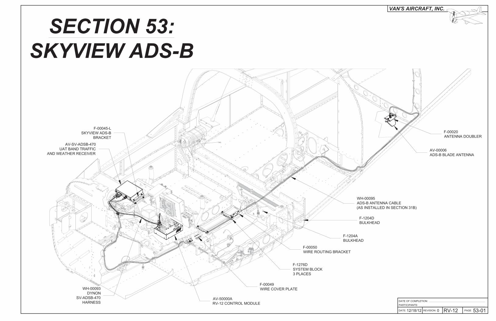
VAN'S AIRCRAFT, INC.
SECTION 53:
SKYVIEW ADS-B
PARTICIPANTS:
12/18/12 0 RV-12
DATE OF COMPLETION:
53-01
WH-00095
ADS-B ANTENNA CABLE
(AS INSTALLED IN SECTION 31B)
AV-00006
ADS-B BLADE ANTENNA
F-00020
ANTENNA DOUBLER
WH-00093
DYNON
SV-ADSB-470
HARNESS
AV-SV-ADSB-470
UAT BAND TRAFFIC
AND WEATHER RECEIVER
F-00045-L
SKYVIEW ADS-B
BRACKET
AV-50000A
RV-12 CONTROL MODULE
F-00049
WIRE COVER PLATE
F-00050
WIRE ROUTING BRACKET
F-1276D
SYSTEM BLOCK
3 PLACES
F-1204A
BULKHEAD
F-1204D
BULKHEAD
PAGE REVISION: DATE:
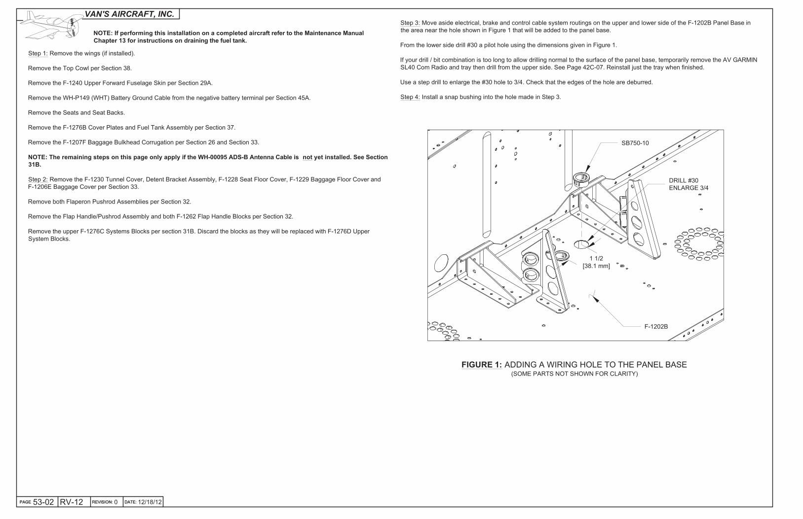
VAN'S AIRCRAFT, INC.Step 3: Move aside electrical, brake and control cable system routings on the upper and lower side of the F-1202B Panel Base in
the area near the hole shown in Figure 1 that will be added to the panel base.
From the lower side drill #30 a pilot hole using the dimensions given in Figure 1.
If your drill / bit combination is too long to allow drilling normal to the surface of the panel base, temporarily remove the AV GARMIN
SL40 Com Radio and tray then drill from the upper side. See Page 42C-07. Reinstall just the tray when finished.
Use a step drill to enlarge the #30 hole to 3/4. Check that the edges of the hole are deburred.
Step 4: Install a snap bushing into the hole made in Step 3.
12/18/12PAGE 53-02 RV-12 REVISION: 0 DATE:
Step 1: Remove the wings (if installed).
Remove the Top Cowl per Section 38.
Remove the F-1240 Upper Forward Fuselage Skin per Section 29A.
Remove the WH-P149 (WHT) Battery Ground Cable from the negative battery terminal per Section 45A.
Remove the Seats and Seat Backs.
Remove the F-1276B Cover Plates and Fuel Tank Assembly per Section 37.
Remove the F-1207F Baggage Bulkhead Corrugation per Section 26 and Section 33.
NOTE: The remaining steps on this page only apply if the WH-00095 ADS-B Antenna Cable is not yet installed. See Section
31B.
Step 2: Remove the F-1230 Tunnel Cover, Detent Bracket Assembly, F-1228 Seat Floor Cover, F-1229 Baggage Floor Cover and
F-1206E Baggage Cover per Section 33.
Remove both Flaperon Pushrod Assemblies per Section 32.
Remove the Flap Handle/Pushrod Assembly and both F-1262 Flap Handle Blocks per Section 32.
Remove the upper F-1276C Systems Blocks per section 31B. Discard the blocks as they will be replaced with F-1276D Upper
System Blocks.
FIGURE 1: ADDING A WIRING HOLE TO THE PANEL BASE(SOME PARTS NOT SHOWN FOR CLARITY)
F-1202B
SB750-10
DRILL #30
ENLARGE 3/4
1 1/2
[38.1 mm]
NOTE: If performing this installation on a completed aircraft refer to the Maintenance Manual
Chapter 13 for instructions on draining the fuel tank.

PAGEREVISION:DATE:
VAN'S AIRCRAFT, INC.NOTE: Steps 1 and 2 on this page only apply if the WH-00095 ADS-B Antenna Cable is not yet installed.
Step 1: Drill 3/4 and deburr a new wiring hole in the F-1204A Bulkhead as shown in Figure 1.
Install a snap bushing in the hole as shown in Figure 1.
DATE: 53-03107/08/13 REVISION: RV-12 PAGE
FIGURE 1: MODIFYING F-1204A(FRONT CUTAWAY VIEW)
Step 2: Drill 3/4 and deburr a new wiring hole in the F-1204D Bulkhead as shown in Figure 2.
Install a snap bushing in the hole as shown in Figure 2.
FIGURE 2: MODIFYING F-1204D(FRONT CUTAWAY VIEW)
DRILL 3/4
INSERT SB750-10
1/4 [6.3 mm]1 [25.4 mm]
DRILL 3/4
INSTALL SB750-10
FIGURE 3: SEPARATING THE
ADS-B BRACKETS
NOTE: Skip Step 3 and Step 4 if installing the Garmin GTR-200.
Step 3: Label and separate the F-00045-L & -R SkyView ADS-B Brackets as shown in Figure 3 by
removing the hatched areas.
Deburr the edges of both parts.
Step 4: Machine countersink the nutplate attach holes in the F-00045-L & -R SkyView ADS-B Brackets as shown in Figure 3.
Rivet nutplates to the brackets using the hardware called out in Figure 3.
Step 5: Separate the F-00020 Antenna Doublers by removing the hatched area shown in Figure 4. Discard one part.
Deburr the edges of the remaining doubler.
4X
F-00045-R
F-00045-L
REMOVE
HATCHED
AREAS
F-00020,
2 PLACES
REMOVE
HATCHED
AREAS
FIGURE 4: SEPARATING THE
ANTENNA DOUBLERS
K1000-08
2X AN426AD3-3.5
1 [25.4 mm]
PAGE REVISION: DATE:
VAN'S AIRCRAFT, INC.
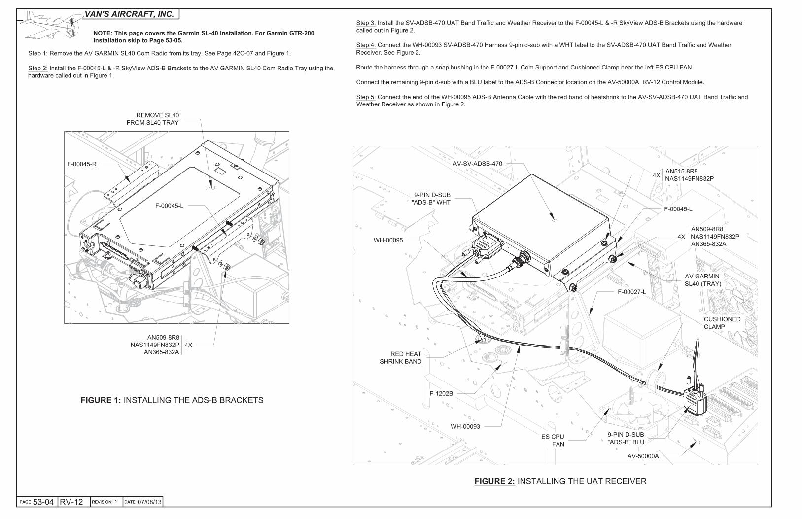
Step 1: Remove the AV GARMIN SL40 Com Radio from its tray. See Page 42C-07 and Figure 1.
Step 2: Install the F-00045-L & -R SkyView ADS-B Brackets to the AV GARMIN SL40 Com Radio Tray using the
hardware called out in Figure 1.
07/08/13PAGE 53-04 RV-12 REVISION: 1 DATE:
FIGURE 1: INSTALLING THE ADS-B BRACKETS
F-00045-R
F-00045-L
4X
AN509-8R8
NAS1149FN832P
AN365-832A
REMOVE SL40
FROM SL40 TRAY
FIGURE 2: INSTALLING THE UAT RECEIVER
Step 3: Install the SV-ADSB-470 UAT Band Traffic and Weather Receiver to the F-00045-L & -R SkyView ADS-B Brackets using the hardware
called out in Figure 2.
Step 4: Connect the WH-00093 SV-ADSB-470 Harness 9-pin d-sub with a WHT label to the SV-ADSB-470 UAT Band Traffic and Weather
Receiver. See Figure 2.
Route the harness through a snap bushing in the F-00027-L Com Support and Cushioned Clamp near the left ES CPU FAN.
Connect the remaining 9-pin d-sub with a BLU label to the ADS-B Connector location on the AV-50000A RV-12 Control Module.
Step 5: Connect the end of the WH-00095 ADS-B Antenna Cable with the red band of heatshrink to the AV-SV-ADSB-470 UAT Band Traffic and
Weather Receiver as shown in Figure 2.
9-PIN D-SUB
"ADS-B" WHT
WH-00095
WH-00093
AV-SV-ADSB-470
4X
4X
AV GARMIN
SL40 (TRAY)
F-00027-L
CUSHIONED
CLAMP
9-PIN D-SUB
"ADS-B" BLUES CPU
FAN
F-00045-L
AV-50000A
AN515-8R8
NAS1149FN832P
AN509-8R8
NAS1149FN832P
AN365-832A
RED HEAT
SHRINK BAND
F-1202B
NOTE: This page covers the Garmin SL-40 installation. For Garmin GTR-200
installation skip to Page 53-05.

PAGEREVISION:DATE:
VAN'S AIRCRAFT, INC.
DATE: 53-05107/08/13 REVISION: RV-12 PAGE
FIGURE 1: SEPARATING THE
ADS-B BRACKETS
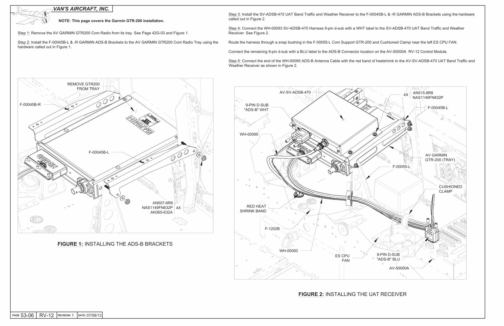
NOTE: This page covers the Garmin GTR-200 installation. For Garmin SL-40 installation skip to Page 53-07.
Step 1: Label and separate the F-00045B-L & -R Garmin ADS-B Brackets as shown in Figure 1 by removing the hatched areas.
Deburr the edges of both parts.
Step 2: Machine countersink the nutplate attach holes in the F-00045B-L & -R Garmin ADS-B Brackets as shown in Figure 1.
Rivet nutplates to the brackets using the hardware called out in Figure 1.
4X
F-00045B-R
F-00045B-L
REMOVE
HATCHED
AREAS
K1000-08
2X AN426AD3-3.5
PAGE REVISION: DATE:
VAN'S AIRCRAFT, INC.
Step 1: Remove the AV GARMIN GTR200 Com Radio from its tray. See Page 42G-03 and Figure 1.
Step 2: Install the F-00045B-L & -R GARMIN ADS-B Brackets to the AV GARMIN GTR200 Com Radio Tray using the
hardware called out in Figure 1.
07/08/13PAGE 53-06 RV-12 REVISION: 1 DATE:
FIGURE 1: INSTALLING THE ADS-B BRACKETS
F-00045B-R
F-00045B-L
4X
AN507-6R8
NAS1149FN632P
AN365-632A
REMOVE GTR200
FROM TRAY
FIGURE 2: INSTALLING THE UAT RECEIVER
Step 3: Install the SV-ADSB-470 UAT Band Traffic and Weather Receiver to the F-00045B-L & -R GARMIN ADS-B Brackets using the hardware
called out in Figure 2.
Step 4: Connect the WH-00093 SV-ADSB-470 Harness 9-pin d-sub with a WHT label to the SV-ADSB-470 UAT Band Traffic and Weather
Receiver. See Figure 2.
Route the harness through a snap bushing in the F-00055-L Com Support GTR-200 and Cushioned Clamp near the left ES CPU FAN.
Connect the remaining 9-pin d-sub with a BLU label to the ADS-B Connector location on the AV-50000A RV-12 Control Module.
Step 5: Connect the end of the WH-00095 ADS-B Antenna Cable with the red band of heatshrink to the AV-SV-ADSB-470 UAT Band Traffic and
Weather Receiver as shown in Figure 2.
9-PIN D-SUB
"ADS-B" WHT
WH-00095
WH-00093
AV-SV-ADSB-4704X
AV GARMIN
GTR-200 (TRAY)
F-00055-L
CUSHIONED
CLAMP
9-PIN D-SUB
"ADS-B" BLUES CPU
FAN
F-00045B-L
AV-50000A
AN515-8R8
NAS1149FN832P
RED HEAT
SHRINK BAND
F-1202B
NOTE: This page covers the Garmin GTR-200 installation.
PAGEREVISION:DATE:
VAN'S AIRCRAFT, INC.
DATE: 53-07107/08/13 REVISION: RV-12 PAGE
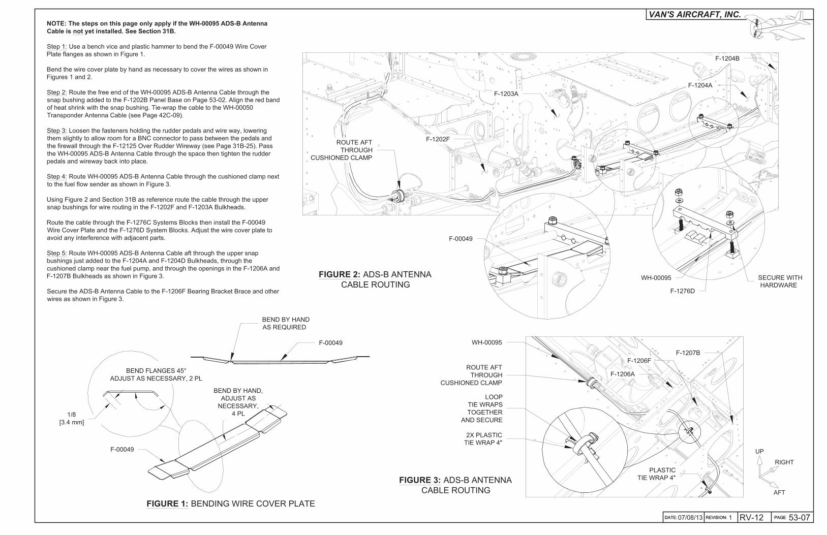
NOTE: The steps on this page only apply if the WH-00095 ADS-B Antenna
Cable is not yet installed. See Section 31B.
Step 1: Use a bench vice and plastic hammer to bend the F-00049 Wire Cover
Plate flanges as shown in Figure 1.
Bend the wire cover plate by hand as necessary to cover the wires as shown in
Figures 1 and 2.
Step 2: Route the free end of the WH-00095 ADS-B Antenna Cable through the
snap bushing added to the F-1202B Panel Base on Page 53-02. Align the red band
of heat shrink with the snap bushing. Tie-wrap the cable to the WH-00050
Transponder Antenna Cable (see Page 42C-09).
Step 3: Loosen the fasteners holding the rudder pedals and wire way, lowering
them slightly to allow room for a BNC connector to pass between the pedals and
the firewall through the F-12125 Over Rudder Wireway (see Page 31B-25). Pass
the WH-00095 ADS-B Antenna Cable through the space then tighten the rudder
pedals and wireway back into place.
Step 4: Route WH-00095 ADS-B Antenna Cable through the cushioned clamp next
to the fuel flow sender as shown in Figure 3.
Using Figure 2 and Section 31B as reference route the cable through the upper
snap bushings for wire routing in the F-1202F and F-1203A Bulkheads.
Route the cable through the F-1276C Systems Blocks then install the F-00049
Wire Cover Plate and the F-1276D System Blocks. Adjust the wire cover plate to
avoid any interference with adjacent parts.
Step 5: Route WH-00095 ADS-B Antenna Cable aft through the upper snap
bushings just added to the F-1204A and F-1204D Bulkheads, through the
cushioned clamp near the fuel pump, and through the openings in the F-1206A and
F-1207B Bulkheads as shown in Figure 3.
Secure the ADS-B Antenna Cable to the F-1206F Bearing Bracket Brace and other
wires as shown in Figure 3.
WH-00095 SECURE WITH
HARDWAREF-1276D
F-00049
FIGURE 2: ADS-B ANTENNA
CABLE ROUTING
ROUTE AFT
THROUGH
CUSHIONED CLAMP
F-1202F
F-1203A
F-1204A
F-1204B
FIGURE 3: ADS-B ANTENNA
CABLE ROUTING
BEND FLANGES 45°
ADJUST AS NECESSARY, 2 PL
F-00049
BEND BY HAND,
ADJUST AS
NECESSARY,
4 PL1/8
[3.4 mm]
FIGURE 1: BENDING WIRE COVER PLATE
LOOP
TIE WRAPS
TOGETHER
AND SECURE
WH-00095
ROUTE AFT
THROUGH
CUSHIONED CLAMP
F-1206A
F-1206F
2X PLASTIC
TIE WRAP 4"
F-1207B
AFT
RIGHT
UP
PLASTIC
TIE WRAP 4"
F-00049
BEND BY HAND
AS REQUIRED

PAGE REVISION: DATE:
VAN'S AIRCRAFT, INC.
07/08/13PAGE 53-08 RV-12 REVISION: 1 DATE:
FIGURE 3: INSTALLING THE
GUIDE BRACKET
NOTE: The steps on this page only apply if the WH-00095
ADS-B Antenna Cable is not yet installed. See Section 31B.
Step 1: Remove the hatched area as shown in Figure 1 to leave
one F-1016HX Guide Bracket.
Step 2: Position F-1016HX Guide Bracket on the inboard flange
of the F-1207D-L Baggage Bulkhead Channel with the forward
edge of the bracket even with the start of the bend in the flange of
the channel. See Figure 2.
Position guide bracket vertically approximately as shown in Figure
2 (exact position is not critical).
Step 3: Use a 12" long #30 drill to match-drill #30 both holes in
the F-1016HX Guide Bracket into the flange of the F-1207D-L
Baggage Bulkhead Channel.
Step 4: Remove the F-1016HX Guide Bracket.
Deburr the holes in the bracket and channel.
Step 5: Rivet F-1016HX Guide Bracket to F-1207D-L Baggage Bulkhead Channel per the callouts in Figure 3.
Step 6: Route the WH-00095 ADS-B Antenna Cable through the hole in the bracket. Make a slit in the snap bushing, wrap it around
the ADS-B antenna cable, and insert in the guide bracket as shown in Figure 3.
F-1016HXFIGURE 1: SPLITTING APART
THE GUIDE BRACKETS
SB625-8
(SPLIT BUSHING)
LP4-3,
2 PLACES
AFT
INBD
UP
AFT
INBD
UP
F-1207D-L
F-1016HX
F-1207D-L
FIGURE 2: MATCH-DRILLING
THE GUIDE BRACKET
FORWARD EDGE OF PART
EVEN WITH START OF BEND
WH-00095
PAGEREVISION:DATE:
VAN'S AIRCRAFT, INC.
DATE: 53-09107/08/13 REVISION: RV-12 PAGE
Step 4: Install the AV-00006 Blade ADS-B Antenna to the
F-00020 Antenna Doubler and F-1282-L Bottom Left Skin using the
instructions and hardware supplied with the antenna. See Figure 3.
FIGURE 1: INSTALLING THE
ANTENNA DOUBLER
Step 1: Position the F-00020 Antenna Doubler on the F-1282-L Bottom Left Skin as shown in Figure 1.
Match-Drill #30 and cleco the four .098 holes in the doubler into the skin.
Match-Drill 3/16 the two holes in the doubler into the skin.
Drill #30 the center of the middle hole as shown in Figure 1. Final-Drill 9/16 the center hole in the skin.
Remove the doubler and deburr the holes in both the doubler and skin.
Step 2: Rivet the F-00020 Antenna Doubler to the F-1282-L Bottom Left Skin using the rivets called out in Figure 1.
FIGURE 3: INSTALLING THE UAT ANTENNA(BOTTOM SKIN SHOWN TRANSPARENT)
FIGURE 4: ROUTING THE ANTENNA CABLE
PLASTIC TIE
WRAP 4"
WH-00095
F-00020
ADD TIE WRAPS
AS REQUIRED SO
WH-00095 DOESN'T
CHAFE ON SKIN
F-00020
F-1282-L
F-1208
ALIGN AFT
EDGE OF
F-00020 WITH
FWD EDGE OF
F-1208 FLANGE
F-00020
AV-00006
2X
MATCH-DRILL #30
LP4-3
4 PLACES
MATCH-DRILL #12
2 PLACES
DRILL #30 CENTERED
BETWEEN TWO MIDDLE
HOLES ENLARGE TO 9/16
AN365-832A
MS35335-31
CENTER
DOUBLER
BETWEEN
THESE HOLES
F-1208
FIGURE 2: FUSELAGE FRAME TIE WRAP LOCATIONS
Step 3: Drill #30 three holes in the
web of the F-1208 Fuselage Frame
for tie wraps (if not already punched
in part). See Figures 2 and 4.
Deburr the three holes just drilled.
F-1208
1 1/2
[38.1 mm]
TYP
1/4
[6.4 mm]
TYP
Step 5: Connect the WH-00095 ADS-B Antenna Cable to the AV-00006 Blade ADS-B Antenna as shown in Figure 4.
Tie-wrap the cable to the F-1208 Fuselage Frame as shown in Figure 4.

PAGE REVISION: DATE:
VAN'S AIRCRAFT, INC.
05/24/16PAGE 53-10 RV-12 REVISION: 2 DATE:
FIGURE 2: ADDING TO THE FUSE HOLDER
Step 2: Install a second fuse in the F-12123 Fuse Holder Assembly pertaining to the same fuse value shown in Figure 2.
FIGURE 1: INSTALLING FUSE
Step 1: Install fuse called out in the AV-50001 Power & Switch Module as shown in Figure 1.
AV-50001
ES 00202
MAP BOX DOOR ATC FUSE
(MATCH VALUES SHOWN IN FIGURE 1)
F-12123
# # # # # # # # # # #
PAGEREVISION:DATE:
VAN'S AIRCRAFT, INC.
DATE: 53-11007/08/13 REVISION: RV-12 PAGE
Step 2: Secure the Flap
Handle/ Pushrod Assembly
and F-00050 Wire Routing
Bracket to the inboard
F-1215-L & -R Seat Ribs as
shown in Figure 2. Use the
F-1262 Flap Handle Blocks
and the hardware called out in
Section 32.
FIGURE 2: INSTALLING
THE FLAP HANDLE/ PUSHROD ASSEMBLY
F-1262
2 PLACES
FLAP HANDLE/ PUSHROD
ASSEMBLY
F-1215-L
F-1215-RF-00050
Step 3: Attach the Flaperon Pushrod Assemblies per Section 32,
and install the F-1230 Tunnel Cover, Detent Bracket Assembly,
and F-1206E Baggage Cover per Section 33.
Step 4: Re-Install the F-1207F Baggage Bulkhead Corrugation per Section 33.
Re-Install the F-1276B Cover Plates and Fuel Tank Assembly per Section 37.
Re-Install the Seats and Seat Backs per Section 33 and Section 26.
Connect the WH-P149 (WHT) Battery Ground Cable to the negative battery terminal per Section 45A.
Install the F-1240 Upper Forward Fuselage Skin per Section 29A.
Attach the Top Cowl per Section 38.
FIGURE 1: BRACKET
MODIFICATION
NOTE: The remaining steps on
this page apply only if the
WH-00049 ADS-B Antenna
Cable was not previously
installed. See Section 31B.
Step 1: The bend near the radius
cut on the F-00050 Wire Routing
Bracket may need to be adjusted
using a vice and a plastic
hammer or with a hand seamer
as called out in Figure 1. This
bend affects the placement of
the attachment holes.
Use a bench vice or hand
seamer to bend up the Wire
Routing Bracket flanges as
shown in Figure 1.
BEND 25°, ADJUST
AS NECESSARY,
2 PL
1/2 [12.7 mm]
F-00050
ADJUST
BY HAND
PAGE REVISION: DATE:
VAN'S AIRCRAFT, INC.
05/24/1653-12 RV-12 REVISION:REVISION: 3 DATE:DATE:
Step 1: Download and install the latest firmware and settings file from the downloads page of the Van's Aircraft web site.
Download and install from the same location the RV-12 ADS-B pre-sets file.
Step 2 (Updating Transponder Firmware): This step applies if the aircraft already received an avionics kit before October 2012 orhas a transponder with a firmware version before 2.02.
When updating the Transponder Firmware, you must add an updated TSO label to the Transponder box to maintain airworthystatus. Go to the SkyView support section of the Dynon web site and download the label document appropriate for yourtransponder model. Follow the instructions contained in that document for installing the label.
Enter the main Setup Menu screen (hold buttons 7 & 8)
Select transponder Setup
If transponder status line is colored white, the transponder is up to date and you can move on to configuring the serial port for theADSB-470. If the status line is colored yellow, the firmware needs to be updated.
To update the transponder firmware, toggle right to highlight the transponder status line.
Press button 8 to load the firmware.
Press Yes to confirm that you have the appropriate transponder label available for installation.
When the load process is complete, a Power Cycle status window will be displayed. Turn the avionics switch off and then back on,to recycle the transponder.
Return to the main Setup Menu screen.
Scroll down to Transponder Setup.
Confirm that the Transponder status line is now displayed white (indicates firmware correctly loaded and is up to date).
Step 3: Enter the main Setup Menu Screen.
Scroll down to Local Display Setup.
Toggle right, and then scroll down to Serial Port Setup
Toggle right, and then scroll down to Serial Port 2 Setup
Verify that the Tx and Rx counters on the status page are changing, to confirm that serial data is being transmitted and received toand from the ADSB unit, and then press exit to leave the Setup Menu.
Remaining information on Setup and functionality of the SV-ADSB-470 UAT Band Traffic and Weather Receiver may be foundthrough the Dynon web site.
Step 4: Download the latest RV-12 overall electrical schematic from the Van's Aircraft web site.
NOTE: Any weight and balance information recorded for the aircraft must be updated. Depending on the state of your kitsome steps may not be applicable.
Step 5: In the RV-12 Maintenance Manual (MM) "INSTALLED EQUIPMENT LIST" table, add "ADS-B" to the "ITEM" column. On thesame line add a checkmark to the "INSTALLED" column.
Enter 1.89 lb for "Weight", 76.07 in for "Location/Arm" and 143.78 in-lb "Moment" onto the same line as "ADS-B".
NOTE: Steps 6-8 on this page are only applicable if a final weight and balance as specified in the PAP has been completed.
Step 6: In the RV-12 Pilot Operating Handbook (POH) "YOUR AIRPLANE" table, enter the new total values for the arm, weight, andmoment of the installed equipment.
Step 7: In the RV-12 POH "YOUR AIRPLANE" table, recalculate and enter new values for the Empty Weight, Empty Moment, andEmpty Arm.
Step 8: Make an entry, as calculated in the previous step, on the WEIGHT AND BALANCE RECORD page of the RV-12Maintenance Manual as follows:
As of this date: ___/___/___ the following values represent current Weight and Balance calculations resulting from the installation of the ADS-B Optional Kit.
Revised Empty Weight: _______ lbs Revised Empty Moment: _______ in-lbs Revised Empty Arm: _______ in Signed: ___________________________
NOTE: The remaining steps on this page are only applicable for aircraft which have passed a final airworthinessinspection.
Step 9 (ELSA): Make an appropriate entry in the airframe logbook. See example below:
Installed the ADS-B option in accordanc e with Van's Aircraft KAI Section 53 and confirmed proper operation.
Signature __________________ Certificate # ______________
Step 9 (SLSA): Complete the notification N 16-07-28 (available from the Van's Aircraft web site) corresponding to the ADS-Binstallation.
Step 10: Section complete.