Embed Size (px)
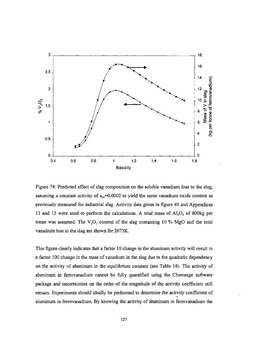
Citation preview

VANADIUM RECOVERY IN THE ELECTROshyALUMINOTHERMIC PRODUCTION OF
FERROVANADIUM
deur
Matthys Karel Gerhardus Vermaak
V oorgele ter vervulling van In deel van die vereistes vir die graad
Magister in Ingenieurswese
in die Departement van Materiaalkunde en Metallurgiese
Ingenieurswese Universiteit van Pretoria Pretoria Republiek van
Suid-Afrika
Projekleier Professor PC Pistorius
Januarie 2000
Aan Ilse met liefde
2
ACKNOWLEDGEMENTS
I would like to thank and herewith express my sincere appreciation to the following
people and institutes
bull Prof Chris Pistorius my supervisor for guidance and continuous support
bull S Havenga for all her support
bull Eben Bernardo and A Brugman for appreciating the need for this research and the
opportunity
bull Highveld Steel and Vanadium Corporation Limited for financial support
bull Department of Material Science and Metallurgical Engineering Pretoria University
for facilities
bull S Verryn and M Loubscher of the Geology Department for help in various analyses
bull A Botha of the Electron-microscopy section for assistance and thrust bestowed upon
me to use the electron-microscope after-hours
bull R Muir for manufacture and repair of countless special glassware equipment
bull My father mother Leslie Pieter Batsie lIse and her parents Muller and other friends
for their prayers continuous support and patience throughout
bull My fellow graduate students Rian Giel Jose Michelle Niel Riaan Ferdus Colette
Nana Daudet and Alain for their support and advice
bull The Lord for the abilities He gave me and the opportunities to develop them
SOLI DEO GLORIA
ii
V ANADIUM RECOVERY IN THE ELECTRO-ALUMINOTHERMIC PRODUCTION OF FERROV ANADIUM
by
Matthys Karel Gerhardus Vermaak
Prof PC Pistorius
Department ofMaterial Science and Metallurgical Engineering
Master Degree in Engineering
Abstract
Ferrovanadium IS sometimes produced from V20 3 in electric arc furnaces using
aluminium as reductant CaO fluxes the alumina which forms during reduction of the
vanadium oxide Vanadium recovery in the electro-aluminothermic process is mainly
controlled by losses to the slag These include metal droplet entrainment ( these droplets
remain in the slag after solidification) and unreduced vanadium oxides in the slag Both
these factors might be a significant cause ofvanadium losses
To quantify factors which can affect the equilibrium vanadium loss the vanadium oxide
activity coefficient was measured experimentally for different slag compositions
Hydrogen-water mixtures were used to control the partial oxygen pressure (ca 10-13 atm)
over CaO-A1203 slags contained in vanadium crucibles at 1700degC gas phase mass transfer
was controlled by jetting the gas mixture onto the slag surface Manipulation of the redox
conditions at a single slag composition and temperature showed that - as expected - the
vanadium is present in the trivalent state in the slag The slag basicity (CaOIAl20 3 ratio)
was found to have a very strong effect on the activity coefficient of V015 with clear
implications for the effect of plant practice on vanadium loss The laboratory equilibrium
results were compared to EDX analyses obtained from actual industrial slag samples
Analysis of the industrial slags indicate that slags with higher Al20 3 contents clearly have
lower vanadium oxide contents
An alteration of the slag composition by adding less CaO will lower the soluble vanadium
loss inevitably changing the separation of the solid ferrovanadium phase from the slag
phase The effect of slag basicity on metal droplet entrainment was assessed by
iii
investigating solidified slag samples The effect of droplet entrainment on vanadium loss
could not be fully quantified due to the strong segregation behavior and crowding close to
the slag-metal surface Samples which were taken close to this interface showed unusually
high vanadium losses compared to samples taken at the top of the bulk slag sample
Equilibrium calculations were also perfonned to predict the relative influence of
temperature MgO content of the slag and aluminium content of the ferrovanadium on
oxidic vanadium loss The activity-composition relations for the species in the slag and
ferrovanadium were estimated using the Chemsage software package The lower predicted
vanadium content of the slag compared to industry is probably the result of uncertainties
regarding the aluminium activity Nevertheless lower MgO contents of the slag higher
aluminium contents of the ferrovanadium and lower tap temperatures will yield lower
vanadium oxide losses to the slag
Keywords Key Words electro-aluminothennic process ferrovanadium vanadium
activity coefficient slag-metal equilibrium basicity slag losses metal droplet
entrainment
iv
VANADIUMHERWINNING IN DIE ELEKTRO-ALUMINOTERMIESE PRODUKSIE VAN FERROVANADIUM
deur
Matthys Karel Gerhardus Vennaak
Prof PC Pistorius
Departement Materiaalkunde en Metallurgiese Ingenieurswese
Meestersgraad in Ingenieurswese
Opsomming
Ferrovanadium word soms van V20 3in In elektriese boogoond vervaardig met aluminium
as reduktant CaO dien as vloeimiddel vir die alumina waf gevonn word tydens die
reduksie van die vanadiumoksied Vanadiumherwinning in die elektro-aluminotenniese
proses word hoofsaaklik deur metaaldruppelvasvanging (die druppels bly vasgevang in
die slak nadat stolling plaasgevind het) en ongereduseerde vanadiumoksied in die slak
beheer Beide die meganismes is moontlik verantwoordelik vir beduidende
vanadiumverliese
Faktore wat die ewewigvanadiumverliese kan beYnvloed kan gekwantifiseer word deur
die vanadiumoksiedaktiwiteitskoeffisient eksperimenteel VIr verskillende
slaksamestellings te bepaal Water-waterstofgasmengsels is gebruik om die parsiele
suurstofdruk (ca 10-13 atm) by 1700degC oor CaO-A~03 slakke wat in suiwer
vanadiumkroese geplaas is te beheer Gasmassa-oordrag is beheer deur die gasmengsel
direk op die slakoppervlakte te spuit Verandering van die redokstoestande vir In enkele
slaksamestelling en temperatuur toon soos verwag dat V 3+ die stabiele oksidasietoestand
is Dit is bevind dat die slakbasisiteit (CaO AI20 3-verhouding) In baie sterk invloed op die
vanadiumoksiedaktiwiteitskoeffisient (VOu ) het met duidelike implikasies vir die
aanlegpraktyk ten opsigte van vanadiumverliese Die laboratoriumewewigsresultate is toe
met EDS analises van industriele slakke vergelyk Die analises toon aan dat slakke met In
laer alumina-inhoud laer vanadiumoksiedvlakke het
In Wysiging van die slaksamestelling deur minder CaO by te voeg sal
vanadiumoksiedverliese verlaag maar die skeidingsgedrag van die vaste
ferrovanadiumfase sal noodwendig ook verander Die effek van slakbasisiteit op
v
metaaldruppelvasvanging is aangespreek deur industriele slakke te ondersoek Die effek
van slakbasisiteit kon nie ten volle gekwantifiseer word nie weens die sterk
segregasiegedrag en die versameling van die metaaldruppels naby die slakshy
metaalintervlak Monsters wat in die omgewing van die intervlak geneem is het
ongewoon hoe vanadiumverliese getoon vergeleke met monsters wat aan die bokant van
die blokslakmonster geneern is
Die relatiewe invloed van die MgO-inhoud van die slak die aluminiuminhoud van
ferrovanadium en die tapternperatuur is voorspel deur ewewigsberekeninge uit te voer
Die beraamde samestelling-aktiwiteitsverwantskappe van die spesies in ferrovanadium en
in die slak is verkry deur van die Chern sage sagtewarepakket gebruik te maak Die laer
voorspelde vanadiumoksiedinhoud van die slak vergeleke met aanlegdata is toe te skryf
aan onsekerhede wat betref die aluminiumaktiwiteit Ten spyte hiervan sal laer MgOshy
vlakke in die slak hoer aluminiumvlakke en laer taptemperature die vanadiumopbrengs
verhoog
Sleutelwoorde elektro-aluminotermiese proses ferrovanadium vanadium
aktiwiteitskoeffisient slak -metaalewewig basisiteit slakverliese
metaaldruppelvasvanging
vi
Table of contents
1Literature study 1
11 Introduction 1
12 Production of ferrovanadium 1
121 Introduction 1
122 Carbon reduction 2
123 Silicon reduction 4
124 Aluminium reduction 4
1241 Reduction of vanadium oxides 4
1242 Aluminothennic reduction 5
1243 Electro-aluminothennic production of ferrovanadium 9
1244 Factors influencing vanadium recovery in the electroshyaluminothennic production of ferrovanadium 15
12441 The loss ofvanadium reverts due to theft 15
12442 Loss ofvanadium units as oxide spillages during handling and transportation 15
12443 Loss of vanadium units as reverts 16
12444 Metal droplet entrainment 16
124441 Influence of the physicochemical properties of the slag on the separation of the solid phase 19
12445 Vanadium loss due to unreduced oxides in the high-alumina slag 26
13 Thermodynamic properties 27
131 Behavior of systems similar to the vanadium systems 27
132 Estimation of the partial oxygen pressures in the industrial ferrovanadium production process 29
vii
14 Research problem and objectives 35
15 Investigation into experimental techniques and procedures 36
151 Evaluation ofdifferent gas mixing systems 36
152Experimental evaporation technique and procedure 38
153 Kinetics of the vanadium oxidation reaction 44
16 Conclusion 50
2 Experimental techniques 51
21 Introduction 51
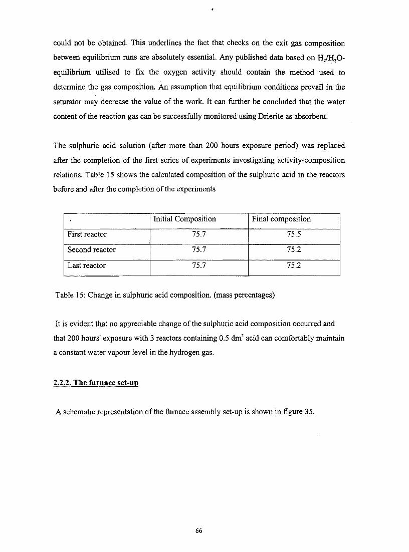
22 Experimental set-up 51
221 Gas system set-up 51
222 The furnace set-up 66
223 Quenching set-up 71
224 Crucibles 73
23 Experimental procedure 74
231 Slag preparation 74
232 Experimental run 76
233 Sample analysis 76
3 Equilibrium time determination 81
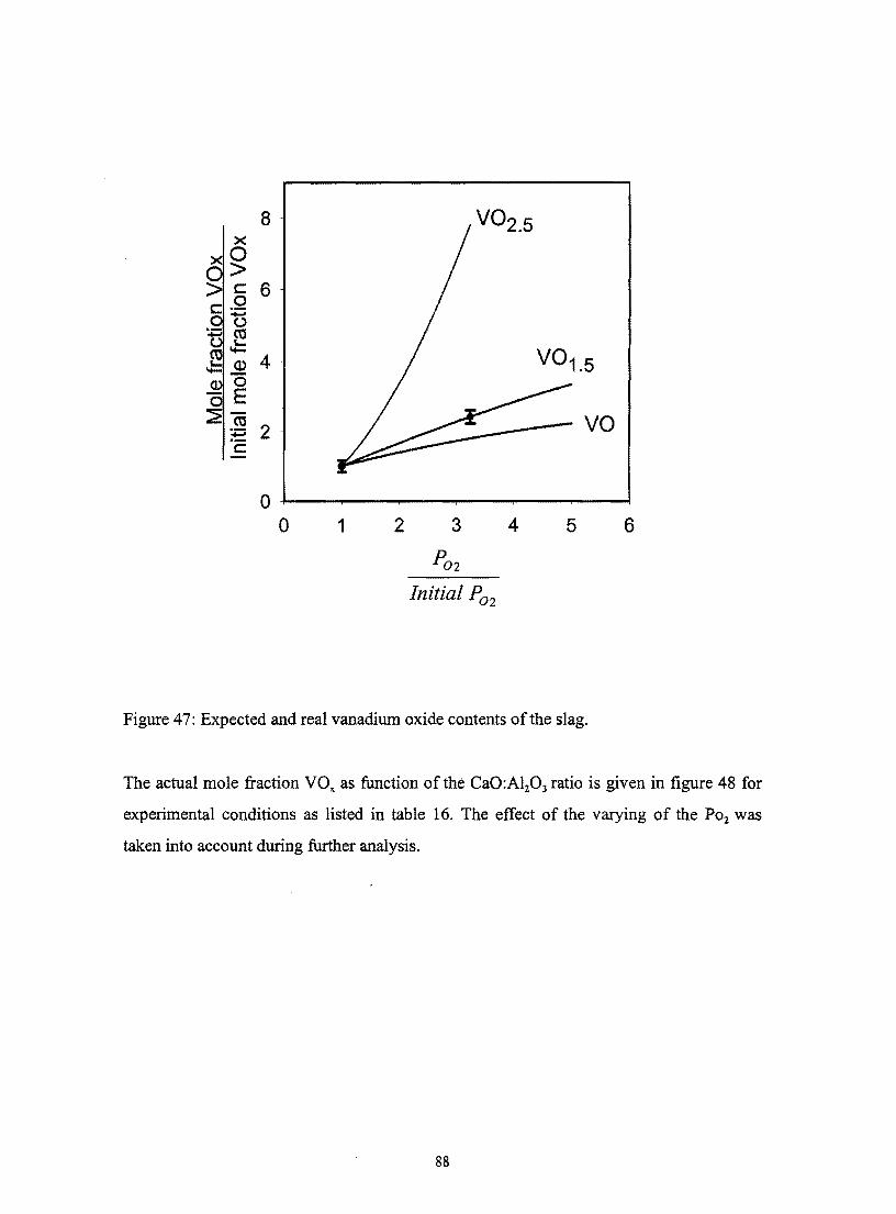
4 Results and discussion 84
41 Activity coefficient relations 84
5 Industrial slag sample investigations 92
51 Introduction 92
52 Oxidic phase analysis 92
521 Experimental procedure 92
5211 Sample preparation 92
viii
522 Results and discussion
5221 Oxidic phase investigations
5222 Composition relations of the oxidic phase
5223 Industrial slag sampling
5224 Industrial XRF relations
53 Metallic phase analysis
531 Introduction
532 Experimental procedure
5321 Sample preparation
5322 Procedure to determine droplet-size distributions and to estimate
the mass of vanadium associated with the metallic phase
533 Results and discussion
6 Equilibrium simulation calculations
61 Introduction
62 Results and discussion
7 Conclusion
8 Recommendations for feature work
9 References
Appendices
Appendix 1
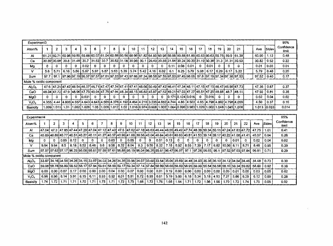
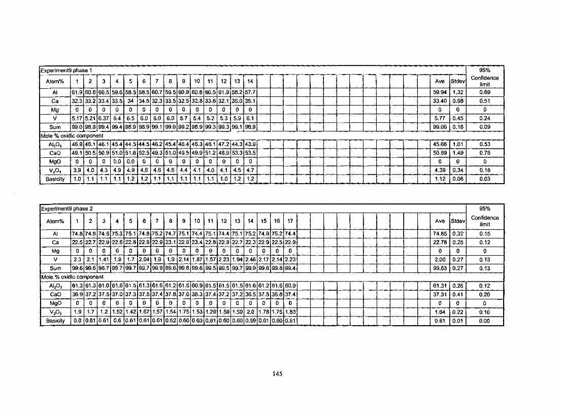
Appendix 2 EDX analysis of experimental slags
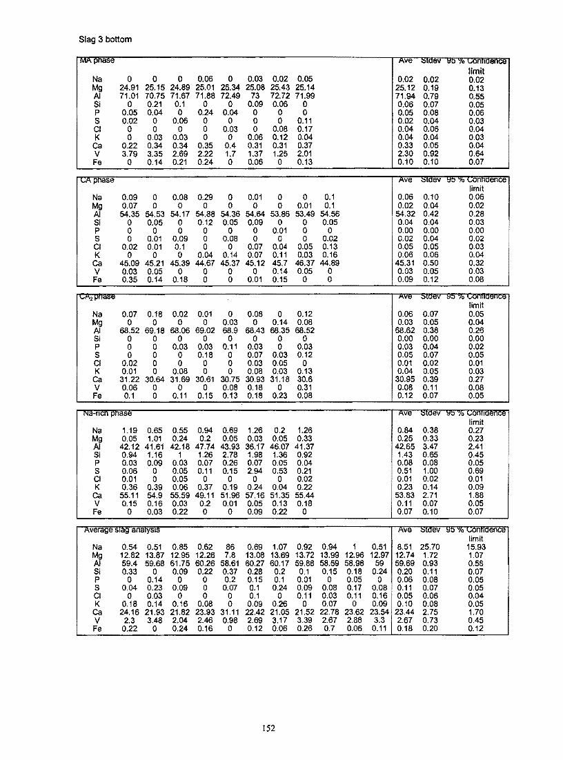
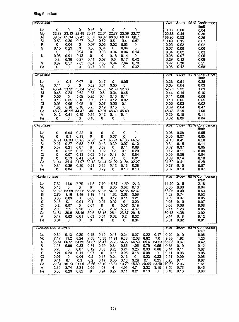
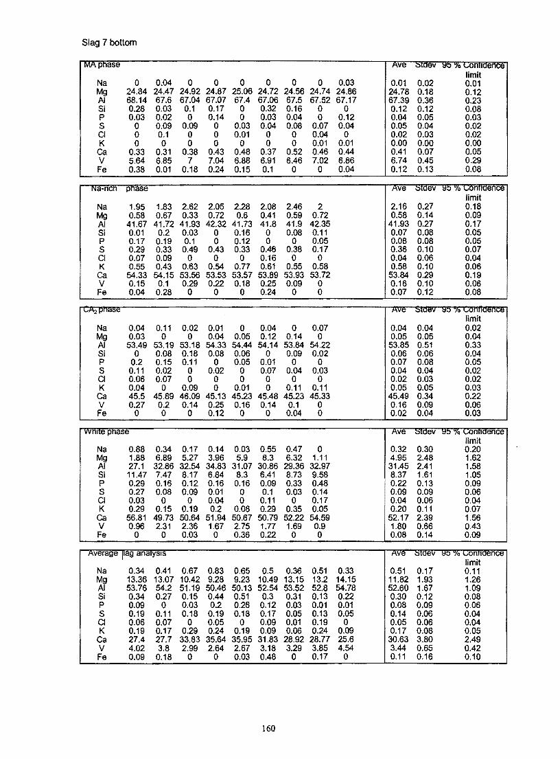
Appendix 3 Industrial slag analysis
Appendix 4 Summary of slag analysis
Appendix 5 Metal droplet analysis ofdipped sample
Appendix 6 Chemical composition ofdipped sample
ix
94
94
100
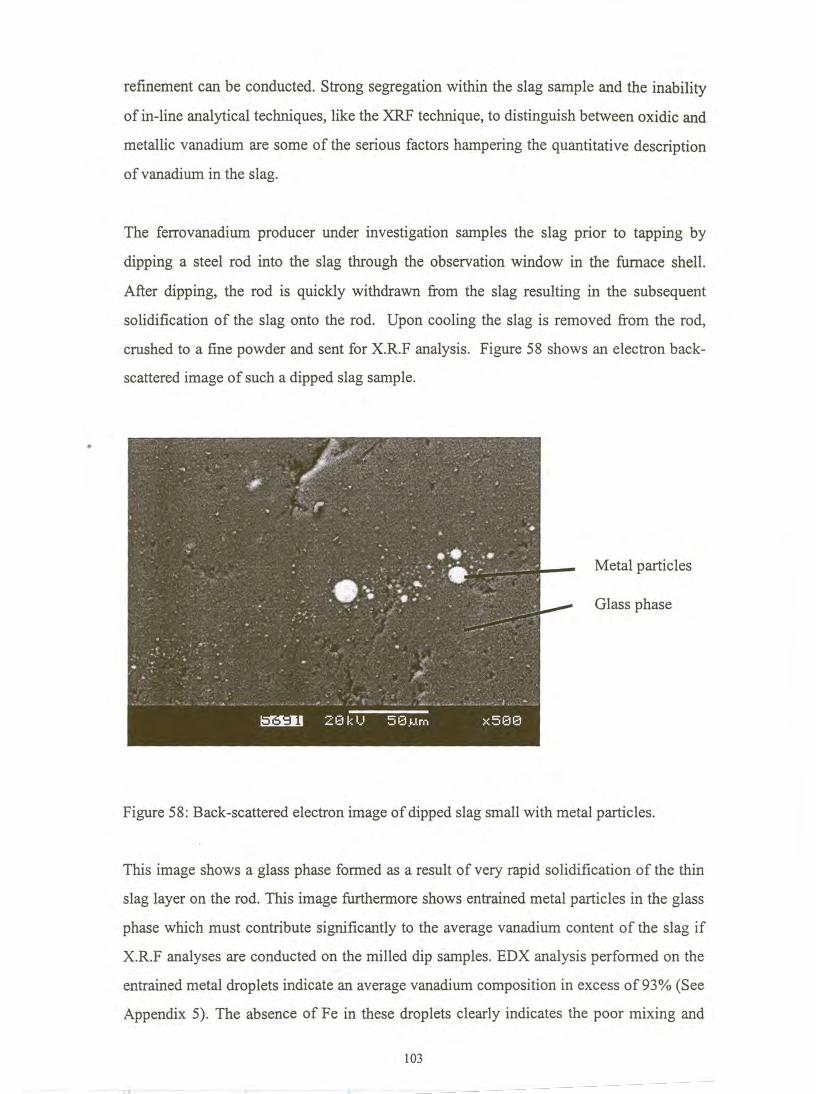
102
105
108
108
108
108
108
110
120
120
120
132
134
135
139
139
140
147
162
163
165
Appendix 7 Metal droplet analysis 166
Appendix 8 Estimated activity data ofspecies in the CaO-A1203 system 170
Appendix 9 Estimated activity data ofMgO in the CaO-A120 3-MgO system 171
Appendix 10 Estimated activity data ofA120 3in the CaO-A1203-MgO system 172
Appendix 11 Estimated activity data of A120 3in the CaO-A120 3-MgO system 175
Appendix 12 Estimated activity data ofAl and V in the FeV system 177
Appendix 13 Estimated activity data of Al and V in the FeV system 179
x
1 Literature study
11 Introduction
Vanadium recovery in the electro-alumino thermic process is influenced by a number of
factors relating to the production process for instance raw materials handling flux
additions temperature control and tapping procedure Because of the high selling price of
the final product is it essential to identify and investigate the relative effect of each factor
on the vanadium recovery aiming to optimize the process The most important recoveryshy
linked factors that still await clarification can if possible be addressed by performing
experiments The objective of the following discussion is to provide background on some
areas that were studied experimentally by the author
12 Production offerrovanadium
121 Introduction
Ferrovanadium represents today a group of vanadium compounds and alloys some of
which do not even contain iron but all of which serve the function of introducing
vanadium into iron and steel It is difficult to produce pure vanadium metal because
vanadium readily reacts and absorbs oxygen nitrogen and carbon Furthermore the
presence of impurities renders the vanadium metal brittle (Gupta1992)
Ferrovanadium is produced by the reduction of vanadium bearing starter materials
including slags boiler residues fly ash and vanadium oxides using carbon silicon or
aluminium as reductant The vanadium oxides can be in the form ofV20 s V20 4 V20 3 or
mixtures of these oxides The exothermicity of the reaction is a function of the level of
vanadium oxidation and the concentration of each species in the raw materiaL This would
therefore determine to what extent external energy is required Depending on the
production process and raw materials used the concentration of vanadium in
ferrovanadium generally ranges from 40 to 85 by weight and the industry classifies
ferrovanadium into grades accordingly Table 1 shows typical chemical specifications for
commercial forms of ferro vanadium
Alloy Composition (Mass )
V C N Al Si P S
SO -60 ferrovanadium SO-60 02 max 2 max 1 max OOS max OOS max
70 -80 ferrovanadium 70-80 1 max 2Smax OOS max 010 max
80 ferrovanadium 77-83 OSmax OS max 12S max OOS max OOS max
Carvan 82-86 10S-145 01 max 01 max OOS max 010 max
F errovanadium carbide 70-73 10-12 05 max OOS max OOS max
Ferrovan 42 min 08S max 7 max
Nitrovan 78-82 10-12 6 min 010 max 01 max 005 max 005 max
Mn
OOS max
OOS max
4S max
005 max
Table 1 Typical chemical compositions with Fe as balance for commercial forms of
ferrovanadium (Gupta1992)
The methods of producing ferrovanadium are discussed below
122 Carbothermic reduction
Reduction with carbon is conducted in a submerged-arc furnace Carbon in the form of
coke coal char or charcoal can be used Carbothermic reduction is endothermic and so
the process is energy intensive Thus successful production of ferrovanadium by carbon
reduction of vanadium pentoxide requires the introduction of the furnace charge into the
high temperature zone under strongly reducing conditions The furnace usually has a
rectangular cross section using either two or three electrodes arranged in line The
electrodes create a high temperature reduction zone (Gupta1992) The charge mainly
consists of vanadium oxide carbon source steel scrap and fluxing agents
The charge is fed into the high-energy reduction zone and ferrovanadium and slag
accumulate below the arc and are tapped at 4-12h intervals (Hayward 1952)
A typical ferrovanadium composition for this process is as follows 33-42 V 3-5 Si
3-35C and balance Fe (Gupta1992) The high residual carbon content in the alloy and
the difficulty in regulating the carbon content have made carbothermic reduction in the
arc furnace less attractive than alternative routes The carbon reduction process is mainly
used for the production of high C-grade ferrovanadium for example Carvan (85
2
Vanadium 12 Carbon 2 iron) used in applications where carbon and carbides are
not detrimental
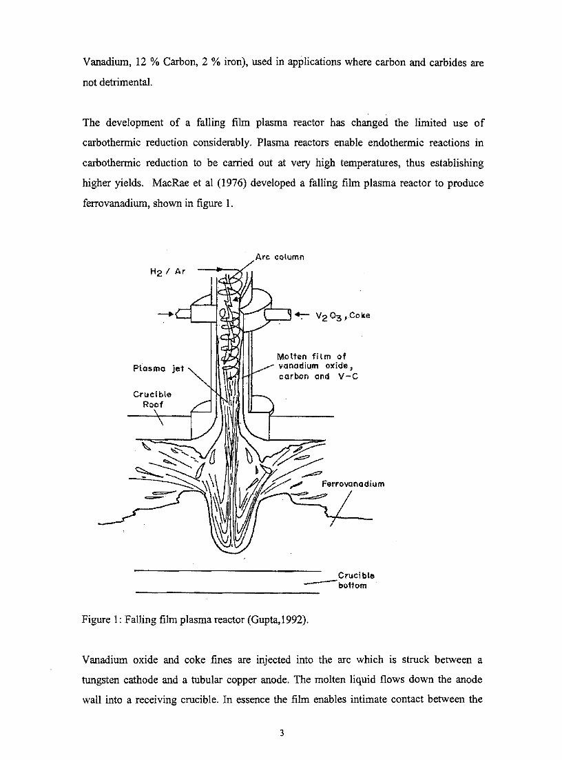
The development of a falling film plasma reactor has changed the limited use of
carbothermic reduction considerably Plasma reactors enable endothermic reactions in
carbothermic reduction to be carried out at very high temperatures thus establishing
higher yields MacRae et al (1976) developed a falling film plasma reactor to produce
ferro vanadium shown in figure 1
Arc cotumn
H21 Ar
Plasma jet Molten film of v(madium oxide carbon and V-C
Ferrovanadium
Crucible --bo1tom
Figure 1 Falling film plasma reactor (Gupta 1992)
Vanadium oxide and coke fines are injected into the arc which is struck between a
tungsten cathode and a tubular copper anode The molten liquid flows down the anode
wall into a receiving crucible In essence the film enables intimate contact between the
3
reactants and the long residence time provides sufficient time for heat transfer thus
driving the reaction almost to completion The product contains typically 42 V 53 Fe
and 3 C Despite the good heat transfer to the reactants the power consumption is still
3200 kWhton ferrovanadium produced
123 Silicon reduction
In this route the reductant is a high-grade ferrosilicon containing 75 silicon Silicon is
not a powerful reducer of vanadium oxides thus a two-stage process is required
Technical grade vanadium pentoxide is smelted to produce ferrovanadium containing
about 30 vanadium with a considerable amount of residual silicon According to
Khodorovsky et al (1967) the slag composition is 50-55 CaO 5-10 MgO 28-30
Si02 and 05 V The overall reaction can be represented by
(1)
The primary metal is refmed with vanadium pentoxide and lime in a second step and the
secondary slag is returned as part of the charge to produce primary metal Lower
vanadium oxides such as V 203 and VO interact with silica to form vanadium silicates
thus making the reduction process difficult and more complicated As a result the slag
traps some vanadium and the recovery rarely exceeds 75-80 (Gupta1992)
124 Aluminium reduction
The reduction of vanadium oxide with aluminium can be further subdivided into the
aluminothermic (thermit) and the electro-aluminothermic processes The nature of the
vanadium oxide used as input material governs the production route as is indicated in the
next sections
1241 Reduction of vanadium oxides
The reduction of vanadium oxides by aluminium can be represented by the following set
of reactions (The heats of the reactions were calculated using correlations of
4
Kubaschewski et al (1993) for enthalpy values at 298 K and 2073 K for the reactants and
products respectively)
(2)
(3)
(4)
3VO + 2AI ~ 3V + Al20 3 Mfo - 152 104 Jmol V (5)
The enthalpy of the exothermic reaction can be used to predict whether the reaction
releases enough energy to melt the metal and slag The ratio of the heat of the reaction
and the molecular weight of the products is generally used to determine the exothermicity
of the reaction If the ratio gt4 500 Jgram then the reaction is violent under 2250 Jgram
external supply of heat is necessary and between 2250 Jgram and 4500 Jgram the
reaction develops in a controlled manner and external energy is not necessary
(Yucel1996) Only slag reaction 2 is sufficiently exothermic to obtain liquid metal given
the very high melting temperature of ferrovanadium (typically 1750 degC)
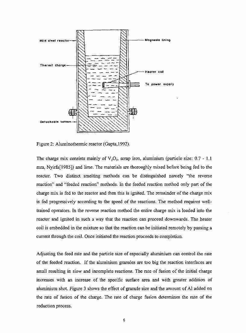
1242 Aluminothermic reduction
The process can be characterized by reaction 2 This reaction is strongly exothermic and
once it has been initiated it can both melt the iron added to make the alloy and allow for
effective separation of the alloy and the high aluminium slag The aluminothermic reactor
is presented in figure 2
5
Mild 5teel reactor J~~--- Magnesia lining
Thermit charil--I-k~-=--~
Heatr coil
To power supply
Detachable bottom
Figure 2 Aluminothermic reactor (Gupta 1992)
The charge mix consists mainly of V20 S scrap iron aluminium (particle size 07 - 11
mm Nyirfa[1985]) and lime The materials are thoroughly mixed before being fed to the
reactor Two distinct smelting methods can be distinguished namely the reverse
reaction and feeded reaction methods In the feeded reaction method only part of the
charge mix is fed to the reactor and then this is ignited The remainder of the charge mix
is fed progressively according to the speed of the reactions The method requires wellshy
trained operators In the reverse reaction method the entire charge mix is loaded into the
reactor and ignited in such a way that the reaction can proceed downwards The heater
coil is embedded in the mixture so that the reaction can be initiated remotely by passing a
current through the coil Once initiated the reaction proceeds to completion
Adjusting the feed rate and the particle size of especially aluminium can control the rate
of the feeded reaction If the aluminium granules are too big the reaction interfaces are
small resulting in slow and incomplete reactions The rate of fusion of the initial charge
increases with an increase of the specific surface area and with greater addition of
aluminium shot Figure 3 shows the effect of granule size and the amount of Al added on
the rate of fusion of the charge The rate of charge fusion determines the rate of the
reduction process
6
Rate of fusion gcm2min of initial charge
Specific surface area cm2g of the aluminium particles
Figure 3 Effect of the amount of aluminium and of its specific surface area on the fusion
rate of the charge (Nyirfa 1985) Curve 2 represents the stoichiometric amount of
aluminium added The other curves are where this amount is reduced by 20 (Curve 1)
and increased by 20 (Curve3)
Large size granules cause increased amounts of large-size drops of alloy being trapped in
the slag Although the increase of aluminium above the stoichiometrically needed amount
results in faster reactions and improves the vanadium recovery it does increase the final
Al content of the alloy There are strict specifications set by the consumer regarding the
aluminium content of the alloy indicated by Table 1 thus necessitating the optimization
of the recovery process by adjusting parameters influencing the vanadium distribution
between slag and metal One such parameter is the slag basicity The slag basicity has a
dual influence on the vanadium recovery in the sense that it influences the vanadium
activity coefficient and the slag viscosity which in tum has an effect on the separation of
metal droplets from the liquid slag In addition to this the slag volume also increases with
an increase in basicity Figure 4 shows the effect of the slag basicity on the V 205 content
7
of the slag No indication is given whether the metal particles in the slag were avoided
during analysis
~L~____________________________------4 -sfl C9 ~~middot----------------------~
t~~--------------~~I
J bull
z~--~------~~---------
430 1135 8
Figure 4 Effect of the slag basicity (mass CaO mass AI20 3) on the V 20S content of
the slag (Nyirfa1985)
From this figure it is evident that an optimum exists at a ratio mass CaO mass Al20 3
of around 025 -03 which must be achieved if the recovery is to be maximized if the
effect of viscosity on the recovery can be neglected In other words the effect of slag
basicity on droplet entrainment and its subsequent contribution to the total vanadium loss
to the slag are not taken into account Nothing is mentioned about the type of refractory
lining this industrial smelting process (Nyirfa1985) As indicated later in this work a
substantial amount of magnesite refractory lining dissolves in the presence of a
high-alumina slag If it is assumed that effect of MgO is similar to CaO then the effect of
the former on the vanadium distribution cannot be neglected and should be incorporated
in the basicity relationship No indication is given in this work regarding the effect of slag
basicity on the phenomenon ofdroplet entrainment
In the next paragraph the second of the AI-based reduction processes will be discussed
(ie electro-aluminothermic reduction)
8
1243 Electro-aluminothermic production of ferrovanadium
As indicated by the title of this work factors influencing vanadium recovery in the
electro-aluminothermic process will be under detailed investigation For a lower
vanadium oxidation level in the feed material less Al is required and consequently the
reaction is less exothermic The use of V20 3 and V20 4 as raw materials necessitates the
addition of external energy to sustain the reduction process This process is much less
violent and thus more controllable than the aluminothermic process This allows the
operator better control over the process because temperature is an important factor
concerning the quality of the product vanadium yield viscosity of the slag the
separability of the slag and the metal and the dissolution of the refractory lining The
equilibrium constant of this reduction reaction is strongly temperature dependent thus coshy
determining the distribution of vanadium between the metal and the slag Electric power
consumption in ferro-alloy production is compared in Table 2 Although the production of
ferrovanadium by an electric arc furnace process does not require as much power as other
ferro-alloy processes it can still amount to a substantial percentage of the total cost and
should therefore be carefully controlled
9
Alloy Specification Energy consumption (kWhton) of alloy
Ferrochrome 006 C 18000
i
IC 10000
I 4-6C 7000
Ferrosilicon I
45 Si 6000
i 75 Si 9000
Ferromanganese 05C 7000
1-2C 3000
Silico-manganese 65Mn 9000
Ferrotitanium 26Ti 7500
Ferrovanadium 80V 1100
Table 2 Electric power consumption in ferro-alloy production All the electric power
consumption estimates were taken from Sieveking(1945) except that of ferrovanadium
which is typical of a South African producer with V20 3 as feed
Ferrovanadium can be produced from the trivalent oxide (V20 3) by reduction with
aluminium in an electric arc furnace adding iron in the form of scrap and lime (CaO) to
flux the alumina (AI20 3) - the byproduct from the reduction reaction
Typical compositions of the metallic product and the slag are given in Table 3 based on
figures for a South African producer A corresponding mass balance is depicted
schematically in Figure 5 the mass balance shows a mismatch of some 140 kg per tonne
of ferrovanadium This is largely the result of the substantial wear of the magnesia
refractory lining of the furnace for which data could be obtained the entire MgO content
of the slag (see Table 3) is the result of refractory wear in this furnace
10
Table 3 Typical metal and slag compositions (mass persentages)
Metal V 80 I~
11 21 365
V20 a 1210 kg CaO (260 kg)
AI (440 kg) Fe (170 kg)
~ Slag (1230 kg)
Ferrovanadium (1000 kg)
Figure 5 Schematic depiction of a ferrovanadium furnace which uses VZ0 3 as feed with an approximate mass balance
Excessive tap temperature can reduce the life of the magnesite refractory lining quite
substantially Recorded tap temperatures as high as 1900 degC are reported from industry
The high temperature necessitates a magnesite refractory lining although the
incompatibility between the Alz0 3-rich slag and the lining results in excessive wear
Point E on the line D-G in figure 6 depicts the average industrial slag composition of the
South African ferrovanadium producer If a slag with average composition E is brought
is contact with the refractory lining mainly MgO the average composition of the reacting
slag will change along line D-G At a temperature of 1800degC the slag would only be
saturated with spinel (MgOAI20 3) when the average composition reached point F
indicating that the industrial slag is not saturated with MgO
11
--shy-- - - 100
jb - 0 20
40 60 80
A AI20 3 C CaO M MgO
1
CaO MgO G Mass MgO shy
Figure 6 AI203-CaO-MgO ternary phase diagram (Verein Deutscher
Eisenhiittenleute1995)
Industry observations indicate that deep furrows especially around the tap hole are
observed after the completion of each heat These deep furrows are from time to time
patched up with fettling material containing around 90 MgO The consumption of the
fettling material is on average about 70 - 100 kg per heat and this value gradually
increases as more excessive wear occurs at the later stages of the lining life This fettling
practice allows the ferrovanadium producers to attain between 200 and 300 heats on a
lining
Mass balances performed and depicted in figure 5 on the smelting process showed that the
high MgO content of the slag has its source from the refractory lining and the fettling
12
material being used to extend the life ofthe refractory lining The MgO content of the slag
can thus serve as marker of lining wear and should therefore be carefully monitored
In addition to refractory wear due to the dissolution of the magnesite refractory lining in
the Alz0 3-rich slag the evaporation of Mg (produced by the reduction of MgO) is
possible under the prevailing conditions The typical tap temperature is around 1800degC
and an estimation of the reigning partial oxygen pressure ( see section 151 on activityshy
composition relations) reveals values POz ~lOIS atmospheres Magnesia vaporizes at low
oxygen pressures and high temperatures according to the following reaction
MgO =Mg(g) + O2 (6)
The calculated equilibrium partial magnesium vapour pressure (PMg) is 0135 atm for a
P02 = 188 10-14 atm (see Table 10) at 2073K (This was calculated using correlations of
Kubaschewski et aL [1993] for free energy values) All the fume and dust liberated during
the smelting process are withdrawn from the furnace using an external suction fan The
dust is subsequently separated from the smelter exhaust gas using bag filters The
magnesium fumes emitted from the furnace re-oxidize at the colder regions higher up in
the furnace during its ascent The high MgO content of the recycled dust shown in Table
4 is indicative of magnesium vaporisation
Component
V20 S 548
CaO 27
I Al20 3 326
MgO 82
Fe20 3 09
Si02 05
Table 4 Chemical composition of recycled bag filter dust of a South African
ferrovanadium producer
13
The flow sheet of a South African ferro vanadium producer is shown in figure 7
sectIiop~
s~ ~ Furnace feed hopper
=~kodlaquo
CaF
r Cleanair
Stack
Refractory material
~ SlagI--l _ I--l bull ~ 0Slag crusher
Slag dumpt pot Slag bin
_~pot
o --+ ~ - [IJhot + LJ blast =
Buttons I ScaleQuench tanks -____J
~riZ2IY~rr-----------------I Metterpingon
Primary ctUSher
+
T -
c 0 o
Secondary +I In
lttUSher 0
- - - Drums Ej EjEj
Scale~
Figure 7 FeV process flow sheet ofa South African producer
Fluorite is added just prior to tapping to lower the solidification temperature of the slag
The lower solidification temperature increases time available for separation of the
droplets thus increasing vanadium recovery During the reduction process vanadium
oxide is reduced to vanadium metal which subsequently reacts with molten iron and
aluminium to form the metal particles Not all metal particles especially not the smaller
ones settle out of the slag while in the liquid state This results in the entrainment of
metal droplets CaF2 further enhances refractory wear leading to more vanadium oxide in
the slag because MgO increases the alumina activity coefficient (See section 62) The
time between the addition of the CaF2 and tapping is kept as short as possible to limit the
effect of the CaF2 on the refractory lining V20 S flakes (around 230 kg for a heat size of
1100 kg Fe V) are added with the raw materials to enrich the metal with vanadium
17~~r tJ tJ tJ eo Vibratory screenIn Bm In
14
1244 Factors influencing vanadium recovery in the electro-aluminothermic
production of ferrovanadium
The aim of this next section is to identify and evaluate all possible factors influencing
vanadium recovery in the electro-aluminothermic production of ferrovanadium The
limited availability of applicable information in some instances hinders the evaluation of
the process
12441 The loss of vanadium units due to theft
As in case of many valuable commodities such as copper and nickel a lucrative trade
exists also in ferrovanadium on the black market The price of ferrovanadium is linked
mainly to the steel price and ranges from $7kg up to $32kg Sporadic instances of theft
are reported from time to time but one gets the impression that this is only the tip of the
iceberg Especially the disappearance of small quantities of ferrovanadium on a daily
basis will go undetected through the system This integrated over a certain period will
lead to substantial losses A number of precautionary measures such as high fencing
security and a good and strict practice can be taken to minimize the effect of theft
although the total elimination of such trade is very unlikely Due to the lack of
information available no further discussion of theft as a possible cause of vanadium loss
will be given here
12442 Loss of vanadium units as oxide spillages during handling and
transportation
The fine vanadium oxide powder (consisting mainly ofV20 3 and small quantities ofV02)
is transported by truck in metal containers (known as kibbles) from the oxide producing
plant to the ferrovanadium plant The kibbles are lifted with a fork lift onto the discharge
unit located near the raw material silos The kibble discharge hatch is subsequently
opened releasing the contents into a bucket elevator unit from where the oxide is
transported into the silos An appreciable amount of oxide dust is generated during the
discharge stage The dust escapes from the bucket elevator unit through openings and is
15
released into the plant In addition to the health risk posed by the dust a substantial
amount of vanadium is lost during the handling activities such as charging of the furnace
Ways have to be found to eliminate vanadium loss due to dust formation these may
include pelletizing sintering briquetting or the installation of a pneumatic conveying
unit
12443 Loss of vanadium units as reverts
Recyclable ferrovanadium spillages which occur during the tapping process are
commonly known as reverts Some ferrovanadium smelting processes utilize a number of
small tapping pots instead of one large pot This sometimes leads to the phenomenon
where metal is tapped onto solidified slag The first few pots taking mainly the slag
constituent from the furnace are not completely filled When on subsequent tapping the
remainder of the furnace contents now mostly ferrovanadium metal is tapped into the
remainder of the tapping pots the capacity is sometimes exceeded This forces the
operator to re-use to the first few tapping pots now containing solidified slag to
overcome the lack of capacity As a result some of the reverts are dumped together with
the slag
The reverts can b~ recovered by crushing and jigging of the old dump on an annual basis
Most of the misplaced ferrovanadium is now recycled as feed material to the furnace The
loss of ferrovanadium as reverts can be eliminated by utilizing a single slag pot with a
capacity which exceeds that of the furnace slag content In addition to the savings in
spillage losses a large slag pot also promotes the separation of the metal phase from the
slag phase during solidification as indicated in the next session on metal droplet
separation
12444 Metal droplet entrainment
Preliminary investigations conducted on industrial slag samples show two primary
mechanisms of droplet entrainment Figure 8 and 9 show images of entrained droplets
underlining the dual mechanisms leading to droplet entrainment
16
The results ofEDS analysis conducted on the entrained droplets depicted in figure 8 and
9 are showed in Table 5
V-droplets FeV-droplets
V 72-96 82
Fe 0-20 154
AI 0-11 12
Table 5 EDS-results on entrained droplets showed in figure 8 and 9
The vanadium content of the entrained droplets showed in figure 9 corresponds to the
ferrovanadium bulk composition given in Table 5 indicating entrainment as a result of an
incorrect tapping procedure In other words the entrainment can be a result of a too slow
tapping stage by which ferrovanadium is tapped onto cold liquid slag Not enough time
is allowed before complete solidification resulting in large entrained metal droplets with a
composition similar to that of the bulk metal A re-evaluation of the tapping practice
could eliminate the loss of vanadium as entrained ferrovanadium droplets
The high vanadium content and small droplet size indicate that the droplets showed in
figure 8 are most probably as formed during the reduction process before alloying with
iron Pure vanadium droplets are formed when the vanadium containing oxides are
initially reduced by molten aluminium The metallic droplets now agglomerate and
separate from the slag phase under their combined weight The pure vanadium droplets
subsequently form an alloy with the molten scrap iron in the bottom of the furnace The
generally low iron content of the vanadium droplets indicates the lack of intimate contact
between the droplets and the molten iron pool The vanadium recovery will increase with
the utilization of larger tapping pots due to the decrease in the cooling rate and the
subsequent increase in the metal separation periods thus yielding higher metal
recoveries The influence of slag properties on the separation of the solid phase will be
discussed in the section on the influence of physicochemical properties of the slag on the
separation of the solid phase
18
124441 Influence of physicochemical properties of the slag on the separation of
the solid phase
Any liquid-solid separation process can be divided into either free or hindered settling
conditions The crowding of particles is negligible in free settling conditions whilst
particle crowding becomes more apparent in hindered-settling conditions Effectively all
the resistance to motion in viscous slag systems is due to the shear forces or viscosity of
the fluid In addition to this preliminary results show the average entrained droplet
diameter to be 05 Jlm for V-particles and 5 mm for FeV-particles The separation of
metal particles or droplets from the slag therefore obeys Stokes law which assumes the
drag force of spherical particles to be entirely due to viscous resistance giving the
expression(Wills 1993)
D =31td11V (7)
With d = spherical particle diameter(m)
D = drag force (N)
11 = slag viscosity (Pas)
v = tenninal velocity (mls)
and
(8)
with Ps = particle density (kglm3)
Pr= slag density(kglm3)
Ps-Pr is know as the effective density of the particle and is fairly constant when slag and
ferrovanadium with constant composition are produced
Thus the viscosity of the slag has a large effect on the settling rate of solid particles The
viscosity of the slag is mainly influenced by temperature slag composition and the
presence of solid particles The relative viscous resistance on small spherical particles is
19
much larger than on large spherical particles with the same effective density If the
entrained particles are large enough to benefit from a lower slag viscosity a rise in the tap
temperature will reduce droplet entrainment The beneficial effect of temperature on
droplet entrainment may unfortunately be counterbalanced by the increase of soluble
vanadium in the slag The effect ofslag composition on the viscosity of the slag will now
be addressed
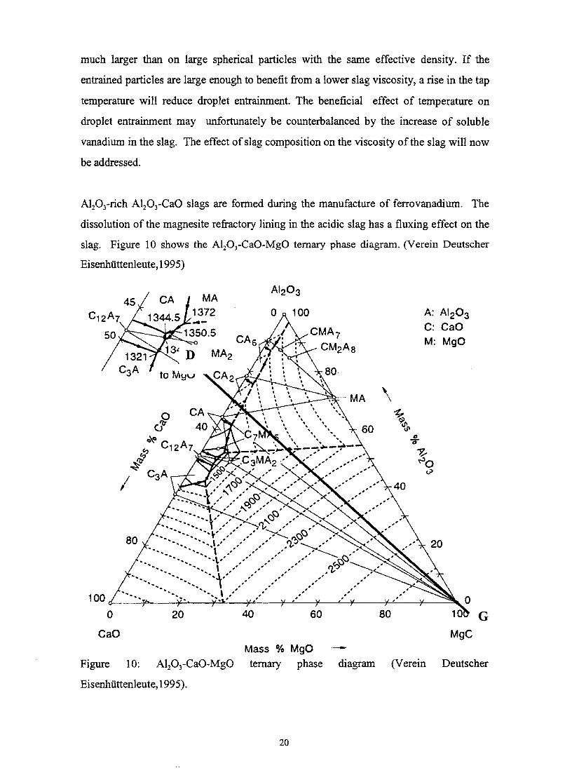
Al20 3-rich A120 3-CaO slags are fonned during the manufacture of ferrovanadium The
dissolution of the magnesite refractory lining in the acidic slag has a fluxing effect on the
slag Figure 10 shows the A1203-CaO-MgO ternary phase diagram (Verein Deutscher
Eisenhiittenleute 1995)
MA 1372 A AI20 3
C CaO M MgO
20 60 80 G CaO MgC
Mass MgO shyFigure 10 ternary phase diagram (Verein Deutscher
Eisenhiittenleute 1995)
20
If for example 70 A120 3- 30 CaO slag is brought into contact with MgO from the
lining the nominal composition will change alongside the line D-G A small quantity of
MgO (-4 ) will reduce the melting point of the slag from 1650 degC (the melting point of
a 70 AI20 3-CaO slag) to -1580 degC At the industry-reported maximum of around 10
MgO the liquidus temperature again reaches 1650degC Upon further dissolution of MgO
the melting point will increase and presumably so too the viscosity of the slag (at a given
temperature)
The longer the slag is in the liquid state and the lower its viscosity when molten the more
complete will be the separation of metal and slag The effect of CaO and MgO fluxing
additions on the viscosity ofhigh-alumina slags can be seen in figure 11 (Arkhipov1965)
Their study focused on factors effecting the more complete separation of the metal and
slag phases Physicochemical properties such as slag viscosity composition surface
tension interfacial tension and liquidus range of around 100 laboratory heats were
studied Three distinct slags were used to illustrate the influence of fluxing additions on
the metal droplet separability The composition of the three slags used is shown in Table
6
ISi02 Al20 3 CaO Ti02 MgO
I Slag 1 007 869 22 035 141
Slag 2 011 845 66 037 098
Slag 3 022 802 64 032 473
Table 6 Composition (mass percentages) of the three slags used to illustrate the effect of
fluxing additions on droplet entrainment(Arkhipov1965) Despite the chemical
compositions not adding up to 100 it can still be assumed that three slags with distinct
alumina contents were employed
Nothing is mentioned about the nature of the laboratory experiments conducted to give
rise to the results shown in figure 11 A nominal vanadium content of 85 in the
ferrovanadium was aimed for Figure 11 depicts the results as obtained from the three slag
samples
j I5 q ~7 b 0 ~ 21
b15J ilt ~ 1
10
Slag 1 8
Cl ro Ii) 6 5 iii Q) Slag 2 -E 4 ~ 0
2
o +-----~------r_----~----~------~----~ 005 010 015 020 025
mole CaO + mole MgO mole Al20 3
Figure 11 Metal droplet entrainment (expressed as percentage metal in the slag) as a
function of slag basicity (after Arkhipov 1965)
The AlzO) content of the slag of the South African ferrovanadium producer is
considerably lower see Table 3 than the tabulated values reported by the authors The
results depicted in figure 11 show that a slight alteration in the chemical composition of
the slag formed in the aluminothermic production of ferrovanadium has a considerable
effect on the separation of the liquid phases at low basicity
In order to attain a better understanding in the causes behind the more complete
separation of the liquid phases viscosity measurements can be carried out on synthetic
slags Viscosity investigations were carried out by Arkhipov et al (1965) on slags
produced in the production of ferrovanadium Table 6 show the composition of the highshy
alumina slags used in these investigations The viscosity measurements were carried out
in a vertical resistance tube furnace using a carbon reduction tube in which temperatures
around 2100degC were reported The temperature within the furnace was measured by
030 035
22
means of a tungsten-molybdenum thennocouple and the viscosity of the slag was
detennined by means of a vibration viscosimeter The influence of the fluxing additions
CaO and MgO on the viscosity on high-alumina slags is depicted in figure 12
lGOO 1700 1800 IJOD 2000 Temperalure bull C
Figure 12 Viscosity curves of high-alumina slags (e Slagl x Slag2 0 Slag3)
(Arkhipov1965)
It is evident from the curve that slag 3 provides the best conditions of droplet separation
in the temperature range of 1750 degC - 2000 0c Slags which give optimum vanadium
recovery must have a minimum viscosity prior to solidification as well as an optimum
composition to ensure minimum soluble vanadium loss The tenn soluble vanadium loss
refers to oxidic vanadium in the slag If for example the alteration of the slag
composition by adding fluxing agents is not beneficial to vanadium recovery with respect
to soluble vanadium loss then the separation of the liquid phases can be optimized by
tapping at a slightly higher temperature and utilizing a larger melt volume The smaller
the volume of the melt the more rapid the heat transfer to the surrounding environments
Figure 13 shows cooling curves of a range of slag compositions as well as that of an alloy
containing 85 vanadium and 82 iron The composition of each slag used is given in
23
Table 6 and the cooling curve of each slag is numbered accordingly Cooling curve four
refers to the cooling curve of the alloy
2000
~ 00 bull
~ ioJ
111111 Q) ~E 16IJO
~ 15011 0 S II IS
n
~~ ~l r ~ -
IIIL 1--
~ -
~ ~
-- -~
IiiI
r r~ 1
2 ~ ~ ~
~
r~ ij
-- 4 ~ -
~ ~~
Time min Figure 13 Cooling curves ofslags after tennination ofsmelting process (Arkhipov 1965)
1) Slag 1 2) Slag 2 3) Slag3 4)Alloy containing 85 vanadium and 82 iron
Figure 11 shows that slag 3 has the lowest melting point and it remains in the liquid state
longer thus representing the most favorable conditions for separation
In addition to slag composition and temperature solid particles in the slag also have an
influence on the viscosity of liquid slag The effect of solid particles on the viscosity
behavior of slag was studied by Reddy et al (1993) The existence of solid particles result
in significant increase in the slag viscosity as shown in figure 14
24
40
35
30
25 ~ 20--shy ~
15
10
5
0 0 01 02 03 04 05 06
Volume fraction solids
Figure 14 Influence of the solid content of the melt on the ratio of apparent viscosity to
that of the pure liquid (Reddy 1993)
When the volume fraction of solid particles increases to 057 the effective viscosity
increases almost to 38 times the viscosity of the pure liquid The melting point of the
ferrovanadium droplets is higher than the liquidus temperature of the slag (See figure 17
for a 80 V alloy The binary Fe-AI and AI-V phase diagrams [Baker1992] show the
small effect of small amounts of aluminium on the melting points of these alloys It may
be assumed that small amounts of Al have a similar effect on the melting point of
ferrovanadium) resulting in the formation of solid particles while the slag is still in the
liquid state It is debatable whether the entrained droplets in the ferrovanadium slag will
have this appreciable effect on the viscosity due to the comparatively low concentration of
droplets in the slag Arkhipov and co-workers (1965) reported values between 08 and 8
of metal produced end up in the slag (This works out to be around 3 volume
particles in the slag assuming 1000 kg metal and 1400 kg slag produced with the slag
containing 8 of total mass of alloy produced Metal and slag densities were taken to be
5800 kglm3 and 2600 kglm3 respectively)
With regard to the viscosity the slag with the lowest melting point and the fewest droplets
should be used to maximize metal droplet separation This does not of course mean that
vanadium recovery in total will also benefit because the effects of viscosity temperature
25
and slag basicity in vanadium recovery are interwoven The aim of this study is to address
this issue in order to optimize vanadium recovery
12445 Vanadium loss due to unreduced oxides in the high alumina slag
One way to decrease the amount of unreduced oxides in the slag is to add excess
aluminium as reducing agent to the feed material A certain amount of aluminium
reductant ends up in the product as an impurity since aluminium readily alloys with many
metals and alloys In addition to aluminium loss to side reactions and atmospheric
oxidation some aluminium is vaporized at the tip of the electrodes
International consumer specification on the residual aluminium content of ferrovanadium
limits the use of too much excess aluminium Optimum vanadium content of the slag
should be aimed for while still meeting international consumer specifications One way to
accomplish high vanadium yields without adding too much excess aluminium is to
manipulate factors influencing the vanadium activity coefficient in the slag The overall
oxidation reaction can be expressed as
(9)
The experimental work(reported later in this thesis) determined the oxidation state of
oxidic vanadium but for illustrative purposes the oxidation state vanadium is here taken
as V3 + The equilibrium activity ofvanadium oxide in the slag is given by
(10)
with
~ =activity of species x
K = equilibrium constant
26
The activity coefficient of vanadium oxide is likely to be strongly influenced by the slag
basicity thus strongly influencing the vanadium distribution between the metal and the
slag By optimizing the activity coefficient through the careful adjustment of the slag
basicity the tendency of oxide fonnation can be greatly reduced The effect of slag
basicity on the vanadium content of the slag is depicted in figure 4 The same strong
effect is also expected to hold for the electro-aluminothennic reduction
In practice the adjustment of the slag basicity by adding large quantities of fluxing agents
is limited by the furnace dimensions power rating and whether the large slag volumes
will prevent the electrodes from arcing Nevertheless a strong vanadium-content
composition relation as depicted in figure 4 indicates that only small adjustments in slag
composition are necessary to increase recoveries
13 Thermodynamic properties
131 Systems similar to vanadium system
There is not much literature available on the influence of slag basicity on the vanadium
oxide activity in the Al203-CaO-MgO systems It is known that species with the same
ionic radii and oxidation state will behave similarly in liquid slags Table 7 below shows
corresponding ionic radii for the same oxidation state of a few different species
Species Ionic radius (nm) Species Ionic radius (nm) Species Ionic radius (nm)
yz+ 088 Tj2+ 094 Cr+ 089
y3+ 074 Tj3+ 076 Cr+ 063
y4+ 063 Ti4+ 068 Cr6+ 052
I
i
y5+ 059
Table 7 Ionic radii ofa few oxidized species(Weast1982)
It is evident that y2+ and Cr+ TP+ and y3+ are expected to behave similarly in liquid slag
systems Figure 15 below shows the effect of slag basicity on the partitioning of
chromium between the Cr+ and Cr+ oxidation states
27
130
~= 11 09 07 OS 03 01
125
120
115 N
0 a u lLO c
1
105
100
95
90 04 06 08 10 12 14 16 18
[Cr~+J~ Log (Cr +]
Figure 15 Effect of slag basicity on the partitioning of chromium between the oxidation
states (pretorius1989)
The figuremiddot indicates Cr+ to be more stable at low oxygen partial pressures and low
basicities According to this V2+ is expected to be the prominent oxidation state where
conditions of low oxygen pressure and low basicities prevail in silica melts The
interactions between species in liquid melts are usually non-ideal and highly species
dependent Because of this it cannot be said that V 2+ will be the more stable oxidation
state in AI20 3-CaO melts where conditions of low partial oxygen pressure and low
basicities prevail
28
132 Estimation of the reigning partial oxygen pressures in the industrial FeVshy
production process
The oxidation equilibrium of vanadium at fixed partial pressures in the industrial FeVshy
production process can be either reaction (13) or (14)
V+0502 ~ VO (13)
(14)
The oxygen partial pressure in industrial smelting processes is governed by those
reactions which remain closest to equilibrium In the vanadium smelting process where Al
is used as a reductant the P02 partial pressure is most probably governed by reaction (15)
(15)
The overall reactions can thus be expressed as
(16)
(17)
The reigning partial oxygen pressure in the vanadium smelting process can be calculated
as follows
(18)
The assumption is that reaction 15 is at equilibrium As indicated by equation 18 the
Al2 and Al activities govern the oxygen partial pressure Figure 16 shows the activity of0 3
Al2 in binary CaO-Al10 3 slags a function of slag composition and temperature 0 3
29
The Henrian activity is simply proportional to the Raultian activity as follows
(22)
Where the value of CAt for Aluminium dissolved in liquid iron is given by
(23)
and
(24)
(25)
Where e~t and rJt are the first and second order interaction coefficients of species j
with AI
The following average metal composition is assumed for the sake ofthe calculation
I Mass Nlmole fraction)
I C 06 002
Al 2 004
1 Si 08 014
I I
Fe 142 0126
V 824 08
Table 8 Average metal analysis
The activity of Al in FeV as estimated using the metal composition given in Table 8 is
shown in Table 9
32
i
Temp(K Gamma AI Ci fa aAl 1
1873 00291 00006 13908 000171 1898 00307 00006 13908 00018i 1923 00324 00007 13908 00019 1948 00340 00007 13908 000201 1973 00358 00007 13908 00021 1998 00375 00008 13908 000221 2023 00393 00008 13908 00023 2048 00412 00009 13908 00024 2073 00431 00009 13908 00025 2098 00450 00009 13908 00026 2123 00470 00010 13908 00027 2148 00490 00010 13908 00028 1
2173 00510 00011 13908 000291
2198 00531 00011 13908 00031 2223 00552 00011 13908 00032 2248 00573 00012 13908 00033 2273 00595 00012 13908 00034
Table 9 Estimated AI-activity as function of temperature for FeV containing 2 mass
AI
The calculated partial oxygen pressures assumed to be fixed by AlIA120 3 and VONOu shy
equilibrium are given in Figure 8
These were calculated using correlations of Kubaschewski et aI (1993) for free energy
values
33
1e-6 08
1e-7
1e-8
1e-9 06
1e-1 M-E 1e-11 0ca CI- laquo0
CI 1e-12 caa 1e-1
04
1e-1
1e-1
1e-17 02 1800 1900 2000 2100 2200 2300
T emperature(K)
Figure 18 Comparative oxygen activities as function of temperature for the AlIAl20 J and
VONOu - equilibrium The dotted line gives the data on the activity of Al20 J in 30
CaO-AI20 J slags Unfortunately the literature data are given only for the 1600-1650 degC
temperature range The activity of Al20 3 above this range was assumed to be constant due
to the lack ofmore accurate relations Unit activities ofVO and VOu were assumed
Figure 18 depicts the calculated oxygen activity for the two different equilibria in the
industrial ferrovanadium reduction process This figure further indicates that V2+ will be
the stable oxidation state if the oxygen activity is governed by the AllAl20 3-equilibrium
and Yvo ~ Yv015 The oxidation state of vanadium in the slag clearly needs to be clarified
by performing high-temperature equilibrium experiments
These approximate oxygen activities serve to indicate the range of the oxygen activities to
be used for experimental purposes in order to simulate conditions in the industrial
smelting process
34
14 Research problem and objectives
During the submerged-arc smelting process vanadium oxide is reduced with aluminum to
form ferrovanadium and Al20 3-CaO-MgO-slag In addition to vanadium lost as unreduced
oxides in the slag vanadium yield is also decreased by entrained droplets which remain
in the slag after solidification The high-alumina slag is fluxed with CaO and MgO The
entire MgO content of the slag is the result of refractory wear A strong effect on
vanadium activity of the A120 3 content of the slag is expected Adding fluxing agents in
moderate quantities should minimize the detrimental effect of droplet entrainment The
South African ferrovanadium producers operate the smelting process at considerably
lower Al20 3-values compared to aluminothermic processes which is not necessary
beneficial to vanadium recovery The aim of this work is to quantify the effect of slag
composition on the equilibriummiddot vanadium oxide content and on the entrainment of
droplets in the slag Knowing these relations certain adjustments can be made to optimize
vanadium recovery in the electro-aluminothermic process
The experimental work aimed to determine the following
bull To determine the activity coefficient ofVOx as a function of the slag composition The
experiments involve fixing the oxygen activity to a level which corresponds to the
oxygen activity in the industrial smelting process by using an appropriate gas mixture
bull To determine the activity coefficient of VOx as a function of temperature
bull To determine the oxidation state ofvanadium in the slag
bull To quantify the losses of vanadium as entrained droplets as a function of slag
composition
bull To quantify the total vanadium loss as a function of slag composition
The aim of the next section is to survey different experimental techniques and procedures
necessary to generate the appropriate results
35
15 Investigation into experimental techniques and procedures
151 Evaluation of different gas mixing systems
The most versatile method used to obtain desired oxygen fugacities at high temperature is
the use of two gases which react with each other at high temperatures to release or
consume oxygen This buffering action serves to maintain the oxygen activity at a
constant value
In other words equilibrium is restored by the dissociation of the gas phase by the
following reactions (as examples)
(26)
(27)
In these two-gas systems the oxygen pressures are a function of temperature as well as the
gas composition The two most widely used two-gas systems are the CO2-CO and the
CO2-H2 systems The complexity of the gas systems is reduced because the gas species are
bought in separate cylinders ready for mixing to their specified volumetric proportions
However at high experimental temperatures and low partial oxygen pressures C tends to
precipitate according to the following reactions
bull
2CO(g) =CO2(g) + C(s) (28)
or
(29)
The applicability of the COC02 gas mixtures at low partial oxygen pressures is therefore
limited Working at very low oxygen partial pressures and high temperature also limits
the use of the Hz-C02 system because very low CO2 flow rates are required (for example
Volume COz ~ 001 at 2000 degC and POz = 110-14 atmosphere (Janaftable1965)
36
Rotameters to control the exact volumetric flow rates of the gas species are not sensitive
enough for such low flow rates thus limiting the application range of the HCOz gas
mixtures as welL
Since oxygen partial pressures in the range of 10-12_10-17 require COC02 and HC02
ratios outside the limits of the gas mixing system one should revert to HH20 gas
mixtures as last alternative
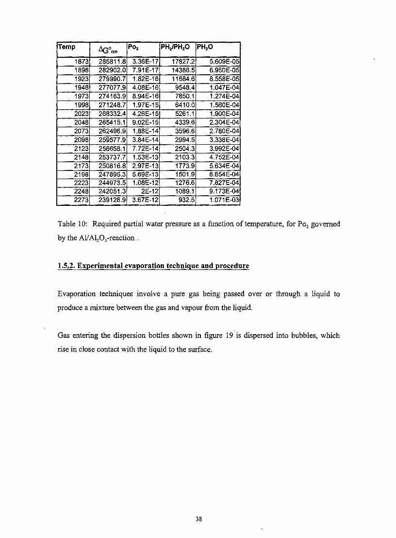
Table 10 gives the required water vapor partial pressure in hydrogen if the oxygen
fugacity in the industrial smelting process is governed by the All Alz0 3-reaction
According to Belton (1998) the lowest waterhydrogen ratio which have been used
successfully was 0002 The problem with lower ratios is that the equilibrium can only be
approached practically from one direction because of the low oxygen capacity of the gas
mixture One should keep in mind that the approximations of the oxygen activity
governed by the All Alz0 3-equilibrium is based on the assumption that Al in
ferrovanadium behaves like aluminium in dilute iron alloys Performing an equilibrium
run at the ultra-low waterhYdrogen ratios at a corresponding industrial slag basicity to
see if the same vanadium content can be obtained can test the validity of this assumption
Ifnot the waterhydrogen ratio can be adjusted accordingly
Although very low oxygen partial pressures can be attained certain complexities are
introduced specially referring to the gas mixing apparatus With H2-H20 mixtures
hydrogen is saturated with water vapour by passing it through distilled H20 or any other
liquid substance with a well-known water partial pressure (as function of temperature)
The vapour pressure of the water is only temperature dependent while the total gas flow is
also pressure (total pressure above solution surface) dependent resulting in a complex
system The gas mixing apparatus will be discussed in more detail in the next section
37
Temp ~ol)(n P02 PHlPH2O PH20
1873 2858118 336E-17 178272 5609E-05 1898 2829020 791E-17 143865 6950E-05 1923 2799907 182E-16 116846 8558E-05 1948 2770779 408E-16 95484 1047E-04 1973 2741639 894E-16 78501 1274E-04 1998 2712487 197E-15 64100 1560E-04 2023 2683324 426E-15 52611 1900E-04 2048 2654151 902E-15 43396 2304E-04 2073 2624969 188E-14 35966 2780E-04 2098 2595779 384E-14 29945 3338E-04 2123 2566581 772E-14 25043 3992E-04 2148 2537377 153E-13 21033 4752E-04 2173 2508168 297E-13 17739 5634E-04 2198 2478953 569E-13 15019 6654E-04 2223 2449735 108E-12 12766 7827E-04 2248 2420513 2E-12 10891 9173E-04 2273 2391289 367E-12 9325 1071E-03
Table 10 Required partial water pressure as a function of temperature for P02 governed
by the Al A120 3-reaction
152 Experimental evaporation technique and procedure
Evaporation techniques involve a pure gas being passed over or through a liquid to
produce a mixture between the gas and vapour from the liquid
Gas entering the dispersion bottles shown in figure 19 is dispersed into bubbles which
rise in close contact with the liquid to the surface
38
Very low oxygen pressures as in this study can be obtained with the following dynamic
methods
bull Saturation of hydrogen with water vapour by passing it over or through an ice bed
bull By passing hydrogen through a saturated salt solution eg Lithium chloride solution
(Chipman1953)
bull The amount of water vapour can be fixed by contacting the hydrogen gas with a
SUlphuric acid solution at a controlled temperature
bull Using the oxalic acid dihydrate oxalic acid equilibrium (Belton1998)
The application of ice is limited by very slow kinetics and very intimate contact between
the ice and the hydrogen gas must be obtained A further drawback is difficulty in
controlling and measuring the ice temperature to maintain a constant gas composition
throughout an experimental run
According to Belton(1998) early workers very precisely established the water vapor
pressure of oxalic acid dihydrate oxalic acid mixtures and obtained
Log P (mm Hg) 18053 - 96611(T + 250) (30)
With
T = Temperature (K)
At a temperature of 273K waterlhydrogen ratios as low as 00005 can be conveniently
obtained using the oxalic acid dihydrate oxalic acid equilibrium
The application of sulphuric acid as solvent enables better temperature control by
immersion of the contactors in a well stirred bath but the constant removal of water from
the sulphuric acid leads to the alteration of gas composition with t~me The time
dependence can be estimated by means of dynamic mass balance calculations
40
The partial water vapour pressure as a function of temperature and solution composition
can be obtained by fitting curves to experimental data given in Perry et al (1985) The
temperature-composition dependance of the partial water pressure temperature range 30
- 60degC and 70 -85 sulphuric acid solutions is represented by the following equation
PH2o(bar) = (-3372 +02584 T - 000616 T2 +5017105 T3) + (01449 - 0011 T
+2628 10-4 T2 -2122106 T3) H2S04 + (0002068 + 156910-4 Tshy
3736lO6-r2 + 2972108T3) ( H2S04)2 + (98106 -74107 T +
17108 T2 + 1389 1010 T3 ) laquo H2S04)3 (31)
with
T =Temperature (K)
Using this information and a simple mass balance the change in solution composition
with time can be estimated This was performed by calculating the amount of water
stripped out of the saturator for a given period assuming equilibrium between the water in
the sulphuric acid and in the gas stream The composition of the sulphuric acid was
recalculated after each period The calculations were repeated utilizing the new
composition of the SUlphuric acid and equation 31 to calculate the amount of water
stripped out of the saturators for the next incremental period The values used in this
calculation depicted in figure 20 are as follows
Initial sulphuric acid composition 80
Temperature of water bath 36degC
Mass of solution 2025 g
Total pressure above contactor 087 atmosphere
Gas flow rate 018Nm3min
Equilibration temperature 1700degC
41
102E-14
1E-14
--E 98E-15 IU -0
D 96E-15
94E-15
92E-15 +I__-__--_---r-__-__--_---__--__~_ _J
a 100 200 300 400 500 600 700 800 900
Contact time(hour)
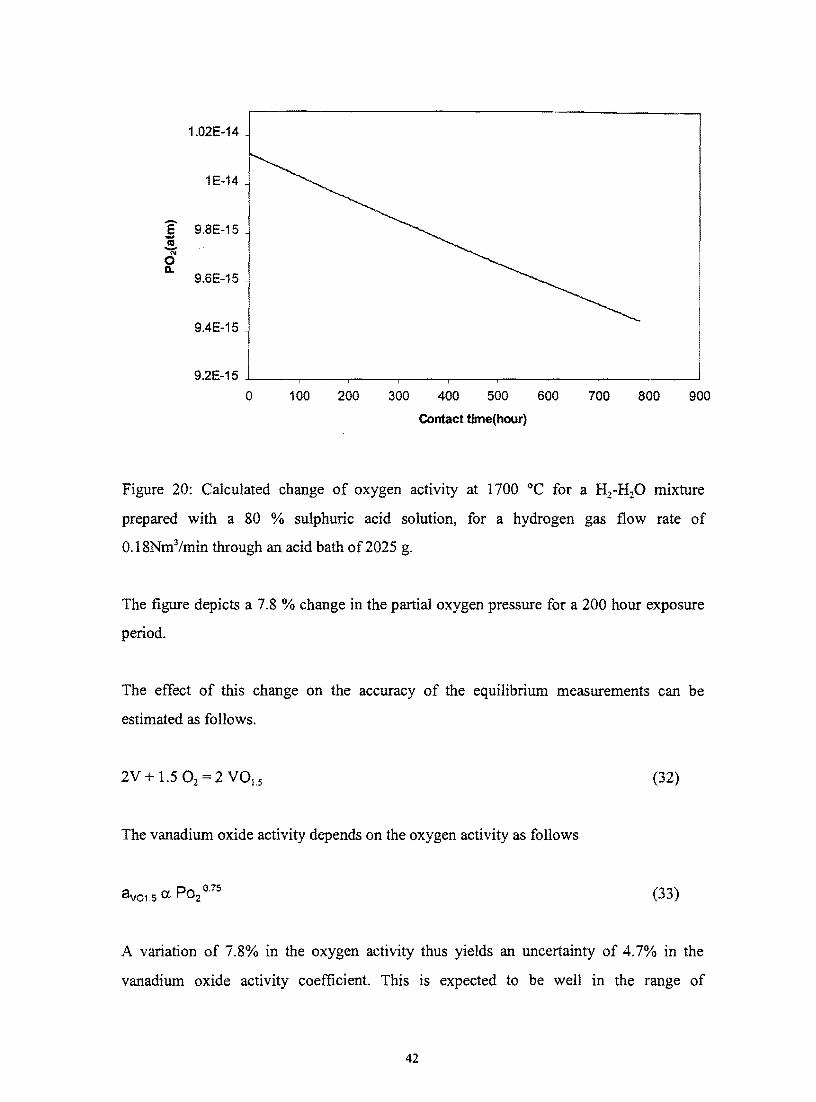
Figure 20 Calculated change of oxygen activity at 1700 degC for a Hz-HzO mixture
prepared with a 80 sulphuric acid solution for a hydrogen gas flow rate of
018Nm3min through an acid bath of2025 g
The figure depicts a 78 change in the partial oxygen pressure for a 200 hour exposure
period
The effect of this change on the accuracy of the equilibrium measurements can be
estimated as follows
2V + 15 O2 = 2 VOLS (32)
The vanadium oxide activity depends on the oxygen activity as follows
8 V01 5 ltX P02 075 (33)
A variation of 78 in the oxygen activity thus yields an uncertainty of 47 in the
vanadium oxide activity coefficient This is expected to be well in the range of
42
experimental errors indicating that the sulfuric acid needs only be replaced every 200
hours
The temperature of the water bath in which the saturators are immersed should be
carefully controlled because the water vapor pressure over the solvent depends
exponentially on the temperature as indicated by figure 21
300E()2
250E()2
200E()2
I --shy
C co
D 150E()20
N z a 100E-02
500E()3
~ OOOE+OO
o 20 40 60 80 100
Temperature of aqueous sulphuric acid solution(degC)
Figure 21 Effect of temperature on the partial water pressure above a 85 sulphuric acid
solution (Perry1985)
A circulating water bath with a controller will ensure uniform temperatures where a
number of saturators are used in series To prevent alteration of the gas mixture being
used all the gas-carrying tubes must be heated to prevent condensation Minu et al(1948)
reported tube temperatures around 80 dege for a mole fraction water in the gas stream of
0175 to prevent condensation
All the adjustable parameters should be carefully controlled if accurate results are to be
obtained
43
153 Kinetics of the vanadium oxidation reaction
The overall reaction can be divided in a number of steps taking place in series The first
step is the mass transfer of H20 as a gas across the boundary layer to the gas-slag
interface The second step is the actual chemical reaction of H20 at the the gas-slag
interface by adsorption and reaction with the slag phase The next step entails the mass
transfer of the absorbed species to the slag-metal interface Another chemical reaction
takes place at this interface whereby vanadium is oxidized The step following the
oxidation reaction is the mass transfer of the vanadium oxide from the interface to the
bulk of the slag increasing the average vanadium content in the slag The slowest of these
steps will govern the overall rate of the overall reaction
Chemical reactions are activation energy controlled remaining close to equilibrium at high
temperatures Thus mass transfer may be the rate-limiting step The purpose of this
discussion is to evaluate the mass transfer of water to the slag-gas interface as a possible
rate-determining step Unfortunately not much is known about the diffusion of vanadium
species in slags
If the rate of the overall reaction is determined by the rate of mass transfer of H20 to the
interface then the rate of water vapor diffusion can be expressed according to the
following reaction
(34)
The rate of vanadium oxidation(molfhr) is 066 times the rate of mass transfer of H20 to
dNHOthe interface In this equation is the rate of mass transfer of H20 to the interface 2
dt
and m is the mass transfer coefficient
Assume C =0 and PH 0 is smaller than 01 atmosphere (Nagasaka 1994) then 2
44
(35)
With R the universal gas constant T the temperature in K and p~ the partial water
pressure of the bulk gas phase
Assume the following oxidation isotherm for vanadium
006 --------------shy
004 ~ 0 gt RateBX
002
000 -f-------i--------i-----+__
o 2 4 6
t (h)
Figure 22 Assumed vanadium oxidation isotherm
Six hours is the assumed duration time for each experimental trial to reach equilibrium at
a given temperature It is further assumed (based on industrial slags) that the equilibrium
mole fraction vanadium is 006 Two oxidation rates are now considered Rate A (the
initial rate) and Rate B (the average oxidation rate) See figure 22
Fluid dynamics calculations for a specific experimental setup can evaluate the mass
transfer coefficient(m) in equation 34 Mannion et al(1991) and Nagasaka et al(1993)
used these equations to good effect to investigate gas mass transfer control in reactions
where the chemical reactions were sufficiently fast The experimental setup of this study
correlating with their studies is as follows
45
dSh= mshy (38)
D
With
d = diameter ofnozzle (m)
r = radius of crucible (m)
= viscosity (pas) ~
p = density (kgm3)
D = interdiffusivity (m2s)
u = linear velocity (m1s)
m = mass transfer coefficient(m1s)
Using the gas properties of interest the dimensionless Reynolds (Re) and Schmidt (Sc)
numbers can now be calculated as in equation 39 and 40 respectively
Re= dup (39) Ji
Sc=L (40)pD
Because of the low PHp needed (see Table 10) the gas mixture can be considered to be
pure H2 and the gas properties of H2 are shown in Table 11 for a gas temperature which is
the average of the slightly preheated gas (330K) and the metal surface (1973-2123K)
Properties ofH2(1200K)
p 00176 kgm3 (calculated using ideal gas law)
~ 0000024 Pas (Fruehan1998)
D 997 10-4 m2s (Szekely1971)
Table 11 Properties of H2 at 1200 K
47
The values used in the calculation are shown in Table 12
Values used in calculations
Slag mass 00002 kg
Molar mass of slag (CaO Al203 11) 0079 kgmol
Mole slag 000253 mol
Total pressure 0876 atm
Bulk Pmo 00004101300 Pa
Table 12 Values of constants used to perform the calculations
In addition to the value ofD reported by Perry et al(1985) to be 997 cm2s it may also be
calculated using the empirical equation also proposed by Perry et al(1985)
(41)
where
T = temperature in K (1200K)
P = pressure in atmosphere
D = interdiffusivity
MAMa = molar mass of specie A and B respectively
L VA L VB = Atomic diffusion volumes
Table 13 shows atomic diffusion volumes of some of the gases found in metallurgical
processmg
48
Specie atomic diffusion volumes
H2 707
I N2 179
O2 166
Air 201
CO 189
CO2 269
H2O 127
S02 411
Table 13 Atomic diffusion volumes for use in estimating DAB (Perry et al1985)
The gas diffusivity ofH20-H2 was calculated to be 1008 cm2s at 1200 K using equation
41
The two correlations used to calculate the minimum gas flow rate needed to maintain the
oxidation rates showed in figure 22 resulted in slightly different results as seen in Table
14
Mannion Nagasaka
Gas flow rates(mllmin) Gas flow rates(mllmin)
Oxidation rate A 141 10-7 molls 4015 5065
Oxidation rate B 703 10-9 molls 43 542
Table 14 Results of fluid flow calculations for different oxidation rates Flow rates are for
25degC and 0865 atm pressure
Darken et al (1945) have established that approximately 09cmls (106 mllmin through a
tube ID 5mm) is an optimum linear flow rate through a cylindrical tube to minimize
thermal diffusion and temperature uncertainties
It is evident from the results that very low flow rates are sufficient for an assumed
oxidation rate if gas mass transfer is the rate-determining step (rate B) Thus the gas mass
49
transfer does not have a profound effect on the kinetics of the oxidation rate and should
therefore not be the rate determining step One of the other reaction mechanisms proposed
could therefore be rate limiting
16 Conclusion
It can be concluded that the A120 3 content of the slag ( or slag basicity) has a strong effect
on the amount of oxidic vanadium in the slag In addition to this the amount of
vanadium in metallic form is also dependent on the slag basicity Both of these
mechanisms of vanadium loss to the slag should be quantified in order to maximize
vanadium recovery The oxidic vanadium loss to the slag can be quantified by performing
high temperature equilibrium experiments utilizing hydrogen-water mixtures to fix the
oxygen activity
50
2 Experimental technigues
21 Introduction
Little infonnation is available on activity-composition relations of vanadium in contact
with high AI203-CaO-MgO slags as indicated by the previous section Although metal
droplet entrainment has been identified as one of the possible mechanisms of vanadium
loss to the slag this section will concentrate solely on the quantification of the effect of
the slag basicity on soluble vanadium loss to the slag The experimental technique
involved the equilibration of synthetic CaO-AI20 3 slags with a vanadium crucible by
maintaining the required oxygen activity using H2-H20 gas mixtures After equilibration
the slags were quenched polished and analysed using energy dispersive X-ray analysis
(EDX) techniques Knowing the mole fraction ofV015 in the slag and the mole fraction of
water in the reaction gas the vanadium activity coefficient YV015 was detennined for a
range ofCaOIAlz0 3- ratios
22 Experimental set-up
221 Gas system set-up
As indicated previously ultra-low oxygen activities based on the assumption that the
oxygen activity in the industrial smelting furnace is fixed by the AlzO Al- equilibrium
can only be obtained using hydrogen gas equilibrated with water vapour The amount of
water vapour was fixed by contracting hydrogen gas with 757 sulphuric acid at a
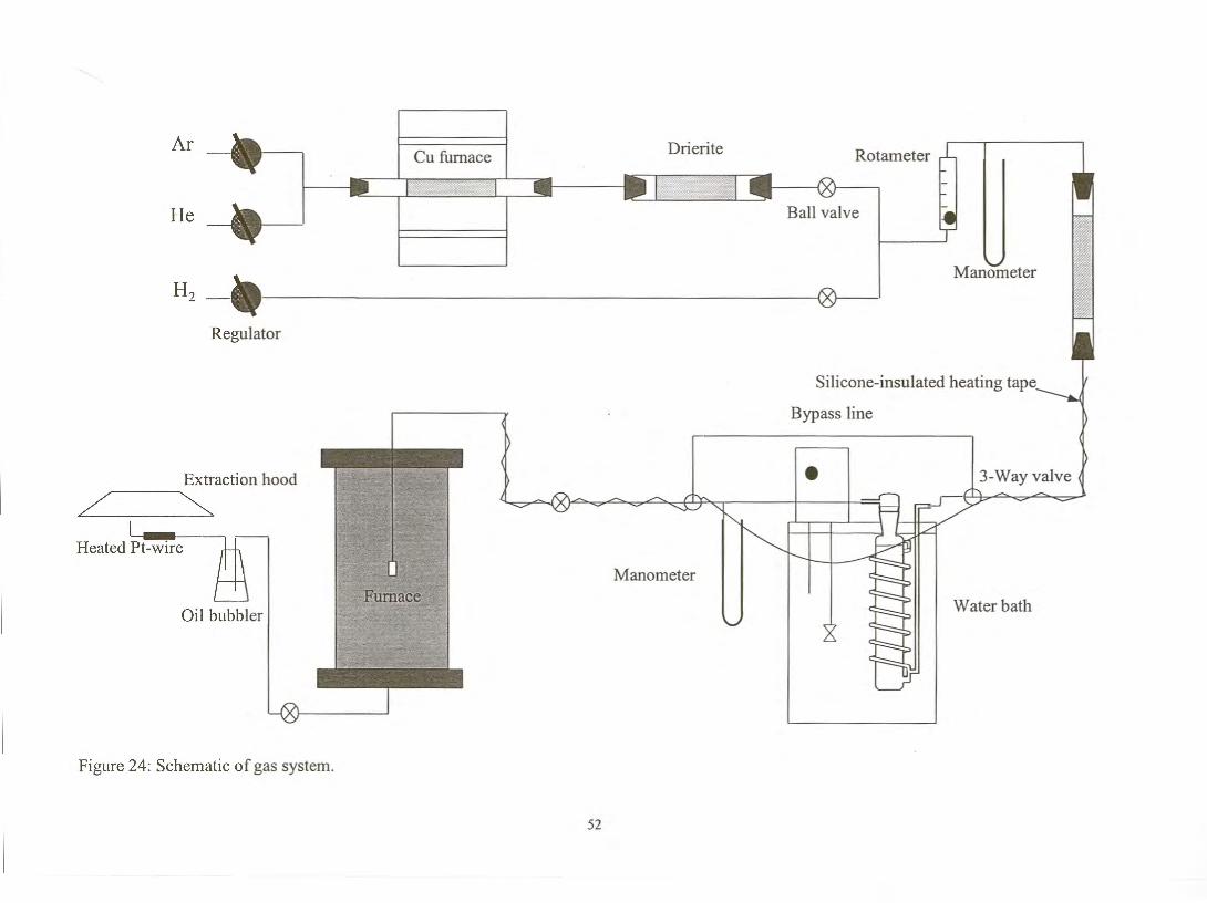
controlled temperature of 42plusmnOl 0c A schematic representation of the gas system is
depicted in figure 24 while figure 25 shows the complete experimental set-up used in the
present study
51
drop of llcm Hg over the reactors was observed Although a dense polymer the Tygon
could not prevent gas from diffusing out resulting in a pressure drop within the gas line
when not in use causing the withdrawal of sulphuric acid from the reactors into the
tubing Attack of the tubing was prevented by keeping the reactors pressurised between
experimental runs
Each reactor contained about 05 dm3 of sulphuric acid solution The amount of water
vapour in the gas stream was originally fixed by contacting the hydrogen gas with 85
sulphuric acid at a controlled temperature of 60 plusmn 01 0c The first equilibrium run served
the purpose to test the assumption that the activity of Al in FeV is similar to that of Al in
dilute steel This assumption was originally made in order to perform calculations to
estimate the oxygen potential in the industrial smelting process Results obtained will be
discussed in more detail later in this work (See section) Before this experiment could be
performed checks had to be performed on the exist gas composition to determine the
consistency as well as the deviation from equilibrium as been depicted by figure 29
57
0082 0084 0086 0088 009 0092
Weighed mass of water (g)
Figure 29 Comparison between the actual mass of water transported by the gas stream
and the mass of water calculated assuming equilibrium between the water vapour in gas
stream and acid Calculations were performed for a 85 sulphuric acid solution kept at
60degC Gas flow rate of 018 NVmin and total pressure 0877 atm were used Tabulated
correlations in Perry et al (1984) of the partial water pressure as a function of temperature
and acid composition were also implemented Values are for different times of gas flow
ranging from 19 to 24 hours
Figure 29 shows that the amount of water in the reaction gas deviates considerably from
the equilibrium calculated amount thus indicating that the eqUilibrium could not be
obtained within the saturators In any case equilibration of the lime-alumina slag with a
vanadium crucible under this atmosphere caused a low vanadium oxide contact (of only
1) compared with the 3 in plant slag Because of too reducing condition the 85
sulphuric acid solution was replaced by a 75 sulphuric acid solution at a controlled
temperature of 42 plusmn 01 degC The equilibrium partial water pressure above the surface of the
sulfuric acid was thus increased by 27 times The composition of the sulphuric acid
solution was monitored prior to filling of the columns by measuring of the density of
sulphuric acid solutions The density measurements were performed by immersing a piece
of 316 stainless steel plate the volume of which was accurately pre-determined
(3372cm3) into the sulphuric acid solution at a known temperature After immersion the
0126
0124
--9 0122
D 1 012
0118t5 (fJ
~ 0116 E
0114 16 5 0112()
a 011
0108
y= 19419x- 00513 bullR2=09948
58
flat plate was weighed accurately to three decimal places to measure the decrease in
weight due to the buoyancy force acting on the flat plate On average the mass readings
showed around 10 mg decrease due to the corrosion of the stainless steel in the SUlphuric
acid solution from the moment the reading stabilised until the reading was recorded The
density of the sulphuric acid can be calculated using the equation 45
Weight of flat plate before immersion- Weight of flat plate after immersion PH2SO4 Volume of flat plate
With PH so density of sulphuric acid (gem3)
2 4
(42)
A variation of 0010gl3372 em3 yields an uncertainty of plusmn 003 in the density of the
sulphuric acid
Accurate tabulation of sulphuric acid densities as a function of temperature and
composition is found in literature (Perry (1984))
59
To ensure that conditions proceed as close as possible to equilibrium between the water
vapour in the gas stream and acid three glass reactors containing a helical gas-liquid
contractor were employed in series One such reactor is depicted in figure 30
gas in
acid level
gas out
helical gas-acid contactor
Figure 30 Glass contactor containing sulphuric acid showing the path of the carrier gas
The stainless steel tubing was protected from possible acid attack by using glass traps at
the inlet and outlet of the sulphuric acid contractors as depicted in figure 31 The glass
reactor preceding the water bath was dried at 200degC to ensure no gas stream
contamination during its exposure to the atmosphere when the sulphuric acid was
replaced Concentrated sulphuric acid attacks 316 stainless steel tubing and precautionary
measures had to taken against sharp pressure fluctuations which may cause acid reaching
the tubing
60
anhydrous CaS04-filled column to remove any water A second anhydrous CaS04-filled
column was inserted just after the rotameter to remove any excess water entering the
system through the hydrogen At the outlet from the furnace the hydrogen gas was burnt
on a heated platinum wire after passing through an oil trap Figure 32 shows the heated
Pt-wire assembly
Heated Pt-wire
Aluminium cooling fm
Solid alumina rod
To power source
Gas flow direction
To power source
Figure 32 Heated platinum wire assembly
The platinum wire assembly proved to be a safe alternative to the traditional bunsen-flame
method of oxidation of hydrogen gas The platinum wire was kept at around 1000 degC
for weeks on end without failure This enables experiments to be safely carried out
throughout the night if no power failure occurs The completeness of the oxidation
reaction was determined by holding a hydrogen detector in the close vicinity of the heated
platinum wire No traces of excess hydrogen could be detected around the platinum wire
As can be indicated by the figure the Pt-wire was wound around an alumina tube that
fitted snugly into a larger alumina tube which directed the hydrogen gas through the small
opening between the two tubes onto the hot Pt-wire This ensured intimate contact
between the hydrogen gas and the Pt-wire
Gas flow rates were measured and controlled by a single rotameter which was calibrated
in-line using a bubble meter In-line calibration of the rotameter was required to establish
the exact flow rate of the gas mixture because a back pressure in the gas line does affect
62
--
the flow rate For this calibration purpose the outlet from the oil trap at the end of the gas
system was connected to the bottom of bubble meter cylinder The gas was introduced
into the bottom of the apparatus displacing a soap bubble along the length to the top end
of the cylinder A stopwatch was used to establish the time required for one bubble to
traverse the indicated volume This measurement was repeated around 20 times to
establish a good average value for each rotameter setting
During actual equilibration runs the hydrogen flow rate was kept at 018 Ndm3fmin
throughout Because equilibrium between the water vapour in the gas and acid can not be
assumed the actual amount of water in the gas was monitored (between equilibration
runs) by passing the humid gas stream through a Drierite-filled column for a period of 5
hours The mass increase was weighed accurately to the nearest milligram The 5 hour
exposure period yielded a typical mass increase of 85 mg Figure 33 depicts the actual
mass of water transferred per unit time as a function of the total time that the sulphuric
acid reactors were in use
0019
bull
Q)
1sect 0018 Q) - bullL s
4E -0 0017 bull bull bull bull bull U) bullCIc ~ I
C) 0016 L --~ 0015 ~
0014 o 50 100 150 200 250
Cumulative saturation period
Figure 33 The actual mass ofwater measured per unit time as a function of the time the
sulphuric acid reactors were in use
63
As indicated by figure 33 no appreciable change in the water content of the reaction gas
due to stripping of water out of the sulphuric acid occurred during the 200 hour saturation
period
The reliability of the measured mole fraction of water vapour depends on the accuracy of
the weight measurements A three-digit scale is in effect only accurate to two decimal
places The weighing practice was kept as consistent as possible to increase the reliability
of the measurements The resulting average calculated mole fraction of water vapour in
the gas stream was (200 plusmn 005) x 10-3 for the equilibrium runs In one experiment the
mole fraction water vapour in the hydrogen gas was increased to (352 plusmn 002) x 10-3 to
determine the oxidation state ofvanadium in the slag
Leak detection was performed before each equilibrium run by filling the gas line with
pressurised Helium gas (pressures around 12 cm Hg were applied) and checking for leaks
with a hand-held helium detector Leak checks performed on the furnace itself will be
discussed later this section
The line pressure before and after the water bath was measured using mercury
manometers The pressure above the acid solution is important for calculating the actual
as well as equilibrium amount of water (mole fraction) in the hydrogen stream Figure 34
compares the actual amount of water transferred with the equilibrium amount of water
(calculated using the following values and equation 25 in the literature section)
Acid composition 757 H2S04 (determined from density measurements)
Water bath temperature See appendix 1
Exposure period to acid reactors See appendix 1
Gas flow rate 018 NlImin
Total pressure above acid solution 0877 atmosphere
64
06
-C)- 05 L
~ ro ~- 04 0 () () 03 ro E C 02 ~ ro J () 01 ro 0
0 0 01 02 03 04 05
Weighed mass afwater (g)
Figure 34 Comparison between the actual weighed mass of water and mass of water
calculated assuming equilibrium between water vapour in the gas stream and the acid
As figure 34 shows checks performed on the exit gas composition using Drierite-filled
columns show a definite deviation from the calculated water content of the reaction gas
(calculated assuming equilibrium between the water vapour in the reaction gas and the
sUlphuric acid solution) The amount of water in the reaction gas is consistently lower
than the predicted content indicating that three reactors in series are not capable of
obtaining the equilibrium water content in the reaction gas
The slopes of the straight lines fitted through the data points in figure 29 and 34 indicate
that the system utilising a 75 SUlphuric acid solution is closer to equilibrium than the
system utilising a 85 sulphuric acid solution It is thus easier to obtain equilibrium
between the water vapour in the gas stream and the acid if the lower concentration
sulphuric acid solution is utilised
The reactors were designed at first with helical contactors measuring a total length of
around 6 meters to ensure long intimate contact between the reaction gas and sulphuric
acid solution Despite obvious measures to ensure equilibrium at the end equilibrium
y = 12616x - 00239 R2 =09919
65
could not be obtained This underlines the fact that checks on the exit gas composition
between equilibrium runs are absolutely essential Any published data based on HlH20shy
equilibrium utilised to fix the oxygen activity should contain the method used to
detennine the gas composition An assumption that equilibrium conditions prevail in the
saturator may decrease the value of the work It can further be concluded that the water
content of the reaction gas can be successfully monitored using Drierite as absorbent
The sulphuric acid solution (after more than 200 hours exposure period) was replaced
after the completion of the first series of experiments investigating activity-composition
relations Table 15 shows the calculated composition of the sulphuric acid in the reactors
before and after the completion ofthe experiments
Initial Composition Final composition
First reactor 757 755
Second reactor 757 752
Last reactor 757 752
Table 15 Change in sulphuric acid composition (mass percentages)
It is evident that no appreciable change of the sulphuric acid composition occurred and
that 200 hours exposure with 3 reactors containing 05 dm3 acid can comfortably maintain
a constant water vapour level in the hydrogen gas
222 The furnace set-up
A schematic representation of the furnace assembly set-up is shown in figure 35
66
AI20 3 rod (Top gas inlet)
~ L J t
1shy~ ~ -
I +shy -- - r- L-shy
)
I l
-
I X V
g il J
~ ~
Rubber stopper Water-cooled copper end cap Rubber gasket Stainless steel hooks Water inlet Pt-wire Pt-discs
Fiberboard clamp Heating elements
Heat insulation
Top radiation shield
Alumina work tube
Bottom radiation shield
Furnace shell
Fiberboard clamp Spring
Rubber O-ring Gas exit tube Water-cooled copper end cap Plastic membrane
Figure 35 Schematic representation of the furnace assembly set-up
67
The vertical tube resistance furnace from Pirotherm which employed six equidistant
molybdenum disilicide-tungsten carbide heating elements situated around the furnace
tube was utilized The specified temperature rating of the furnace is maximum 1800degC
for normal heating and cooling cycle If necessary the furnace could reach 1850degC
whereafter the elements should never be switched off and kept at or above 900degC
indefinitely
The maximum temperature that could reliably be obtained in the available laboratory
furnace without drastically reducing the life of the elements was 1700degC To test the
temperature influence on the activity coefficient of vanadium an experiment was
conducted at 1750degC Due to severe Si02 pick-Up in the slag no more experiments were
performed at this temperature A single run at 1650 degC was performed to test the influence
of temperature on the activity coefficient ofvanadium
The furnace temperature was controlled by an Eurotherm controllerprogrammer using a
Pt-40RhlPt-20Rh thermocouple that was positioned next to the furnace tube close to
the hot zone The exact position and temperature of the hot zone was measured with a
hand-held Pt-40RhlPt-20Rh thermocouple (Bedford1965) placed at various depths in
the furnace tube During this procedure the lower end of the alumina tube was covered
with a plastic film to prevent an updraft of hot air through the furnace tube leading to
inaccurate measurements The temperature profile as a function of position at a
programmed temperature of 1600degC is shown in figure 36
68
Hot zone
-
1620 1600
1580 0 1560li2 e I 1540 e (I) 1520 c E 1500 ~ 1480
1460 1440
40 45 50 55 60 70 75 80
1---0 ~ bull I
~ I
J r j
65
~--
Depth(cm)
Figure 36 Temperature profile as a function ofposition Depth measured from top of
alumina tube Programmed furnace temperature 1600degC the furnace hot zone was
determined to be 50 mm in length The average measured temperature in this zone was
(1601plusmn05 degC )
The average temperature of the hot zone measured with the hand-held thermocouple was
within 1degC of that indicated by the furnace controller
The re-crystallized alumina (998 AI20)) furnace tube (length l2m OD 75 mm and
ID 65 mm) was fitted with water-cooled copper heads at both ends The bottom fitting
extended below the alumina tube and was sealed with O-rings lubricated with high
temperature vacuum grease The upper end cap was sealed before each equilibrium run
to the open flat end of the tube sealing with a rubber gasket between the tube and the
fitting A steel bracket attached to the furnace tube exerted pressure on the gasket The
upper end cap contained the rubber plug sealed to the fitting to prevent gas leakage due to
the high pressure within the work tube The rubber plug was used as exit seal for the three
alumina tubes used to suspend the vanadium crucible inside the tube and to introduce gas
to the synthetic slag The tubes were sealed to the rubber plug with silicone sealer
69
Possible thermal damage (by radiation from the hot zone) to the rubber plug and silicone
sealant was prevented by using two round Pt discs fixed to the alumina tubes using Ptshy
wire The Pt-disc diameters corresponded to the inside diameter of the alumina tube
which formed part of the upper radiation shield No thermal damage whatsoever was
observed at the surface of the rubber plug
Radiation shields were present within the furnace tube above and below the crucible The
purpose of top radiation shield was to protect the elements as well as copper end cap from
excessive temperatures The top radiation shield was suspended from the water cooled
end cap using 05 rom OD Pt-wire
Failure of the vanadium crucible during the first equilibrium run due to complete melting
was found to be the result of severe phosphorus pick-up The radiation shields consisted
of fibreboard rings made from a high-temperature fibreboard temperature rating of
1800degC and glued together using high temperature cement The cement originally used to
manufacture the radiation shield was an alumina-phosphate cement Under reducing highshy
temperature conditions the cement can be reduced to Al20 3 and P2 (gas) The phosphorus
gas apparently alloyed with the vanadium crucible to form a low melting point eutectic
component resulting in failure at a temperature 200degC below the melting point of pure
vanadium The radiation shields were reconstructed using the same high-temperature
fibreboard rings and pure high-temperature alumina cement Following severe silica pickshy
up in the slag within the crucible during early runs these radiation shields were found to
contain mullite which can be reduced to Al20 3 and SiO(g) under reducing highshy
temperature conditions employed here In support of this mechanism silica crystals were
observed on the cooler regions of the radiation shields The continuous precipitation of
silica onto the gas carrying alumina tube over extended periods led to failure of the tube
due to glass formation A glass phase could clearly be observed in the vicinity of the crack
formed in the alumina tube
The radiation shields were originally coated with a plusmn5 rom thick layer of alumina (98
AI20 3) applied as a slurry The alumina layer was subsequently sintered at 1400degC for at
least 8 hours in a muffle furnace The alumina coating and sintering cycle were repeated a
number of times if considered necessary after the radiation shield was examined for
70
large cracks Some cracking of the alumina coating did still occur during subsequent use
causing sporadic contamination of the samples by silica Those samples which showed
more than 2 silica (mass percentage) pick-up were discarded Silica pick-up was more
severe in siags with higher basicities presumably due to low silica activity coefficients in
these slags Furthermore there was a direct correlation between the creep behaviour and
the silica content of the slags Severe slag creep was observed in some early experiments
due to severe silica pick-up from radiation shields Slag creep was prevented to an extent
by reducing silica pick-up by coating the radiation shields machining two grooves into
the inner wall near the top ofcrucible and also by dividing the opening of the crucible into
two using a Olmm vanadium wire (See figure 38)
223 Quenching set-up
The lower-end of the furnace tube was sealed with a PVC membrane thickness of 30 I-Lm
wrapped over the furnace tube opening with a layer ofvacuum grease as sealant between
the copper end cap tube and the plastic film The PVC film was held in position by using
a hose clamp pressing onto a (01 mm-thick 20mm wide) PVC band preventing the thin
plastic film from being cut by the clamp
The PVC-covered end cap was immersed in water contained in an aluminium container
through which water ran continuously A large containerreservoir situated below the
aluminium container was continuously filled by the overflow of the top container When
the water level within the reservoir reached a certain height a pressure sensitive switch
activated a pump located at the bottom of the reservoir
The quenching set-up shown in figure 37 consisted of two single bore alumina tubes (ID
25 mm) containing molybdenum wires of 1 mm in diameter The bottom protruding
molybdenum wires were bent to form two hooks The top hole from which the thick wires
protruded (above the furnace tube) was sealed by silicone sealant The crucible was
suspended from the two molybdenum wire hooks by means of a thinner (03 mm
diameter) connecting molybdenum wire Solid-state diffusion is very much possible at
1700 degC and ultra-low partial oxygen pressures result in oxide-free contact surfaces
Solid-state welding occurred between the thick molybdenum hooks and the thin
71
The following chemicals were used to make up the slag mixtures shown in Table 15
before equilibration GP-grade V20 S (assay gt99) V (assay 999) CaCO) (assay
995) MgO (assay 98) and Al20 3 (assay 99) The first few experiments
concentrated on the effect of MgO on the amount of oxidic vanadium in slag
Unfortunately it was not possible to establish the effect of MgO under equilibrium
conditions No MgO originally added to the slag samples could be retained after
equilibration because magnesium has a significant equilibrium vapour pressure(See
section in literature study) It was subsequently assumed that MgO behaves similarly to
CaO in the industrial furnace on a molar basis (as far as the effect on VOx activity is
concerned) because both oxides show strong basic behavior in low basicity slags For this
reason the experimental work concentrated on CaO-AI20 3 slags
Due to the problem of hydration of the CaO in pure form high grade CaCO) was used as
source of CaO Calcination of the CaC03 was performed at 1200degC for 5 hours in a
muffie furnace heated by silicon carbide heating elements and using a Pt-crucible for
containment of the powder After calcination the calcium oxide was cooled in a water
free atmosphere by placing the Pt-crucible with the contents still at 1200~C directly into
a desicator Only a few minutes was allowed between the subsequent crushing of the CaO
pellet and the weighing of the powders to prevent any changes occurring in the
composition of the CaO
The Al2 powder was dried by heating at 800degC for 5 hours Samples (typically 20g) 0 3
were made up by weighing the required mass of powders on an electronic mass-balance
reporting the weight to the nearest milligram and mixing these powders thoroughly in a
swing mill for 5 minutes After thorough mixing the pellets (15mm diameter and 20mm
in height) were pressed and sintered for 3 hours at 1200degC crushed and re-mixed This
was followed by another pelletizing and sintering cycle According to need pieces ofO2g
were chipped from the pellet and enriched with vanadium by adding pre-determined
amounts of V20 S or metallic vanadium powder (particle size 5~m) to the chunks The
chunks with the vanadium additions were thoroughly mixed in a swing mill before
charging into the vanadium crucible The mixed powder was compacted to ensure the
maximum amount of reagents to be present within the crucible The crucible was filled to
75
just below the first groove which was machined into the inner wall The slag depth in the
crucible after melting was about 25 rnrn yielding a slag mass ofca 02g
232 Experimental run
The crucible containing the slag was introduced cold to the furnace then heated at
2degCmin to l400degC under purified argon The gas stream was switched to the hydrogenshy
water mixture at l400degC Subsequent heating to the equilibration temperature was at
lOCmin holding the sample at this final temperature for 6 hours before quenching Some
minutes before quenching the hydrogen-water mixture was replaced by purified Argon for
safety reasons After quenching the sample was retrieved from the water and the
perforated PVC membrane was replaced with a new layer of PVC with the furnace still at
the equilibration temperature Oxidation of molybdenum occurs even in deoxygenated
Argon at l700degC Hence after the replacement of the PVC membrane the Argon was
again replaced by hydrogen for the duration of the cooling cycle Prior to opening the
furnace was once more flushed with Argon The thick Molybdenum wires lasted for 5
equilibration cycles before needing replacement
233 Sample analysis
After being retrieved from the water the crucible with slag was dried for 10 minutes at
100degC The crucible was mounted in an epoxy resin (impregnated under vacuum)
Polymerization of the resin was performed at 90degC for 4 hours Following polymerization
the crucible was sectioned along its axis using a diamond cut-off wheel Despite using a
diamond cut-off wheel it still took half an hour to cut through the supposedly pure
vanadium crucible
From the XRD-pattem shown in Figure 40 the presence of vanadium nitride phases are
identified in the vanadium crucible after equilibration
76
A combination of relatively slow cooling due to the water vapour cloud surrounding the
crucible during quenching and the phase stabilizing effect of vanadium on the high
basicity slags (CaOAlz0 3 gt07) gave rise to formation of mUltiple crystalline phases The
high basicity slags (CaOAlz0 3 gt07) usually did not contain any entrained vanadium
metal particles
80
--
3 Equilibrium time determination
Two possible rate-determining steps were considered - gas-phase mass transfer (of H20 to
or from the gas-slag interface) and mass transfer ofV0ts within the slag To quantify the
former the correlation as used by Belton amp Belton (1980) was employed to find the mass
transfer constant of H20 in the gas No data on the diffusivity of vanadium cations in
CaO-A120 3 could be found but data for transition metal cations (Fe2+ Fe3+ and Mn2+)
were used to estimate the likely range of diffusivities (Verein Deutscher
Eisenhiittenleute1995) These data are given in Figure 44 with extrapolations to the
equilibration temperature of 1700degC From these data the diffusivity is estimated to be at
least 6x 1 010 m2s
1E-07 -------------
1E-08
II) -N 1E-09E Q
1E-10
1 E-11 -t------I-----t------I-----J---t------I
1500 1600 1700 1800 1900 2000
T (K)
Figure 44 Literature data on diffusion coefficients of transition metal ions in slags
similar to those used in this work Slag compositions are given as mass percentages
where A refers to A120 3 C is CaO S is Si02 and N is N~O The two data points
at the lower temperatures give the temperature range for which the data are reported and
the line to 1973 K gives the extrapolation to the temperature used in this work
81
Because of the low oxidizing capacity of the H20IH2 ratios implemented in this work
care had to be taken that equilibrium could be obtained from both sides Le both from
higher than equilibrium and lower than equilibrium vanadium oxide concentrations in the
slags
V01S mass transfer in the slag is possibly rate determining Vanadium metal powder was
charged in the initial mixtures to assist with the diffusion process by reducing the actual
diffusion distance which would have been 3mm if no powder was used (Le the radius of
the pure vanadium crucible) Thorough mixing was ensured by grinding of the chunks of
pellets with the vanadium or vanadium powder addition to a powder in a tungsten carbide
grinding vessel Another sample was loaded with vanadium oxide in the initial slag
mixture to determine if the same final vanadium content as in case of the sample
containing pure vanadium metal could be obtained All these equilibration runs were
conducted at a CaO Al20 3 ratio of 1 and at 1700 degC (See experiment 1 and 3 in Table 16)
The activity of oxygen was kept constant by using constant H20IH2 ratios The initial
assumption that 6 hours should be sufficient if slag-mass transfer is the rate-determining
step (for the lower band of the estimated diffusion) was confirmed by the two
experiments
82
006 - - - - - _bullo
Gas mass transfer control
004
002
- - ----- - - -
Slag mass transfer control D=6x1 0-10 m2s
000 __-------t-----L----t------+___
o 2 4 6
t (h)
Figure 45 Calculated change in the average V0l5 content of the slag for respectively gas
phase mass transfer control and slag mass transfer control (lower-bound estimate of
diffusivity) The data points give the actual change in vanadium content for a slag which
contained no vanadium oxide to start with (filled circles) and one which contained a mole
fraction of 0058 of vanadium oxide at the start of the 6-hour equilibration period at
1700degC
The same final vanadium oxide content in the synthetic slag was essentially reached
indicating that six hours should be sufficient to reach equilibrium In this case the
standard amount of vanadium pentoxide initially added to the synthetic slags
corresponding to a V0l5 mole fraction of about 006 happened to be very close to the
equilibrium leveL
83
4 Results and discussion
41 Activity coefficient relations
Table 16 gives a summary of all the experiments conducted containing the H20IH2 ratio
sample composition equilibration temperature and vanadium cation mole fraction as well
as the respective 95 confidence intervals (for analyzed vanadium mole fraction and
calculated basicity)
The activity ofvanadium oxide in the slag shown in Table 16 was calculated from the
equation 41 shown below
(41)
After completion of the experimental runs the crucibles were analyzed by EDX and was
found to be pure with no measurable aluminium pick-up Hence the activity of vanadium
in equation 41 was taken to be 1 The activity of water and hydrogen was fixed by the gas
mixture After analysing the the mole fraction of vanadium oxide in the slag the activity
coefficient ofVOu was calculated from equation 42
(42)
In this calculation the mole fraction of vanadium oxide in the slag (XV015) was
determined from EDX analysis of the amounts ofCa2 + A13
+ and V3 + in the slag by taking
species which make up the slag to be CaO AlOu and V015Hence the experimentally
determined activity coefficients ( YYOu ) also refer to this convention
84
Experiment Temp K
moisture (gth)
XH20 PH20
(atm) K aV015 111 95
Confidence limit
YV015 Basicity 95
confidencel limit
1 1973 170E-02 197E-03 172E-03 826477 0721 624E-02 0214 1154 090 0009 i
2 1973 170E-02 197E-03 173E-03 826477 0724 774E-03 0129 9352 064 0013 3 1973 176E-02 204E-03 179E-03 826477 0762 579E-02 0208 1317 101 0014 4 1973 172E-02 199E-03 175E-03 826477 0735 869E-02 0975 846 170 0021 o 1973 169E-02 196E-03 171E-03 826477 0715 728E-02 0397 982 113 0015 6 1973 168E-02 195E-03 171E-03 826477 0712 623E-03 0067 11424 062 0004 7 1973 168E-02 195E-03 171E-03 826477 0712 221E-02 0096 3217 063 0004 ts 1973 303E-02 351E-03 308E-03 826477 1717 169E-02 0158 10183 070 0015 Y 1923 00156 181E-03 158E-03 1165617 0895 742E-02 0128 1207 100 0044 10 1923 00151 175E-03 153E-03 1165617 0853 937E-02 0699 910 147 0009
Table 16 Summary of experiments performed
Before any activity-composition calculations could be performed the oxidation state of
vanadium should first be determined For a first approximation the oxidation state of
vanadium can be estimated by plotting the oxygen activity as a function of temperature
for different vanadium metal and oxide equilibria (Unit activities of oxide species are
assumed) In this case the equilibrium constant for the different vanadium metal and
oxide equilibria was calculated using the correlations ofKubas chew ski et al (1992) for the
free energy values At this stage it should be noted that there appears to be a serious
discrepancy between the literature values for the free energies of the vanadium oxide
species For example the Kubaschewski et al correlations predict the free energy of solid
V20 3 to be -1649 244 Jmole whereas the FACT database yields a value of -1673 483
Jmole This substantial difference - largely due to the difference in the entropy values shy
changes the equilibrium constant K2 (see table 17) by a factor 21 (being larger if the
FACT values are used)
85
v + 15H20 = V0IS + 15H2 15
aVO PHK = U 2 log K =-1 8258 + 113311T2 15 2
aV PHzO
2Al + 2VOU = Alz0 3 + 2V 2aA10 aVK3 = 2 2 J 2 log K3 = 40365 - 25570lT
aA1 avou
Table 17 Equilibrium constants germane to this work
(Correlations fitted for the temperature range 1600degC to 1850degC temperature in Kelvin
for the correlations reference states are pure solid V V20 3 and Al20 3 pure gaseous H2
and H20 and pure liquid At)
The data point shown in figure 46 indicates the average oxygen activities and the
equilibration temperature used to determine the influence of slag composition on the
activity coefficient of vanadium oxide As indicated the divalent oxidation state of
vanadium was expected to be stable for unit activities
86
1 01
001
0001
00001
1E-05
1E-06 - 1E-07E ((]-N
1E-08
a a 1E-09
1E-10
1 E-11
1E-12
1E-13
1E-14
1E-15
1E-16
V20 5
V20 3
V20 3
2210middot13 C 111014 )
-- VO
1850 1900 1950 2000 2050 2100 2150
Temperature(K)
Figure 46 Predicted oxidation state of vanadium Reference states were pure solid
VVOV2 and pure liquid V20 S and the correlations of Kubas chew ski et al (1992) were 0 3
used Data point indicates experimental conditions
By conducting an experiment at a higher oxygen activity and at constant basicity and
temperature the vanadium oxidation state can be determined more accurately This was
done by changing the water content of the gas mixture to 00035 mole fraction water
These results are presented by figure 47 which shows the predicted relative change of the
mole fraction of VOx in the slag as function of the relative change in the oxygen activity
for the different equilibria (Po2 = 20 X 1013 atm at 1700degC) The initial water vapour
content of 00020 yielded an initial mole fraction of VOx in the slag of 00077 (See
experiment 2 and 8 in Table 16) The data points on the graph present actual
measurements - indicating the best agreement between predicted and measured effects of
the change in the oxygen activity to be for the trivalent state
87
8 x o gt
6
4 V015
co VOt 2 c
0 0 1 2 3 4 5 6
P02
Initial P02
Figure 47 Expected and real vanadium oxide contents ofthe slag
The actual mole fraction VO as function of the CaOAl20 3 ratio is given in figure 48 for
experimental conditions as listed in table 16 The effect of the varying of the P02 was
taken into account during further analysis
88
12
10
80 gt ~ c
6 ~ 0
2 4
2
0
05 10 15 20
CaOAI2 0 3
Figure 48 Effect of slag basicity on VOx content for experimental conditions as listed in
Table 16
Nevertheless Figure 48 demonstrated the actual amount of soluble vanadium to be
strongly dependent on the slag basicity It is clear that in order to minimize vanadium
loses to the oxide phases the slag basicity should be as low as possible yielding at best
06 mole VOxat a basicity of 06 (for the P02 values used here)
The determined activity coefficient values ofV015 are illustrated in figure 49
89
120
~ 0100
80 0
~
60 gt shy
40
bull 20 ~shy~tIL___-_-
0 06 08 10 12 14 16 18
CaOAI2 ratio0 3
Figure 49 Calculated value of the activity coefficient of VO u in CaO-AI20 3 based on
equilibration runs at 1700degC under a hydrogen-water mixture with a water mole fraction
of 0002 (filled circles) The open circle (See experiment 8) is for a hydrogen-water
mixture (at 1700degC) with a water mole fraction of00035 and the triangle(See experiment
9) for 1650degC
Figure 49 demonstrates the activity coefficient of VOu to be strongly dependent on the
slag basicity with a sharp decrease in the activity coefficient at higher basicities The
measurement of the vanadium oxidation state is indicated by open circle in the figure
Furthermore the data point shown as a triangle indicates an experiment conducted at
1650degC As expected the activity coefficient is not strongly dependent on temperature
This indicates that the laboratory data - conducted at 1700degC - can be used to calculate
approximate equilibrium compositions at the furnace tapping temperature of 1840degC
The reliability of the measured activity coefficients depends on the reliability of the
equilibrium constant (which was discussed earlier) and of the gas composition and the
chemical analyses As far as the latter two are concerned the variation of plusmn25 in the
90
H20 content of the gas (as mentioned earlier) yields an uncertainty ofplusmn4 in the activity
coefficient (since avols is proportional to PH20IS) The largest 95 confidence interval on
the vanadium oxide content expressed relative to the average vanadium oxide content
amounted to 17 for the lower-basicity slags (with the lowest vanadium contents) and
11 for the slags with basicities higher than 07 This means that the maximum estimated
variability in the activity coefficients (assuming no systematic errors) is plusmn21 for the
lower-basicity slags and plusmn 15 for the higher-basicity slags The largest 95 confidence
interval on the analysed CaOAI20 3 molar ratio was 004 See Appendix 2 for the 95
confidence limits of the experimental results
From the viewpoint of the ferrovanadium producer it is clear that efficient recovery of
vanadium from the slag is favored by low basicity This can be achieved by lowering the
amount of CaO added to the furnace as burned time
91
5 Industrial slag sample investigations
51 Introduction
As indicated previously metal droplet entrainment has been identified as a possible
important factor influencing vanadium recovery to the slag So far only the effect of slag
basicity on the soluble vanadium loss has been discussed An alteration of the slag
composition by adding less CaO will lower the soluble vanadium loss but inevitably also
changing the separation of the solid ferrovanadium phase from the slag phase One way
to assess the effect of slag basicity on metal droplet entrainment is to investigate solidified
industrial slag samples
In addition the effect of slag basicity on soluble vanadium loss can be compared to the
equilibrium results obtained The purpose of this investigation is thus to identify all the
phases co-existing in the industrial slag samples as well as to quantify the amounts of
vanadium associated with the oxidic and metal phases respectively
52 Oxidic phase analysis
521 Experimental procedure
5211 Sample preparation
A number of factors such as cooling rate tap temperature and slag volume influence the
amount of entrained metal droplets The amount of entrained droplets is also influenced
by the location of the slag samples taken from the bulk slag (Le slag closer to the
refractory lining solidifies more quickly resulting in a larger amount of entrained
particles) Nevertheless by taking slag samples at a fixed location within the slag the
effect ofslag basicity on droplet entrainment can be assessed semi-quantitatively
The vertical segregation effect was addressed by investigating the best and worst
positions regarding vanadium loss as entrained droplets by sampling from the top and
bottom at a fixed horizontal position in the bulk slag sample See figure 50 below
92
I 12m
Top slag sample
--+------ Bulk slag sample
Bottom slag sample
I~ 1m
Figure 50 Schematic diagram of a vertical section through the bulk sample showing the
location of the samples taken
To investigate the possible influence of tap temperature on vanadium loss the slag
temperature was also recorded prior to tapping The temperature readings were taken of
the slag pool near the electrodes through an observation window in the shell seconds
after the arc had been extinquised using an infra-red pyrometer Temperature readings of
the tap stream could not be obtained due to large dust emissions surrounding the metal tap
stream
The sections were epoxy-impregnated under vacuum polished carbon coated and
analyzed Analyses of the oxidic and metal phases were by X-ray diffraction spectroscopy
(XRD) and energy dispersive X-ray Spectrometry (EDX) Parts of the samples were
milled into powder for XRD analysis Electron probe microanalyses were done on
polished sections using a Jeol 5800 Scanning Electron microscope Back-scattered
electron imaging was first employed to identify all the possible phases including metal
droplets before quantitative EDX analysis was performed At first at least 30 fields were
analyzed for a given phase to establish a good mean and small standard deviation Due to
the homogenous nature of the oxidic phases 10 analyses proved to be sufficient to
93
establish a good aggregate and small standard deviation The following section will
focus on investigations performed on the oxidic phase constituent of the slag
The average chemical composition of the slag samples was determined by performing
EDX analysis at the lowest obtainable magnification of 85x Metal droplets were included
in the analysis contributing to higher apparent vanadium levels in the slag The way in
which this was taken into account is discussed later It was not possible to exclude the
metal particles without raising the magnification and losing the representative nature of
the analysis Around 10 fields were analyzed to establish a good mean and small standard
deviation
522 Results and discussion
5221 Oxidic phase investigations
A back scattered electron image ofa slag sample is shown in figure 51
94
This figure clearly indicates the Na~rich phase to be present in much larger quantities
compared to figure 52 Fortunately no oxidic vanadium is associated with this phase as
indicated by the results shown in Appendix 3 (See slag 7) The detrimental effect of Na
in raw material is thus related to higher energy requirements due to the decrease in
exothermicity of the charge and possibly refractory wear
For the slags without N~O contamination the locus of the average slag composition lies
within the CA~CA2~MA alkemade triangle in the primary phase field of MA During the
first stage of crystallization only MA will crystallize from the melt and only solid and
liquid will be present thus enabling crystals ofMA to grow The primary crystals ofMA
will be large and have an idiomorphic shape since the melt does not hinder their
crystallization The idiomorphic shape of the MA crystals can clearly be seen in figure 51
It can be concluded that solidification of the ferrovanadium slag follows (to an extent)
equilibrium cooling (if the Na-rich phase is neglected based on the small quantities
usually occurring in the slag)
Interestingly the metal particles occur only on the boundary or within the MA phase as
indicated by both figures 51 and 52 The metal droplets (containing mainly V Fe and AI)
have a higher liquidus temperature than the slag (see figure 17) resulting in metal solid
formation while the slag is still in the liquid state On subsequent solidification the solid
metal particles may serve as seed crystals for nucleation of the MA phase resulting in
their occurrence within or on the boundary of the MA phase It can be concluded that
metal droplets occurring in any other phase except the MA phase are probably the result
of entrainment after primary crystallization This may occur during any slow tapping
when molten ferrovanadium is tapped onto semi~solidified slag The MgOAI20 3 (MA)
phase was found to be the major repository of oxidic vanadium containing up to 6 V20 3
(on a molar basis) compared with less than 04 in the CA and CA2 phases (See
Appendix 3 for chemical analyses)
The calculated chemical composition based on EDX analysis indicates the Al203~content
of the MA phase to vary between 70 and 75 compared to the (stoichiometric) 72
obtained from the ternary phase diagram The MgO content of the MA phase never
97
bull bullbull bull bull bull bullbull bull
exceeds 24 (on a mass basis) compared to the 28 given by the phase diagram The
MgO-content of the MA phase is therefore distinctly lower than in the equilibrium MA
phase The MA phase was confirmed by XRD analysis to have a spinel-type structure
The general formula of the spinel can be written as A21323+04 where A2+ can be iron
chromium magnesium zinc vanadium and manganese and B3+ can be aluminium iron
chromium or vanadium Yanadium can therefore substitute either magnesium or
aluminium in the spinel-type lattice to form a solid solution without altering the lattice
spacing of the structure much The dominant oxidation states of vanadium can be either
y 2+ or y3+
Such substitution can be clarified by plotting the normalized Mg and Y cation fractions of
the MA phase - as obtained by EDX analysis- against the Al fraction as shown in figure
54
30 ~-------------------------------------------------------
25 bull bull Mg
bull
20
f 15
10
v 5 bull bull o +-------~----~------~------~------~------r_----~
62 64 66 68 70 72 74 76
AI
Figure 54 The effect of the Al cation fraction on the fractions of Mg and vanadium in the
MA phase as obtained by EDX analysis (mole percentages)
Figure 54 clearly indicates that vanadium substitutes mainly aluminium in the spinel-type
structure The partial substitution vanadium of magnesium is also evident because the
actual Mi+ fraction is lower than the expected 31 The dominant oxidation state of
vanadium in the structure would therefore be y3+ The Al20 3 content of the MA phase has
98
therefore a strong effect on the vanadium content of this phase as indicated by figure 55
which shows the calculated oxide fractions of the equilibrium MA phase
30 ~________________________________________~
MgO25 bullbull bull bull bull bull bull bull bullbull20
- 15
10
5
o +-----------r---------~~--------~----------~ 68 70 72 74 76
PJ20 3
Figure 55 Recalculated chemical compositions of the MA phases showing the effect of
alumina on the V20 3 content of these phases (mass percentage)
In conclusion vanadium is associated in the solid state with primarily the MA spinel-type
phase where V20 3 substitutes Alz0 3 in this structure to form a solid solution without
altering the lattice spacing of the structure much (as deduced from the XRD results) High
alumina contents of the ferrovanadium slags are beneficial for the solid state as well as the
liquid state interactions between the vanadium and the slags Furthermore the MgO
content of the slag should be reduced if possible to inhibit the formation of the MA
phase However the amount of oxidic vanadium will not necessarily be reduced if the
amount of MA phase is reduced because the MA phase can contain up to 6 V20 3bull In
other words a small amount of MA phase with a high vanadium content can result in a
high overall vanadium content in the slag Nevertheless vanadium losses are predicted to
be much lower for slags with lower CaO and MgO contents due to the similarly strong
basic nature of these oxides (as discussed in a previous chapter) Although the effect of
the MgO content on the vanadium activity coefficient is not known the section on
equilibrium simulation calculations will incorporate the effect of MgO on the alumina
activity which influences the oxidic vanadium content ofthe slag
99
5222 Composition relations of the oxidic phase
High tempetature equilibrium experiments perfOImed indicate a very strong relationship
between the slag composition and the amount of oxidic vanadium in the slag especially
where CaO A120 3lt 07 (molar basis) The aim of this section is to determine whether the
strong effect of slag basicity on the amount of oxidic vanadium also holds for the
industrial slag samples Because of the higher analyzed vanadium content of the slag
sample due droplets included during EDX analysis the contribution of the metal droplets
needed to be quantified This was done by performing mass balances using the average
chemical compositions of each phase including the droplets as well as the mean
chemical composition of each slag sample All the vanadium which could not be
attributed to the oxidic phases was assigned to the metal droplet phase
It is worth mentioning at this stage that the analysed vanadium assigned to the metal
phase is not the exact amount of vanadium associated with the droplets but just a mere
fraction of that amount due to different volumes analyzed by EDX as shown in figure 56
X -ray excitement depth in ferrovanadium particle
Ferrovanadium particle
X-ray excitement depth in the oxidic phase
Oxidic phase
Figure 56 Cross section through a slag sample showing the excitement depth of the
oxidic and metal phases in schematic form
The schematic shows that the excitement depths of metal particles are not as deep
compared to oxidic phases An indication of the depth dimension of the interaction volume
is given by the following expression (Goldstein et al1981)
R = 00276 AE67 ZO889p Ilm (43)
100
where Eo is given by keY A in glmol pin glcm3 and Z is the atomic number of the
target Both p and Z are higher for metal droplets resulting in a lower depth of excitement
as shown in figure 56 A smaller volume of the metal droplets is exited resulting in lower
analysed vanadium levels that would have been obtained if the same depth of excitement
had occurred Thus only a fraction of the total amount of vanadium present in the metal
phase is analysed for if a low magnification EDX analysis is performed This had no
effect on the oxide phase calculations because the AI Ca and Mg mass balances were
performed to estimate the relative amount of each oxide phase and the vanadium balance
to determine the amount of vanadium associated with the metallic phase The results
obtained (See Appendices 3 and 4) are summarized in figure 57
7
6
5
4 0
N
gt fl 3
Sag1 ~
2
1
~
Slag~Slag5 Slag 6
0
60 64 68 72 76
Figure 57 The effect of the alumina content of the industrial slag sample on the oxidic
vanadium content Solid data markers present data of samples taken at the top of the bulk
sample and open data markers samples taken from the bottom (mass percentages)
Electric arc smelting processes are known for the poor stirring of the furnace contents
resulting in segregation The segregation of vanadium has an important effect on
representative sampling as will be discussed in the next section The samples taken at the
bottom of the bulk slag sample contain up to 15 (mass basis) less V20 3 compared to the
samples taken at the top
101
It is not clearly understood whether the segregation indicated by figure 57 is an extension
of the segregation in the furnace or a result of the solidification process Nevertheless
vanadium concentration gradients do occur throughout the bulk slag sample and sampling
of the entire bulk sample would be necessary to fully quantify the effect of position on the
oxidic vanadium content of the slag The results obtained in figure 57 (see Appendices 3
and 4) do confirm the laboratory results showing that oxidic vanadium losses are much
higher for slags with lower alumina contents The V 203 content of the slag can be
reduced from about 6 to 2 by raising the alumina content from 62 to 67 (mass
basis) This confirms the importance of basicity control by control of the CaO additions
and MgO refractory wear in such an operation
5223 Industrial slag sampling
The South African ferro vanadium producer under investigation calculates the percentage
vanadium recovered per smelt as follows
1_-=F--eV-- X weighed FeV button
vanadium recovered =--Oflt-~-O=O_--~----shy (44) ~_~o_Hi_vox x mass of hivox used
100
FeV buttons are the as-cast metal constituent of the electric arc furnace weighed after
shot blasting to remove excess slag (See figure 7) The advantage of this method is that
vanadium losses to the slag as oxidic vanadium and entrained droplets are indirectly
accounted for by determining the total mass of the button No time consuming method is
necessary to distinguish between the vanadium associated with the slag or entrained metal
particles Thus this method accounts for all the possible vanadium losses to the slag
regardless the type of factor including reverts (ferrovanadium containing spillages) oxide
spillages metal droplet entrainment or unreduced vanadium oxides influencing vanadium
recovery (See section 244) This method is very sensitive regarding the chemical
compositions ofthe hivox and FeV button respectively and care should be taken that the
sampling is representative Despite the effectiveness of this method it is absolutely
essential for process control purposes that the exact chemical composition of the slag is
known Without the basic knowledge of the chemical compositions ofthe slag no process
102
the strong segregation behavior of these slags This is because initially pure vanadium
droplets are fonned as a result of the reduction of the vanadium oxide raw materials by
aluminium After agglomeration the pure vanadium droplets fonn an alloy with the
molten scrap iron in the bottom of the furnace The vanadium detected by XRF analysis
is therefore likely to be strongly vertical position dependent The next step is to
detennine how well the oxidic vanadium content of the dipped sample compares to that of
samples taken from the bulk slag sample at the top and bottom respectively (See slag 6 in
Appendices 3 and 4 for chemical analysis) after tapping A number of pieces of the
dipped sample were co-mounted in epoxy resin polished and analyzed using EDX
Special care had to be taken to ensure that the metal particles were excluded during
analysis At least 40 fields were analyzed to establish a good mean and standard deviation
(See Appendix 6 for chemical analysis) The results obtained are summarized in figure
59 5 ____________________________________~ ~
4 bull
a -gt shy
3
2 --ltgt shy------shy
1
O+--------r------~--------r_------~ 68 69 70 71 72
Figure 59 Comparison between vanadium content of dipped sample and samples taken
from the bulk solidified sample after tapping Square data marker represents dipped slag
sample and diamond markers samples from the bulk slag sample
The dipped sample analyzed appreciably higher for V20 3 than the two samples taken from
the bulk sample The figure furthennore illustrates that the alumina content of the dipped
sample compares well with the average alumina content of the other two samples The
strong segregation behavior of the slag has clear implications for attempts at process
refinement because the V20 3 content of the slag detennined by XRF analysis may be in
104
excess of the average vanadium content of the slag In other words the in-furnace
segregation effect may overshadow any change in vanadium content due to changes made
for process improvement Ways have to be found to address this problem and to ensure
that sampling is much more representative of the bulk of the slag Perhaps one such a way
is to sample in the tap stream where the slag is much more subjected to stirring Further
investigations are therefore necessary to address this problem of representative sampling
5224 Industrial XRF relations
Although the vanadium content of the dipped samples is likely to be in excess of the
average bulk sample the industrial XRF analysis may be of some value as long as the
sampling procedure is consistent Historic industrial data relating to 3 months of
production during which in excess of 550 smelts were made were collected grouped and
are summarized in figures 60-62 The large confidence intervals are a result of extensive
scattering ofplant data
10
9
8
OJ laquol ijj 7 S
0 N 6gt ~ 0
5
4
3
I 54 56 56 60 62 64 66 68 70 72
AI20 3
Figure 60 Total vanadium oxide content as function of the alumina content of the slag
based on XRF analyses of dip samples All the vanadium in slag including droplets is
reported as V20 S
105
83
82
81
gtQ)
LI
5 gt zi0
80
79
78
77
76
II 1 f
54 56 58 60 62 64 66 68 70 72
AI20 3
Figure 61 Vanadium content of ferrovanadium as a function of the alumina content of the
slag The XRF analysis technique was used to analise for alumina and vanadium of
different dip slag and metal chip samples (taken from the metal buttons) respectively
Figure 60 shows that high-alumina slags are beneficial for vanadium recovery The
alumina content strongly influences the oxidic amount of vanadium resulting in higher
vanadium contents in the metal for increased amounts of alumina in the slag as depicted
by figure 61 In other word high alumina slags result in heavier ferrovanadium buttons
with higher vanadium contents This is in close agreement with the laboratory
measurements and EDX results obtained from industrial slag samples
Because of strict international specifications on the aluminium content of ferrovanadium
some concern may arise on what the effect of higher alumina contents is on the residual
aluminium of the ferrovanadium The effect of higher alumina contents on the vanadium
content of the ferrovanadium is shown in figure 62
106
3~---------------------------------------
2
f
54 56 58 60 62 64 66 68 70 72
Figure 62 The effect of the slag composition on the aluminium content of the
ferrovanadium
This figure indicates that the aluminium content of the ferrovanadium is expected to
remain constant for slags c~ntaining up to 70 A120 3 if the slag basicity is decreased by
lowering the lime additions
It was previously assumed that MgO (for slags containing from 5 to 15 of MgO on a
mass basis) and CaO are similarly strong basic oxides and would therefore behave
similarly in Al20 3-rich liquid slags Because of the scatter in the plant data no conclusion
can be made on this regard The next section aims to quantify metal droplet entrainment
as a possible mechanism ofvanadium loss to the slag
107
53 Metallic phase analysis
531 Introduction
EDX on industrial slag samples and laboratory results indicate that the Al20 3 content of
the slag has a strong effect on the soluble vanadium loss to the slag The decrease of the
slag basicity by lowering the lime additions will result in higher liquidus temperatures and
hence possibly higher slag viscosities which may lead to higher metallic losses It is still
uncertain which of the oxidic or metallic loss contributes most strongly to the total
vanadium loss in the slag The aim of this section is to quantify the amount of vanadium
typically associated with the metallic phase and to what extent the slag basicity influences
metal droplet entrainment
532 Experimental procedure
5321 Sample preparation
The investigations were carried out on the polished sections (See slags 1-6 in Appendices
3 and 4) previously subjected to oxidic phase analysis as reported in section 5222
5322 Procedure to determine droplet-size distributions and to estimate mass of
vanadium associated with the metal particles
Polished sections were investigated using an optica mIcroscope and photos of the
entrained droplets were taken with a digital camera The y-coordinate of the polished
sections (that is vertical in the bulk slag sample) was incrementally increased while
photos were taken randomly along the x-coordinate Special care was taken to ensure that
the photos were representative of the entire sample because of the large difference in the
droplet dimensions (05 -lm - 60 -lm apparent diameter) Using the Imagetool software
package the areas of the individual particles as well as the total droplet area expressed as
a fraction of the total sample area were estimated Subsequently the generated data were
used to determine the two-dimensional size distribution of the planar section Without any
additional calculations the total droplet area fraction can be used to estimate the volume
108
fraction of metal particles entrained in the slag The amount of metal droplets in the slag
can also be estimated by detennining the true spatial size distribution of the droplets
entrained in the polished sections Once the two~dimensional size distribution of the
planar section has been determined equations can be utilized to estimate the spatial size
distribution The true spatial size distribution can be used to determine to what extent each
size class interval contributes to the total mass of entrained metal particles Most of the
methods derived to calculate the spatial size distribution make use of the assumption that
the particles are spherical The entrained droplets are almost perfect spheres as can be
seen from the back~scattered images thus fitting the assumption perfectly The following
correlation was used to calculate the spacial size distribution (Underwood 1986)
Nyj= lDi(1645 NAi 04542 NAi-l - 01173 NAi-2 - 00423 NAi-3 - 001561 NAi-4shy00083 NAi-S - 00036 NAi-6 - 00019 NAi-7 - 00009 NAi-8 - 000044 NAi-9 shy000036 NAi-lO- 00001 NAi-ll - 000003 NAi_12 - 000003 NAi13shy000001 NAi-14 (43)
NAi = Planar density ofdroplets in class interval i (estimated from the planar size
distribution) (numbermm2)
Ny = Volumetric density ofdroplets in class interval i (number Imm3)
Di = maximum droplet diameter in class interval i
Droplet size class intervals were determined by applying the ji - ratio of geometric
grouping This was done by mUltiplying the pre-detennined minimum droplet diameter of
the first class interval by ji to establish the upper limit of the size intervaL This value
was used as the lower limit of the next class interval for which the upper limit was again
calculated by multiplying the lower limit by ji This procedure was repeated until all
the droplets could be classed
The average droplet diameter for each class interval was calculated as the geometric mean
of the maximum and minimum diameters of the class interval
109
It is further worth mentioning that each class interval should at least contain 7 areas for
calculation purposes (Underwood1986)
533 Results and discussion
Table 18 gives a summary of the volume metal particles droplet composition droplet
and slag densitie~ mass of vanadium in droplets percentage oxidic vanadium mass of V
in oxidic phases total mass of vanadium in slag and the mass percentage V in 1230
kilograms of slag in each slag sample
Some of the slag samples contained above average-sized entrained metal droplets
resulting in the high standard deviations and 95 confidence limits Large entrained
metal particles hamper representative sample photography because the magnification has
to be chosen in such a way that a representative portion of the large particles is included
This causes the small particles not to be optically resolved This problem was overcome
by choosing a magnification which enabled the small particles to be jlst identified and the
number ofphotographs that was taken was increased substantially Nevertheless some of
the large standard deviations could not be substantially reduced
110
Slag Volume Standard 95 Confidence Droplet composition Dencities(gcm3) Mass V in V Mass of Total VT
droplets Deviation limits AI V Fe Droplet Slag droplets (kg) in slag oxidic V mass V (1230 kg)
Slag 1 top 010 313 137 01 95 490 602 380 180 231 2843 3023 246
Slag 1 bottom 087 014 006 02 95 480 602 380 1602 231 2843 4444 361 Slag 2 top 019 024 011 580 836 440 598 381 299 265 3261 3560 289 Slag 2 bottom 022 022 010 112 778 1654 642 381 361 238 2926 3287 267 i Slag 3 top 015 010 005 734 742 881 614 381 216 156 1923 2139 174 I Slag 3 bottom 101 133 071 285 815 882 631 379 1688 068 836 2524 205 i Slag 4 top 021 018 010 074 741 2374 636 371 329 326 4013 4343 353 i
Slag 4 bottom 044 071 036 603 82 842 586 381 683 333 4097 4780 389
Slag 5 top 036 036 017 128 93 070 619 380 674 116 1421 2095 170 I Slag 5 bottom 291 724 354 1126 723 7~ 581 380 3955 109 1338 5293 430 I- -_ _ _ _shy - _ _ shy -~~-
Table 18 Results of metal droplet analysis
III
The effect of temperature and slag composition on metal droplet entrainment is shown in
figure 67
350-------------------------
300
250
~ 200 Slag 5 1ii
5 1866degC gt
o 150
100
Slag 4 Slag 2 050
1844 ~
000 -1----------------------------------1
6000 6200 6400 6600 6800 7000 7200 7400
Figure 67 Vanadium losses with recorded tap temperatures for different slag samples
The V in the slag is only the vanadium associated with the entrained metal droplets A
slag mass of 1230 kg was assumed The open data markers and solid data markers
present samples taken at the bottom and top of the bulk sample respectively The
investigations were carried out on the polished sections of which the VOx content was
previously determined (See section 5222 )
Before any conclusions relating to the influence of slag composition on droplet
entrainment can be drawn the influence of tap temperature should first be investigated
High tap temperatures will reduce the viscosity and increase the solidification period of
the slag resulting in the reduction of metal droplet entrainment However no relation
between the amount of droplets entrained and the tap temperature could be observed as
116
shown in figure 67 The amount ofdroplets entrained in this case is not very sensitive to
temperature fluctuations which may be encountered from smelt to smelt (See specially
the solid data markers)
Vanadium losses to the slag expressed as V in metal droplets and total V in slag (the
latter includes oxidic and metallic vanadium) for the top and bottom slag samples are
shown in figure 68 and 69 respectively
350 bullbull
300
0) 250 bullbull
co 1ii E
gt 200
bull ft 150
bull bullbull
100
050 bullbull
000 +-----T----r----~--~cc_-~--____r----------___c----- 6800 7000 72006000 6200 6400
Figure 68 Soluble and total vanadium loss to the slag as function of the slag basicity for
the top slag samples In this figure the squares show the total vanadium composition of
the slag (Soluble as well as droplet contributions) and the diamond figures the soluble
vanadium content of the slag
Figure 68 indicates that the contribution of the entrained metal particles to the total
vanadium loss to the slag is relatively small with the maximum contribution of ~ 05
This figure depicts thus that small adjustments made to the slag basicity by decreasing
the fluxing agent additions will increase the metal recoveries The total vanadium content
117
bull
bull
bull
bull
of the slag can be reduced from ~ 35 to ~ 15 by adjusting the alumina composition
from ~ 60 to 70 Figure 68 appears to have a minimum at around 67 alumina
resulting in a total vanadium loss around 1 but this can only confirmed if more
analyses on industrial samples are conducted Nevertheless higher slag viscosity which is
a result of a higher liquidus temperatures appears not to be strongly affecting the
entrainment of metal particles for slag samples taken from the top of the industrial bulk
slag samples
600
500
bull 400
0) co bullen 5 300
bullgt ~ ltgt
200 bull bull bull
100
000 6200 6400 6600 7000 7200 7400
Figure 69 Soluble and total vanadium loss to the slag as function of the slag basicity of
the bottom slag samples In this figure the squares show the total vanadium composition
of the slag (Soluble as well as droplet contributions) and the diamond symbols the
soluble vanadium content of the slag
Compared to figure 68 figure 69 shows a very strong effect of the slag basicity on the
amount of vanadium associated with the entrained metal particles with the maximum
around 33 At this stage it is worth mentioning that slag samples were taken very
118
close to the slag-metal interface The amount of entrained droplets was very dependent on
the height within the bulk sample The first few centimeters along the y-axis of the
sample contained most of the entrained droplets whereafter the concentration strongly
declined further along the y-axis The very high concentration of the droplets close to the
interface give rise to unusually high losses of vanadium to the entrained metal particles
which are not representative of the entire bulk slag sample The crowding of the droplets
close to the interface should be avoided as far as representative sampling is concerned
because this effect is only observed for a very small fraction of the total slag volume
The influence of slag basicity on metal droplet entrainment is thus better depicted by
figure 68 than figure 69 In addition to this the amount of entrained droplets is also
strongly dependent on the horizontal position within the bulk slag sample Slag closer to
the slag pot lining solidifies more rapidly than slag closer to the center resulting in a
higher concentration of metal particles closer to the lining
It can be concluded from the results that vanadium losses as entrained droplets could not
be fully quantified by analyzing samples from the top and bottom of the bulk slag sample
Although the samples taken at the top of the bulk slag sample are expected to be more
representative of the entire slag sample the positional effect on droplet entrainment
introduces much uncertainty In order to fully quantify metal droplet entrainment as a
possible cause of vanadium loss to the slag new sampling methods must be derived One
such way is to sample from both the y and x direction to establish a three-dimensional
mapping of the bulk slag sample Only then will the positional effect on droplet
entrainment be fully quantified A number of slag samples should be subjected to this
extended sampling to establish the effect of slag composition on metal droplet
entrainment
119
6 Equilibrium simulation calculations
61 Introduction
Ferrovanadium can be produced from trivalent oxide 0120)) by reduction with aluminium
in an electric arc furnace adding iron in the form of scrap and lime (CaO) to flux the
alumina (Al20)) which is produced by reduction of vanadium oxide Incompatibility
between the refractory and the Alz0 3-rich slag results in excessive refractory wear
(Industrial slag contains 3-15 MgO) The effect ofMgO on the activity coefficient of
VOIbullS is not known but MgO does affect the AlzO) activity AlZ0 3 is expected to fix the
oxygen activity in the slag Calculations were performed assuming equilibrium to hold
between AI20) and VOlS in the slag and Al and V in the metaL The effect of
temperature aluminium activity and MgO content of the slag on oxidic vanadium loss
were considered The activity ofAl20 3in CaO-MgO-Al20) slags and Al activity in Al-Feshy
V melts were estimated using a software package of Chemsage (Chemsage 1999)
62 Results and discussion
The Chemsage software package was utilized to estimate the activities of species in liquid
ferrovanadium and CaO-Al203-MgO slags This Solgasmix free energy minimizer uses
free energy correlations of all the pure species as well as correlations describing their
respective interactions in binary systems Using these correlations with a mixing model
enables the user to estimate activities of species in different melts The first simulation
calculations aimed to compare activities obtained using the software package and
experimentally determined activities The activity of AlOls as a function of the mole
fraction AIOls in AlOIS-CaO slags published by Rein et a1(1965) and the estimated
activities using the Chemsage software package are shown in figure 70 Reference states
were pure solid V MgO CaO and Al20) pure liquid Al and Fe
120
1
09
08
07
06Ill
2
05 c( ns 04
03 02
01
0 04 05 06 07 08
NAI015
Figure 70 Activity-composition relations of AIOu on AIOu-CaO slags at 1650degC The
triangles show the calculated data points using the Chemsage package and the diamond
data markers the published activities of Rein et al(1965) Reference states were pure
solid CaO and AIZ0 3bull
Some error is associated with the published activities of Rein et al since the data were
only graphically represented in the published paper Nevertheless the graph indicates that
the estimated activities for the AI01s-CaO binary system using the Chemsage software
package compares well to the Rein et all published data Activities in the ternary Al20 3shy
CaO-MgO system were tested against data published in the Slag Atlas(Verein Deutscher
Eisenhuttenleute 1995)
Figure 71 shows the activity ofMgO in the system AI20 3-CaO-MgO at 1687degC
121
10 20 30 40 50 60 70 80
CeO weight
Figure 71 Activity of MgO in the system Al203-CaO-MgO with the solid lines showing
the published activity (Verein Deutscher Eisenhiittenleute1995) and the data points the
estimated activities of 02 for different slag compositions utilizing the Chemsage
software Reference states were pure solid MgO CaO and Al20 3bull
Figure 71 illustrates that the estimated activities compare remarkably well with the
published data (A large activity coefficient ofMgO in MgO-CaO-Al203 slags is expected
because MgO has unit activity at around 12 MgO)
With confidence in the abilities of the Chemsage software to estimate the activities of
species in the CaO-MgO-AlOu system the ternary system illustrated in figure 70 was
constructed
122
Ca~------------------------------------~MgO
Figure 72 Activity of Al20 3 in the system AlOu-CaO-MgO Compositions plotted as
mole fractions of AlOI5 CaO and MgO Reference states were pure solid CaO MgO and
Al20 3 at 1973 K
This graph indicates that the activity of AlOu is somewhat increased by MgO for a
constant MgO + CaO (mole basis) ratio Thus MgO substitutes CaO in the slag resulting AIOu
in the slag composition changing along the broken line shown in figure 72 The effect on
the oxidic vanadium loss of this increasing in the AlOlS activity by MgO will now be
quantified Calculated vanadium losses to the slag - based on the measured activity
coefficients - are presented in figure 73 This figure gives the predicted mass percentage
ofvanadium oxide in the slag and the total mass of vanadium lost to the slag as oxide per
tonne of ferrovanadium The calculations were performed by assuming equilibrium to
123
hold between Al20 J and V0IS in the slag and Al and V in the metal (See third reaction in
Table 18) The Chemsage software was utilized to estimate the activity of aluminum in
ferrovanadium A ferrovanadium composition of 80 V 15 Al and balance Fe a
typical average composition of ferrovanadium produced by the South African producer
was chosen to estimate the aluminum activity Appendices 10 and 12 contain the
calculated activities ofAl and Al20 J as a function of ferrovanadium and slag composition
It was further assumed that the aluminum content of the ferrovanadium remains constant
independent of the slag composition This assumption is supported by industrial data see
figure 62 that the aluminum content of ferrovanadium is not strongly influenced by the
slag composition The other main assumption is a total mass ofAl20 J of 800kg per tonne
of ferrovanadium All the calculations were performed at 1973K The basicity of the slag
is expressed as follows
(45)
With N =mole fraction of species i in the slag
It was assumed that the effect of MgO on YVOIS is similar to that of CaO (on a molar
basis)
124
008
007
006
005 M
0 N 004gt ~ 0
003
002
001
0
10
04
035 E
03 2 0 co c
0) co025 co gt - 0(f) s
s 5 ~02 gt0 (f) CD (f) c015 co c 20
s CD01 a ~
005 shy0
04 06 08 1 12 14 16 18
Basicity
Figure 73 Predicted effect of slag composition on the soluble vanadium loss to the slag
based on activity data given in figure 49 and in Appendices 10 and 12 A constant
ferrovanadium composition of 80 V 15 Al and the balance Fe rendering the
aluminum and vanadium activities to be 000539 and 0834 respectively A total mass of
AI20 3 of 800kg per tonne of ferrovanadium was assumed The V20 3 content of the slag
and the total vanadium loss to the slag are shown for different MgO contents at 1973K
The numbers depict the respective mass percentages of MgO in the slag Reference states
were pure solid V MgO CaO and AI20 3 pure liquid AI and Fe
The predicted relationships in figure 73 show a strong effect of slag basicity on soluble
vanadium losses At low slag basicities a small increase in the basicity yields a large
increase in vanadium losses as a result of the sharp decrease in the vanadium oxide
activity coefficient
125
At higher basicity the continued decrease in the Al2 activity (giving a lower oxygen 0 3
activity at constant aluminum activity) while the V015 activity coefficient remains nearly
constant result in somewhat lower predicted vanadium oxide levels in the slag
Figure 71 further shows MgO retained in the slag to be detrimental to the soluble
vanadium loss to the slag The strong effect of slag basicity on the VOu activity
coefficient for low basicity slags (Basicity lt 08) overshadows the small effect of MgO
on the activity of A120 3bull MgO somewhat increases the activity of Al2 (at a constant 0 3
basicity) resulting in lower oxygen activities at a constant aluminum activity The
detrimental effect of the dissolution of the refractory lining and fettling material and the
subsequent uptake ofMgO is mainly related to the change of the slag basicity In addition
to the cost associated with the dissolution of the magnesite refractory lining the uptake of
MgO from the lining further increases the soluble vanadium loss to the slag This
confirms that ways have to be found to retard the dissolution of the magn~site refractory
lining which may include fettling with crushed slag or using dolomite instead of lime
rather than with MgO-rich fettling materials
The typical V20 3 content of industrial slag samples (see section 5222) is between 1 and
3 (mass percentage) for high-alumina slags The calculated vanadium yield (figure 73)
is much higher than for the industrial slag samples The lower oxidic vanadium content
predicted is mainly attributed to the aluminum activity estimation which appears a factor
10 too high The calculated effect of slag composition on the loss of vanadium oxide
assuming activity of aluminium in ferrovanadium chosen to yield vanadium oxide
contents of the same order as those measured for industrial slags is shown in figure 74
All the assumptions previously made still hold
126
3 18
16 25
14 -E I is
2 12 ctIO)CctI ctI - gt
C) 10 ~ g0 shy Q)
N 15 gtshygt 00 ~ 8Cgt I) Q)
I) C ctI C
1 6 ~9 Q) 0shy
4 0) ~-05
2
0 0 04 06 08 1 12 14 16 18
Basicity
Figure 74 Predicted effect of slag composition on the soluble vanadium loss to the slag
assuming a constant activity of aA =00002 to yield the same vanadium oxide content as
previously measured for industrial slag Activity data given in figure 49 and Appendices
11 and 13 were used to perform the calculations A total mass of A120 3 of SOOkg per
tonne was assumed The V20 3 content of the slag containing 10 MgO and the total
vanadium loss to the slag are shown for 2073K
This figure clearly indicates that a factor 10 change in the aluminum activity will result in
a factor 100 change in the mass of vanadium in the slag due to the quadratic dependency
on the activity of aluminum in the equilibrium constant (see Table IS) The activity of
aluminum in ferrovanadium cannot be fully quantified using the Chemsage software
package and uncertainties on the order of the magnitude of the activity coefficient still
remain Experiments should ideally be performed to determine the activity coefficient of aluminum in ferrovanadium By knowing the activity of aluminum in ferrovanadium the
127
oxidic vanadiwn losses to the slag can be fully quantified Despite the uncertainties of the
Chemsage aluminwn activity estimates~ the values generated using the software package
will be used~ (due to the lack of better correlations) for the remainder of the simulation
calculations to illustrate the effect of temperature and aluminwn content offerrovanadiwn
on the oxidic vanadiwn loss
Calculated vanadiwn losses to the slag showing the influence of the aluminwn content of
the ferrovanadiwn~ are presented in Figure 75 This calculation was performed assuming
a constant MgO content in the slag of 10 In addition to this a ferrovanadiwn
composition with constant vanadiwn content of 80 V was asswned All the calculations
were performed at 1973K A constant mass ofA120 3 of 800kg was asswned (based on the
mass balance shown in Figure 5) which implies that the slag mass increases as the slag
basicity is increased The other main asswnption is that the aluminwn content of the
ferrovanadiwn remains constant independent of the slag composition which is supported
by plant data
128
016
014
012
M
0gtN ~ 0
01
008
006
004
002
0
05 AI
15 AI
2AI
06 08 1 12 14 16 18
Basicity
Figure 75 Predicted effect of the aluminum content of the ferrovanadium on the soluble
vanadium loss to the slag equilibrated at 1973K Constant MgO content of the slag and
vanadium content of ferrovanadium of 10 and 80 respectively and a total mass of
Alz0 3 of 800kg per tonne of ferrovanadium were assumed
The predicted relationship in figure 75 shows in addition to the strong effect of slag
basicity also a strong effect of the aluminum content of ferrovanadium on vanadium
losses A 1 decrease from 15 AI - 05 AI in the aluminum levels of the
ferrovanadium will increase the mass percentage vanadium in the slag from 004 to
013 This strong effect is due to the quadratic dependence of ay203 on aA1 in the
equilibrium constant expression This strong effect of aluminum further underlines the
necessity to perform equilibrium experiments to fully quantify the aluminium effect on
soluble vanadium losses
129
The predicted effect oftemperature on the soluble vanadium losses to the slag is shown in
figure 76 In all the calculations a MgO content of 10 MgO in the slag was assumed A
constant ferrovanadium composition of 80 V 15 AI and the balance Fe was used to
estimate the vanadium and aluminum activities utilizing the Chemsage software package
In these calculations it was assumed that the VOu activity coefficients are not strongly
dependent on temperature for the entire slag composition range A constant mass of Alz0 3
of 800kg was assumed
009
008
007
006
M
0 gtlt4 ft
005
004
003
002
0Q1
0
2123 K
04 06 08 12 14 16 18
Basicity
Figure 76 Predicted effect of temperature on oxidic vanadium losses to the slag
assuming a constant ferrovanadium composition of 80 V 15 Al and the balance Fe
See Appendices 11 and 13 for the activities of vanadium and aluminum as a function of
temperature utilized to perfonn the calculations A total AI20 3mass of 800kg per tonne of
ferrovanadium was assumed Appendix 11 contains the activities of A1203-CaO-MgO
system as a function of temperature
130
The predicted relationship of Figure 76 shows the strong effect of temperature on the
vanadium losses to the slag Tapping temperatures of the South African smelter is as
measured by means of an infrared pyrometer on average around 1820degC
It is thus expected that a lowering of the tap temperature will increase the vanadium
recovery substantially But from an entrained droplet point of view lower tap
temperatures might be detrimental At this stage the effect of temperature on droplet
entrainment is not fully quantified but the slag samples did not show did not show any
strong effect of temperature this includes temperatures as low as 1740degC on the amount
of droplets entrained In the meantime it might be worthwhile for the industrial operation
to control the tap temperatures around 1750degC and to monitor the effect of temperature on
the total vanadium loss over an extended period
The strong dependence of vanadium losses on the slag composition has clear implications for the operation of the industrial furnace If it is assumed that the effect of MgO is
similar to that of CaO (on a molar basis) the current operation uses the equivalent of a
CaO AlzO) molar ratio of 10 (based on the composition shown in Table 3) Figures 73
75 and 76 indicate that the maximum effects ofMgO AI and temperature are expected at
a CaO AI20) molar ratio of 10 In addition to the vanadium losses which are expected to
be close to the maximum (see figures 73 75 and 76) the effects of MgO AI and
temperature amplify the maximum vanadium loss at a CaO A120) molar ratio of 10 even
more Small decreases in the slag basicity from the current level are expected to cause a
large decrease in vanadium oxide loss as well as to decrease the MgO Al and
temperature effect on soluble vanadium loss This prediction is supported by analyses of
industrial slags (see Figure 57) the slags clearly have lower vanadium oxide contents
where the AlzO) contents are higher (lower basicity) In addition to this lower MgO
contents in the slag higher Al contents in ferro vanadium and lower tap temperature will
likely yield lower vanadium oxide losses
131
Appendix 1
Comparison between the actual weighed mass of water and the mass of water calculated assuming equilibrium between the water vapour in the gas stream and acid
Calculated mass IBath temperature (OC) Measured mass
of water (g)
Exposure period (h) Moisture
gh of water (g)
42 0099 583 00170 0092 42 0099 575 00172 0091 42 42
0095 0091
558 517
00170 00176
0088 0082
42 0086 500 00172 0079 42 0086 500 00172 0079 42 0086 500 00172 0079 42 0083 492 00169 0078 42 0092 500 00184 0079 42 0101 600 00168 0095 50 0111 500 00222 0131 50 0114 500 00228 0131 55 0424 1400 00303 0506
55 0153 500 00306 0181 55 0158 500 00316 0181 55 0155 500 00310 0181 42 0076 500 00156 0079 42 0078 500 00156 0079 42 0076 500 00152 0079 42 0079 520 00151 0082
139
I
Appendix 2 EDX analysis of experimental slags
140
Experiment 1 95
Confidence limitAtom 1 2 3 4 5 6 7 8 9 10 11 12 13 14 15 16 17 18 19 20 21 22 Ave Stdev
AI 6358 6357 6260 6325 6360 6186 6288 6312 6274 6308 6340 6362 6338 6204 6241 6151 6300 6350 6353 6353 6347 6327 6299 062 026 i
Ca 2682 2603 2610 2643 2533 2728 2663 2716 2640 2589 2693 2641 2611 2639 2652 2771 2631 2679 2640 2640 2524 2706 2647 060 025
Mg 173 187 235 221 240 190 173 144 201 179 174 221 199 206 173 194 177 239 215 215 260 145 200 031 013
V 550 582 647 589 655 627 613 639 677 705 570 566 641 645 617 518 588 513 588 588 648 559 610 050 021
Sum 9763 9729 9752 9778 9788 9731 9737 9811 9792 9781 9777 9790 9789 9694 9683 9634 9696 9781 9796 9796 9779 9737 9756 047 020 i
Mole oxidic component i
AI20 a 5039 5038 4961 5013 5040 4903 4983 5002 4972 4999 5025 5042 5023 4917 4946 4875 4993 5032 5035 5035 5030 5014 4992 049 020 i
CaO 4251 4126 4137 4189 4015 4324 4221 4305 4184 4104 4269 4186 4139 4183 4204 4392 4170 4246 4184 4184 4001 4289 4196 095 040
MgO 274 296 372 350 380 301 274 228 319 284 276 350 315 327 274 307 281 379 341 341 412 230 317 050 021
v20 a 436 461 513 467 519 497 486 506 537 559 452 449 508 511 489 411 466 407 466 466 514 443 483 040 017
Basicity 0898 0878 0909 0906 0872 0943 0902 0906 0906 0878 0904 0900 0887 0917 0905 0964 0891 0919 0899 0899 0877 0901 0904 0021 0009
Experiment 2 95
i
Confidence limit Atom 1 2 3 4 5 6 7 8 9 10 11 12 13 14 15 16 17 18 19 Ave Stdev
AI-K 7529 759 7744 7396 7543 7527 7519 7525 7505 747 754 7522 7429 7531 7652 7197 7393 7492 7509 7506 110 049
Ca-K 2361 2335 22 249 235 2344 2408 2361 2397 2441 2341 242 2441 2408 2295 2532 2374 2395 2387 2383 072 032
Mg-K 002 0 0 0 0 0 002 001 0 0 0 008 0 001 0 0 0 0 0 001 002 001
V-K 088 068 051 069 071 101 042 084 066 06 087 049 079 051 041 159 098 112 095 077 029 013 i
Sum 998 9993 9995 9955 9964 9972 9971 9971 9968 9971 9968 9999 9949 9991 9988 9888 9865 9999 9991 9967 035 016
Mole oxidic component i
Al20 a 61 6149 6274 5992 6111 6098 6092 6097 608 6052 6109 6094 6019 6101 6199 5831 599 607 6084 6081 089 040
CaO 3826 3784 3565 4035 3808 3798 3902 3826 3884 3955 3793 3921 3955 3902 3719 4103 3847 3881 3868 3862 116 052
MgO 0032 0 0 0 0 0 0032 0016 0 0 0 013 0 0016 0 0 0 0 0 0Q1 003 001 i
VPa 0713 0551 0413 0559 0575 0818 034 0681 0535 0486 0705 0397 064 0413 0332 1288 0794 0907 077 063 023 010 i
Basicity 0628 0615 0568 0673 0623 0623 0641 0628 0639 0654 0621 0646 0657 0640 Q600 0704 0642 0639 0636shy - shy 0636 ~~2~ __ltgt013 J
141
Experiment3 95
Confidence limitAtom 1 2 3 4 5 6 7 8 9 10 11 12 13 14 15 16 17 18 19 20 21 Ave Sldev
AI 6121 6071 6098 5985 5988 6007 6104 6088 6096 6096 6182 6493 6098 5968 6088 6186 6063 6063 5975 599 6138 6090 112 048
Ca 3089 3068 308 3148 307 3153 307 3082 3108 3096 301 2949 3055 3164 3024 3039 3119 3038 313 3131 3093 3082 052 022
Mg 0 0 0 0 002 0 0 0 0 0 0 0 0 011 008 001 0 001 0 0 0 001 003 001
V 56 571 618 586 597 597 587 563 539 574 542 416 602 61 625 579 598 617 629 617 522 579 048 020
Sum 977 971 9796 9719 9657 9757 9761 9733 9743 9766 9734 9858 9755 9753 9745 9805 978 9719 9734 9738 9753 9752 040 017
Mole oxidic component
AI20 3 476 4721 4742 4654 4657 4671 4747 4734 4741 4741 4808 5049 4742 4641 4734 4811 4715 4715 4647 4658 4773 4736 087 037
CaO 4804 4772 479 4896 4775 4904 4775 4794 4834 4815 4682 4587 4752 4921 4703 4727 4851 4725 4868 487 4811 4793 081 035
MgO 0 0 0 0 0031 0 0 0 0 0 0 0 0 0171 0124 0016 0 0016 0 0 0 002 004 002
V20 3 4355 444 4806 4557 4643 4643 4565 4378 4192 4464 4215 3235 4682 4744 486 4503 465 4798 4892 4798 4059 450 037 016
Basicity 1009 1011 101 1052 _ shy
1026 105 _ shy1006 __shy 101~ 102 1lt~ 0974 0908 10~~ 1064 0--~6_ 0983 1029-_ shy 10~ 1048
-
1045 1008 -
1013 0033 0014
Experiment4 95 Confidence
limitAtom 1 2 3 4 5 6 7 8 9 10 11 12 13 14 15 16 17 18 19 20 21 22 Ave Stdev
AI 4704 473 4785 4744 4729 4704 4712 4743 476 4702 4718 4663 4644 4855 4942 4774 4836 5034 5011 4724 4783 4772 4775 101 041
Ca 4089 4069 4077 4051 4027 4011 4127 4057 4096 4108 3956 4004 4084 4061 4063 4081 4153 3914 3917 4022 4108 4141 4057 064 026
Mg 0 0 005 012 0 0 0 003 0 005 0 0 001 013 0 0 0 0 0 0 001 0 002 004 002
V 964 964 85 818 852 846 96 958 832 804 93 959 832 718 692 855 739 717 682 1006 811 871 848 095 039
Sum 9757 9763 9717 9625 9608 9561 9799 9761 9688 9619 9604 9626 9561 9647 9697 971 9728 9665 961 9752 9703 9784 9681 071 029
Mole oxidic component
AI20 3 3397 3416 3456 3426 3415 3397 3403 3426 3438 3396 3407 3368 3354 3506 3569 3448 3493 3636 3619 3412 3454 3446 3448 073 030
CaO 5906 5878 5889 5852 5817 5794 5961 5860 5917 5934 5714 5784 5899 5866 5869 5895 5999 5654 5658 5810 5934 5982 5860 092 038
MgO 000 000 007 017 000 000 000 004 000 007 000 000 001 019 000 000 000 000 000 000 001 000 003 005 002
V20 3 696 696 614 591 615 611 693 692 601 581 672 693 601 519 500 618 534 518 493 727 586 629 612 069 028 i
Basi~ 174 172 171 171 170 171 175 171 172 175 168 172 176 168 164 171 172 156 -_ shy
156 shy_ 170 __shy 172 174
shy -_ 170_ 005 002
I
142
042
Experiment5
Atom 1
AI 5809
Ca 3281
Mg 000
V 790
Sum 9880
2
5763
3321
010
776
9870
3
5789
3324
000
742
9855
4
5783
3280
000
771
9834
5
5798
3357
000
722
9877
6
5832
3293
017
735
9877
7
5984
3245
014
633
9876
8
5947
3219
000
684
9850
9
5811
3260
006
801
9878
10
5775
3344
000
746
9865
11
5934
3264
001
655
9854
12
5873
3267
000
574
9714
Ave
5842
3288
004
719
9853
Stdev
075
041
006
069
046
95
Confidence limit
023
Mole oxidic component
Al20 3
cao MgO
V20 3
Basicity
4414
4986
000
600
113
4379
5047
015
590
116
4399
5051
000
564
115
4394
4984
000
586
113
4405
5101
000
549
116
4431
5004
026
558
114
4547
4931
021
481
109
4519
4892
000
520
108
4415
4954
009
609
112
4388
5082
000
567
116
4509
4960
002
498
110
4462
4965
000
436
111
4438
4996
006
546
1127
057
063
010
053
OO~
030
Experiment6 95 Confidence
limitAtom 1 2 3 4 5 6 7 8 9 10 Ave Stdev
AI 7565 7583 7546 7596 7534 7595 7581 7606 7569 7581 7576 023 014
ca 2355 2356 2373 2335 2387 2334 2347 2347 2375 2368 2358 018 011
Mg 000 000 000 000 000 000 000 000 000 005 001 002 001
V 064 060 061 067 079 071 072 047 055 046 062 011 007
Sum 9984 9999 9980 9998 1000 1000 1000 1000 1000 1000 9996 007 005 Mole oxidic component
Alz0 3 6131 6146 6116 6156 6106 6155 6144 6164 6134 6144 6140 018 011
CaO 3817 3819 3846 3785 3869 3783 3804 3804 3850 3838 3822 029 018
MgO 000 000 000 000 000 000 000 000 000 008 001 003 002
V20 3 0521 0491 049 1 064 058 058 038 045 037 050 009 005
Basicity 062 1062 1063 1061 I 0541
063 061 062 062 063 063 062 001 000 ___ shy
143
004
039
026
032
036
005
001
Experiment7 95
Atom 1 2 3 4 5 6 7 8 9 10 11 12 13 14 15 16 17 18 19 20 21 22 23 24 25 26 27 Ave Stdev Confidence limit
AI 738 738 744 743 746 743 744 743 739 741 738 741 742 03 02 i Ca 239 237 234 234 234 234 233 235 237 231 234 231 234 03 01
Mg 00 00 00 00 00 01 00 00 00 00 00 00 00 00 00
V 21 23 21 21 20 20 22 21 24 25 23 25 22 02 01 i Sum 998 998 999 998 100 999 999 999 100 996 996 996 998 01 01
Mole oxidic component
Al20 3 596 597 601 601 603 600 601 600 598 599 597 599 600 02 01
CaO 386 383 378 379 378 379 376 381 382 373 379 373 378 04 02
MgO 00 00 00 00 00 02 00 00 00 00 00 00 00 01 00
V20 a 17 18 17 17 16 16 18 17 19 20 19 20 18 01 01
Basicity 06 -shy
06 -
06 06 06 06 06 06 06 06 06 06 - _shy -shy - - shy _ shy -shy
06 ---_ shy O~_ 00 _ _ _ _ _ shy
Experiment8 95 Confidence
limitAtom 1 2 3 4 5 6 7 8 9 10 11 12 13 14 15 16 17 18 19 20 21 22 23 24 25 26 27 Ave Stdev
AI 726 715 747 746 732 721 744 748 732 753 729 703 728 723 723 750 696 702 724 707 703 726 726 704 709 706 734 7230 16 055
Ca 250 252 237 242 237 243 241 239 243 236 250 266 250 253 250 237 265 264 250 264 266 251 250 263 263 268 251 2520 10 035
Mg 00 00 00 00 00 00 00 00 00 00 00 00 00 00 00 00 00 00 00 00 00 00 00 00 00 00 00 000 00 000
V 19 21 12 10 24 27 11 12 19 10 12 20 15 17 15 11 23 22 12 20 21 15 16 21 19 17 10 168 05 016
Sum 994 988 997 997 993 991 995 999 994 999 991 989 993 993 989 998 984 988 985 991 989 992 991 988 991 991 995 9918 04 013 I
Mole oxidic component I AI20 3 583 575 601 600 589 579 598 601 589 606 586 565 585 582 581 603 560 564 582 569 565 584 584 566 570 568 590 5814 13 045
CaO 401 405 382 388 381 391 387 385 391 379 402 428 403 407 402 381 426 425 401 424 427 404 402 423 422 431 404 4053 16 056
MgO 00 00 00 00 00 00 00 00 00 00 00 00 00 00 00 00 00 00 00 00 00 00 00 00 00 00 00 000 00 000
V20 3 15 17 10 08 19 21 09 10 15 08 09 16 12 13 12 09 18 18 09 16 17 12 12 17 16 14 08 135 04 013
Basicity 07 07 06 06 06 07 06 06 07 06 07 08 07 07 07 06 08 O~_ 07-shy 07 -
08 07 --shy
07 shy_ 07
- -07 08 07
-
070 00 001
144
Experiment9 phase 1 95 Confidence
limitAtom 1 2 3 4 5 6 7 8 9 10 11 12 13 14 Ave Stdev
AI 619 606 605 596 585 585 607 595 609 608 605 619 582 577 5994 132 069
Ca 323 332 334 335 34 345 323 335 325 328 336 321 350 351 3340 098 051
Mg 0 0 0 0 0 0 0 0 0 0 0 0 0 0 0 0 0
V 517 521 637 64 65 60 60 60 57 54 52 53 59 61 577 045 024
Sum 990 989 994 994 989 989 991 990 992 989 993 993 991 989 9906 018 009
Mole oxidic component
AI2O) 469 461 461 454 445 445 462 454 464 463 461 472 443 439 4566 101 053
CaO 491 SO5 509 510 518 525 493 510 495 499 512 489 533 535 5089 149 078
MgO 0 0 0 00 00 0 0 0 0 0 0 0 0 0 0 0 0
VZ0 3 39 40 43 49 49 46 46 46 44 41 40 41 45 47 439 034 018
Basicity 10 11 11 11 12 12 11 11 11 11 11 10 12 12 112 006 003
Experiment9 phase 2 95
Confidence limitAtom 1 2 3 4 5 6 7 8 9 10 11 12 13 14 15 16 17 Ave Stdev
AI 748 748 745 753 751 748 752 747 751 744 751 744 751 752 748 752 744 7485 032 015
Ca 225 227 229 226 228 229 229 231 226 234 228 229 227 223 229 225 229 2278 025 012
Mg 0 0 0 0 0 0 0 0 0 0 0 0 0 0 0 0 0 0 0 0 V 23 21 141 19 17 204 19 19 214 187 157 223 194 246 217 214 223 200 027 013
Sum 996 996 987 997 997 997 999 996 998 996 995 995 997 999 998 998 994 9963 027 013
Mole oxidic component
I
AlzOa 613 613 610 616 615 613 616 612 615 609 615 615 615 616 612 616 609 6131 026 012
CaO 369 372 375 370 373 375 374 378 370 383 374 372 372 365 375 368 374 3731 041 020
MgO 0 0 0 0 0 0 0 0 0 0 0 0 0 0 0 0 0 0 0 0
V20 a 19 17 12 152 142 167 157 154 175 153 129 159 159 20 178 175 183 164 022 010 Basicity 06 061 061 06 061 061 061 062 060 063 061 060 060 059 061 060 061 061 001 000
145
Experiment10 95 Confidence
limitAtom 1 2 3 4 5 6 7 8 9 10 11 12 13 14 15 16 17 18 19 20 21 22 23 Ave Stdev
AI 512 514 507 527 530 SO8 513 513 510 546 550 SO9 510 511 512 516 515 514 514 510 514 517 521 5195 141 051
ca 374 380 378 384 377 371 376 374 374 393 394 383 380 378 378 378 379 383 384 379 376 383 378 3810 063 023 1
Mg 00 00 00 01 00 01 01 00 01 00 00 01 01 01 01 01 00 00 01 01 01 01 00 005 005 002 1
V 109 100 108 84 85 115 106 105 109 59 52 101 105 107 103 102 100 99 93 108 105 97 97 937 192 070
Sum 995 995 993 996 992 994 994 993 994 998 996 993 995 997 994 996 994 995 992 997 995 997 997 9948 016 006
Mole oxidic component
A120 3 374 376 370 385 387 371 374 375 373 399 402 372 372 373 374 377 376 375 375 372 376 377 381 3795 103 037
CaO 546 556 553 561 551 542 549 547 546 574 575 559 555 552 552 552 554 559 561 554 549 559 553 5565 092 033
MgO 00 00 00 01 00 01 01 00 01 00 00 02 01 01 02 02 00 00 02 01 01 01 00 008 008 003
V20 3 80 73 79 62 62 84 77 77 80 43 38 73 77 78 75 74 73 72 68 79 76 71 71 685 140 051
Basicity 15 15 15 15 14 15 15 15 15 14 14 15 15 15 15 15 15 15 15 15 15 15 15 147 002 001
146
Appendix 3 Industrial slag analysis
147
Slag 1 bottom
MA pnase
Na Mg AI Si p S
Ca V Fe
002 2427 6687
0 0
003 04
809 013
005 2435 6662
0 0 0
056 807
0
008 242
6688 016 008 01 045 747
0
0 242
6721 0 0
001 021 779 009
018 2383 652 005
0 0
03 955 011
008 2405 6678
0 0
006 035 808 017
Jwe
007 2415 6659 004 001 003 038 818 008
mev
006 019 071 006 003 004 012 072 007
~o 70 onnoence limit 005 015 057 005 003 003 010 057 006
IA pnase
Na Mg AI Si P S
Ca V Fe
12 0
5295 003 003 014 448 019 024
033 0
5378 003 017
0 4506 014 a
037 0
5381 011 a 0
4528 03 0
029 0
543 0
006 008
4499 004 a
049 0
536 0
008 0
4498 037 027
054 002
5407 016 013 a
4405 064 a
Ave
054 000
5375 006 008 004
4486 028 009
raev
034 001 046 007 006 006 043 021 013
to 70 onnoence limit 027 001 037 005 005 005 034 017 011
Na 054 021 Mg a a AI 68 6837 Si a 0 P 004 004 S 013 009
Ca 3039 3081 V 027 018 Fe 01 006
017 a
6838 0
015 a
3078 015 a
012 a
6858 a a
004 3037 047
0
019 a
6811 0 0 0
3082 044 022
I
limit 025 017 015 000 000 000
6829 023 020 000 000 000 005 006 005 005 006 005
3063 023 020 030 015 013 008 009 008
Average slag analYSIS
Na 172 086 Mg 952 757 AI 6264 6298 Si 013 a p 0 001 S 004 0 K 075 014
Ca 2077 2416 V 414 403 Fe a 014
099 847
6304 011 a
012 05
2263 4 a
046 1001 6135 018 017 006 017
2228 519
0
044 831
6411 02
004 013 026
2184 451 015
082 1025 6169 022 005 017 033
2129 484 004
181 125
6234 0
008 02 121
1657 519 004
Ave
101 952
6259 012 005 010 048
2136 456 005
taev
055 163 092 009 006 007 038 237 052 007
llO 70 onTloence limit 034 101 057 006 004 004 024 147 032 004
148
Slag 1 top
IW pnase
Na Mg AI Si Ca V Fe
0 2313 6043 013 062 1536
0
0 2246 6456 007 087 1184 009
011 2354 6357
0 044 1132 011
0 2282 6128
0 072 1462
0
002 2427 653
0 019 989
0
0 2361 6356
01 046 1176
0
0 2409 6499
0 038 1006 01
0 2425 6523
0 03
991 0
0 2404 6521 004 047 991 003
0 2427 6362
0 045 1081 023
we
001 2365 6378 003 049 1155 006
gtmev
003 066 170 005 020 197 008
~o Yo UJnTloence limit 000 041 106 003 012 122 000
1Ir pnase
Na Mg AI Si Ca V Fe
014 0
541 0
4471 022 037
0 0
5392 0
451 045
0
0 006
5435 0
4499 0 0
003 0
5445 0
4503 024 013
002 0
5376 0
4571 009
0
Ave
004 001
5412 000
4511 020 010
gtIOev
006 003 029 000 037 017 016
IJ 70 UJnTloence limit 000 002 019 000 024 011 000
12 jJllal)I=
Na Mg AI Si Ca V Fe
005 0
6858 0
3045 057 028
0 003
6926 0
301 047
0
005 0
692 0
3023 026 006
013 0 014 0
6834 6815 0 0
3059 3104 043 042 007 027
1VI=
005 003
6871 000 3048 043 014
)lUtlV
005 006 050 000 037 011 013
10 70 11)1
limit 000 004 035 000 025 008 000
Average slag analYSIS
Na 013 036 Mg 445 347 AI 6483 6241 Si 0 0 P 004 0 S 004 016 CI 0 0 K 015 012 ca 2747 3065 V 281 275 Fe 0 0
016 5
6491 0 0
005 007 023
2668 252 01
073 416
6277 0 0
004 0
014 2943 261
0
045 383
6379 0 0
012 01 0
289 263 o
003 368
6441 0
001 0 0
002 2847 335 002
092 404
6287 0 0
017 0
043 2852 267
0
rve
040 409
6371 000 001 008 002 016
2859 276 002
gtlOev
033 051 104 000 001 007 004 014 129 028 004
~o Via UJnnoence limit 020 032 064 000 001 004 003 009 080 017 002
149
Slag 2 bottom
MA pnase
Na Mg AI Si P S CI K
ca V Fe
003 2428 6679 008
0 0 0
02 021 834
0
0 2389 6537
0 0 0
027 0
056 973 011
0 2377 647 011 013 01 0
014 044 1017 002
0 2419 5434
0 0
009 003
0 051 937 025
0 2431 6671
0 002
0 007 003 025 839
0
01 2472 6645
0 0
012 009 002 04 78 0
0 2426 6666 018 003 001
0 011 025 83 001
001 2379 6199
0 0 0
011 001 033 129 019
Ave
002 2415 6413 005 002 004 007 006 037 938 007
)lOev
003 032 427 007 004 005 009 008 013 164 010
tlO 70 IoOnnoence limit 002 022 296 005 003 004 006 005 009 114 007
-A pnase
Na Mg AI Si P S CI K
ca V Fe
005 0
5436 003
0 0
012 0
4487 0
025
008 008
5475 015 019 004
0 0
4465 0 0
024 003
5378 008 013
0 006
0 4546 002 007
0 0
5309 017
0 0 0 0
4671 003
0
023 0
5393 005 009
0 0
005 4505 015 028
0 003
5424 005
0 0
004 0
4539 017 007
0 001
5428 006 009 007 013
0 4466 021 021
019 021
5446 0 0 0 0 0
4499 008 002
pve
010 005
5411 007 006 001 004 001
4522 008 011
lOev
011 007 051 006 007 003 006 002 067 008 012
tlO 70 IoOnnoence limit 007 005 035 004 005 002 004 001 046 006 008
I 2 jJlldgtgtlt IWI OlUtIV J 70 IoOnIlUltgtIIlt limit
Na 0 0 0 0 0 0 002 008 001 003 002 Mg AI
004 6877
0 6866
0 6843
0 6849
005 6882
0 68
0 6947
0 6846
001 6864
002 042
001 029
Si 001 0 0 0 003 019 0 0 003 007 005 P 011 016 0 0 003 015 0 0 006 007 005 S 016 008 013 0 008 003 0 0 006 006 004 CI 0 0 0 015 004 0 0 004 003 005 004 K 01 0 006 0 01 0 002 001 004 004 003
Ca 3031 3068 3114 3066 3035 3105 3011 3081 3064 036 025 V 045 039 024 062 01 056 033 053 040 017 012 Fe 0 003 0 0 003 0 0 006 002 002 002
Ilia-rlcn pnase
Na 064 Mg 002 AI 4156 Si 086 p 014 S 008 CI 0 K 009
ca 5625 V 015 Fe 021
044 019
4179 072 021 008 016 005 5583 033 016
062 015
4116 071 01 0
001 001
5704 013 007
041 0
4053 103 011 007
0 011
5719 046
0
077 009
3943 373 008 001
0 002
5544 022 005
065 047 019 0
4072 4169 08 082 0 016
007 012 009 002 002 0
5713 5671 024 0
0 001
05 006
4084 098 013
0 001 012
5687 016 012
pve
056 009
4097 121 012 005 004 005
5656 021 008
oev
013 008 078 103 006 004 006 005 065 014 008
tlO Wlo IoOnnoence limit 009 006 054 071 004 003 004 003 045 010 005
Average slag analYSIS
Na 04 049 Mg 1339 1259 AI 5784 579 Si 042 01 P 015 011 S 008 0 CI 0 008 K 013 0
Ca 2153 2271 V 562 542 Fe 02 0
047 039 1316 11 5826 6067
02 023 001 009 002 0 012 0 011 006 213 2311 57 426 029 003
051 01 038 1194 2472 141 5762 6645 5954 013 0 024
0 0 017 0 012 0 0 009 0
01 002 0 2439 04 1967 494 78 587 013 0 0
037 1269 5831 018 006 015 002 004 228 515 002
075 1304 5862 008 003 013 002 002
2168 542 017
052 1239 5464 022 016 001
0 001
2284 637 025
Ave
044 1390 5899 018 008 005 003 005
2004 566 011
~taev
016 389 304 011 007 006 005 005 702 094 011
tlO 70 vonnoence limit 010 241 188 007 004 004 003 003 435 058 007
150
Slag 2 top
MApnase Ave gtmev ~o 10 j()nnuence
limit Na 003 0 001 009 0 004 001 005 003 003 002 Mg 2405 2379 2405 2391 229 2409 2428 2367 2384 042 029 AI 6394 6649 6633 65 5756 6596 6559 6626 6464 298 207 Si 019 0 0 003 004 002 0 007 004 006 004 P 0 0 001 01 0 0 0 009 003 004 003 S 0 0 0 0 001 0 0 0 000 000 000 CI 0 0 0 0 007 0 0 003 001 003 002 K 0 003 0 015 004 0 0 0 003 005 004
Ca 051 031 042 031 041 048 054 033 041 009 006 V 109 925 862 1008 1821 895 933 908 1055 318 220 Fe 002 0 002 0 006 0 0 0 001 002 001
pnase
Na Mg AI Si P S CI K
Ca V Fe
004 005
5482 004
0 0
001 0
4478 019
0
014 0
547 0
003 0
001 005
4491 009 009
019 0
5436 014
0 001 006 007
4453 038 023
016 006
5431 006 009 001 004 001
4469 015 013
002 004
5437 0 0
003 003
0 4524 027
0
023 014
5471 006 017 01 0 0
4419 014 007
007 0
5516 002 005
0 007
0 4422 012 023
018 0
5418 0
007 005
0 0
4516 016 02
Ave
013 004
5458 004 005 003 003 002
4472 019 012
)taev
008 005 033 005 006 004 003 003 039 009 009
~o 10 ~onTlaence
limit 005 003 023 003 004 002 002 002 027 007 007
prICl~e
Na Mg AI Si P S CI K
Ca V Fe
0 005
6936 0 0
002 0 0
2998 048
0
0 0
6877 0
005 013 01 002 303 039 008
006 011
6849 0 0
009 008
0 3087 025
0
013 0
6914 0
001 0 0 0
3032 038
0
01 002
6875 0
007 0
004 004
3047 048
0
012 006
6938 0 0 0 0 0
2981 058 004
0 0
6979 005 001
0 0 0
2956 045
0
001 0
6892 0
007 004 004 004
3035 041
0
VId
005 003
6908 001 003 004 003 001
3021 043 002
)luev
006 004 042 002 003 005 004 002 041 010 003
lIO 70 oruc c limit 004 003 029 001 002 003 003 001 028 007 002
Na-rlCn pnase
Na 074 Mg 006 AI 4247 Si 046 P 009 S 014 CI 004 K 003
Ca 557 V 007 Fe 006
112 018
3983 224 016 023 015 01
5584 005 011
045 0
414 076 012 013 009 002
5671 008 011
095 0
3986 222 004 003 003 009
5614 034
0
061 02
4152 054 016 011
0 0
5621 019 016
07 01
415 165 017 011 017 018
5517 009 002
059 003 407 19
001 005 008 011 5606 025
0
111 012
3858 374 011 035 009 01
5563 0 0
Ave
078 009
4073 169 011 014 008 008
5593 013 006
taev
025 008 125 110 006 010 006 006 046 012 006
lIO 10 onTlaence limit 017 005 086 077 004 007 004 004 032 008 004
Average slag analYSIS
Na 064 029 Mg 612 1143 AI 5586 5779 Si 018 029 P 012 024 S 012 017 CI 009 009 K 0 002
Ca 3368 2504 V 304 436 Fe 013 013
062 125 584 022 009 004
0 009
2186 581 01
055 914
5737 034
0 005 01
008 2798
4 002
088 413 54
024 002 015
0 017
3704 288 007
066 1104 5781 009
0 009
0 001
2515 516
0
04 1054 5692 014 017 015 005 008
2685 453 013
091 837 5722 025 013 008
0 002
2891 385
0
087 1105 5589 073 014 042 022 02
2376 546 084
044 1164 5749 013
0 01
006 018
2456 509 007
Ave
063 960
5688 026 009 014 006 009
2748 442 015
mev
021 268 129 018 008 011 007 008 469 099 025
~o 10 ~omlaence
limit 013 166 080 011 005 007 004 005 291 061 015
151
Slag 3 bottom
bull MApnase ve noev ~o To IJOflTlcence limit
Na 0 0 0 006 0 003 002 005 002 002 002 Mg AI
2491 7101
2515 7075
2489 7167
2501 7188
2534 2508 7249 73
2543 7272
2514 7199
2512 7194
019 079
013 055
SI 0 021 01 0 0 009 006 0 006 007 005 P 005 004 0 024 004 0 0 0 005 008 006 S 002 0 006 0 0 0 0 011 002 004 003 CI 0 0 0 0 003 0 008 017 004 006 004 K 0 003 003 0 0 006 012 004 004 004 003
Ca 022 034 034 035 04 031 031 037 033 005 004 V 379 335 269 222 17 137 125 201 230 092 064 Fe 0 014 021 024 0 006 0 013 010 010 007
pnase Ave )(Uev10 ro liOnncence limit
Na 009 0 008 029 0 001 0 0 01 006 010 006 Mg AI
007 5435
0 5453
0 5417
0 5488
0 5436
0 5464
0 5386
001 5349
01 5456
002 5432
004 002 042 028
Si 0 005 0 012 005 009 0 0 005 004 004 003 P 0 0 0 0 0 0 001 0 0 000 000 000 S 0 001 009 0 008 0 0 0 002 002 004 002 CI 002 001 01 0 0 007 004 005 013 005 005 003 K 0 0 0 004 014 007 011 003 016 006 006 004
Ca 4509 4521 4539 4467 4537 4512 457 4637 4489 4531 050 032 V 003 005 0 0 0 0 014 005 0 003 005 003 Fe 035 014 018 0 0 001 015 0 0 009 012 008
I v12 IJ
Na Mg AI Si p S CI K
Ca V Fe
007 0
6852 0 0 0
002 001
3122 006 01
018 0
6918 0 0 0 0 0
3064 0 0
002 0
6806 0
003 0 0
008 3169
0 011
001 0
6902 0
003 018
0 0
3061 0
015
0 003 689
0 011
0 0 0
3075 008 013
008 0
6843 0
003 007 003 008 3093 018 018
0 014
6835 0 0
003 005 003
3118 0
023
012 008
6852 0
003 012
0 013 306 031 008
ve
006 003
6862 000 003 005 001 004
3095 008 012
)luev
007 005 038 000 004 007 002 005 039 011 007
10 70 IJOf IIUII
limit 005 004 026 000 002 005 001 003 027 008 005
IlIa-nCn pnase ve )lOev lIO 70 onTloence limit
Na 119 065 055 094 069 126 02 126 084 038 027 Mg 005 AI 4212
101 4161
024 4218
02 4774
005 4393
003 3617
005 4607
033 4137
025 4265
033 347
023 241
5i 094 116 1 126 278 198 136 092 143 065 045 P 003 009 003 007 026 007 005 004 008 008 005 5 006 0 005 011 015 294 053 021 051 100 069 CI 001 0 005 0 0 0 0 002 001 002 001 K 036 039 006 037 019 024 004 022 023 014 009
Ca 5511 549 5559 4911 5196 5716 5135 5544 5383 271 188 V 015 016 003 02 001 005 013 018 011 007 005 Fe 0 003 022 0 0 009 022 0 007 010 007
verage slag analysIs ve )Oev lIO 70 IJOIlTlOence limit
Na 054 051 085 062 86 069 107 092 094 1 051 851 2570 1593 Mg 1282 1387 AI 594 5968
1295 6175
1226 6026
78 1308 5861 6027
1369 6017
1372 5988
1399 5859
1296 5898
1297 59
1274 5969
172 093
107 058
5i 033 0 009 022 037 028 02 01 015 018 024 020 011 007 P 0 014 0 0 02 015 01 001 0 005 0 006 008 005 5 004 023 009 0 007 01 024 009 008 017 008 011 007 005 CI 0 003 0 0 0 01 0 011 003 011 016 005 006 004 K 018 014 016 008 0 009 026 0 007 0 009 010 008 005
Ca 2416 2193 2182 2393 3111 2242 2105 2152 2278 2362 2354 2344 275 170 V 23 348 204 246 098 269 317 339 267 288 33 267 073 045 Fe 022 0 024 016 0 012 006 026 07 006 011 018 020 012
152
Slag 3 top
IMApnase
Na Mg AI Si P S CI K
Ca V Fe
0 2488 7033 018 014 01 022
0 024 391
0
001 245
7082 005
0 0
007 004 026 426
0
001 2485 6992 006 001
0 004
0 038 473
0
0 2444 7039 021
0 012 012
0 024 447
0
0 2476 6922
0 0
003 01 0
056 531 002
0 2446 6643 019 005
0 0 0
041 827 019
012 2466 6982
0 001 007 011
0 045 461 014
Ave
002 2465 6956 010 003 005 009 001 036 508 005
)(Oev
004 019 147 009 005 005 007 002 012 147 008
~o WIG Ulnnaence limit 003 014 109 007 004 004 005 001 009 109 006
~Apnase
Na Mg AI Si P S CI K
Ca V Fe
025 0
5524 018
0 006 007 002 441
0 007
034 0
535 077
0 005
0 001
4532 001
0
012 0
5467 0
012 005 007 008
4483 002 004
0 0
5453 014 007 015 001 004
4495 0
011
01 0
5417 044
0 0
01 0
4519 0 0
0 012 5448 024 001 005 002 005
4503 001
0
025 0
5415 023 006
0 0 0
4528 003
0
Ave
015 002 5439 029 004 005 004 003
4496 001 003
i)[Uev
013 005 054 025 005 005 004 003 042 001 004
0 o UlnTlOenCe limit 010 003 040 019 003 004 003 002 031 001 003
v2 I Id)tgt
Na Mg AI Si P S CI K
Ca V Fe
0 001
6956 016 001 007 003
0 2977
03 009
003 0
6982 007 017 006 011
0 2949 025
0
0 001 6931
0 0 0 0
001 3045
02 002
005 0
6918 0
004 004 007 009 301 043 middot0
015 009
6637 079 004 025 038 069 3073 043 008
012 0
6948 005
0 007 003
0 3018 005
0
128 023
6803 004 007 013 009 013 297 022 009
I-Ive
023 005
6882 016 005 009 010 013
3006 027 004
)lUtgtV
047 009 122 028 006 008 013 025 044 013 004
iJ 70 VUIIIIUtgtIIA
limit 034 006 091 021 004 006 010 019 033 010 003
Na-rlCn pnase
Na 111 Mg 0 AI 4076 Si 504 P 008 S 007 CI 004 K 018
Ca 5249 V 021 Fe 003
068 003
4269 334 008 007 002 006
5296 008
0
095 005 3921 484 008 008
0 019 5426 014 021
106 011 3875 411 007 014 008 033
5516 017 003
132 006 3808 457 014 008 009 016 5521 029
0
12 092 036 026
4055 3957 192 326
0 004 019 026 008 011 014 008 554 5527 017 0
0 024
I-Ive
103 012 3994 387 007 013 006 016 5439 015 007
lwev
021 013 154 110 004 007 004 009 121 009 011
~o 70 Ulnnoence limit 015 010 114 082 003 005 003 007 089 007 008
Average slag analYSIS
Na 088 059 Mg 1351 1095 AI 5956 5883 Si 038 043 P 0 004 S 0 003 CI 0 0 K 018 009
Ca 2228 2656 V 292 246 Fe 029 003
085 1086 5844 045 004 001
0 007
2573 335 019
061 1049 5868 069
0 009 017 003 266 258 005
064 1225 5961 025
0 024 011 019
2391 249 031
081 1281 5918 028 003
0 0 0
2389 272 028
055 07 1222 1143 5895 5893 066 053 013 009
0 0 0 009
017 004 2412 2555 29 264 029 0
076 94
5807 036 001 016
0 01
2899 215
0
Ave
071 1155 5892 045 004 006 004 010
2529 269 016
swev
012 127 050 015 005 009 007 007 199 034 014
10 o ~onlluence limit 008 083 032 010 003 006 004 005 130 022 009
153
Slag 4 bottom
MApnase
Na Mg AI Si P S CI K
Ca V Fe
0 2323 6413 002
0 0 0 0
046 1206
0
0 2292 6434 006
0 0 0 0
042 1218
0
0 2318 6436 012
0 0 0 0
029 1204
0
0 2301 6373 002
0 0 0 0
054 1271
0
0 2334 6405 013
0 0 0 0
046 1201
0
0 2326
64 001
0 0 0 0
042 1231
0
0 2325 6445 007
0 0 0 0
033 119
0
0 2322 6374
0 0 0 0 0
046 1258
0
0 2365 616 001
0 0 0 0
077 1398
0
0 2297 6038 016
0 0 0 0
039 1592
0
ve
000 2320 6348 006 000 000 000 000 045 1277 000
gtgt10ev
000 021 136 006 000 000 000 000 013 126 000
~) 70 vonlluence limit 000 013 085 004 000 000 000 000 008 078 000
pnase
Na Mg AI Si p S CI K
Ca V Fe
0 0
5347 001
0 0 0 0
4642 01 0
0 013
5359 0 0 0 0 0
4599 029
0
0 002 5359
0 0 0 0 0
4602 036
0
0 007
5362 0 0 0 0 0
4603 028
0
0 0 0 0
5422 538 007 005 a a 0 0 0 0 0 0
4547 4569 024 032
0 0
0 0
5421 003
0 0 0 0
4548 022
0
0 0
5441 02 0 0 0 0
4497 03 0
0 0
5365 011
458 009
0
ve
000 002
5384 005 000 000 000 000
4576 024 000
lgtIOeV
000 005 035 007 000 000 000 000 042 009 000
lI) Via wnTioence limit 000 003 023 004 000 000 000 000 028 006 000
-2 JJllillgt~
Na Mg AI Si P S CI K
Ca V Fe
0 01
6787 0 0 0 0 0
3142 061
0
0 006
6739 0 0 0 0 0
3161 094
0
0 0
6773 004
0 0 0 0
3178 046
0
0 013 677 0Q1
0 0 0 0
3153 063
0
0 0
6805 0 0 0 0 0
3107 08 0
0 0
6816 0 0 0 a 0
3102 075
0
0 0
6917 0 0 0 0 0
3052 031
0
0 004
6829 007
0 0 0 0
3083 061
0
v~
000 004
6805 002 000 000 000 000 3122 064 000
)LU~V
000 005 054 003 000 000 000 000 043 020 000
1) 70 Ii IIbullbull
limit 000 004 037 002 000 000 000 000 030 014 000
Ia-rlcn pnase
Na 1 Mg 02 AI 4147 Si 037 P 0 S 0 CI 0 K 0
Ca 5764 V 032 Fe 0
083 025
4126 04 0 0 a 0
5695 03 0
112 021
4241 045
0 0 0 0
5554 024
0
112 021
4141 045
0 0 0 0
5554 024
0
103 038
4223 033
0 0 0 0
5569 026 a
283 013
4553 125
0 0 0
062 5147 016
0
085 023
4359 048
0 0 0
016 5459
01 0
12 056
4225 037
0 0 0
006 5482 03 0
09 017 465 108
0 0 0 0
5077 035
0
Ave
121 026
4296 058 000 000 000 009
5478 025 000
swev
062 013 188 034 000 000 000 020 229 008 000
to 70 vonTioence limit 041 009 123 022 000 000 000 013 150 005 000
Average slag analysIs
Na 012 017 Mg 1378 1307 AI 5724 5652 Si 04 078 p 012 0 S 003 015 CI 002 008 K 005 0
Ca 2042 2084 V 783 744 Fe 0 096
027 1402 5766 007
0 0 0
017 197 795 017
016 1319 5636 023
0 013
0 016
2163 803 011
022 1265 5756
33 0 0
009 013
2142 736 023
027 1275 5572 032 02 012 006 019 223 754 054
03 1316 5672 009
0 0 a 0
2198 769 006
03 1339 5822 04 01 008 009
0 1989 724 029
024 1453 5753 022 008 015 002 006 1882 827 009
041 1386 5646
02 005
0 0
005 2143 711 044
ve
025 1344 5700 357 006 007 004 008
2084 765 029
gtgtluev
008 060 076
1034 007 007 004 007 112 037 029
to yeno Qnnoence limit 005 037 047 641 004 004 002 005 069 023 018
154
Slag 4 top
MApnase
Mg 2304 2262 2356 AI 62 6154 64 5i 0 008 011 P 0 0 0 5 0 0 Q03 CI 0 005 0 K 0 011 0
Ca 035 023 04 V 1106 1224 1087 Fe 0 002 016
2337 625 026
0 0
002 0
047 1337
0
2351 6235 025
0 0
003 0
053 1288 029
2329 6323 037 008 Q07 007 008 038 1037
0
2325 2189 6376 5582 032 024 008 0 Q16 Q14
0 004 0 0
049 057 11922101 001 03
Ave
2307 6190 020 002 005 003 002 043 1297 010
~aev I~ 70 yonnoence limit
056 039 260 180 013 009 004 003 007 005 003 002 004 003 011 008 341 236 013 009
IA pnase
Mg AI 5i P 5 CI K
Ca V Fe
0 5507 029 005 002 019 011
4391 02 0
0 5477 034
0 0
011 0
4424 025 021
0 5559 024
0 001
0 0
436 023 033
004 5471 035 009 008 004 003
4435 022 001
0 5501 024
0 0 0 0
447 001
0
0 5468 022
0 003 04 011
4464 017
0
009 5495 025
0 003
0 003
4443 015
0
Ave
002 5497 028 002 002 011 004
4427 018 008
~l(]ev
003 031 005 004 003 015 005 039 008 014
10 70 onTloence limit 003 023 004 003 002 011 004 029 006 010
2 10 pve HoeV10 70 onllu limit
Mg 01 AI 6963
005 6876
007 6509
122 6842
0 6888
004 6936
025 6836
048 038 166 133
51 0 022 001 013 0 021 010 011 008 P 0 0 008 0 0 0 001 003 003 5 0 0 002 005 015 0 004 006 005 CI 013 004 001 0 003 007 005 005 004 K 004 0 0 001 009 0 002 004 003
Ca 2934 2984 2839 2896 3015 2935 2934 062 050 V 076 087 059 116 066 089 082 020 016 Fe 0 003 005 005 0 0 002 002 002
Na-nCn pnase
Mg 007 AI 4082 5i 239 P 004 5 007 CI 0 K 005
Ca 5588 V 002 Fe 001
0 3892 415
0 006 008 021
5552 026
0
018 3926 489
0 015 008 011
5396 01
012
003 4028 156
0 0
004 001
5361 003 001
0 3915 1688 004 001 005 013
5317 001 02
018 4293
31 003 004 001 03 309 06 0
021 4251 063
0 0 0
014 556 025 023
pve
010 4055 263 002 005 004 014
5123 018 008
)Oev
009 163 151 002 005 003 010 903 021 010
10 70 onrloence limit 007 121 112 001 004 003 007 669 016 007
Average slag analysIs
Mg 741 1048 1014 AI 5435 5632 5573 5i 025 036 03 P 0 0 0 5 025 002 009 CI 01 015 01 K 006 002 013
Ca 3172 2553 2726 V 52 669 611 Fe 047 017 0
83 5538 029
0 008
0 001
2974 504 008
985 5353 045
0 002 015 008
2662 627
0
909 552 05 0
005 004 001 2949 545 006
1044 5536 086
0 0 0
003 2726 578
0
1022 5539 074 001
0 0
022 2615 668 014
1175 5664 019 009
0 0 0
2399 705 006
pve
974 5532 044 001 006 006 006
2753 603 011
)loev lIO 70 yonnoence limit
129 085 094 061 023 015 003 002 008 005 007 004 007 005 239 156 071 046 015 010
155
Slag 5 bottom
IVII fId)~
Na Mg AI Si P S CI K
Ca V Fe
0 2502 7088 002
0 006 007 006 028 337 002
0 25
6995 0 0 0 0
01 04 371 031
0 2455 7008 001 007 002 0D1
0 004 438
0
0 2508 706
0 013 006
0 017 028 364 003
011 2467 7001
0 015 003
0 011 048 431
0
009 2474 7017 016 006 003
0 0
057 399 008
0 2482 7058 004
0 0
019 0
049 389
0
008 2485 6997 017 013 01 004 001 029 396 001
IV~
004 2484 7028 005 007 004 004 006 0040 391 006
lU~V
005 018 036 007 006 003 007 006 011 034 011
~ 70 IUnllUaloCl
limit 003 013 025 005 004 002 005 004 008 023 007
vl fli lei
Na Mg AI Si P S CI K
Ca V Fe
017 0
5345 008 009 004
0 0
4611 005
0
016 015
5363 005 002 011 013 027
4516 02 0
008 009 54
004 012 023
0 007
4501 019 007
0 006 5379
0 008 006
0 011
4563 0
009
013 0
5308 01
011 014
0 001
4585 016 037
014 001
5356 003 006 006
0 005
4599 0
01
0 0
5362 011
0 02 0
02 4575
01 0
007 0
5317 01 0 0 0
034 459
0 0
IV~
009 004
5354 006 006 011 002 013
4568 009 008
)lU~V
007 006 030 004 005 008 005 013 039 009 013
~)
Imlt 005 004 021 003 003 006 003 009 027 006 009
10 r U~II-1
limit 186 163 042 037 308 270 054 048 010 009 009 008 007 006 061 054 672 589 198 174 006 005
v2 fl eI
Na Mg AI Si P S CI K
Ca V Fe
0 0
686 0 0 0
013 0
3124 0
003
0 007
6846 002 014
0 015
0 3085 001 025
016 005 68
004 009 002
0 01
3111 0
006
008 0
6782 003 013
0 0
008 3102
01 031
009 0
6783 0 0
017 015 02 309 006 02
0 0
6816 0
014 002
0 0
3146 011
0
011 0
6817 0 0 0
005 019
3082 016 031
009 0
6734 0
022 003 01
021 3155 009 008
rlY
007 002
6805 001 009 003 007 010
3112 007 016
UOY
006 003 040 002 008 006 007 009 028 006 013
voJ 10 VVIIIIU
limit 004 002 028 001 006 004 005 006 019 004 009
Na 391 241 Mg 059 119 AI 2883 2489 Si 383 258 P 007 028 S 009 022 CI 013 0 K 264 156
Ca 5741 4501 V 249 506 Fe 001 004
224 025 334 342
0 0 0
17 5836 001 015
426 042
2982 346 009
0 012 286
5632 061
0
685 113
3051 267 012 004
0 27
4532 148 005
393 072
2949 319 011 007 005 229
5248 193 005
Na 157 074 Mg 1056 101 AI 6072 5895 Si 01 002 P 004 013 S 007 017 CI 007 0 K 108 05
Ca 2373 2728 V 205 193 Fe 0 0
132 1088 5965 007 011
0 0
091 2463
24 002
06 1013 5989 023
0 012 008 062
2624 2
004
189 1073 5508 056 031
0 0
494 214 442 043
202 118
5925 002 02 0
012 227
2209 222
0
144 1182 586 02 007 008 009 228 2281 253 007
104 1146 591 011 011 014 001 146
2419 222 004
133 1094 5891 016 012 007 005 176
2405 247 008
limit 051 035 069 048 168 116 018 012 010 007 007 005 005 003 145 101 200 139 081 056 015 010
156
Slag 5 top
IVII 1-11lt10
Na Mg AI Si P S CI K
Ca V Fe
002 248
7071 005
0 0 0
004 035 377 021
0 2476 7096
0 015 01 0 0
039 357
0
0 2468 7044
0 004
0 0
004 032 368
0
004 2391 6661
0 0
011 015
0 182 682
0
0 2453 7044
0 029 002 008
0 043 416
0
01 2406 6834 013 016 016
0 013 146 479
0
003 2528 7084
0 0
003 0
005 041 323
0
0 2475 7152 003 007
0 015 004 044 242 026
002 2443 7031 039 015 008
0 045 036 383
0
0 2479 6974 004
0 0 0
022 038 455
0
IVO
002 2460 6999 006 009 005 004 010 064 408 005
OV
003 039 146 012 010 006 006 014 054 117 010
v 70 VUIIIIUtllt1
limit 002 024 091 008 006 004 004 009 033 072 006
1 1-1 1lt1 rw V ltIv Vo UIIII
limit Na 009 013 021 008 0 164 006 017 013 007 026 049 030 MgAI
0 5341
009 5401
012 539
001 5425
011 5339
01 5346
001 5458
008 5436
009 5487
014 536
008 5398
005 052
003 032
Si 0 0 0 0 006 011 022 001 018 001 006 008 005 p 0 0 002 0 0 0 013 005 001 006 003 004 003 S 004 005 0 008 0 008 0 011 0 0 004 004 003 CI 007 0 007 001 004 0 0 0 0 001 002 003 002 K 001 022 0 007 0 064 0 003 007 037 014 021 013
Ca 4603 4518 4536 453 4611 4354 4488 4484 4441 4532 4510 075 047 V 0 0 003 015 008 017 0 0 005 014 006 007 004 Fe 011 0 0 005 0 0 007 0 0 028 005 009 006
vr 2 f a~
Na Mg AI Si p S CI K
Ca V Fe
0 0
6877 0 a
003 0
002 3077 04 0
012 005
6872 0 a 0 0
01 3046 028 015
a 0
6874 0
006 0 0
002 3067 036
0
0 0
683 003 006 02 008 005 3095 023
0
008 0
6763 0 0
018 0
003 3128 031 029
015 005 684
0 001 005
0 002 3087 018 002
0 0
6881 0
006 032 008 009
3008 037 004
011 0
6892 0 0 0
003 0
3048 001 015
006 062
6694 0 0
02 02 148
2996 006 022
0 0
6805 0
014 005 002 017
3081 044 033
~
005 007
6833 000 003 010 004 020
3063 026 012
~
006 019 063 001 005 011 006 045 040 014 013
u IQ VV
limit 004 012 039 001 003 007 004 028 025 009 008
IliI-II11 I-lliIitl
Na 032 Mg 083 AI 2333 Si 159 p 015 S 0 CI 003 K 014
Ca 4914 V 649 Fe 008
229 042
2857 214 013 424
0 178
5836 003
0
473 032 365 252 005 005
0 485
5021 007 012
395 144
2534 111 002 003 001 252 474 767 033
114 032 432 194 02 027 001 069
5087 066 009
IVtI
249 067
3139 186 011 092 001 200
5120 298 012
OlUtlV
185 048 829 054 007 186 001 185 421 377 012
110 70 1U1u~II
limit 128 033 575 037 005 129 001 128 292 261 009
t ililY illlilIYiIi
Na 024 034 Mg 748 691 AI 6184 6019 Si 0 0 P 0 009 S 013 0 CI 013 002 K 02 019
Ca 2735 3031 V 242 189 Fe 0 0
026 594
5955 014
0 005 003 021 322 144 018
032 811
6092 012 009 001
0 019
2778 244 002
078 67
6018 0
012 013
0 024
3016 169
0
035 39
5636 008 01 013 017 028 3741 123
0
044 986 6087 009 015
0 0
028 2542 232 009
023 666 5887 009 014 025 014 013
3139 183 015
IVtI
037 695 5985 007 009 009 006 022
3025 191 006
LV
018 171 167 006 006 009 007 005 367 045 007
ltI 0 v III
limit 012 119 116 004 004 006 005 003 254 032 005
157
Slag 6 bottom
Na 0 0 Mg AI
2238 6952
2313 6914
Si 053 036 P 0 004 S 015 023
0 0 K 006 001
03 036 V 687 657 Fe 0 0
0 2249 6945 037
0 0
004 013 027 705
0
016 2374 6803 048 007 008
0 0
041 664 017
01 0 0 2264 2277 2309 6909 6888 6836 062 061 04 008 002 003 004 0 004 003 004 004
0 016 014 007 03 017 733 694 764 001 0 0
0 2277 687 057
0 0
014 0
042 673 032
limit 003 006 004
2288 044 030 6890 052 036 049 011 007 003 003 002 007 008 006 004 005 003 006 007 005 029 012 008 697 036 025 006 012 008
I IJIIClISt
Na Mg AI Si P S CI K
Ca V Fe
14 011
4874 048 005 016 003 183
4673 012
0
01 007 0 0
5195 5364 024 062
0 009 005 016 005 008 016 016
4695 4447 041 039
0 0
0 002
5275 037 026 003
0 025 46
014 016
017 001 5738 06 01
013 007 019
4091 042
0
0 005
5239 034 013 012 005 015
4649 014
0
005 0
5263 046 011 002 01 0
4649 011
0
yo
026 003
5278 044 011 010 005 039
4543 025 002
lLUOV
051 004 255 014 008 006 003 064 216 015 006
gtIiJ 70 -VI HlUOIIv1
limit 038 003 189 010 006 005 002 047 160 011 004
r 21
Na MgAI Si P S CI K
Ca V Fe
0 0
6791 027 007
0 0 0
3144 031
0
004 01
6693 027 021 012 007 013 314 039 004
022 019 6682 053 007 022 013 041 3107 035
0
0 0
6723 033
0 001 002 004
3212 021
0
0 0
671 045 003 002 019
0 3144 036 029
0 007
6691 039
0 02 013 01
3192 016
0
0 0
6736 007 011 01 01 0
3184 013 013
0 0
6657 013 008 029 004 001
3227 028 013
W
003 005
6710 031 007 012 009 009
3169 027 007
mv
008 007 041 015 007 011 006 014 041 010 010
ltIv 10 --UUII
limit 005 005 028 011 005 008 004 010 029 007 007
11lt2-1111 1-11lt2
Na 782 Mg 013 AI 5132 Si 279 P 008 S 013 CI 02 K 268
Ca 3434 V 047 Fe 004
118 0
5358 118 009 01
007 25 305 003
0
779 0
5325 148
0 001
0 228 3516 001
0
118 0
5358 118 009 01 007 25 305 003
0
779 0
5325 148
0 001
0 228 3516 001
0
1587 005 5431 162 012 002
0 262 251 002
0
1459 002 5285 263 011
0 007 565
2387 02 0
1213 016 5237 059 021 029 019 437 2918 032 004
v
1120 005 5306 162 009 008 008 311
3048 014 001
vLUV
315 006 090 074 007 010 008 123 436 018 002
)v 10 --I UIU I
limit 218 004 063 052 005 007 006 085 302 012 001
Na 034 013 MgAI
717 6514
112 6651
Si 118 096 P 026 0 S 021 023 CI 005 0 K 041 01 Ca 2234 1673 V 239 374 Fe 036 029
039 824
6455 083 007 011 004 03
2199 331 002
015 756
6457 084 012 007 02 02
2366 256
0
019 1038 6547 059 003
0 016 017 1819 408 024
013 1191 6523 084 028 016 004 036 1661
4 027
024 968 6427 086 024 006 013 013 1979 401 011
007 1266 6459 105 025 018
0 028 1569 474 021
022 892 654 079 003 008 023 01
2055 332 013
017 78
6453 055 008
0 022 025 2318 315
0
limit 020 010 006 955 193 120
6503 067 042 085 019 012 014 011 007 011 008 005 011 009 006 023 011 007
1987 293 181 353 073 045 016 013 008
158
Slag 6 top
IVir rwo IUJOV l1) 70 -V limit
Na 0 0 0Q1 004 0 022 0 0 003 008 005 Mg 2271 2238 2327 2272 2321 2237 2353 2265 2286 043 030 AI 6063 5964 6528 6116 6559 6108 6588 6315 6280 250 174 Si 0 001 029 042 028 045 039 03 027 017 012 P 005 003 0 022 004 018 006 009 008 008 005 S 006 0 005 006 005 004 001 001 004 002 002 CI 0 0 0 001 019 005 003 0 004 007 005 K 002 0 005 003 0 005 002 0 002 002 001
Ca 052 057 033 021 011 164 012 062 052 050 034 V 1575 169 977 145 986 1453 978 1259 1296 288 200 Fe a 001 04 021 028 0 0 a i 011 016 011
I1 1J1liilit
Na Mg AI Si P S CI K
Ca V Fe
009 0
5124 016 014 008 012 009
4752 006 02
038 013
5135 034 055 036 018 028
4628 005
0
009 0
5189 045 01
009 018 014
4602 035 041
0 0
5333 01
011 0
003 002
4614 009 017
005 a
5294 022 001 002 007 005
4626 011 012
002 006
5533 011 009 007
0 02
4376 027 005
0013 001
5309 003 02
005 013 008
4548 017 022
012 005
5349 017 017 009 006 001
4544 01 0
008 0
5052 026 009 025
0 02
4807 01 024
023 0
5361 089 011 008 014 026
4423 031 004
rwt
011 003
5268 027 016 011 009 013
4592 016 015
I~UtV
012 004 143 025 015 011 007 010 131 011 013
tv 70 -VI UlUtlIvt
limit 007 003 088 015 009 007 004 006 081 007 008
Ivr 2 I~UtV v 70 111 limit
Na a 0 0 0 002 008 0 0 0 001 003 002 Mg 0 AI 6807
007 68
004 6739
0 6772
002 6771
003 6711
019 6793
007 6775
0 6845
005 6779
006 039
004 025
Si 001 0 0 0 0 009 007 0 0 002 004 002 P 0 0 011 013 014 011 002 0 008 007 006 004
S 0 012 015 014 016 0 0 0 002 007 007 005 CI 004 004 0 002 002 0 a 0 0 001 002 001 K 003 0 006 0 001 a 007 035 005 006 011 007
Ca 3153 3145 3186 3156 3118 3184 3085 3149 3059 3137 043 028 V 022 032 039 042 03 046 04 035 034 036 007 005 Fe 0 0 0 001 012 013 002 01 0 004 006 004
Na 011 015 MgAI
25 4889
4 6256
Si 108 059 p 03 011 S 051 009 CI 0 005 K 022 023
Ca 4265 293 V 249 267 Fe 034 0
036 367
6117 1
005 019 029 028 3008 218 03
022 268
6241 019 005
0 005 017 3161 205 011
031 381
6336 018
0 027
0 025
2893 29 0
024 343 6313 041 012 021
0 02
2968 225
0
016 317
6388 021 02 018
0 007 2884 265 006
009 381
6513 015 017
d 0
011 2772 259 02
limit 021 010 007 338 055 038
6132 515 357 048 038 026 013 010 007 018 017 011 005 010 007 019 007 005 3110 480 333 247 029 020 013 014 010
159
Slag 7 bottom
IVIA pnase
Na Mg AI Si P S CI K
Ca V Fe
0 2484 6814 028 003
0 0 0
033 564 038
004 2447 676 003 002 009 01 0
031 685 001
0 2492 6704
01 0
009 0 0
038 7
018
0 2487 6707 017 014
0 0 0
043 704 024
0 2506 674
0 0
003 001
0 048 688 015
0 2472 6706 032 003 004
0 0
037 691 01
0 2456 675 016 004 008
0 0
052 646
0
0 2474 6752
0 0
007 004 001 046 702
0
003 2486 6717
0 012 004
0 001 044 686 004
Ave
001 2478 6739 012 004 005 002 000 041 674 012
mev
002 018 036 012 005 004 003 000 007 045 013
~o 70 vonnaence limit 001 012 023 008 003 002 002 000 005 029 008
Na-rtCn
Na Mg AI Si P S CI K ca V Fe
pnase
195 058
4167 001 017 029 007 055
5433 015 004
183 067
4172 02 019 033 009 043
5415 01 028
262 033
4193 003 01 049
0 063
5356 029
0
205 072
4232 0 0
043 0
054 5353 022
0
228 06
4173 016 012 033
0 077
5357 018
0
208 041 418
0 0
046 016 061
5389 025 024
246 059 419 008
0 038
0 055
5393 009
0
2 072
4235 011 005 017
0 058
5372 0 0
Ave
216 058
4193 007 008 036 004 058
5384 016 007
taev
027 014 027 008 008 010 006 010 029 010 012
lIO yeno vonnoence limit 018 009 017 005 005 007 004 006 019 006 008
v~pmlgt1
Na Mg AI Si P S CI K ca V Fe
004 003
5349 0
02 011 006 004 455 027
0
011 0
5319 008 015 002 007
0 4589
02 0
002 0
5318 018 011
0 0
009 4609 014
0
001 004 5433 008
0 002
0 0
4513 025 012
0 005
5444 006 005
0 0
001 4523 016
0
004 012
5414 0
001 007
0 0
4548 014
0
0 014
5384 009
0 004
0 011
4523 01 004
007 0
5422 002
0 003
0 011
4533 0 0
fve
004 005
5385 006 007 004 002 005
4549 016 002
)luev
004 005 051 006 008 004 003 005 034 009 004
~o 70 von~ limit 002 004 033 004 005 002 002 003 022 006 003
VVnlte pnase
Na 088 Mg 188 AI 271 Si 1147 P 029 S 027 CI 003 K 029
Ca 5681 V 096 Fe 0
034 689 3286 747 016 008
0 015
4973 231
0
017 527
3254 817 012 009
0 019 5064 236 003
014 396 3483 684 016 001 004 02
5194 167
0
003 59
3107 83 016
0 0
008 5067 275 036
055 83
3086 641 009 01 011 029
5079 177 022
047 632
2936 873 033 003
0 035 5222 169
0
0 111
3297 958 048 014 017 005
5459 09 0
Ave
032 495 3145 837 022 009 004 020
5217 180 008
)Ioev
030 248 241 161 013 009 006 011 239 066 014
lIgt 70 ugtnnoence limit 020 162 158 105 009 006 004 007 156 043 009
Average Ilag analYSIS
Na 034 041 Mg 1336 1307 AI 5376 542 Si 034 027 P 009 0 S 019 011 CI 006 007 K 019 017
Ca 274 277 V 402 38 Fe 009 018
067 1042 5119 015 003 018
0 029
3383 299
0
083 928 5046 044 02 019 005 024 3564 264
0
065 923 5013 051 026 018
0 019
3595 267 003
05 1049 5254
03 012 017 009 009 3183 318 048
036 1315 5352 031 003 005 001 006
2892 329
0
051 132 528 013 001 013 019 024
2877 385 017
033 1415 5478 022 001 005
0 009 256 454
0
Ave
051 1182 5260 030 008 014 005 017 3063 344 011
)toev
017 193 167 012 009 006 006 008 380 065 016
10 70 ugtnnoence limit 011 126 109 008 006 004 004 005 249 042 010
160
Slag 7 top
MApnase
Na 0 Mg 2321 AI 6203 Si 023 p 024 S 055 CI 0 K 012
Ca 092 V 7 Fe 008
0 2461 6769 023
0 0
009 0
033 699
0
0 2501 6684
0 0
005 01 0
035 725
0
0 2467 6611
0 0
006 012 009 069 789
0
0 2465
67 002 Q06 011
0 0
029 759
0
0 2467 6767
0 0
005 0 0
031 711
0
0 2478 6664
0 0 0
014 0
056 784 004
0 2447 6743 017
0 005 009 007 043 666 029
0 2506 6743 035
0 015
0 0
027 66 009
Ave
000 2457 6654 011 003 011 006 003 046 721 006
~taev
000 054 177 014 008 017 006 005 022 047 010
~~ 70 IAgtnnaence limit 000 044 123 009 006 012 004 003 015 033 007
Na-ncn pnase
Na 255 Mg 061 AI 4274 Si 001 p 003 S 044 CI 013 K 06
Ca 5258 V 012 Fe 006
254 056
4245 0 0
021 012 069
5286 001 037
233 053
4227 006
0 037 009 085 5308 004
0
26 079
4255 017 009 052
0 064
5219 022 023
225 063
4202 009
0 011
0 1
5365 0 0
245 042
4188 002 014 036 012 066 5328 004 026
216 051
4196 026 025 029 005 068
5333 029
0
209 051
4161 0 0
053 011 054 541
0 025
Ave
237 057
4219 008 006 035 008 071
5313 009 015
~Iaev
019 011 038 009 009 015 005 015 060 011 015
l100 IAgtnnoence limit 017 010 033 008 008 013 005 013 053 010 013
Na 01 0 Mg 006 0 AI 5416 5419 Si 007 001 P 0 0 S 018 003 CI 005 0 K 0 01
Ca 4503 4533 V 005 013 Fe 013 01
003 004
5394 001 005
0 01 0
4559 014 007
0 023
5396 024 007 005 006 007
4502 005 009
004 074
5163 078 004 004
0 006
4626 023
0
0 0
5354 019 004 021 014 001
4562 0 0
0 0
5316 013 003 012
0 0
4628 006
0
001 0
5411 001 003
0 0 0
4569 0
002
limit 002 003 003 013 026 023
5359 087 076 018 026 023 003 002 002 008 008 007 004 005 005 003 004 004
4560 048 042 008 008 007 005 005 005
vv nile pnase
Na 05 Mg 699 AI 3148 Si 759 p 015 S 007 CI 005 K 014
Ca 5052 V 192 Fe 0
054 141
3183 75 02 0
006 022
5613 169 023
021 484 3326 695 011 004 005 033
5171 172 015
002 026
3359 949 005 024 01 002
5395 209 011
169 275 3669 333 023 01 005 084
5261 087
0
107 126
2954 691 015 012
0 048 5776 24 0
032 526
3421 607 003 011 005 027
5174 165
0
014 093 2338 1283 019
0 006 006 6064 139 039
Ave
056 296 3175 758 014 009 005 030 5438 172 011
~Iaev
056 244 398 274 007 008 003 027 350 046 014
l10 io Ionnoence limit 049 214 349 240 006 007 002 023 307 040 013
Avera
Na Mg AI Si p S CI K
Ca V Fe
slag analYSIS
05 046 1232 1359 5224 5362 051 034 016 003 02 0 0 002
015 027 3006 2717 364 408
0 029
031 1385 5372 015 011 019 001 02
2674 439 003
045 1195 5257
02 005 016
0 013
3088 342 004
071 1299 525 026 013 016
0 022
2868 367 021
034 147
5424 015
0 003 018 017 2533 462 005
041 1283 5269 035 004 014 009 021
2946 366
0
029 1383 5385 033 011 025
0 012 27
386 0
Ave
043 1326 5318 029 008 014 004 018
2817 392 008
~IOev
013 090 076 012 006 009 007 005 190 041 011
~O yeno IOnnaence limit 009 063 052 008 004 006 005 004 132 029 008
161
Appendix 4 Summary of slag analysis
162
Appendix 5 Metal droplet analysis of dipped sample (mass basis)
Average Stdev 95 Confidence limit
Na 0 0 0 0 000 000 000 Mg 003 0 002 0 001 002 001 AI 622 531 635 561 587 049 048 Si 017 021 025 048 028 014 014 P 017 016 0 017 013 008 008 S 002 008 003 002 004 003 003 CI 0 003 0 002 001 002 001 K 0 0 0 0 000 000 000
Ca 009 04 05 002 025 023 023 V 935 94 931 9415 9369 048 047 Fe 002 01 005 003 005 004 003
163
Appendix 6 Chemical composition of dipped sample
1 2 3 4 5 6 7 6 9 10 11 12 13 14 15 16 17 18 19 20 21 22 23 24 25 26 27 26 29 30 31 32 33 34 35 36 37 Ave 8dev 95 Confidence
limit
Na 02 00 00 01 03 01 04 03 00 01 04 02 01 02 04 02 00 01 00 02 02 00 03 00 04 02 02 01 06 03 02 02 02 00 01 03 03 016 014 004
Mg 29 26 34 43 14 33 29 37 42 30 26 28 27 36 51 30 26 27 06 36 33 39 47 35 40 11 23 29 36 66 09 43 31 40 43 43 23 326 116 036
AI 617 647 653 608 635 635 609 596 627 622 625 627 625 620 620 645 644 630 627 622 634 635 608 650 593 600 626 652 598 629 664 623 626 636 642 613 627 6266 161 052
81 11 08 11 12 08 10 12 30 07 09 09 09 07 06 08 10 10 12 10 09 10 08 10 09 11 09 09 08 12 10 07 09 06 09 08 10 12 099 037 011
P 01 00 00 01 00 02 01 00 00 00 01 01 00 00 00 00 00 01 00 02 03 01 00 01 00 01 00 02 00 00 01 00 00 00 01 00 00 006 007 002
81 00 03 02 01 01 01 01 01 01 00 01 03 02 01 02 01 01 02 00 01 00 01 01 00 01 01 01 00 02 03 01 01 00 01 01 00 01 010 006 003
CI 01 00 01 00 00 01 00 02 00 00 01 01 00 01 02 00 01 01 02 02 00 00 01 00 00 01 02 00 02 00 02 02 02 00 01 01 01 008 008 002
K 02 01 02 03 02 02 03 03 02 03 03 02 03 02 02 00 00 01 01 04 01 01 02 01 03 04 04 00 08 04 01 02 05 02 02 01 01 022 015 005
Ca 287 265 268 261 298 255 276 260 252 278 277 275 280 267 228 262 275 261 316 260 259 246 246 253 216 330 296 275 299 236 294 254 273 249 237 257 284 2694 215 067
V 45 46 22 70 36 56 64 64 66 54 46 50 52 59 60 49 40 59 33 60 56 65 72 46 65 34 35 30 33 45 16 64 50 57 63 70 43 513 147 045
Fe 02 00 02 00 00 04 00 03 01 00 02 00 02 04 02 02 00 02 02 01 01 01 03 03 02 03 01 03 00 00 00 01 01 00 02 01 00 013 012 004
Mn 02 00 05 00 00 00 01 02 02 04 02 00 00 00 00 00 00 04 01 03 00 03 02 00 02 03 01 00 05 01 00 01 04 01 01 02 05 015 016 005
Cr 00 00 00 00 01 00 00 00 00 00 00 02 01 01 00 00 02 00 02 01 00 00 02 02 02 00 00 ___ 01 ___
01 ___ 02 02 ~L___ 00 00 04 00 00 00 007 010 003
165
Appendix 7 Metal droplet analysis (mass basis)
167
Na 003 005 007 Mg AI
003 02
0 02
0 02
Si 0 0 0 P 008 001 0 S 005 003 004 CI 0 0 003 K 0 0 0
Ca 0 0 0 V 95 95 95 Fe 461 471 466 Mn 0 0 0 Cr 0 0 0
limit 005 002 001 001 002 001 020 000 000 000 000 000 003 004 003 004 001 001 001 002 001 000 000 000 000 000 000
9500 000 000 466 005 003 000 000 000 000 000 000
[lag I lOP
Na 013 Mg 013 AI 01 Si 0 p a S a CI 0 K 0 Ca a V 95 Fe 464 Mn 0 Cr 0
0 01 01 0 0 0 0 a
0Q1 95
479 a 0
0 0
02 0 a 0 a 0 a 95 48 a 0
Vt1 Clyt
004 008 013 000 000 000 000 000 000
9500 474 000 000
OlUtV
008 007 006 000 000 000 000 000 001 000 009 000 000
10 70 AI~~
limit 008 008 007 000 000 000 000 000 001 000 010 000 000
Na 078 Mg 488 AI 951 Si 063 P 0 S 002 CI 002 K a
Ca 036 V 769 Fe 48 Mn 035 Cr 172
Na 004 Mg 008 AI 011 Si 039 P 01 S 005 CI 0 K a
Ca 01 V 749 Fe 219 Mn 072 Cr 193
008 014 013 21 019 445 051 083 004 0 001 008
0 005 0 0
097 017 92 863
309 376 037 036 263 181
012 a 0 007
021 02 04 072
002 007 003 0
0 002 0 a
053 03 798 756 161 213 102 054 174 12
022 127 205 096 a
005 a 0
017 902 291 055 162
a 016 03
036 011
0 a a
099 805 155 047 165
015 286 606 097 005
0 0 a
021 842 365 051 134
021 007 009 064 007 003
0 a
04 816 132 108 262
0 02
028 074 a 0 a a
006 925 454 027 143
0 247 443 06
004 a a 0
031 739 155 061 212
005 027 082 093 a
001 a 0
014 906 531 017 172
016 007 01
047 007 001 002 a
03 806 155 063 207
042 01
023 043 007
0 a 0
032 896 667 041 173
005 012 015 063 001
0 002 a
027 812 137 08
308
027 105 217 059 a
004 001 a
031 599 491 043 143
009 318 543 041 018 003 006 a
017 692 19
083 147
048 607 127 076 a
005 001 a
014 738 435 034 129
018 013 013 084 001 014
0 0
025 805 138 08 32
limit 026 024 015 283 340 211 580 705 437 074 019 012 002 003 002 003 003 002 001 002 001 000 000 000 029 026 016
8359 1048 649 440 112 070 038 011 007 167 038 024
limit 009 008 005 064 117 072 112 203 126 055 016 010 007 005 003 003 004 003 001 002 001 000 000 000 036 025 015 7778 416 258 1654 313 194 075 020 012 211 067 041
168
Na 0 0 005 MgAI
083 126
002 023
024 227
Si 027 062 058 P 006 006 009 S 011 005 006 CI 003 0 0 K 0 0 0
Ca 048 061 194 V 824 837 805 Fe 82 805 829 Mn 077 073 037 Cr 557 596 563
Na 01 01 063 MgAI
019 017
004 011
022 221
Si 047 054 05 P 008 012 009 S 0 0 011 CI 003 003 0D1 K 0 0 0 Ca 056 073 131 V 853 839 798 Fe 944 107 107 Mn 313 303 346 Cr 056 077 1
0 146 273 048
0 0 0 0
053 825 637 084 511
009 004 014 143 012 008 001
0 012 83
119 276 026
008 003 004 042
0 0
003 0
04 805 129 08
481
024 107 232 047 004 012
0 0
292 546 554 179 028
001 0
008 077 005
0 002
0 015 803 142 058 383
0 107 164 068 002 001 004
0 011 836 931 274 082
071 29
607 071 011 005 004
0 077 711 139 06
303
021 0
021 074 006 001 003
0 02
861 873 285 082
007 117 473 087 001 007
0 0
221 816 314 018 591
009 014 028 141 017 001 001
0 079 797 135 347 039
005 083 123 226 012 001 009
0 014 746 185 018 196
003 001 022 162
0 003
0 0
038 891 477 321 06
0 217 552 03 0 0
003 003 033 195 232
0 06
023 018 024 262 005
0 002
0 024 901 364 223 049
limit 009 021 012 296 632 374 734 1606 949 074 055 032 005 004 003 003 004 002 003 003 002 000 001 001 088 080 047 7418 1852 1094 882 551 326 053 029 017 434 178 105
limit 017 018 011 126 334 207 285 720 446 105 071 044 008 005 003 004 005 003 002 001 001 000 000 000 074 085 053
8151 1004 622 882 322 200 287 053 033 060 025 015
Idlj LUJI
Na 0 0 Mg 005 092 AI 326 165 Si 035 104 P 012 013 S 001 003 CI 006 008 K 0 0 Ca 118 015 V 887 818 Fe 63 142
016 237 403 083 001 004
0 0
013 721 204
0 01 026 0 06 348 467 389 129 695 97 983 052 037 04 031 004 0 008 0 003 005 005 0 011 0 01 009
0 0 0 0 045 017 02 053 908 801 768 774 621 88 774 793
012 0 004 003 259 147 04 022
001 005 011 0 004 006
0 0 149 453 90 78
516 246
005 002 224 03 006 002 002
0 13
885 746
cll
006 188 603 046 005 003 005 000 097
8204 842
gtLUCV
009 196 447 025 005 003 004 000 128 639 489
lI~ 70 -un limit 005 116 264 015 003 002 002 000 076 378 289
Na 045 036 005 MgAI
003 01
0 023
002 016
Si 017 021 025 P 017 016 0 S 002 008 017 CI 0 003 0 K 0 0 0 Ca 009 04 042 V 176 752 742 Fe 213 233 248
015 112 245 048 017 011 002
0 023 694 256
limit 025 018 018 029 055 054 074 114 112 028 014 014 013 008 008 010 006 006 001 002 001 000 000 000 029 016 015 7410 347 340 2374 185 182
169
Na 0 014 001 Mg 027 0 015 AI 056 01 048 Si 17 031 163 P 003 002 006 S 0 007 002 CI 002 0 0 K 0 0 0
Ca 067 09 044 V 937 931 946 Fe 076 09 048 Mn 015 0 049 Cr 219 28 164
Na 005 001 006 Mg 015 003 006 AI 023 024 079 Si 076 073 081 P 013 015 012 S 006 0 0 CI 0 0 0 K 0 0 0
Ca 069 068 066 V 897 886 882 Fe 548 672 67 Mn 05 053 056 Cr 225 236 204
017 007 084 126 011
0 0 0
071 935 091 05 193
03 114 575 005 001 009
0 037 258 352 031 035
0
0 014 126 05 0
003 0 0
08 938 077 082 189
003 233 632 04 0
017 0
003 038 121 013
0 0
0 0
445 134
0 0 0 0
245 891 024 088 152
676 0
024 069 002 003
0 007 027 837 576 041 204
015 012 014 149 002 003 003
0 003 84
132 03 05
025 06 113 075 012 001 002
0 047 912 326 061 158
001 0
016 113 002 007
0 072
0 846 119 036 099
013 0
017 131 019 001 001
0 012 836 13
037 109
limit 005 008 006 011 010 008 128 160 128 112 058 047 004 004 003 002 003 002 000 001 001 000 000 000 100 073 058
9296 195 156 068 026 021 047 035 028 200 046 037
0
limit 071 201 119 325 746 441 1126 2430 1436 083 040 024 007 007 004 004 005 003 001 002 001 011 023 014 266 769 455
7230 3205 1894 703 473 279 044 021 013 123 088 052
Na 009 234 008 Mg 008 058 0 AI 009 145 014 Si 117 146 046 P 002 025 001 S 0 048 002 CI 0 026 006 K 0 261 0 Ca 015 503 056 V 926 653 93 Fe 268 078 107 Mn 024 138 066 Cr 286 499 393
0 003 022 031
0 0
006 0
025 933 179 051 357
0 01
011 049 001 008 002
0 05
903 186 106 543
001 0
018 085 01 0
002 0
044 912 345 061 316
0 186 447 202 006 011 001
0 088 811 676 029 246
006 0
011 036 001 002 003
0 04
936 107 029 401
limit 032 082 057 033 065 045 248 510 353 089 061 043 006 008 006 009 016 011 006 008 006 033 092 064 103 163 113
8755 987 684 243 196 136 063 040 028 380 102 071
Na 013 005 007 Mg 013 0 012 AI 135 078 207 Si 142 187 507 P 008 001 0 S 005 003 004 CI 0 0 003 K 0 0 0
Ca 132 119 133 V 881 876 861 Fe 523 587 136 Mn 063 038 036 Cr 153 218 35
0 002 036 192
0 0
002 0
095 919 062 068 35
0 007 063 116
0 0
002 0
103 915 222 039 295
009 0
047 135 001 004
0 0
083 89
565 05
207
004 0
058 123 008 003
0 0
106 895 488 062 198
0 01
059 098 007 002
0 0
093 912 301 049 259
002 0
058 13
005 006 001
0 112 912 35
023 197
limit 004 005 003 005 006 004 082 055 036 181 126 082 003 004 002 003 002 001 001 001 001 000 000 000 108 017 011
8958 204 133 359 193 126 048 015 010 247 071 046
170
Appendix 8
Estimated activity data of species in the CaO-AI20 3 system according to the Chemsage software package Temperature 1973 K
Neao NAlOl 5 aeao aAlOl 5 aAJ203 Basicity
046 054 0445 02178 005 085 043 057 03516 0263 007 075 04 06 02725 03153 010 067 037 063 0205 0377 014 059 034 066 01486 04496 020 052 031 069 01028 05369 029 045 029 071 0078 0604 036 041 027 073 00577 06794 046 037 025 075 00414 07 024 076 00347 08082 ~
Activity data of species in the CaO-AI20 3 system according Chipman et al Temperature 1973 K
(CaO) NAlO1 bull5 Basicity
48 054374 168 47 055367 162 46 056358 155 45 057347 04016 036 149 44 058334 04113 039 143 43 05932 04212 01701 018 041 137 42 060303 04312 01919 016 044 132 41 061285 04414 0215 015 046 127 40 062265 04516 02395 014 049 121 39 063243 0462 02651 012 051 116 38 064219 04725 0292 011 054 112 37 065194 04832 032 011 057 107 36 066166 010 059 102 35 067137 05049 009 062 098 34 068106 05159 008 064 094 33 069073 05271 067 090 32 070038 070 086 31 071002 055 072 082 30 071963 075 078 29 006 078 074
285 080 073 275 084 069 265 088 066 255 092 062
With Nj = mole fraction of specie i in the slag al = Raoultion activity of specie i
171
Appendix 9
Estimated activity data of MgO in the CaO-AI20 3-MgO system according to the Chemsage software package
N MgO N AlO1 5 NCao aMgO
001 047 052 002 003 047 051 007 005 047 048 016 008 047 045 031 011 047 043 045 013 047 040 054
N MgO N AlO1 5 NCao aMgO
003 052 045 005 005 052 043 011 008 052 040 022 011 052 037 033 013 052 035 040
N M90 NAI015 NCao aMgO
003 054 043 005 005 054 041 010 008 054 038 020 011 054 035 030 013 054 033 037
N MgO NAI015 NCao aMgo
003 057 040 004 005 057 038 009 008 057 035 017 011 057 032 027 013 057 030 033
aWith Nj = mole fraction of specie i in the slag
j = Raoultion activity of specie i
172
NMgO NCao NA015 aAI015 aAI203 Basicity
0 056 044 0088 0008 1273 0 054 046 0125 0016 1174 0 052 048 0137 0019 1083 0 05 05 0162 0026 1000 0 048 052 0187 0035 0923 0 046 054 0218 0047 0852 0 043 057 0263 0069 0754 0 04 06 0315 0099 0667 0 037 063 0377 0142 0587 0 034 066 0450 0202 0515 0 031 069 0537 0288 0449 0 029 071 0604 0365 0408 0 027 073 0679 0462 0370 0 025 075 0763 0582 0333 0 024 076 0808 0653 0316
Appendix 10
Estimated activity data of AI20 3in the CaO-AI203-MgO system according to the Chemsage software package Temperature 1973 K
I I
173
Estimated activity data of AI20 3in the CaO-AI20 3-MgO system according to the Chemsage software package Temperature 1973 K
NMgo NA015 NCao aMgO aCao aAlO1 5 aAI203 Basicity
008 043 049 043 095 0069 0005 1306 008 045 047 036 076 0092 0008 1206 008 047 045 03 062 0116 0013 1114 008 049 043 026 051 0141 0020 1029 008 051 041 023 043 0163 0027 0952 008 053 039 021 035 0197 0039 0880 008 055 037 019 029 0229 0052 0814 008 057 035 017 024 0264 0070 0752 008 059 033 016 019 0303 0092 0695 008 061 031 015 015 0347 0120 0642 008 063 029 014 012 0395 0156 0592 008 065 027 013 009 0450 0202 0545 008 067 025 012 007 0511 0261 0501 008 069 023 011 005 0578 0334 0459 008 070 022 011 004 0615 0378 0420 008 071 021 011 003 0652 0426 0401 008 072 020 01 003 0692 0479 0392 008 074 018 01 002 0776 0602 0357 008 076 016 009 001 0866 0749 0323 008 077 015 009 001 0912 0832 0299 008 079 013 009 001 1000 1000 0266
174
Estimated activity data of AI20 3 in the CaO-AI203-MgO system according to the Chemsage software package Temperature 1973 K
N Mgo N Alo1 5 NCao aMgO acao aAlO1 5 aAl203 Basicity 013 041 046 084 1 0005 2632E-05 1453 013 043 044 0709 0847 0007 4900E-05 1340 013 045 042 0603 0671 0009 8464E-05 1238 013 047 040 0524 0538 0117 0014 1145 013 049 038 0463 0434 0144 0021 1059 013 050 037 0438 0391 0158 0025 0980 013 052 035 0395 0315 0189 0036 0908 013 054 033 0361 0252 0223 0050 0840 013 056 031 0333 0198 0261 0068 0778 013 058 029 0309 0154 0304 0092 0720 013 060 027 0289 0116 0352 0124 0665 013 062 025 0271 0086 0406 0165 0615 013 064 023 0256 0061 0467 0218 0567 013 066 021 0242 0042 0535 0286 0522 013 068 019 023 0028 0610 0372 0480 013 069 018 0224 0023 0650 0422 0440 013 070 017 0219 0018 0691 0478 0421 013 071 016 0214 0014 0734 0539 0412 013 073 014 0204 0009 0824 0680 0376 013 075 012 0195 0005 0918 0843 0342 013 077 01 0187 0003 1014 1000 0299
175
Appendix 11
Estimated activity data of AJ20 3in the CaO-AI203-MgO system according to the Chemsage software package Temperature 2073 K
NMQO NAlo15 NCao aAlO1 5 aAl203 Basicity I 013 041 046 0059 0003 145 I 013 043 044 0076 0006 134
013 045 042 0096 0009 124 013 047 040 0119 0014 114 013 049 038 0144 0021 106 013 050 037 0157 0025 098 013 052 035 0185 0034 091 013 054 033 0217 0047 084
i 013 056 031 0251 0063 078 i 013 058 029 0289 0084 072
013 060 027 0332 0110 067 013 062 025 0379 0143 061 013 064 023 0431 0186 057
I 013 066 021 0488 0238 052 013 068 019 0550 0303 048 013 069 018 0583 0340 044 013 070 017 0617 0381 042 013 071 016 0652 0425 041 013 073 014 0725 0526 038 013 075 012 0800 0640 034 013 077 010 0876 0767 030
176
I
I
NM90
013 013 013 013 013 013 013 013 013 013 013 013 013 013 013 013 013 013 013 013 013
NAlO1 5
041 043 045 047 049 050 052 054 056 058 060 062 064 066 068 069 070 071 073 075 077
Ncao 046 044 042 040 038 037 035 033 031 029 027 025 023 021 019 018 017 016 014 012 010
aAlO1 5
0062 0079 0098 0120 0144 0157 0184 0214 0247 0283 0322 0366 0415 0467 0524 0554 0585 0617 0682 0750 0818
aAl203 Basicity
387E-03 145 619E-03 134 962E-03 124
0014 114 0021 106 0025 098 0034 091 0046 084
I
0061 078 0080 072 0104 067 0134 061 I
0172 057 0218 052 I
0275 048 0307 044 0342 042 0381 041 0465 038 0563 034 0669 030
Estimated activity data of AI20 3in the CaO-AI203-MgO system according to the Chemsage software package Temperature 2123 K
177
Appendix 12
Estimated activity data of V and AI in the FeV system according to the Chemsage software package Temperature 1973 K
NAI Nv NFe aAi av
001 076 023 169E-03 073 001 077 022 169E-03 075 001 078 021 169E-03 077 001 079 020 169E-03 078 001 080 019 169E-03 080 001 081 018 168E-03 082 001 082 017 167E-03 084 001 083 016 166E-03 086 001 084 015 165E-03 088 001 085 014 164E-03 090
002 076 022 352E-03 073 002 077 021 351 E-03 075 002 078 020 351 E-03 077 002 079 019 350E-03 079 002 080 018 349E-03 081 002 081 017 347E-03 083 002 082 016 346E-03 085 002 083 015 344E-03 087 002 084 014 341 E-03 089 002 085 013 339E-03 090
003 076 021 547E-03 074 003 077 020 546E-03 076 003 078 019 545E-03 078 003 079 018 543E-03 080 003 080 017 541 E-03 082 003 081 016 539E-03 083 003 082 015 535E-03 085 003 083 014 532E-03 087 003 084 013 528E-03 089 003 085 012 523E-03 091
178
004 076 020 755E-03 075 004 077 019 754E-03 076 004 078 018 752E-03 078 004 079 017 749E-03 080 004 080 016 745E-03 082 004 081 015 741E-03 084 004 082 014 736E-03 086 004 083 013 731 E-03 088 004 084 012 725E-03 090 004 085 011 718E-03 091
006 076 018 121E-02 076 006 077 017 121E-02 077 006 078 016 120E-02 079 006 079 015 120E-02 081 006 080 014 119E-02 083 006 081 013 118E-02 085 006 082 012 117E-02 087 006 083 011 116E-02 088 006 084 010 115E-02 090 006 085 009 114E-02 092
008 076 016 172E-02 076 008 077 015 171E-02 078 008 078 014 170E-02 080 008 079 013 169E-02 082 008 080 012 168E-02 084 008 081 011 167E-02 085 008 082 010 165E-02 087 008 083 009 163E-02 089 008 084 008 161 E-02 091 008 085 007 159E-02 092
I
I
I
179
Appendix 13
Estimated activity data of V and AI in the FeV system according to the Chemsage software package Temperature 2073 K
NA Nv NFe aA av
003 076 021 617E-03 070 003 077 020 616E-03 072 003 078 019 614E-03 073 003 079 018 611E-03 075 003 080 017 608E-03 077 003 081 016 604E-03 079 003 082 015 600E-03 080 003 083 014 596E-03 082 003 084 013 591E-03 084 003 085 012 585E-03 086
Estimated activity data of V and AI in the FeV system according to the Chemsage software package Temperature 2173 K
NA Nv NFe aA av
003 076 021 653E-03 068 003 077 020 651E-03 070 003 078 019 648E-03 072 003 079 018 645E-03 073 003 080 017 642E-03 075 003 081 016 637E-03 077 003 082 015 633E-03 078 003 083 014 628E-03 080 003 084 013 622E-03 082 003 085 012 616E-03 083
180
7 Conclusions
The following can be concluded
bull Measured activity coefficients of vanadium oxide in CaO-AI203 slags confinn that
vanadium is present as V3 + under conditions present in industrial operations
bull The AI20 3content of the slag has a strong effect on the vanadium activity coefficient
bull Industrial slag samples indicate that the MgO-AI20 3phase is the major repository of
oxidic vanadium in solidified slag
bull The strong dependence of the vanadium oxide content of the solidified slag sample on
the AI20 3content is associated with V20 3substituting AI20 3in the MgO-AI20 3spinelshy
type phase
bull Analyses of industrial slags indicate that slags with higher AI20 3 contents clearly have
lower vanadium oxide contents
bull Slag samples taken for industrial XRF analyses contain metal droplets and the
oxidic constituent is not representative of the average bulk composition
bull Industrial XRF analyses taken over 3 months show that high-alumina slags are
beneficial for vanadium recovery Furthennore the aluminium content of the
ferrovanadium is not strongly dependent on the alumina content of the slag
bull The amount of droplets entrained for the slag samples analysed is not strongly
dependent on the tap temperature
132
bull Vanadium losses as entrained metal droplets could not be fully quantified due to the
strong segregation behaviour and crowding close to the slag metal interface The
positional effect of droplet entrainmnet introduces too much uncertainty A 3-D
mapping of the slag sample must be established in order to fully quantify the
positional effect on droplet entrainment
bull The predicted relationships show a strong effect of slag basicity on the soluable
vanadium loss
bull Although the effect of retained MgO on the vanadium activity coefficient is not
known MgO is detrimental to the soluble vanadium loss due to the lowering of the
alumina activity
bull The lower predicted vanadium content compared to industrial slag samples is a result
of the aluminium activity in ferrovanadium which could not be fully quantified
bull Lower MgO contents higher aluminium contents in ferrovanadium and lower tap
temperatures will yield lower vanadium oxide losses
133
8 Recommendations for future work
bull New sampling methods must be derived to quantify the amount of droplets entrained
in the slag to quantify the effect of slag basicity on metal droplet entrainment Special
care has to be taken to ensure that the detennined amount of entrained droplets is
representative of the bulk slag sample One such way is to sample from both the y and
x direction to establish a three-dimensional mapping of the bulk slag sample Only
then will the positional effect on droplet entrainment be fully quantified A number of
slag samples should be subjected to this new form of sampling to establish the effect
of slag composition on metal droplet entrainment
bull Because of the many uncertainties regarding the aluminium activity in liquid
ferro vanadium experiments should be performed for oxygen activities in the same
order as previously used in experiments
134
9 References
Arkhipov OA Berezin NM and Shtengelmeier SV Influence of the
physicochemical properties of the slag on the separation of liquid phases in the
production ofhigh-percentage ferrovanadium by the alumino thermic method Paper from
phenomena in metallurgical processes consultants Bureau of Enteprises (Inc) New York
1965 pp224-226
Baker (ed) H ASM Handbook volume 3 Alloy phase diagrams ASM International
Metals Park Ohio1992
Bedford RE Reference tables for Platinum-40 Rodium Platinum-20 Rodium
thermocouples The Review of the scientific instruments vol 361965 pp 1571-1580
Belton GR Personal communication Marks Point New South Wales 1998
Belton G R and Belton RA On the rate ofdesufurization ofliquid iron by hydrogen
Transaction of ISIJ 1980 vol 20 pp 87-91
Chipman J and Gokcen NA Aluminum-oxygen equilibrium in liquid iron Journal of
metals 1953 pp 173-178
Chemsage technical thermochemistry Chemsage Standard and extended versions 415
GTT-Technologies Kaiserstrasse 10052134 Herzogenrath Germany
Darken LS and Gurry RW The system iron iron-oxygen Equilibrium and the
thermodynamics of liquid oxide and other phases Journal of American Chemical
Society vol 681945 pp 1398-1412
FACT thermochemical database httpwwwcrctpolymtlcalfactffacthtm
135
FruehanRJ The making shaping and treating of steel Steelmaking and refining
volume 11 th edition Pittsburgh USA 1998p 56
Goldstein JI Newbury DE Echlin P Joy DC Fiori C and LifshinE Scanning
Electron Microscopy and X-ray Microanalysis Plenwn Press New York1981 pp63shy
111
GuptaCK and KrishnamurthyN Extractive metallurgy of vanadium Process
Metallurgy 8 Amsterdam Netherlands 1992
HaywardCR An outline of metallurgical practice 3rd edition Van Nonstrand New
York 1952
Janaf Table Temperature - oxygen fugacity tables for selected gas mixtures in the system
C-H-O at one atmosphere total pressure Joint Anny Airforce Thermochemical Tables
edited by DR Stull et al with subsequent supplements Dow Chemical Co Midland
Michigan 1965 ppll-15
Khodorovsky Y and DunnHE Production offerroalloys MIR Publishers Moscow 1967
Kubaschewski 0 Alcock CB and Spencer PJ Materials Thermochemistry 6th
edition Pergamon Oxford 1993 pp258-338
MacRae DR Gold RG Thomson CD and SandallWR Ferrovanadium production
by plasma carbothermic reduction ofvanadium oxide Proceedings of the ISSAIME 34th
Electric Furnace Converence 1976pp 96-100
C
Mannion FJ Fruehan RJ Belton GR and Sasaki Y Rate ofdecarburization ofFeshy
SQt melts by H20 at 1523 and 1873 K Metallurgical Transactions B vol 23B 1992 pp
45-51
136
Minu N Dastur and Chipman 1 Elimination ofthe thermal-diffusion error in studies of
gas-metal equilibrium Journal ofAmerican Chemical Society 1948 pp 100-108
NagasakaT and Fruehan RJ Kinetics of the reaction of H20 gas with liquid iron
Metallurgical Transactions B vol 25B 1994 pp 245-253
Nelson GO Gas mixtures preparation and control Lewis Publishers Chelsea 1992
pp 159-223
Nyirfa J Industrial experience in the aluminothermic manufacture offerrovanadium
(Translation Mintek-TR-1260) Koshazat vol 118 no 91985 pp 382-388
Perry FH and Green D Perrys Chemical Engineers handbook sixth edition
McGraw-Hill 1984
Pretorius EB Activity-composition relations of chromium oxide in silicate melts PhD
Thesis University of Pennsylvania 1989 pp 19
Reddy RG and Yen 1G Effect ofsolid particles on the viscosity ofslags The Paul E
Queneau International Symposium Extractive metallurgy ofcopper nickel and cobalt
vol 1 Fundamental aspects The Minerals Metals and Materials Society 1993 pp 309shy
323
Rein RH and Chipman 1 Activities in the liqUid solution Si01-CaO-MgOshy
Al10 3Transactions of the Metallurgical Society of AIME 1965 vol 223 pp 415-425
Sieveking HA Some electrical supply aspects offerro-alloy manufacture Journal of
Institute of Electrical Engineering vol XC1945
137
Sigworth GK and Elliott IF The thermodynamics of liquid dilute iron alloys Metal
Science vol 8 1974 pp 298-309
SzekelyJ and ThemelisNJ Rate phenomena in process metallurgy Canada WileyshyInterscience 1971 pp 368-369
Verein Deutscher Eisenhuttenleute (ed) Slag atlas 2nd edition Verlag Stahleisen DUsseldorf 1995 pp 104226 amp 550
Weast Rc Handbook ofchemistry and Physics 62nd eddition 1982 pp F-175
Wills BA Mineral processing technology New York Pergamon Press 3rd
edition1985 pp 260-301
yucel 0 Cinar F Addemir O and Tekin 0 The preparation offerroboron and
ferrovanadium by aluminothermic reduction High temperature materials and processes
Vol 15 1996 pp 103-109
138

Aan Ilse met liefde
2
ACKNOWLEDGEMENTS
I would like to thank and herewith express my sincere appreciation to the following
people and institutes
bull Prof Chris Pistorius my supervisor for guidance and continuous support
bull S Havenga for all her support
bull Eben Bernardo and A Brugman for appreciating the need for this research and the
opportunity
bull Highveld Steel and Vanadium Corporation Limited for financial support
bull Department of Material Science and Metallurgical Engineering Pretoria University
for facilities
bull S Verryn and M Loubscher of the Geology Department for help in various analyses
bull A Botha of the Electron-microscopy section for assistance and thrust bestowed upon
me to use the electron-microscope after-hours
bull R Muir for manufacture and repair of countless special glassware equipment
bull My father mother Leslie Pieter Batsie lIse and her parents Muller and other friends
for their prayers continuous support and patience throughout
bull My fellow graduate students Rian Giel Jose Michelle Niel Riaan Ferdus Colette
Nana Daudet and Alain for their support and advice
bull The Lord for the abilities He gave me and the opportunities to develop them
SOLI DEO GLORIA
ii
V ANADIUM RECOVERY IN THE ELECTRO-ALUMINOTHERMIC PRODUCTION OF FERROV ANADIUM
by
Matthys Karel Gerhardus Vermaak
Prof PC Pistorius
Department ofMaterial Science and Metallurgical Engineering
Master Degree in Engineering
Abstract
Ferrovanadium IS sometimes produced from V20 3 in electric arc furnaces using
aluminium as reductant CaO fluxes the alumina which forms during reduction of the
vanadium oxide Vanadium recovery in the electro-aluminothermic process is mainly
controlled by losses to the slag These include metal droplet entrainment ( these droplets
remain in the slag after solidification) and unreduced vanadium oxides in the slag Both
these factors might be a significant cause ofvanadium losses
To quantify factors which can affect the equilibrium vanadium loss the vanadium oxide
activity coefficient was measured experimentally for different slag compositions
Hydrogen-water mixtures were used to control the partial oxygen pressure (ca 10-13 atm)
over CaO-A1203 slags contained in vanadium crucibles at 1700degC gas phase mass transfer
was controlled by jetting the gas mixture onto the slag surface Manipulation of the redox
conditions at a single slag composition and temperature showed that - as expected - the
vanadium is present in the trivalent state in the slag The slag basicity (CaOIAl20 3 ratio)
was found to have a very strong effect on the activity coefficient of V015 with clear
implications for the effect of plant practice on vanadium loss The laboratory equilibrium
results were compared to EDX analyses obtained from actual industrial slag samples
Analysis of the industrial slags indicate that slags with higher Al20 3 contents clearly have
lower vanadium oxide contents
An alteration of the slag composition by adding less CaO will lower the soluble vanadium
loss inevitably changing the separation of the solid ferrovanadium phase from the slag
phase The effect of slag basicity on metal droplet entrainment was assessed by
iii
investigating solidified slag samples The effect of droplet entrainment on vanadium loss
could not be fully quantified due to the strong segregation behavior and crowding close to
the slag-metal surface Samples which were taken close to this interface showed unusually
high vanadium losses compared to samples taken at the top of the bulk slag sample
Equilibrium calculations were also perfonned to predict the relative influence of
temperature MgO content of the slag and aluminium content of the ferrovanadium on
oxidic vanadium loss The activity-composition relations for the species in the slag and
ferrovanadium were estimated using the Chemsage software package The lower predicted
vanadium content of the slag compared to industry is probably the result of uncertainties
regarding the aluminium activity Nevertheless lower MgO contents of the slag higher
aluminium contents of the ferrovanadium and lower tap temperatures will yield lower
vanadium oxide losses to the slag
Keywords Key Words electro-aluminothennic process ferrovanadium vanadium
activity coefficient slag-metal equilibrium basicity slag losses metal droplet
entrainment
iv
VANADIUMHERWINNING IN DIE ELEKTRO-ALUMINOTERMIESE PRODUKSIE VAN FERROVANADIUM
deur
Matthys Karel Gerhardus Vennaak
Prof PC Pistorius
Departement Materiaalkunde en Metallurgiese Ingenieurswese
Meestersgraad in Ingenieurswese
Opsomming
Ferrovanadium word soms van V20 3in In elektriese boogoond vervaardig met aluminium
as reduktant CaO dien as vloeimiddel vir die alumina waf gevonn word tydens die
reduksie van die vanadiumoksied Vanadiumherwinning in die elektro-aluminotenniese
proses word hoofsaaklik deur metaaldruppelvasvanging (die druppels bly vasgevang in
die slak nadat stolling plaasgevind het) en ongereduseerde vanadiumoksied in die slak
beheer Beide die meganismes is moontlik verantwoordelik vir beduidende
vanadiumverliese
Faktore wat die ewewigvanadiumverliese kan beYnvloed kan gekwantifiseer word deur
die vanadiumoksiedaktiwiteitskoeffisient eksperimenteel VIr verskillende
slaksamestellings te bepaal Water-waterstofgasmengsels is gebruik om die parsiele
suurstofdruk (ca 10-13 atm) by 1700degC oor CaO-A~03 slakke wat in suiwer
vanadiumkroese geplaas is te beheer Gasmassa-oordrag is beheer deur die gasmengsel
direk op die slakoppervlakte te spuit Verandering van die redokstoestande vir In enkele
slaksamestelling en temperatuur toon soos verwag dat V 3+ die stabiele oksidasietoestand
is Dit is bevind dat die slakbasisiteit (CaO AI20 3-verhouding) In baie sterk invloed op die
vanadiumoksiedaktiwiteitskoeffisient (VOu ) het met duidelike implikasies vir die
aanlegpraktyk ten opsigte van vanadiumverliese Die laboratoriumewewigsresultate is toe
met EDS analises van industriele slakke vergelyk Die analises toon aan dat slakke met In
laer alumina-inhoud laer vanadiumoksiedvlakke het
In Wysiging van die slaksamestelling deur minder CaO by te voeg sal
vanadiumoksiedverliese verlaag maar die skeidingsgedrag van die vaste
ferrovanadiumfase sal noodwendig ook verander Die effek van slakbasisiteit op
v
metaaldruppelvasvanging is aangespreek deur industriele slakke te ondersoek Die effek
van slakbasisiteit kon nie ten volle gekwantifiseer word nie weens die sterk
segregasiegedrag en die versameling van die metaaldruppels naby die slakshy
metaalintervlak Monsters wat in die omgewing van die intervlak geneem is het
ongewoon hoe vanadiumverliese getoon vergeleke met monsters wat aan die bokant van
die blokslakmonster geneern is
Die relatiewe invloed van die MgO-inhoud van die slak die aluminiuminhoud van
ferrovanadium en die tapternperatuur is voorspel deur ewewigsberekeninge uit te voer
Die beraamde samestelling-aktiwiteitsverwantskappe van die spesies in ferrovanadium en
in die slak is verkry deur van die Chern sage sagtewarepakket gebruik te maak Die laer
voorspelde vanadiumoksiedinhoud van die slak vergeleke met aanlegdata is toe te skryf
aan onsekerhede wat betref die aluminiumaktiwiteit Ten spyte hiervan sal laer MgOshy
vlakke in die slak hoer aluminiumvlakke en laer taptemperature die vanadiumopbrengs
verhoog
Sleutelwoorde elektro-aluminotermiese proses ferrovanadium vanadium
aktiwiteitskoeffisient slak -metaalewewig basisiteit slakverliese
metaaldruppelvasvanging
vi
Table of contents
1Literature study 1
11 Introduction 1
12 Production of ferrovanadium 1
121 Introduction 1
122 Carbon reduction 2
123 Silicon reduction 4
124 Aluminium reduction 4
1241 Reduction of vanadium oxides 4
1242 Aluminothennic reduction 5
1243 Electro-aluminothennic production of ferrovanadium 9
1244 Factors influencing vanadium recovery in the electroshyaluminothennic production of ferrovanadium 15
12441 The loss ofvanadium reverts due to theft 15
12442 Loss ofvanadium units as oxide spillages during handling and transportation 15
12443 Loss of vanadium units as reverts 16
12444 Metal droplet entrainment 16
124441 Influence of the physicochemical properties of the slag on the separation of the solid phase 19
12445 Vanadium loss due to unreduced oxides in the high-alumina slag 26
13 Thermodynamic properties 27
131 Behavior of systems similar to the vanadium systems 27
132 Estimation of the partial oxygen pressures in the industrial ferrovanadium production process 29
vii
14 Research problem and objectives 35
15 Investigation into experimental techniques and procedures 36
151 Evaluation ofdifferent gas mixing systems 36
152Experimental evaporation technique and procedure 38
153 Kinetics of the vanadium oxidation reaction 44
16 Conclusion 50
2 Experimental techniques 51
21 Introduction 51
22 Experimental set-up 51
221 Gas system set-up 51
222 The furnace set-up 66
223 Quenching set-up 71
224 Crucibles 73
23 Experimental procedure 74
231 Slag preparation 74
232 Experimental run 76
233 Sample analysis 76
3 Equilibrium time determination 81
4 Results and discussion 84
41 Activity coefficient relations 84
5 Industrial slag sample investigations 92
51 Introduction 92
52 Oxidic phase analysis 92
521 Experimental procedure 92
5211 Sample preparation 92
viii
522 Results and discussion
5221 Oxidic phase investigations
5222 Composition relations of the oxidic phase
5223 Industrial slag sampling
5224 Industrial XRF relations
53 Metallic phase analysis
531 Introduction
532 Experimental procedure
5321 Sample preparation
5322 Procedure to determine droplet-size distributions and to estimate
the mass of vanadium associated with the metallic phase
533 Results and discussion
6 Equilibrium simulation calculations
61 Introduction
62 Results and discussion
7 Conclusion
8 Recommendations for feature work
9 References
Appendices
Appendix 1
Appendix 2 EDX analysis of experimental slags
Appendix 3 Industrial slag analysis
Appendix 4 Summary of slag analysis
Appendix 5 Metal droplet analysis ofdipped sample
Appendix 6 Chemical composition ofdipped sample
ix
94
94
100
102
105
108
108
108
108
108
110
120
120
120
132
134
135
139
139
140
147
162
163
165
Appendix 7 Metal droplet analysis 166
Appendix 8 Estimated activity data ofspecies in the CaO-A1203 system 170
Appendix 9 Estimated activity data ofMgO in the CaO-A120 3-MgO system 171
Appendix 10 Estimated activity data ofA120 3in the CaO-A1203-MgO system 172
Appendix 11 Estimated activity data of A120 3in the CaO-A120 3-MgO system 175
Appendix 12 Estimated activity data ofAl and V in the FeV system 177
Appendix 13 Estimated activity data of Al and V in the FeV system 179
x
1 Literature study
11 Introduction
Vanadium recovery in the electro-alumino thermic process is influenced by a number of
factors relating to the production process for instance raw materials handling flux
additions temperature control and tapping procedure Because of the high selling price of
the final product is it essential to identify and investigate the relative effect of each factor
on the vanadium recovery aiming to optimize the process The most important recoveryshy
linked factors that still await clarification can if possible be addressed by performing
experiments The objective of the following discussion is to provide background on some
areas that were studied experimentally by the author
12 Production offerrovanadium
121 Introduction
Ferrovanadium represents today a group of vanadium compounds and alloys some of
which do not even contain iron but all of which serve the function of introducing
vanadium into iron and steel It is difficult to produce pure vanadium metal because
vanadium readily reacts and absorbs oxygen nitrogen and carbon Furthermore the
presence of impurities renders the vanadium metal brittle (Gupta1992)
Ferrovanadium is produced by the reduction of vanadium bearing starter materials
including slags boiler residues fly ash and vanadium oxides using carbon silicon or
aluminium as reductant The vanadium oxides can be in the form ofV20 s V20 4 V20 3 or
mixtures of these oxides The exothermicity of the reaction is a function of the level of
vanadium oxidation and the concentration of each species in the raw materiaL This would
therefore determine to what extent external energy is required Depending on the
production process and raw materials used the concentration of vanadium in
ferrovanadium generally ranges from 40 to 85 by weight and the industry classifies
ferrovanadium into grades accordingly Table 1 shows typical chemical specifications for
commercial forms of ferro vanadium
Alloy Composition (Mass )
V C N Al Si P S
SO -60 ferrovanadium SO-60 02 max 2 max 1 max OOS max OOS max
70 -80 ferrovanadium 70-80 1 max 2Smax OOS max 010 max
80 ferrovanadium 77-83 OSmax OS max 12S max OOS max OOS max
Carvan 82-86 10S-145 01 max 01 max OOS max 010 max
F errovanadium carbide 70-73 10-12 05 max OOS max OOS max
Ferrovan 42 min 08S max 7 max
Nitrovan 78-82 10-12 6 min 010 max 01 max 005 max 005 max
Mn
OOS max
OOS max
4S max
005 max
Table 1 Typical chemical compositions with Fe as balance for commercial forms of
ferrovanadium (Gupta1992)
The methods of producing ferrovanadium are discussed below
122 Carbothermic reduction
Reduction with carbon is conducted in a submerged-arc furnace Carbon in the form of
coke coal char or charcoal can be used Carbothermic reduction is endothermic and so
the process is energy intensive Thus successful production of ferrovanadium by carbon
reduction of vanadium pentoxide requires the introduction of the furnace charge into the
high temperature zone under strongly reducing conditions The furnace usually has a
rectangular cross section using either two or three electrodes arranged in line The
electrodes create a high temperature reduction zone (Gupta1992) The charge mainly
consists of vanadium oxide carbon source steel scrap and fluxing agents
The charge is fed into the high-energy reduction zone and ferrovanadium and slag
accumulate below the arc and are tapped at 4-12h intervals (Hayward 1952)
A typical ferrovanadium composition for this process is as follows 33-42 V 3-5 Si
3-35C and balance Fe (Gupta1992) The high residual carbon content in the alloy and
the difficulty in regulating the carbon content have made carbothermic reduction in the
arc furnace less attractive than alternative routes The carbon reduction process is mainly
used for the production of high C-grade ferrovanadium for example Carvan (85
2
Vanadium 12 Carbon 2 iron) used in applications where carbon and carbides are
not detrimental
The development of a falling film plasma reactor has changed the limited use of
carbothermic reduction considerably Plasma reactors enable endothermic reactions in
carbothermic reduction to be carried out at very high temperatures thus establishing
higher yields MacRae et al (1976) developed a falling film plasma reactor to produce
ferro vanadium shown in figure 1
Arc cotumn
H21 Ar
Plasma jet Molten film of v(madium oxide carbon and V-C
Ferrovanadium
Crucible --bo1tom
Figure 1 Falling film plasma reactor (Gupta 1992)
Vanadium oxide and coke fines are injected into the arc which is struck between a
tungsten cathode and a tubular copper anode The molten liquid flows down the anode
wall into a receiving crucible In essence the film enables intimate contact between the
3
reactants and the long residence time provides sufficient time for heat transfer thus
driving the reaction almost to completion The product contains typically 42 V 53 Fe
and 3 C Despite the good heat transfer to the reactants the power consumption is still
3200 kWhton ferrovanadium produced
123 Silicon reduction
In this route the reductant is a high-grade ferrosilicon containing 75 silicon Silicon is
not a powerful reducer of vanadium oxides thus a two-stage process is required
Technical grade vanadium pentoxide is smelted to produce ferrovanadium containing
about 30 vanadium with a considerable amount of residual silicon According to
Khodorovsky et al (1967) the slag composition is 50-55 CaO 5-10 MgO 28-30
Si02 and 05 V The overall reaction can be represented by
(1)
The primary metal is refmed with vanadium pentoxide and lime in a second step and the
secondary slag is returned as part of the charge to produce primary metal Lower
vanadium oxides such as V 203 and VO interact with silica to form vanadium silicates
thus making the reduction process difficult and more complicated As a result the slag
traps some vanadium and the recovery rarely exceeds 75-80 (Gupta1992)
124 Aluminium reduction
The reduction of vanadium oxide with aluminium can be further subdivided into the
aluminothermic (thermit) and the electro-aluminothermic processes The nature of the
vanadium oxide used as input material governs the production route as is indicated in the
next sections
1241 Reduction of vanadium oxides
The reduction of vanadium oxides by aluminium can be represented by the following set
of reactions (The heats of the reactions were calculated using correlations of
4
Kubaschewski et al (1993) for enthalpy values at 298 K and 2073 K for the reactants and
products respectively)
(2)
(3)
(4)
3VO + 2AI ~ 3V + Al20 3 Mfo - 152 104 Jmol V (5)
The enthalpy of the exothermic reaction can be used to predict whether the reaction
releases enough energy to melt the metal and slag The ratio of the heat of the reaction
and the molecular weight of the products is generally used to determine the exothermicity
of the reaction If the ratio gt4 500 Jgram then the reaction is violent under 2250 Jgram
external supply of heat is necessary and between 2250 Jgram and 4500 Jgram the
reaction develops in a controlled manner and external energy is not necessary
(Yucel1996) Only slag reaction 2 is sufficiently exothermic to obtain liquid metal given
the very high melting temperature of ferrovanadium (typically 1750 degC)
1242 Aluminothermic reduction
The process can be characterized by reaction 2 This reaction is strongly exothermic and
once it has been initiated it can both melt the iron added to make the alloy and allow for
effective separation of the alloy and the high aluminium slag The aluminothermic reactor
is presented in figure 2
5
Mild 5teel reactor J~~--- Magnesia lining
Thermit charil--I-k~-=--~
Heatr coil
To power supply
Detachable bottom
Figure 2 Aluminothermic reactor (Gupta 1992)
The charge mix consists mainly of V20 S scrap iron aluminium (particle size 07 - 11
mm Nyirfa[1985]) and lime The materials are thoroughly mixed before being fed to the
reactor Two distinct smelting methods can be distinguished namely the reverse
reaction and feeded reaction methods In the feeded reaction method only part of the
charge mix is fed to the reactor and then this is ignited The remainder of the charge mix
is fed progressively according to the speed of the reactions The method requires wellshy
trained operators In the reverse reaction method the entire charge mix is loaded into the
reactor and ignited in such a way that the reaction can proceed downwards The heater
coil is embedded in the mixture so that the reaction can be initiated remotely by passing a
current through the coil Once initiated the reaction proceeds to completion
Adjusting the feed rate and the particle size of especially aluminium can control the rate
of the feeded reaction If the aluminium granules are too big the reaction interfaces are
small resulting in slow and incomplete reactions The rate of fusion of the initial charge
increases with an increase of the specific surface area and with greater addition of
aluminium shot Figure 3 shows the effect of granule size and the amount of Al added on
the rate of fusion of the charge The rate of charge fusion determines the rate of the
reduction process
6
Rate of fusion gcm2min of initial charge
Specific surface area cm2g of the aluminium particles
Figure 3 Effect of the amount of aluminium and of its specific surface area on the fusion
rate of the charge (Nyirfa 1985) Curve 2 represents the stoichiometric amount of
aluminium added The other curves are where this amount is reduced by 20 (Curve 1)
and increased by 20 (Curve3)
Large size granules cause increased amounts of large-size drops of alloy being trapped in
the slag Although the increase of aluminium above the stoichiometrically needed amount
results in faster reactions and improves the vanadium recovery it does increase the final
Al content of the alloy There are strict specifications set by the consumer regarding the
aluminium content of the alloy indicated by Table 1 thus necessitating the optimization
of the recovery process by adjusting parameters influencing the vanadium distribution
between slag and metal One such parameter is the slag basicity The slag basicity has a
dual influence on the vanadium recovery in the sense that it influences the vanadium
activity coefficient and the slag viscosity which in tum has an effect on the separation of
metal droplets from the liquid slag In addition to this the slag volume also increases with
an increase in basicity Figure 4 shows the effect of the slag basicity on the V 205 content
7
of the slag No indication is given whether the metal particles in the slag were avoided
during analysis
~L~____________________________------4 -sfl C9 ~~middot----------------------~
t~~--------------~~I
J bull
z~--~------~~---------
430 1135 8
Figure 4 Effect of the slag basicity (mass CaO mass AI20 3) on the V 20S content of
the slag (Nyirfa1985)
From this figure it is evident that an optimum exists at a ratio mass CaO mass Al20 3
of around 025 -03 which must be achieved if the recovery is to be maximized if the
effect of viscosity on the recovery can be neglected In other words the effect of slag
basicity on droplet entrainment and its subsequent contribution to the total vanadium loss
to the slag are not taken into account Nothing is mentioned about the type of refractory
lining this industrial smelting process (Nyirfa1985) As indicated later in this work a
substantial amount of magnesite refractory lining dissolves in the presence of a
high-alumina slag If it is assumed that effect of MgO is similar to CaO then the effect of
the former on the vanadium distribution cannot be neglected and should be incorporated
in the basicity relationship No indication is given in this work regarding the effect of slag
basicity on the phenomenon ofdroplet entrainment
In the next paragraph the second of the AI-based reduction processes will be discussed
(ie electro-aluminothermic reduction)
8
1243 Electro-aluminothermic production of ferrovanadium
As indicated by the title of this work factors influencing vanadium recovery in the
electro-aluminothermic process will be under detailed investigation For a lower
vanadium oxidation level in the feed material less Al is required and consequently the
reaction is less exothermic The use of V20 3 and V20 4 as raw materials necessitates the
addition of external energy to sustain the reduction process This process is much less
violent and thus more controllable than the aluminothermic process This allows the
operator better control over the process because temperature is an important factor
concerning the quality of the product vanadium yield viscosity of the slag the
separability of the slag and the metal and the dissolution of the refractory lining The
equilibrium constant of this reduction reaction is strongly temperature dependent thus coshy
determining the distribution of vanadium between the metal and the slag Electric power
consumption in ferro-alloy production is compared in Table 2 Although the production of
ferrovanadium by an electric arc furnace process does not require as much power as other
ferro-alloy processes it can still amount to a substantial percentage of the total cost and
should therefore be carefully controlled
9
Alloy Specification Energy consumption (kWhton) of alloy
Ferrochrome 006 C 18000
i
IC 10000
I 4-6C 7000
Ferrosilicon I
45 Si 6000
i 75 Si 9000
Ferromanganese 05C 7000
1-2C 3000
Silico-manganese 65Mn 9000
Ferrotitanium 26Ti 7500
Ferrovanadium 80V 1100
Table 2 Electric power consumption in ferro-alloy production All the electric power
consumption estimates were taken from Sieveking(1945) except that of ferrovanadium
which is typical of a South African producer with V20 3 as feed
Ferrovanadium can be produced from the trivalent oxide (V20 3) by reduction with
aluminium in an electric arc furnace adding iron in the form of scrap and lime (CaO) to
flux the alumina (AI20 3) - the byproduct from the reduction reaction
Typical compositions of the metallic product and the slag are given in Table 3 based on
figures for a South African producer A corresponding mass balance is depicted
schematically in Figure 5 the mass balance shows a mismatch of some 140 kg per tonne
of ferrovanadium This is largely the result of the substantial wear of the magnesia
refractory lining of the furnace for which data could be obtained the entire MgO content
of the slag (see Table 3) is the result of refractory wear in this furnace
10
Table 3 Typical metal and slag compositions (mass persentages)
Metal V 80 I~
11 21 365
V20 a 1210 kg CaO (260 kg)
AI (440 kg) Fe (170 kg)
~ Slag (1230 kg)
Ferrovanadium (1000 kg)
Figure 5 Schematic depiction of a ferrovanadium furnace which uses VZ0 3 as feed with an approximate mass balance
Excessive tap temperature can reduce the life of the magnesite refractory lining quite
substantially Recorded tap temperatures as high as 1900 degC are reported from industry
The high temperature necessitates a magnesite refractory lining although the
incompatibility between the Alz0 3-rich slag and the lining results in excessive wear
Point E on the line D-G in figure 6 depicts the average industrial slag composition of the
South African ferrovanadium producer If a slag with average composition E is brought
is contact with the refractory lining mainly MgO the average composition of the reacting
slag will change along line D-G At a temperature of 1800degC the slag would only be
saturated with spinel (MgOAI20 3) when the average composition reached point F
indicating that the industrial slag is not saturated with MgO
11
--shy-- - - 100
jb - 0 20
40 60 80
A AI20 3 C CaO M MgO
1
CaO MgO G Mass MgO shy
Figure 6 AI203-CaO-MgO ternary phase diagram (Verein Deutscher
Eisenhiittenleute1995)
Industry observations indicate that deep furrows especially around the tap hole are
observed after the completion of each heat These deep furrows are from time to time
patched up with fettling material containing around 90 MgO The consumption of the
fettling material is on average about 70 - 100 kg per heat and this value gradually
increases as more excessive wear occurs at the later stages of the lining life This fettling
practice allows the ferrovanadium producers to attain between 200 and 300 heats on a
lining
Mass balances performed and depicted in figure 5 on the smelting process showed that the
high MgO content of the slag has its source from the refractory lining and the fettling
12
material being used to extend the life ofthe refractory lining The MgO content of the slag
can thus serve as marker of lining wear and should therefore be carefully monitored
In addition to refractory wear due to the dissolution of the magnesite refractory lining in
the Alz0 3-rich slag the evaporation of Mg (produced by the reduction of MgO) is
possible under the prevailing conditions The typical tap temperature is around 1800degC
and an estimation of the reigning partial oxygen pressure ( see section 151 on activityshy
composition relations) reveals values POz ~lOIS atmospheres Magnesia vaporizes at low
oxygen pressures and high temperatures according to the following reaction
MgO =Mg(g) + O2 (6)
The calculated equilibrium partial magnesium vapour pressure (PMg) is 0135 atm for a
P02 = 188 10-14 atm (see Table 10) at 2073K (This was calculated using correlations of
Kubaschewski et aL [1993] for free energy values) All the fume and dust liberated during
the smelting process are withdrawn from the furnace using an external suction fan The
dust is subsequently separated from the smelter exhaust gas using bag filters The
magnesium fumes emitted from the furnace re-oxidize at the colder regions higher up in
the furnace during its ascent The high MgO content of the recycled dust shown in Table
4 is indicative of magnesium vaporisation
Component
V20 S 548
CaO 27
I Al20 3 326
MgO 82
Fe20 3 09
Si02 05
Table 4 Chemical composition of recycled bag filter dust of a South African
ferrovanadium producer
13
The flow sheet of a South African ferro vanadium producer is shown in figure 7
sectIiop~
s~ ~ Furnace feed hopper
=~kodlaquo
CaF
r Cleanair
Stack
Refractory material
~ SlagI--l _ I--l bull ~ 0Slag crusher
Slag dumpt pot Slag bin
_~pot
o --+ ~ - [IJhot + LJ blast =
Buttons I ScaleQuench tanks -____J
~riZ2IY~rr-----------------I Metterpingon
Primary ctUSher
+
T -
c 0 o
Secondary +I In
lttUSher 0
- - - Drums Ej EjEj
Scale~
Figure 7 FeV process flow sheet ofa South African producer
Fluorite is added just prior to tapping to lower the solidification temperature of the slag
The lower solidification temperature increases time available for separation of the
droplets thus increasing vanadium recovery During the reduction process vanadium
oxide is reduced to vanadium metal which subsequently reacts with molten iron and
aluminium to form the metal particles Not all metal particles especially not the smaller
ones settle out of the slag while in the liquid state This results in the entrainment of
metal droplets CaF2 further enhances refractory wear leading to more vanadium oxide in
the slag because MgO increases the alumina activity coefficient (See section 62) The
time between the addition of the CaF2 and tapping is kept as short as possible to limit the
effect of the CaF2 on the refractory lining V20 S flakes (around 230 kg for a heat size of
1100 kg Fe V) are added with the raw materials to enrich the metal with vanadium
17~~r tJ tJ tJ eo Vibratory screenIn Bm In
14
1244 Factors influencing vanadium recovery in the electro-aluminothermic
production of ferrovanadium
The aim of this next section is to identify and evaluate all possible factors influencing
vanadium recovery in the electro-aluminothermic production of ferrovanadium The
limited availability of applicable information in some instances hinders the evaluation of
the process
12441 The loss of vanadium units due to theft
As in case of many valuable commodities such as copper and nickel a lucrative trade
exists also in ferrovanadium on the black market The price of ferrovanadium is linked
mainly to the steel price and ranges from $7kg up to $32kg Sporadic instances of theft
are reported from time to time but one gets the impression that this is only the tip of the
iceberg Especially the disappearance of small quantities of ferrovanadium on a daily
basis will go undetected through the system This integrated over a certain period will
lead to substantial losses A number of precautionary measures such as high fencing
security and a good and strict practice can be taken to minimize the effect of theft
although the total elimination of such trade is very unlikely Due to the lack of
information available no further discussion of theft as a possible cause of vanadium loss
will be given here
12442 Loss of vanadium units as oxide spillages during handling and
transportation
The fine vanadium oxide powder (consisting mainly ofV20 3 and small quantities ofV02)
is transported by truck in metal containers (known as kibbles) from the oxide producing
plant to the ferrovanadium plant The kibbles are lifted with a fork lift onto the discharge
unit located near the raw material silos The kibble discharge hatch is subsequently
opened releasing the contents into a bucket elevator unit from where the oxide is
transported into the silos An appreciable amount of oxide dust is generated during the
discharge stage The dust escapes from the bucket elevator unit through openings and is
15
released into the plant In addition to the health risk posed by the dust a substantial
amount of vanadium is lost during the handling activities such as charging of the furnace
Ways have to be found to eliminate vanadium loss due to dust formation these may
include pelletizing sintering briquetting or the installation of a pneumatic conveying
unit
12443 Loss of vanadium units as reverts
Recyclable ferrovanadium spillages which occur during the tapping process are
commonly known as reverts Some ferrovanadium smelting processes utilize a number of
small tapping pots instead of one large pot This sometimes leads to the phenomenon
where metal is tapped onto solidified slag The first few pots taking mainly the slag
constituent from the furnace are not completely filled When on subsequent tapping the
remainder of the furnace contents now mostly ferrovanadium metal is tapped into the
remainder of the tapping pots the capacity is sometimes exceeded This forces the
operator to re-use to the first few tapping pots now containing solidified slag to
overcome the lack of capacity As a result some of the reverts are dumped together with
the slag
The reverts can b~ recovered by crushing and jigging of the old dump on an annual basis
Most of the misplaced ferrovanadium is now recycled as feed material to the furnace The
loss of ferrovanadium as reverts can be eliminated by utilizing a single slag pot with a
capacity which exceeds that of the furnace slag content In addition to the savings in
spillage losses a large slag pot also promotes the separation of the metal phase from the
slag phase during solidification as indicated in the next session on metal droplet
separation
12444 Metal droplet entrainment
Preliminary investigations conducted on industrial slag samples show two primary
mechanisms of droplet entrainment Figure 8 and 9 show images of entrained droplets
underlining the dual mechanisms leading to droplet entrainment
16
The results ofEDS analysis conducted on the entrained droplets depicted in figure 8 and
9 are showed in Table 5
V-droplets FeV-droplets
V 72-96 82
Fe 0-20 154
AI 0-11 12
Table 5 EDS-results on entrained droplets showed in figure 8 and 9
The vanadium content of the entrained droplets showed in figure 9 corresponds to the
ferrovanadium bulk composition given in Table 5 indicating entrainment as a result of an
incorrect tapping procedure In other words the entrainment can be a result of a too slow
tapping stage by which ferrovanadium is tapped onto cold liquid slag Not enough time
is allowed before complete solidification resulting in large entrained metal droplets with a
composition similar to that of the bulk metal A re-evaluation of the tapping practice
could eliminate the loss of vanadium as entrained ferrovanadium droplets
The high vanadium content and small droplet size indicate that the droplets showed in
figure 8 are most probably as formed during the reduction process before alloying with
iron Pure vanadium droplets are formed when the vanadium containing oxides are
initially reduced by molten aluminium The metallic droplets now agglomerate and
separate from the slag phase under their combined weight The pure vanadium droplets
subsequently form an alloy with the molten scrap iron in the bottom of the furnace The
generally low iron content of the vanadium droplets indicates the lack of intimate contact
between the droplets and the molten iron pool The vanadium recovery will increase with
the utilization of larger tapping pots due to the decrease in the cooling rate and the
subsequent increase in the metal separation periods thus yielding higher metal
recoveries The influence of slag properties on the separation of the solid phase will be
discussed in the section on the influence of physicochemical properties of the slag on the
separation of the solid phase
18
124441 Influence of physicochemical properties of the slag on the separation of
the solid phase
Any liquid-solid separation process can be divided into either free or hindered settling
conditions The crowding of particles is negligible in free settling conditions whilst
particle crowding becomes more apparent in hindered-settling conditions Effectively all
the resistance to motion in viscous slag systems is due to the shear forces or viscosity of
the fluid In addition to this preliminary results show the average entrained droplet
diameter to be 05 Jlm for V-particles and 5 mm for FeV-particles The separation of
metal particles or droplets from the slag therefore obeys Stokes law which assumes the
drag force of spherical particles to be entirely due to viscous resistance giving the
expression(Wills 1993)
D =31td11V (7)
With d = spherical particle diameter(m)
D = drag force (N)
11 = slag viscosity (Pas)
v = tenninal velocity (mls)
and
(8)
with Ps = particle density (kglm3)
Pr= slag density(kglm3)
Ps-Pr is know as the effective density of the particle and is fairly constant when slag and
ferrovanadium with constant composition are produced
Thus the viscosity of the slag has a large effect on the settling rate of solid particles The
viscosity of the slag is mainly influenced by temperature slag composition and the
presence of solid particles The relative viscous resistance on small spherical particles is
19
much larger than on large spherical particles with the same effective density If the
entrained particles are large enough to benefit from a lower slag viscosity a rise in the tap
temperature will reduce droplet entrainment The beneficial effect of temperature on
droplet entrainment may unfortunately be counterbalanced by the increase of soluble
vanadium in the slag The effect ofslag composition on the viscosity of the slag will now
be addressed
Al20 3-rich A120 3-CaO slags are fonned during the manufacture of ferrovanadium The
dissolution of the magnesite refractory lining in the acidic slag has a fluxing effect on the
slag Figure 10 shows the A1203-CaO-MgO ternary phase diagram (Verein Deutscher
Eisenhiittenleute 1995)
MA 1372 A AI20 3
C CaO M MgO
20 60 80 G CaO MgC
Mass MgO shyFigure 10 ternary phase diagram (Verein Deutscher
Eisenhiittenleute 1995)
20
If for example 70 A120 3- 30 CaO slag is brought into contact with MgO from the
lining the nominal composition will change alongside the line D-G A small quantity of
MgO (-4 ) will reduce the melting point of the slag from 1650 degC (the melting point of
a 70 AI20 3-CaO slag) to -1580 degC At the industry-reported maximum of around 10
MgO the liquidus temperature again reaches 1650degC Upon further dissolution of MgO
the melting point will increase and presumably so too the viscosity of the slag (at a given
temperature)
The longer the slag is in the liquid state and the lower its viscosity when molten the more
complete will be the separation of metal and slag The effect of CaO and MgO fluxing
additions on the viscosity ofhigh-alumina slags can be seen in figure 11 (Arkhipov1965)
Their study focused on factors effecting the more complete separation of the metal and
slag phases Physicochemical properties such as slag viscosity composition surface
tension interfacial tension and liquidus range of around 100 laboratory heats were
studied Three distinct slags were used to illustrate the influence of fluxing additions on
the metal droplet separability The composition of the three slags used is shown in Table
6
ISi02 Al20 3 CaO Ti02 MgO
I Slag 1 007 869 22 035 141
Slag 2 011 845 66 037 098
Slag 3 022 802 64 032 473
Table 6 Composition (mass percentages) of the three slags used to illustrate the effect of
fluxing additions on droplet entrainment(Arkhipov1965) Despite the chemical
compositions not adding up to 100 it can still be assumed that three slags with distinct
alumina contents were employed
Nothing is mentioned about the nature of the laboratory experiments conducted to give
rise to the results shown in figure 11 A nominal vanadium content of 85 in the
ferrovanadium was aimed for Figure 11 depicts the results as obtained from the three slag
samples
j I5 q ~7 b 0 ~ 21
b15J ilt ~ 1
10
Slag 1 8
Cl ro Ii) 6 5 iii Q) Slag 2 -E 4 ~ 0
2
o +-----~------r_----~----~------~----~ 005 010 015 020 025
mole CaO + mole MgO mole Al20 3
Figure 11 Metal droplet entrainment (expressed as percentage metal in the slag) as a
function of slag basicity (after Arkhipov 1965)
The AlzO) content of the slag of the South African ferrovanadium producer is
considerably lower see Table 3 than the tabulated values reported by the authors The
results depicted in figure 11 show that a slight alteration in the chemical composition of
the slag formed in the aluminothermic production of ferrovanadium has a considerable
effect on the separation of the liquid phases at low basicity
In order to attain a better understanding in the causes behind the more complete
separation of the liquid phases viscosity measurements can be carried out on synthetic
slags Viscosity investigations were carried out by Arkhipov et al (1965) on slags
produced in the production of ferrovanadium Table 6 show the composition of the highshy
alumina slags used in these investigations The viscosity measurements were carried out
in a vertical resistance tube furnace using a carbon reduction tube in which temperatures
around 2100degC were reported The temperature within the furnace was measured by
030 035
22
means of a tungsten-molybdenum thennocouple and the viscosity of the slag was
detennined by means of a vibration viscosimeter The influence of the fluxing additions
CaO and MgO on the viscosity on high-alumina slags is depicted in figure 12
lGOO 1700 1800 IJOD 2000 Temperalure bull C
Figure 12 Viscosity curves of high-alumina slags (e Slagl x Slag2 0 Slag3)
(Arkhipov1965)
It is evident from the curve that slag 3 provides the best conditions of droplet separation
in the temperature range of 1750 degC - 2000 0c Slags which give optimum vanadium
recovery must have a minimum viscosity prior to solidification as well as an optimum
composition to ensure minimum soluble vanadium loss The tenn soluble vanadium loss
refers to oxidic vanadium in the slag If for example the alteration of the slag
composition by adding fluxing agents is not beneficial to vanadium recovery with respect
to soluble vanadium loss then the separation of the liquid phases can be optimized by
tapping at a slightly higher temperature and utilizing a larger melt volume The smaller
the volume of the melt the more rapid the heat transfer to the surrounding environments
Figure 13 shows cooling curves of a range of slag compositions as well as that of an alloy
containing 85 vanadium and 82 iron The composition of each slag used is given in
23
Table 6 and the cooling curve of each slag is numbered accordingly Cooling curve four
refers to the cooling curve of the alloy
2000
~ 00 bull
~ ioJ
111111 Q) ~E 16IJO
~ 15011 0 S II IS
n
~~ ~l r ~ -
IIIL 1--
~ -
~ ~
-- -~
IiiI
r r~ 1
2 ~ ~ ~
~
r~ ij
-- 4 ~ -
~ ~~
Time min Figure 13 Cooling curves ofslags after tennination ofsmelting process (Arkhipov 1965)
1) Slag 1 2) Slag 2 3) Slag3 4)Alloy containing 85 vanadium and 82 iron
Figure 11 shows that slag 3 has the lowest melting point and it remains in the liquid state
longer thus representing the most favorable conditions for separation
In addition to slag composition and temperature solid particles in the slag also have an
influence on the viscosity of liquid slag The effect of solid particles on the viscosity
behavior of slag was studied by Reddy et al (1993) The existence of solid particles result
in significant increase in the slag viscosity as shown in figure 14
24
40
35
30
25 ~ 20--shy ~
15
10
5
0 0 01 02 03 04 05 06
Volume fraction solids
Figure 14 Influence of the solid content of the melt on the ratio of apparent viscosity to
that of the pure liquid (Reddy 1993)
When the volume fraction of solid particles increases to 057 the effective viscosity
increases almost to 38 times the viscosity of the pure liquid The melting point of the
ferrovanadium droplets is higher than the liquidus temperature of the slag (See figure 17
for a 80 V alloy The binary Fe-AI and AI-V phase diagrams [Baker1992] show the
small effect of small amounts of aluminium on the melting points of these alloys It may
be assumed that small amounts of Al have a similar effect on the melting point of
ferrovanadium) resulting in the formation of solid particles while the slag is still in the
liquid state It is debatable whether the entrained droplets in the ferrovanadium slag will
have this appreciable effect on the viscosity due to the comparatively low concentration of
droplets in the slag Arkhipov and co-workers (1965) reported values between 08 and 8
of metal produced end up in the slag (This works out to be around 3 volume
particles in the slag assuming 1000 kg metal and 1400 kg slag produced with the slag
containing 8 of total mass of alloy produced Metal and slag densities were taken to be
5800 kglm3 and 2600 kglm3 respectively)
With regard to the viscosity the slag with the lowest melting point and the fewest droplets
should be used to maximize metal droplet separation This does not of course mean that
vanadium recovery in total will also benefit because the effects of viscosity temperature
25
and slag basicity in vanadium recovery are interwoven The aim of this study is to address
this issue in order to optimize vanadium recovery
12445 Vanadium loss due to unreduced oxides in the high alumina slag
One way to decrease the amount of unreduced oxides in the slag is to add excess
aluminium as reducing agent to the feed material A certain amount of aluminium
reductant ends up in the product as an impurity since aluminium readily alloys with many
metals and alloys In addition to aluminium loss to side reactions and atmospheric
oxidation some aluminium is vaporized at the tip of the electrodes
International consumer specification on the residual aluminium content of ferrovanadium
limits the use of too much excess aluminium Optimum vanadium content of the slag
should be aimed for while still meeting international consumer specifications One way to
accomplish high vanadium yields without adding too much excess aluminium is to
manipulate factors influencing the vanadium activity coefficient in the slag The overall
oxidation reaction can be expressed as
(9)
The experimental work(reported later in this thesis) determined the oxidation state of
oxidic vanadium but for illustrative purposes the oxidation state vanadium is here taken
as V3 + The equilibrium activity ofvanadium oxide in the slag is given by
(10)
with
~ =activity of species x
K = equilibrium constant
26
The activity coefficient of vanadium oxide is likely to be strongly influenced by the slag
basicity thus strongly influencing the vanadium distribution between the metal and the
slag By optimizing the activity coefficient through the careful adjustment of the slag
basicity the tendency of oxide fonnation can be greatly reduced The effect of slag
basicity on the vanadium content of the slag is depicted in figure 4 The same strong
effect is also expected to hold for the electro-aluminothennic reduction
In practice the adjustment of the slag basicity by adding large quantities of fluxing agents
is limited by the furnace dimensions power rating and whether the large slag volumes
will prevent the electrodes from arcing Nevertheless a strong vanadium-content
composition relation as depicted in figure 4 indicates that only small adjustments in slag
composition are necessary to increase recoveries
13 Thermodynamic properties
131 Systems similar to vanadium system
There is not much literature available on the influence of slag basicity on the vanadium
oxide activity in the Al203-CaO-MgO systems It is known that species with the same
ionic radii and oxidation state will behave similarly in liquid slags Table 7 below shows
corresponding ionic radii for the same oxidation state of a few different species
Species Ionic radius (nm) Species Ionic radius (nm) Species Ionic radius (nm)
yz+ 088 Tj2+ 094 Cr+ 089
y3+ 074 Tj3+ 076 Cr+ 063
y4+ 063 Ti4+ 068 Cr6+ 052
I
i
y5+ 059
Table 7 Ionic radii ofa few oxidized species(Weast1982)
It is evident that y2+ and Cr+ TP+ and y3+ are expected to behave similarly in liquid slag
systems Figure 15 below shows the effect of slag basicity on the partitioning of
chromium between the Cr+ and Cr+ oxidation states
27
130
~= 11 09 07 OS 03 01
125
120
115 N
0 a u lLO c
1
105
100
95
90 04 06 08 10 12 14 16 18
[Cr~+J~ Log (Cr +]
Figure 15 Effect of slag basicity on the partitioning of chromium between the oxidation
states (pretorius1989)
The figuremiddot indicates Cr+ to be more stable at low oxygen partial pressures and low
basicities According to this V2+ is expected to be the prominent oxidation state where
conditions of low oxygen pressure and low basicities prevail in silica melts The
interactions between species in liquid melts are usually non-ideal and highly species
dependent Because of this it cannot be said that V 2+ will be the more stable oxidation
state in AI20 3-CaO melts where conditions of low partial oxygen pressure and low
basicities prevail
28
132 Estimation of the reigning partial oxygen pressures in the industrial FeVshy
production process
The oxidation equilibrium of vanadium at fixed partial pressures in the industrial FeVshy
production process can be either reaction (13) or (14)
V+0502 ~ VO (13)
(14)
The oxygen partial pressure in industrial smelting processes is governed by those
reactions which remain closest to equilibrium In the vanadium smelting process where Al
is used as a reductant the P02 partial pressure is most probably governed by reaction (15)
(15)
The overall reactions can thus be expressed as
(16)
(17)
The reigning partial oxygen pressure in the vanadium smelting process can be calculated
as follows
(18)
The assumption is that reaction 15 is at equilibrium As indicated by equation 18 the
Al2 and Al activities govern the oxygen partial pressure Figure 16 shows the activity of0 3
Al2 in binary CaO-Al10 3 slags a function of slag composition and temperature 0 3
29
The Henrian activity is simply proportional to the Raultian activity as follows
(22)
Where the value of CAt for Aluminium dissolved in liquid iron is given by
(23)
and
(24)
(25)
Where e~t and rJt are the first and second order interaction coefficients of species j
with AI
The following average metal composition is assumed for the sake ofthe calculation
I Mass Nlmole fraction)
I C 06 002
Al 2 004
1 Si 08 014
I I
Fe 142 0126
V 824 08
Table 8 Average metal analysis
The activity of Al in FeV as estimated using the metal composition given in Table 8 is
shown in Table 9
32
i
Temp(K Gamma AI Ci fa aAl 1
1873 00291 00006 13908 000171 1898 00307 00006 13908 00018i 1923 00324 00007 13908 00019 1948 00340 00007 13908 000201 1973 00358 00007 13908 00021 1998 00375 00008 13908 000221 2023 00393 00008 13908 00023 2048 00412 00009 13908 00024 2073 00431 00009 13908 00025 2098 00450 00009 13908 00026 2123 00470 00010 13908 00027 2148 00490 00010 13908 00028 1
2173 00510 00011 13908 000291
2198 00531 00011 13908 00031 2223 00552 00011 13908 00032 2248 00573 00012 13908 00033 2273 00595 00012 13908 00034
Table 9 Estimated AI-activity as function of temperature for FeV containing 2 mass
AI
The calculated partial oxygen pressures assumed to be fixed by AlIA120 3 and VONOu shy
equilibrium are given in Figure 8
These were calculated using correlations of Kubaschewski et aI (1993) for free energy
values
33
1e-6 08
1e-7
1e-8
1e-9 06
1e-1 M-E 1e-11 0ca CI- laquo0
CI 1e-12 caa 1e-1
04
1e-1
1e-1
1e-17 02 1800 1900 2000 2100 2200 2300
T emperature(K)
Figure 18 Comparative oxygen activities as function of temperature for the AlIAl20 J and
VONOu - equilibrium The dotted line gives the data on the activity of Al20 J in 30
CaO-AI20 J slags Unfortunately the literature data are given only for the 1600-1650 degC
temperature range The activity of Al20 3 above this range was assumed to be constant due
to the lack ofmore accurate relations Unit activities ofVO and VOu were assumed
Figure 18 depicts the calculated oxygen activity for the two different equilibria in the
industrial ferrovanadium reduction process This figure further indicates that V2+ will be
the stable oxidation state if the oxygen activity is governed by the AllAl20 3-equilibrium
and Yvo ~ Yv015 The oxidation state of vanadium in the slag clearly needs to be clarified
by performing high-temperature equilibrium experiments
These approximate oxygen activities serve to indicate the range of the oxygen activities to
be used for experimental purposes in order to simulate conditions in the industrial
smelting process
34
14 Research problem and objectives
During the submerged-arc smelting process vanadium oxide is reduced with aluminum to
form ferrovanadium and Al20 3-CaO-MgO-slag In addition to vanadium lost as unreduced
oxides in the slag vanadium yield is also decreased by entrained droplets which remain
in the slag after solidification The high-alumina slag is fluxed with CaO and MgO The
entire MgO content of the slag is the result of refractory wear A strong effect on
vanadium activity of the A120 3 content of the slag is expected Adding fluxing agents in
moderate quantities should minimize the detrimental effect of droplet entrainment The
South African ferrovanadium producers operate the smelting process at considerably
lower Al20 3-values compared to aluminothermic processes which is not necessary
beneficial to vanadium recovery The aim of this work is to quantify the effect of slag
composition on the equilibriummiddot vanadium oxide content and on the entrainment of
droplets in the slag Knowing these relations certain adjustments can be made to optimize
vanadium recovery in the electro-aluminothermic process
The experimental work aimed to determine the following
bull To determine the activity coefficient ofVOx as a function of the slag composition The
experiments involve fixing the oxygen activity to a level which corresponds to the
oxygen activity in the industrial smelting process by using an appropriate gas mixture
bull To determine the activity coefficient of VOx as a function of temperature
bull To determine the oxidation state ofvanadium in the slag
bull To quantify the losses of vanadium as entrained droplets as a function of slag
composition
bull To quantify the total vanadium loss as a function of slag composition
The aim of the next section is to survey different experimental techniques and procedures
necessary to generate the appropriate results
35
15 Investigation into experimental techniques and procedures
151 Evaluation of different gas mixing systems
The most versatile method used to obtain desired oxygen fugacities at high temperature is
the use of two gases which react with each other at high temperatures to release or
consume oxygen This buffering action serves to maintain the oxygen activity at a
constant value
In other words equilibrium is restored by the dissociation of the gas phase by the
following reactions (as examples)
(26)
(27)
In these two-gas systems the oxygen pressures are a function of temperature as well as the
gas composition The two most widely used two-gas systems are the CO2-CO and the
CO2-H2 systems The complexity of the gas systems is reduced because the gas species are
bought in separate cylinders ready for mixing to their specified volumetric proportions
However at high experimental temperatures and low partial oxygen pressures C tends to
precipitate according to the following reactions
bull
2CO(g) =CO2(g) + C(s) (28)
or
(29)
The applicability of the COC02 gas mixtures at low partial oxygen pressures is therefore
limited Working at very low oxygen partial pressures and high temperature also limits
the use of the Hz-C02 system because very low CO2 flow rates are required (for example
Volume COz ~ 001 at 2000 degC and POz = 110-14 atmosphere (Janaftable1965)
36
Rotameters to control the exact volumetric flow rates of the gas species are not sensitive
enough for such low flow rates thus limiting the application range of the HCOz gas
mixtures as welL
Since oxygen partial pressures in the range of 10-12_10-17 require COC02 and HC02
ratios outside the limits of the gas mixing system one should revert to HH20 gas
mixtures as last alternative
Table 10 gives the required water vapor partial pressure in hydrogen if the oxygen
fugacity in the industrial smelting process is governed by the All Alz0 3-reaction
According to Belton (1998) the lowest waterhydrogen ratio which have been used
successfully was 0002 The problem with lower ratios is that the equilibrium can only be
approached practically from one direction because of the low oxygen capacity of the gas
mixture One should keep in mind that the approximations of the oxygen activity
governed by the All Alz0 3-equilibrium is based on the assumption that Al in
ferrovanadium behaves like aluminium in dilute iron alloys Performing an equilibrium
run at the ultra-low waterhYdrogen ratios at a corresponding industrial slag basicity to
see if the same vanadium content can be obtained can test the validity of this assumption
Ifnot the waterhydrogen ratio can be adjusted accordingly
Although very low oxygen partial pressures can be attained certain complexities are
introduced specially referring to the gas mixing apparatus With H2-H20 mixtures
hydrogen is saturated with water vapour by passing it through distilled H20 or any other
liquid substance with a well-known water partial pressure (as function of temperature)
The vapour pressure of the water is only temperature dependent while the total gas flow is
also pressure (total pressure above solution surface) dependent resulting in a complex
system The gas mixing apparatus will be discussed in more detail in the next section
37
Temp ~ol)(n P02 PHlPH2O PH20
1873 2858118 336E-17 178272 5609E-05 1898 2829020 791E-17 143865 6950E-05 1923 2799907 182E-16 116846 8558E-05 1948 2770779 408E-16 95484 1047E-04 1973 2741639 894E-16 78501 1274E-04 1998 2712487 197E-15 64100 1560E-04 2023 2683324 426E-15 52611 1900E-04 2048 2654151 902E-15 43396 2304E-04 2073 2624969 188E-14 35966 2780E-04 2098 2595779 384E-14 29945 3338E-04 2123 2566581 772E-14 25043 3992E-04 2148 2537377 153E-13 21033 4752E-04 2173 2508168 297E-13 17739 5634E-04 2198 2478953 569E-13 15019 6654E-04 2223 2449735 108E-12 12766 7827E-04 2248 2420513 2E-12 10891 9173E-04 2273 2391289 367E-12 9325 1071E-03
Table 10 Required partial water pressure as a function of temperature for P02 governed
by the Al A120 3-reaction
152 Experimental evaporation technique and procedure
Evaporation techniques involve a pure gas being passed over or through a liquid to
produce a mixture between the gas and vapour from the liquid
Gas entering the dispersion bottles shown in figure 19 is dispersed into bubbles which
rise in close contact with the liquid to the surface
38
Very low oxygen pressures as in this study can be obtained with the following dynamic
methods
bull Saturation of hydrogen with water vapour by passing it over or through an ice bed
bull By passing hydrogen through a saturated salt solution eg Lithium chloride solution
(Chipman1953)
bull The amount of water vapour can be fixed by contacting the hydrogen gas with a
SUlphuric acid solution at a controlled temperature
bull Using the oxalic acid dihydrate oxalic acid equilibrium (Belton1998)
The application of ice is limited by very slow kinetics and very intimate contact between
the ice and the hydrogen gas must be obtained A further drawback is difficulty in
controlling and measuring the ice temperature to maintain a constant gas composition
throughout an experimental run
According to Belton(1998) early workers very precisely established the water vapor
pressure of oxalic acid dihydrate oxalic acid mixtures and obtained
Log P (mm Hg) 18053 - 96611(T + 250) (30)
With
T = Temperature (K)
At a temperature of 273K waterlhydrogen ratios as low as 00005 can be conveniently
obtained using the oxalic acid dihydrate oxalic acid equilibrium
The application of sulphuric acid as solvent enables better temperature control by
immersion of the contactors in a well stirred bath but the constant removal of water from
the sulphuric acid leads to the alteration of gas composition with t~me The time
dependence can be estimated by means of dynamic mass balance calculations
40
The partial water vapour pressure as a function of temperature and solution composition
can be obtained by fitting curves to experimental data given in Perry et al (1985) The
temperature-composition dependance of the partial water pressure temperature range 30
- 60degC and 70 -85 sulphuric acid solutions is represented by the following equation
PH2o(bar) = (-3372 +02584 T - 000616 T2 +5017105 T3) + (01449 - 0011 T
+2628 10-4 T2 -2122106 T3) H2S04 + (0002068 + 156910-4 Tshy
3736lO6-r2 + 2972108T3) ( H2S04)2 + (98106 -74107 T +
17108 T2 + 1389 1010 T3 ) laquo H2S04)3 (31)
with
T =Temperature (K)
Using this information and a simple mass balance the change in solution composition
with time can be estimated This was performed by calculating the amount of water
stripped out of the saturator for a given period assuming equilibrium between the water in
the sulphuric acid and in the gas stream The composition of the sulphuric acid was
recalculated after each period The calculations were repeated utilizing the new
composition of the SUlphuric acid and equation 31 to calculate the amount of water
stripped out of the saturators for the next incremental period The values used in this
calculation depicted in figure 20 are as follows
Initial sulphuric acid composition 80
Temperature of water bath 36degC
Mass of solution 2025 g
Total pressure above contactor 087 atmosphere
Gas flow rate 018Nm3min
Equilibration temperature 1700degC
41
102E-14
1E-14
--E 98E-15 IU -0
D 96E-15
94E-15
92E-15 +I__-__--_---r-__-__--_---__--__~_ _J
a 100 200 300 400 500 600 700 800 900
Contact time(hour)
Figure 20 Calculated change of oxygen activity at 1700 degC for a Hz-HzO mixture
prepared with a 80 sulphuric acid solution for a hydrogen gas flow rate of
018Nm3min through an acid bath of2025 g
The figure depicts a 78 change in the partial oxygen pressure for a 200 hour exposure
period
The effect of this change on the accuracy of the equilibrium measurements can be
estimated as follows
2V + 15 O2 = 2 VOLS (32)
The vanadium oxide activity depends on the oxygen activity as follows
8 V01 5 ltX P02 075 (33)
A variation of 78 in the oxygen activity thus yields an uncertainty of 47 in the
vanadium oxide activity coefficient This is expected to be well in the range of
42
experimental errors indicating that the sulfuric acid needs only be replaced every 200
hours
The temperature of the water bath in which the saturators are immersed should be
carefully controlled because the water vapor pressure over the solvent depends
exponentially on the temperature as indicated by figure 21
300E()2
250E()2
200E()2
I --shy
C co
D 150E()20
N z a 100E-02
500E()3
~ OOOE+OO
o 20 40 60 80 100
Temperature of aqueous sulphuric acid solution(degC)
Figure 21 Effect of temperature on the partial water pressure above a 85 sulphuric acid
solution (Perry1985)
A circulating water bath with a controller will ensure uniform temperatures where a
number of saturators are used in series To prevent alteration of the gas mixture being
used all the gas-carrying tubes must be heated to prevent condensation Minu et al(1948)
reported tube temperatures around 80 dege for a mole fraction water in the gas stream of
0175 to prevent condensation
All the adjustable parameters should be carefully controlled if accurate results are to be
obtained
43
153 Kinetics of the vanadium oxidation reaction
The overall reaction can be divided in a number of steps taking place in series The first
step is the mass transfer of H20 as a gas across the boundary layer to the gas-slag
interface The second step is the actual chemical reaction of H20 at the the gas-slag
interface by adsorption and reaction with the slag phase The next step entails the mass
transfer of the absorbed species to the slag-metal interface Another chemical reaction
takes place at this interface whereby vanadium is oxidized The step following the
oxidation reaction is the mass transfer of the vanadium oxide from the interface to the
bulk of the slag increasing the average vanadium content in the slag The slowest of these
steps will govern the overall rate of the overall reaction
Chemical reactions are activation energy controlled remaining close to equilibrium at high
temperatures Thus mass transfer may be the rate-limiting step The purpose of this
discussion is to evaluate the mass transfer of water to the slag-gas interface as a possible
rate-determining step Unfortunately not much is known about the diffusion of vanadium
species in slags
If the rate of the overall reaction is determined by the rate of mass transfer of H20 to the
interface then the rate of water vapor diffusion can be expressed according to the
following reaction
(34)
The rate of vanadium oxidation(molfhr) is 066 times the rate of mass transfer of H20 to
dNHOthe interface In this equation is the rate of mass transfer of H20 to the interface 2
dt
and m is the mass transfer coefficient
Assume C =0 and PH 0 is smaller than 01 atmosphere (Nagasaka 1994) then 2
44
(35)
With R the universal gas constant T the temperature in K and p~ the partial water
pressure of the bulk gas phase
Assume the following oxidation isotherm for vanadium
006 --------------shy
004 ~ 0 gt RateBX
002
000 -f-------i--------i-----+__
o 2 4 6
t (h)
Figure 22 Assumed vanadium oxidation isotherm
Six hours is the assumed duration time for each experimental trial to reach equilibrium at
a given temperature It is further assumed (based on industrial slags) that the equilibrium
mole fraction vanadium is 006 Two oxidation rates are now considered Rate A (the
initial rate) and Rate B (the average oxidation rate) See figure 22
Fluid dynamics calculations for a specific experimental setup can evaluate the mass
transfer coefficient(m) in equation 34 Mannion et al(1991) and Nagasaka et al(1993)
used these equations to good effect to investigate gas mass transfer control in reactions
where the chemical reactions were sufficiently fast The experimental setup of this study
correlating with their studies is as follows
45
dSh= mshy (38)
D
With
d = diameter ofnozzle (m)
r = radius of crucible (m)
= viscosity (pas) ~
p = density (kgm3)
D = interdiffusivity (m2s)
u = linear velocity (m1s)
m = mass transfer coefficient(m1s)
Using the gas properties of interest the dimensionless Reynolds (Re) and Schmidt (Sc)
numbers can now be calculated as in equation 39 and 40 respectively
Re= dup (39) Ji
Sc=L (40)pD
Because of the low PHp needed (see Table 10) the gas mixture can be considered to be
pure H2 and the gas properties of H2 are shown in Table 11 for a gas temperature which is
the average of the slightly preheated gas (330K) and the metal surface (1973-2123K)
Properties ofH2(1200K)
p 00176 kgm3 (calculated using ideal gas law)
~ 0000024 Pas (Fruehan1998)
D 997 10-4 m2s (Szekely1971)
Table 11 Properties of H2 at 1200 K
47
The values used in the calculation are shown in Table 12
Values used in calculations
Slag mass 00002 kg
Molar mass of slag (CaO Al203 11) 0079 kgmol
Mole slag 000253 mol
Total pressure 0876 atm
Bulk Pmo 00004101300 Pa
Table 12 Values of constants used to perform the calculations
In addition to the value ofD reported by Perry et al(1985) to be 997 cm2s it may also be
calculated using the empirical equation also proposed by Perry et al(1985)
(41)
where
T = temperature in K (1200K)
P = pressure in atmosphere
D = interdiffusivity
MAMa = molar mass of specie A and B respectively
L VA L VB = Atomic diffusion volumes
Table 13 shows atomic diffusion volumes of some of the gases found in metallurgical
processmg
48
Specie atomic diffusion volumes
H2 707
I N2 179
O2 166
Air 201
CO 189
CO2 269
H2O 127
S02 411
Table 13 Atomic diffusion volumes for use in estimating DAB (Perry et al1985)
The gas diffusivity ofH20-H2 was calculated to be 1008 cm2s at 1200 K using equation
41
The two correlations used to calculate the minimum gas flow rate needed to maintain the
oxidation rates showed in figure 22 resulted in slightly different results as seen in Table
14
Mannion Nagasaka
Gas flow rates(mllmin) Gas flow rates(mllmin)
Oxidation rate A 141 10-7 molls 4015 5065
Oxidation rate B 703 10-9 molls 43 542
Table 14 Results of fluid flow calculations for different oxidation rates Flow rates are for
25degC and 0865 atm pressure
Darken et al (1945) have established that approximately 09cmls (106 mllmin through a
tube ID 5mm) is an optimum linear flow rate through a cylindrical tube to minimize
thermal diffusion and temperature uncertainties
It is evident from the results that very low flow rates are sufficient for an assumed
oxidation rate if gas mass transfer is the rate-determining step (rate B) Thus the gas mass
49
transfer does not have a profound effect on the kinetics of the oxidation rate and should
therefore not be the rate determining step One of the other reaction mechanisms proposed
could therefore be rate limiting
16 Conclusion
It can be concluded that the A120 3 content of the slag ( or slag basicity) has a strong effect
on the amount of oxidic vanadium in the slag In addition to this the amount of
vanadium in metallic form is also dependent on the slag basicity Both of these
mechanisms of vanadium loss to the slag should be quantified in order to maximize
vanadium recovery The oxidic vanadium loss to the slag can be quantified by performing
high temperature equilibrium experiments utilizing hydrogen-water mixtures to fix the
oxygen activity
50
2 Experimental technigues
21 Introduction
Little infonnation is available on activity-composition relations of vanadium in contact
with high AI203-CaO-MgO slags as indicated by the previous section Although metal
droplet entrainment has been identified as one of the possible mechanisms of vanadium
loss to the slag this section will concentrate solely on the quantification of the effect of
the slag basicity on soluble vanadium loss to the slag The experimental technique
involved the equilibration of synthetic CaO-AI20 3 slags with a vanadium crucible by
maintaining the required oxygen activity using H2-H20 gas mixtures After equilibration
the slags were quenched polished and analysed using energy dispersive X-ray analysis
(EDX) techniques Knowing the mole fraction ofV015 in the slag and the mole fraction of
water in the reaction gas the vanadium activity coefficient YV015 was detennined for a
range ofCaOIAlz0 3- ratios
22 Experimental set-up
221 Gas system set-up
As indicated previously ultra-low oxygen activities based on the assumption that the
oxygen activity in the industrial smelting furnace is fixed by the AlzO Al- equilibrium
can only be obtained using hydrogen gas equilibrated with water vapour The amount of
water vapour was fixed by contracting hydrogen gas with 757 sulphuric acid at a
controlled temperature of 42plusmnOl 0c A schematic representation of the gas system is
depicted in figure 24 while figure 25 shows the complete experimental set-up used in the
present study
51
drop of llcm Hg over the reactors was observed Although a dense polymer the Tygon
could not prevent gas from diffusing out resulting in a pressure drop within the gas line
when not in use causing the withdrawal of sulphuric acid from the reactors into the
tubing Attack of the tubing was prevented by keeping the reactors pressurised between
experimental runs
Each reactor contained about 05 dm3 of sulphuric acid solution The amount of water
vapour in the gas stream was originally fixed by contacting the hydrogen gas with 85
sulphuric acid at a controlled temperature of 60 plusmn 01 0c The first equilibrium run served
the purpose to test the assumption that the activity of Al in FeV is similar to that of Al in
dilute steel This assumption was originally made in order to perform calculations to
estimate the oxygen potential in the industrial smelting process Results obtained will be
discussed in more detail later in this work (See section) Before this experiment could be
performed checks had to be performed on the exist gas composition to determine the
consistency as well as the deviation from equilibrium as been depicted by figure 29
57
0082 0084 0086 0088 009 0092
Weighed mass of water (g)
Figure 29 Comparison between the actual mass of water transported by the gas stream
and the mass of water calculated assuming equilibrium between the water vapour in gas
stream and acid Calculations were performed for a 85 sulphuric acid solution kept at
60degC Gas flow rate of 018 NVmin and total pressure 0877 atm were used Tabulated
correlations in Perry et al (1984) of the partial water pressure as a function of temperature
and acid composition were also implemented Values are for different times of gas flow
ranging from 19 to 24 hours
Figure 29 shows that the amount of water in the reaction gas deviates considerably from
the equilibrium calculated amount thus indicating that the eqUilibrium could not be
obtained within the saturators In any case equilibration of the lime-alumina slag with a
vanadium crucible under this atmosphere caused a low vanadium oxide contact (of only
1) compared with the 3 in plant slag Because of too reducing condition the 85
sulphuric acid solution was replaced by a 75 sulphuric acid solution at a controlled
temperature of 42 plusmn 01 degC The equilibrium partial water pressure above the surface of the
sulfuric acid was thus increased by 27 times The composition of the sulphuric acid
solution was monitored prior to filling of the columns by measuring of the density of
sulphuric acid solutions The density measurements were performed by immersing a piece
of 316 stainless steel plate the volume of which was accurately pre-determined
(3372cm3) into the sulphuric acid solution at a known temperature After immersion the
0126
0124
--9 0122
D 1 012
0118t5 (fJ
~ 0116 E
0114 16 5 0112()
a 011
0108
y= 19419x- 00513 bullR2=09948
58
flat plate was weighed accurately to three decimal places to measure the decrease in
weight due to the buoyancy force acting on the flat plate On average the mass readings
showed around 10 mg decrease due to the corrosion of the stainless steel in the SUlphuric
acid solution from the moment the reading stabilised until the reading was recorded The
density of the sulphuric acid can be calculated using the equation 45
Weight of flat plate before immersion- Weight of flat plate after immersion PH2SO4 Volume of flat plate
With PH so density of sulphuric acid (gem3)
2 4
(42)
A variation of 0010gl3372 em3 yields an uncertainty of plusmn 003 in the density of the
sulphuric acid
Accurate tabulation of sulphuric acid densities as a function of temperature and
composition is found in literature (Perry (1984))
59
To ensure that conditions proceed as close as possible to equilibrium between the water
vapour in the gas stream and acid three glass reactors containing a helical gas-liquid
contractor were employed in series One such reactor is depicted in figure 30
gas in
acid level
gas out
helical gas-acid contactor
Figure 30 Glass contactor containing sulphuric acid showing the path of the carrier gas
The stainless steel tubing was protected from possible acid attack by using glass traps at
the inlet and outlet of the sulphuric acid contractors as depicted in figure 31 The glass
reactor preceding the water bath was dried at 200degC to ensure no gas stream
contamination during its exposure to the atmosphere when the sulphuric acid was
replaced Concentrated sulphuric acid attacks 316 stainless steel tubing and precautionary
measures had to taken against sharp pressure fluctuations which may cause acid reaching
the tubing
60
anhydrous CaS04-filled column to remove any water A second anhydrous CaS04-filled
column was inserted just after the rotameter to remove any excess water entering the
system through the hydrogen At the outlet from the furnace the hydrogen gas was burnt
on a heated platinum wire after passing through an oil trap Figure 32 shows the heated
Pt-wire assembly
Heated Pt-wire
Aluminium cooling fm
Solid alumina rod
To power source
Gas flow direction
To power source
Figure 32 Heated platinum wire assembly
The platinum wire assembly proved to be a safe alternative to the traditional bunsen-flame
method of oxidation of hydrogen gas The platinum wire was kept at around 1000 degC
for weeks on end without failure This enables experiments to be safely carried out
throughout the night if no power failure occurs The completeness of the oxidation
reaction was determined by holding a hydrogen detector in the close vicinity of the heated
platinum wire No traces of excess hydrogen could be detected around the platinum wire
As can be indicated by the figure the Pt-wire was wound around an alumina tube that
fitted snugly into a larger alumina tube which directed the hydrogen gas through the small
opening between the two tubes onto the hot Pt-wire This ensured intimate contact
between the hydrogen gas and the Pt-wire
Gas flow rates were measured and controlled by a single rotameter which was calibrated
in-line using a bubble meter In-line calibration of the rotameter was required to establish
the exact flow rate of the gas mixture because a back pressure in the gas line does affect
62
--
the flow rate For this calibration purpose the outlet from the oil trap at the end of the gas
system was connected to the bottom of bubble meter cylinder The gas was introduced
into the bottom of the apparatus displacing a soap bubble along the length to the top end
of the cylinder A stopwatch was used to establish the time required for one bubble to
traverse the indicated volume This measurement was repeated around 20 times to
establish a good average value for each rotameter setting
During actual equilibration runs the hydrogen flow rate was kept at 018 Ndm3fmin
throughout Because equilibrium between the water vapour in the gas and acid can not be
assumed the actual amount of water in the gas was monitored (between equilibration
runs) by passing the humid gas stream through a Drierite-filled column for a period of 5
hours The mass increase was weighed accurately to the nearest milligram The 5 hour
exposure period yielded a typical mass increase of 85 mg Figure 33 depicts the actual
mass of water transferred per unit time as a function of the total time that the sulphuric
acid reactors were in use
0019
bull
Q)
1sect 0018 Q) - bullL s
4E -0 0017 bull bull bull bull bull U) bullCIc ~ I
C) 0016 L --~ 0015 ~
0014 o 50 100 150 200 250
Cumulative saturation period
Figure 33 The actual mass ofwater measured per unit time as a function of the time the
sulphuric acid reactors were in use
63
As indicated by figure 33 no appreciable change in the water content of the reaction gas
due to stripping of water out of the sulphuric acid occurred during the 200 hour saturation
period
The reliability of the measured mole fraction of water vapour depends on the accuracy of
the weight measurements A three-digit scale is in effect only accurate to two decimal
places The weighing practice was kept as consistent as possible to increase the reliability
of the measurements The resulting average calculated mole fraction of water vapour in
the gas stream was (200 plusmn 005) x 10-3 for the equilibrium runs In one experiment the
mole fraction water vapour in the hydrogen gas was increased to (352 plusmn 002) x 10-3 to
determine the oxidation state ofvanadium in the slag
Leak detection was performed before each equilibrium run by filling the gas line with
pressurised Helium gas (pressures around 12 cm Hg were applied) and checking for leaks
with a hand-held helium detector Leak checks performed on the furnace itself will be
discussed later this section
The line pressure before and after the water bath was measured using mercury
manometers The pressure above the acid solution is important for calculating the actual
as well as equilibrium amount of water (mole fraction) in the hydrogen stream Figure 34
compares the actual amount of water transferred with the equilibrium amount of water
(calculated using the following values and equation 25 in the literature section)
Acid composition 757 H2S04 (determined from density measurements)
Water bath temperature See appendix 1
Exposure period to acid reactors See appendix 1
Gas flow rate 018 NlImin
Total pressure above acid solution 0877 atmosphere
64
06
-C)- 05 L
~ ro ~- 04 0 () () 03 ro E C 02 ~ ro J () 01 ro 0
0 0 01 02 03 04 05
Weighed mass afwater (g)
Figure 34 Comparison between the actual weighed mass of water and mass of water
calculated assuming equilibrium between water vapour in the gas stream and the acid
As figure 34 shows checks performed on the exit gas composition using Drierite-filled
columns show a definite deviation from the calculated water content of the reaction gas
(calculated assuming equilibrium between the water vapour in the reaction gas and the
sUlphuric acid solution) The amount of water in the reaction gas is consistently lower
than the predicted content indicating that three reactors in series are not capable of
obtaining the equilibrium water content in the reaction gas
The slopes of the straight lines fitted through the data points in figure 29 and 34 indicate
that the system utilising a 75 SUlphuric acid solution is closer to equilibrium than the
system utilising a 85 sulphuric acid solution It is thus easier to obtain equilibrium
between the water vapour in the gas stream and the acid if the lower concentration
sulphuric acid solution is utilised
The reactors were designed at first with helical contactors measuring a total length of
around 6 meters to ensure long intimate contact between the reaction gas and sulphuric
acid solution Despite obvious measures to ensure equilibrium at the end equilibrium
y = 12616x - 00239 R2 =09919
65
could not be obtained This underlines the fact that checks on the exit gas composition
between equilibrium runs are absolutely essential Any published data based on HlH20shy
equilibrium utilised to fix the oxygen activity should contain the method used to
detennine the gas composition An assumption that equilibrium conditions prevail in the
saturator may decrease the value of the work It can further be concluded that the water
content of the reaction gas can be successfully monitored using Drierite as absorbent
The sulphuric acid solution (after more than 200 hours exposure period) was replaced
after the completion of the first series of experiments investigating activity-composition
relations Table 15 shows the calculated composition of the sulphuric acid in the reactors
before and after the completion ofthe experiments
Initial Composition Final composition
First reactor 757 755
Second reactor 757 752
Last reactor 757 752
Table 15 Change in sulphuric acid composition (mass percentages)
It is evident that no appreciable change of the sulphuric acid composition occurred and
that 200 hours exposure with 3 reactors containing 05 dm3 acid can comfortably maintain
a constant water vapour level in the hydrogen gas
222 The furnace set-up
A schematic representation of the furnace assembly set-up is shown in figure 35
66
AI20 3 rod (Top gas inlet)
~ L J t
1shy~ ~ -
I +shy -- - r- L-shy
)
I l
-
I X V
g il J
~ ~
Rubber stopper Water-cooled copper end cap Rubber gasket Stainless steel hooks Water inlet Pt-wire Pt-discs
Fiberboard clamp Heating elements
Heat insulation
Top radiation shield
Alumina work tube
Bottom radiation shield
Furnace shell
Fiberboard clamp Spring
Rubber O-ring Gas exit tube Water-cooled copper end cap Plastic membrane
Figure 35 Schematic representation of the furnace assembly set-up
67
The vertical tube resistance furnace from Pirotherm which employed six equidistant
molybdenum disilicide-tungsten carbide heating elements situated around the furnace
tube was utilized The specified temperature rating of the furnace is maximum 1800degC
for normal heating and cooling cycle If necessary the furnace could reach 1850degC
whereafter the elements should never be switched off and kept at or above 900degC
indefinitely
The maximum temperature that could reliably be obtained in the available laboratory
furnace without drastically reducing the life of the elements was 1700degC To test the
temperature influence on the activity coefficient of vanadium an experiment was
conducted at 1750degC Due to severe Si02 pick-Up in the slag no more experiments were
performed at this temperature A single run at 1650 degC was performed to test the influence
of temperature on the activity coefficient ofvanadium
The furnace temperature was controlled by an Eurotherm controllerprogrammer using a
Pt-40RhlPt-20Rh thermocouple that was positioned next to the furnace tube close to
the hot zone The exact position and temperature of the hot zone was measured with a
hand-held Pt-40RhlPt-20Rh thermocouple (Bedford1965) placed at various depths in
the furnace tube During this procedure the lower end of the alumina tube was covered
with a plastic film to prevent an updraft of hot air through the furnace tube leading to
inaccurate measurements The temperature profile as a function of position at a
programmed temperature of 1600degC is shown in figure 36
68
Hot zone
-
1620 1600
1580 0 1560li2 e I 1540 e (I) 1520 c E 1500 ~ 1480
1460 1440
40 45 50 55 60 70 75 80
1---0 ~ bull I
~ I
J r j
65
~--
Depth(cm)
Figure 36 Temperature profile as a function ofposition Depth measured from top of
alumina tube Programmed furnace temperature 1600degC the furnace hot zone was
determined to be 50 mm in length The average measured temperature in this zone was
(1601plusmn05 degC )
The average temperature of the hot zone measured with the hand-held thermocouple was
within 1degC of that indicated by the furnace controller
The re-crystallized alumina (998 AI20)) furnace tube (length l2m OD 75 mm and
ID 65 mm) was fitted with water-cooled copper heads at both ends The bottom fitting
extended below the alumina tube and was sealed with O-rings lubricated with high
temperature vacuum grease The upper end cap was sealed before each equilibrium run
to the open flat end of the tube sealing with a rubber gasket between the tube and the
fitting A steel bracket attached to the furnace tube exerted pressure on the gasket The
upper end cap contained the rubber plug sealed to the fitting to prevent gas leakage due to
the high pressure within the work tube The rubber plug was used as exit seal for the three
alumina tubes used to suspend the vanadium crucible inside the tube and to introduce gas
to the synthetic slag The tubes were sealed to the rubber plug with silicone sealer
69
Possible thermal damage (by radiation from the hot zone) to the rubber plug and silicone
sealant was prevented by using two round Pt discs fixed to the alumina tubes using Ptshy
wire The Pt-disc diameters corresponded to the inside diameter of the alumina tube
which formed part of the upper radiation shield No thermal damage whatsoever was
observed at the surface of the rubber plug
Radiation shields were present within the furnace tube above and below the crucible The
purpose of top radiation shield was to protect the elements as well as copper end cap from
excessive temperatures The top radiation shield was suspended from the water cooled
end cap using 05 rom OD Pt-wire
Failure of the vanadium crucible during the first equilibrium run due to complete melting
was found to be the result of severe phosphorus pick-up The radiation shields consisted
of fibreboard rings made from a high-temperature fibreboard temperature rating of
1800degC and glued together using high temperature cement The cement originally used to
manufacture the radiation shield was an alumina-phosphate cement Under reducing highshy
temperature conditions the cement can be reduced to Al20 3 and P2 (gas) The phosphorus
gas apparently alloyed with the vanadium crucible to form a low melting point eutectic
component resulting in failure at a temperature 200degC below the melting point of pure
vanadium The radiation shields were reconstructed using the same high-temperature
fibreboard rings and pure high-temperature alumina cement Following severe silica pickshy
up in the slag within the crucible during early runs these radiation shields were found to
contain mullite which can be reduced to Al20 3 and SiO(g) under reducing highshy
temperature conditions employed here In support of this mechanism silica crystals were
observed on the cooler regions of the radiation shields The continuous precipitation of
silica onto the gas carrying alumina tube over extended periods led to failure of the tube
due to glass formation A glass phase could clearly be observed in the vicinity of the crack
formed in the alumina tube
The radiation shields were originally coated with a plusmn5 rom thick layer of alumina (98
AI20 3) applied as a slurry The alumina layer was subsequently sintered at 1400degC for at
least 8 hours in a muffle furnace The alumina coating and sintering cycle were repeated a
number of times if considered necessary after the radiation shield was examined for
70
large cracks Some cracking of the alumina coating did still occur during subsequent use
causing sporadic contamination of the samples by silica Those samples which showed
more than 2 silica (mass percentage) pick-up were discarded Silica pick-up was more
severe in siags with higher basicities presumably due to low silica activity coefficients in
these slags Furthermore there was a direct correlation between the creep behaviour and
the silica content of the slags Severe slag creep was observed in some early experiments
due to severe silica pick-up from radiation shields Slag creep was prevented to an extent
by reducing silica pick-up by coating the radiation shields machining two grooves into
the inner wall near the top ofcrucible and also by dividing the opening of the crucible into
two using a Olmm vanadium wire (See figure 38)
223 Quenching set-up
The lower-end of the furnace tube was sealed with a PVC membrane thickness of 30 I-Lm
wrapped over the furnace tube opening with a layer ofvacuum grease as sealant between
the copper end cap tube and the plastic film The PVC film was held in position by using
a hose clamp pressing onto a (01 mm-thick 20mm wide) PVC band preventing the thin
plastic film from being cut by the clamp
The PVC-covered end cap was immersed in water contained in an aluminium container
through which water ran continuously A large containerreservoir situated below the
aluminium container was continuously filled by the overflow of the top container When
the water level within the reservoir reached a certain height a pressure sensitive switch
activated a pump located at the bottom of the reservoir
The quenching set-up shown in figure 37 consisted of two single bore alumina tubes (ID
25 mm) containing molybdenum wires of 1 mm in diameter The bottom protruding
molybdenum wires were bent to form two hooks The top hole from which the thick wires
protruded (above the furnace tube) was sealed by silicone sealant The crucible was
suspended from the two molybdenum wire hooks by means of a thinner (03 mm
diameter) connecting molybdenum wire Solid-state diffusion is very much possible at
1700 degC and ultra-low partial oxygen pressures result in oxide-free contact surfaces
Solid-state welding occurred between the thick molybdenum hooks and the thin
71
anhydrous CaS04-filled column to remove any water A second anhydrous CaS04-filled
column was inserted just after the rotameter to remove any excess water entering the
system through the hydrogen At the outlet from the furnace the hydrogen gas was burnt
on a heated platinum wire after passing through an oil trap Figure 32 shows the heated
Pt-wire assembly
Heated Pt-wire
Aluminium cooling fm
Solid alumina rod
To power source
Gas flow direction
To power source
Figure 32 Heated platinum wire assembly
The platinum wire assembly proved to be a safe alternative to the traditional bunsen-flame
method of oxidation of hydrogen gas The platinum wire was kept at around 1000 degC
for weeks on end without failure This enables experiments to be safely carried out
throughout the night if no power failure occurs The completeness of the oxidation
reaction was determined by holding a hydrogen detector in the close vicinity of the heated
platinum wire No traces of excess hydrogen could be detected around the platinum wire
As can be indicated by the figure the Pt-wire was wound around an alumina tube that
fitted snugly into a larger alumina tube which directed the hydrogen gas through the small
opening between the two tubes onto the hot Pt-wire This ensured intimate contact
between the hydrogen gas and the Pt-wire
Gas flow rates were measured and controlled by a single rotameter which was calibrated
in-line using a bubble meter In-line calibration of the rotameter was required to establish
the exact flow rate of the gas mixture because a back pressure in the gas line does affect
62
--
the flow rate For this calibration purpose the outlet from the oil trap at the end of the gas
system was connected to the bottom of bubble meter cylinder The gas was introduced
into the bottom of the apparatus displacing a soap bubble along the length to the top end
of the cylinder A stopwatch was used to establish the time required for one bubble to
traverse the indicated volume This measurement was repeated around 20 times to
establish a good average value for each rotameter setting
During actual equilibration runs the hydrogen flow rate was kept at 018 Ndm3fmin
throughout Because equilibrium between the water vapour in the gas and acid can not be
assumed the actual amount of water in the gas was monitored (between equilibration
runs) by passing the humid gas stream through a Drierite-filled column for a period of 5
hours The mass increase was weighed accurately to the nearest milligram The 5 hour
exposure period yielded a typical mass increase of 85 mg Figure 33 depicts the actual
mass of water transferred per unit time as a function of the total time that the sulphuric
acid reactors were in use
0019
bull
Q)
1sect 0018 Q) - bullL s
4E -0 0017 bull bull bull bull bull U) bullCIc ~ I
C) 0016 L --~ 0015 ~
0014 o 50 100 150 200 250
Cumulative saturation period
Figure 33 The actual mass ofwater measured per unit time as a function of the time the
sulphuric acid reactors were in use
63
As indicated by figure 33 no appreciable change in the water content of the reaction gas
due to stripping of water out of the sulphuric acid occurred during the 200 hour saturation
period
The reliability of the measured mole fraction of water vapour depends on the accuracy of
the weight measurements A three-digit scale is in effect only accurate to two decimal
places The weighing practice was kept as consistent as possible to increase the reliability
of the measurements The resulting average calculated mole fraction of water vapour in
the gas stream was (200 plusmn 005) x 10-3 for the equilibrium runs In one experiment the
mole fraction water vapour in the hydrogen gas was increased to (352 plusmn 002) x 10-3 to
determine the oxidation state ofvanadium in the slag
Leak detection was performed before each equilibrium run by filling the gas line with
pressurised Helium gas (pressures around 12 cm Hg were applied) and checking for leaks
with a hand-held helium detector Leak checks performed on the furnace itself will be
discussed later this section
The line pressure before and after the water bath was measured using mercury
manometers The pressure above the acid solution is important for calculating the actual
as well as equilibrium amount of water (mole fraction) in the hydrogen stream Figure 34
compares the actual amount of water transferred with the equilibrium amount of water
(calculated using the following values and equation 25 in the literature section)
Acid composition 757 H2S04 (determined from density measurements)
Water bath temperature See appendix 1
Exposure period to acid reactors See appendix 1
Gas flow rate 018 NlImin
Total pressure above acid solution 0877 atmosphere
64
06
-C)- 05 L
~ ro ~- 04 0 () () 03 ro E C 02 ~ ro J () 01 ro 0
0 0 01 02 03 04 05
Weighed mass afwater (g)
Figure 34 Comparison between the actual weighed mass of water and mass of water
calculated assuming equilibrium between water vapour in the gas stream and the acid
As figure 34 shows checks performed on the exit gas composition using Drierite-filled
columns show a definite deviation from the calculated water content of the reaction gas
(calculated assuming equilibrium between the water vapour in the reaction gas and the
sUlphuric acid solution) The amount of water in the reaction gas is consistently lower
than the predicted content indicating that three reactors in series are not capable of
obtaining the equilibrium water content in the reaction gas
The slopes of the straight lines fitted through the data points in figure 29 and 34 indicate
that the system utilising a 75 SUlphuric acid solution is closer to equilibrium than the
system utilising a 85 sulphuric acid solution It is thus easier to obtain equilibrium
between the water vapour in the gas stream and the acid if the lower concentration
sulphuric acid solution is utilised
The reactors were designed at first with helical contactors measuring a total length of
around 6 meters to ensure long intimate contact between the reaction gas and sulphuric
acid solution Despite obvious measures to ensure equilibrium at the end equilibrium
y = 12616x - 00239 R2 =09919
65
could not be obtained This underlines the fact that checks on the exit gas composition
between equilibrium runs are absolutely essential Any published data based on HlH20shy
equilibrium utilised to fix the oxygen activity should contain the method used to
detennine the gas composition An assumption that equilibrium conditions prevail in the
saturator may decrease the value of the work It can further be concluded that the water
content of the reaction gas can be successfully monitored using Drierite as absorbent
The sulphuric acid solution (after more than 200 hours exposure period) was replaced
after the completion of the first series of experiments investigating activity-composition
relations Table 15 shows the calculated composition of the sulphuric acid in the reactors
before and after the completion ofthe experiments
Initial Composition Final composition
First reactor 757 755
Second reactor 757 752
Last reactor 757 752
Table 15 Change in sulphuric acid composition (mass percentages)
It is evident that no appreciable change of the sulphuric acid composition occurred and
that 200 hours exposure with 3 reactors containing 05 dm3 acid can comfortably maintain
a constant water vapour level in the hydrogen gas
222 The furnace set-up
A schematic representation of the furnace assembly set-up is shown in figure 35
66
AI20 3 rod (Top gas inlet)
~ L J t
1shy~ ~ -
I +shy -- - r- L-shy
)
I l
-
I X V
g il J
~ ~
Rubber stopper Water-cooled copper end cap Rubber gasket Stainless steel hooks Water inlet Pt-wire Pt-discs
Fiberboard clamp Heating elements
Heat insulation
Top radiation shield
Alumina work tube
Bottom radiation shield
Furnace shell
Fiberboard clamp Spring
Rubber O-ring Gas exit tube Water-cooled copper end cap Plastic membrane
Figure 35 Schematic representation of the furnace assembly set-up
67
The vertical tube resistance furnace from Pirotherm which employed six equidistant
molybdenum disilicide-tungsten carbide heating elements situated around the furnace
tube was utilized The specified temperature rating of the furnace is maximum 1800degC
for normal heating and cooling cycle If necessary the furnace could reach 1850degC
whereafter the elements should never be switched off and kept at or above 900degC
indefinitely
The maximum temperature that could reliably be obtained in the available laboratory
furnace without drastically reducing the life of the elements was 1700degC To test the
temperature influence on the activity coefficient of vanadium an experiment was
conducted at 1750degC Due to severe Si02 pick-Up in the slag no more experiments were
performed at this temperature A single run at 1650 degC was performed to test the influence
of temperature on the activity coefficient ofvanadium
The furnace temperature was controlled by an Eurotherm controllerprogrammer using a
Pt-40RhlPt-20Rh thermocouple that was positioned next to the furnace tube close to
the hot zone The exact position and temperature of the hot zone was measured with a
hand-held Pt-40RhlPt-20Rh thermocouple (Bedford1965) placed at various depths in
the furnace tube During this procedure the lower end of the alumina tube was covered
with a plastic film to prevent an updraft of hot air through the furnace tube leading to
inaccurate measurements The temperature profile as a function of position at a
programmed temperature of 1600degC is shown in figure 36
68
Hot zone
-
1620 1600
1580 0 1560li2 e I 1540 e (I) 1520 c E 1500 ~ 1480
1460 1440
40 45 50 55 60 70 75 80
1---0 ~ bull I
~ I
J r j
65
~--
Depth(cm)
Figure 36 Temperature profile as a function ofposition Depth measured from top of
alumina tube Programmed furnace temperature 1600degC the furnace hot zone was
determined to be 50 mm in length The average measured temperature in this zone was
(1601plusmn05 degC )
The average temperature of the hot zone measured with the hand-held thermocouple was
within 1degC of that indicated by the furnace controller
The re-crystallized alumina (998 AI20)) furnace tube (length l2m OD 75 mm and
ID 65 mm) was fitted with water-cooled copper heads at both ends The bottom fitting
extended below the alumina tube and was sealed with O-rings lubricated with high
temperature vacuum grease The upper end cap was sealed before each equilibrium run
to the open flat end of the tube sealing with a rubber gasket between the tube and the
fitting A steel bracket attached to the furnace tube exerted pressure on the gasket The
upper end cap contained the rubber plug sealed to the fitting to prevent gas leakage due to
the high pressure within the work tube The rubber plug was used as exit seal for the three
alumina tubes used to suspend the vanadium crucible inside the tube and to introduce gas
to the synthetic slag The tubes were sealed to the rubber plug with silicone sealer
69
Possible thermal damage (by radiation from the hot zone) to the rubber plug and silicone
sealant was prevented by using two round Pt discs fixed to the alumina tubes using Ptshy
wire The Pt-disc diameters corresponded to the inside diameter of the alumina tube
which formed part of the upper radiation shield No thermal damage whatsoever was
observed at the surface of the rubber plug
Radiation shields were present within the furnace tube above and below the crucible The
purpose of top radiation shield was to protect the elements as well as copper end cap from
excessive temperatures The top radiation shield was suspended from the water cooled
end cap using 05 rom OD Pt-wire
Failure of the vanadium crucible during the first equilibrium run due to complete melting
was found to be the result of severe phosphorus pick-up The radiation shields consisted
of fibreboard rings made from a high-temperature fibreboard temperature rating of
1800degC and glued together using high temperature cement The cement originally used to
manufacture the radiation shield was an alumina-phosphate cement Under reducing highshy
temperature conditions the cement can be reduced to Al20 3 and P2 (gas) The phosphorus
gas apparently alloyed with the vanadium crucible to form a low melting point eutectic
component resulting in failure at a temperature 200degC below the melting point of pure
vanadium The radiation shields were reconstructed using the same high-temperature
fibreboard rings and pure high-temperature alumina cement Following severe silica pickshy
up in the slag within the crucible during early runs these radiation shields were found to
contain mullite which can be reduced to Al20 3 and SiO(g) under reducing highshy
temperature conditions employed here In support of this mechanism silica crystals were
observed on the cooler regions of the radiation shields The continuous precipitation of
silica onto the gas carrying alumina tube over extended periods led to failure of the tube
due to glass formation A glass phase could clearly be observed in the vicinity of the crack
formed in the alumina tube
The radiation shields were originally coated with a plusmn5 rom thick layer of alumina (98
AI20 3) applied as a slurry The alumina layer was subsequently sintered at 1400degC for at
least 8 hours in a muffle furnace The alumina coating and sintering cycle were repeated a
number of times if considered necessary after the radiation shield was examined for
70
large cracks Some cracking of the alumina coating did still occur during subsequent use
causing sporadic contamination of the samples by silica Those samples which showed
more than 2 silica (mass percentage) pick-up were discarded Silica pick-up was more
severe in siags with higher basicities presumably due to low silica activity coefficients in
these slags Furthermore there was a direct correlation between the creep behaviour and
the silica content of the slags Severe slag creep was observed in some early experiments
due to severe silica pick-up from radiation shields Slag creep was prevented to an extent
by reducing silica pick-up by coating the radiation shields machining two grooves into
the inner wall near the top ofcrucible and also by dividing the opening of the crucible into
two using a Olmm vanadium wire (See figure 38)
223 Quenching set-up
The lower-end of the furnace tube was sealed with a PVC membrane thickness of 30 I-Lm
wrapped over the furnace tube opening with a layer ofvacuum grease as sealant between
the copper end cap tube and the plastic film The PVC film was held in position by using
a hose clamp pressing onto a (01 mm-thick 20mm wide) PVC band preventing the thin
plastic film from being cut by the clamp
The PVC-covered end cap was immersed in water contained in an aluminium container
through which water ran continuously A large containerreservoir situated below the
aluminium container was continuously filled by the overflow of the top container When
the water level within the reservoir reached a certain height a pressure sensitive switch
activated a pump located at the bottom of the reservoir
The quenching set-up shown in figure 37 consisted of two single bore alumina tubes (ID
25 mm) containing molybdenum wires of 1 mm in diameter The bottom protruding
molybdenum wires were bent to form two hooks The top hole from which the thick wires
protruded (above the furnace tube) was sealed by silicone sealant The crucible was
suspended from the two molybdenum wire hooks by means of a thinner (03 mm
diameter) connecting molybdenum wire Solid-state diffusion is very much possible at
1700 degC and ultra-low partial oxygen pressures result in oxide-free contact surfaces
Solid-state welding occurred between the thick molybdenum hooks and the thin
71
The following chemicals were used to make up the slag mixtures shown in Table 15
before equilibration GP-grade V20 S (assay gt99) V (assay 999) CaCO) (assay
995) MgO (assay 98) and Al20 3 (assay 99) The first few experiments
concentrated on the effect of MgO on the amount of oxidic vanadium in slag
Unfortunately it was not possible to establish the effect of MgO under equilibrium
conditions No MgO originally added to the slag samples could be retained after
equilibration because magnesium has a significant equilibrium vapour pressure(See
section in literature study) It was subsequently assumed that MgO behaves similarly to
CaO in the industrial furnace on a molar basis (as far as the effect on VOx activity is
concerned) because both oxides show strong basic behavior in low basicity slags For this
reason the experimental work concentrated on CaO-AI20 3 slags
Due to the problem of hydration of the CaO in pure form high grade CaCO) was used as
source of CaO Calcination of the CaC03 was performed at 1200degC for 5 hours in a
muffie furnace heated by silicon carbide heating elements and using a Pt-crucible for
containment of the powder After calcination the calcium oxide was cooled in a water
free atmosphere by placing the Pt-crucible with the contents still at 1200~C directly into
a desicator Only a few minutes was allowed between the subsequent crushing of the CaO
pellet and the weighing of the powders to prevent any changes occurring in the
composition of the CaO
The Al2 powder was dried by heating at 800degC for 5 hours Samples (typically 20g) 0 3
were made up by weighing the required mass of powders on an electronic mass-balance
reporting the weight to the nearest milligram and mixing these powders thoroughly in a
swing mill for 5 minutes After thorough mixing the pellets (15mm diameter and 20mm
in height) were pressed and sintered for 3 hours at 1200degC crushed and re-mixed This
was followed by another pelletizing and sintering cycle According to need pieces ofO2g
were chipped from the pellet and enriched with vanadium by adding pre-determined
amounts of V20 S or metallic vanadium powder (particle size 5~m) to the chunks The
chunks with the vanadium additions were thoroughly mixed in a swing mill before
charging into the vanadium crucible The mixed powder was compacted to ensure the
maximum amount of reagents to be present within the crucible The crucible was filled to
75
just below the first groove which was machined into the inner wall The slag depth in the
crucible after melting was about 25 rnrn yielding a slag mass ofca 02g
232 Experimental run
The crucible containing the slag was introduced cold to the furnace then heated at
2degCmin to l400degC under purified argon The gas stream was switched to the hydrogenshy
water mixture at l400degC Subsequent heating to the equilibration temperature was at
lOCmin holding the sample at this final temperature for 6 hours before quenching Some
minutes before quenching the hydrogen-water mixture was replaced by purified Argon for
safety reasons After quenching the sample was retrieved from the water and the
perforated PVC membrane was replaced with a new layer of PVC with the furnace still at
the equilibration temperature Oxidation of molybdenum occurs even in deoxygenated
Argon at l700degC Hence after the replacement of the PVC membrane the Argon was
again replaced by hydrogen for the duration of the cooling cycle Prior to opening the
furnace was once more flushed with Argon The thick Molybdenum wires lasted for 5
equilibration cycles before needing replacement
233 Sample analysis
After being retrieved from the water the crucible with slag was dried for 10 minutes at
100degC The crucible was mounted in an epoxy resin (impregnated under vacuum)
Polymerization of the resin was performed at 90degC for 4 hours Following polymerization
the crucible was sectioned along its axis using a diamond cut-off wheel Despite using a
diamond cut-off wheel it still took half an hour to cut through the supposedly pure
vanadium crucible
From the XRD-pattem shown in Figure 40 the presence of vanadium nitride phases are
identified in the vanadium crucible after equilibration
76
A combination of relatively slow cooling due to the water vapour cloud surrounding the
crucible during quenching and the phase stabilizing effect of vanadium on the high
basicity slags (CaOAlz0 3 gt07) gave rise to formation of mUltiple crystalline phases The
high basicity slags (CaOAlz0 3 gt07) usually did not contain any entrained vanadium
metal particles
80
--
3 Equilibrium time determination
Two possible rate-determining steps were considered - gas-phase mass transfer (of H20 to
or from the gas-slag interface) and mass transfer ofV0ts within the slag To quantify the
former the correlation as used by Belton amp Belton (1980) was employed to find the mass
transfer constant of H20 in the gas No data on the diffusivity of vanadium cations in
CaO-A120 3 could be found but data for transition metal cations (Fe2+ Fe3+ and Mn2+)
were used to estimate the likely range of diffusivities (Verein Deutscher
Eisenhiittenleute1995) These data are given in Figure 44 with extrapolations to the
equilibration temperature of 1700degC From these data the diffusivity is estimated to be at
least 6x 1 010 m2s
1E-07 -------------
1E-08
II) -N 1E-09E Q
1E-10
1 E-11 -t------I-----t------I-----J---t------I
1500 1600 1700 1800 1900 2000
T (K)
Figure 44 Literature data on diffusion coefficients of transition metal ions in slags
similar to those used in this work Slag compositions are given as mass percentages
where A refers to A120 3 C is CaO S is Si02 and N is N~O The two data points
at the lower temperatures give the temperature range for which the data are reported and
the line to 1973 K gives the extrapolation to the temperature used in this work
81
Because of the low oxidizing capacity of the H20IH2 ratios implemented in this work
care had to be taken that equilibrium could be obtained from both sides Le both from
higher than equilibrium and lower than equilibrium vanadium oxide concentrations in the
slags
V01S mass transfer in the slag is possibly rate determining Vanadium metal powder was
charged in the initial mixtures to assist with the diffusion process by reducing the actual
diffusion distance which would have been 3mm if no powder was used (Le the radius of
the pure vanadium crucible) Thorough mixing was ensured by grinding of the chunks of
pellets with the vanadium or vanadium powder addition to a powder in a tungsten carbide
grinding vessel Another sample was loaded with vanadium oxide in the initial slag
mixture to determine if the same final vanadium content as in case of the sample
containing pure vanadium metal could be obtained All these equilibration runs were
conducted at a CaO Al20 3 ratio of 1 and at 1700 degC (See experiment 1 and 3 in Table 16)
The activity of oxygen was kept constant by using constant H20IH2 ratios The initial
assumption that 6 hours should be sufficient if slag-mass transfer is the rate-determining
step (for the lower band of the estimated diffusion) was confirmed by the two
experiments
82
006 - - - - - _bullo
Gas mass transfer control
004
002
- - ----- - - -
Slag mass transfer control D=6x1 0-10 m2s
000 __-------t-----L----t------+___
o 2 4 6
t (h)
Figure 45 Calculated change in the average V0l5 content of the slag for respectively gas
phase mass transfer control and slag mass transfer control (lower-bound estimate of
diffusivity) The data points give the actual change in vanadium content for a slag which
contained no vanadium oxide to start with (filled circles) and one which contained a mole
fraction of 0058 of vanadium oxide at the start of the 6-hour equilibration period at
1700degC
The same final vanadium oxide content in the synthetic slag was essentially reached
indicating that six hours should be sufficient to reach equilibrium In this case the
standard amount of vanadium pentoxide initially added to the synthetic slags
corresponding to a V0l5 mole fraction of about 006 happened to be very close to the
equilibrium leveL
83
4 Results and discussion
41 Activity coefficient relations
Table 16 gives a summary of all the experiments conducted containing the H20IH2 ratio
sample composition equilibration temperature and vanadium cation mole fraction as well
as the respective 95 confidence intervals (for analyzed vanadium mole fraction and
calculated basicity)
The activity ofvanadium oxide in the slag shown in Table 16 was calculated from the
equation 41 shown below
(41)
After completion of the experimental runs the crucibles were analyzed by EDX and was
found to be pure with no measurable aluminium pick-up Hence the activity of vanadium
in equation 41 was taken to be 1 The activity of water and hydrogen was fixed by the gas
mixture After analysing the the mole fraction of vanadium oxide in the slag the activity
coefficient ofVOu was calculated from equation 42
(42)
In this calculation the mole fraction of vanadium oxide in the slag (XV015) was
determined from EDX analysis of the amounts ofCa2 + A13
+ and V3 + in the slag by taking
species which make up the slag to be CaO AlOu and V015Hence the experimentally
determined activity coefficients ( YYOu ) also refer to this convention
84
Experiment Temp K
moisture (gth)
XH20 PH20
(atm) K aV015 111 95
Confidence limit
YV015 Basicity 95
confidencel limit
1 1973 170E-02 197E-03 172E-03 826477 0721 624E-02 0214 1154 090 0009 i
2 1973 170E-02 197E-03 173E-03 826477 0724 774E-03 0129 9352 064 0013 3 1973 176E-02 204E-03 179E-03 826477 0762 579E-02 0208 1317 101 0014 4 1973 172E-02 199E-03 175E-03 826477 0735 869E-02 0975 846 170 0021 o 1973 169E-02 196E-03 171E-03 826477 0715 728E-02 0397 982 113 0015 6 1973 168E-02 195E-03 171E-03 826477 0712 623E-03 0067 11424 062 0004 7 1973 168E-02 195E-03 171E-03 826477 0712 221E-02 0096 3217 063 0004 ts 1973 303E-02 351E-03 308E-03 826477 1717 169E-02 0158 10183 070 0015 Y 1923 00156 181E-03 158E-03 1165617 0895 742E-02 0128 1207 100 0044 10 1923 00151 175E-03 153E-03 1165617 0853 937E-02 0699 910 147 0009
Table 16 Summary of experiments performed
Before any activity-composition calculations could be performed the oxidation state of
vanadium should first be determined For a first approximation the oxidation state of
vanadium can be estimated by plotting the oxygen activity as a function of temperature
for different vanadium metal and oxide equilibria (Unit activities of oxide species are
assumed) In this case the equilibrium constant for the different vanadium metal and
oxide equilibria was calculated using the correlations ofKubas chew ski et al (1992) for the
free energy values At this stage it should be noted that there appears to be a serious
discrepancy between the literature values for the free energies of the vanadium oxide
species For example the Kubaschewski et al correlations predict the free energy of solid
V20 3 to be -1649 244 Jmole whereas the FACT database yields a value of -1673 483
Jmole This substantial difference - largely due to the difference in the entropy values shy
changes the equilibrium constant K2 (see table 17) by a factor 21 (being larger if the
FACT values are used)
85
v + 15H20 = V0IS + 15H2 15
aVO PHK = U 2 log K =-1 8258 + 113311T2 15 2
aV PHzO
2Al + 2VOU = Alz0 3 + 2V 2aA10 aVK3 = 2 2 J 2 log K3 = 40365 - 25570lT
aA1 avou
Table 17 Equilibrium constants germane to this work
(Correlations fitted for the temperature range 1600degC to 1850degC temperature in Kelvin
for the correlations reference states are pure solid V V20 3 and Al20 3 pure gaseous H2
and H20 and pure liquid At)
The data point shown in figure 46 indicates the average oxygen activities and the
equilibration temperature used to determine the influence of slag composition on the
activity coefficient of vanadium oxide As indicated the divalent oxidation state of
vanadium was expected to be stable for unit activities
86
1 01
001
0001
00001
1E-05
1E-06 - 1E-07E ((]-N
1E-08
a a 1E-09
1E-10
1 E-11
1E-12
1E-13
1E-14
1E-15
1E-16
V20 5
V20 3
V20 3
2210middot13 C 111014 )
-- VO
1850 1900 1950 2000 2050 2100 2150
Temperature(K)
Figure 46 Predicted oxidation state of vanadium Reference states were pure solid
VVOV2 and pure liquid V20 S and the correlations of Kubas chew ski et al (1992) were 0 3
used Data point indicates experimental conditions
By conducting an experiment at a higher oxygen activity and at constant basicity and
temperature the vanadium oxidation state can be determined more accurately This was
done by changing the water content of the gas mixture to 00035 mole fraction water
These results are presented by figure 47 which shows the predicted relative change of the
mole fraction of VOx in the slag as function of the relative change in the oxygen activity
for the different equilibria (Po2 = 20 X 1013 atm at 1700degC) The initial water vapour
content of 00020 yielded an initial mole fraction of VOx in the slag of 00077 (See
experiment 2 and 8 in Table 16) The data points on the graph present actual
measurements - indicating the best agreement between predicted and measured effects of
the change in the oxygen activity to be for the trivalent state
87
8 x o gt
6
4 V015
co VOt 2 c
0 0 1 2 3 4 5 6
P02
Initial P02
Figure 47 Expected and real vanadium oxide contents ofthe slag
The actual mole fraction VO as function of the CaOAl20 3 ratio is given in figure 48 for
experimental conditions as listed in table 16 The effect of the varying of the P02 was
taken into account during further analysis
88
12
10
80 gt ~ c
6 ~ 0
2 4
2
0
05 10 15 20
CaOAI2 0 3
Figure 48 Effect of slag basicity on VOx content for experimental conditions as listed in
Table 16
Nevertheless Figure 48 demonstrated the actual amount of soluble vanadium to be
strongly dependent on the slag basicity It is clear that in order to minimize vanadium
loses to the oxide phases the slag basicity should be as low as possible yielding at best
06 mole VOxat a basicity of 06 (for the P02 values used here)
The determined activity coefficient values ofV015 are illustrated in figure 49
89
120
~ 0100
80 0
~
60 gt shy
40
bull 20 ~shy~tIL___-_-
0 06 08 10 12 14 16 18
CaOAI2 ratio0 3
Figure 49 Calculated value of the activity coefficient of VO u in CaO-AI20 3 based on
equilibration runs at 1700degC under a hydrogen-water mixture with a water mole fraction
of 0002 (filled circles) The open circle (See experiment 8) is for a hydrogen-water
mixture (at 1700degC) with a water mole fraction of00035 and the triangle(See experiment
9) for 1650degC
Figure 49 demonstrates the activity coefficient of VOu to be strongly dependent on the
slag basicity with a sharp decrease in the activity coefficient at higher basicities The
measurement of the vanadium oxidation state is indicated by open circle in the figure
Furthermore the data point shown as a triangle indicates an experiment conducted at
1650degC As expected the activity coefficient is not strongly dependent on temperature
This indicates that the laboratory data - conducted at 1700degC - can be used to calculate
approximate equilibrium compositions at the furnace tapping temperature of 1840degC
The reliability of the measured activity coefficients depends on the reliability of the
equilibrium constant (which was discussed earlier) and of the gas composition and the
chemical analyses As far as the latter two are concerned the variation of plusmn25 in the
90
H20 content of the gas (as mentioned earlier) yields an uncertainty ofplusmn4 in the activity
coefficient (since avols is proportional to PH20IS) The largest 95 confidence interval on
the vanadium oxide content expressed relative to the average vanadium oxide content
amounted to 17 for the lower-basicity slags (with the lowest vanadium contents) and
11 for the slags with basicities higher than 07 This means that the maximum estimated
variability in the activity coefficients (assuming no systematic errors) is plusmn21 for the
lower-basicity slags and plusmn 15 for the higher-basicity slags The largest 95 confidence
interval on the analysed CaOAI20 3 molar ratio was 004 See Appendix 2 for the 95
confidence limits of the experimental results
From the viewpoint of the ferrovanadium producer it is clear that efficient recovery of
vanadium from the slag is favored by low basicity This can be achieved by lowering the
amount of CaO added to the furnace as burned time
91
5 Industrial slag sample investigations
51 Introduction
As indicated previously metal droplet entrainment has been identified as a possible
important factor influencing vanadium recovery to the slag So far only the effect of slag
basicity on the soluble vanadium loss has been discussed An alteration of the slag
composition by adding less CaO will lower the soluble vanadium loss but inevitably also
changing the separation of the solid ferrovanadium phase from the slag phase One way
to assess the effect of slag basicity on metal droplet entrainment is to investigate solidified
industrial slag samples
In addition the effect of slag basicity on soluble vanadium loss can be compared to the
equilibrium results obtained The purpose of this investigation is thus to identify all the
phases co-existing in the industrial slag samples as well as to quantify the amounts of
vanadium associated with the oxidic and metal phases respectively
52 Oxidic phase analysis
521 Experimental procedure
5211 Sample preparation
A number of factors such as cooling rate tap temperature and slag volume influence the
amount of entrained metal droplets The amount of entrained droplets is also influenced
by the location of the slag samples taken from the bulk slag (Le slag closer to the
refractory lining solidifies more quickly resulting in a larger amount of entrained
particles) Nevertheless by taking slag samples at a fixed location within the slag the
effect ofslag basicity on droplet entrainment can be assessed semi-quantitatively
The vertical segregation effect was addressed by investigating the best and worst
positions regarding vanadium loss as entrained droplets by sampling from the top and
bottom at a fixed horizontal position in the bulk slag sample See figure 50 below
92
I 12m
Top slag sample
--+------ Bulk slag sample
Bottom slag sample
I~ 1m
Figure 50 Schematic diagram of a vertical section through the bulk sample showing the
location of the samples taken
To investigate the possible influence of tap temperature on vanadium loss the slag
temperature was also recorded prior to tapping The temperature readings were taken of
the slag pool near the electrodes through an observation window in the shell seconds
after the arc had been extinquised using an infra-red pyrometer Temperature readings of
the tap stream could not be obtained due to large dust emissions surrounding the metal tap
stream
The sections were epoxy-impregnated under vacuum polished carbon coated and
analyzed Analyses of the oxidic and metal phases were by X-ray diffraction spectroscopy
(XRD) and energy dispersive X-ray Spectrometry (EDX) Parts of the samples were
milled into powder for XRD analysis Electron probe microanalyses were done on
polished sections using a Jeol 5800 Scanning Electron microscope Back-scattered
electron imaging was first employed to identify all the possible phases including metal
droplets before quantitative EDX analysis was performed At first at least 30 fields were
analyzed for a given phase to establish a good mean and small standard deviation Due to
the homogenous nature of the oxidic phases 10 analyses proved to be sufficient to
93
establish a good aggregate and small standard deviation The following section will
focus on investigations performed on the oxidic phase constituent of the slag
The average chemical composition of the slag samples was determined by performing
EDX analysis at the lowest obtainable magnification of 85x Metal droplets were included
in the analysis contributing to higher apparent vanadium levels in the slag The way in
which this was taken into account is discussed later It was not possible to exclude the
metal particles without raising the magnification and losing the representative nature of
the analysis Around 10 fields were analyzed to establish a good mean and small standard
deviation
522 Results and discussion
5221 Oxidic phase investigations
A back scattered electron image ofa slag sample is shown in figure 51
94
This figure clearly indicates the Na~rich phase to be present in much larger quantities
compared to figure 52 Fortunately no oxidic vanadium is associated with this phase as
indicated by the results shown in Appendix 3 (See slag 7) The detrimental effect of Na
in raw material is thus related to higher energy requirements due to the decrease in
exothermicity of the charge and possibly refractory wear
For the slags without N~O contamination the locus of the average slag composition lies
within the CA~CA2~MA alkemade triangle in the primary phase field of MA During the
first stage of crystallization only MA will crystallize from the melt and only solid and
liquid will be present thus enabling crystals ofMA to grow The primary crystals ofMA
will be large and have an idiomorphic shape since the melt does not hinder their
crystallization The idiomorphic shape of the MA crystals can clearly be seen in figure 51
It can be concluded that solidification of the ferrovanadium slag follows (to an extent)
equilibrium cooling (if the Na-rich phase is neglected based on the small quantities
usually occurring in the slag)
Interestingly the metal particles occur only on the boundary or within the MA phase as
indicated by both figures 51 and 52 The metal droplets (containing mainly V Fe and AI)
have a higher liquidus temperature than the slag (see figure 17) resulting in metal solid
formation while the slag is still in the liquid state On subsequent solidification the solid
metal particles may serve as seed crystals for nucleation of the MA phase resulting in
their occurrence within or on the boundary of the MA phase It can be concluded that
metal droplets occurring in any other phase except the MA phase are probably the result
of entrainment after primary crystallization This may occur during any slow tapping
when molten ferrovanadium is tapped onto semi~solidified slag The MgOAI20 3 (MA)
phase was found to be the major repository of oxidic vanadium containing up to 6 V20 3
(on a molar basis) compared with less than 04 in the CA and CA2 phases (See
Appendix 3 for chemical analyses)
The calculated chemical composition based on EDX analysis indicates the Al203~content
of the MA phase to vary between 70 and 75 compared to the (stoichiometric) 72
obtained from the ternary phase diagram The MgO content of the MA phase never
97
bull bullbull bull bull bull bullbull bull
exceeds 24 (on a mass basis) compared to the 28 given by the phase diagram The
MgO-content of the MA phase is therefore distinctly lower than in the equilibrium MA
phase The MA phase was confirmed by XRD analysis to have a spinel-type structure
The general formula of the spinel can be written as A21323+04 where A2+ can be iron
chromium magnesium zinc vanadium and manganese and B3+ can be aluminium iron
chromium or vanadium Yanadium can therefore substitute either magnesium or
aluminium in the spinel-type lattice to form a solid solution without altering the lattice
spacing of the structure much The dominant oxidation states of vanadium can be either
y 2+ or y3+
Such substitution can be clarified by plotting the normalized Mg and Y cation fractions of
the MA phase - as obtained by EDX analysis- against the Al fraction as shown in figure
54
30 ~-------------------------------------------------------
25 bull bull Mg
bull
20
f 15
10
v 5 bull bull o +-------~----~------~------~------~------r_----~
62 64 66 68 70 72 74 76
AI
Figure 54 The effect of the Al cation fraction on the fractions of Mg and vanadium in the
MA phase as obtained by EDX analysis (mole percentages)
Figure 54 clearly indicates that vanadium substitutes mainly aluminium in the spinel-type
structure The partial substitution vanadium of magnesium is also evident because the
actual Mi+ fraction is lower than the expected 31 The dominant oxidation state of
vanadium in the structure would therefore be y3+ The Al20 3 content of the MA phase has
98
therefore a strong effect on the vanadium content of this phase as indicated by figure 55
which shows the calculated oxide fractions of the equilibrium MA phase
30 ~________________________________________~
MgO25 bullbull bull bull bull bull bull bull bullbull20
- 15
10
5
o +-----------r---------~~--------~----------~ 68 70 72 74 76
PJ20 3
Figure 55 Recalculated chemical compositions of the MA phases showing the effect of
alumina on the V20 3 content of these phases (mass percentage)
In conclusion vanadium is associated in the solid state with primarily the MA spinel-type
phase where V20 3 substitutes Alz0 3 in this structure to form a solid solution without
altering the lattice spacing of the structure much (as deduced from the XRD results) High
alumina contents of the ferrovanadium slags are beneficial for the solid state as well as the
liquid state interactions between the vanadium and the slags Furthermore the MgO
content of the slag should be reduced if possible to inhibit the formation of the MA
phase However the amount of oxidic vanadium will not necessarily be reduced if the
amount of MA phase is reduced because the MA phase can contain up to 6 V20 3bull In
other words a small amount of MA phase with a high vanadium content can result in a
high overall vanadium content in the slag Nevertheless vanadium losses are predicted to
be much lower for slags with lower CaO and MgO contents due to the similarly strong
basic nature of these oxides (as discussed in a previous chapter) Although the effect of
the MgO content on the vanadium activity coefficient is not known the section on
equilibrium simulation calculations will incorporate the effect of MgO on the alumina
activity which influences the oxidic vanadium content ofthe slag
99
5222 Composition relations of the oxidic phase
High tempetature equilibrium experiments perfOImed indicate a very strong relationship
between the slag composition and the amount of oxidic vanadium in the slag especially
where CaO A120 3lt 07 (molar basis) The aim of this section is to determine whether the
strong effect of slag basicity on the amount of oxidic vanadium also holds for the
industrial slag samples Because of the higher analyzed vanadium content of the slag
sample due droplets included during EDX analysis the contribution of the metal droplets
needed to be quantified This was done by performing mass balances using the average
chemical compositions of each phase including the droplets as well as the mean
chemical composition of each slag sample All the vanadium which could not be
attributed to the oxidic phases was assigned to the metal droplet phase
It is worth mentioning at this stage that the analysed vanadium assigned to the metal
phase is not the exact amount of vanadium associated with the droplets but just a mere
fraction of that amount due to different volumes analyzed by EDX as shown in figure 56
X -ray excitement depth in ferrovanadium particle
Ferrovanadium particle
X-ray excitement depth in the oxidic phase
Oxidic phase
Figure 56 Cross section through a slag sample showing the excitement depth of the
oxidic and metal phases in schematic form
The schematic shows that the excitement depths of metal particles are not as deep
compared to oxidic phases An indication of the depth dimension of the interaction volume
is given by the following expression (Goldstein et al1981)
R = 00276 AE67 ZO889p Ilm (43)
100
where Eo is given by keY A in glmol pin glcm3 and Z is the atomic number of the
target Both p and Z are higher for metal droplets resulting in a lower depth of excitement
as shown in figure 56 A smaller volume of the metal droplets is exited resulting in lower
analysed vanadium levels that would have been obtained if the same depth of excitement
had occurred Thus only a fraction of the total amount of vanadium present in the metal
phase is analysed for if a low magnification EDX analysis is performed This had no
effect on the oxide phase calculations because the AI Ca and Mg mass balances were
performed to estimate the relative amount of each oxide phase and the vanadium balance
to determine the amount of vanadium associated with the metallic phase The results
obtained (See Appendices 3 and 4) are summarized in figure 57
7
6
5
4 0
N
gt fl 3
Sag1 ~
2
1
~
Slag~Slag5 Slag 6
0
60 64 68 72 76
Figure 57 The effect of the alumina content of the industrial slag sample on the oxidic
vanadium content Solid data markers present data of samples taken at the top of the bulk
sample and open data markers samples taken from the bottom (mass percentages)
Electric arc smelting processes are known for the poor stirring of the furnace contents
resulting in segregation The segregation of vanadium has an important effect on
representative sampling as will be discussed in the next section The samples taken at the
bottom of the bulk slag sample contain up to 15 (mass basis) less V20 3 compared to the
samples taken at the top
101
It is not clearly understood whether the segregation indicated by figure 57 is an extension
of the segregation in the furnace or a result of the solidification process Nevertheless
vanadium concentration gradients do occur throughout the bulk slag sample and sampling
of the entire bulk sample would be necessary to fully quantify the effect of position on the
oxidic vanadium content of the slag The results obtained in figure 57 (see Appendices 3
and 4) do confirm the laboratory results showing that oxidic vanadium losses are much
higher for slags with lower alumina contents The V 203 content of the slag can be
reduced from about 6 to 2 by raising the alumina content from 62 to 67 (mass
basis) This confirms the importance of basicity control by control of the CaO additions
and MgO refractory wear in such an operation
5223 Industrial slag sampling
The South African ferro vanadium producer under investigation calculates the percentage
vanadium recovered per smelt as follows
1_-=F--eV-- X weighed FeV button
vanadium recovered =--Oflt-~-O=O_--~----shy (44) ~_~o_Hi_vox x mass of hivox used
100
FeV buttons are the as-cast metal constituent of the electric arc furnace weighed after
shot blasting to remove excess slag (See figure 7) The advantage of this method is that
vanadium losses to the slag as oxidic vanadium and entrained droplets are indirectly
accounted for by determining the total mass of the button No time consuming method is
necessary to distinguish between the vanadium associated with the slag or entrained metal
particles Thus this method accounts for all the possible vanadium losses to the slag
regardless the type of factor including reverts (ferrovanadium containing spillages) oxide
spillages metal droplet entrainment or unreduced vanadium oxides influencing vanadium
recovery (See section 244) This method is very sensitive regarding the chemical
compositions ofthe hivox and FeV button respectively and care should be taken that the
sampling is representative Despite the effectiveness of this method it is absolutely
essential for process control purposes that the exact chemical composition of the slag is
known Without the basic knowledge of the chemical compositions ofthe slag no process
102
the strong segregation behavior of these slags This is because initially pure vanadium
droplets are fonned as a result of the reduction of the vanadium oxide raw materials by
aluminium After agglomeration the pure vanadium droplets fonn an alloy with the
molten scrap iron in the bottom of the furnace The vanadium detected by XRF analysis
is therefore likely to be strongly vertical position dependent The next step is to
detennine how well the oxidic vanadium content of the dipped sample compares to that of
samples taken from the bulk slag sample at the top and bottom respectively (See slag 6 in
Appendices 3 and 4 for chemical analysis) after tapping A number of pieces of the
dipped sample were co-mounted in epoxy resin polished and analyzed using EDX
Special care had to be taken to ensure that the metal particles were excluded during
analysis At least 40 fields were analyzed to establish a good mean and standard deviation
(See Appendix 6 for chemical analysis) The results obtained are summarized in figure
59 5 ____________________________________~ ~
4 bull
a -gt shy
3
2 --ltgt shy------shy
1
O+--------r------~--------r_------~ 68 69 70 71 72
Figure 59 Comparison between vanadium content of dipped sample and samples taken
from the bulk solidified sample after tapping Square data marker represents dipped slag
sample and diamond markers samples from the bulk slag sample
The dipped sample analyzed appreciably higher for V20 3 than the two samples taken from
the bulk sample The figure furthennore illustrates that the alumina content of the dipped
sample compares well with the average alumina content of the other two samples The
strong segregation behavior of the slag has clear implications for attempts at process
refinement because the V20 3 content of the slag detennined by XRF analysis may be in
104
excess of the average vanadium content of the slag In other words the in-furnace
segregation effect may overshadow any change in vanadium content due to changes made
for process improvement Ways have to be found to address this problem and to ensure
that sampling is much more representative of the bulk of the slag Perhaps one such a way
is to sample in the tap stream where the slag is much more subjected to stirring Further
investigations are therefore necessary to address this problem of representative sampling
5224 Industrial XRF relations
Although the vanadium content of the dipped samples is likely to be in excess of the
average bulk sample the industrial XRF analysis may be of some value as long as the
sampling procedure is consistent Historic industrial data relating to 3 months of
production during which in excess of 550 smelts were made were collected grouped and
are summarized in figures 60-62 The large confidence intervals are a result of extensive
scattering ofplant data
10
9
8
OJ laquol ijj 7 S
0 N 6gt ~ 0
5
4
3
I 54 56 56 60 62 64 66 68 70 72
AI20 3
Figure 60 Total vanadium oxide content as function of the alumina content of the slag
based on XRF analyses of dip samples All the vanadium in slag including droplets is
reported as V20 S
105
83
82
81
gtQ)
LI
5 gt zi0
80
79
78
77
76
II 1 f
54 56 58 60 62 64 66 68 70 72
AI20 3
Figure 61 Vanadium content of ferrovanadium as a function of the alumina content of the
slag The XRF analysis technique was used to analise for alumina and vanadium of
different dip slag and metal chip samples (taken from the metal buttons) respectively
Figure 60 shows that high-alumina slags are beneficial for vanadium recovery The
alumina content strongly influences the oxidic amount of vanadium resulting in higher
vanadium contents in the metal for increased amounts of alumina in the slag as depicted
by figure 61 In other word high alumina slags result in heavier ferrovanadium buttons
with higher vanadium contents This is in close agreement with the laboratory
measurements and EDX results obtained from industrial slag samples
Because of strict international specifications on the aluminium content of ferrovanadium
some concern may arise on what the effect of higher alumina contents is on the residual
aluminium of the ferrovanadium The effect of higher alumina contents on the vanadium
content of the ferrovanadium is shown in figure 62
106
3~---------------------------------------
2
f
54 56 58 60 62 64 66 68 70 72
Figure 62 The effect of the slag composition on the aluminium content of the
ferrovanadium
This figure indicates that the aluminium content of the ferrovanadium is expected to
remain constant for slags c~ntaining up to 70 A120 3 if the slag basicity is decreased by
lowering the lime additions
It was previously assumed that MgO (for slags containing from 5 to 15 of MgO on a
mass basis) and CaO are similarly strong basic oxides and would therefore behave
similarly in Al20 3-rich liquid slags Because of the scatter in the plant data no conclusion
can be made on this regard The next section aims to quantify metal droplet entrainment
as a possible mechanism ofvanadium loss to the slag
107
53 Metallic phase analysis
531 Introduction
EDX on industrial slag samples and laboratory results indicate that the Al20 3 content of
the slag has a strong effect on the soluble vanadium loss to the slag The decrease of the
slag basicity by lowering the lime additions will result in higher liquidus temperatures and
hence possibly higher slag viscosities which may lead to higher metallic losses It is still
uncertain which of the oxidic or metallic loss contributes most strongly to the total
vanadium loss in the slag The aim of this section is to quantify the amount of vanadium
typically associated with the metallic phase and to what extent the slag basicity influences
metal droplet entrainment
532 Experimental procedure
5321 Sample preparation
The investigations were carried out on the polished sections (See slags 1-6 in Appendices
3 and 4) previously subjected to oxidic phase analysis as reported in section 5222
5322 Procedure to determine droplet-size distributions and to estimate mass of
vanadium associated with the metal particles
Polished sections were investigated using an optica mIcroscope and photos of the
entrained droplets were taken with a digital camera The y-coordinate of the polished
sections (that is vertical in the bulk slag sample) was incrementally increased while
photos were taken randomly along the x-coordinate Special care was taken to ensure that
the photos were representative of the entire sample because of the large difference in the
droplet dimensions (05 -lm - 60 -lm apparent diameter) Using the Imagetool software
package the areas of the individual particles as well as the total droplet area expressed as
a fraction of the total sample area were estimated Subsequently the generated data were
used to determine the two-dimensional size distribution of the planar section Without any
additional calculations the total droplet area fraction can be used to estimate the volume
108
fraction of metal particles entrained in the slag The amount of metal droplets in the slag
can also be estimated by detennining the true spatial size distribution of the droplets
entrained in the polished sections Once the two~dimensional size distribution of the
planar section has been determined equations can be utilized to estimate the spatial size
distribution The true spatial size distribution can be used to determine to what extent each
size class interval contributes to the total mass of entrained metal particles Most of the
methods derived to calculate the spatial size distribution make use of the assumption that
the particles are spherical The entrained droplets are almost perfect spheres as can be
seen from the back~scattered images thus fitting the assumption perfectly The following
correlation was used to calculate the spacial size distribution (Underwood 1986)
Nyj= lDi(1645 NAi 04542 NAi-l - 01173 NAi-2 - 00423 NAi-3 - 001561 NAi-4shy00083 NAi-S - 00036 NAi-6 - 00019 NAi-7 - 00009 NAi-8 - 000044 NAi-9 shy000036 NAi-lO- 00001 NAi-ll - 000003 NAi_12 - 000003 NAi13shy000001 NAi-14 (43)
NAi = Planar density ofdroplets in class interval i (estimated from the planar size
distribution) (numbermm2)
Ny = Volumetric density ofdroplets in class interval i (number Imm3)
Di = maximum droplet diameter in class interval i
Droplet size class intervals were determined by applying the ji - ratio of geometric
grouping This was done by mUltiplying the pre-detennined minimum droplet diameter of
the first class interval by ji to establish the upper limit of the size intervaL This value
was used as the lower limit of the next class interval for which the upper limit was again
calculated by multiplying the lower limit by ji This procedure was repeated until all
the droplets could be classed
The average droplet diameter for each class interval was calculated as the geometric mean
of the maximum and minimum diameters of the class interval
109
It is further worth mentioning that each class interval should at least contain 7 areas for
calculation purposes (Underwood1986)
533 Results and discussion
Table 18 gives a summary of the volume metal particles droplet composition droplet
and slag densitie~ mass of vanadium in droplets percentage oxidic vanadium mass of V
in oxidic phases total mass of vanadium in slag and the mass percentage V in 1230
kilograms of slag in each slag sample
Some of the slag samples contained above average-sized entrained metal droplets
resulting in the high standard deviations and 95 confidence limits Large entrained
metal particles hamper representative sample photography because the magnification has
to be chosen in such a way that a representative portion of the large particles is included
This causes the small particles not to be optically resolved This problem was overcome
by choosing a magnification which enabled the small particles to be jlst identified and the
number ofphotographs that was taken was increased substantially Nevertheless some of
the large standard deviations could not be substantially reduced
110
Slag Volume Standard 95 Confidence Droplet composition Dencities(gcm3) Mass V in V Mass of Total VT
droplets Deviation limits AI V Fe Droplet Slag droplets (kg) in slag oxidic V mass V (1230 kg)
Slag 1 top 010 313 137 01 95 490 602 380 180 231 2843 3023 246
Slag 1 bottom 087 014 006 02 95 480 602 380 1602 231 2843 4444 361 Slag 2 top 019 024 011 580 836 440 598 381 299 265 3261 3560 289 Slag 2 bottom 022 022 010 112 778 1654 642 381 361 238 2926 3287 267 i Slag 3 top 015 010 005 734 742 881 614 381 216 156 1923 2139 174 I Slag 3 bottom 101 133 071 285 815 882 631 379 1688 068 836 2524 205 i Slag 4 top 021 018 010 074 741 2374 636 371 329 326 4013 4343 353 i
Slag 4 bottom 044 071 036 603 82 842 586 381 683 333 4097 4780 389
Slag 5 top 036 036 017 128 93 070 619 380 674 116 1421 2095 170 I Slag 5 bottom 291 724 354 1126 723 7~ 581 380 3955 109 1338 5293 430 I- -_ _ _ _shy - _ _ shy -~~-
Table 18 Results of metal droplet analysis
III
The effect of temperature and slag composition on metal droplet entrainment is shown in
figure 67
350-------------------------
300
250
~ 200 Slag 5 1ii
5 1866degC gt
o 150
100
Slag 4 Slag 2 050
1844 ~
000 -1----------------------------------1
6000 6200 6400 6600 6800 7000 7200 7400
Figure 67 Vanadium losses with recorded tap temperatures for different slag samples
The V in the slag is only the vanadium associated with the entrained metal droplets A
slag mass of 1230 kg was assumed The open data markers and solid data markers
present samples taken at the bottom and top of the bulk sample respectively The
investigations were carried out on the polished sections of which the VOx content was
previously determined (See section 5222 )
Before any conclusions relating to the influence of slag composition on droplet
entrainment can be drawn the influence of tap temperature should first be investigated
High tap temperatures will reduce the viscosity and increase the solidification period of
the slag resulting in the reduction of metal droplet entrainment However no relation
between the amount of droplets entrained and the tap temperature could be observed as
116
shown in figure 67 The amount ofdroplets entrained in this case is not very sensitive to
temperature fluctuations which may be encountered from smelt to smelt (See specially
the solid data markers)
Vanadium losses to the slag expressed as V in metal droplets and total V in slag (the
latter includes oxidic and metallic vanadium) for the top and bottom slag samples are
shown in figure 68 and 69 respectively
350 bullbull
300
0) 250 bullbull
co 1ii E
gt 200
bull ft 150
bull bullbull
100
050 bullbull
000 +-----T----r----~--~cc_-~--____r----------___c----- 6800 7000 72006000 6200 6400
Figure 68 Soluble and total vanadium loss to the slag as function of the slag basicity for
the top slag samples In this figure the squares show the total vanadium composition of
the slag (Soluble as well as droplet contributions) and the diamond figures the soluble
vanadium content of the slag
Figure 68 indicates that the contribution of the entrained metal particles to the total
vanadium loss to the slag is relatively small with the maximum contribution of ~ 05
This figure depicts thus that small adjustments made to the slag basicity by decreasing
the fluxing agent additions will increase the metal recoveries The total vanadium content
117
bull
bull
bull
bull
of the slag can be reduced from ~ 35 to ~ 15 by adjusting the alumina composition
from ~ 60 to 70 Figure 68 appears to have a minimum at around 67 alumina
resulting in a total vanadium loss around 1 but this can only confirmed if more
analyses on industrial samples are conducted Nevertheless higher slag viscosity which is
a result of a higher liquidus temperatures appears not to be strongly affecting the
entrainment of metal particles for slag samples taken from the top of the industrial bulk
slag samples
600
500
bull 400
0) co bullen 5 300
bullgt ~ ltgt
200 bull bull bull
100
000 6200 6400 6600 7000 7200 7400
Figure 69 Soluble and total vanadium loss to the slag as function of the slag basicity of
the bottom slag samples In this figure the squares show the total vanadium composition
of the slag (Soluble as well as droplet contributions) and the diamond symbols the
soluble vanadium content of the slag
Compared to figure 68 figure 69 shows a very strong effect of the slag basicity on the
amount of vanadium associated with the entrained metal particles with the maximum
around 33 At this stage it is worth mentioning that slag samples were taken very
118
close to the slag-metal interface The amount of entrained droplets was very dependent on
the height within the bulk sample The first few centimeters along the y-axis of the
sample contained most of the entrained droplets whereafter the concentration strongly
declined further along the y-axis The very high concentration of the droplets close to the
interface give rise to unusually high losses of vanadium to the entrained metal particles
which are not representative of the entire bulk slag sample The crowding of the droplets
close to the interface should be avoided as far as representative sampling is concerned
because this effect is only observed for a very small fraction of the total slag volume
The influence of slag basicity on metal droplet entrainment is thus better depicted by
figure 68 than figure 69 In addition to this the amount of entrained droplets is also
strongly dependent on the horizontal position within the bulk slag sample Slag closer to
the slag pot lining solidifies more rapidly than slag closer to the center resulting in a
higher concentration of metal particles closer to the lining
It can be concluded from the results that vanadium losses as entrained droplets could not
be fully quantified by analyzing samples from the top and bottom of the bulk slag sample
Although the samples taken at the top of the bulk slag sample are expected to be more
representative of the entire slag sample the positional effect on droplet entrainment
introduces much uncertainty In order to fully quantify metal droplet entrainment as a
possible cause of vanadium loss to the slag new sampling methods must be derived One
such way is to sample from both the y and x direction to establish a three-dimensional
mapping of the bulk slag sample Only then will the positional effect on droplet
entrainment be fully quantified A number of slag samples should be subjected to this
extended sampling to establish the effect of slag composition on metal droplet
entrainment
119
6 Equilibrium simulation calculations
61 Introduction
Ferrovanadium can be produced from trivalent oxide 0120)) by reduction with aluminium
in an electric arc furnace adding iron in the form of scrap and lime (CaO) to flux the
alumina (Al20)) which is produced by reduction of vanadium oxide Incompatibility
between the refractory and the Alz0 3-rich slag results in excessive refractory wear
(Industrial slag contains 3-15 MgO) The effect ofMgO on the activity coefficient of
VOIbullS is not known but MgO does affect the AlzO) activity AlZ0 3 is expected to fix the
oxygen activity in the slag Calculations were performed assuming equilibrium to hold
between AI20) and VOlS in the slag and Al and V in the metaL The effect of
temperature aluminium activity and MgO content of the slag on oxidic vanadium loss
were considered The activity ofAl20 3in CaO-MgO-Al20) slags and Al activity in Al-Feshy
V melts were estimated using a software package of Chemsage (Chemsage 1999)
62 Results and discussion
The Chemsage software package was utilized to estimate the activities of species in liquid
ferrovanadium and CaO-Al203-MgO slags This Solgasmix free energy minimizer uses
free energy correlations of all the pure species as well as correlations describing their
respective interactions in binary systems Using these correlations with a mixing model
enables the user to estimate activities of species in different melts The first simulation
calculations aimed to compare activities obtained using the software package and
experimentally determined activities The activity of AlOls as a function of the mole
fraction AIOls in AlOIS-CaO slags published by Rein et a1(1965) and the estimated
activities using the Chemsage software package are shown in figure 70 Reference states
were pure solid V MgO CaO and Al20) pure liquid Al and Fe
120
1
09
08
07
06Ill
2
05 c( ns 04
03 02
01
0 04 05 06 07 08
NAI015
Figure 70 Activity-composition relations of AIOu on AIOu-CaO slags at 1650degC The
triangles show the calculated data points using the Chemsage package and the diamond
data markers the published activities of Rein et al(1965) Reference states were pure
solid CaO and AIZ0 3bull
Some error is associated with the published activities of Rein et al since the data were
only graphically represented in the published paper Nevertheless the graph indicates that
the estimated activities for the AI01s-CaO binary system using the Chemsage software
package compares well to the Rein et all published data Activities in the ternary Al20 3shy
CaO-MgO system were tested against data published in the Slag Atlas(Verein Deutscher
Eisenhuttenleute 1995)
Figure 71 shows the activity ofMgO in the system AI20 3-CaO-MgO at 1687degC
121
10 20 30 40 50 60 70 80
CeO weight
Figure 71 Activity of MgO in the system Al203-CaO-MgO with the solid lines showing
the published activity (Verein Deutscher Eisenhiittenleute1995) and the data points the
estimated activities of 02 for different slag compositions utilizing the Chemsage
software Reference states were pure solid MgO CaO and Al20 3bull
Figure 71 illustrates that the estimated activities compare remarkably well with the
published data (A large activity coefficient ofMgO in MgO-CaO-Al203 slags is expected
because MgO has unit activity at around 12 MgO)
With confidence in the abilities of the Chemsage software to estimate the activities of
species in the CaO-MgO-AlOu system the ternary system illustrated in figure 70 was
constructed
122
Ca~------------------------------------~MgO
Figure 72 Activity of Al20 3 in the system AlOu-CaO-MgO Compositions plotted as
mole fractions of AlOI5 CaO and MgO Reference states were pure solid CaO MgO and
Al20 3 at 1973 K
This graph indicates that the activity of AlOu is somewhat increased by MgO for a
constant MgO + CaO (mole basis) ratio Thus MgO substitutes CaO in the slag resulting AIOu
in the slag composition changing along the broken line shown in figure 72 The effect on
the oxidic vanadium loss of this increasing in the AlOlS activity by MgO will now be
quantified Calculated vanadium losses to the slag - based on the measured activity
coefficients - are presented in figure 73 This figure gives the predicted mass percentage
ofvanadium oxide in the slag and the total mass of vanadium lost to the slag as oxide per
tonne of ferrovanadium The calculations were performed by assuming equilibrium to
123
hold between Al20 J and V0IS in the slag and Al and V in the metal (See third reaction in
Table 18) The Chemsage software was utilized to estimate the activity of aluminum in
ferrovanadium A ferrovanadium composition of 80 V 15 Al and balance Fe a
typical average composition of ferrovanadium produced by the South African producer
was chosen to estimate the aluminum activity Appendices 10 and 12 contain the
calculated activities ofAl and Al20 J as a function of ferrovanadium and slag composition
It was further assumed that the aluminum content of the ferrovanadium remains constant
independent of the slag composition This assumption is supported by industrial data see
figure 62 that the aluminum content of ferrovanadium is not strongly influenced by the
slag composition The other main assumption is a total mass ofAl20 J of 800kg per tonne
of ferrovanadium All the calculations were performed at 1973K The basicity of the slag
is expressed as follows
(45)
With N =mole fraction of species i in the slag
It was assumed that the effect of MgO on YVOIS is similar to that of CaO (on a molar
basis)
124
008
007
006
005 M
0 N 004gt ~ 0
003
002
001
0
10
04
035 E
03 2 0 co c
0) co025 co gt - 0(f) s
s 5 ~02 gt0 (f) CD (f) c015 co c 20
s CD01 a ~
005 shy0
04 06 08 1 12 14 16 18
Basicity
Figure 73 Predicted effect of slag composition on the soluble vanadium loss to the slag
based on activity data given in figure 49 and in Appendices 10 and 12 A constant
ferrovanadium composition of 80 V 15 Al and the balance Fe rendering the
aluminum and vanadium activities to be 000539 and 0834 respectively A total mass of
AI20 3 of 800kg per tonne of ferrovanadium was assumed The V20 3 content of the slag
and the total vanadium loss to the slag are shown for different MgO contents at 1973K
The numbers depict the respective mass percentages of MgO in the slag Reference states
were pure solid V MgO CaO and AI20 3 pure liquid AI and Fe
The predicted relationships in figure 73 show a strong effect of slag basicity on soluble
vanadium losses At low slag basicities a small increase in the basicity yields a large
increase in vanadium losses as a result of the sharp decrease in the vanadium oxide
activity coefficient
125
At higher basicity the continued decrease in the Al2 activity (giving a lower oxygen 0 3
activity at constant aluminum activity) while the V015 activity coefficient remains nearly
constant result in somewhat lower predicted vanadium oxide levels in the slag
Figure 71 further shows MgO retained in the slag to be detrimental to the soluble
vanadium loss to the slag The strong effect of slag basicity on the VOu activity
coefficient for low basicity slags (Basicity lt 08) overshadows the small effect of MgO
on the activity of A120 3bull MgO somewhat increases the activity of Al2 (at a constant 0 3
basicity) resulting in lower oxygen activities at a constant aluminum activity The
detrimental effect of the dissolution of the refractory lining and fettling material and the
subsequent uptake ofMgO is mainly related to the change of the slag basicity In addition
to the cost associated with the dissolution of the magnesite refractory lining the uptake of
MgO from the lining further increases the soluble vanadium loss to the slag This
confirms that ways have to be found to retard the dissolution of the magn~site refractory
lining which may include fettling with crushed slag or using dolomite instead of lime
rather than with MgO-rich fettling materials
The typical V20 3 content of industrial slag samples (see section 5222) is between 1 and
3 (mass percentage) for high-alumina slags The calculated vanadium yield (figure 73)
is much higher than for the industrial slag samples The lower oxidic vanadium content
predicted is mainly attributed to the aluminum activity estimation which appears a factor
10 too high The calculated effect of slag composition on the loss of vanadium oxide
assuming activity of aluminium in ferrovanadium chosen to yield vanadium oxide
contents of the same order as those measured for industrial slags is shown in figure 74
All the assumptions previously made still hold
126
3 18
16 25
14 -E I is
2 12 ctIO)CctI ctI - gt
C) 10 ~ g0 shy Q)
N 15 gtshygt 00 ~ 8Cgt I) Q)
I) C ctI C
1 6 ~9 Q) 0shy
4 0) ~-05
2
0 0 04 06 08 1 12 14 16 18
Basicity
Figure 74 Predicted effect of slag composition on the soluble vanadium loss to the slag
assuming a constant activity of aA =00002 to yield the same vanadium oxide content as
previously measured for industrial slag Activity data given in figure 49 and Appendices
11 and 13 were used to perform the calculations A total mass of A120 3 of SOOkg per
tonne was assumed The V20 3 content of the slag containing 10 MgO and the total
vanadium loss to the slag are shown for 2073K
This figure clearly indicates that a factor 10 change in the aluminum activity will result in
a factor 100 change in the mass of vanadium in the slag due to the quadratic dependency
on the activity of aluminum in the equilibrium constant (see Table IS) The activity of
aluminum in ferrovanadium cannot be fully quantified using the Chemsage software
package and uncertainties on the order of the magnitude of the activity coefficient still
remain Experiments should ideally be performed to determine the activity coefficient of aluminum in ferrovanadium By knowing the activity of aluminum in ferrovanadium the
127
oxidic vanadiwn losses to the slag can be fully quantified Despite the uncertainties of the
Chemsage aluminwn activity estimates~ the values generated using the software package
will be used~ (due to the lack of better correlations) for the remainder of the simulation
calculations to illustrate the effect of temperature and aluminwn content offerrovanadiwn
on the oxidic vanadiwn loss
Calculated vanadiwn losses to the slag showing the influence of the aluminwn content of
the ferrovanadiwn~ are presented in Figure 75 This calculation was performed assuming
a constant MgO content in the slag of 10 In addition to this a ferrovanadiwn
composition with constant vanadiwn content of 80 V was asswned All the calculations
were performed at 1973K A constant mass ofA120 3 of 800kg was asswned (based on the
mass balance shown in Figure 5) which implies that the slag mass increases as the slag
basicity is increased The other main asswnption is that the aluminwn content of the
ferrovanadiwn remains constant independent of the slag composition which is supported
by plant data
128
016
014
012
M
0gtN ~ 0
01
008
006
004
002
0
05 AI
15 AI
2AI
06 08 1 12 14 16 18
Basicity
Figure 75 Predicted effect of the aluminum content of the ferrovanadium on the soluble
vanadium loss to the slag equilibrated at 1973K Constant MgO content of the slag and
vanadium content of ferrovanadium of 10 and 80 respectively and a total mass of
Alz0 3 of 800kg per tonne of ferrovanadium were assumed
The predicted relationship in figure 75 shows in addition to the strong effect of slag
basicity also a strong effect of the aluminum content of ferrovanadium on vanadium
losses A 1 decrease from 15 AI - 05 AI in the aluminum levels of the
ferrovanadium will increase the mass percentage vanadium in the slag from 004 to
013 This strong effect is due to the quadratic dependence of ay203 on aA1 in the
equilibrium constant expression This strong effect of aluminum further underlines the
necessity to perform equilibrium experiments to fully quantify the aluminium effect on
soluble vanadium losses
129
The predicted effect oftemperature on the soluble vanadium losses to the slag is shown in
figure 76 In all the calculations a MgO content of 10 MgO in the slag was assumed A
constant ferrovanadium composition of 80 V 15 AI and the balance Fe was used to
estimate the vanadium and aluminum activities utilizing the Chemsage software package
In these calculations it was assumed that the VOu activity coefficients are not strongly
dependent on temperature for the entire slag composition range A constant mass of Alz0 3
of 800kg was assumed
009
008
007
006
M
0 gtlt4 ft
005
004
003
002
0Q1
0
2123 K
04 06 08 12 14 16 18
Basicity
Figure 76 Predicted effect of temperature on oxidic vanadium losses to the slag
assuming a constant ferrovanadium composition of 80 V 15 Al and the balance Fe
See Appendices 11 and 13 for the activities of vanadium and aluminum as a function of
temperature utilized to perfonn the calculations A total AI20 3mass of 800kg per tonne of
ferrovanadium was assumed Appendix 11 contains the activities of A1203-CaO-MgO
system as a function of temperature
130
The predicted relationship of Figure 76 shows the strong effect of temperature on the
vanadium losses to the slag Tapping temperatures of the South African smelter is as
measured by means of an infrared pyrometer on average around 1820degC
It is thus expected that a lowering of the tap temperature will increase the vanadium
recovery substantially But from an entrained droplet point of view lower tap
temperatures might be detrimental At this stage the effect of temperature on droplet
entrainment is not fully quantified but the slag samples did not show did not show any
strong effect of temperature this includes temperatures as low as 1740degC on the amount
of droplets entrained In the meantime it might be worthwhile for the industrial operation
to control the tap temperatures around 1750degC and to monitor the effect of temperature on
the total vanadium loss over an extended period
The strong dependence of vanadium losses on the slag composition has clear implications for the operation of the industrial furnace If it is assumed that the effect of MgO is
similar to that of CaO (on a molar basis) the current operation uses the equivalent of a
CaO AlzO) molar ratio of 10 (based on the composition shown in Table 3) Figures 73
75 and 76 indicate that the maximum effects ofMgO AI and temperature are expected at
a CaO AI20) molar ratio of 10 In addition to the vanadium losses which are expected to
be close to the maximum (see figures 73 75 and 76) the effects of MgO AI and
temperature amplify the maximum vanadium loss at a CaO A120) molar ratio of 10 even
more Small decreases in the slag basicity from the current level are expected to cause a
large decrease in vanadium oxide loss as well as to decrease the MgO Al and
temperature effect on soluble vanadium loss This prediction is supported by analyses of
industrial slags (see Figure 57) the slags clearly have lower vanadium oxide contents
where the AlzO) contents are higher (lower basicity) In addition to this lower MgO
contents in the slag higher Al contents in ferro vanadium and lower tap temperature will
likely yield lower vanadium oxide losses
131
Appendix 1
Comparison between the actual weighed mass of water and the mass of water calculated assuming equilibrium between the water vapour in the gas stream and acid
Calculated mass IBath temperature (OC) Measured mass
of water (g)
Exposure period (h) Moisture
gh of water (g)
42 0099 583 00170 0092 42 0099 575 00172 0091 42 42
0095 0091
558 517
00170 00176
0088 0082
42 0086 500 00172 0079 42 0086 500 00172 0079 42 0086 500 00172 0079 42 0083 492 00169 0078 42 0092 500 00184 0079 42 0101 600 00168 0095 50 0111 500 00222 0131 50 0114 500 00228 0131 55 0424 1400 00303 0506
55 0153 500 00306 0181 55 0158 500 00316 0181 55 0155 500 00310 0181 42 0076 500 00156 0079 42 0078 500 00156 0079 42 0076 500 00152 0079 42 0079 520 00151 0082
139
I
Appendix 2 EDX analysis of experimental slags
140
Experiment 1 95
Confidence limitAtom 1 2 3 4 5 6 7 8 9 10 11 12 13 14 15 16 17 18 19 20 21 22 Ave Stdev
AI 6358 6357 6260 6325 6360 6186 6288 6312 6274 6308 6340 6362 6338 6204 6241 6151 6300 6350 6353 6353 6347 6327 6299 062 026 i
Ca 2682 2603 2610 2643 2533 2728 2663 2716 2640 2589 2693 2641 2611 2639 2652 2771 2631 2679 2640 2640 2524 2706 2647 060 025
Mg 173 187 235 221 240 190 173 144 201 179 174 221 199 206 173 194 177 239 215 215 260 145 200 031 013
V 550 582 647 589 655 627 613 639 677 705 570 566 641 645 617 518 588 513 588 588 648 559 610 050 021
Sum 9763 9729 9752 9778 9788 9731 9737 9811 9792 9781 9777 9790 9789 9694 9683 9634 9696 9781 9796 9796 9779 9737 9756 047 020 i
Mole oxidic component i
AI20 a 5039 5038 4961 5013 5040 4903 4983 5002 4972 4999 5025 5042 5023 4917 4946 4875 4993 5032 5035 5035 5030 5014 4992 049 020 i
CaO 4251 4126 4137 4189 4015 4324 4221 4305 4184 4104 4269 4186 4139 4183 4204 4392 4170 4246 4184 4184 4001 4289 4196 095 040
MgO 274 296 372 350 380 301 274 228 319 284 276 350 315 327 274 307 281 379 341 341 412 230 317 050 021
v20 a 436 461 513 467 519 497 486 506 537 559 452 449 508 511 489 411 466 407 466 466 514 443 483 040 017
Basicity 0898 0878 0909 0906 0872 0943 0902 0906 0906 0878 0904 0900 0887 0917 0905 0964 0891 0919 0899 0899 0877 0901 0904 0021 0009
Experiment 2 95
i
Confidence limit Atom 1 2 3 4 5 6 7 8 9 10 11 12 13 14 15 16 17 18 19 Ave Stdev
AI-K 7529 759 7744 7396 7543 7527 7519 7525 7505 747 754 7522 7429 7531 7652 7197 7393 7492 7509 7506 110 049
Ca-K 2361 2335 22 249 235 2344 2408 2361 2397 2441 2341 242 2441 2408 2295 2532 2374 2395 2387 2383 072 032
Mg-K 002 0 0 0 0 0 002 001 0 0 0 008 0 001 0 0 0 0 0 001 002 001
V-K 088 068 051 069 071 101 042 084 066 06 087 049 079 051 041 159 098 112 095 077 029 013 i
Sum 998 9993 9995 9955 9964 9972 9971 9971 9968 9971 9968 9999 9949 9991 9988 9888 9865 9999 9991 9967 035 016
Mole oxidic component i
Al20 a 61 6149 6274 5992 6111 6098 6092 6097 608 6052 6109 6094 6019 6101 6199 5831 599 607 6084 6081 089 040
CaO 3826 3784 3565 4035 3808 3798 3902 3826 3884 3955 3793 3921 3955 3902 3719 4103 3847 3881 3868 3862 116 052
MgO 0032 0 0 0 0 0 0032 0016 0 0 0 013 0 0016 0 0 0 0 0 0Q1 003 001 i
VPa 0713 0551 0413 0559 0575 0818 034 0681 0535 0486 0705 0397 064 0413 0332 1288 0794 0907 077 063 023 010 i
Basicity 0628 0615 0568 0673 0623 0623 0641 0628 0639 0654 0621 0646 0657 0640 Q600 0704 0642 0639 0636shy - shy 0636 ~~2~ __ltgt013 J
141
Experiment3 95
Confidence limitAtom 1 2 3 4 5 6 7 8 9 10 11 12 13 14 15 16 17 18 19 20 21 Ave Sldev
AI 6121 6071 6098 5985 5988 6007 6104 6088 6096 6096 6182 6493 6098 5968 6088 6186 6063 6063 5975 599 6138 6090 112 048
Ca 3089 3068 308 3148 307 3153 307 3082 3108 3096 301 2949 3055 3164 3024 3039 3119 3038 313 3131 3093 3082 052 022
Mg 0 0 0 0 002 0 0 0 0 0 0 0 0 011 008 001 0 001 0 0 0 001 003 001
V 56 571 618 586 597 597 587 563 539 574 542 416 602 61 625 579 598 617 629 617 522 579 048 020
Sum 977 971 9796 9719 9657 9757 9761 9733 9743 9766 9734 9858 9755 9753 9745 9805 978 9719 9734 9738 9753 9752 040 017
Mole oxidic component
AI20 3 476 4721 4742 4654 4657 4671 4747 4734 4741 4741 4808 5049 4742 4641 4734 4811 4715 4715 4647 4658 4773 4736 087 037
CaO 4804 4772 479 4896 4775 4904 4775 4794 4834 4815 4682 4587 4752 4921 4703 4727 4851 4725 4868 487 4811 4793 081 035
MgO 0 0 0 0 0031 0 0 0 0 0 0 0 0 0171 0124 0016 0 0016 0 0 0 002 004 002
V20 3 4355 444 4806 4557 4643 4643 4565 4378 4192 4464 4215 3235 4682 4744 486 4503 465 4798 4892 4798 4059 450 037 016
Basicity 1009 1011 101 1052 _ shy
1026 105 _ shy1006 __shy 101~ 102 1lt~ 0974 0908 10~~ 1064 0--~6_ 0983 1029-_ shy 10~ 1048
-
1045 1008 -
1013 0033 0014
Experiment4 95 Confidence
limitAtom 1 2 3 4 5 6 7 8 9 10 11 12 13 14 15 16 17 18 19 20 21 22 Ave Stdev
AI 4704 473 4785 4744 4729 4704 4712 4743 476 4702 4718 4663 4644 4855 4942 4774 4836 5034 5011 4724 4783 4772 4775 101 041
Ca 4089 4069 4077 4051 4027 4011 4127 4057 4096 4108 3956 4004 4084 4061 4063 4081 4153 3914 3917 4022 4108 4141 4057 064 026
Mg 0 0 005 012 0 0 0 003 0 005 0 0 001 013 0 0 0 0 0 0 001 0 002 004 002
V 964 964 85 818 852 846 96 958 832 804 93 959 832 718 692 855 739 717 682 1006 811 871 848 095 039
Sum 9757 9763 9717 9625 9608 9561 9799 9761 9688 9619 9604 9626 9561 9647 9697 971 9728 9665 961 9752 9703 9784 9681 071 029
Mole oxidic component
AI20 3 3397 3416 3456 3426 3415 3397 3403 3426 3438 3396 3407 3368 3354 3506 3569 3448 3493 3636 3619 3412 3454 3446 3448 073 030
CaO 5906 5878 5889 5852 5817 5794 5961 5860 5917 5934 5714 5784 5899 5866 5869 5895 5999 5654 5658 5810 5934 5982 5860 092 038
MgO 000 000 007 017 000 000 000 004 000 007 000 000 001 019 000 000 000 000 000 000 001 000 003 005 002
V20 3 696 696 614 591 615 611 693 692 601 581 672 693 601 519 500 618 534 518 493 727 586 629 612 069 028 i
Basi~ 174 172 171 171 170 171 175 171 172 175 168 172 176 168 164 171 172 156 -_ shy
156 shy_ 170 __shy 172 174
shy -_ 170_ 005 002
I
142
042
Experiment5
Atom 1
AI 5809
Ca 3281
Mg 000
V 790
Sum 9880
2
5763
3321
010
776
9870
3
5789
3324
000
742
9855
4
5783
3280
000
771
9834
5
5798
3357
000
722
9877
6
5832
3293
017
735
9877
7
5984
3245
014
633
9876
8
5947
3219
000
684
9850
9
5811
3260
006
801
9878
10
5775
3344
000
746
9865
11
5934
3264
001
655
9854
12
5873
3267
000
574
9714
Ave
5842
3288
004
719
9853
Stdev
075
041
006
069
046
95
Confidence limit
023
Mole oxidic component
Al20 3
cao MgO
V20 3
Basicity
4414
4986
000
600
113
4379
5047
015
590
116
4399
5051
000
564
115
4394
4984
000
586
113
4405
5101
000
549
116
4431
5004
026
558
114
4547
4931
021
481
109
4519
4892
000
520
108
4415
4954
009
609
112
4388
5082
000
567
116
4509
4960
002
498
110
4462
4965
000
436
111
4438
4996
006
546
1127
057
063
010
053
OO~
030
Experiment6 95 Confidence
limitAtom 1 2 3 4 5 6 7 8 9 10 Ave Stdev
AI 7565 7583 7546 7596 7534 7595 7581 7606 7569 7581 7576 023 014
ca 2355 2356 2373 2335 2387 2334 2347 2347 2375 2368 2358 018 011
Mg 000 000 000 000 000 000 000 000 000 005 001 002 001
V 064 060 061 067 079 071 072 047 055 046 062 011 007
Sum 9984 9999 9980 9998 1000 1000 1000 1000 1000 1000 9996 007 005 Mole oxidic component
Alz0 3 6131 6146 6116 6156 6106 6155 6144 6164 6134 6144 6140 018 011
CaO 3817 3819 3846 3785 3869 3783 3804 3804 3850 3838 3822 029 018
MgO 000 000 000 000 000 000 000 000 000 008 001 003 002
V20 3 0521 0491 049 1 064 058 058 038 045 037 050 009 005
Basicity 062 1062 1063 1061 I 0541
063 061 062 062 063 063 062 001 000 ___ shy
143
004
039
026
032
036
005
001
Experiment7 95
Atom 1 2 3 4 5 6 7 8 9 10 11 12 13 14 15 16 17 18 19 20 21 22 23 24 25 26 27 Ave Stdev Confidence limit
AI 738 738 744 743 746 743 744 743 739 741 738 741 742 03 02 i Ca 239 237 234 234 234 234 233 235 237 231 234 231 234 03 01
Mg 00 00 00 00 00 01 00 00 00 00 00 00 00 00 00
V 21 23 21 21 20 20 22 21 24 25 23 25 22 02 01 i Sum 998 998 999 998 100 999 999 999 100 996 996 996 998 01 01
Mole oxidic component
Al20 3 596 597 601 601 603 600 601 600 598 599 597 599 600 02 01
CaO 386 383 378 379 378 379 376 381 382 373 379 373 378 04 02
MgO 00 00 00 00 00 02 00 00 00 00 00 00 00 01 00
V20 a 17 18 17 17 16 16 18 17 19 20 19 20 18 01 01
Basicity 06 -shy
06 -
06 06 06 06 06 06 06 06 06 06 - _shy -shy - - shy _ shy -shy
06 ---_ shy O~_ 00 _ _ _ _ _ shy
Experiment8 95 Confidence
limitAtom 1 2 3 4 5 6 7 8 9 10 11 12 13 14 15 16 17 18 19 20 21 22 23 24 25 26 27 Ave Stdev
AI 726 715 747 746 732 721 744 748 732 753 729 703 728 723 723 750 696 702 724 707 703 726 726 704 709 706 734 7230 16 055
Ca 250 252 237 242 237 243 241 239 243 236 250 266 250 253 250 237 265 264 250 264 266 251 250 263 263 268 251 2520 10 035
Mg 00 00 00 00 00 00 00 00 00 00 00 00 00 00 00 00 00 00 00 00 00 00 00 00 00 00 00 000 00 000
V 19 21 12 10 24 27 11 12 19 10 12 20 15 17 15 11 23 22 12 20 21 15 16 21 19 17 10 168 05 016
Sum 994 988 997 997 993 991 995 999 994 999 991 989 993 993 989 998 984 988 985 991 989 992 991 988 991 991 995 9918 04 013 I
Mole oxidic component I AI20 3 583 575 601 600 589 579 598 601 589 606 586 565 585 582 581 603 560 564 582 569 565 584 584 566 570 568 590 5814 13 045
CaO 401 405 382 388 381 391 387 385 391 379 402 428 403 407 402 381 426 425 401 424 427 404 402 423 422 431 404 4053 16 056
MgO 00 00 00 00 00 00 00 00 00 00 00 00 00 00 00 00 00 00 00 00 00 00 00 00 00 00 00 000 00 000
V20 3 15 17 10 08 19 21 09 10 15 08 09 16 12 13 12 09 18 18 09 16 17 12 12 17 16 14 08 135 04 013
Basicity 07 07 06 06 06 07 06 06 07 06 07 08 07 07 07 06 08 O~_ 07-shy 07 -
08 07 --shy
07 shy_ 07
- -07 08 07
-
070 00 001
144
Experiment9 phase 1 95 Confidence
limitAtom 1 2 3 4 5 6 7 8 9 10 11 12 13 14 Ave Stdev
AI 619 606 605 596 585 585 607 595 609 608 605 619 582 577 5994 132 069
Ca 323 332 334 335 34 345 323 335 325 328 336 321 350 351 3340 098 051
Mg 0 0 0 0 0 0 0 0 0 0 0 0 0 0 0 0 0
V 517 521 637 64 65 60 60 60 57 54 52 53 59 61 577 045 024
Sum 990 989 994 994 989 989 991 990 992 989 993 993 991 989 9906 018 009
Mole oxidic component
AI2O) 469 461 461 454 445 445 462 454 464 463 461 472 443 439 4566 101 053
CaO 491 SO5 509 510 518 525 493 510 495 499 512 489 533 535 5089 149 078
MgO 0 0 0 00 00 0 0 0 0 0 0 0 0 0 0 0 0
VZ0 3 39 40 43 49 49 46 46 46 44 41 40 41 45 47 439 034 018
Basicity 10 11 11 11 12 12 11 11 11 11 11 10 12 12 112 006 003
Experiment9 phase 2 95
Confidence limitAtom 1 2 3 4 5 6 7 8 9 10 11 12 13 14 15 16 17 Ave Stdev
AI 748 748 745 753 751 748 752 747 751 744 751 744 751 752 748 752 744 7485 032 015
Ca 225 227 229 226 228 229 229 231 226 234 228 229 227 223 229 225 229 2278 025 012
Mg 0 0 0 0 0 0 0 0 0 0 0 0 0 0 0 0 0 0 0 0 V 23 21 141 19 17 204 19 19 214 187 157 223 194 246 217 214 223 200 027 013
Sum 996 996 987 997 997 997 999 996 998 996 995 995 997 999 998 998 994 9963 027 013
Mole oxidic component
I
AlzOa 613 613 610 616 615 613 616 612 615 609 615 615 615 616 612 616 609 6131 026 012
CaO 369 372 375 370 373 375 374 378 370 383 374 372 372 365 375 368 374 3731 041 020
MgO 0 0 0 0 0 0 0 0 0 0 0 0 0 0 0 0 0 0 0 0
V20 a 19 17 12 152 142 167 157 154 175 153 129 159 159 20 178 175 183 164 022 010 Basicity 06 061 061 06 061 061 061 062 060 063 061 060 060 059 061 060 061 061 001 000
145
Experiment10 95 Confidence
limitAtom 1 2 3 4 5 6 7 8 9 10 11 12 13 14 15 16 17 18 19 20 21 22 23 Ave Stdev
AI 512 514 507 527 530 SO8 513 513 510 546 550 SO9 510 511 512 516 515 514 514 510 514 517 521 5195 141 051
ca 374 380 378 384 377 371 376 374 374 393 394 383 380 378 378 378 379 383 384 379 376 383 378 3810 063 023 1
Mg 00 00 00 01 00 01 01 00 01 00 00 01 01 01 01 01 00 00 01 01 01 01 00 005 005 002 1
V 109 100 108 84 85 115 106 105 109 59 52 101 105 107 103 102 100 99 93 108 105 97 97 937 192 070
Sum 995 995 993 996 992 994 994 993 994 998 996 993 995 997 994 996 994 995 992 997 995 997 997 9948 016 006
Mole oxidic component
A120 3 374 376 370 385 387 371 374 375 373 399 402 372 372 373 374 377 376 375 375 372 376 377 381 3795 103 037
CaO 546 556 553 561 551 542 549 547 546 574 575 559 555 552 552 552 554 559 561 554 549 559 553 5565 092 033
MgO 00 00 00 01 00 01 01 00 01 00 00 02 01 01 02 02 00 00 02 01 01 01 00 008 008 003
V20 3 80 73 79 62 62 84 77 77 80 43 38 73 77 78 75 74 73 72 68 79 76 71 71 685 140 051
Basicity 15 15 15 15 14 15 15 15 15 14 14 15 15 15 15 15 15 15 15 15 15 15 15 147 002 001
146
Appendix 3 Industrial slag analysis
147
Slag 1 bottom
MA pnase
Na Mg AI Si p S
Ca V Fe
002 2427 6687
0 0
003 04
809 013
005 2435 6662
0 0 0
056 807
0
008 242
6688 016 008 01 045 747
0
0 242
6721 0 0
001 021 779 009
018 2383 652 005
0 0
03 955 011
008 2405 6678
0 0
006 035 808 017
Jwe
007 2415 6659 004 001 003 038 818 008
mev
006 019 071 006 003 004 012 072 007
~o 70 onnoence limit 005 015 057 005 003 003 010 057 006
IA pnase
Na Mg AI Si P S
Ca V Fe
12 0
5295 003 003 014 448 019 024
033 0
5378 003 017
0 4506 014 a
037 0
5381 011 a 0
4528 03 0
029 0
543 0
006 008
4499 004 a
049 0
536 0
008 0
4498 037 027
054 002
5407 016 013 a
4405 064 a
Ave
054 000
5375 006 008 004
4486 028 009
raev
034 001 046 007 006 006 043 021 013
to 70 onnoence limit 027 001 037 005 005 005 034 017 011
Na 054 021 Mg a a AI 68 6837 Si a 0 P 004 004 S 013 009
Ca 3039 3081 V 027 018 Fe 01 006
017 a
6838 0
015 a
3078 015 a
012 a
6858 a a
004 3037 047
0
019 a
6811 0 0 0
3082 044 022
I
limit 025 017 015 000 000 000
6829 023 020 000 000 000 005 006 005 005 006 005
3063 023 020 030 015 013 008 009 008
Average slag analYSIS
Na 172 086 Mg 952 757 AI 6264 6298 Si 013 a p 0 001 S 004 0 K 075 014
Ca 2077 2416 V 414 403 Fe a 014
099 847
6304 011 a
012 05
2263 4 a
046 1001 6135 018 017 006 017
2228 519
0
044 831
6411 02
004 013 026
2184 451 015
082 1025 6169 022 005 017 033
2129 484 004
181 125
6234 0
008 02 121
1657 519 004
Ave
101 952
6259 012 005 010 048
2136 456 005
taev
055 163 092 009 006 007 038 237 052 007
llO 70 onTloence limit 034 101 057 006 004 004 024 147 032 004
148
Slag 1 top
IW pnase
Na Mg AI Si Ca V Fe
0 2313 6043 013 062 1536
0
0 2246 6456 007 087 1184 009
011 2354 6357
0 044 1132 011
0 2282 6128
0 072 1462
0
002 2427 653
0 019 989
0
0 2361 6356
01 046 1176
0
0 2409 6499
0 038 1006 01
0 2425 6523
0 03
991 0
0 2404 6521 004 047 991 003
0 2427 6362
0 045 1081 023
we
001 2365 6378 003 049 1155 006
gtmev
003 066 170 005 020 197 008
~o Yo UJnTloence limit 000 041 106 003 012 122 000
1Ir pnase
Na Mg AI Si Ca V Fe
014 0
541 0
4471 022 037
0 0
5392 0
451 045
0
0 006
5435 0
4499 0 0
003 0
5445 0
4503 024 013
002 0
5376 0
4571 009
0
Ave
004 001
5412 000
4511 020 010
gtIOev
006 003 029 000 037 017 016
IJ 70 UJnTloence limit 000 002 019 000 024 011 000
12 jJllal)I=
Na Mg AI Si Ca V Fe
005 0
6858 0
3045 057 028
0 003
6926 0
301 047
0
005 0
692 0
3023 026 006
013 0 014 0
6834 6815 0 0
3059 3104 043 042 007 027
1VI=
005 003
6871 000 3048 043 014
)lUtlV
005 006 050 000 037 011 013
10 70 11)1
limit 000 004 035 000 025 008 000
Average slag analYSIS
Na 013 036 Mg 445 347 AI 6483 6241 Si 0 0 P 004 0 S 004 016 CI 0 0 K 015 012 ca 2747 3065 V 281 275 Fe 0 0
016 5
6491 0 0
005 007 023
2668 252 01
073 416
6277 0 0
004 0
014 2943 261
0
045 383
6379 0 0
012 01 0
289 263 o
003 368
6441 0
001 0 0
002 2847 335 002
092 404
6287 0 0
017 0
043 2852 267
0
rve
040 409
6371 000 001 008 002 016
2859 276 002
gtlOev
033 051 104 000 001 007 004 014 129 028 004
~o Via UJnnoence limit 020 032 064 000 001 004 003 009 080 017 002
149
Slag 2 bottom
MA pnase
Na Mg AI Si P S CI K
ca V Fe
003 2428 6679 008
0 0 0
02 021 834
0
0 2389 6537
0 0 0
027 0
056 973 011
0 2377 647 011 013 01 0
014 044 1017 002
0 2419 5434
0 0
009 003
0 051 937 025
0 2431 6671
0 002
0 007 003 025 839
0
01 2472 6645
0 0
012 009 002 04 78 0
0 2426 6666 018 003 001
0 011 025 83 001
001 2379 6199
0 0 0
011 001 033 129 019
Ave
002 2415 6413 005 002 004 007 006 037 938 007
)lOev
003 032 427 007 004 005 009 008 013 164 010
tlO 70 IoOnnoence limit 002 022 296 005 003 004 006 005 009 114 007
-A pnase
Na Mg AI Si P S CI K
ca V Fe
005 0
5436 003
0 0
012 0
4487 0
025
008 008
5475 015 019 004
0 0
4465 0 0
024 003
5378 008 013
0 006
0 4546 002 007
0 0
5309 017
0 0 0 0
4671 003
0
023 0
5393 005 009
0 0
005 4505 015 028
0 003
5424 005
0 0
004 0
4539 017 007
0 001
5428 006 009 007 013
0 4466 021 021
019 021
5446 0 0 0 0 0
4499 008 002
pve
010 005
5411 007 006 001 004 001
4522 008 011
lOev
011 007 051 006 007 003 006 002 067 008 012
tlO 70 IoOnnoence limit 007 005 035 004 005 002 004 001 046 006 008
I 2 jJlldgtgtlt IWI OlUtIV J 70 IoOnIlUltgtIIlt limit
Na 0 0 0 0 0 0 002 008 001 003 002 Mg AI
004 6877
0 6866
0 6843
0 6849
005 6882
0 68
0 6947
0 6846
001 6864
002 042
001 029
Si 001 0 0 0 003 019 0 0 003 007 005 P 011 016 0 0 003 015 0 0 006 007 005 S 016 008 013 0 008 003 0 0 006 006 004 CI 0 0 0 015 004 0 0 004 003 005 004 K 01 0 006 0 01 0 002 001 004 004 003
Ca 3031 3068 3114 3066 3035 3105 3011 3081 3064 036 025 V 045 039 024 062 01 056 033 053 040 017 012 Fe 0 003 0 0 003 0 0 006 002 002 002
Ilia-rlcn pnase
Na 064 Mg 002 AI 4156 Si 086 p 014 S 008 CI 0 K 009
ca 5625 V 015 Fe 021
044 019
4179 072 021 008 016 005 5583 033 016
062 015
4116 071 01 0
001 001
5704 013 007
041 0
4053 103 011 007
0 011
5719 046
0
077 009
3943 373 008 001
0 002
5544 022 005
065 047 019 0
4072 4169 08 082 0 016
007 012 009 002 002 0
5713 5671 024 0
0 001
05 006
4084 098 013
0 001 012
5687 016 012
pve
056 009
4097 121 012 005 004 005
5656 021 008
oev
013 008 078 103 006 004 006 005 065 014 008
tlO Wlo IoOnnoence limit 009 006 054 071 004 003 004 003 045 010 005
Average slag analYSIS
Na 04 049 Mg 1339 1259 AI 5784 579 Si 042 01 P 015 011 S 008 0 CI 0 008 K 013 0
Ca 2153 2271 V 562 542 Fe 02 0
047 039 1316 11 5826 6067
02 023 001 009 002 0 012 0 011 006 213 2311 57 426 029 003
051 01 038 1194 2472 141 5762 6645 5954 013 0 024
0 0 017 0 012 0 0 009 0
01 002 0 2439 04 1967 494 78 587 013 0 0
037 1269 5831 018 006 015 002 004 228 515 002
075 1304 5862 008 003 013 002 002
2168 542 017
052 1239 5464 022 016 001
0 001
2284 637 025
Ave
044 1390 5899 018 008 005 003 005
2004 566 011
~taev
016 389 304 011 007 006 005 005 702 094 011
tlO 70 vonnoence limit 010 241 188 007 004 004 003 003 435 058 007
150
Slag 2 top
MApnase Ave gtmev ~o 10 j()nnuence
limit Na 003 0 001 009 0 004 001 005 003 003 002 Mg 2405 2379 2405 2391 229 2409 2428 2367 2384 042 029 AI 6394 6649 6633 65 5756 6596 6559 6626 6464 298 207 Si 019 0 0 003 004 002 0 007 004 006 004 P 0 0 001 01 0 0 0 009 003 004 003 S 0 0 0 0 001 0 0 0 000 000 000 CI 0 0 0 0 007 0 0 003 001 003 002 K 0 003 0 015 004 0 0 0 003 005 004
Ca 051 031 042 031 041 048 054 033 041 009 006 V 109 925 862 1008 1821 895 933 908 1055 318 220 Fe 002 0 002 0 006 0 0 0 001 002 001
pnase
Na Mg AI Si P S CI K
Ca V Fe
004 005
5482 004
0 0
001 0
4478 019
0
014 0
547 0
003 0
001 005
4491 009 009
019 0
5436 014
0 001 006 007
4453 038 023
016 006
5431 006 009 001 004 001
4469 015 013
002 004
5437 0 0
003 003
0 4524 027
0
023 014
5471 006 017 01 0 0
4419 014 007
007 0
5516 002 005
0 007
0 4422 012 023
018 0
5418 0
007 005
0 0
4516 016 02
Ave
013 004
5458 004 005 003 003 002
4472 019 012
)taev
008 005 033 005 006 004 003 003 039 009 009
~o 10 ~onTlaence
limit 005 003 023 003 004 002 002 002 027 007 007
prICl~e
Na Mg AI Si P S CI K
Ca V Fe
0 005
6936 0 0
002 0 0
2998 048
0
0 0
6877 0
005 013 01 002 303 039 008
006 011
6849 0 0
009 008
0 3087 025
0
013 0
6914 0
001 0 0 0
3032 038
0
01 002
6875 0
007 0
004 004
3047 048
0
012 006
6938 0 0 0 0 0
2981 058 004
0 0
6979 005 001
0 0 0
2956 045
0
001 0
6892 0
007 004 004 004
3035 041
0
VId
005 003
6908 001 003 004 003 001
3021 043 002
)luev
006 004 042 002 003 005 004 002 041 010 003
lIO 70 oruc c limit 004 003 029 001 002 003 003 001 028 007 002
Na-rlCn pnase
Na 074 Mg 006 AI 4247 Si 046 P 009 S 014 CI 004 K 003
Ca 557 V 007 Fe 006
112 018
3983 224 016 023 015 01
5584 005 011
045 0
414 076 012 013 009 002
5671 008 011
095 0
3986 222 004 003 003 009
5614 034
0
061 02
4152 054 016 011
0 0
5621 019 016
07 01
415 165 017 011 017 018
5517 009 002
059 003 407 19
001 005 008 011 5606 025
0
111 012
3858 374 011 035 009 01
5563 0 0
Ave
078 009
4073 169 011 014 008 008
5593 013 006
taev
025 008 125 110 006 010 006 006 046 012 006
lIO 10 onTlaence limit 017 005 086 077 004 007 004 004 032 008 004
Average slag analYSIS
Na 064 029 Mg 612 1143 AI 5586 5779 Si 018 029 P 012 024 S 012 017 CI 009 009 K 0 002
Ca 3368 2504 V 304 436 Fe 013 013
062 125 584 022 009 004
0 009
2186 581 01
055 914
5737 034
0 005 01
008 2798
4 002
088 413 54
024 002 015
0 017
3704 288 007
066 1104 5781 009
0 009
0 001
2515 516
0
04 1054 5692 014 017 015 005 008
2685 453 013
091 837 5722 025 013 008
0 002
2891 385
0
087 1105 5589 073 014 042 022 02
2376 546 084
044 1164 5749 013
0 01
006 018
2456 509 007
Ave
063 960
5688 026 009 014 006 009
2748 442 015
mev
021 268 129 018 008 011 007 008 469 099 025
~o 10 ~omlaence
limit 013 166 080 011 005 007 004 005 291 061 015
151
Slag 3 bottom
bull MApnase ve noev ~o To IJOflTlcence limit
Na 0 0 0 006 0 003 002 005 002 002 002 Mg AI
2491 7101
2515 7075
2489 7167
2501 7188
2534 2508 7249 73
2543 7272
2514 7199
2512 7194
019 079
013 055
SI 0 021 01 0 0 009 006 0 006 007 005 P 005 004 0 024 004 0 0 0 005 008 006 S 002 0 006 0 0 0 0 011 002 004 003 CI 0 0 0 0 003 0 008 017 004 006 004 K 0 003 003 0 0 006 012 004 004 004 003
Ca 022 034 034 035 04 031 031 037 033 005 004 V 379 335 269 222 17 137 125 201 230 092 064 Fe 0 014 021 024 0 006 0 013 010 010 007
pnase Ave )(Uev10 ro liOnncence limit
Na 009 0 008 029 0 001 0 0 01 006 010 006 Mg AI
007 5435
0 5453
0 5417
0 5488
0 5436
0 5464
0 5386
001 5349
01 5456
002 5432
004 002 042 028
Si 0 005 0 012 005 009 0 0 005 004 004 003 P 0 0 0 0 0 0 001 0 0 000 000 000 S 0 001 009 0 008 0 0 0 002 002 004 002 CI 002 001 01 0 0 007 004 005 013 005 005 003 K 0 0 0 004 014 007 011 003 016 006 006 004
Ca 4509 4521 4539 4467 4537 4512 457 4637 4489 4531 050 032 V 003 005 0 0 0 0 014 005 0 003 005 003 Fe 035 014 018 0 0 001 015 0 0 009 012 008
I v12 IJ
Na Mg AI Si p S CI K
Ca V Fe
007 0
6852 0 0 0
002 001
3122 006 01
018 0
6918 0 0 0 0 0
3064 0 0
002 0
6806 0
003 0 0
008 3169
0 011
001 0
6902 0
003 018
0 0
3061 0
015
0 003 689
0 011
0 0 0
3075 008 013
008 0
6843 0
003 007 003 008 3093 018 018
0 014
6835 0 0
003 005 003
3118 0
023
012 008
6852 0
003 012
0 013 306 031 008
ve
006 003
6862 000 003 005 001 004
3095 008 012
)luev
007 005 038 000 004 007 002 005 039 011 007
10 70 IJOf IIUII
limit 005 004 026 000 002 005 001 003 027 008 005
IlIa-nCn pnase ve )lOev lIO 70 onTloence limit
Na 119 065 055 094 069 126 02 126 084 038 027 Mg 005 AI 4212
101 4161
024 4218
02 4774
005 4393
003 3617
005 4607
033 4137
025 4265
033 347
023 241
5i 094 116 1 126 278 198 136 092 143 065 045 P 003 009 003 007 026 007 005 004 008 008 005 5 006 0 005 011 015 294 053 021 051 100 069 CI 001 0 005 0 0 0 0 002 001 002 001 K 036 039 006 037 019 024 004 022 023 014 009
Ca 5511 549 5559 4911 5196 5716 5135 5544 5383 271 188 V 015 016 003 02 001 005 013 018 011 007 005 Fe 0 003 022 0 0 009 022 0 007 010 007
verage slag analysIs ve )Oev lIO 70 IJOIlTlOence limit
Na 054 051 085 062 86 069 107 092 094 1 051 851 2570 1593 Mg 1282 1387 AI 594 5968
1295 6175
1226 6026
78 1308 5861 6027
1369 6017
1372 5988
1399 5859
1296 5898
1297 59
1274 5969
172 093
107 058
5i 033 0 009 022 037 028 02 01 015 018 024 020 011 007 P 0 014 0 0 02 015 01 001 0 005 0 006 008 005 5 004 023 009 0 007 01 024 009 008 017 008 011 007 005 CI 0 003 0 0 0 01 0 011 003 011 016 005 006 004 K 018 014 016 008 0 009 026 0 007 0 009 010 008 005
Ca 2416 2193 2182 2393 3111 2242 2105 2152 2278 2362 2354 2344 275 170 V 23 348 204 246 098 269 317 339 267 288 33 267 073 045 Fe 022 0 024 016 0 012 006 026 07 006 011 018 020 012
152
Slag 3 top
IMApnase
Na Mg AI Si P S CI K
Ca V Fe
0 2488 7033 018 014 01 022
0 024 391
0
001 245
7082 005
0 0
007 004 026 426
0
001 2485 6992 006 001
0 004
0 038 473
0
0 2444 7039 021
0 012 012
0 024 447
0
0 2476 6922
0 0
003 01 0
056 531 002
0 2446 6643 019 005
0 0 0
041 827 019
012 2466 6982
0 001 007 011
0 045 461 014
Ave
002 2465 6956 010 003 005 009 001 036 508 005
)(Oev
004 019 147 009 005 005 007 002 012 147 008
~o WIG Ulnnaence limit 003 014 109 007 004 004 005 001 009 109 006
~Apnase
Na Mg AI Si P S CI K
Ca V Fe
025 0
5524 018
0 006 007 002 441
0 007
034 0
535 077
0 005
0 001
4532 001
0
012 0
5467 0
012 005 007 008
4483 002 004
0 0
5453 014 007 015 001 004
4495 0
011
01 0
5417 044
0 0
01 0
4519 0 0
0 012 5448 024 001 005 002 005
4503 001
0
025 0
5415 023 006
0 0 0
4528 003
0
Ave
015 002 5439 029 004 005 004 003
4496 001 003
i)[Uev
013 005 054 025 005 005 004 003 042 001 004
0 o UlnTlOenCe limit 010 003 040 019 003 004 003 002 031 001 003
v2 I Id)tgt
Na Mg AI Si P S CI K
Ca V Fe
0 001
6956 016 001 007 003
0 2977
03 009
003 0
6982 007 017 006 011
0 2949 025
0
0 001 6931
0 0 0 0
001 3045
02 002
005 0
6918 0
004 004 007 009 301 043 middot0
015 009
6637 079 004 025 038 069 3073 043 008
012 0
6948 005
0 007 003
0 3018 005
0
128 023
6803 004 007 013 009 013 297 022 009
I-Ive
023 005
6882 016 005 009 010 013
3006 027 004
)lUtgtV
047 009 122 028 006 008 013 025 044 013 004
iJ 70 VUIIIIUtgtIIA
limit 034 006 091 021 004 006 010 019 033 010 003
Na-rlCn pnase
Na 111 Mg 0 AI 4076 Si 504 P 008 S 007 CI 004 K 018
Ca 5249 V 021 Fe 003
068 003
4269 334 008 007 002 006
5296 008
0
095 005 3921 484 008 008
0 019 5426 014 021
106 011 3875 411 007 014 008 033
5516 017 003
132 006 3808 457 014 008 009 016 5521 029
0
12 092 036 026
4055 3957 192 326
0 004 019 026 008 011 014 008 554 5527 017 0
0 024
I-Ive
103 012 3994 387 007 013 006 016 5439 015 007
lwev
021 013 154 110 004 007 004 009 121 009 011
~o 70 Ulnnoence limit 015 010 114 082 003 005 003 007 089 007 008
Average slag analYSIS
Na 088 059 Mg 1351 1095 AI 5956 5883 Si 038 043 P 0 004 S 0 003 CI 0 0 K 018 009
Ca 2228 2656 V 292 246 Fe 029 003
085 1086 5844 045 004 001
0 007
2573 335 019
061 1049 5868 069
0 009 017 003 266 258 005
064 1225 5961 025
0 024 011 019
2391 249 031
081 1281 5918 028 003
0 0 0
2389 272 028
055 07 1222 1143 5895 5893 066 053 013 009
0 0 0 009
017 004 2412 2555 29 264 029 0
076 94
5807 036 001 016
0 01
2899 215
0
Ave
071 1155 5892 045 004 006 004 010
2529 269 016
swev
012 127 050 015 005 009 007 007 199 034 014
10 o ~onlluence limit 008 083 032 010 003 006 004 005 130 022 009
153
Slag 4 bottom
MApnase
Na Mg AI Si P S CI K
Ca V Fe
0 2323 6413 002
0 0 0 0
046 1206
0
0 2292 6434 006
0 0 0 0
042 1218
0
0 2318 6436 012
0 0 0 0
029 1204
0
0 2301 6373 002
0 0 0 0
054 1271
0
0 2334 6405 013
0 0 0 0
046 1201
0
0 2326
64 001
0 0 0 0
042 1231
0
0 2325 6445 007
0 0 0 0
033 119
0
0 2322 6374
0 0 0 0 0
046 1258
0
0 2365 616 001
0 0 0 0
077 1398
0
0 2297 6038 016
0 0 0 0
039 1592
0
ve
000 2320 6348 006 000 000 000 000 045 1277 000
gtgt10ev
000 021 136 006 000 000 000 000 013 126 000
~) 70 vonlluence limit 000 013 085 004 000 000 000 000 008 078 000
pnase
Na Mg AI Si p S CI K
Ca V Fe
0 0
5347 001
0 0 0 0
4642 01 0
0 013
5359 0 0 0 0 0
4599 029
0
0 002 5359
0 0 0 0 0
4602 036
0
0 007
5362 0 0 0 0 0
4603 028
0
0 0 0 0
5422 538 007 005 a a 0 0 0 0 0 0
4547 4569 024 032
0 0
0 0
5421 003
0 0 0 0
4548 022
0
0 0
5441 02 0 0 0 0
4497 03 0
0 0
5365 011
458 009
0
ve
000 002
5384 005 000 000 000 000
4576 024 000
lgtIOeV
000 005 035 007 000 000 000 000 042 009 000
lI) Via wnTioence limit 000 003 023 004 000 000 000 000 028 006 000
-2 JJllillgt~
Na Mg AI Si P S CI K
Ca V Fe
0 01
6787 0 0 0 0 0
3142 061
0
0 006
6739 0 0 0 0 0
3161 094
0
0 0
6773 004
0 0 0 0
3178 046
0
0 013 677 0Q1
0 0 0 0
3153 063
0
0 0
6805 0 0 0 0 0
3107 08 0
0 0
6816 0 0 0 a 0
3102 075
0
0 0
6917 0 0 0 0 0
3052 031
0
0 004
6829 007
0 0 0 0
3083 061
0
v~
000 004
6805 002 000 000 000 000 3122 064 000
)LU~V
000 005 054 003 000 000 000 000 043 020 000
1) 70 Ii IIbullbull
limit 000 004 037 002 000 000 000 000 030 014 000
Ia-rlcn pnase
Na 1 Mg 02 AI 4147 Si 037 P 0 S 0 CI 0 K 0
Ca 5764 V 032 Fe 0
083 025
4126 04 0 0 a 0
5695 03 0
112 021
4241 045
0 0 0 0
5554 024
0
112 021
4141 045
0 0 0 0
5554 024
0
103 038
4223 033
0 0 0 0
5569 026 a
283 013
4553 125
0 0 0
062 5147 016
0
085 023
4359 048
0 0 0
016 5459
01 0
12 056
4225 037
0 0 0
006 5482 03 0
09 017 465 108
0 0 0 0
5077 035
0
Ave
121 026
4296 058 000 000 000 009
5478 025 000
swev
062 013 188 034 000 000 000 020 229 008 000
to 70 vonTioence limit 041 009 123 022 000 000 000 013 150 005 000
Average slag analysIs
Na 012 017 Mg 1378 1307 AI 5724 5652 Si 04 078 p 012 0 S 003 015 CI 002 008 K 005 0
Ca 2042 2084 V 783 744 Fe 0 096
027 1402 5766 007
0 0 0
017 197 795 017
016 1319 5636 023
0 013
0 016
2163 803 011
022 1265 5756
33 0 0
009 013
2142 736 023
027 1275 5572 032 02 012 006 019 223 754 054
03 1316 5672 009
0 0 a 0
2198 769 006
03 1339 5822 04 01 008 009
0 1989 724 029
024 1453 5753 022 008 015 002 006 1882 827 009
041 1386 5646
02 005
0 0
005 2143 711 044
ve
025 1344 5700 357 006 007 004 008
2084 765 029
gtgtluev
008 060 076
1034 007 007 004 007 112 037 029
to yeno Qnnoence limit 005 037 047 641 004 004 002 005 069 023 018
154
Slag 4 top
MApnase
Mg 2304 2262 2356 AI 62 6154 64 5i 0 008 011 P 0 0 0 5 0 0 Q03 CI 0 005 0 K 0 011 0
Ca 035 023 04 V 1106 1224 1087 Fe 0 002 016
2337 625 026
0 0
002 0
047 1337
0
2351 6235 025
0 0
003 0
053 1288 029
2329 6323 037 008 Q07 007 008 038 1037
0
2325 2189 6376 5582 032 024 008 0 Q16 Q14
0 004 0 0
049 057 11922101 001 03
Ave
2307 6190 020 002 005 003 002 043 1297 010
~aev I~ 70 yonnoence limit
056 039 260 180 013 009 004 003 007 005 003 002 004 003 011 008 341 236 013 009
IA pnase
Mg AI 5i P 5 CI K
Ca V Fe
0 5507 029 005 002 019 011
4391 02 0
0 5477 034
0 0
011 0
4424 025 021
0 5559 024
0 001
0 0
436 023 033
004 5471 035 009 008 004 003
4435 022 001
0 5501 024
0 0 0 0
447 001
0
0 5468 022
0 003 04 011
4464 017
0
009 5495 025
0 003
0 003
4443 015
0
Ave
002 5497 028 002 002 011 004
4427 018 008
~l(]ev
003 031 005 004 003 015 005 039 008 014
10 70 onTloence limit 003 023 004 003 002 011 004 029 006 010
2 10 pve HoeV10 70 onllu limit
Mg 01 AI 6963
005 6876
007 6509
122 6842
0 6888
004 6936
025 6836
048 038 166 133
51 0 022 001 013 0 021 010 011 008 P 0 0 008 0 0 0 001 003 003 5 0 0 002 005 015 0 004 006 005 CI 013 004 001 0 003 007 005 005 004 K 004 0 0 001 009 0 002 004 003
Ca 2934 2984 2839 2896 3015 2935 2934 062 050 V 076 087 059 116 066 089 082 020 016 Fe 0 003 005 005 0 0 002 002 002
Na-nCn pnase
Mg 007 AI 4082 5i 239 P 004 5 007 CI 0 K 005
Ca 5588 V 002 Fe 001
0 3892 415
0 006 008 021
5552 026
0
018 3926 489
0 015 008 011
5396 01
012
003 4028 156
0 0
004 001
5361 003 001
0 3915 1688 004 001 005 013
5317 001 02
018 4293
31 003 004 001 03 309 06 0
021 4251 063
0 0 0
014 556 025 023
pve
010 4055 263 002 005 004 014
5123 018 008
)Oev
009 163 151 002 005 003 010 903 021 010
10 70 onrloence limit 007 121 112 001 004 003 007 669 016 007
Average slag analysIs
Mg 741 1048 1014 AI 5435 5632 5573 5i 025 036 03 P 0 0 0 5 025 002 009 CI 01 015 01 K 006 002 013
Ca 3172 2553 2726 V 52 669 611 Fe 047 017 0
83 5538 029
0 008
0 001
2974 504 008
985 5353 045
0 002 015 008
2662 627
0
909 552 05 0
005 004 001 2949 545 006
1044 5536 086
0 0 0
003 2726 578
0
1022 5539 074 001
0 0
022 2615 668 014
1175 5664 019 009
0 0 0
2399 705 006
pve
974 5532 044 001 006 006 006
2753 603 011
)loev lIO 70 yonnoence limit
129 085 094 061 023 015 003 002 008 005 007 004 007 005 239 156 071 046 015 010
155
Slag 5 bottom
IVII fId)~
Na Mg AI Si P S CI K
Ca V Fe
0 2502 7088 002
0 006 007 006 028 337 002
0 25
6995 0 0 0 0
01 04 371 031
0 2455 7008 001 007 002 0D1
0 004 438
0
0 2508 706
0 013 006
0 017 028 364 003
011 2467 7001
0 015 003
0 011 048 431
0
009 2474 7017 016 006 003
0 0
057 399 008
0 2482 7058 004
0 0
019 0
049 389
0
008 2485 6997 017 013 01 004 001 029 396 001
IV~
004 2484 7028 005 007 004 004 006 0040 391 006
lU~V
005 018 036 007 006 003 007 006 011 034 011
~ 70 IUnllUaloCl
limit 003 013 025 005 004 002 005 004 008 023 007
vl fli lei
Na Mg AI Si P S CI K
Ca V Fe
017 0
5345 008 009 004
0 0
4611 005
0
016 015
5363 005 002 011 013 027
4516 02 0
008 009 54
004 012 023
0 007
4501 019 007
0 006 5379
0 008 006
0 011
4563 0
009
013 0
5308 01
011 014
0 001
4585 016 037
014 001
5356 003 006 006
0 005
4599 0
01
0 0
5362 011
0 02 0
02 4575
01 0
007 0
5317 01 0 0 0
034 459
0 0
IV~
009 004
5354 006 006 011 002 013
4568 009 008
)lU~V
007 006 030 004 005 008 005 013 039 009 013
~)
Imlt 005 004 021 003 003 006 003 009 027 006 009
10 r U~II-1
limit 186 163 042 037 308 270 054 048 010 009 009 008 007 006 061 054 672 589 198 174 006 005
v2 fl eI
Na Mg AI Si P S CI K
Ca V Fe
0 0
686 0 0 0
013 0
3124 0
003
0 007
6846 002 014
0 015
0 3085 001 025
016 005 68
004 009 002
0 01
3111 0
006
008 0
6782 003 013
0 0
008 3102
01 031
009 0
6783 0 0
017 015 02 309 006 02
0 0
6816 0
014 002
0 0
3146 011
0
011 0
6817 0 0 0
005 019
3082 016 031
009 0
6734 0
022 003 01
021 3155 009 008
rlY
007 002
6805 001 009 003 007 010
3112 007 016
UOY
006 003 040 002 008 006 007 009 028 006 013
voJ 10 VVIIIIU
limit 004 002 028 001 006 004 005 006 019 004 009
Na 391 241 Mg 059 119 AI 2883 2489 Si 383 258 P 007 028 S 009 022 CI 013 0 K 264 156
Ca 5741 4501 V 249 506 Fe 001 004
224 025 334 342
0 0 0
17 5836 001 015
426 042
2982 346 009
0 012 286
5632 061
0
685 113
3051 267 012 004
0 27
4532 148 005
393 072
2949 319 011 007 005 229
5248 193 005
Na 157 074 Mg 1056 101 AI 6072 5895 Si 01 002 P 004 013 S 007 017 CI 007 0 K 108 05
Ca 2373 2728 V 205 193 Fe 0 0
132 1088 5965 007 011
0 0
091 2463
24 002
06 1013 5989 023
0 012 008 062
2624 2
004
189 1073 5508 056 031
0 0
494 214 442 043
202 118
5925 002 02 0
012 227
2209 222
0
144 1182 586 02 007 008 009 228 2281 253 007
104 1146 591 011 011 014 001 146
2419 222 004
133 1094 5891 016 012 007 005 176
2405 247 008
limit 051 035 069 048 168 116 018 012 010 007 007 005 005 003 145 101 200 139 081 056 015 010
156
Slag 5 top
IVII 1-11lt10
Na Mg AI Si P S CI K
Ca V Fe
002 248
7071 005
0 0 0
004 035 377 021
0 2476 7096
0 015 01 0 0
039 357
0
0 2468 7044
0 004
0 0
004 032 368
0
004 2391 6661
0 0
011 015
0 182 682
0
0 2453 7044
0 029 002 008
0 043 416
0
01 2406 6834 013 016 016
0 013 146 479
0
003 2528 7084
0 0
003 0
005 041 323
0
0 2475 7152 003 007
0 015 004 044 242 026
002 2443 7031 039 015 008
0 045 036 383
0
0 2479 6974 004
0 0 0
022 038 455
0
IVO
002 2460 6999 006 009 005 004 010 064 408 005
OV
003 039 146 012 010 006 006 014 054 117 010
v 70 VUIIIIUtllt1
limit 002 024 091 008 006 004 004 009 033 072 006
1 1-1 1lt1 rw V ltIv Vo UIIII
limit Na 009 013 021 008 0 164 006 017 013 007 026 049 030 MgAI
0 5341
009 5401
012 539
001 5425
011 5339
01 5346
001 5458
008 5436
009 5487
014 536
008 5398
005 052
003 032
Si 0 0 0 0 006 011 022 001 018 001 006 008 005 p 0 0 002 0 0 0 013 005 001 006 003 004 003 S 004 005 0 008 0 008 0 011 0 0 004 004 003 CI 007 0 007 001 004 0 0 0 0 001 002 003 002 K 001 022 0 007 0 064 0 003 007 037 014 021 013
Ca 4603 4518 4536 453 4611 4354 4488 4484 4441 4532 4510 075 047 V 0 0 003 015 008 017 0 0 005 014 006 007 004 Fe 011 0 0 005 0 0 007 0 0 028 005 009 006
vr 2 f a~
Na Mg AI Si p S CI K
Ca V Fe
0 0
6877 0 a
003 0
002 3077 04 0
012 005
6872 0 a 0 0
01 3046 028 015
a 0
6874 0
006 0 0
002 3067 036
0
0 0
683 003 006 02 008 005 3095 023
0
008 0
6763 0 0
018 0
003 3128 031 029
015 005 684
0 001 005
0 002 3087 018 002
0 0
6881 0
006 032 008 009
3008 037 004
011 0
6892 0 0 0
003 0
3048 001 015
006 062
6694 0 0
02 02 148
2996 006 022
0 0
6805 0
014 005 002 017
3081 044 033
~
005 007
6833 000 003 010 004 020
3063 026 012
~
006 019 063 001 005 011 006 045 040 014 013
u IQ VV
limit 004 012 039 001 003 007 004 028 025 009 008
IliI-II11 I-lliIitl
Na 032 Mg 083 AI 2333 Si 159 p 015 S 0 CI 003 K 014
Ca 4914 V 649 Fe 008
229 042
2857 214 013 424
0 178
5836 003
0
473 032 365 252 005 005
0 485
5021 007 012
395 144
2534 111 002 003 001 252 474 767 033
114 032 432 194 02 027 001 069
5087 066 009
IVtI
249 067
3139 186 011 092 001 200
5120 298 012
OlUtlV
185 048 829 054 007 186 001 185 421 377 012
110 70 1U1u~II
limit 128 033 575 037 005 129 001 128 292 261 009
t ililY illlilIYiIi
Na 024 034 Mg 748 691 AI 6184 6019 Si 0 0 P 0 009 S 013 0 CI 013 002 K 02 019
Ca 2735 3031 V 242 189 Fe 0 0
026 594
5955 014
0 005 003 021 322 144 018
032 811
6092 012 009 001
0 019
2778 244 002
078 67
6018 0
012 013
0 024
3016 169
0
035 39
5636 008 01 013 017 028 3741 123
0
044 986 6087 009 015
0 0
028 2542 232 009
023 666 5887 009 014 025 014 013
3139 183 015
IVtI
037 695 5985 007 009 009 006 022
3025 191 006
LV
018 171 167 006 006 009 007 005 367 045 007
ltI 0 v III
limit 012 119 116 004 004 006 005 003 254 032 005
157
Slag 6 bottom
Na 0 0 Mg AI
2238 6952
2313 6914
Si 053 036 P 0 004 S 015 023
0 0 K 006 001
03 036 V 687 657 Fe 0 0
0 2249 6945 037
0 0
004 013 027 705
0
016 2374 6803 048 007 008
0 0
041 664 017
01 0 0 2264 2277 2309 6909 6888 6836 062 061 04 008 002 003 004 0 004 003 004 004
0 016 014 007 03 017 733 694 764 001 0 0
0 2277 687 057
0 0
014 0
042 673 032
limit 003 006 004
2288 044 030 6890 052 036 049 011 007 003 003 002 007 008 006 004 005 003 006 007 005 029 012 008 697 036 025 006 012 008
I IJIIClISt
Na Mg AI Si P S CI K
Ca V Fe
14 011
4874 048 005 016 003 183
4673 012
0
01 007 0 0
5195 5364 024 062
0 009 005 016 005 008 016 016
4695 4447 041 039
0 0
0 002
5275 037 026 003
0 025 46
014 016
017 001 5738 06 01
013 007 019
4091 042
0
0 005
5239 034 013 012 005 015
4649 014
0
005 0
5263 046 011 002 01 0
4649 011
0
yo
026 003
5278 044 011 010 005 039
4543 025 002
lLUOV
051 004 255 014 008 006 003 064 216 015 006
gtIiJ 70 -VI HlUOIIv1
limit 038 003 189 010 006 005 002 047 160 011 004
r 21
Na MgAI Si P S CI K
Ca V Fe
0 0
6791 027 007
0 0 0
3144 031
0
004 01
6693 027 021 012 007 013 314 039 004
022 019 6682 053 007 022 013 041 3107 035
0
0 0
6723 033
0 001 002 004
3212 021
0
0 0
671 045 003 002 019
0 3144 036 029
0 007
6691 039
0 02 013 01
3192 016
0
0 0
6736 007 011 01 01 0
3184 013 013
0 0
6657 013 008 029 004 001
3227 028 013
W
003 005
6710 031 007 012 009 009
3169 027 007
mv
008 007 041 015 007 011 006 014 041 010 010
ltIv 10 --UUII
limit 005 005 028 011 005 008 004 010 029 007 007
11lt2-1111 1-11lt2
Na 782 Mg 013 AI 5132 Si 279 P 008 S 013 CI 02 K 268
Ca 3434 V 047 Fe 004
118 0
5358 118 009 01
007 25 305 003
0
779 0
5325 148
0 001
0 228 3516 001
0
118 0
5358 118 009 01 007 25 305 003
0
779 0
5325 148
0 001
0 228 3516 001
0
1587 005 5431 162 012 002
0 262 251 002
0
1459 002 5285 263 011
0 007 565
2387 02 0
1213 016 5237 059 021 029 019 437 2918 032 004
v
1120 005 5306 162 009 008 008 311
3048 014 001
vLUV
315 006 090 074 007 010 008 123 436 018 002
)v 10 --I UIU I
limit 218 004 063 052 005 007 006 085 302 012 001
Na 034 013 MgAI
717 6514
112 6651
Si 118 096 P 026 0 S 021 023 CI 005 0 K 041 01 Ca 2234 1673 V 239 374 Fe 036 029
039 824
6455 083 007 011 004 03
2199 331 002
015 756
6457 084 012 007 02 02
2366 256
0
019 1038 6547 059 003
0 016 017 1819 408 024
013 1191 6523 084 028 016 004 036 1661
4 027
024 968 6427 086 024 006 013 013 1979 401 011
007 1266 6459 105 025 018
0 028 1569 474 021
022 892 654 079 003 008 023 01
2055 332 013
017 78
6453 055 008
0 022 025 2318 315
0
limit 020 010 006 955 193 120
6503 067 042 085 019 012 014 011 007 011 008 005 011 009 006 023 011 007
1987 293 181 353 073 045 016 013 008
158
Slag 6 top
IVir rwo IUJOV l1) 70 -V limit
Na 0 0 0Q1 004 0 022 0 0 003 008 005 Mg 2271 2238 2327 2272 2321 2237 2353 2265 2286 043 030 AI 6063 5964 6528 6116 6559 6108 6588 6315 6280 250 174 Si 0 001 029 042 028 045 039 03 027 017 012 P 005 003 0 022 004 018 006 009 008 008 005 S 006 0 005 006 005 004 001 001 004 002 002 CI 0 0 0 001 019 005 003 0 004 007 005 K 002 0 005 003 0 005 002 0 002 002 001
Ca 052 057 033 021 011 164 012 062 052 050 034 V 1575 169 977 145 986 1453 978 1259 1296 288 200 Fe a 001 04 021 028 0 0 a i 011 016 011
I1 1J1liilit
Na Mg AI Si P S CI K
Ca V Fe
009 0
5124 016 014 008 012 009
4752 006 02
038 013
5135 034 055 036 018 028
4628 005
0
009 0
5189 045 01
009 018 014
4602 035 041
0 0
5333 01
011 0
003 002
4614 009 017
005 a
5294 022 001 002 007 005
4626 011 012
002 006
5533 011 009 007
0 02
4376 027 005
0013 001
5309 003 02
005 013 008
4548 017 022
012 005
5349 017 017 009 006 001
4544 01 0
008 0
5052 026 009 025
0 02
4807 01 024
023 0
5361 089 011 008 014 026
4423 031 004
rwt
011 003
5268 027 016 011 009 013
4592 016 015
I~UtV
012 004 143 025 015 011 007 010 131 011 013
tv 70 -VI UlUtlIvt
limit 007 003 088 015 009 007 004 006 081 007 008
Ivr 2 I~UtV v 70 111 limit
Na a 0 0 0 002 008 0 0 0 001 003 002 Mg 0 AI 6807
007 68
004 6739
0 6772
002 6771
003 6711
019 6793
007 6775
0 6845
005 6779
006 039
004 025
Si 001 0 0 0 0 009 007 0 0 002 004 002 P 0 0 011 013 014 011 002 0 008 007 006 004
S 0 012 015 014 016 0 0 0 002 007 007 005 CI 004 004 0 002 002 0 a 0 0 001 002 001 K 003 0 006 0 001 a 007 035 005 006 011 007
Ca 3153 3145 3186 3156 3118 3184 3085 3149 3059 3137 043 028 V 022 032 039 042 03 046 04 035 034 036 007 005 Fe 0 0 0 001 012 013 002 01 0 004 006 004
Na 011 015 MgAI
25 4889
4 6256
Si 108 059 p 03 011 S 051 009 CI 0 005 K 022 023
Ca 4265 293 V 249 267 Fe 034 0
036 367
6117 1
005 019 029 028 3008 218 03
022 268
6241 019 005
0 005 017 3161 205 011
031 381
6336 018
0 027
0 025
2893 29 0
024 343 6313 041 012 021
0 02
2968 225
0
016 317
6388 021 02 018
0 007 2884 265 006
009 381
6513 015 017
d 0
011 2772 259 02
limit 021 010 007 338 055 038
6132 515 357 048 038 026 013 010 007 018 017 011 005 010 007 019 007 005 3110 480 333 247 029 020 013 014 010
159
Slag 7 bottom
IVIA pnase
Na Mg AI Si P S CI K
Ca V Fe
0 2484 6814 028 003
0 0 0
033 564 038
004 2447 676 003 002 009 01 0
031 685 001
0 2492 6704
01 0
009 0 0
038 7
018
0 2487 6707 017 014
0 0 0
043 704 024
0 2506 674
0 0
003 001
0 048 688 015
0 2472 6706 032 003 004
0 0
037 691 01
0 2456 675 016 004 008
0 0
052 646
0
0 2474 6752
0 0
007 004 001 046 702
0
003 2486 6717
0 012 004
0 001 044 686 004
Ave
001 2478 6739 012 004 005 002 000 041 674 012
mev
002 018 036 012 005 004 003 000 007 045 013
~o 70 vonnaence limit 001 012 023 008 003 002 002 000 005 029 008
Na-rtCn
Na Mg AI Si P S CI K ca V Fe
pnase
195 058
4167 001 017 029 007 055
5433 015 004
183 067
4172 02 019 033 009 043
5415 01 028
262 033
4193 003 01 049
0 063
5356 029
0
205 072
4232 0 0
043 0
054 5353 022
0
228 06
4173 016 012 033
0 077
5357 018
0
208 041 418
0 0
046 016 061
5389 025 024
246 059 419 008
0 038
0 055
5393 009
0
2 072
4235 011 005 017
0 058
5372 0 0
Ave
216 058
4193 007 008 036 004 058
5384 016 007
taev
027 014 027 008 008 010 006 010 029 010 012
lIO yeno vonnoence limit 018 009 017 005 005 007 004 006 019 006 008
v~pmlgt1
Na Mg AI Si P S CI K ca V Fe
004 003
5349 0
02 011 006 004 455 027
0
011 0
5319 008 015 002 007
0 4589
02 0
002 0
5318 018 011
0 0
009 4609 014
0
001 004 5433 008
0 002
0 0
4513 025 012
0 005
5444 006 005
0 0
001 4523 016
0
004 012
5414 0
001 007
0 0
4548 014
0
0 014
5384 009
0 004
0 011
4523 01 004
007 0
5422 002
0 003
0 011
4533 0 0
fve
004 005
5385 006 007 004 002 005
4549 016 002
)luev
004 005 051 006 008 004 003 005 034 009 004
~o 70 von~ limit 002 004 033 004 005 002 002 003 022 006 003
VVnlte pnase
Na 088 Mg 188 AI 271 Si 1147 P 029 S 027 CI 003 K 029
Ca 5681 V 096 Fe 0
034 689 3286 747 016 008
0 015
4973 231
0
017 527
3254 817 012 009
0 019 5064 236 003
014 396 3483 684 016 001 004 02
5194 167
0
003 59
3107 83 016
0 0
008 5067 275 036
055 83
3086 641 009 01 011 029
5079 177 022
047 632
2936 873 033 003
0 035 5222 169
0
0 111
3297 958 048 014 017 005
5459 09 0
Ave
032 495 3145 837 022 009 004 020
5217 180 008
)Ioev
030 248 241 161 013 009 006 011 239 066 014
lIgt 70 ugtnnoence limit 020 162 158 105 009 006 004 007 156 043 009
Average Ilag analYSIS
Na 034 041 Mg 1336 1307 AI 5376 542 Si 034 027 P 009 0 S 019 011 CI 006 007 K 019 017
Ca 274 277 V 402 38 Fe 009 018
067 1042 5119 015 003 018
0 029
3383 299
0
083 928 5046 044 02 019 005 024 3564 264
0
065 923 5013 051 026 018
0 019
3595 267 003
05 1049 5254
03 012 017 009 009 3183 318 048
036 1315 5352 031 003 005 001 006
2892 329
0
051 132 528 013 001 013 019 024
2877 385 017
033 1415 5478 022 001 005
0 009 256 454
0
Ave
051 1182 5260 030 008 014 005 017 3063 344 011
)toev
017 193 167 012 009 006 006 008 380 065 016
10 70 ugtnnoence limit 011 126 109 008 006 004 004 005 249 042 010
160
Slag 7 top
MApnase
Na 0 Mg 2321 AI 6203 Si 023 p 024 S 055 CI 0 K 012
Ca 092 V 7 Fe 008
0 2461 6769 023
0 0
009 0
033 699
0
0 2501 6684
0 0
005 01 0
035 725
0
0 2467 6611
0 0
006 012 009 069 789
0
0 2465
67 002 Q06 011
0 0
029 759
0
0 2467 6767
0 0
005 0 0
031 711
0
0 2478 6664
0 0 0
014 0
056 784 004
0 2447 6743 017
0 005 009 007 043 666 029
0 2506 6743 035
0 015
0 0
027 66 009
Ave
000 2457 6654 011 003 011 006 003 046 721 006
~taev
000 054 177 014 008 017 006 005 022 047 010
~~ 70 IAgtnnaence limit 000 044 123 009 006 012 004 003 015 033 007
Na-ncn pnase
Na 255 Mg 061 AI 4274 Si 001 p 003 S 044 CI 013 K 06
Ca 5258 V 012 Fe 006
254 056
4245 0 0
021 012 069
5286 001 037
233 053
4227 006
0 037 009 085 5308 004
0
26 079
4255 017 009 052
0 064
5219 022 023
225 063
4202 009
0 011
0 1
5365 0 0
245 042
4188 002 014 036 012 066 5328 004 026
216 051
4196 026 025 029 005 068
5333 029
0
209 051
4161 0 0
053 011 054 541
0 025
Ave
237 057
4219 008 006 035 008 071
5313 009 015
~Iaev
019 011 038 009 009 015 005 015 060 011 015
l100 IAgtnnoence limit 017 010 033 008 008 013 005 013 053 010 013
Na 01 0 Mg 006 0 AI 5416 5419 Si 007 001 P 0 0 S 018 003 CI 005 0 K 0 01
Ca 4503 4533 V 005 013 Fe 013 01
003 004
5394 001 005
0 01 0
4559 014 007
0 023
5396 024 007 005 006 007
4502 005 009
004 074
5163 078 004 004
0 006
4626 023
0
0 0
5354 019 004 021 014 001
4562 0 0
0 0
5316 013 003 012
0 0
4628 006
0
001 0
5411 001 003
0 0 0
4569 0
002
limit 002 003 003 013 026 023
5359 087 076 018 026 023 003 002 002 008 008 007 004 005 005 003 004 004
4560 048 042 008 008 007 005 005 005
vv nile pnase
Na 05 Mg 699 AI 3148 Si 759 p 015 S 007 CI 005 K 014
Ca 5052 V 192 Fe 0
054 141
3183 75 02 0
006 022
5613 169 023
021 484 3326 695 011 004 005 033
5171 172 015
002 026
3359 949 005 024 01 002
5395 209 011
169 275 3669 333 023 01 005 084
5261 087
0
107 126
2954 691 015 012
0 048 5776 24 0
032 526
3421 607 003 011 005 027
5174 165
0
014 093 2338 1283 019
0 006 006 6064 139 039
Ave
056 296 3175 758 014 009 005 030 5438 172 011
~Iaev
056 244 398 274 007 008 003 027 350 046 014
l10 io Ionnoence limit 049 214 349 240 006 007 002 023 307 040 013
Avera
Na Mg AI Si p S CI K
Ca V Fe
slag analYSIS
05 046 1232 1359 5224 5362 051 034 016 003 02 0 0 002
015 027 3006 2717 364 408
0 029
031 1385 5372 015 011 019 001 02
2674 439 003
045 1195 5257
02 005 016
0 013
3088 342 004
071 1299 525 026 013 016
0 022
2868 367 021
034 147
5424 015
0 003 018 017 2533 462 005
041 1283 5269 035 004 014 009 021
2946 366
0
029 1383 5385 033 011 025
0 012 27
386 0
Ave
043 1326 5318 029 008 014 004 018
2817 392 008
~IOev
013 090 076 012 006 009 007 005 190 041 011
~O yeno IOnnaence limit 009 063 052 008 004 006 005 004 132 029 008
161
Appendix 4 Summary of slag analysis
162
Appendix 5 Metal droplet analysis of dipped sample (mass basis)
Average Stdev 95 Confidence limit
Na 0 0 0 0 000 000 000 Mg 003 0 002 0 001 002 001 AI 622 531 635 561 587 049 048 Si 017 021 025 048 028 014 014 P 017 016 0 017 013 008 008 S 002 008 003 002 004 003 003 CI 0 003 0 002 001 002 001 K 0 0 0 0 000 000 000
Ca 009 04 05 002 025 023 023 V 935 94 931 9415 9369 048 047 Fe 002 01 005 003 005 004 003
163
Appendix 6 Chemical composition of dipped sample
1 2 3 4 5 6 7 6 9 10 11 12 13 14 15 16 17 18 19 20 21 22 23 24 25 26 27 26 29 30 31 32 33 34 35 36 37 Ave 8dev 95 Confidence
limit
Na 02 00 00 01 03 01 04 03 00 01 04 02 01 02 04 02 00 01 00 02 02 00 03 00 04 02 02 01 06 03 02 02 02 00 01 03 03 016 014 004
Mg 29 26 34 43 14 33 29 37 42 30 26 28 27 36 51 30 26 27 06 36 33 39 47 35 40 11 23 29 36 66 09 43 31 40 43 43 23 326 116 036
AI 617 647 653 608 635 635 609 596 627 622 625 627 625 620 620 645 644 630 627 622 634 635 608 650 593 600 626 652 598 629 664 623 626 636 642 613 627 6266 161 052
81 11 08 11 12 08 10 12 30 07 09 09 09 07 06 08 10 10 12 10 09 10 08 10 09 11 09 09 08 12 10 07 09 06 09 08 10 12 099 037 011
P 01 00 00 01 00 02 01 00 00 00 01 01 00 00 00 00 00 01 00 02 03 01 00 01 00 01 00 02 00 00 01 00 00 00 01 00 00 006 007 002
81 00 03 02 01 01 01 01 01 01 00 01 03 02 01 02 01 01 02 00 01 00 01 01 00 01 01 01 00 02 03 01 01 00 01 01 00 01 010 006 003
CI 01 00 01 00 00 01 00 02 00 00 01 01 00 01 02 00 01 01 02 02 00 00 01 00 00 01 02 00 02 00 02 02 02 00 01 01 01 008 008 002
K 02 01 02 03 02 02 03 03 02 03 03 02 03 02 02 00 00 01 01 04 01 01 02 01 03 04 04 00 08 04 01 02 05 02 02 01 01 022 015 005
Ca 287 265 268 261 298 255 276 260 252 278 277 275 280 267 228 262 275 261 316 260 259 246 246 253 216 330 296 275 299 236 294 254 273 249 237 257 284 2694 215 067
V 45 46 22 70 36 56 64 64 66 54 46 50 52 59 60 49 40 59 33 60 56 65 72 46 65 34 35 30 33 45 16 64 50 57 63 70 43 513 147 045
Fe 02 00 02 00 00 04 00 03 01 00 02 00 02 04 02 02 00 02 02 01 01 01 03 03 02 03 01 03 00 00 00 01 01 00 02 01 00 013 012 004
Mn 02 00 05 00 00 00 01 02 02 04 02 00 00 00 00 00 00 04 01 03 00 03 02 00 02 03 01 00 05 01 00 01 04 01 01 02 05 015 016 005
Cr 00 00 00 00 01 00 00 00 00 00 00 02 01 01 00 00 02 00 02 01 00 00 02 02 02 00 00 ___ 01 ___
01 ___ 02 02 ~L___ 00 00 04 00 00 00 007 010 003
165
Appendix 7 Metal droplet analysis (mass basis)
167
Na 003 005 007 Mg AI
003 02
0 02
0 02
Si 0 0 0 P 008 001 0 S 005 003 004 CI 0 0 003 K 0 0 0
Ca 0 0 0 V 95 95 95 Fe 461 471 466 Mn 0 0 0 Cr 0 0 0
limit 005 002 001 001 002 001 020 000 000 000 000 000 003 004 003 004 001 001 001 002 001 000 000 000 000 000 000
9500 000 000 466 005 003 000 000 000 000 000 000
[lag I lOP
Na 013 Mg 013 AI 01 Si 0 p a S a CI 0 K 0 Ca a V 95 Fe 464 Mn 0 Cr 0
0 01 01 0 0 0 0 a
0Q1 95
479 a 0
0 0
02 0 a 0 a 0 a 95 48 a 0
Vt1 Clyt
004 008 013 000 000 000 000 000 000
9500 474 000 000
OlUtV
008 007 006 000 000 000 000 000 001 000 009 000 000
10 70 AI~~
limit 008 008 007 000 000 000 000 000 001 000 010 000 000
Na 078 Mg 488 AI 951 Si 063 P 0 S 002 CI 002 K a
Ca 036 V 769 Fe 48 Mn 035 Cr 172
Na 004 Mg 008 AI 011 Si 039 P 01 S 005 CI 0 K a
Ca 01 V 749 Fe 219 Mn 072 Cr 193
008 014 013 21 019 445 051 083 004 0 001 008
0 005 0 0
097 017 92 863
309 376 037 036 263 181
012 a 0 007
021 02 04 072
002 007 003 0
0 002 0 a
053 03 798 756 161 213 102 054 174 12
022 127 205 096 a
005 a 0
017 902 291 055 162
a 016 03
036 011
0 a a
099 805 155 047 165
015 286 606 097 005
0 0 a
021 842 365 051 134
021 007 009 064 007 003
0 a
04 816 132 108 262
0 02
028 074 a 0 a a
006 925 454 027 143
0 247 443 06
004 a a 0
031 739 155 061 212
005 027 082 093 a
001 a 0
014 906 531 017 172
016 007 01
047 007 001 002 a
03 806 155 063 207
042 01
023 043 007
0 a 0
032 896 667 041 173
005 012 015 063 001
0 002 a
027 812 137 08
308
027 105 217 059 a
004 001 a
031 599 491 043 143
009 318 543 041 018 003 006 a
017 692 19
083 147
048 607 127 076 a
005 001 a
014 738 435 034 129
018 013 013 084 001 014
0 0
025 805 138 08 32
limit 026 024 015 283 340 211 580 705 437 074 019 012 002 003 002 003 003 002 001 002 001 000 000 000 029 026 016
8359 1048 649 440 112 070 038 011 007 167 038 024
limit 009 008 005 064 117 072 112 203 126 055 016 010 007 005 003 003 004 003 001 002 001 000 000 000 036 025 015 7778 416 258 1654 313 194 075 020 012 211 067 041
168
Na 0 0 005 MgAI
083 126
002 023
024 227
Si 027 062 058 P 006 006 009 S 011 005 006 CI 003 0 0 K 0 0 0
Ca 048 061 194 V 824 837 805 Fe 82 805 829 Mn 077 073 037 Cr 557 596 563
Na 01 01 063 MgAI
019 017
004 011
022 221
Si 047 054 05 P 008 012 009 S 0 0 011 CI 003 003 0D1 K 0 0 0 Ca 056 073 131 V 853 839 798 Fe 944 107 107 Mn 313 303 346 Cr 056 077 1
0 146 273 048
0 0 0 0
053 825 637 084 511
009 004 014 143 012 008 001
0 012 83
119 276 026
008 003 004 042
0 0
003 0
04 805 129 08
481
024 107 232 047 004 012
0 0
292 546 554 179 028
001 0
008 077 005
0 002
0 015 803 142 058 383
0 107 164 068 002 001 004
0 011 836 931 274 082
071 29
607 071 011 005 004
0 077 711 139 06
303
021 0
021 074 006 001 003
0 02
861 873 285 082
007 117 473 087 001 007
0 0
221 816 314 018 591
009 014 028 141 017 001 001
0 079 797 135 347 039
005 083 123 226 012 001 009
0 014 746 185 018 196
003 001 022 162
0 003
0 0
038 891 477 321 06
0 217 552 03 0 0
003 003 033 195 232
0 06
023 018 024 262 005
0 002
0 024 901 364 223 049
limit 009 021 012 296 632 374 734 1606 949 074 055 032 005 004 003 003 004 002 003 003 002 000 001 001 088 080 047 7418 1852 1094 882 551 326 053 029 017 434 178 105
limit 017 018 011 126 334 207 285 720 446 105 071 044 008 005 003 004 005 003 002 001 001 000 000 000 074 085 053
8151 1004 622 882 322 200 287 053 033 060 025 015
Idlj LUJI
Na 0 0 Mg 005 092 AI 326 165 Si 035 104 P 012 013 S 001 003 CI 006 008 K 0 0 Ca 118 015 V 887 818 Fe 63 142
016 237 403 083 001 004
0 0
013 721 204
0 01 026 0 06 348 467 389 129 695 97 983 052 037 04 031 004 0 008 0 003 005 005 0 011 0 01 009
0 0 0 0 045 017 02 053 908 801 768 774 621 88 774 793
012 0 004 003 259 147 04 022
001 005 011 0 004 006
0 0 149 453 90 78
516 246
005 002 224 03 006 002 002
0 13
885 746
cll
006 188 603 046 005 003 005 000 097
8204 842
gtLUCV
009 196 447 025 005 003 004 000 128 639 489
lI~ 70 -un limit 005 116 264 015 003 002 002 000 076 378 289
Na 045 036 005 MgAI
003 01
0 023
002 016
Si 017 021 025 P 017 016 0 S 002 008 017 CI 0 003 0 K 0 0 0 Ca 009 04 042 V 176 752 742 Fe 213 233 248
015 112 245 048 017 011 002
0 023 694 256
limit 025 018 018 029 055 054 074 114 112 028 014 014 013 008 008 010 006 006 001 002 001 000 000 000 029 016 015 7410 347 340 2374 185 182
169
Na 0 014 001 Mg 027 0 015 AI 056 01 048 Si 17 031 163 P 003 002 006 S 0 007 002 CI 002 0 0 K 0 0 0
Ca 067 09 044 V 937 931 946 Fe 076 09 048 Mn 015 0 049 Cr 219 28 164
Na 005 001 006 Mg 015 003 006 AI 023 024 079 Si 076 073 081 P 013 015 012 S 006 0 0 CI 0 0 0 K 0 0 0
Ca 069 068 066 V 897 886 882 Fe 548 672 67 Mn 05 053 056 Cr 225 236 204
017 007 084 126 011
0 0 0
071 935 091 05 193
03 114 575 005 001 009
0 037 258 352 031 035
0
0 014 126 05 0
003 0 0
08 938 077 082 189
003 233 632 04 0
017 0
003 038 121 013
0 0
0 0
445 134
0 0 0 0
245 891 024 088 152
676 0
024 069 002 003
0 007 027 837 576 041 204
015 012 014 149 002 003 003
0 003 84
132 03 05
025 06 113 075 012 001 002
0 047 912 326 061 158
001 0
016 113 002 007
0 072
0 846 119 036 099
013 0
017 131 019 001 001
0 012 836 13
037 109
limit 005 008 006 011 010 008 128 160 128 112 058 047 004 004 003 002 003 002 000 001 001 000 000 000 100 073 058
9296 195 156 068 026 021 047 035 028 200 046 037
0
limit 071 201 119 325 746 441 1126 2430 1436 083 040 024 007 007 004 004 005 003 001 002 001 011 023 014 266 769 455
7230 3205 1894 703 473 279 044 021 013 123 088 052
Na 009 234 008 Mg 008 058 0 AI 009 145 014 Si 117 146 046 P 002 025 001 S 0 048 002 CI 0 026 006 K 0 261 0 Ca 015 503 056 V 926 653 93 Fe 268 078 107 Mn 024 138 066 Cr 286 499 393
0 003 022 031
0 0
006 0
025 933 179 051 357
0 01
011 049 001 008 002
0 05
903 186 106 543
001 0
018 085 01 0
002 0
044 912 345 061 316
0 186 447 202 006 011 001
0 088 811 676 029 246
006 0
011 036 001 002 003
0 04
936 107 029 401
limit 032 082 057 033 065 045 248 510 353 089 061 043 006 008 006 009 016 011 006 008 006 033 092 064 103 163 113
8755 987 684 243 196 136 063 040 028 380 102 071
Na 013 005 007 Mg 013 0 012 AI 135 078 207 Si 142 187 507 P 008 001 0 S 005 003 004 CI 0 0 003 K 0 0 0
Ca 132 119 133 V 881 876 861 Fe 523 587 136 Mn 063 038 036 Cr 153 218 35
0 002 036 192
0 0
002 0
095 919 062 068 35
0 007 063 116
0 0
002 0
103 915 222 039 295
009 0
047 135 001 004
0 0
083 89
565 05
207
004 0
058 123 008 003
0 0
106 895 488 062 198
0 01
059 098 007 002
0 0
093 912 301 049 259
002 0
058 13
005 006 001
0 112 912 35
023 197
limit 004 005 003 005 006 004 082 055 036 181 126 082 003 004 002 003 002 001 001 001 001 000 000 000 108 017 011
8958 204 133 359 193 126 048 015 010 247 071 046
170
Appendix 8
Estimated activity data of species in the CaO-AI20 3 system according to the Chemsage software package Temperature 1973 K
Neao NAlOl 5 aeao aAlOl 5 aAJ203 Basicity
046 054 0445 02178 005 085 043 057 03516 0263 007 075 04 06 02725 03153 010 067 037 063 0205 0377 014 059 034 066 01486 04496 020 052 031 069 01028 05369 029 045 029 071 0078 0604 036 041 027 073 00577 06794 046 037 025 075 00414 07 024 076 00347 08082 ~
Activity data of species in the CaO-AI20 3 system according Chipman et al Temperature 1973 K
(CaO) NAlO1 bull5 Basicity
48 054374 168 47 055367 162 46 056358 155 45 057347 04016 036 149 44 058334 04113 039 143 43 05932 04212 01701 018 041 137 42 060303 04312 01919 016 044 132 41 061285 04414 0215 015 046 127 40 062265 04516 02395 014 049 121 39 063243 0462 02651 012 051 116 38 064219 04725 0292 011 054 112 37 065194 04832 032 011 057 107 36 066166 010 059 102 35 067137 05049 009 062 098 34 068106 05159 008 064 094 33 069073 05271 067 090 32 070038 070 086 31 071002 055 072 082 30 071963 075 078 29 006 078 074
285 080 073 275 084 069 265 088 066 255 092 062
With Nj = mole fraction of specie i in the slag al = Raoultion activity of specie i
171
Appendix 9
Estimated activity data of MgO in the CaO-AI20 3-MgO system according to the Chemsage software package
N MgO N AlO1 5 NCao aMgO
001 047 052 002 003 047 051 007 005 047 048 016 008 047 045 031 011 047 043 045 013 047 040 054
N MgO N AlO1 5 NCao aMgO
003 052 045 005 005 052 043 011 008 052 040 022 011 052 037 033 013 052 035 040
N M90 NAI015 NCao aMgO
003 054 043 005 005 054 041 010 008 054 038 020 011 054 035 030 013 054 033 037
N MgO NAI015 NCao aMgo
003 057 040 004 005 057 038 009 008 057 035 017 011 057 032 027 013 057 030 033
aWith Nj = mole fraction of specie i in the slag
j = Raoultion activity of specie i
172
NMgO NCao NA015 aAI015 aAI203 Basicity
0 056 044 0088 0008 1273 0 054 046 0125 0016 1174 0 052 048 0137 0019 1083 0 05 05 0162 0026 1000 0 048 052 0187 0035 0923 0 046 054 0218 0047 0852 0 043 057 0263 0069 0754 0 04 06 0315 0099 0667 0 037 063 0377 0142 0587 0 034 066 0450 0202 0515 0 031 069 0537 0288 0449 0 029 071 0604 0365 0408 0 027 073 0679 0462 0370 0 025 075 0763 0582 0333 0 024 076 0808 0653 0316
Appendix 10
Estimated activity data of AI20 3in the CaO-AI203-MgO system according to the Chemsage software package Temperature 1973 K
I I
173
Estimated activity data of AI20 3in the CaO-AI20 3-MgO system according to the Chemsage software package Temperature 1973 K
NMgo NA015 NCao aMgO aCao aAlO1 5 aAI203 Basicity
008 043 049 043 095 0069 0005 1306 008 045 047 036 076 0092 0008 1206 008 047 045 03 062 0116 0013 1114 008 049 043 026 051 0141 0020 1029 008 051 041 023 043 0163 0027 0952 008 053 039 021 035 0197 0039 0880 008 055 037 019 029 0229 0052 0814 008 057 035 017 024 0264 0070 0752 008 059 033 016 019 0303 0092 0695 008 061 031 015 015 0347 0120 0642 008 063 029 014 012 0395 0156 0592 008 065 027 013 009 0450 0202 0545 008 067 025 012 007 0511 0261 0501 008 069 023 011 005 0578 0334 0459 008 070 022 011 004 0615 0378 0420 008 071 021 011 003 0652 0426 0401 008 072 020 01 003 0692 0479 0392 008 074 018 01 002 0776 0602 0357 008 076 016 009 001 0866 0749 0323 008 077 015 009 001 0912 0832 0299 008 079 013 009 001 1000 1000 0266
174
Estimated activity data of AI20 3 in the CaO-AI203-MgO system according to the Chemsage software package Temperature 1973 K
N Mgo N Alo1 5 NCao aMgO acao aAlO1 5 aAl203 Basicity 013 041 046 084 1 0005 2632E-05 1453 013 043 044 0709 0847 0007 4900E-05 1340 013 045 042 0603 0671 0009 8464E-05 1238 013 047 040 0524 0538 0117 0014 1145 013 049 038 0463 0434 0144 0021 1059 013 050 037 0438 0391 0158 0025 0980 013 052 035 0395 0315 0189 0036 0908 013 054 033 0361 0252 0223 0050 0840 013 056 031 0333 0198 0261 0068 0778 013 058 029 0309 0154 0304 0092 0720 013 060 027 0289 0116 0352 0124 0665 013 062 025 0271 0086 0406 0165 0615 013 064 023 0256 0061 0467 0218 0567 013 066 021 0242 0042 0535 0286 0522 013 068 019 023 0028 0610 0372 0480 013 069 018 0224 0023 0650 0422 0440 013 070 017 0219 0018 0691 0478 0421 013 071 016 0214 0014 0734 0539 0412 013 073 014 0204 0009 0824 0680 0376 013 075 012 0195 0005 0918 0843 0342 013 077 01 0187 0003 1014 1000 0299
175
Appendix 11
Estimated activity data of AJ20 3in the CaO-AI203-MgO system according to the Chemsage software package Temperature 2073 K
NMQO NAlo15 NCao aAlO1 5 aAl203 Basicity I 013 041 046 0059 0003 145 I 013 043 044 0076 0006 134
013 045 042 0096 0009 124 013 047 040 0119 0014 114 013 049 038 0144 0021 106 013 050 037 0157 0025 098 013 052 035 0185 0034 091 013 054 033 0217 0047 084
i 013 056 031 0251 0063 078 i 013 058 029 0289 0084 072
013 060 027 0332 0110 067 013 062 025 0379 0143 061 013 064 023 0431 0186 057
I 013 066 021 0488 0238 052 013 068 019 0550 0303 048 013 069 018 0583 0340 044 013 070 017 0617 0381 042 013 071 016 0652 0425 041 013 073 014 0725 0526 038 013 075 012 0800 0640 034 013 077 010 0876 0767 030
176
I
I
NM90
013 013 013 013 013 013 013 013 013 013 013 013 013 013 013 013 013 013 013 013 013
NAlO1 5
041 043 045 047 049 050 052 054 056 058 060 062 064 066 068 069 070 071 073 075 077
Ncao 046 044 042 040 038 037 035 033 031 029 027 025 023 021 019 018 017 016 014 012 010
aAlO1 5
0062 0079 0098 0120 0144 0157 0184 0214 0247 0283 0322 0366 0415 0467 0524 0554 0585 0617 0682 0750 0818
aAl203 Basicity
387E-03 145 619E-03 134 962E-03 124
0014 114 0021 106 0025 098 0034 091 0046 084
I
0061 078 0080 072 0104 067 0134 061 I
0172 057 0218 052 I
0275 048 0307 044 0342 042 0381 041 0465 038 0563 034 0669 030
Estimated activity data of AI20 3in the CaO-AI203-MgO system according to the Chemsage software package Temperature 2123 K
177
Appendix 12
Estimated activity data of V and AI in the FeV system according to the Chemsage software package Temperature 1973 K
NAI Nv NFe aAi av
001 076 023 169E-03 073 001 077 022 169E-03 075 001 078 021 169E-03 077 001 079 020 169E-03 078 001 080 019 169E-03 080 001 081 018 168E-03 082 001 082 017 167E-03 084 001 083 016 166E-03 086 001 084 015 165E-03 088 001 085 014 164E-03 090
002 076 022 352E-03 073 002 077 021 351 E-03 075 002 078 020 351 E-03 077 002 079 019 350E-03 079 002 080 018 349E-03 081 002 081 017 347E-03 083 002 082 016 346E-03 085 002 083 015 344E-03 087 002 084 014 341 E-03 089 002 085 013 339E-03 090
003 076 021 547E-03 074 003 077 020 546E-03 076 003 078 019 545E-03 078 003 079 018 543E-03 080 003 080 017 541 E-03 082 003 081 016 539E-03 083 003 082 015 535E-03 085 003 083 014 532E-03 087 003 084 013 528E-03 089 003 085 012 523E-03 091
178
004 076 020 755E-03 075 004 077 019 754E-03 076 004 078 018 752E-03 078 004 079 017 749E-03 080 004 080 016 745E-03 082 004 081 015 741E-03 084 004 082 014 736E-03 086 004 083 013 731 E-03 088 004 084 012 725E-03 090 004 085 011 718E-03 091
006 076 018 121E-02 076 006 077 017 121E-02 077 006 078 016 120E-02 079 006 079 015 120E-02 081 006 080 014 119E-02 083 006 081 013 118E-02 085 006 082 012 117E-02 087 006 083 011 116E-02 088 006 084 010 115E-02 090 006 085 009 114E-02 092
008 076 016 172E-02 076 008 077 015 171E-02 078 008 078 014 170E-02 080 008 079 013 169E-02 082 008 080 012 168E-02 084 008 081 011 167E-02 085 008 082 010 165E-02 087 008 083 009 163E-02 089 008 084 008 161 E-02 091 008 085 007 159E-02 092
I
I
I
179
Appendix 13
Estimated activity data of V and AI in the FeV system according to the Chemsage software package Temperature 2073 K
NA Nv NFe aA av
003 076 021 617E-03 070 003 077 020 616E-03 072 003 078 019 614E-03 073 003 079 018 611E-03 075 003 080 017 608E-03 077 003 081 016 604E-03 079 003 082 015 600E-03 080 003 083 014 596E-03 082 003 084 013 591E-03 084 003 085 012 585E-03 086
Estimated activity data of V and AI in the FeV system according to the Chemsage software package Temperature 2173 K
NA Nv NFe aA av
003 076 021 653E-03 068 003 077 020 651E-03 070 003 078 019 648E-03 072 003 079 018 645E-03 073 003 080 017 642E-03 075 003 081 016 637E-03 077 003 082 015 633E-03 078 003 083 014 628E-03 080 003 084 013 622E-03 082 003 085 012 616E-03 083
180
7 Conclusions
The following can be concluded
bull Measured activity coefficients of vanadium oxide in CaO-AI203 slags confinn that
vanadium is present as V3 + under conditions present in industrial operations
bull The AI20 3content of the slag has a strong effect on the vanadium activity coefficient
bull Industrial slag samples indicate that the MgO-AI20 3phase is the major repository of
oxidic vanadium in solidified slag
bull The strong dependence of the vanadium oxide content of the solidified slag sample on
the AI20 3content is associated with V20 3substituting AI20 3in the MgO-AI20 3spinelshy
type phase
bull Analyses of industrial slags indicate that slags with higher AI20 3 contents clearly have
lower vanadium oxide contents
bull Slag samples taken for industrial XRF analyses contain metal droplets and the
oxidic constituent is not representative of the average bulk composition
bull Industrial XRF analyses taken over 3 months show that high-alumina slags are
beneficial for vanadium recovery Furthennore the aluminium content of the
ferrovanadium is not strongly dependent on the alumina content of the slag
bull The amount of droplets entrained for the slag samples analysed is not strongly
dependent on the tap temperature
132
bull Vanadium losses as entrained metal droplets could not be fully quantified due to the
strong segregation behaviour and crowding close to the slag metal interface The
positional effect of droplet entrainmnet introduces too much uncertainty A 3-D
mapping of the slag sample must be established in order to fully quantify the
positional effect on droplet entrainment
bull The predicted relationships show a strong effect of slag basicity on the soluable
vanadium loss
bull Although the effect of retained MgO on the vanadium activity coefficient is not
known MgO is detrimental to the soluble vanadium loss due to the lowering of the
alumina activity
bull The lower predicted vanadium content compared to industrial slag samples is a result
of the aluminium activity in ferrovanadium which could not be fully quantified
bull Lower MgO contents higher aluminium contents in ferrovanadium and lower tap
temperatures will yield lower vanadium oxide losses
133
8 Recommendations for future work
bull New sampling methods must be derived to quantify the amount of droplets entrained
in the slag to quantify the effect of slag basicity on metal droplet entrainment Special
care has to be taken to ensure that the detennined amount of entrained droplets is
representative of the bulk slag sample One such way is to sample from both the y and
x direction to establish a three-dimensional mapping of the bulk slag sample Only
then will the positional effect on droplet entrainment be fully quantified A number of
slag samples should be subjected to this new form of sampling to establish the effect
of slag composition on metal droplet entrainment
bull Because of the many uncertainties regarding the aluminium activity in liquid
ferro vanadium experiments should be performed for oxygen activities in the same
order as previously used in experiments
134
9 References
Arkhipov OA Berezin NM and Shtengelmeier SV Influence of the
physicochemical properties of the slag on the separation of liquid phases in the
production ofhigh-percentage ferrovanadium by the alumino thermic method Paper from
phenomena in metallurgical processes consultants Bureau of Enteprises (Inc) New York
1965 pp224-226
Baker (ed) H ASM Handbook volume 3 Alloy phase diagrams ASM International
Metals Park Ohio1992
Bedford RE Reference tables for Platinum-40 Rodium Platinum-20 Rodium
thermocouples The Review of the scientific instruments vol 361965 pp 1571-1580
Belton GR Personal communication Marks Point New South Wales 1998
Belton G R and Belton RA On the rate ofdesufurization ofliquid iron by hydrogen
Transaction of ISIJ 1980 vol 20 pp 87-91
Chipman J and Gokcen NA Aluminum-oxygen equilibrium in liquid iron Journal of
metals 1953 pp 173-178
Chemsage technical thermochemistry Chemsage Standard and extended versions 415
GTT-Technologies Kaiserstrasse 10052134 Herzogenrath Germany
Darken LS and Gurry RW The system iron iron-oxygen Equilibrium and the
thermodynamics of liquid oxide and other phases Journal of American Chemical
Society vol 681945 pp 1398-1412
FACT thermochemical database httpwwwcrctpolymtlcalfactffacthtm
135
FruehanRJ The making shaping and treating of steel Steelmaking and refining
volume 11 th edition Pittsburgh USA 1998p 56
Goldstein JI Newbury DE Echlin P Joy DC Fiori C and LifshinE Scanning
Electron Microscopy and X-ray Microanalysis Plenwn Press New York1981 pp63shy
111
GuptaCK and KrishnamurthyN Extractive metallurgy of vanadium Process
Metallurgy 8 Amsterdam Netherlands 1992
HaywardCR An outline of metallurgical practice 3rd edition Van Nonstrand New
York 1952
Janaf Table Temperature - oxygen fugacity tables for selected gas mixtures in the system
C-H-O at one atmosphere total pressure Joint Anny Airforce Thermochemical Tables
edited by DR Stull et al with subsequent supplements Dow Chemical Co Midland
Michigan 1965 ppll-15
Khodorovsky Y and DunnHE Production offerroalloys MIR Publishers Moscow 1967
Kubaschewski 0 Alcock CB and Spencer PJ Materials Thermochemistry 6th
edition Pergamon Oxford 1993 pp258-338
MacRae DR Gold RG Thomson CD and SandallWR Ferrovanadium production
by plasma carbothermic reduction ofvanadium oxide Proceedings of the ISSAIME 34th
Electric Furnace Converence 1976pp 96-100
C
Mannion FJ Fruehan RJ Belton GR and Sasaki Y Rate ofdecarburization ofFeshy
SQt melts by H20 at 1523 and 1873 K Metallurgical Transactions B vol 23B 1992 pp
45-51
136
Minu N Dastur and Chipman 1 Elimination ofthe thermal-diffusion error in studies of
gas-metal equilibrium Journal ofAmerican Chemical Society 1948 pp 100-108
NagasakaT and Fruehan RJ Kinetics of the reaction of H20 gas with liquid iron
Metallurgical Transactions B vol 25B 1994 pp 245-253
Nelson GO Gas mixtures preparation and control Lewis Publishers Chelsea 1992
pp 159-223
Nyirfa J Industrial experience in the aluminothermic manufacture offerrovanadium
(Translation Mintek-TR-1260) Koshazat vol 118 no 91985 pp 382-388
Perry FH and Green D Perrys Chemical Engineers handbook sixth edition
McGraw-Hill 1984
Pretorius EB Activity-composition relations of chromium oxide in silicate melts PhD
Thesis University of Pennsylvania 1989 pp 19
Reddy RG and Yen 1G Effect ofsolid particles on the viscosity ofslags The Paul E
Queneau International Symposium Extractive metallurgy ofcopper nickel and cobalt
vol 1 Fundamental aspects The Minerals Metals and Materials Society 1993 pp 309shy
323
Rein RH and Chipman 1 Activities in the liqUid solution Si01-CaO-MgOshy
Al10 3Transactions of the Metallurgical Society of AIME 1965 vol 223 pp 415-425
Sieveking HA Some electrical supply aspects offerro-alloy manufacture Journal of
Institute of Electrical Engineering vol XC1945
137
Sigworth GK and Elliott IF The thermodynamics of liquid dilute iron alloys Metal
Science vol 8 1974 pp 298-309
SzekelyJ and ThemelisNJ Rate phenomena in process metallurgy Canada WileyshyInterscience 1971 pp 368-369
Verein Deutscher Eisenhuttenleute (ed) Slag atlas 2nd edition Verlag Stahleisen DUsseldorf 1995 pp 104226 amp 550
Weast Rc Handbook ofchemistry and Physics 62nd eddition 1982 pp F-175
Wills BA Mineral processing technology New York Pergamon Press 3rd
edition1985 pp 260-301
yucel 0 Cinar F Addemir O and Tekin 0 The preparation offerroboron and
ferrovanadium by aluminothermic reduction High temperature materials and processes
Vol 15 1996 pp 103-109
138